Embed Size (px)
Citation preview
393 017 GB
Operating Instructions
Control unit type 14.422for magnetic particleclutches and brakes
Kl422-011-a
2 BA14422/1199
Read these Operating Instructions before using the equipment!
Manufacturer and site:
magneta GmbH & Co KGDibbetweg 31D-31855 Aerzen, Germany
Tel.: +49 (0)5154 95 31 31Fax: +49 (0)5154 95 31 41E-Mail: [email protected]
www.magneta.de
Year of manufacture: see packaging labelThis operating manual is valid for the control unitsType 14.422.01.042 Built-in unit without transformer
with the corresponding transformerType 14.422.04.230 Unit in case
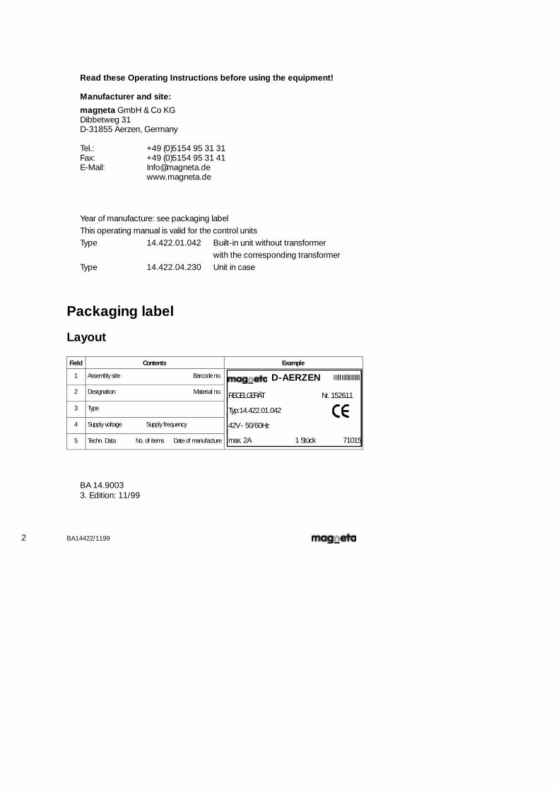
Packaging label
Layout
Field Contents Example
1 Assembly site Barcode no. D-AERZEN2 Designation Material no. REGELGERÄT Nr. 152611
3 Type
REGELGERÄT Nr. 152611
Typ:14.422.01.042
4 Supply voltage Supply frequency
Typ:14.422.01.042
42V - 50/60Hz
5 Techn. Data No. of items Date of manufacture max. 2A 1 Stück 71015
BA 14.90033. Edition: 11/99
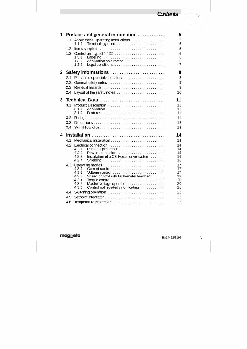
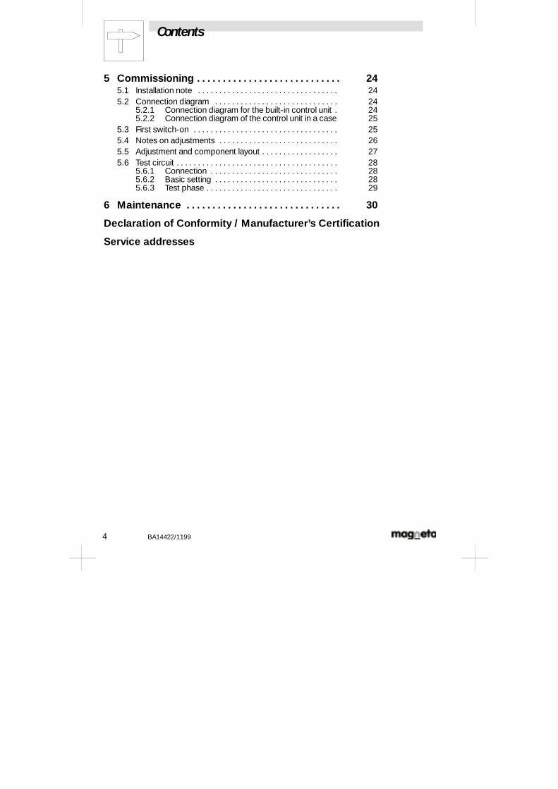
Contents
BA14422/1199 3
1 Preface and general information 5. . . . . . . . . . . .1.1 About these Operating Instructions 5. . . . . . . . . . . . . . . . .
1.1.1 Terminology used 5. . . . . . . . . . . . . . . . . . . . . . . . .1.2 Items supplied 5. . . . . . . . . . . . . . . . . . . . . . . . . . . . . . . . . .1.3 Control unit type 14.422 6. . . . . . . . . . . . . . . . . . . . . . . . . .
1.3.1 Labelling 6. . . . . . . . . . . . . . . . . . . . . . . . . . . . . . . .1.3.2 Application as directed 6. . . . . . . . . . . . . . . . . . . . .1.3.3 Legal conditions 7. . . . . . . . . . . . . . . . . . . . . . . . . .
2 Safety informations 8. . . . . . . . . . . . . . . . . . . . . . . .2.1 Persons responsible for safety 8. . . . . . . . . . . . . . . . . . . . .2.2 General safety notes 9. . . . . . . . . . . . . . . . . . . . . . . . . . . . .2.3 Residual hazards 9. . . . . . . . . . . . . . . . . . . . . . . . . . . . . . . .2.4 Layout of the safety notes 10. . . . . . . . . . . . . . . . . . . . . . . . .
3 Technical Data 11. . . . . . . . . . . . . . . . . . . . . . . . . . . .3.1 Product Description 11. . . . . . . . . . . . . . . . . . . . . . . . . . . . . .
3.1.1 Application 11. . . . . . . . . . . . . . . . . . . . . . . . . . . . . .3.1.2 Features 11. . . . . . . . . . . . . . . . . . . . . . . . . . . . . . . .
3.2 Ratings 11. . . . . . . . . . . . . . . . . . . . . . . . . . . . . . . . . . . . . . . .3.3 Dimensions 12. . . . . . . . . . . . . . . . . . . . . . . . . . . . . . . . . . . . .3.4 Signal flow chart 13. . . . . . . . . . . . . . . . . . . . . . . . . . . . . . . . .
4 Installation 14. . . . . . . . . . . . . . . . . . . . . . . . . . . . . . . .4.1 Mechanical installation 14. . . . . . . . . . . . . . . . . . . . . . . . . . . .4.2 Electrical connection 14. . . . . . . . . . . . . . . . . . . . . . . . . . . . .
4.2.1 Personal protection 14. . . . . . . . . . . . . . . . . . . . . . .4.2.2 Power connection 15. . . . . . . . . . . . . . . . . . . . . . . .4.2.3 Installation of a CE-typical drive system 16. . . . . . .4.2.4 Shielding 16. . . . . . . . . . . . . . . . . . . . . . . . . . . . . . . .
4.3 Operating modes 17. . . . . . . . . . . . . . . . . . . . . . . . . . . . . . . .4.3.1 Current control 17. . . . . . . . . . . . . . . . . . . . . . . . . . .4.3.2 Voltage control 17. . . . . . . . . . . . . . . . . . . . . . . . . . .4.3.3 Speed control with tachometer feedback 18. . . . .4.3.4 Torque control 20. . . . . . . . . . . . . . . . . . . . . . . . . . . .4.3.5 Master-voltage operation 20. . . . . . . . . . . . . . . . . . .4.3.6 Control not isolated / not floating 21. . . . . . . . . . . .
4.4 Switching operation 22. . . . . . . . . . . . . . . . . . . . . . . . . . . . . .4.5 Setpoint integrator 22. . . . . . . . . . . . . . . . . . . . . . . . . . . . . . .4.6 Temperature protection 22. . . . . . . . . . . . . . . . . . . . . . . . . . .
Contents
4 BA14422/1199
5 Commissioning 24. . . . . . . . . . . . . . . . . . . . . . . . . . . .5.1 Installation note 24. . . . . . . . . . . . . . . . . . . . . . . . . . . . . . . . .5.2 Connection diagram 24. . . . . . . . . . . . . . . . . . . . . . . . . . . . .
5.2.1 Connection diagram for the built-in control unit 24.5.2.2 Connection diagram of the control unit in a case 25
5.3 First switch-on 25. . . . . . . . . . . . . . . . . . . . . . . . . . . . . . . . . .5.4 Notes on adjustments 26. . . . . . . . . . . . . . . . . . . . . . . . . . . .5.5 Adjustment and component layout 27. . . . . . . . . . . . . . . . . .5.6 Test circuit 28. . . . . . . . . . . . . . . . . . . . . . . . . . . . . . . . . . . . . .
5.6.1 Connection 28. . . . . . . . . . . . . . . . . . . . . . . . . . . . . .5.6.2 Basic setting 28. . . . . . . . . . . . . . . . . . . . . . . . . . . . .5.6.3 Test phase 29. . . . . . . . . . . . . . . . . . . . . . . . . . . . . . .
6 Maintenance 30. . . . . . . . . . . . . . . . . . . . . . . . . . . . . .
Declaration of Conformity / Manufacturer’s Certification
Service addresses
Preface and general information
BA14422/1199 5
1 Preface and general information
1.1 About these Operating Instructions
- These Operating Instructions are provided to ensure safe working on andwith the Control unit type 14.422. They include safety notes that must befollowed.
- All persons that work on and with the control units must have theseOperating Instructions available while they are working, and must observethe relevant notes and instructions.
- The Operating Instructions must always be complete and in a perfectlylegible condition.
1.1.1 Terminology used
Drive system
For drives with control units in conjunction with other drive components, theterms ”drive system” is used.
1.2 Items supplied
- The items supplied with the Control unit type 14.422.01.042 are:- 1 control unit, type 14.422- 1 setpoint potentiometer- 1 rotary knob for setpoint pot.- 1 scale ( 0 - 100% )- 1 Operating Instructions
- The items supplied with the Control unit type 14.422.04.230 are:- 1 control unit, type 14.422- 1 setpoint potentiometer- 1 knob for setpoint pot.- 1 scale ( 0 - 100% )- 1 transformer, type 14.422.02.230 (230V)- complete and built into case- 1 Operating Instructions
- Immediately on reception, check that the contents of the delivery matchthe accompanying delivery documentation. magneta will not recognize anywarranty for defects that are claimed at a later date. Claim for:- visible transport damage immediately to the supplier,- visible defects/incomplete equipment immediately to magneta.
Preface and general information
6 BA14422/1199
1.3 Control unit type 14.422
1.3.1 Labelling
- magneta control units are uniquely identified by the contents of thenameplate.
- CE-labelling: conforms to the EC-Directive ”Low-Voltage”
1.3.2 Application as directed
- Control units must only be used under the conditions that are described inthese Operating Instructions.
Control units
- are components- for the activation of magnetic particle clutches and brakes,- for building into a machine,- or for combination with other components in a machine.
- are electrical equipment, to be mounted in control cabinets or similarclosed spaces.
- fulfill the safety requirements of the EC-Directive ”Low Voltage”.
- are not themselves machines in the sense of the EC-Directive ”Machines”.
- are not domestic equipment, but intended to be used exclusively asindustrial components.
Drive systems with control units
- conform to the EC-Directive ”Electromagnetic Compatibility”, if they areinstalled according to the instructions for the CE-typical drive system.
- can be operated- from public and private supply networks,- in industrial, commercial and residential areas.
- The user is responsible for ensuring the compliance with EC-Directives inthe particular machine application.
Any other use shall be deemed inappropriate!
Preface and general information
BA14422/1199 7
1.3.3 Legal conditions
Liability
- The information, dates and instructions in the Operating Instructions wereup to date at the time of printing. No rights or warranty for equipment thathas already been supplied may be derived from the information, diagrams,or descriptions.
- The notes on process methods and extracts from circuit diagrams in thisoperating manual are only suggestions. The applicability to a specificapplication must be checked in each case. No liability is accepted bymagneta as to the suitability of any of the procedures or circuitrecommendations included here.
- No liability will be accepted for damage or disturbance caused by:- ignoring this operating manual,- unauthorized alterations to the equipment,- operator errors,- incorrect working on or with the control unit.
Warranty
- Guarantee conditions: see magneta GmbH & Co KG conditions of salesand delivery.
- Report any claims under guarantee to magneta immediately on discoveryof the defect or fault.
- The guarantee is void in all cases where liability cannot be established.
Safety information
8 BA14422/1199
2 Safety information
2.1 Persons responsible for safety
Operator
- The operator is any natural or legal person who uses the drive system or inwhose name the drive system is used.
- The operator or the person entrusted by the operator with theresponsibility for safety must ensure- that all relevant regulations, instructions and laws are observed,- that only qualified personnel work on and with the control unit,- that the operating manual is available to the personnel for all actions
where it is appropriate,- that unqualified persons are prevented from working on or with this
fast-operating unit.
Qualified personnel
Qualified personnel are persons who, as a result of their education, training andexperience, as well as knowledge of the relevant standards and regulations,safety standards and operating condition, have the authority of the personresponsible for the safety of the plant to perform the particular tasks required,being able to recognize and avoid possible dangers.(Definition of qualified personnel according to IEC 364)
Safety information
BA14422/1199 9
2.2 General safety notes
- These safety notes do not make any claim to be complete. In the event ofproblems or queries, please contact magneta.
- The control unit corresponds to the state of the art at the time of delivery,and is fundamentally safe in operation.
- A control unit may create a hazard for personnel, for the equipment itselfand for other property of the operator, if- unqualified persons work on or with the control unit,- the control unit is used in a manner that is not approved.
- The notes on process methods and extracts from circuit diagrams in theseOperating Instructions are only suggestions. The applicability to a specificapplication must be checked in each case.
- The control units must be incorporated in to the plan in such a way thatwhen they are properly installed and used in an approved manner infault-free operation, they fulfill their function and do not create any hazardfor personnel. This applies also to their interaction with the rest of thesystem.
- Take additional measures to make sure that the consequences of faultyoperation are limited and cannot cause hazards for personnel or property:- electrical or non-electrical protective devices (interlocks or mechanical
lock-outs)- system-wide measures.
- Only operate the control unit when it is in perfect order.
- Alterations or changes to the control unit are forbidden,(see Chap. 1.3.3Liability and guarantee).
2.3 Residual hazards
Personal protection
Thecapacitorsand variousother componentscanstillhavedangerousvoltageson them for up to 3 minutes after switching off the supply power.
Safety information
10 BA14422/1199
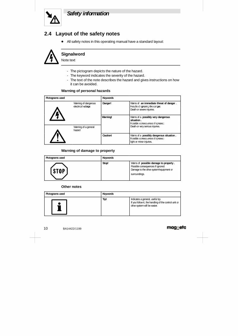
2.4 Layout of the safety notes- All safety notes in this operating manual have a standard layout:
SignalwordNote text
- The pictogram depicts the nature of the hazard.- The keyword indicates the severity of the hazard.- The text of the note describes the hazard and gives instructions on how
it can be avoided.
Warning of personal hazards
Pictograms used Keywords
Warning of dangerouselectrical voltage
Danger! Warns of an immediate threat of danger .Results of ignoring the danger:electrical voltage Results of ignoring the danger:Death or severe injuries.
Warning! Warns of a possibly very dangeroussituation .Possible consequences if ignored:
Warning of a generalhazard
Possible consequences if ignored:Death or very serious injuries.
Caution! Warns of a possibly dangerous situation .Possible consequences if ignored:Possible consequences if ignored:light or minor injuries.
Warning of damage to property
Pictograms used Keywords
Stop! Warns of possible damage to property .Possible consequences if ignored:Damage to the drive system/equipment or
surroundings.
Other notes
Pictograms used Keywords
Tip! Indicates a general, useful tip.If you follow it, the handling of the control unit ordrive system will be easier.
Technical Data
BA14422/1199 11
3 Technical Data
3.1 Product Description
3.1.1 ApplicationThe built-in power supply ensures that a constant current flows, despitevariable coil temperature. This keeps the torque constant.In certain applications, a control of the voltage can be achieved through asimple switch on the controller board (Chap. 4.3.2).
3.1.2 FeaturesThe14.422controlunit isused toactivate magnetic particleclutchesandbrakes.Theexcitationcurrent canbecontrolled byadancer or floating potentiometer, orbyacontrolvoltage.Thedesired torqueorexcitationcurrent issetbythesetpointpotentiometer.Sincethedeviceoperateswitha24Vnominalouputvoltage,but theinputvoltagedepends on themains supply voltage, thecontrol unit must beconnected to theAC supply through a transformer.
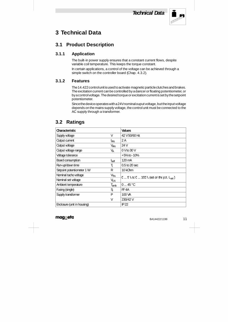
3.2 Ratings
Characteristic ValuesSupply voltage V 42 V 50/60 HzOutput current IAN 2 AOutput voltage VAN 24 VOutput voltage range VA 0 V to 30 VVoltage tolerance +5% to -10%Board consumption Iself 120 mARun-up/down time Ti 0.5 to 20 secSetpoint potentiometer 1 W R 10 kOhmNominal tacho voltage VTN 0 ... 5 V to 0 ... 100 V (set on the pot. Uset )Nominal set voltage VLN
0 ... 5 V to 0 ... 100 V (set on the pot. Uset )
Ambient temperature Tamb 0 ... 45 °CFusing (single) Si FF 4ASupply transformer P 100 VA
V 230/42 VEnclosure (unit in housing) IP 22
Technical Data
12 BA14422/1199
Stop!When the unit is built into a case, ensure that there is adequate air flow. Themaximum ambient temperature of 45 °C must be observed!
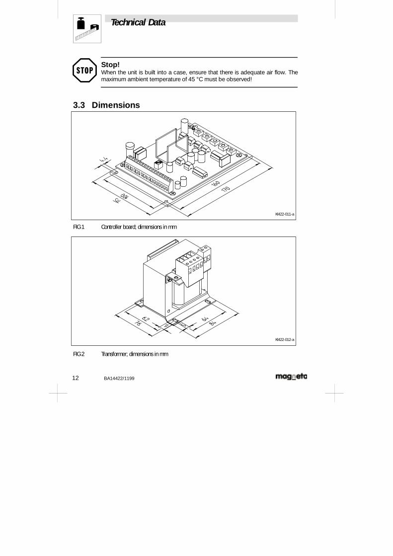
3.3 Dimensions
Kl422-011-a
FIG 1 Controller board; dimensions in mm
Kl422-012-a
FIG 2 Transformer; dimensions in mm
Technical Data
BA14422/1199 13
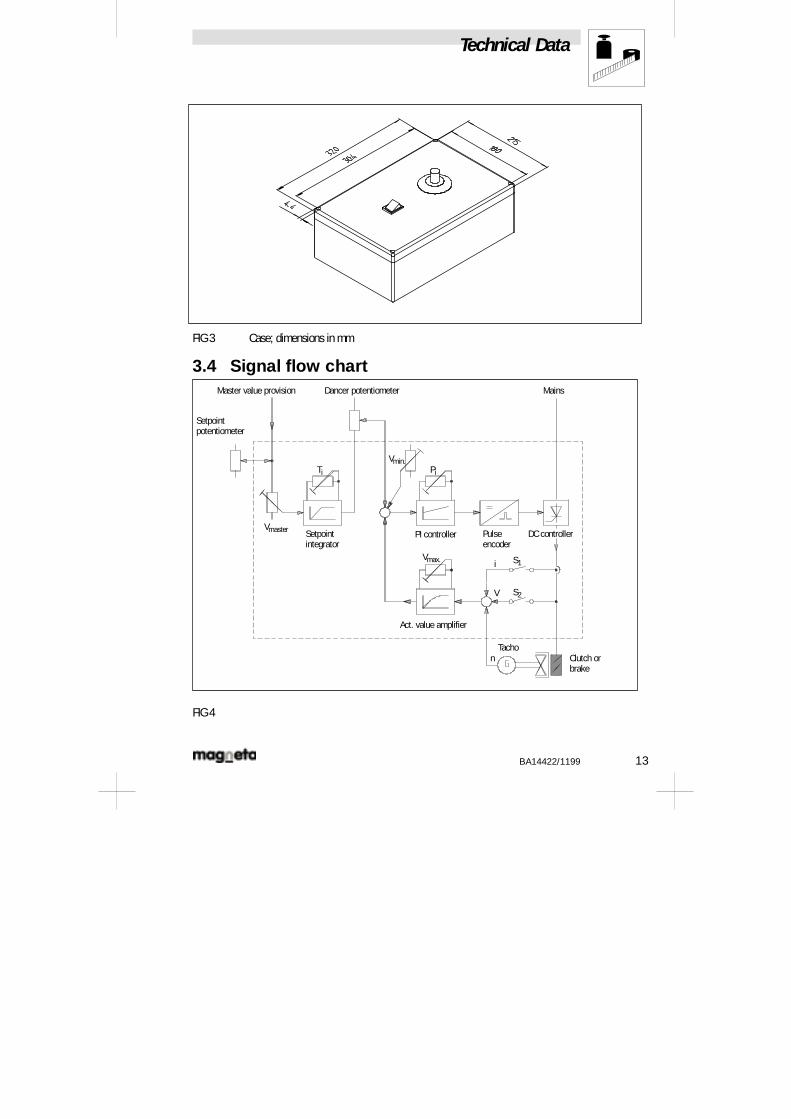
FIG 3 Case; dimensions in mm
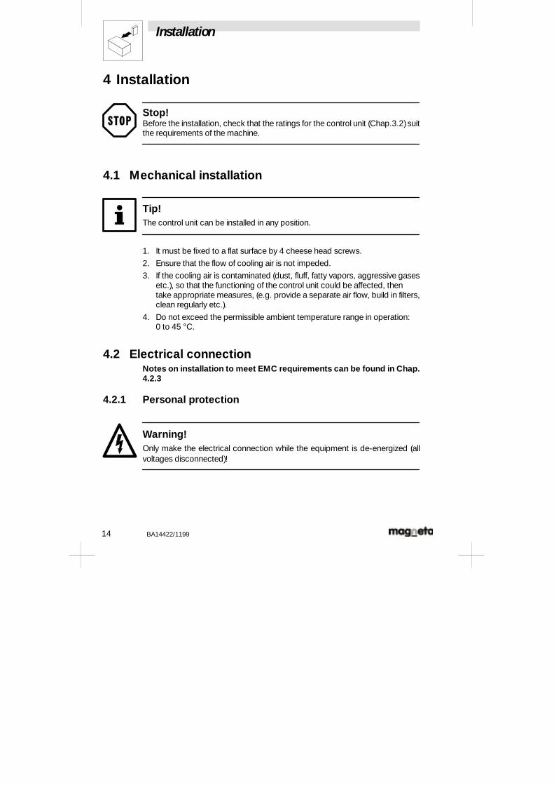
3.4 Signal flow chartMainsDancer potentiometer
Setpointpotentiometer
Master value provision
Setpointintegrator
Vmaster
Vmin.
PI controller Pulseencoder
DC controller
Vmax.
Act. value amplifier
TachoClutch orbrake
V
i
n
Ti Pi
S1
S2
FIG 4
Installation
14 BA14422/1199
4 Installation
Stop!Before the installation, check that the ratings for the control unit (Chap.3.2)suitthe requirements of the machine.
4.1 Mechanical installation
Tip!The control unit can be installed in any position.
1. It must be fixed to a flat surface by 4 cheese head screws.
2. Ensure that the flow of cooling air is not impeded.
3. If the cooling air is contaminated (dust, fluff, fatty vapors, aggressive gasesetc.), so that the functioning of the control unit could be affected, thentake appropriate measures, (e.g. provide a separate air flow, build in filters,clean regularly etc.).
4. Do not exceed the permissible ambient temperature range in operation:0 to 45 °C.
4.2 Electrical connectionNotes on installation to meet EMC requirements can be found in Chap.4.2.3
4.2.1 Personal protection
Warning!Only make the electrical connection while the equipment is de-energized (allvoltages disconnected)!
Installation
BA14422/1199 15
- Personal protection to DIN VDE 0100 with r.c.c.b. devices:
The control units include an internal mains rectifier. An earth fault can result in aDC that prevents a traditional fault-current device from tripping. We thereforerecommend the use of ”universal-current sensitive” r.c.c.b. devices.
- When dimensioning the trip current, please take note that capacitivecompensation currents in the shielding leads and interferencesuppression filters during operation may cause spurious tripping.
- Remarks on the use of universal-current sensitive r.c.c.b. devices:- The German Committee K 226 has decided on the recommendation in
the standard pr EN 50 178 (previously VDE 0160) for the use ofuniversal-current sensitive r.c.c.b. devices.
- The final decision on the use as a standard will be made by theCENELEC/CS (European Committee for ElectrotechnicalStandardization) in Brussels. Further information on the use ofuniversal-current sensitive r.c.c.b. devices can be obtained from themanufacturers of these devices.
Warning!Faulty fuses should only be replaced while the equipment is de-energized,and onlyby thespecified type!Thecontrolunit maycarrydangerous voltages forup to 3 minutes after the power has been disconnected.
4.2.2 Power connection
- When dimensioning the cross-section of the supply leads, take account ofthe current consumption of the control unit and the voltage drop underload.
- The possible conformity with other standards (e.g. VDE 0113, VDE 02898or similar) is the responsibility of the user.
- Observe the max. permissible tightening torques for the screws in theterminal strips:
M = 0.7 to 0.8 Nm
Installation
16 BA14422/1199
4.2.3 Installation of a CE-typical drive system
General notes
- The electromagnetic compatibility of a machine depends on the methodand the care taken in the installation. The following must be observed:- Layout- Filtering- Shielding- Earthing
- If the installation is different, then it will be necessary to test that themachine or system keeps within the EMC limits for conformity with theEMC-Directive. This will be necessary, for instance:- if unshielded cables are used.
Stop!Conformity with the EMC-Directive in the machine application is part ofthe responsibility of the application.
- If the following measures are observed, you can be sure that the drivesystem will not cause any EMC problems while the machine isoperating, and the EMC-Directive will be fulfilled.
Tip!If equipment that does not meet the CE-requirements for interference immunityto EN 50082-2 is operated in the vicinity of the control unit, then this equipmentmay affect the functioning of the control unit.
4.2.4 Shielding
Shield the control cables:- Connect up the shielding for analog control cables at one end,
- Connect the shielding of the control cables by the shortest route to theshield terminals provided on the control unit.
Installation
BA14422/1199 17
If control units are used in residential areas:
- An additional damping of 10 dB must be provided by the shielding, to limitradiated interference. This can usually be achieved by installation innormal closed and earthed metallic control cabinets or housings.
4.3 Operating modes
4.3.1 Current control
Current control can be used to regulate the excitation current of a magneticparticle clutch or brake.
The desired torque or excitation current is set with the setpoint potentiometer.The excitation current can also be determined by a dancer potentiometer or amaster voltage. The minimum or maximum output current can be set by thetrimmers Vmin or Vmax .
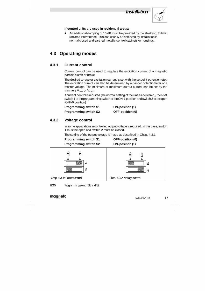
If current control is required (the normal setting of the unit as delivered), then setswitch1of theprogrammingswitchto theON-1positionand switch2 to beopen(OFF-0 position).
Programming switch S1 ON-position (1)
Programming switch S2 OFF-position (0)
4.3.2 Voltage control
In some applications a controlled output voltage is required. In this case, switch1 must be open and switch 2 must be closed.
The setting of the output voltage is made as described in Chap. 4.3.1
Programming switch S1 OFF-position (0)
Programming switch S2 ON-position (1)
Chap. 4.3.1: Current control Chap. 4.3.2: Voltage control
S1S2
ONOFF
S1S2
ON
OFF
FIG 5 Programming switch S1 and S2
Installation
18 BA14422/1199
4.3.3 Speed control with tachometer feedback
MPC
Load
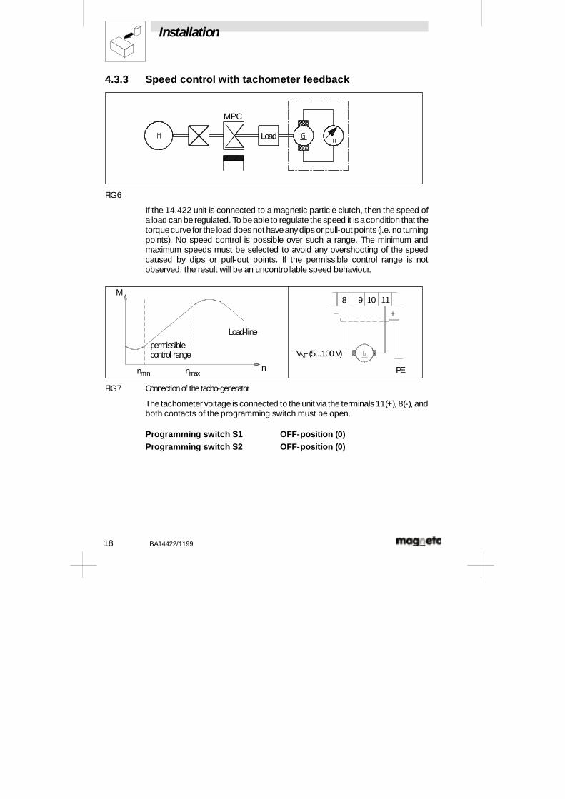
FIG 6
If the 14.422 unit is connected to a magnetic particle clutch, then the speed ofa load can be regulated. To beable to regulate thespeed it is acondition that thetorquecurve for the load does not haveanydips or pull-out points (i.e. no turningpoints). No speed control is possible over such a range. The minimum andmaximum speeds must be selected to avoid any overshooting of the speedcaused by dips or pull-out points. If the permissible control range is notobserved, the result will be an uncontrollable speed behaviour.
Load-line
permissiblecontrol range
nmin nmaxn
M8 9 10 11
PE
VNT (5...100 V)
FIG 7 Connection of the tacho-generator
The tachometer voltage is connected to theunit via the terminals 11(+), 8(-), andboth contacts of the programming switch must be open.
Programming switch S1 OFF-position (0)Programming switch S2 OFF-position (0)
Installation
BA14422/1199 19
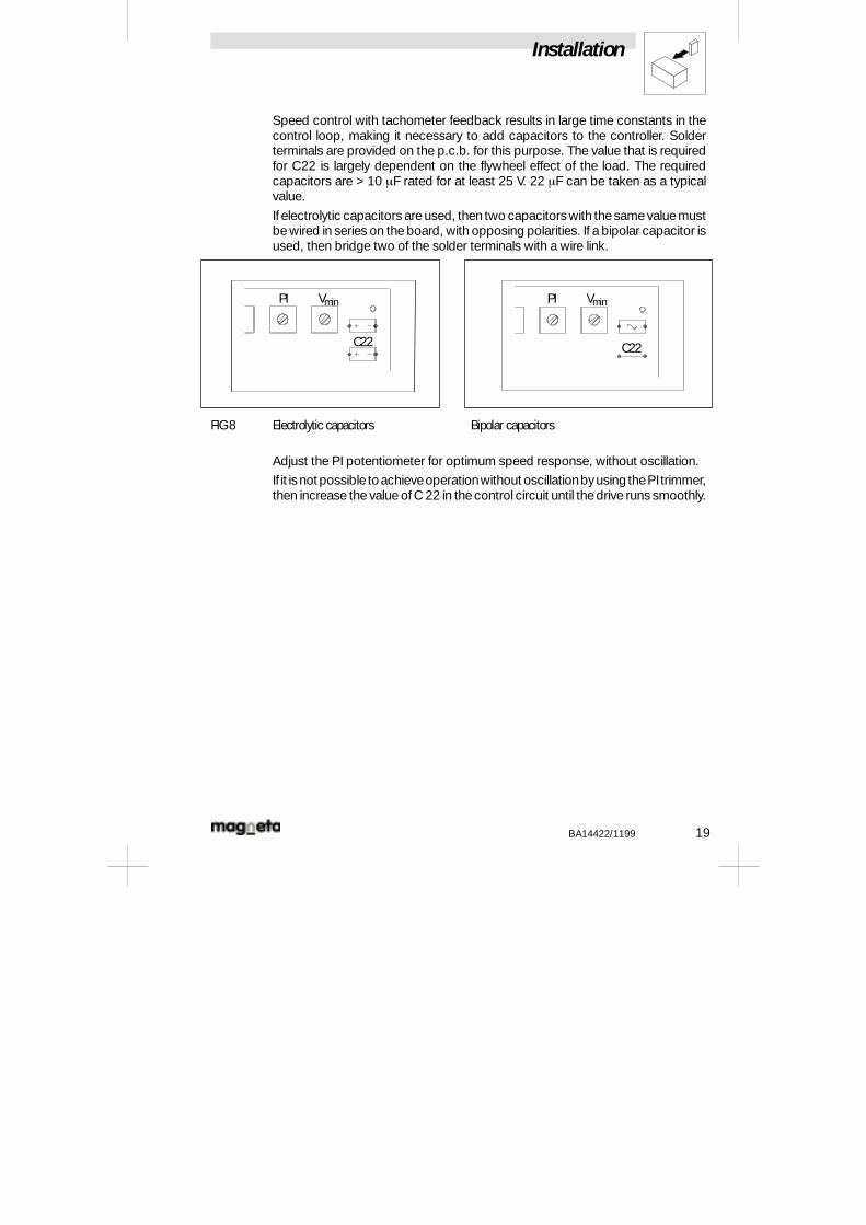
Speed control with tachometer feedback results in large time constants in thecontrol loop, making it necessary to add capacitors to the controller. Solderterminals are provided on the p.c.b. for this purpose. The value that is requiredfor C22 is largely dependent on the flywheel effect of the load. The requiredcapacitors are > 10 mF rated for at least 25 V. 22 mF can be taken as a typicalvalue.
If electrolytic capacitors areused, then two capacitors with thesamevaluemustbe wired in series on the board, with opposing polarities. If a bipolar capacitor isused, then bridge two of the solder terminals with a wire link.
PI Vmin
C22
PI Vmin
C22
FIG 8 Electrolytic capacitors Bipolar capacitors
Adjust the PI potentiometer for optimum speed response, without oscillation.
If it isnot possible toachieveoperationwithout oscillationbyusing thePItrimmer,then increase the value of C 22 in thecontrol circuit until thedrive runs smoothly.
Installation
20 BA14422/1199
4.3.4 Torque control
For torque control, the same wiring diagram and component values are used asfor speed control (Chap. 4.3.3). A torque sensor is attached instead of atachometer.
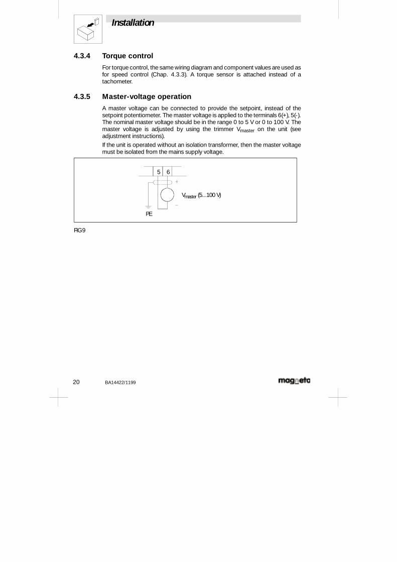
4.3.5 Master-voltage operation
A master voltage can be connected to provide the setpoint, instead of thesetpoint potentiometer. The master voltage is applied to the terminals 6(+), 5(-).The nominal master voltage should be in the range 0 to 5 V or 0 to 100 V. Themaster voltage is adjusted by using the trimmer Vmaster on the unit (seeadjustment instructions).
If the unit is operated without an isolation transformer, then the master voltagemust be isolated from the mains supply voltage.
5 6
PE
Vmaster (5...100 V)
FIG 9
Installation
BA14422/1199 21
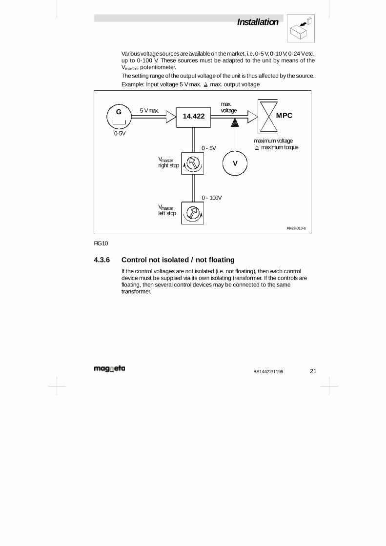
Variousvoltagesourcesareavailableon themarket, i.e.0-5 V;0-10 V;0-24 Vetc.up to 0-100 V. These sources must be adapted to the unit by means of theVmaster potentiometer.
The setting range of the output voltage of the unit is thus affected by the source.
Example: Input voltage 5 V max. max. output voltage
Kl422-013-a
MPCG14.422
0-5V
5 V max.max.voltage
maximum voltagemaximum torque
Vmasterright stop
Vmasterleft stop
0 - 5V
0 - 100V
V
FIG 10
4.3.6 Control not isolated / not floating
If the control voltages are not isolated (i.e. not floating), then each controldevice must be supplied via its own isolating transformer. If the controls arefloating, then several control devices may be connected to the sametransformer.
Installation
22 BA14422/1199
4.4 Switching operation
Warning!The load circuit must only be switched while the current is zero!
When the ”controller inhibit” switch is closed, no trigger pulses will be produced(output voltage = 0 V).
4.5 Setpoint integrator
In the event of a setpoint step, the output voltage will respond at a rate that canbeset by the trimmer Ti . Therun-up/down times canbeset from 0.5 to 20 secs.
4.6 Temperature protection
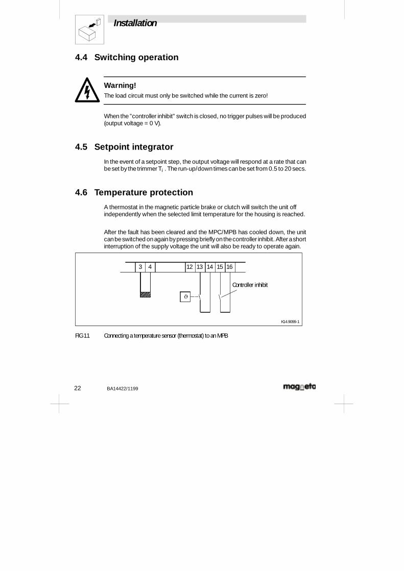
A thermostat in the magnetic particle brake or clutch will switch the unit offindependently when the selected limit temperature for the housing is reached.
After the fault has been cleared and the MPC/MPB has cooled down, the unitcanbeswitched onagainbypressing brieflyon thecontroller inhibit. Afterashortinterruption of the supply voltage the unit will also be ready to operate again.
3 4 12 13 14
J
15 16
K14.9099-1
Controller inhibit
FIG 11 Connecting a temperature sensor (thermostat) to an MPB
Installation
BA14422/1199 23
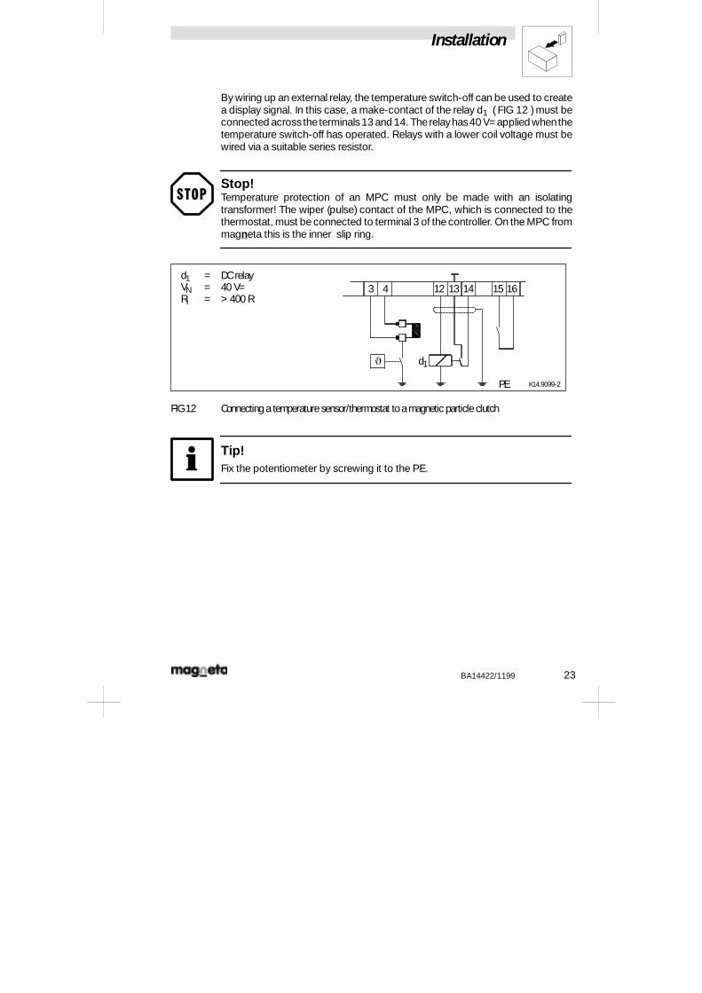
By wiring up an external relay, the temperature switch-off can be used to createa display signal. In this case, a make-contact of the relay d1 (FIG 12 ) must beconnected across theterminals13 and 14. Therelayhas40 V= applied whenthetemperature switch-off has operated. Relays with a lower coil voltage must bewired via a suitable series resistor.
Stop!Temperature protection of an MPC must only be made with an isolatingtransformer! The wiper (pulse) contact of the MPC, which is connected to thethermostat, must be connected to terminal 3 of the controller. On the MPC frommagneta this is the inner slip ring.
d1 = DC relayVN = 40 V=RI = > 400 R
J
PE
3 4 12 13 14
d1
15 16
K14.9099-2
FIG 12 Connecting a temperature sensor/thermostat to a magnetic particle clutch
Tip!Fix the potentiometer by screwing it to the PE.
Commissioning
24 BA14422/1199
5 Commissioning
5.1 Installation note
Stop!If the unit is built into a case, care must be taken to ensure adequate ventilation.The ambient temperature must not exceed 45 EC. Control cables must beshielded, and connected to PE at one end.
5.2 Connection diagram
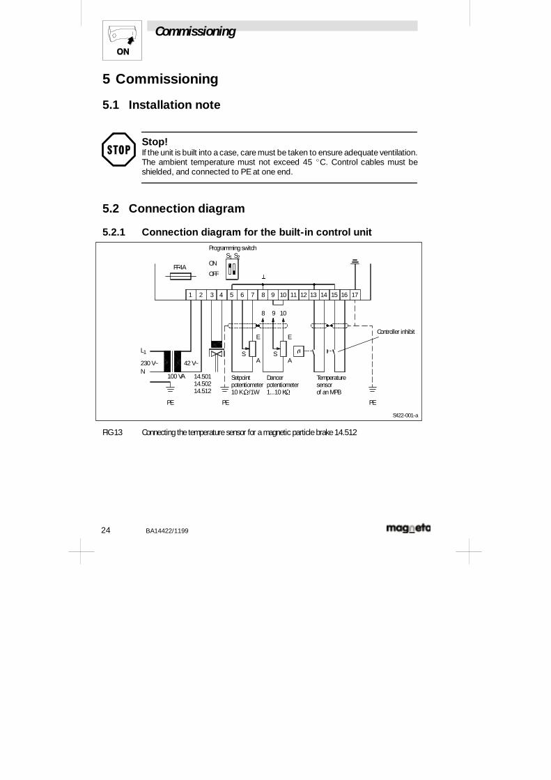
5.2.1 Connection diagram for the built-in control unit
1 2 3 4 5 6 7 8 9 10 11 12 13 14 15 16 17
FF4A
Programming switchS1 S2
E
SA
S
E
A
PEPEPE
N
L1
230 V~ 42 V~
8 9 10
Controller inhibit
Dancerpotentiometer1...10 KW
Setpointpotentiometer10 KW/1W
100 VA 14.50114.50214.512
Temperaturesensorof an MPB
^
J
ON
OFF
S422-001-a
FIG 13 Connecting the temperature sensor for a magnetic particle brake 14.512
Commissioning
BA14422/1199 25
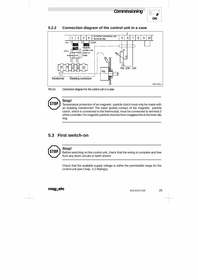
5.2.2 Connection diagram of the control unit in a case
1 2 3 4 5 6 7 8 9 10
S
E
A
S422-003-a
Pot. 10K - 1W
Shielding connectionTransformer
PE PE PERL1
Mp
N
1.5
1.5
1.5
1.5
1.5
1.5
1.542V�
220V�5 2
14
110VA
for further connections, seeTechnical Data
Magneticpowder-coreclutch orbrake
Pot.
FIG 14 Connection diagram for the control unit in a case
Stop!Temperature protection of an magnetic particle clutch must only be made withan isolating transformer! The wiper (pulse) contact of the magnetic particleclutch, which is connected to the thermostat, must be connected to terminal 3of thecontroller. Formagnetic particleclutches from magnetathis is the innerslipring.
5.3 First switch-on
Stop!Before switching on the control unit, check that the wiring is complete and freefrom any short-circuits or earth shorts!
Check that the available supply voltage is within the permissible range for thecontrol unit (see Chap. 3.2 Ratings).
Commissioning
26 BA14422/1199
5.4 Notes on adjustmentsSee Chap. 5.5 (adjustments and component layout)1. Trimmer Vmaster and Ti at left stop2. Trimmer Vmax, Vmin and PI in middle position3. The following must be set with:
Operating mode Programming switch
S1 - position S2 - position
Current control ON - (1) OFF - (0)
Voltage control OFF - (0) ON - (1)
Speed control / torque control OFF - (0) OFF - (0)
4. Attach the tachometer voltage to terminals 11 (+) and 8 (-).5. Solder in capacitor C22, with value 22 mF/25 V (as required for
speed/torque control).6. If a dancer potentiometer is used, the link between 9 and 10 must be
removed. The link must be inserted for all other operating modes.7. Switch on supply power.
8. For setpoint provision from a setpoint potentiometer, trimmer Vmaster mustbe set to the right stop.
9. With master-voltage control, trimmer Vmaster must be rotated to the right(with the master voltage at a maximum), until a voltage of 9 V appearsbetween the terminals 10 (+) and 8 (-).
10. Adjust the setpoint potentiometer to the middle position (or the mastervoltage to the mid-range value).
11. Turn trimmer Vmin. until the desired mimimum value for the output isreached.
12. Turn trimmer Vmax until the desired maximum value for the output isreached.
13. Set the setpoint potentiometer to the left stop (or the master voltage tozero).
14. Turn trimmer Vmin until the desired minimum value for the output isreached.
15. Set the setpoint (and dancer potentiometer, if present) to the right stop.16. Turn trimmer Vmax until the desired maximum value for the output is
reached.17. Repeat the adjustments, as described for the steps 13-16, as often as
required, since the trimmers Vmin and Vmax affect each other.18. The ramp-up/down time for the output is set by trimmer Ti . Turning the
trimmer to the right increases the ramp-up/down time.
Commissioning
BA14422/1199 27
19. The control-loop dynamic response for speed control with tachometerfeedback is set by the PI trimmer. The PI trimmer must be adjusted tooptimize the speed response while avoiding oscillation in operation.
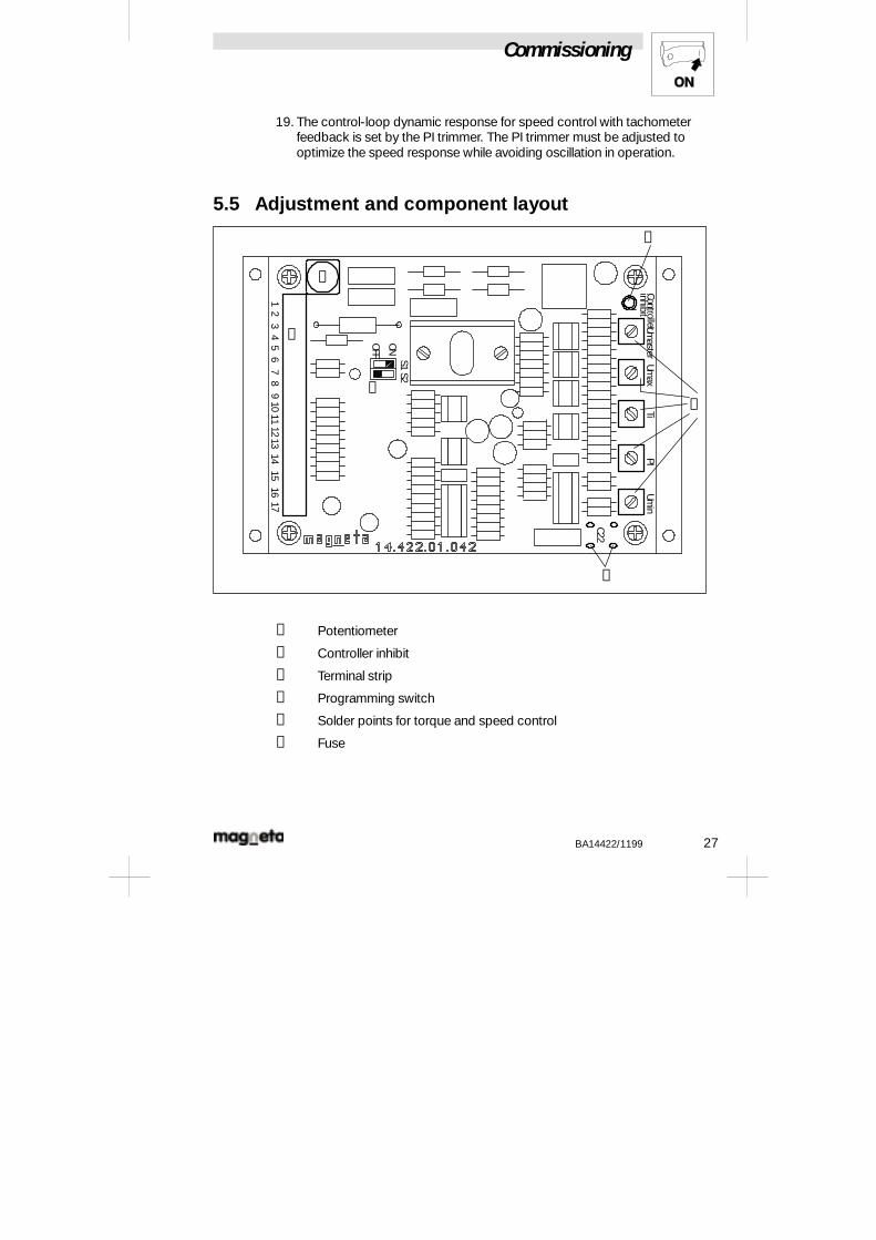
5.5 Adjustment and component layoutUm
asterUm
axTi
PIUm
inControllerinhibit
S1S2
ONOFF
C22
12
34
56
78
910
1112
1314
1516
17
➀
➁
➂
➃
➄
➅
① Potentiometer
② Controller inhibit
③ Terminal strip
④ Programming switch
⑤ Solder points for torque and speed control
⑥ Fuse
Commissioning
28 BA14422/1199
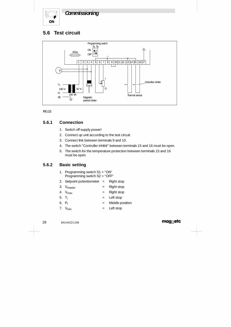
5.6 Test circuit
1 2 3 4 5 6 7 8 9 10 11 12 13 14 15 16 17
FF4A
Programming switchS1 S2
SI
O
PE
N
L1
230 V~ 42 V~
100 VAMagneticparticle brake
^
ON
OFF
v
Controller inhibit
Thermal sensor
FIG 15
5.6.1 Connection
1. Switch off supply power!
2. Connect up unit according to the test circuit.
3. Connect link between terminals 9 and 10.
4. The switch ”Controller inhibit” between terminals 15 and 16 must be open.
5. The switch for the temperature protection between terminals 15 and 16must be open.
5.6.2 Basic setting
1. Programming switch S1 = “ON”Programming switch S2 = “OFF”
2. Setpoint potentiometer = Right stop
3. Vmaster = Right stop
4. Vmax. = Right stop
5. Ti = Left stop
6. PI = Middle position
7. Vmin. = Left stop
Commissioning
BA14422/1199 29
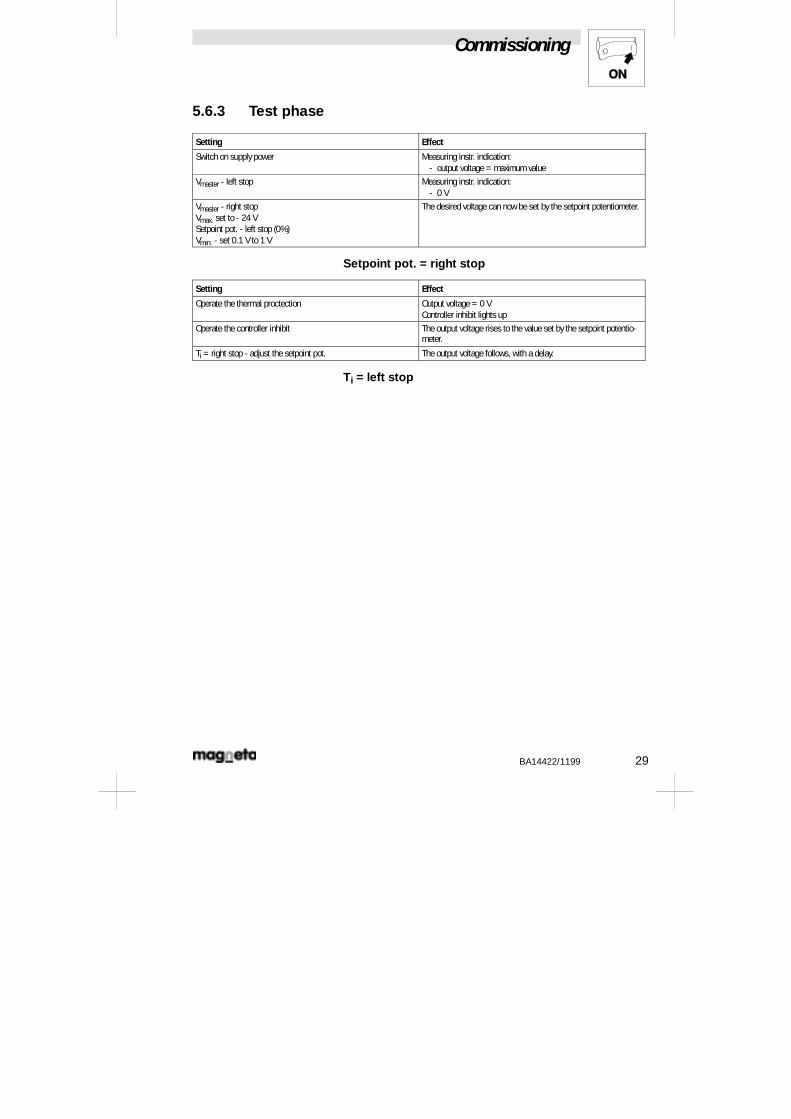
5.6.3 Test phase
Setting Effect
Switch on supply power Measuring instr. indication:- output voltage = maximum value
Vmaster - left stop Measuring instr. indication:- 0 V
Vmaster - right stopVmax. set to - 24 VSetpoint pot. - left stop (0%)Vmin. - set 0.1 V to 1 V
The desired voltage can now be set by the setpoint potentiometer.
Setpoint pot. = right stop
Setting Effect
Operate the thermal proctection Output voltage = 0 VController inhibit lights up
Operate the controller inhibit The output voltage rises to the value set by the setpoint potentio-meter.
Ti = right stop - adjust the setpoint pot. The output voltage follows, with a delay.
Ti = left stop
Maintenance
30 BA14422/1199
6 Maintenance- The control units do not require any maintenance, provided that the
prescribed conditions of operation are observed.
Declaration of Conformity /Manufactuer’s Certification
BA14422/1199 31
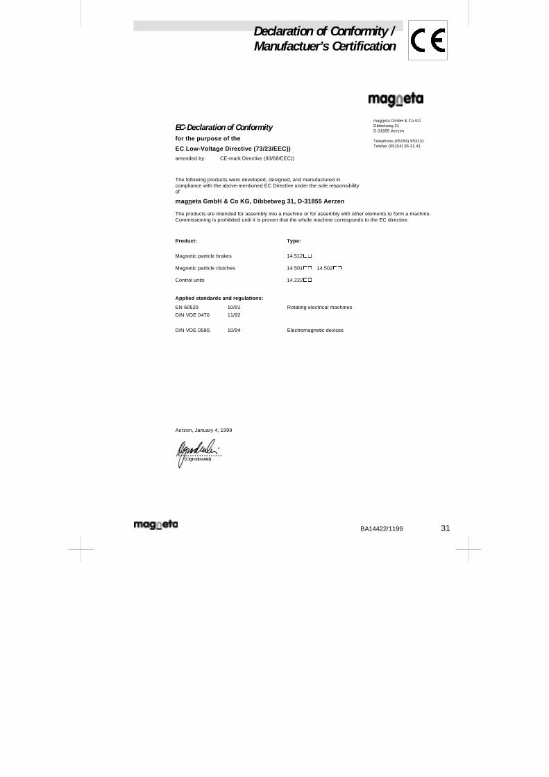
EC-Declaration of Conformityfor the purpose of the
EC Low-Voltage Directive (73/23/EEC))
amended by: CE-mark Directive (93/68/EEC))
The following products were developed, designed, and manufactured incompliance with the above-mentioned EC Directive under the sole responsibilityof
magneta GmbH & Co KG, Dibbetweg 31, D-31855 Aerzen
magneta GmbH & Co KGDibbetweg 31D-31855 Aerzen
Telephone (05154) 953131Telefax (05154) 95 31 41
The products are intended for assembly into a machine or for assembly with other elements to form a machine.Commissioning is prohibited until it is proven that the whole machine corresponds to the EC directive.
Product: Type:
Magnetic particle brakes 14.512oo
Magnetic particle clutches 14.501oo 14.502oo
Control units 14.222oo
Applied standards and regulations:
EN 60529 10/91
DIN VDE 0470 11/92
Rotating electrical machines
DIN VDE 0580, 10/94 Electromagnetic devices
Aerzen, January 4, 1999
(Ogrodowski)....................
Declaration of Conformity /Manufactuer’s Certification
32 BA14422/1199
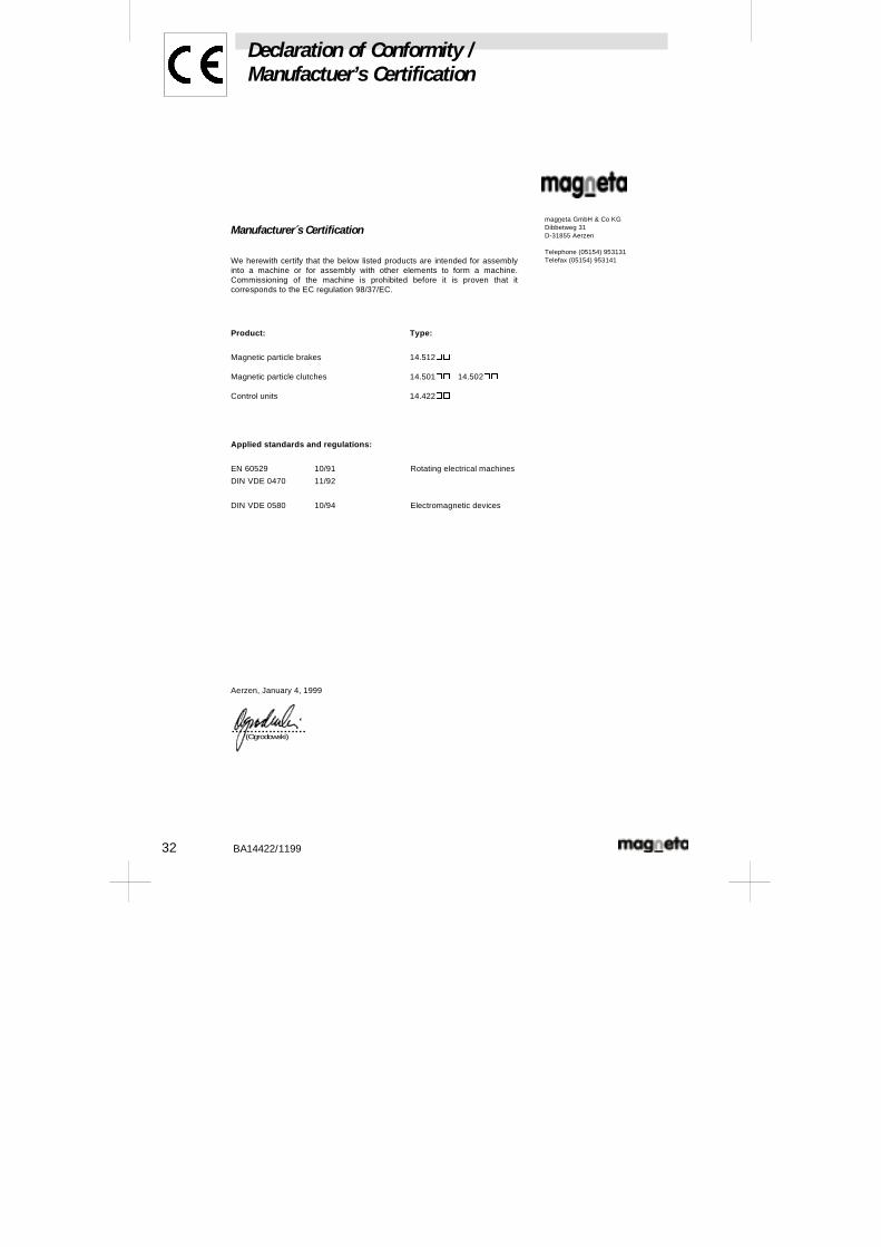
Manufacturer s Certification
We herewith certify that the below listed products are intended for assemblyinto a machine or for assembly with other elements to form a machine.Commissioning of the machine is prohibited before it is proven that itcorresponds to the EC regulation 98/37/EC.
magneta GmbH & Co KGDibbetweg 31D-31855 Aerzen
Telephone (05154) 953131Telefax (05154) 953141
Product: Type:
Magnetic particle brakes 14.512oo
Magnetic particle clutches 14.501oo 14.502oo
Control units 14.422oo
Applied standards and regulations:
EN 60529 10/91
DIN VDE 0470 11/92
Rotating electrical machines
DIN VDE 0580 10/94 Electromagnetic devices
Aerzen, January 4, 1999
(Ogrodowski)....................