Embed Size (px)
Citation preview
HAL Id: jpa-00249125https://hal.archives-ouvertes.fr/jpa-00249125
Submitted on 1 Jan 1994
HAL is a multi-disciplinary open accessarchive for the deposit and dissemination of sci-entific research documents, whether they are pub-lished or not. The documents may come fromteaching and research institutions in France orabroad, or from public or private research centers.
L’archive ouverte pluridisciplinaire HAL, estdestinée au dépôt et à la diffusion de documentsscientifiques de niveau recherche, publiés ou non,émanant des établissements d’enseignement et derecherche français ou étrangers, des laboratoirespublics ou privés.
Magnetic levitation and MHD propulsionPascal Tixador
To cite this version:Pascal Tixador. Magnetic levitation and MHD propulsion. Journal de Physique III, EDP Sciences,1994, 4 (4), pp.581-593. �10.1051/jp3:1994146�. �jpa-00249125�
J. Ph_vs. III Franc-e 4 (1994) 581-593 APRIL 1994, PAGE 581
Classification
Physic-s Abstiacts
85.25J 84.60L
Magnetic levitation and MHD propulsion
P. Tixador
CNRS/CRTBT-LEG, B-P- 166. 38042 Grenoble Cedex 9, France
(Receii,ed 15 July 1993, revised J5 Noi'embei 1993, accepted ?2 Noiember 1993)
Rdsumd. Depuis quelques anndes nous assistons h un reddmarrage de programmes concernant la
ldvitation et la propulsion supraconductrices. Diffdrents systkmes supraconducteuo de ldvitation et
de propulsion seront ddcrits en examinant plus particulibrement l'aspect dlectromagndtique.Quelques programme~ h travers le monde seront abordds. Les train~ h sustentation magndtiquepourraient constituer un nouveau mode de transport terrestre h vites~e dlevde (500 km/h) pour le
21e sidde. Les japonais n'ont cessd de s intdresser h ce systdme avec bobine supraconductrice. Its
envisagent un stade prdindustriel avec la construction d'une ligne de 43km. En 1991 un
programme amdricain pour une durde de six an~ a dtd lancd pour dvaluer )es performances des
systdmes h ldvitation pour le transport aux Etats Unis. La MHD jmagndto-Hydro-Dynamique)prdsente des avantages intdressants pour la propulsion navale et un regain d'intdrdt apparait h
l'heure actuelle. Le japon se situe 16 encore h la pointe des d6veloppements actuels avec en
particulier )es premiers essais en rade de Kobe de Yamato I, navire de 260 tonnes, entraind par
MHD.
Abstract. Magnetic levitation and MHD propulsion are now attracting attention in several
countries. Different superconducting MagLev and MHD systems will be described concentrating
on, above all, the electromagnetic aspect. Some programmes occurring throughout the world will
be described. Magnetic levitated trains could be the new high speed transportation system for the
21st century. Intensive studie~ involving MagLev trains using superconductivity have been carried
out in Japan since 1970. The construction of a 43 km long track is to be the next step. In 1991 a six
year programme was launched in the United States to evaluate the performances of MagLev
systems for tran,portation. The MHD (MagnetoHydroDynamic) offers some interesting advan-
tages (efficiency, stealth characteristics, ...) for naval propulsion and increasing attention is beingpaid towards it nowadays. Japan is also up at the top with the tests of Yamato I, a 260 ton MHD
propulsed ship.
1. Magnetic levitated trains.
I.I INTRODUCTION. The interest in magnetic levitated trains is difficult to appreciate in
France due to the successful French tradition for trains. MagLev vehicles are often compared to
low flying aircraft for intermediate distances rather than trains. Two problems become

582 JOURNAL DE PHYSIQUE III N° 4
important at high speeds for classical railway trains energy transmission (trolley arm and
wire) and the contact between rail and wheel (supporting, mechanical stresses, guidance and
wear). These problems limit the commercial upper speed to 400 km/h even if the TGV has run
at 515.3 km/h, May 18. 1990. MagLev vehicles suppressing these two problems are offering a
new way forward for transportation, but they have to prove their capacity to transport people at
speeds higher or equal to 500 km/h. The problem for the propulsion power remains in all cases
at high speeds since the aerodynamic drag power increases as the cube of the speed. The use of
low pressure tubes would decrease this propulsion power, but this future aspect is out the area
concerned by this article.
The interest in MagLev, in addition to its possibility for travel at high speds, is its lower
noise level, absence of track wear, and ride quality. Nevertheless, the aerodynamic noises
become dominating at high speeds compared to rolling noises (typically above 300 km/h [1]).
1.2 OPERATING PRINCIPLE. The idea to use an a-c- excited coil for the levitation and
propulsion was first discovered by a French inventor, Bachelet, in 1914, but the first important
studies only began in the sixties, particularly in the United States (at MIT) which stopped them
in the seventies. Only the Germans and Japanese kept on important programmes up to now,
while the United States started their programmes up again in 1990. The magnetic levitation
may be electromagnetic or electrodynamic.The electromagnetic system is based on the attraction between controlled electromagnets
and a magnetic track. The gap is small (10 to 15 mm) with conventional magnets and has to be
actively controlled with very high reliability. German researchers are working on this system
(development of Transrapid vehicles) but as no superconductivity is involved, no further
details will be given.The electrodynamic system is based on the repulsion between electromagnets on board anti
conducting sheets or short circuited coils on the track. The power dissipated in the track is
called magnetic drag and brakes the vehicle. Sheets are less complex but coils redube the
magnetic drag. No control is required, but this natural levitation is only possible above a
certain speed, roughly 70km/h. The clearance may be large (100, 150 mm) if powerfulsuperconducting magnets are used.
Once in levitation, the vehicle has to be guided and propelled. These functions may be
accomplished separately or in combination.
For the electrodynamic system, guidance is performed by the interaction between a magnet
on board (identical or different to the magnet for levitation) and coils or conductive sheets on
the track. The guidance may be assumed for example by zero flux coils as shown in figure I.
No eddy current is induced (no magnetic drag) when the vehicle is at the centre, but as soon as
it is no more in this position, currents are induced and they create righting electromagneticforces. The same coils may be used for propulsion [2]. The vehicle is propelled in both cases
Field createdby on board
magnets
,,,'~ Supply
' (combined propulsion)
Fig. I. Zero flux coil for guidance.

N° 4 MAGNETIC LEVITATION AND MHD PROPULSION 583
(electromagnetic and electrodynamic systems) by a linear electrical motor. Asynchronous
solutions are not suited for electrodynamic systems without magnetic materials and with a
large« gap »
(low efficiency and power factor). The best solution for the electrodynamic
system is the synchronous linear motor with the field winding on board. The multiphase
armature windings on the track are supplied by a power converter whose frequency
~f j is matched to the speed (V of the vehicle (V=
2 fL~, L~ magnet pole pitch). With this
active track the power on board is minimal and the problem of energy supply is thus solvid.
The power on board for propulsion is indeed theoretically zero (short circuited superconductingmagnets). It is reduced practically to just the thermal losses of the cryostat. The power on board
for the helium refrigerator, lighting and air-conditioning may be electromagnetically suppliedwithout contact through the track coils for the levitation and special coils on board usingharmonic fields [3]. At low speeds batteries supply the power.
In all cases superconducting coils operate in persistent mode, see for instance the second
part of the paper.
1.3 JAPANESE PROGRAM. The Japanese started their MagLev programme in 1970, and have
manufactured eight vehicles from 2 to 20 tons (Tab. Ii tested on a 7 km long track. Their
studies have always involved the electrodynamic system using a superconducting coil on board
[4]. Their ML soo vehicle is famous due to its world speed record of 517 km/h in 1979. On
board helium refrigerators appeared in 1979. The inverted T guideway has been left, in favour
of the present U-shaped configuration (Fig. 2). The vehicles MLUoo2 (Tab. II) and
MLU oo2N are close to a commercial version, with a length of 22 m and a weight greater than
17 tons. MLU oo2N has replaced MLU oo2 which was destroyed by a fire, in 1991, due to the
puncture of a tyre.
In 1989 the construction of a new test track was intended to deterrnine the real capacities of
MagLev systems in a design, closely ressembling an eventual commercial design. This track,
now under construction, would form part of a future link between Tokyo and Osaka. Crossing
a mountainous area the tunnels are numerous and have a large cross-section area to avoid
aerodynamic pressure problems (aspect ratio of train to tunnel about o. I ). On board the three
functions of levitation, guidance and propulsion are accomplished by a single superconducting
magnet. On the track, levitation and guidance are assumed by 8 shaped coils (Fig. 3). This
geometry suppresses the magnetic drag at low speeds when the vehicle is supported by the
wheels : the centre of the 8 shaped coils is on the superconducting winding axis. At higher
speeds, when the levitation is achieved, the wheels are retracted and the 8 shaped coils induce
large levitation and guidance forces. The magnetic drag is low and the magnetic spring
coefficient in the vertical direction is rigid. The three phase armature windings are distributed
Table I. MagLei, test vehicles deieloped in Japan.
Year Name
1972 LSM 200 4 m 2 tons asynchronous motor
ML 100 7 m 3.5 tons
1975 ML 100A 5 m 3.6 tons
1977 ML 500 13.5 m 10 tons World record 517 kndh
1979 ML 500R 12.6 m 12.7 tons
1980 MLU ml 10 m 10 tons
1987 MLU 002 22 m 17 tons
1993 MLU 002N 22 m 20 tons

584 JOURNAL DE PHYSIQUE III N° 4
/
'-i
Fig. 2. MLU vehicle on the track.
on two overlapping layers in the side wall track. This overlapping reduces the electromagneticvariations and also the a-c- losses in the superconducting coils which are that way better
protected from quench. The power is supplied by two substations with GTO thyristor inverters
leading to a possible increase of the frequency compared to the cycloconverters used for the
previous test track. The enhancement of the frequency reduces the magnet pole pitch. The
trains would be articulated with the bogies supporting the superconducting coils between the
cars. This configuration reduces the magnetic field for the passengers, but a magnetic shieldingshould be perhaps provided. The dimensions of the cars should be 20 m long (28 m for end
cars) ?.9 m wide and 3.3 m high, with a passenger capacity of 64. Each bogie carries two
superconducting magnets in both its cold box and cryogenic fluid tanks (Fig. 4), two helium
compressors~ the retractable system for support and guidance, and emergency landing gear and
damping systems. Aluminium alloys and carbon fibre composite materials are widely used for
lightness.
1.4 AMERICAN PROGRAM [6]. In 1990 the NMI (National MagLev Initiative) was created to
evaluate the impact of levitation trains in the United States. Additional impetus was supplied in
1991 by the ISTEA (Intermodal Surface Transportation Efficiency Act) which established a
«National Magnetic Levitation Prototype Development Programrrie
», a six year $ 7?5 million
programme. This programme, directed by a federal committee, would incorporate a track not
N° 4 MAGNETIC LEVITATION AND MHD PROPULSION 585
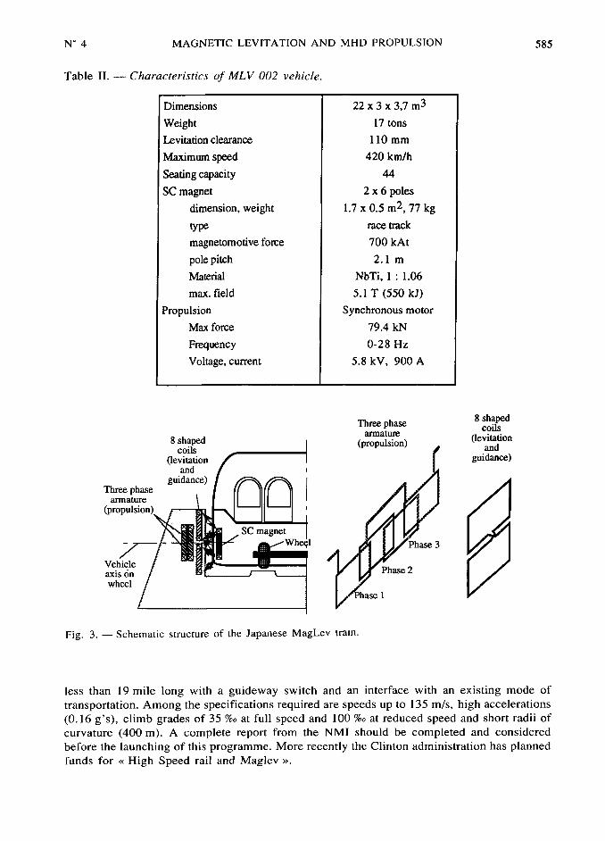
Table II. Characteristics of MLV 002 vehicle.
Dimensions 22 x 3 x 3,7 m3
17 tons
l10 mm
Maximum speed 420 km/h
Seafing capacity 44
SC magnet 2 x 6 poles
dimension, weight 1.7 x 0.5 m2~ 77 kg
type race track
magnetomotive force 700 kAt
pole pitch 2. I m
Matefial NbTi, I : 1.06
max. field 5.I T (550 kJ)
Propulsion Synchronous motor
Max force 79.4 kN
Frequency 0-28 Hz
Voltage, current 5.8 kV, 900 A
~ee~jj~seili~
~~~~~~ ~~~°~~~~°~~ ~~~#~~
(ievitation guidance)and
guidance)Three phase
armature
SC magnet
3~Vehiqle
phase 2
i~~~e~~
Fig. 3. Schematic structure of the Japanese MagLev train.
less than 19 mile long with a guideway switch and an interface with an existing mode of
transportation. Among the specifications required are speeds up to 135 m/s, high accelerations
(0.16 g's), climb grades of 35 %a at full speed and 100 %v at reduced speed and short radii of
curvature (400 m). A complete report from the NMI should be completed and considered
before the launching of this programme. More recently the Clinton administration has planned
funds for«
High Speed rail and Maglev».

586 JOURNAL DE PHYSIQUE III N° 4
Reffigerator
PowerLHe tank lead
LNz tank
Service port
Outer
Support
SC shield
Superinsulator
Persistent current switch
Vacuum
Fig. 4. Cryogenic system (magnet, cryostat and refrigerator) of the Japanese train [5].
Contrary to Japaneses and Germans which are involved in programmes since many years
and have already defined their basic solutions, Americans have no preferential design. This
«clean slate
»provides opportunities for innovative ideas and development of new MagLev
concepts. They consider basic studies about subjects such as magnetic suspension, guidanceand propulsion, power conditioning technologies, power transferring and control, costs,
safety, environmental effects..
Four contracts were issued in 1991 for definition studies of new MagLev concepts. The four
teams (Bechtel team, Grumman team, Magnetplane International team and Foster-Miller
team) have rather different projects, but they all involve using superconducting windings and a
linear synchronous motor for propulsion.The Bechtel group proposes superconducting magnets distributed in the vehicle interacting
with a «ladder track
»for suspension and guidance.
The Grumman team is the only group involved in the electromagnetic levitation with a
design close to the German TR07. Nevertheless the actively controlled iron-pole magnets on
the vehicle are superconducting providing thus a 50 mm air gap (around 10 mm for TR07).
The magnet plane team works on an idea developed in the seventies by MIT [7]. The track
consists in continuous sheet bended into a semi circular arc surrounded the vehicle bottom
which contains superconducting distributed pancake windings. This geometry provides a highride quality due to the possible self banking of the vehicle.
The foster Miller group is involved in the electrodynamic system using coils in the guidewayfor levitation and propulsion and discrete superconducting magnets on board. The supply of the
linear synchronous motor is original in that it occurs only in the vicinity of the vehicle usinghigh speed power electronics switches which improve the motor efficiency.
2. MHD sea-water propulsion.
2.I INTRODUCTION. The first MHD studies were carried out in the United States, duringthe sixties. As shown farther, the need for high magnetic inductions (~ 5 T) in large volumes
(several m~) for the MHD propulsion to be interesting, from an efficiency point of view slowed
its development. The present development level of superconducting winding makes it possible
to consider practically this technology, and numerous programs throughout the world are in
progress. The MHD propulsion offers potential advantages such as high efficiency and speeds,

N° 4 MAGNETIC LEVITATION AND MHD PROPULSION ~87
an enhanced maneuverability and survivability, a better payload flexibility but above all an
increased stealth. The latter explains the military interest in the possibility of building an
undetectable submarine as suggested in the Tom Clancy novel«
Red October».
2.2 PRINCIPLE. The MHD propulsion may be inductive (a.c. MHD) or conductive (d.c.MHD) (Tab. III).
Table III. Coniparison betw.een a-c- and d-c- MHD thrusters.
MHD d.c. MHD a.c.
Itlductor ~no in mode
~~°~~~ d.c. no
low
better lower
Cryogeny very low losses in persistent a.c. losses for superconductors
mode need for current leads
Problems electrodes~ sea water electrolyse superconducting a.c. winding,
reactive be
The a-c- MHD operates as a linear asynchronous electrical motor. Multiphase windings, on
board, create a travelling magnetic field wave in water. Currents are naturally induced in the
conductive sea water and their interaction with the magnetic field propels the ship. The speedof the ship is linked to the speed of the field itself proportional to the frequency of the
multiphase excitation currents. In its principle, a-c- MHD is attractive as it does not use
electrodes in the sea water and solves the related problems. Nevertheless the advantages stopthere. A-c- MHD needs multiphase superconducting windings supplied with variable
frequency currents. These windings have still not yet reached a sufficient degree of
advancement. The total absence of losses in a superconducting winding is only true if the
current is direct and the field around it constant. The eighties have seen the emergence of
superconducting strands with very low a-c. (50 Hz) losses [8]~ but difficulties still remain in
particular, for high current capacity (several kA) cables. Frequencies, for MHD propulsion,would be low (a few Hz) and would reduce the stresses on superconducting windings. but the
losses, though low, significantly penalise the cryogenics in particular the weight and bulkiness
of the helium refrigerator. Moreover the reactive power would be very high (in the order of
109 Var for submarines) and would lead to additional difficulties and problems.The d-c- MHD is based on the interaction between a magnetic induction, created by a d.c.
electromagnet on board, and d.c. current, perpendicular to the field, imposed by a voltagedifference between two electrodes in the conductive sea water. An opposing electromotive
forces appears linked to the ship's displacement. The variation of the current or of the magneticinduction may adjust the propulsion force but basically only the current is controlled as the
superconducting magnets are operating in persistent mode.
The electrodes in the sea water have to fulfil several electrical, mechanical and chemical
requirements for long operating service and at a reasonable cost. Moreover, a partialelectrolysis of the sea water occurs and produces bubbles which are undesirable for reasons of
stealth. The ideal material for electrodes has not yet been found, but studies have been carried
out for carbon, noble metals or compounds like TiRu02, TiIr02..

588 JOURNAL DE PHYSIQUE III N° 4
The power is supplied from Diesel engines, gas turbines or small nuclear reactor. The
electrical power level is some tens MW in present submarines. The huge magnetic energy
stored in the superconducting magnet (several GJ) could serve as an emergency power supplyin case of failure of the main system [9].
As for the a-c- MHD, the d-c- MHD may be extemal (Fig. 5) or internal (flow channelled in
a duct). Nevertheless as one of the interests on this system is its potential for stealth, the
acoustical signature must not be substituted by a magnetic signature which is easy to detect. An
essential characteristic for the excitation magnet would be its leakage field which has to be as
low as possible. Currently the systems with intemal MHD channels are, for this reason, the
most studied systems, as the induction is better confined. The magnetic stealth must be
naturally obtained as active (coils) or passive (magnetic materials) shielding increases the
weight which is already a sensitive parameter. From this point of view the toroidal
configuration is ideal and the systems under study now are close to this configuration with an
annular MHD channel around the hull delimited by the active parts of the magnet and by the
electrodes (Fig. 6).
Elecuode
~~~
Magnefic fieldElecuical flux
field flux disbibufiondisuibufion
Fig. 5. Ship propelled by d-c- MHD (external system).
MHD Thruster
Magnefic field
dis~~~fion ~,, ~j~~t~~d~
'i
"
+,Elecbical ?"~,(,',, '
''~
#$~~~n ~~~~~ ~~~~
Fig. 6. Annular MHD thruster for a submarine.

N° 4 MAGNETIC LEVITATION AND MHD PROPULSION 589
Considering a thrust proportional to the square of the speed, an approximate expression for
the efficiency is given by
~2~ "
~2~
"PV
~MHD
B: magnetic induction, v: speed, p: sea water resistivity, d~~~. MHD volume,magnetic force
"
square of the speedThis expression does not take into account the losses linked to the partial electrolysis of the
sea water. It shows the requirement for a high induction level to a great extent due to the highresistivity of sea water (0.25 Qm, 105
more than Cu) which leads to important ohmic losses in
the water. The efficiency decreases with the speed of the ship. As an example of magnitude for
a speed of 10 m/s, the overall efficiency could reach 60 % and 50 % for magnetic inductions
respectively of 10 T and 7 T but only 18 §b for 2 T. For comparison conventional efficiency is
about 40§b. The present advances in superconducting d-c- magnets make it possible to
consider useful induction levels of 6-7 T with NbTi at 4.5 K, up to 8-9 T with NbTi usinghelium II at 2 K like for the superconducting tokamak Tore Supra [10]. The use of Nbisnwould increase the field 9-10T at 4.5 K. Compounds with transition metals like Nb3Sn,
Nb3Al, Nb3Ge (A15 compounds) have a higher temperature margin compared to NbTi and
may be interesting materials, taking into account the requirements for the magnet (vibrations,impacts) but their technical development is not so advanced except for Nb3Sn and their use is
more difficult than with NbTi. The induction level is not the only parameter to consider. This
induction level and the volume to be magnetized lead to huge amounts of magnetic energy of
the order of one tenth of a10~ J for submarines, and then to huge mechanical stresses. The
mechanical structure has to be strong to resists to these forces very rigidly. As a matter of fact
the displacement, even micrometric, of a superconducting strand in a magnetic field may lead
to its quench which has to be absolutely avoided. For embarked materials, especially for
military uses, these stresses are enhanced by the need to fulfil impacts. Moreover this structure
must be light and must assume a neutral buoyancy. The realization of lighweight high field
magnets would be one of the challenges for MHD technology. The prejent techniques usingsteels are too heavy in the intemational project on nuclear fusion ITER the toroidal coils
would have a structure weight of 10 000 tons including 770 tons of superconducting materials
but without the cryostat vessels (6 T on the toroidal axis, 13 T peak on the superconductor and
a magnetic energy of 106 GJ). The theoretical limits are nevertheless high. The virial theorem
links the magnetic energy to the mass of coil structure by the expression [I1]
~W~
~~ _~~~~
P~
W~~~. magnetic energy, «~. allowable stress, p: density, M~: mass in tension,
M~ mass in compression.Assuming a structure is only in tension, the theoretical limit of the magnetic energy by mass
unity is given by the specific energy «~/p of the structural materials. Graphite epoxy
composites offer much higher values than classical steels : 150 kJ/kg compared to 30 kJ/kg.
For comparison, present superconducting magnets have a specific energy of the order of
10 kJ/kg. A value of 50 kJ/kg may be achievable in a near future [I I].
As for MagLev vehicles, the magnetic induction, constant in the ship referential, may be
created by superconducting magnets operating in persistent mode that is to say, short
circuited coils. After the magnet has been energized by a current from a power source and after
the magnet terrninals have been shorted out with a superconducting link, the power supply may
590 JOURNAL DE PHYSIQUE III N° 4
be suppressed and the current leads may be removed. The persistent mode is very interesting as
the current lead losses are a major part of the total cryogenic losses. In these conditions, the
power of the helium refrigerator on board may be very low if the cool down is carried out on
land.
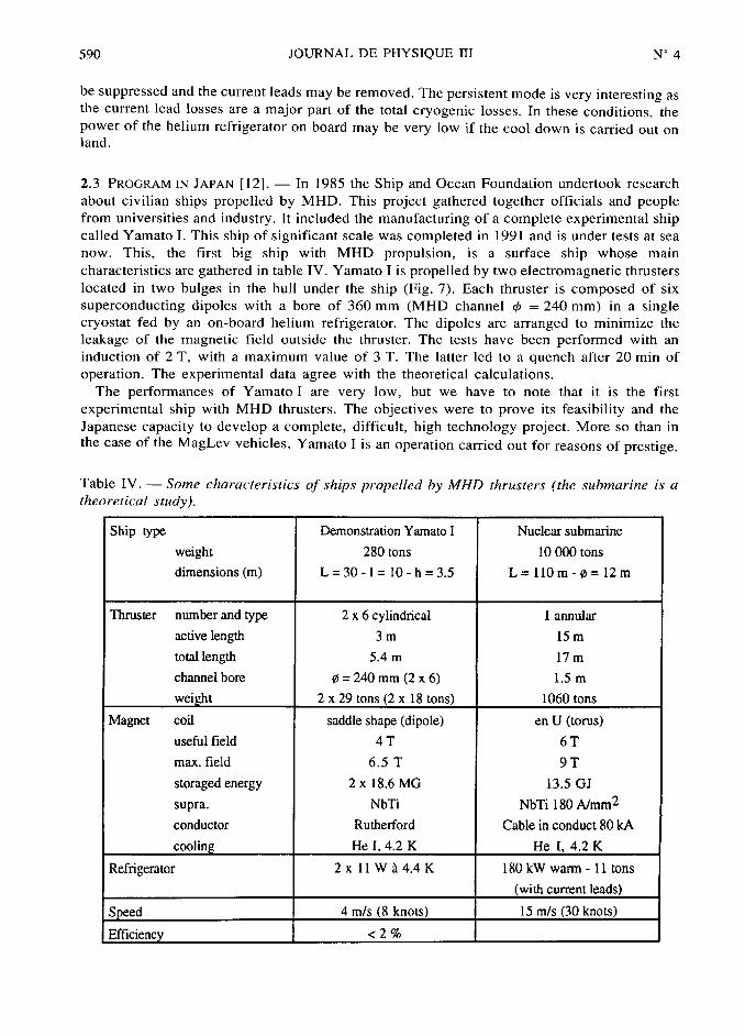
2.3 PROGRAM IN JAPAN [12]. In 1985 the Ship and Ocean Foundation undertook research
about civilian ships propelled by MHD. This project gathered together officials and peoplefrom universities and industry. It included the manufacturing of a complete experimental shipcalled Yamato I. This ship of significant scale was completed in 1991 and is under tests at sea
now. This, the first big ship with MHD propulsion, is a surface ship whose main
characteristics are gathered in table IV. Yamato I is propelled by two electromagnetic thrusters
located in two bulges in the hull under the ship (Fig. 7). Each thruster is composed of six
superconducting dipoles with a bore of 360 mm (MHD channel ~b =
240 mm) in a singlecryostat fed by an on-board helium refrigerator. The dipoles are arranged to minimize the
leakage of the magnetic field outside the thruster. The tests have been performed with an
induction of 2 T, with a maximum value of 3 T. The latter led to a quench after 20 min of
operation. The experimental data agree with the theoretical calculations.
The perforrnances of Yamatol are very low, but we have to note that it is the first
experimental ship with MHD thrusters. The objectives were to prove its feasibility and the
Japanese capacity to develop a complete, difficult, high technology project. More so than in
the Case Of the MagLev vehicles, Yamato I is an operation carried out for reasons of prestige.
Table IV. Some characteristics of ships propelled by MHD thrusters (the sabmai"ine is a
theoretical study).
Ship type Demonstration Yamato I Nuclear submarine
weight 280 tons 10 000 tons
dimensions(m) L=30-1=10-h=3.5 L= I10m-#=I2m
Thruster number and type 2 x 6 cylindrical I anttular
active length 3 m 15 m
total length 5.4 m 17 m
channel bore #=
240 mm (2 x 6) 1.5 m
2 x 29 x 18 1060 tons
coil saddle shape (dipole) en U (tortls)
useful field 4 T 6 T
max. field 6. 5 T 9 T
storaged energy 2 x 18.6 MG 13.5 GJ
supra. NbTi NbTi 180 A/mm2
conductor Rutherford Cable in conduct 80 kA
He 4.2K He 4.2K
2 x I I W 14A K 180 kW warrr I I tons
4 m/s 15 m/s
<2ib

N° 4 MAGNETIC LEVITATION AND MHD PROPULSION 591
'-'f'-
'4
-.~j,Y[$ <I''$- "~.0$'-'~
i~/,'_'
j',I'll f
n"-'.~]j~~~-'& 2j~~,
i~
Fig. 7. Yamato I, MHD ship (Height : 3.5 m, Width lo m, Length 30 m).
2.4 PROGRAMS IN THE UNITED STATES. The first studies of MHD were carried out in the
United States in the sixties, but were later interrupted. Since then naval research into
propulsion has concerned the classical propulsion, but using superconducting motors (inparticular the experimental ship Jupiter II with a homopolar superconducting motor of
2.2MW). Programs about MHD were re-continued at the end of the eighties. They are
financed by DARPA (Defence Advanced Research Project Agency) and the Naval Research
Technology Office. These programs should provide a better theoretical knowledge of MHD
phenomena and some tests on the key points. The experimental tests use the flow loops at the
NUWC in New Port, or at Argonne National Laboratory with a large Superconducting magnet.The description of a MHD submarine project [9] (Tab. IV) enables the definition of some of
the major points.
2.5 PROGRAM IN C.E.1. [13]. The Russian are certainly involved in important programmes
themselves. They are studying in particular a solution of d-c- MHD with a special geometryusing a solenoid magnet with a screw MHD channel inside. The advantages of this
configuration are simplicity and the light weight of the magnet system, but the hydraulic and
Joule losses are heightened compared to classical duct channels. The real system is composedby two concentric solenoids for active magnetic shielding with two screw channels.
2.6 PROGRAM IN FRANCE [14]. France is interested in MHD studies. A centre for
applications of MHD called PAMIR has been created throught co-operation between a
laboratory (LEGIfIMG) the C.E.A (Commissariat h l'dnergie Atomique, CEN Cadarache) and
two industrials (Framatome and DT21). The objective of PAMIR is the development of
industrial applications of MHD, but not, for instance, of propulsion. A program has been
issued by the DRET (Direction des Recherches Etudes et Techniques de la DdldgationGdndrale pour l'Armement), involving Jeumont Industrie and four laboratories in Grenoble
(LEGI-IMG, Madylam, CREMGP and LEG). This program will attempt to carry out generalstudies on the systems fluid mechanics aspects (flow in MHD duct, evaluation of drag

592 JOURNAL DE PHYSIQUE III N° 4
force~ .), numerical modelling with coupling between fluid mechanics and electromagnetism,taking into account the non uniform distribution of majnetic fields, electrochemical aspects
(seawater properties, electrodes, phenomena modelling, ), superconducting magnets
(configuration and shape, magnetic signature and its reduction, magnetic shielding), overall
performance prediction. An experimental programme is carried out especially for electrochemi-
stry studies using a seawater laboratory close loop (electrolysis, corrosion of electrodes, gas
production~ ).
3. Refrigeration on board.
There are two solutions to keep the superconducting magnets at low temperature. Either a
sufficiently large amount of liquid helium may be stored on the vehicle between two fillings, or
a helium refrigerator on board may provide the cryogenic losses. The first solution, of
minimum weight for the vehicle, provides a high efficiency, large capacity liquefaction in
large plants, but requires skilled persons to carry out the transferts and brings constraints and
operational complexity. It cannot be applied to MHD ships. If the cool down is made by a land-
borne large capacity system, the helium refrigerator required for the superconducting MHD
magnet does not pose any problems for submarines (for example from Tab. [Vi the power
amounts to some hundreds of watt (depending on the presence, or lack of it, of current leads).
It corresponds to a system whose weight and volume are, respectively, roughly 5 to 10 tons
and 10-15 m3 ; low figures compared to those for the~ submarine (10 000 tons and 12 000 m~).
On board refrigerators for MagLev vehicles are much more flexible, but this requires the
developement of small unit helium refrigerators with low weight and bulkiness, very highreliability and which are less sensitive to vibrations. Such systems have been developed for
satellites but for very small power (lower than I W to cool, for example~ detectors) and are not
always suitable for a levitated vehicle (power too low). Japanese researchers developed such a
helium refrigerator [15] in 1979 and have since obtained some interesting performances.
Conclusion and perspectives.
MagLev vehicles and MHD are two possible applications of superconductivity. MagLev
systems may be designed with conventional magnets but several people think that you cannot
get good MagLev without superconductivity. Japanese MagLev trains have already reached an
advanced degree of demonstration. Superconducting MagLev system is feasible from technical
point of view but its challenge is to prove its economical interest compared to high speed trains
except if speeds higher than 400 km/h are absolutely required.For MHD there is no altemative to superconductivity as large volumes must be magnetized
at high fields to get suitable performances. The studies have often stayed at the stage of
theoretical designs whereas the first MHD ship of significant size, Yamato, shows very low
performances. Nevertheless MHD propulsion offers an innovative solution with significantbenefits. The increased stealth is perhaps one of the most interesting improvements if the
magnetic signature may be reduced to a very low level. A lot of research and development are
still needed to study and to solve the numerous difficulties related to MHD thrusters. One
technical bolt is the superconducting magnet with a light mechanical structure able to
withstand electromagnetic forces and impacts.Superconductors with a high critical temperature would not greatly modify the structure of
the magnets or of the cryostat except, of course, for a few simplifications. They will bringnevertheless a large gain for the refrigerator at a given power, the weight and the volume of
the nitrogen refrigerator are divided roughly by fifty compared to a helium refrigerator.Another advantage of the high T~ materials for moving systems is their much higher stability

N° 4 MAGNETIC LEVITATION AND MHD PROPULSION 593
margin, as well as lower sensitivity for impacts, vibrations and a-c- losses. These supercon-
ducting oxides offer the opportunities of higher fields but limitations due to the electromagnetic
stresses will occur.
Acknowledgments.
This study has been made within the framework of co-operation between the DGA (DdldgationGdndrale pour l'Arrnement) and Jeumont Industrie. I would like to thank MM. J. P. Thibault,
C. H. Kom et Y. Brunet for their valuable discussions.
References
[Ii Moreau A., Le contact roue-rail, Revue gdndrale des chemins de fer (uillet-ao0t 1991) 43-51.
[2] Takahashi T., Maki N., Miyashita T., «Combined system for propulsion and guidance of
magnetically suspended vehicles », Proceedings of the fifth Intemational Cryogenic Enginee-ring Conference (1974) 78-81.
[31 Shibata M., Maki N., Saitoh T., Kobayashi T., Sawano E., Ohshima H., On board power supply
system of a magnetically levitated vehicke, IEEE Trans. Magn. 28 (1992) 474-477.
[4] Fujie J.,«
Current status of MagLev transportation system in the world », Proceedings of the
eleventh Magnet Technology Conference, Tsukuba-Japan (1989) 9-17.
[5] Tanaka H., Advanced Materials for Magnetically Levitated Trains, Q. Rep. RTRI 33 (1992) 160-
l65.
[6] Coffey H. T., U-S- MagLev : status and opportunities, IEEE Trans. Appl. Sapercondactii,ity 3
(1993) 863-868.
[71 Iwasa Y., Hoenig M. O., Kolm H. H., Design of a full scale magnetplane vehicle, IEEE Trans.
Magn. lo (1974) 402-405.
[81 Dubots P., Fdvrier A., Renard J. C., Goyer J. C., Ky H. G., Behaviour of multifilamentary NbTi
conductors with very fine filaments under a-c- magnetic fields, J. Phys. Fiance 45 (1984) 467-
470.
[9] Swallom D. W., Sadovnik I., Gibbs J. S., Gurol H., Nguyen L. V., Van Den Bergh H. H.,
Magnetohydrodynamic submarine propulsion system, Naval Eng. J. (May 1991), 141-157.
[10] Duchateau J. L., Bessette D., Ciazinski D.~ Pierre J., RibandP., Turk B., Monitoring and
controlling TORE SUPRA toroidal field system status after a year of operating experience at
nominal current, IEEE Trans. Magn. 27 (1991) 2053-2056.
I II Leung E. M. W., Hilal M. A., Parmer J. F., Peck S. D., Lightweight magnet for space applications,
IEEE Trans. Magn. 23 (1987) 1331-1335.
[12] Motora S., Imaichi K., Nakato M., Takezawa S.,«
An outline of the R&D project on
superconducting MHD ship propulsion in Japan »,Proceedings of MHDS 91.
[13] Bashkatov V. A., Mikhailova L. A.,«
Investigation of electrolyte screw MHD flows and their
application in development of ship jet engines for commerce », 7th Bur Sheva Seminar on
MHD Flow and Turbulence (Febrtlary 93).
[14] Thibault J. P., Alemany A., Pilaud A.,«
Some aspects of seawater MHD Thrusters », Proceedings
of MHDS 91, 211-218.
[15] Nakashima H., Herai T.,«
The cryogenic system for magnetic levitation vehicles », Proceedings of
MagLev'89 (1989) 235-239.
![EXACT SOLUTION OF MAGNETO-HYDRODYNAMIC SYSTEM … · metals, MHD power generation and propulsion [14, 15]. Despite its apparent simplicity, MHD describes a remarkably rich and varied](https://img.dokumen.tips/doc/110x75/5f0316207e708231d407778d/exact-solution-of-magneto-hydrodynamic-system-metals-mhd-power-generation-and-propulsion.jpg)


![CHAP04. PLASMA DISPLAY PANEL - …121C771E4C273B84482… · PLASMA DISPLAY PANEL ... ¾역학적: 전자기력의발생[MHD 발전, plasma propulsion] ¾화학적: ... PDP의효율의개선방향](https://img.dokumen.tips/doc/110x75/5b8e444b09d3f2a0138d3e3c/chap04-plasma-display-panel-121c771e4c273b84482-plasma-display-panel-.jpg)