Embed Size (px)
Citation preview
466 J. SPACECRAFT VOL. 13, NO. 8
MHD Propulsion by Absorption of Laser RadiationL. N. Myrabo*
University of California at San Diego, La Jolla, Calif.
The conceptual design for a laser-riding air-breathing single stage shuttle which would usemagnetohydrodynamic (MHD) forces to accelerate the engine working fluid is introduced. A gigawatt power-level photon beam delivered from an orbital laser power station is focused by the shuttle craft onto internalengine working fluid to create, within an annular ionization chamber, a confined air plasma stationary wave.Free electrons are immediately pumped from the plasma and ejected into the external slipstream at the perimeterof the machine. The remaining positively charged working fluid is accelerated by gasdynamic expansion and thepinch-plasma effect, and discharged at a rear nozzle. The vehicle slipstream, now negatively charged and con-ducting, interacts with a concentric positively charged plasma core to provide quasi-steady flight propulsiveforces in an externally-excited-field MHD accelerator. Continuous MHD engine electric currents in the nearmegampere range are attained through the use of: a) remote power ionization of engine working fluid, and b)electron beam space-charge neutralization techniques reported in recent literature on fusion research. A cursoryexamination of the required laser power, thrust, exhaust velocities, electric current, and working fluid electricalconductivity reveals operable engine parameters in an interesting range indicating that the system may be worthyof further examination.
I. Introduction
WITH the current interest in high-energy orbitallaser power stations, space missions heretofore thought
to be impossible are now demanding renewed examination.Exotic new propulsion systems comprised of remote laserpower stations, high-energy transmission optics, andpropulsion converters at the vehicle receptor site may soon bepossible. The tasks of building large laser power stations inspace or on Earth, and of transmitting the power appear to beaccomplishable.!"7 However, a new converter technology isneeded since this final system component is now recognized asbeing the weakest link.7 Consequently, two recent con-ferences on laser energy conversion have been sponsored bythe NASA Ames Research Center, focusing on the majorenergy conversion forms: electrical, shaft horsepower,storable chemical, and propulsion.7'8 This paper concerns it-self with the latter, in a largely unexplored liaison of remotelaser energy with magnetohydrodynamic (MHD) generation.
The potential for application of MHD generation topropulsion of nuclear/electric submarines in an ocean plasmahas already received the attention of researchers.9"19 The firstexperimental verification of a self-sufficient system was ac-complished by S. Way on July 21, 1966, with a 10 ft modelsubmarine powered by lead-acid batteries.I5 A number ofanalogous schemes for hybrid nuclear/electric spacepropulsion have been proposed with both open and closedthermodynamic cycles.20"29 Most of these, however, havegreat difficulty showing performance gains large enough tojustify the additional complexity and weight beyond a strictlynuclear rocket.27 A possible exception is the more recent workof R. J. Rosa,27'29 who suggests that when flying in an at-mosphere, it might be possible to advantageously employ airaugmenting, i.e., the use of some or all the electric output ofthe generator to drive an electric ramjet.29 As an entertainingsuggestion, Rosa proposes an extension of this scheme, whichhe dubbed the ''MHD Lift Fan,"30 an airbreathing spaceshuttle which would propel itself on lightweight high-powerchemical batteries. He suggests that the craft might berecharged midflight by beaming energy from an orbitaloperations base.
Presented at the San Diego Section A1AA Students'Technologyfest, San Diego, Calif., April 29, 1975, and at the RegionVI AIAA Student Conference, Stanford, Calif., May 1-2, 1975; sub-mitted May 15, 1975; revision received March 12, 1976.
Index categories: Electric and Advanced Space Propulsion; PlasmaDynamics and MHD.
*UCSD Energy Center Research Assistant. Member AIAA.
Other serious attention in the past has been given to usingthe high altitude planetary atmosphere to propulsive ad-vantage in both chemical and electrical systems. The work ofS. T. Demetriades, the "Air-Scooping Orbital Rocket (A-SCOR)," has been the most exhaustive.31"34 Similar studieswere carried out by other investigators. 35~39 It was determinedthat a large local power source of perhaps several megawattscapacity would be required to assist in the cryogenicpropellant collection function, as well as in chemical or elec-trical heating of propellant in the thruster. Recent work byG. L. Cann, "The Space Electric Ramjet (SERJ)," explores arelated solar powered scheme unencumbered with cryogeniccollection.40'41
Clearly, the performance of these propulsion schemeswould be greatly enhanced if they were somehow relieved oftheir weighty self-contained energy sources. The laser holdsgreat promise for accomplishing this in space propulsion, asevidenced by much current literature on the subject.42~49 Theassociated propulsion converters have largely been envisionedto use the remote laser power to heat on-board propellant(hydrogen), which is then expanded through a rocket nozzle.One exception which proposes to use the planetary at-mosphere to advantage is the "Laser Powered Pulse-Jet,"45'49
although its application as an orbital shuttle craft may belimited due to the unavailability of sufficient quantities of airrequired for successful operation at the higher altitudes withthe expected range of engine exhaust velocities.
Several perceived problems with the ground launched laser-heated rocket systems have been mentioned.48 One having farreaching economic consequences is that several power stationsdistributed along the launch trajectory must consecutivelypower the shuttle craft. It is anticipated that each ground-based power source must supply a hundred gigawatts (1GW=109W) or more of peak power, indicating very largefixed systems costs.48
Stuhlinger and others have considered certain space-basedcycles for converting remote laser energy into electric energyand electrostatic acceleration of ionized propellant.20'50'51
However, no propulsion converter research has as yet beenmentioned or proposed in the literature, which would use boththe powerful air-plasma generating capabilities of a high-energy laser power source and the high temperature shock-ionized air plasmas naturally occurring with hypersonic flightthrough the atmosphere. Therefore, the examination of MHDgeneration for application in an air-plasma breathing laserpropulsion converter appears appropriate. The liaison holdsgreat potential for propelling space shuttle craft into orbit
Dow
nloa
ded
by M
ON
ASH
UN
IVE
RSI
TY
on
Febr
uary
3, 2
015
| http
://ar
c.ai
aa.o
rg |
DO
I: 1
0.25
14/3
.279
19
AUGUST 1976 MHD PROPULSION BY ABSORPTION OF LASER RADIATION 467
with an essentially infinite specific impulse, especially con-sidering that MHD thrusters are known for their ability toproduce the very high exhaust velocities required for realisticair-breathing propulsion at high altitudes.52"54 The schemebecomes even more attractive when it is realized that higherpropulsive efficiencies may allow a single orbital laser powerstation, perhaps attached to a space laboratory or colony,55
to supply only several gigawatts of power. On a close fly-byorbit, radiant energy would be transmitted to the planetarysurface, the shuttle craft "beamed-up," and docking in orbitwould occur several thousand miles downrange. We shall nowdescribe such a system.
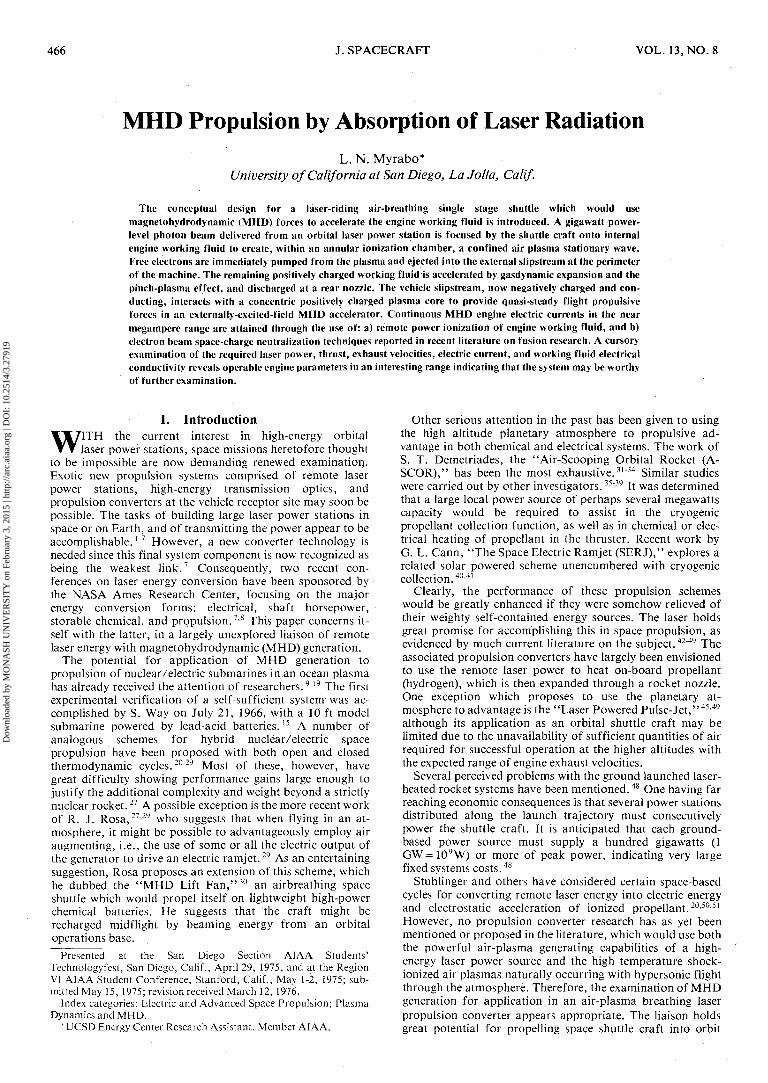
II. Physics of Engine ConceptIllustrated in Fig. 1 is a functional diagram of the
LASER/MHD propulsion converter concept shown in-timately integrated with a compact shuttle craft airframe. Itsmaximum diameter is arbitrarily set equal to that of theSaturn V launch vehicle. A laser power station first transmitsradiant power to the engine receptor site. As shown in Fig. 1,the beam is received by a mirrored upper superstructure, andthen reflected and concentrated into an annular intake whoseinterior surfaces are also mirrored to enhance propagation ofthe beam down the passages. The radially partitionedpassages provide an additional centrifugal compression func-tion for pressurizing engine air entering the same annularopening.
Immediately upon entrance to the ionization chamber at theradial location denoted in Fig. 1, small beams of electrons areinjected into the internal engine working fluid triggering in-verse Bremsstrahlung absorption of this laser energy.56"58
Substantial laser-induced electrical air breakdown (ionization)is anticipated at this time transforming the internal engineflow into a dense air plasma.59"61 Radiation not absorbed inthe gas will probably reflect downstream off the passagewaywalls heating the nozzle throat where heat transfer could be amajor limiting factor to successful operation of the engine.56
Within the annular ionization chamber, a large number ofdiodes (e.g. several hundred) are evenly distributed about thevehicle rim. Each diode would be composed of two parallelflat plate electrodes with a small diameter hole in the anode(perhaps 1-2 mm diam) which would vent to the atmosphereat the rim of the machine. Application of a high voltage(i.e. ~ 1 MV) across a diode for a very short time period (i.e.,many n/sec) would result in the extraction of a high currentbeam pulse (e.g.~l MA) from the internal fluid plasma,62
followed by injection of that beam into the external vehicleslipstream. At the proper external electron seed fraction (i.e.,about 0.1% injection "seed" electrons), the entire vehicleslipstream becomes a conducting air plasma, since it now con-tains a great quantity of highly mobile free electrons.29'63 Thekinetic energy of these electrons is subsequently increased bycollisions with the slipstream air molecules as they are bothswept downstream. The vehicle slipstream next to the diodewould probably still contain a high electron population at thetime of the next injection cycle.
An important background plasma function, which has beenexperimentally observed, is to provide an ion background ofsufficient magnitude to help neutralize the electrostatic spacecharge which would build up along the electron beam axis(i.e., positive ions from the background plasma will be pulledinto the beam center).65"66 A second plasma function involvesmagnetic neutralization of the self-field (i.e., generated by thebeam itself), which if not checked, may prematurely pinch offthe propagating beam before the charge is completely ejec-ted.66'68 The anti-pinch phenomena, also observed ex-perimentally, may be explained by assuming that the self-field, which would be generated, is cancelled by large numbersof slowly counter-streaming electrons in the backgroundplasma.67
This electron beam discharge would pull a small percentageof electrons (e.g., 1-2%) from the available ionized molecules
SHOCK WAVEANNULAR INTAKE
CENTRIFUGAL COMPRESSION(SUBSONIC FLIGHT)
FREE STREAM IVELOCITY V 33 1
J X B BODY FORCES |y j X B BODY FORCES
•Y
Fig. 1 Laser/MHD propulsion converter concept.
leaving the previously neutral internal working fluid with anet positive charge. The positively charged plasma will expandfrom the ionization chamber through the throat and into anadjustable blade-pitch turbine (or an equivalent sub-system),imparting the entire vehicle with the rotational velocityrequired for proper operation of the centrifugal compressor.tAs this positively charged plasma continues to gas-dynamically expand down an intern'al nozzle, it shielded frommixing, and hence, from recombining with the externalnegatively charged slipstream shown in Fig. 1.
Reference to the MHD thruster configuration in Fig. 1 (i.e.,the aft portion of the vehicle), suggests several distinct dif-ferences in arrangement from that of traditional MHD arc-jets described in the literature. First, the large diameter "rim-electrode" is negative (cathode) rather than positive; andsecondly, it is placed upstream rather than downstream of thesmaller diameter "central-electode," which in this case is theanode. A final major difference is that the anode exudes apowerful beam of positive ions, while the cathode emitsradially symmetric streams of electrons.
The external vehicle slipstream would be accelerated usingthe volume energy addition mechanism of MHD generation inthe following manner. The MHD thruster first showers freeelectrons from the periphery into the external vehicle slip-stream to create an electrically conducting medium, acquiringin the process, a net negative space charge. Simultaneously,the thruster ejects a powerful beam of positive ions from acentered downstream nozzle. The presence of separatedcharge of opposite sign generates a strong radially symmetric,outward directed electric field within the exhaust plume. Sincethis charge is moving with respect to the machine, anazimuthally directed magnetic field is generated within thesame toriod-shaped nozzle region. The field completely closesupon itself within the exhaust gases yielding a highly efficientacceleration mechanism, typical to high current MHD arc-jetthrusters. Interaction of these crossed electric and magneticfields drive the conducting gases aft within the MHD 'nozzle'region in accordance with the following relation:
> > >Fm=JxB (1)
wher| Fm is the magnetic body force, J is the current density,,and B is the self-induced magnetic field. Effective slipstream'exhaust' velocities, Vef, are attained just downstream of theregion of significant electromagnetic interaction when thesegases again become electrically neutral.fThe compressor, which forms an integral part of the upper vehiclesuperstructure, must provide a positive pressure ratio against whichthe higher ionization chamber pressures may do work on the internalengine working fluid, accelerating it after heat addition. At supersonicflight speeds, however, when ram air provides this function, the tur-bine blade pitch would be reduced to zero and the vehile would ceaseto rotate.
Dow
nloa
ded
by M
ON
ASH
UN
IVE
RSI
TY
on
Febr
uary
3, 2
015
| http
://ar
c.ai
aa.o
rg |
DO
I: 1
0.25
14/3
.279
19
468 L.N. MYRABO J. SPACRARAFT
The detailed mechanism for self-field acceleration is todaystill inadequately understood, but is known to be theprimarily responsible accelerating agent in ,the small ex-perimental MHD arc-jet engines when the current range is ex-tended beyond 2000 A.69'70 Jahn52 describes the MHD arc-jetas being a renegade violating our estimates of reasonablevalues for current density from an electrode, gas density, gastemperature, channel length, channel profile, gas con-ductivity, and magnetic interaction parameter. Furthermore,Jahn52 suggests it is a device fortuitously embodying in-tensities and geometries of current and electric and magneticfields which circumvent several of the classical limitations ofthe conventional electromagnetic and electrothermal ac-celerators.
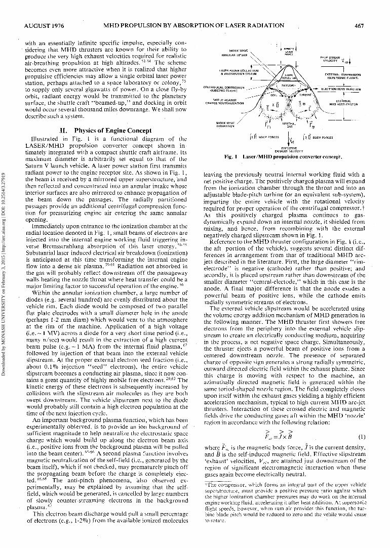
We can, however, extract a certain amount of qualitativeinformation about the proposed thruster operation byexamining the following expressions for the self-magneticfield and the related gas-kinetic pressures originating withinan electrical current configuration assumed to be an idealtoroid, for the sake of analytical simplicity. Figure 2 illustratesthe toroid section properties for gas-kinetic pressure, P(r),current density, 'j(r), and magnetic induction field, B(r),along an arbitrary radial line A—A' which intersects thecentral toroid axis of radial symmetry. Also pictured in Fig. 2is a segment of the positive-ion plasma-beam, the only portionof the complete toroid electric charge flowfield mechanicallyconstrained by physical boundaries. The magnetic inductionfield within an ideal toroid is:
DIRECTIONOF FLIGHT
B=(fjLi/2irr) (2)
for r3<r<r4 in Fig. 2 where /z is the magnetic permeability, /is total engine current, and r the radial distance from thetoroid central axis. Anywhere outside the toroid, the magneticinduction field will be zero (i.e., r2 > r> r4 in Fig. 2).
The gas-kinetic *'pinch" pressure across any nozzle cross-sectional area S (pinch direction as shown) is:
=(ni2 cosO)/S (3)
for 0<0<90° in Fig. 2, where 6 is measured as shown from ahorizontal plane perpendicular to the axis of radial symmetry.
As the result of Eqs. (2) and (3), positive charge, in theform of discrete high current pulses, will expand down theaerodynamic plug nozzle with increasing supersonic velocityand see an increasing self-magnetic field inversely propor-tional to the shrinking plasma tube radius. Simultaneously,the moving charge generates a gas-kinetic pressure tending to'pinch' the beam out of its plug nozzle. At the exhaust nozzleexit plane (see Fig. 1), the positive-ion plasma-beam will stillbe constricting toward its central axis. After exiting from theengine at a high velocity, the ion-beam may tend to sup-plement the MHD acceleration process by helping to ac-celerate the external, higher mass flow rate, conductingplasma slipstream in the manner of an MHD ejector.71
Having left the nozzle exit, the beam is no longer hollow,and the internal magnetic induction field may be expressed as:
o _ (4)
for r<r} in Fig. 2, where rl is the radius of the ion-beamedge. The associated gas-kinetic 'pinch' pressure52 within theion-beam is:
p=(<jrj2/4) (r2,-r2) (5)
for 0« 0 in Fig. 2, where/?/ is the ambient gas pressure outsidethe beam edge r,.
The generation of the enclosed segment of the positive ion-beam, therefore, is the most responsible agent for acceleratingthe external conducting vehicle slipstream; the thrust is com-
Fig. 2 Self-magnetic fieldand gas-kinetic pressureswithin the MHD thruster.
municated by means of self-magnetic fields of this ion-beamsegment. The exhaust gases, of course, similarly repel thepositive ion gases which in turn, push against the upper in-ternal nozzle passageways generating flight-directed gas-kinetic pressures, viz;
sinO)/S (6)
for 0<0<90° in Fig. 2. It is evident that any significant in-terruption of a radially uniform diode 'firing' pattern wouldresult in a lifting of the favored side of the thruster, or in alateral displacement of the vehicle, depending on thrustergeometry. This condition would disrupt the MHD currentgeometry from a completely enclosed toroid discharge patternto an open one more closely resembling the less efficient'button-type' or 'rail-type' accelerators.52
An analysis of the energy balance within the proposedthruster scheme reveals the necessity for replenishing thesignificant losses suffered by the engine during electron beamejections at the "rim-cathode." One method by which theseloses may be regained would be to integrate into thepropulsion system an inductor-capacitor (LC) circuit excitedby the intense changing magnetic fields at the plug-nozzle exit.Equation (2) requires that the strongest self-magnetic fieldsoccur at this minimum radial location. An excitation coil (seeFig. 1) will be exposed to an increasing field upon approach ofthe ion pulse, and to a diminishing field as it exits the nozzleopening. Because of the large pulsed energy requirements forextracting electron beams at near relativistic velocities andmegampere peak currents, both inductor and capacitor com-ponents are likely to be large. For the purposes of this study, asample calculation was carried out assuming the entire vehiclestructure (excluding upper centrifugal compressor passagesand the lower external charge neutralization shield) was toserve as one large ceramic dielectric capacitor. A dielectricmaterial thickness of 1 cm (metalized on both sides) wasassumed, as was an energy density of 0.2 J/cm3 (this energydensity agreeing well with that proposed in a paper byWinterberg72) and a total capacitator area (as estimated fromvehicular dimensions in Fig. 1) of 219 m.2 The calculationrevealed that the maximum charge stored in such a capacitorwould be 1.3 C, while vehicle capacitance may reach 1.9 /zFand the total stored electrical energy 4.4 x!05J. (Otherpossible solutions to the charge storage problem are available,however. In a recent paper, H. Alfven reminds us that a thun-dercloud can store 10 to 50 C. He then suggests that if anelectric powered shuttle is furnished with a number of sharppoints, it could distribute charge through corona discharges toa vast region around it where the charge can be stored.73)Because of the large quasi-steady MHD engine electric cur-rents required for peak thrust, the LC circuit will probablyoperate in the near megacycle frequency range.
Other possibilities to be explored for filling the 'electronbeam extraction' energy deficit must certainly include theTELEC.7 This laser energy converter requires inverseBremsstrahlung absorption to provide heated plasmas for
Dow
nloa
ded
by M
ON
ASH
UN
IVE
RSI
TY
on
Febr
uary
3, 2
015
| http
://ar
c.ai
aa.o
rg |
DO
I: 1
0.25
14/3
.279
19
AUGUST 1976 MHD PROPULSION BY ABSORPTION OF LASER RADIATION 469
direct conversion to electricity. Hence, it is ideally suited forliaison with the proposed propulsion scheme, hereby ex-panding into a hybrid laser/electric/MHD cycle. TheTELEC, which at best is expected to be 45% efficient, isclosely related to a type of thermionic //converter developedby Waymouth.74
The following expression for the thrust of self-magneticfield MHD arc-jet engines, expressed as a function of current,engine geometry, and total 'chamber' pressure has been in-troduced by Hu'gel, Kruelle, and Peters,60'70 and will be usedin this analysis of the MHD shuttle:
where / is the accelerator electric current, /x the magnetic per-.meability, dc the diameter of the 'rim cathode,' da thediameter of the positive-ion plasma-beam at minimum'pinched' dimension, CF the aerodynamic thrust coefficient,P0 the total 'chamber' pressure, and A* the nozzle throatarea. Total theoretical thrust may be expressed as the sum oftwo major components. The first term is the thrust resultingfrom magnetic effects, while the second is generated by ther-mal or aerodynamic effects. A ratio of dc/da equal to 10 ischosen for this analysis implying that the positive-ion plasma-beam will 'pinch' to a minimum diameter of 1 m. Thrust con-tributions from aerodynamic or thermal effects will beignored.
III. Engine and Vehicle PerformanceThe shuttle craft pictured in Fig. 1 is envisioned as a single
stage air-breathing orbital machine which uses to greatest ad-vantage not only the air-plasma generating capabilities of thelaser beam power source, but also the high temperatureshock-ionized air-plasma associated with hypersonic flightthrough the atmosphere. Since no fuel is burned, the fuelspecific impulse of the engine is infinity. Energy is not addedto the engine working fluid by conventional gasdynamic andcombustion means, but by MHD body forces acting on the en-tire external slipstream passing through its 'nozzle' region.Hence, many problems associated with combustor inlet tem-perature restrictions on the maximum allowable heat additionto the flow, supersonic combustion, and inherent necessity ofa long hypersonic engine geometry are eliminated. At highMach numbers, thermodynamic heat transfer and vehicularcooling requirements become increasingly important. Sincethese problems are functions of vehicular wetted area exposedto the high temperature flow, a low lift to drag ratio (L/Z)),compact type of air-breathing vehicle is desirable. In thesupersonic flight regime, it is conceivable that wave dragcreated by a strong vehicle bow shock can potentially beeliminated, or at least greatly reduced, by MHD accelerationof the slipstream. As illustrated in Fig. 1, the shock mayinitially help direct expansion of the 'exhaust' gases aft priorto dissipation, saving an enormous amount of propulsiveenergy. At hypersonic speeds, significant electron densitiesforming in the shock-ionized slipstream will begin topenetrate the MHD 'nozzle' region. This phenomenon is ex-pected to significantly increase electrical conductivity of theflow and, hence, the efficiency of the accelerator.
Because of the appearance of a plentiful shock-ionized air-plasma at the near orbital velocities, the engine may be able tosustain altitude with a relatively low power input. The vehiclemay also be able to trade 'potential energy associated withheight' for independently generated maneuvering forcesduring orbital reentry75 until such a time when it will require aburst of remote laser power for breaking and touchdown. Forsimplicity, the vehicle should have no moving parts (exceptperhaps variable pitch turbine blades, unless replaced by anequivalent system, and a bearing supported payload module).Since the vehicle propulsion system produces intense rapidlyfluctuating magnetic fields, extensive use of ceramic or other
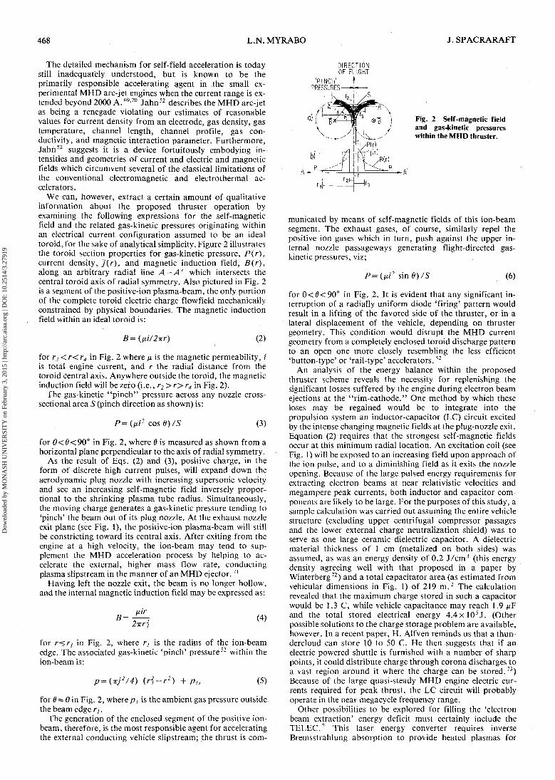
Fig. 3 Drag powerdissipation along ex-trapolated orbital trajec- Q _tones. ?«J 60
20
a) o 0 2 4 6 8VELOCITY (103 m/sec)
dielectric materials would be necessary in order to reducemagnetically-induced structural heating to a minimum.
In order to provide an indication of the MHD propulsionsystem performance, a brief analysis of the required enginethrust, mass flow rate, exhaust velocity, and electric currentalong an orbital trajectory is useful. In addition, estimates aremade for the electron seed fraction and the electron densitywithin the MHD engine 'exhaust' plume to suggest an ap-proximate air-plasma conductivity. For the purposes of thisanalysis, an arbitrary mass of 22,000 kg (-48,000 Ib) isassumed for the vehicle of external dimensions shown in Fig.1.
The two dashed lines in Fig. 3a illustrate the qmax trajectory(maximum dynamic pressure) for an air-breathing launchvehicle (ABLV) and the CLmax trajectory (maximum coef-ficient of lift) for a two-stage rocket shuttle.76 Both launchvehicle (LV) trajectories assume a maximum 3-g accelerationup to the point of departure from a smooth trajectory whenthe first-stage launch vehicles would perform a poweredaerodynamic pullup (path segments "AP" in Fig. 3a) to ahigher altitude for launch of the second-stage rocket poweredshuttle, and then return for landing along the path shown.The smooth dotted lines running tangent off the dashed-lineLV trajectories (before they abruptly pull up) and extendingup to orbital velocity represent the two extrapolated trajec-tories initially examined for the air-breathing MHD shuttleengine calculations.
Using the ICAO standard atmosphere and sphere dragcoefficients as a function of Mach number from Shapiro77 fora 10 m diam sphere, it may be shown that the high dynamicpressure trajectory of the ABLV requires one to two orders ofmagnitude more power than that required along the rocketpowered LV trajectory from drag considerations alone (seeFig. 3b). Consequently, the extrapolated rocket LV trajectorywill be used for the balance of this study, since the MHDengine must additionally provide thrust for a 3-g accelerationalong this path. However, the higher altitudes and associatedlower ambient pressures demand that smaller MHD enginemass flow rates be accelerated to much higher exhaustvelocities, indicating a higher required specific impulse. Whenthe chosen extrapolated trajectory is compared with the flightenvelopes for typical hypersonic air-breathing aircraft, it isfound to exceed currently envisioned performance by air-breathing research vehicles beyond about Mach 3.78
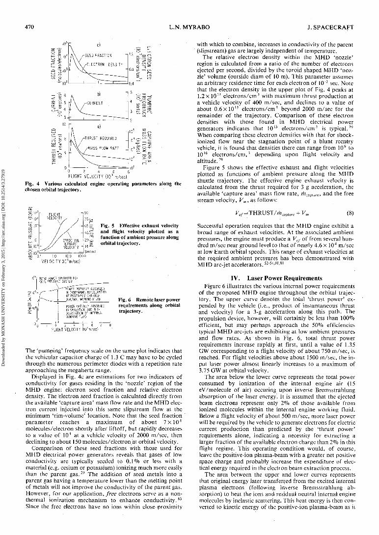
The total thrust required by the MHD vehicle for a 3-g ac-celeration and the available MHD engine 'capture area' massflow rate along the chosen orbital trajectory are shown in Fig.4a. Drag calculations for a 10 m diam sphere previously usedin the generation of Fig. 3b are also used here. Equation (4)may now be used to determine electrical current required bythe MHD engine as a direct function of thrust along thetrajectory. Again, the aerodynamic thrust component of Eq.(4) is ignored, since the predominant acceleration mechanismis expected to be due to self-magnetic field effects at thesehigh electric current levels. Reference to Fig. 4b, shows thatthe required electric current increases from about 360,000 Aat ground level to a peak at 600,000 A corresponding to themaximum required thrust for a vehicle velocity of 500 m/sec,and then reaches a low of about 280,000 A at orbital velocity.
Dow
nloa
ded
by M
ON
ASH
UN
IVE
RSI
TY
on
Febr
uary
3, 2
015
| http
://ar
c.ai
aa.o
rg |
DO
I: 1
0.25
14/3
.279
19
470 L.N. MYRABO J. SPACECRAFT
THRUST REQUIRED
/-MASS FLOW RATE
0 2 4 . 6FLIGHT VELOCITY (I03 m/sec)
Fig. 4 Various calculated engine operating parameters along thechosen orbital trajectory.
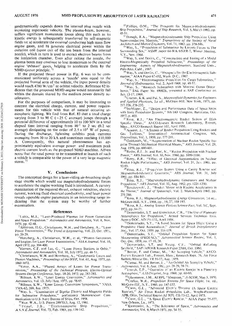
Fig. 5 Effective exhaust velocityand flight velocity plotted as afunction of ambient pressure alongorbital trajectory.
with which to combine, increases in conductivity of the parent(slipstream) gas are largely independent of temperature.
The relative electron density within the MHD 'nozzle'region is calculated from a ratio of the number of electronsejected per second, divided by the toroid shaped MHD 'noz-zle' volume (outside diam of 10 m). This parameter assumesan arbitrary residence time for each electron of 10"3 sec. Notethat the electron density in the upper plot of Fig. 4 peaks at1.2x 1013 electrons/cm3 with maximum thrust production ata vehicle velocity of 400 m/sec, and declines to a value ofabout 0.6xl013 electrons/cm3 beyond 2000 m/sec for theremainder of the trajectory. Comparison of these electrondensities with those found in MHD electrical powergenerators indicates that 1013 electrons/cm3 is typical.29
When comparing these electron densities with that for shock-ionized flow near the stagnation point of a blunt reentryvehicle, it is found that densities there can range from 109 to1016 electrons/cm,3 depending upon flight velocity andaltitude.79
Figure 5 shows the effective exhaust and flight velocitiesplotted as functions of ambient pressure along the MHDshuttle trajectory. The effective engine exhaust velocity iscalculated from the thrust required for 3 g acceleration, theavailable 'capture area' mass flow rate, mcap{urc, and the freestream velocity, FOO, as follows:
/- = THRUST//nca (8)
"O.I 1.0 10.0 100.0VELOCITY (I03m/sec)
Successful operation requires that the MHD engine exhibit abroad range of exhaust velocities. At the associated ambientpressures, the engine must produce a VeJ- of from several hun-dred m/sec near ground level to that of nearly 4.6 x 10⁴ m/secat low Earth orbital speeds. This range of exhaust velocities atthe required ambient pressures has been demonstrated withMHD arc-jet accelerators. 52-54'80'81
idV TOTAL POWER CONSUMED FOR100% EFFICIENT SYSTEM
of
POWER INITIALLY ABSORBEDIN GASDYNAMIC ACCELERATIONOF POSITIVELY CHARGEDINTERNAL WORKING FLUID
POWER INITIALLY ABSORBEDIN IONIZATION AND DIS-ASSOCIAT10N OF INTERNALWORKING FLUID
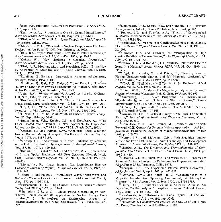
Fig. 6 Remote laser powerrequirements along orbitaltrajectory.
2 3 4 5 6 7FLIGHT VELOCITY (I03m/sec)
The 'pumping' frequency scale on the same plot indicates thatthe vehicular capacitor charge of 1.3 C may have to be cycledthrough the numerous perimeter diodes with a repetition rateapproaching the megahertz range.
Displayed in Fig. 4c are estimations for two indicators ofconductivity for gases residing in the 'nozzle' region of theMHD engine: electron seed fraction and relative electrondensity. The electron seed fraction is calculated directly fromthe available 'capture area' mass flow rate and the MHD elec-tron current injected into this same slipstream flow at theminimum 'rim-volume' location. Note that the seed fractionparameter reaches a maximum of about 7 x l 0 4
molecules/electron shortly after liftoff, but rapidly decreasesto a value of 103 at a vehicle velocity of 2000 m/sec, thendeclining to about 150 molecules/electron at orbital velocity.
Comparison of these seed fractions with those used forMHD electrical power generators reveals tfrat gases of lowconductivity are typically seeded to 0.1% or less with amaterial (e.g. cesium or potassium) ionizing much more easilythan the parent gas.29 The addition of seed metals into aparent gas having a temperature lower than the melting pointof metals will not improve the conductivity of the parent gas.However, for our application, free electrons serve as a non-thermal ionization mechanism to enhance conductivity.63
Since the free electrons have no ions within close proximity
IV. Laser Power RequirementsFigure 6 illustrates the various internal power requirements
of the proposed MHD engine throughout the orbital trajec-tory. The upper curve denotes the total 'thrust power' ex-pended by the vehicle (i.e., product of instantaneous thrustand velocity) for a 3-g acceleration along this path. Thepropulsion device, however, will certainly be less than 100%efficient, but may perhaps approach the 50% efficienciestypical MHD arc-jets are exhibiting at low ambient pressuresand flow rates. As shown in Fig. 6, total thrust powerrequirements increase rapidly at first, until a value of 1.35GW corresponding to a flight velocity of about 750 m/sec, isreached. For flight velocities above about 1500 m/sec, the in-put laser power almost linearly increases to a maximum of3.75 GW at orbital velocity.
The area below the lower curve represents the total powerconsumed by ionization of the internal engine air (15eV/molecule of air) occuring upon inverse Bremsstrahlungabsorption of the laser energy. It is assumed that the ejectedbeam electrons represent only 2% of those available fromionized molecules within the internal engine working fluid.Below a flight velocity of about 500 m/sec, more laser powerwill be required by the vehicle to generate electrons for electriccurrent production than predicted by the 'thrust power'requirements alone, indicating a necessity for extracting alarger fraction of the available electron charge than 2% in thisflight regime. This operating condition would, of course,leave the positive-ion plasma-beam with a greater net positivespace charge and probably increase the expenditure of elec-tical energy required in the electron beam extraction process.
The area between the upper and lower curves representsthat original energy later transferred from the excited internalplasma electrons (following inverse Bremsstrahlung ab-sorption) to heat the ions and residual neutral internal enginemolecules by inelastic scattering. This heat energy is then con-verted to kinetic energy of the positive-ion plasma-beam as it
Dow
nloa
ded
by M
ON
ASH
UN
IVE
RSI
TY
on
Febr
uary
3, 2
015
| http
://ar
c.ai
aa.o
rg |
DO
I: 1
0.25
14/3
.279
19
AUGUST 1976 MHD PROPULSION BY ABSORPTION OF LASER RADIATION 471
gasdynamically expands down the internal plug nozzle withincreasing supersonic velocity. The plasma-beam, however,suffers significant momentum losses along this path as itskinetic energy is subsequently transferred by self-magneticfields to: a) accelerate the external conducting high mass flowengine gases, and b) generate electrical power within theexitation coil (upon exit of the ion beam from the internalnozzle), which in turn is used to extract electron beams fromthe ionization chamber. Even after exiting the nozzle, theplasma beam may continue to lose momentum to the externalengine 'exhaust' gases, helping to accelerate them by theMHD ejector principle.71
If the projected thrust power in Fig. 6 was to be com-municated uniformly across a 'nozzle' area equal to theprojected frontal area of the vehicle, the input power densitywould reach 4780 W/cm2 at orbital velocity. Reference 82 in-dicates that the proposed MHD engine would necessarily fallwithin the domain shared by the medium power density ac-celerators.
For the purposes of comparison, it may be interesting tocontrast the electrical charge, current, and power require-ments for this vehicle with that of natural occuring at-mospheric lighting. We find from Ref. 83 that a total chargevarying from 3 to 90 C ( — 25 C average) jumps through apotential difference of approximately 10 to 100 MV in a totalelapsed time interval ranging from 10~2 to 2 sec (0.2 secaverage) dissipating on the order of 2.5 x 10⁹ W of power.During the discharge, lightning exhibits peak currentsaveraging from 10 to 20 kA and sometimes reaching 110,000A. Consequently, this natural phenomenon has ap-proximately equivalent average power and maximum peakelectric current levels as the proposed MHD machine. Alfvennotes that the total power to be transmitted at launch of sucha vehicle is comparable to the power of a very large magneticstorm.73
V. ConclusionsThe conceptual design for a laser-riding air-breathing single
stage shuttle which would use magnetohydrodynamic forcesto accelerate the engine working fluid is introduced. A cursoryexamination of the required thrust, exhaust velocities, electriccurrent, working fluid electrical conductivity, and laser powerreveals operable engine parameters in an interesting range in-dicating that the system may be worthy of furtherexamination.
References1 Lubin, M.J., "Laser-Produced Plasmas for Power Generation
and Space Propulsion," Astronautics and Aeronautics, Vol. 8, Nov.1970, pp. 42-48.
2Ahlstrom, H.G., Christiansen, W.H., and Hertzberg, A., "LaserPower Transmission," The Trend in Engineering, Vol. 23, Oct. 1971,pp. 20-29.
3Hertzberg, A., Christiansen, W.H., et al, "Photon Generatorsand Engines for Laser Power Transmission," AIAA Journal, Vol. 10,April 1972, pp. 394-400.
4Hansen, C.F. and Lee, G., "Laser Power Stations in Orbit,"Astronautics and Aeronautics, Vol. 10, July 1972, pp. 46-51.
5Christiansen, W.H. and Hertzberg, A., "Gasdynamic Lasers andPhoton Machines," Proceedings of the IEEE, Vol. 61, Aug. 1973, pp.1060-1072.
6Vetter, A.A., "Phased Arrays of Lasers for Power Trans-mission," Proceedings of the Technical Program, Electro-OpticalSystems Design Conference, Sept. 18-20, 1973, pp. 283-293.
7Billman, K.W., "Laser Energy Conversion," Astronautics andAeronautics, Vol. 13, July/Aug. 1975, pp. 56-65.
8Billman, K.W., "Laser Energy Conversion Symposium," NASATMX-62, 269, Jan. 1973.
9Way, S., "Examination of Bipolar Electric and Magnetic Fieldsfor Submarine Propulsion," preliminary Memorandum Com-munication to U.S. Navy Bureau of Ships, Oct. 1958.
10Rice, W.A., U.S. Patent 2997013, Aug. 12, 1961.n Fr i au f , J .B., "Electromagnetic Ship Propulsion,"
A.S.N.EJournal, Vol. 73, Feb. 1961, pp. 139-142.
12Phillips, O.M., "The Prospects for Magneto-HydrodynamicShip Propulsion," Journal of Ship Research, Vol. 5, March 1962, pp.43-51.
13D6ragh, R.A., "Magnetohydrodynamic Ship Propulsion UsingSuper-conducting Magnets," Transactions of the Society of NavalArchitects and Marine Engineers, Vol. 71, 1963, pp. 370-386.
14Way, S., "Propulsion of Submarines by Lorentz Forces in TheSurrounding Sea," ASME paper 64-WA/ENER-7, Winter Meeting,N.Y., Nov. 1964.
15 Way, S. and Devlin, C., "Construction and Testing of a ModelElectro-Magnetically Propelled Submarine," Proceedings of theEngineering Aspects of Magnetohydrodynamics, Stanford Univ.,Palo Alto, Calif., 1967.
16Way, S. and Devlin, C., "Prospects for the Electromagnetic Sub-marine," AIAA Paper 67-432, Wash. D.C., 1967.
17Way, S., "Electromagnetic Propulsion for Cargo Submarines,"Journal of Hydronautics, Vol. 2, April 1968, pp. 49-57.
18Way, S., "Research Submarines with Minimal Ocean Distur-bance," SAE Paper No. 690028, presented at SAE Conference onJan.13-17, 1969.
19Cramer, K.R. and Pai, S., Magnetofluid Dynamics for Engineersand Applied Physicists, 1st ed., McGraw-Hill, New York, 1973, pp.217-226,226-232. •
20Stuhlinger, E., "Design and Performance Data of Space Shipswith Ionic Propulsion Systems," 8th IAF Congress, Barcelona, Oct.1957, p. 403.
21 Rosa, R.J., "An Electromagnetic Rocket System of HighSpecific Thrust," AVCO-Everett Research Laboratory, Everett,Mass., AVCO Research Report 103, April 1958.
22 Ackeret, J., "A System of Rocket Propulsion Using Rockets andGas Turbines," International Astronautical Congress, 9th,Proceedings, Vol. 1, 1959, pp. 277-281.
23Goldsmith, M., "Augmentation of Nuclear Rocket Specific Im-pulse Through Mechanical-Electrical Means," ARS Journal, Vol. 29,Aug. 1959, pp. 600-601.
24Resler, E.L. Jr. and Rott, N., "Rocket Propulsion with NuclearPower," ARS Journal, Vol. 30, Nov. 1960, pp. 1099-1100.
25 Berry, E.R., "Effect of Electrical Augmentation on NuclearRocket Flight Performance," ARS Journal, Vol. 31, Jan. 1961, pp.92-93.
26Rosa, R.J., "Propulsion System Using a Cavity Reactor andMagnetohydrodynamic Generator," ARS Journal, Vol. 31, July1961, pp. 884-885.
27Rosa, R.J., "Magnetohydrodynamic Generators and NuclearPropulsion," ARS Journal, Vol. 32, Aug. 1962, pp. 1221-1230.
28Rosciszewski, J., "Rocket Motor with Electric Acceleration inthe Throat," Journal of Spacecraft, Vol. 2, March-April 1965, pp.278-280.
29Rosa, R.J., Magnetohydrodynamic Energy Conversion, 1st ed.,McGraw-Hill, N.Y., 1968, pp., 19,27, 189-193.
30Rosa, R.J., Analog Science Fiction/Science Fact, Vol. XC, Sept.1972, pp. 64-71.
31 Demetriades, S.T. and Kretschmer, C.B., "The Use of PlanetaryAtmospheres for Propulsion," Armed Services Technical Info.Agency DOC, AD 154-132, April 1958.
32Demetriades, S.T., "A Novel System for Space Flight Using aPropulsive Fluid Accumulator," Journal of British InterplanetarySoc., Vol. 17, Oct. 1959, pp. 114-119.
33 Demetriades, S.T., "Orbital Propulsion System for SpaceManeuvering (PROFAC)," Astronautical Science Review, Vol. 1,Oct.-Dec. 1959, pp. 17-18,26.
34 Demetriades, S.T. and Young, C.F., "Orbital RefuelingSatelloid," SAE/AFOSR Research Paper 230H, Oct. 1960.
35Berner, F. and Camac, M., "Air Scooping Vehicle," AVCO-Everett Research Lab., Everett, Mass., Research Rept. 76, Air ForceBallistic Missile Div. TR 59-17, Aug. 1959.
36Camac, M. and Berner, F., "An Orbital Air Scooping Vehicle,"Astronautics, Vol. 6, Aug. 1961, pp. 28-29, 70-71.
37French, E.P., "Operation of an Electric Ramjet in a PlanetaryAtmosphere," AAS Preprint, Aug. 1960, pp. 60-90.
38Glassmeyer, J.M., AFRPL "Ideagram,'M-SCO#, May 3, 1970.39Corliss, W.R., Propulsion Systems for Space Flight, 1st. ed.,
McGraw-Hill, N.Y., 1960, pp. 147-152.40Cann, G.L., "Advanced Electric Thruster (A Space Electric
Ramjet)," Air Force Rocket Propulsion Lab., Wright-PattersonAFB, Ohio, Technical Report AF RPL-TR-73-12, April 1973.
41Cann, G.L., "A Space Electric Ramjet," AIAA Paper 75-377,New Orleans, La., 1975.
42Kantrowitz, A., "The Relevance of Space," Astronautics andAeronautics, Vol. 9, March 1971, pp. 34-35.
Dow
nloa
ded
by M
ON
ASH
UN
IVE
RSI
TY
on
Febr
uary
3, 2
015
| http
://ar
c.ai
aa.o
rg |
DO
I: 1
0.25
14/3
.279
19
472 L.N. MYRABO J. SPACECRAFT
43Rom, F.E. and Putre, H.A., "Laser Propulsion," NASA TM-X-2510, April 1972.
44Kantrowitz, A., "Propulsion to Orbit by Ground-Based Lasers,"Astronautics and Aeronautics, Vol. 10, May 1972, pp. 74-76.
45Pirri, A..N. and Weiss, R.F., "Laser Propulsion AIAA Paper 72-719, Boston, Mass., 1972.
46Minovitch, M.A., "Reactorless Nuclear Propulsion-The LaserRocket," AIAA Paper 72-1095, New Orleans, La. 1972.
47Baty, R.S., "Space Propulsion -Let's Do It Better Electrically,"Air University Review, Vol. 25, Nov.-Dec. 1973, pp. 10-15.
48Cohen, W., "New Horizons in Chemical Propulsion,"Astronautics and A eronautics, Vol .11, Dec. 1973, pp• 46-51.
49Pirri, A.N., Monsler, M.J., and Nebolsine, P.E., "Propulsionby Absorption of Laser Radiation," AIAA Journal, Vol. 12, Sept.1974, pp. 1254-1261.
50Stuhlinger, E., Berlin. 5th International Astronautical Congress,Springer, Vienna, 1954, p. 100.
51 Stuhlinger, E., Hale, D.P., Daley, C.C., and Katz, L., "The Ver-satility of Electrically Powered Spacecraft for Planetary Missions,"AIAA Paper 69-253, Williamsburg, Va., 1969.
52Jahn, R.G., Physics of Electric Propulsion, 1st ed., McGraw-Hill, N.Y., 1968, pp. 235, 253, 236, 260, 115.
53 Bruckner, A.P. and Jahn, R.G., "Exhaust Plume Structure in aQuasi-Steady MPD Accelerator, "Vol. 12, Sept. 1974, pp. 1198-1203.
54Hii'gel, H., "Flow Rate Limitations in the Self-Field Ac-celerator, "AIAA Journal, Vol. 12, Nov. 1974, pp. 1461-1462.
55O'Neill, G.K., "The Colonization of Space," Physics Today,Vol. 27, Sept. 1974, pp. 32-40.
56Buonadonna, V.R., Knight, C.J., and Hertzberg, A., "TheLaser Heated Wind Tunnel-A New Approach to HypersonicLaboratory Simulation," AIAA Paper 73-211, Wash. D.C., 1973.
57Stallcop, J.R. and Billman, K.W., "Analytical Formula for theInverse Bremsstrahlung Absorption Coefficient," Plasma Physics,Vol 16, 1974, pp. 1187-1189.
58Stallcop, J.R., "Absorption of Infrared Radiation by Electronsin the Field of a Neutral Hydrogen Atom," Astrophysical Journal,Vol. 187, Jan. 1974, p. 179-183.
59Bunkin, F.B., Kazakov, A.E., and Fedorov, M.V., "Interactionof Intense Optical Radiation with Free Electrons (NonrelativisticCase)," Soviet Physics Uspekhi, Vol. 15, No. 4, Jan.-Feb. 1973, pp.416-435.
60Mongolfier, P., "Laser Induced Gas Breakdown: ElectronCascade," Journal of Physics, D: Applied Physics, Vol. 5, 1972, pp.1438-1447.
61 Vegrie, P. and Floux, F., "Breakdown Wave, Shock Wave, andRadiation Wave in Laser Created Plasmas," AIAA Journal, Vol. 8,Aug. 1970, pp. 1405-1411.
62Fleischmann, H.H., "High-Current Electron Beams," PhysicsToday, Vol. 28,May 1975, pp. 35-43.
63Sternglass, E.J., et al., "MHD Power Generation by Non-Thermal lonization and its Application to Nuclear Energy Con-version," 3rd Symposium on Engineering Aspects ofMagnetohydrodynamics, Gordon and Breach, N.Y., 1964, pp. 205-222.
64Dommasch, D.O., Sherby, S.S., and Connolly, T.F., AirplaneAerodynamics, 3rd ed., Pitman Publishers, N.Y., 1961, p. 192.
65Poukey, J.W. and Toepfer, A.J., "Theory of SuperpinchedRelativistic Electron Beams," The Physics of Fluids, Vol. 17, Aug.1971, pp. 1582-1591.
66Yoshikawa, S., "Force-Free Configuration of a High-IntensityElectron Beam," Physical Review Letters, Vol. 26, Feb. 8, 1971, pp.295-297.
67Hammer, D.A. and Rostoker, N., "Propagation of HighCurrent Relativistic Electron Beams," The Physics of Fluids, Vol. 13,July 1970, pp. 1831-1850. '
68Ivanov, A.A. and Rudakov, L.I., "Intense Relativistic ElectronBeam in a Plasma," Soviet Physics JETP, Vol. 31, Oct. 1970, pp.715-719.
69Hiigel, H., Kruelle, G., and Peters, T., "Investigations onPlasma Thrusters with Thermal and Self Magnetic Acceleration,"AIAA Journal, Vol. 5, March 1967, pp. 551-558.
70Hugel, H. "Self Magnetic Effect in Arcjet Engines," AIAAJournal, Vol. 6, Aug. 1968, pp. 1573-1574.
71Heiser, W.H., "Analysis of a Magnetohydrodynamic Ejector,"Journal of Applied Mechanics, Vol. 32, Sept. 1965, pp. 680-683.
72Winterberg, F., "Rocket Propulsion by ThermonuclearMicrobombs Ignited with Relativistic Electron Beams," Raum-fahrtforschung, Vol. 15, Sept.-Oct., 1971, pp. 208-217.
73Alfven, H., "Spacecraft Propulsion: New Methods," Science,Vol. 176, April 1972, pp. 167-168.
74 Way mouth, J.F., "Electrical Energy from High TemperaturePlasma," Journal of the Institute of Electrical Engineers, Vol. 8,Aug. 1962, p. 380.
75Donaldson, C. duP. and Brunner, M.J., "Discussion of a Self-Powered MHD Control for Re-entry Vehicle Application," 3rd Sym-posium on Engineering Aspects of Magnetohydrodynamics, March1962, pp. 559-577.
76Henry, J.R. and McLellan, C.H., "Air-Breathing LaunchVehicle for Earth-Orbit Shuttle-New Technology and DevelopmentApproach," Journal of Aircraft, Vol. 8, May 1971, pp. 381-387.
77Shapiro, A.H., The Dynamics and Thermodynamics of Com-pressible Fluid Flow, Vol. 1, 1st ed. Ronald Press., N.Y., 1953, pp.190-218,410.
78Edwards, C.L. W., Small, W.J., and Weidner, J.P., "Studies ofScramjet/Air frame Integration Techniques for Hypersonic Aircraft,"AIAA Paper 75-58, Pasadena, Calif., 1975.
79Touryan, K.J., "A Hypersonic Plasma Power Converter,"AIAA Journal, Vol. 3, April 1965, pp. 652-659.
80Garrison, G.W., and Smith, R.T., "Characteristics of aMagnetic Annular Arc Operating Continuously at AtmosphericPressure, "AIAA Journal, Vol. 8, Sept. 1970, pp. 1714-1715.
81 Harry, J.E., "Characteristics of a Magnetic Annular ArcOperating Continuously at Atmospheric Pressure," AIAA Journal,Vol. 9, Aug. 1971, pp. 1660-1661.
82Kantrowitz, A., "Horizons in Plasma Physics," Astronauticsand Aeronautics, Vol. 3, Jan. 1965, pp. 52-65.
^Handbook of Chemistry and Physics, 54th ed., Chemical RubberCo. Press, Cleveland, Ohio 1973-1974, p. F-193.
Dow
nloa
ded
by M
ON
ASH
UN
IVE
RSI
TY
on
Febr
uary
3, 2
015
| http
://ar
c.ai
aa.o
rg |
DO
I: 1
0.25
14/3
.279
19


![EXACT SOLUTION OF MAGNETO-HYDRODYNAMIC SYSTEM … · metals, MHD power generation and propulsion [14, 15]. Despite its apparent simplicity, MHD describes a remarkably rich and varied](https://img.dokumen.tips/doc/110x75/5f0316207e708231d407778d/exact-solution-of-magneto-hydrodynamic-system-metals-mhd-power-generation-and-propulsion.jpg)


![CHAP04. PLASMA DISPLAY PANEL - …121C771E4C273B84482… · PLASMA DISPLAY PANEL ... ¾역학적: 전자기력의발생[MHD 발전, plasma propulsion] ¾화학적: ... PDP의효율의개선방향](https://img.dokumen.tips/doc/110x75/5b8e444b09d3f2a0138d3e3c/chap04-plasma-display-panel-121c771e4c273b84482-plasma-display-panel-.jpg)