Embed Size (px)
Citation preview

Machine Tool's Total Solution공작기계 주변기기 | 삼천리기계 종합 카달로그 Vol.11Samchully General Catalog Korean + English ver.

Machine Tool's Total Solution
공작기계 주변기기 | 삼천리 종합 카달로그 Vol.11
Samchully General Catalog Korean + English ver.

Contents
파워척 4
로터리 실린더 70
스크롤척 104
바이스 122
마그네트척 146
드릴링 탭핑머신 158
면취기 164
기타 악세사리 168
POWER CHUCK
ROTARY CYLINDER
SCROLL CHUCK
VISE
MAGNET CHUCK
DRILLING & TAPPING MACHINE
CHAMFER MACHINE
ACCESSORIES

POWER CHUCK
삼천리기계는 터닝센터 그리고 머시닝센터에서의 다양하고 광범위한
머신툴 토탈 솔루션을 제공하는 글로벌 기업입니다.
제조산업의 생산성 향상과 고정밀 가공을 위한 끊임없는 신제품 개발과 기술혁신이야 말로
삼천리기계가 지향하는 미래 가치입니다.
Samchully is the global machine tool's total company which has been supplied various
and wide range of solutions for turning and machining center.we are aiming for the
improvement of productivity and high precision machining to manufacturing industry
through awesome products and technology innovation.

IDFSelf centering 2+2 JawPower Chuck
6P
HSStandard 3-jaw HighSpeed Open-Center Chuck
24P
HS-A(Adaptor)
(Long Stroke)
HST/F
HSL
MH
MHT/F
HCH
HCH-A
Standard 3-jaw High-Speed Open-Center Chuck
2, 4-jaw High-Speed Open-Center Chuck
3-jaw High-Speed Open-Center Chuck
Mega-Bore 2, 4-jaw High-Speed Open-CenterChuck
Standard Mega-Bore 3-jaw High-Speed Open-Center Chuck
Standard 3-jaw Open- Center Chuck
Standard 3-jaw Open-Center Chuck
26P
30P
32P
34P
36P
38P
42P
(Adaptor)
HCHT/F2, 4-jaw Open-Center Chuck
46P
HC
HC-A
HCT/F
HC-SE
HCL
HCLT/F
HCWF
Standard 3-jaw Close- Center Chuck
Standard 3-jaw Close- Center Chuck
2, 4-jaw Close-Center Chuck
3-jaw Sealed Close-Center Chuck
Standard 3-jaw Close- Center Chuck
2, 4-jaw Close-Center Chuck
4-jaw Double Wedge Hydraulic Chuck
48P
54P
58P
62P
64P
66P
68P
(Adaptor)
(Long Stroke)
(Long Stroke)
IDSSelf centering 2+2+2 JawPower Chuck
10P
UR
QJC
PAC
RTC
MCA
MCH
Standard Mega Bore High-Speed Open-Center Chuck
Quick Jaw Change Chuck
Mega-Bore Pneumatic Self-Contained Chuck
Rotary Table Chuck
Stationary Pneumatic Chuck
Stationary Hydraulic Chuck
12P
14P
16P
18P
20P
22P

SAMCHULLYPOWER Chuck 006
IDF / Self centering 2+2 Jaw Power Chuck
01Cost-saving compatibility with standard cyilnders

SAMCHULLYPOWER Chuck 007
Pow
er C
huck
02Better performance than standard 3-jaw
Easy to measure the work-piece after self-cutting
Use irregular work-piece without interchanging chuck
03
04

SAMCHULLYPOWER Chuck 008
Power C
huck
IDF Self centering 2+2 Jaw Power Chuck
Application / Customer's Benefit
High precision self-centering 4-Jaw power chuck(2+2 Jaw)
Technical features
Ideal for rectangular and square work pieces ; self-centering in two axles
Single wedge actuation does not require dual-piston cylinder
2+2 Jaw chuck with 2 independent self-centering jaws
SPECIFICATIONS
IDF-210 IDF-260 IDF-310 IDF-380
Jaw Stroke Radial. 5.2 6.2 6.2 6.2
Compensation ± 2 ± 2 ± 2 ± 2
Plunger Stroke 10 12 12 12
Max. Permissible Input Force 40(4081) 50(5102) 70(7143) 80(8163)
Max. Static Gripping Force 100(10204) 130(13265) 180(18367) 220(22448)
Max. r.p.m. 4000 3200 3000 2100
Operating Cylinder Y-1225RE Y-1530RE Y-1530RE Y-2035RE
Weight 24 43 68 110
Moment of inertia 0.14 0.39 0.88 2.2
Maximum turning speed is based upon actual measurment.
Specifications are subject to change without notice.
When using taller heavier jaw or clamping on a bigger diameter reduce draw pull rotating speed accordingly.
ACTUAL GRIPPING FORCE DIAGRAM

SAMCHULLYPOWER Chuck 009
Pow
er C
huck
DIMENSIONS
It is recommended to grease chucks at least twice a day in order to maximize longevity.
IDF-210 IDF-260 IDF-310 IDF-380
ΦA 210 260 310 380
B 100 120 127 135
ΦC 170 220 220 300
ΦD 133.4 171.4 171.4 235
E 5 5 5 5
F 24 30 30 40
G M12 M16 M16 M20
H 25 30 30 43
J (Max/Min) 39/10 45/13 58/13 53/18
K (Max/Min) 34.2/29 46.2/40 53.2/47 74.2/68
L 35 40 50 62
M 14 16 18 25.5
N 5 5 5 5
O 3 3 3 3
P(Max/Min) 52/62 53/65 53/65 93/81
Q 29 33 33 33
R 42 50 55 55
S M16x80 M20x80 M20x80 M30x125
T 95 98 115 135
U 42 46 54 64
V M12x30 M12x35 M14x45 M20x45
RELATED PRODUCT
94p
Cylinder

SAMCHULLYPOWER Chuck 010
Power C
huck
IDS Self centering 2+2+2 Jaw Power Chuck
Application / Customer's Benefit
High accuracy Self centering 2+2+2 jaw power chuck
Technical features
Ideal for thin workpiece (Easily deformable workpiece)
Compensating deviation of workpieces by 2+2+2 jaw (clamping 6 point at once)
100% compatibility with existing cylinder
SPECIFICATIONS
IDS-250 IDS-315
Jaw Stroke Radial. 6 6
Compensation 4 4
Plunger Stroke 12 12
Max. Permissi ble Input Force 38 40
Max. Gripping Force 64 80
Max. r.p.m. 3000 2500
Operating Cylinder Y-1530RE Y-1530RE
Weight 39 65
Moment of inertia 0.35 0.75
Maximum turning speed is based upon actual measurment.
Specifications are subject to change without notice.
When using taller heavier jaw or clamping on a bigger diameter reduce draw pull rotating speed accordingly.
ACTUAL GRIPPING FORCE DIAGRAM

SAMCHULLYPOWER Chuck 011
Pow
er C
huck
DIMENSIONS
It is recommended to grease chucks at least twice a day in order to maximize longevity.
IDS-250 IDS-315
ΦA 250 315
B 113 212
ΦC 220 220
ΦD 171.4 171.4
E 6 6
F 34 38
G M16 M16
H 20 20
J (Max/Min) 42/11 64/11
K (Max/Min) 57/51 68/62
L 31 31
M 12 12
N 4 4
O 3 3
P(Max/Min) 63/75 63/75
Q 36 36
R 56 70
S M20x90 M20x90
T 72 72
U 35 35
V M10x30 M10x30
RELATED PRODUCT
94p
Cylinder

SAMCHULLYPOWER Chuck 012
Power C
huck
UR Standard Mega Bore 3-Jaw High-Speed Open-Center Chuck
UR-175 UR-210 UR-250 UR-315
Thru Hole Dia. 56 66 82 122
Grip Dia. Max. 175 210 254 315
Grip Dia. Min. 16 23 30 74
Jaw Stroke Dia. 6.4 8.0 10.0 10.6
Plunger Stroke 14 17.5 22 23
Max. Permissible Input Force 25(2551) 38(3878) 50(5102) 50(5102)
Max. Static Gripping Force 70(7143) 108(11020) 145(14796) 145(14796)
Max. r.p.m. 6000 5000 4000 3200
Weight 11 19.5 30 42
Moment of inertia 0.05 0.12 0.27 0.62
Operating Cylinder SD-15452 SD-17568 SD-18582 SD-30516
Max. Hydraulic Pressure 1.8(18.35) 2.5(25.49) 2.8(28.55) 1.4(14.27)
ACTUAL GRIPPING FORCE DIAGRAM
SPECIFICATIONS
Maximum turning speed is based upon actual measurment.
Specifications are subject to change without notice.
Application / Customer's Benefit
Mega-bore 3-jaw wedge-style, open-center power chuck
Technical features
Case hardened body to assure greatest precision and long life
Easy to attach locator
When using taller heavier jaw or clamping on a bigger diameter reduce draw pull rotating speed accordingly.

SAMCHULLYPOWER Chuck 013
Pow
er C
huck
DIMENSIONS
Ă
It is recommended to grease chucks at least twice a day in order to maximize longevity.
UR-175 UR-210 UR-250 UR-315
ΦA 175 210 254 315
B 81 92 103 115
ΦC 160 170 220 300
ΦD 133.4 133.4 171.4 235
E 5 5 5 5
F 56 66 82 122
G 14 17.5 22 23
H (max./min.) 4 / -10 7 / -10.5 13 / -9 19 / -4
I 18 20 20 23
J (UR-D/UR-M) M10 / M10 M12 / M12 M12 / M12 M16 / M16
K (max) M62x1.5P M72x1.5P M85x2.0P M125x2.0P
L M12 M12 M16 M20
M 70 95 110 125
N (UR-D/UR-M) 16.5 / 20 23 / 25 30 / 30 30 / 30
O (max./min.) 22 / 10 23 / 11 32 / 14 37 / 15
P (max./min.) 38/35 47/43 57/62 81/76
Q 31 35 40 50
R 71 78 92 143
a (UR-D/UR-M) 1/16"x90° / 1.5x60° 1/16"x90° / 1.5x60° 1/16"x90° / 1.5x60° 1/16"x90° / 1.5x60°
b 33 38 45 45
d (UR-D/UR-M) 12 / 14 17 / 14 21 / 16 21 / 21
e 3 3 4 4
f 2.5 2.5 3.5 3.5
g 16 16 16 20
h 36 45 60 60
m 65 80 102 100
n 5 5 5 5
r M8 M8 M10 M10
RELATED PRODUCT
176p 170p 72p
Adaptor H/S Jaw Cylinder
Blank and machined draw-nuts are available. ‘K’ is Max. Draw nut size.

SAMCHULLYPOWER Chuck 014
Power C
huck
QJC Quick Jaw Change Chuck
Application / Customer's Benefit
Minimal jaw set-up times(within 1 minute), Jaws are reversible(180º)
High repeatability when changing jaws(runout <0.02mm)
Technical features
Minimum loss of gripping force because of wedge bars
The built-in safety interlock eliminates misoperation
ACTUAL GRIPPING FORCE DIAGRAM
SPECIFICATIONS
QJC-206 QJC-208 QJC-210 QJC-212 QJC-215 QJC-220
Jaw Stroke Dia. 11.4 14.4 16 16 17 20
Plunger Stroke 20 25 28 28 32 42
Pemissible Input Force 30(3059) 54(5404) 65(6628) 90(9177) 133(13562) 120(12236)
Max.static Gripping Force 45(4538) 100(10197) 115(11726) 160(16315) 240(24473) 250(25492)
Max. r.p.m. 6000 5500 4000 3600 3500 2200
Weight 13 24 42 66 109 225
Moment of inertia 0.11 0.11 0.41 0.97 2.3 6.5
Operating Cylinder SD-13546 SD-17568 SD-18582 SD-21511 SDL-25411 SDL-30516
Max. Hydraulic Pressure 3.0(30.5) 3.0(35.6) 3.7(37.7) 4.0(40.7) 4.0(40.7) 2.9(29.5)
When using taller heavier jaw or clamping on a bigger diameter reduce draw pull rotating speed accordingly.

SAMCHULLYPOWER Chuck 015
Pow
er C
huck
RELATED PRODUCT
176p 172p 72p
Adaptor H/S Jaw Cylinder
Blank and machined draw-nuts are available. ‘K’ is Max. Draw nut size.
DIMENSIONS
It is recommended to grease chucks at least twice a day in order to maximize longevity.
QJC-206 QJC-208 QJC-210 QJC-212 QJC-215 QJC-220
ΦA 165 215 260 315 400 500
B 95 111 129.3 138.1 144 182
ΦC 140 170 220 220 300 380
E 14 18 23.7 24.9 25 34
ΦF 45 66 81 104 128 155
G max. 20.2 25 28 28.5 32 42
G min. 0 0 0 0 0 0
H 15 17.5 22 23.2 22 29
ΦJ 68 95 114 148 180 207
K1 M50 M75 M90 M115 M138 M165
K2 M60 M87 M105 M135 M160 M185
L1 3-M10 3-M12 3-M16 3-M16 3-M20 3-M24
L2 3-M12 3-M16 3-M12 3-M20 3-M24 3-M20
ι1 80° 80° 80° 80° 70° 85°
ι2 20° 65° 65° 70° 60° 75°
M 104.8 133.35 171.4 171.4 235 330.2
N 85 97 125 125 145 160
P 32 40 40 40 54 60
Q max. 76.8 118.3 129.7 159.1 182.4 225
Q min. 58 71.2 102.2 106.9 121.9 141
T1 20 22 30 30 35 45
T2 20 22 26 32 32 48
U 8 10 12 12 12 18
V 2.5 2.5 3 3 3 4
W 8 10 10 10 10 12
SAMCHULLYPOWER Chuck 016
Power C
huck
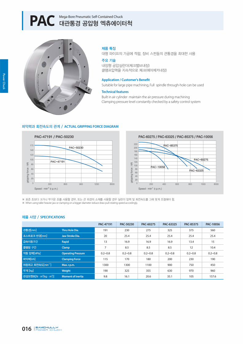
PAC Mega-Bore Pneumatic Self-Contained Chuck
ACTUAL GRIPPING FORCE DIAGRAM
SPECIFICATIONS
PAC-47191 PAC-50230 PAC-60275 PAC-63325 PAC-85375 PAC-10056
Thru Hole Dia. 191 230 275 325 375 560
Jaw Stroke Dia. 20 25.4 25.4 25.4 25.4 25.4
Rapid 13 16.9 16.9 16.9 13.4 15
Clamp 7 8.5 8.5 8.5 12 10.4
Operating Pressure 0.2~0.8 0.2~0.8 0.2~0.8 0.2~0.8 0.2~0.8 0.2~0.8
Clamping Force 115 170 180 200 230 190
Max. r.p.m. 1300 1300 1100 900 750 450
Weight 190 325 355 630 970 960
Moment of inertia 9.8 16.1 20.6 35.1 105 157.6
Application / Customer's Benefit
Suitable for large pipe machining, Full spindle through-hole can be used
Technical features
Built in air cylinder maintain the air pressure during machining
Clamping pressure level constantly checked by a safety control system
When using taller heavier jaw or clamping on a bigger diameter reduce draw pull rotating speed accordingly.

SAMCHULLYPOWER Chuck 017
Pow
er C
huck
DIMENSIONS
It is recommended to grease chucks at least twice a day in order to maximize longevity.
PAC-47191 PAC-50230 PAC-60275 PAC-63325 PAC-85375 PAC-10056
ΦA 470 570 605 685 850 1000
B 238 280 280 305.5 352 330
C 240 282 284 329.5 356 334
ΦD 448 550 585 666 830 910
E 26 26 26 33 33 33
F 17 17 17 19 19.5 19.5
J 8 8 8 8 8 10
ΦK 400 500 535 610 775 850
ΦL 310 415 450 510 700 700
ΦM 374 474 508 580 745 815
ΦN 470 570 605 685 850 1000
ΦO 191 230 275 325 375 560
P Max. 147 180.5 205.9 230.9 268 346.3
P Min. 127 156 180.5 205.5 268 321.1
Q 170 195 195 240 300 300
R 25 37 37 42 68 68
S 40 40 40 65 65 65
T 60 60 60 75 75 75
U 25.5 25.5 25.5 30 30 30
V 60 80 78 80 90 88
W 9-M12 12-M12 12-M12 12-M16 12-M16 12-M16
X 40˚ 30˚ 30˚ 30˚ 30˚ 30˚

SAMCHULLYPOWER Chuck 018
Power C
huck
RTC Rotary Table Chuck
SPECIFICATIONS
RTC-110 RTC-160 RTC-210 RTC-260
Thru Hole Dia. 8 20 30 43
Jaw Stroke Dia. 5.2 5.2 6.3 6.3
Plunger Stroke 11.3 11.5 13.7 13.6
Max. Static Gripping Force 7.5 21 33 48
Max. Pneumatic Pressure 0.7 (7) 0.7 (7) 0.7 (7) 0.7 (7)
Max. r.p.m. 100 72 50 50
Weight (included Soft Jaws) 7.3 22 27.7 42.5
Application / Customer's Benefit
Suitable for indexing machining, Power chuck jaws can be compatible
It is ideal for RTC chuck to be operating in SPM (Special Purpose Machine) by built-in
cylinder system. RTC chuck isn't needful for cylinder system.
Technical features
Sealed aginst coolant and chips
With built-in cyliner, less space and easy operation

SAMCHULLYPOWER Chuck 019
Pow
er C
huck
DIMENSIONS
It is recommended to grease chucks at least twice a day in order to maximize longevity.
RTC-110 RTC-160 RTC-210 RTC-260
Φ A 145 210 260 304
B 92 102 117 125
Φ C 113 166 216 264
Φ D 80 80 110 140
E 98 148 195 234
F 6 7 8 8
Φ G 8 20 30 43
Φ H 124 175 230 268
J 27 36 42 46
K 14 20 25 30
L max. 32.8 41.9 53 66
L min. 30.2 39.3 49.85 62.85
M max. 5.4 9.25 14.75 16
M min. 2.4 4.75 8.75 8.5
N 55 72 95 110
O 11 15 17 16
P 25.5 31 32 39.5
Q 12.2 18 20 21
R 25.5 32.3 31.5 39.5
S 12.2 15.2 21 21
T M6x95L M8x105L M8x125L M10x130L
U 23 31 35 40

SAMCHULLYPOWER Chuck 020
Power C
huck
MCA Stationary Pneumatic Chuck
SPECIFICATIONS
MCA-04 MCA-06 MCA-08 MCA-10
Clamping Force (Pneumatic 6bar) 7.5(765) 21(2140) 33(3300) 48(4800)
Jaw Stroke Dia. 5.2 5.2 6.3 6.3
Grip Dia. Max 110 165 210 254
Grip Dia. Min 10 23 30 50
Max. Pneumatic Pressure 0.7(7) 0.7(7) 0.7(7) 0.7(7)
Weight 7.3 16 28 43
Application / Customer's Benefit
Suitable for machining center, Minimun installation space
Higher machining efficiency
Technical features
Sealed aginst coolant and chips
With built-in air cyliner, less space and easy operation

SAMCHULLYPOWER Chuck 021
Pow
er C
huck
DIMENSIONS
It is recommended to grease chucks at least twice a day in order to maximize longevity.
MCA-04 MCA-06 MCA-08 MCA-10
ΦA 148 203 248 300
ΦB 110 165 210 254
ΦC 20 25 36 50
ΦD - 20 30 43
E 90 95 106 110
F 15 15 15 16
G 75.5 103 125.5 147.5
H 27 36 42 46
J 55 72 95 110
K 23 31 35 40
N M8 M8 M8 M10
ΦL(P.C.D) 130 185 230 280
P - 55 68 80
Q - 58 68 80
ΦR 9 11 11 13
T M10 M10 M10 M12

SAMCHULLYPOWER Chuck 022
Power C
huck
MCH Stationary Power Chuck
SPECIFICATIONS
Application / Customer's Benefit
Suitable for machining center, Minimun installation space
Higher machining efficiency
Technical features
Sealed aginst coolant and chips
With built-in HYD. Cylinder, less space and easy operation
MCH-06 MCH-08 MCH-10
Clamping Force (25bar) 55 85 125
Jaw Stroke Dia. 5.2 6.3 6.8
Grip Dia. Max 169 210 254
Grip Dia. Min 15 30 50
Max. Pneumatic Pressure 3(30.5) 3(30.5) 3(30.5)
Weight 18 30 44

SAMCHULLYPOWER Chuck 023
Pow
er C
huck
It is recommended to grease chucks at least twice a day in order to maximize longevity.
DIMENSIONS
MCH-06 MCH-08 MCH-10
ΦA 210 255 300
ΦB 165 210 254
ΦC 25 36 50
ΦD 20 30 43
E 100 111 121
F 20 20 20
G 103 125.5 147.5
H 36 42 46
J 72 95 110
K 31 35 40
N M8 M8 M10
ΦL (P.C.D.) 185 235 280
P 55 68 80
Q 18 25 35
ΦR 11 11 13
T M10 M10 M12
Order production: MCH -08, MCH-10

SAMCHULLYPOWER Chuck 024
Power C
huck
HS Standard 3-Jaw High-Speed Open-Center Chuck
ACTUAL GRIPPING FORCE DIAGRAM
SPECIFICATIONS
Maximum turning speed is based upon actual measurment.
Specifications are subject to change without notice.
Samcully Machinery Co., Ltd. is no longer an OEM manufacturer for Kitagawa® Iron Works Co., Ltd.
HS-05 HS-06 HS-08 HS-10 HS-12
Thru Hole Dia. 33 46 52 77 91
Grip Dia. Max 135 169 210 254 304
Grip Dia. Min 12 15 13 31 34
Jaw Stroke Dia. 5.4 5.5 7.4 8.8 10.6
Plunger Stroke 10 12 16 19 23
Permissible Input Force 17.5(1784) 22(2243) 34.8(3549) 43(4385) 55(5608)
Max. Static Gripping Force 36(3671) 57(5812) 86(8769) 111(11319) 144(14686)
Max. r.p.m. 7000 6000 5000 4200 3300
Weight 6.7 11.9 22.3 34.5 55.3
Moment of inertia 0.018 0.058 0.17 0.315 0.738
Operating Cylinder SH-10036 SH-13046 (SYH-1246) SH-15052 (SYH-1552) SH-18077 (SYH-1877) SYH2091
Max. Hydraulic Pressure 2.9(30) 2.8(28.6) 2.65(27) 2.7(27.5) 2.7(27.5)
Operating Hard Jaw HB04N1 HB06A1 HB08A1 HB10A1 HB12N1
KITAGAWA® Model B-205 B-206 B-208 B-210 B-212
Application / Customer's Benefit
Standard high-speed 3-jaw wedge-style opencenter power chuck
Technical features
Gripping force transmisstion by wedge structure
Hardening treatment to assure greatest precision and longer chuck life
When using taller heavier jaw or clamping on a bigger diameter reduce draw pull rotating speed accordingly.

SAMCHULLYPOWER Chuck 025
Pow
er C
huck
RELATED PRODUCT
176p 170p 78p
Adaptor H/S Jaw Cylinder
Blank and machined draw-nuts are available. ‘K’ is Max. Draw nut size.
DIMENSIONS
It is recommended to grease chucks at least twice a day in order to maximize longevity.
HS-05 HS-06 HS-08 HS-10 HS-12
ΦA 135 169 210 254 304
B 60 81 91 100 110
ΦC(H6) 110 140 170 220 220
ΦD 82.6 104.8 133.4 171.4 171.4
E 4 5 5 5 6
ΦF 33 46 52 77 91
G max. 1 11 14.5 8.5 8
G min. -9 -1 -1.5 -10.5 -15
H 20 19 20.5 25 28
ΦJ 12 20 30 45 50
K max. M42x1.5 M55x2.0 M60x2.0 M85x2.0 M100x2.0
L 3-M10x60 6-M10x95 6-M12x105 6-M16x120 6-M16x130
M 26 29 39 43 50.5
N 54 72 95 110 111
P 14 20 25 30 30
Q max. 26.5 32 38.7 51 61.3
Q min. 23.8 29.25 35 46.6 56
R max. 19.75 22.75 29.75 33.75 45.75
R min. 7.75 9.25 14.75 14.25 15.75
T 23 31 35 40 49
U 10 12 14 16 21
V 2 2 2 2 2
ΦW 45 60 66 94 108

SAMCHULLYPOWER Chuck 026
Power C
huck
HS-A 3-Jaw High-Speed Open-Center Chuck with Adaptor (135mm - 210mm)
ACTUAL GRIPPING FORCE DIAGRAM
SPECIFICATIONS
Maximum turning speed is based upon actual measurment.
Specifications are subject to change without notice.
HS-10A06 and HS-10A08 are available with 75mm and 77mm thru holes.
Samcully Machinery Co., Ltd. is no longer an OEM manufacturer for Kitagawa® Iron Works Co., Ltd.
HS-05A05 HS-06A05 HS-08A06
Spindle Nose A2-5 A2-5 A2-6
Thru Hole Dia. 33 46 52
Grip Dia. Max 135 169 210
Grip Dia. Min 12 15 13
Jaw Stroke Dia. 5.4 5.5 7.4
Plunger Stroke 10 12 16
Max. Permissible Input Force 17.5(1784) 22(2243) 34.8(3549)
Max. Static Gripping Force 36(3671) 57(5812) 86(8769)
Max. r.p.m. 7000 6000 5000
Weight 7.5 13.7 23.6
Moment of inertia 0.018 0.058 0.17
Operating Cylinder SYH-1036 SH-13046 (SYH-1246) SH-15052 (SYH-1552)
Max. Hydraulic Pressure 3.43(35.0) 2.8(28.6) 2.65(27)
Operating Hard Jaw HB04N1 HB06A1 HB08A1
KITAGAWA® Model B-205 B-206A5 B-208A6
Application / Customer's Benefit
Standard high-speed 3-jaw wedge-style opencenter power chuck with adaptor
Technical features
Gripping force transmisstion by wedge structure
Hardening treatment to assure greatest precision and longer chuck life
When using taller heavier jaw or clamping on a bigger diameter reduce draw pull rotating speed accordingly.

SAMCHULLYPOWER Chuck 027
Pow
er C
huck
Blank and machined draw-nuts are available. “U”is Max. Draw nut size.
Refer to Fig-2 for HS-10A06, HS-12A06.
DIMENSIONS
It is recommended to grease chucks at least twice a day in order to maximize longevity.
HS-05A05 HS-06A05 HS-08A06
ΦA 135 169 210
B 72 91 103
ΦC(H6) 110 140 170
ΦD 82.56 82.563 106.375
E 16 15 17
F 4 5 5
ΦG 104.8 104.8 133.4
ΦH 104.8 104.8 133.4
ΦJ 33 46 52
K 3-M10x75 6-M10x95 6-M12x105
L 14 16 18
M 14 20 25
N max. 26.5 32 38.7
N min. 23.8 2925 35
O max. 19.75 22.75 29.75
O min. 7.75 925 14.75
P max. 17 26 31.5
P min. 7 14 15.5
Q 23 31 35
R 10 12 14
S 20 19 20.5
T 2 2 2
U max. M42x1.5 M55x2 M60x2
V 3xM6 3xM6 6xM6
ΦW 47 60 66
ΦX - 20 30
Y 26 29 39
Z 54 72 95
RELATED PRODUCT
170p 78p
H/S Jaw Cylinder
SAMCHULLYPOWER Chuck 028
Power C
huck
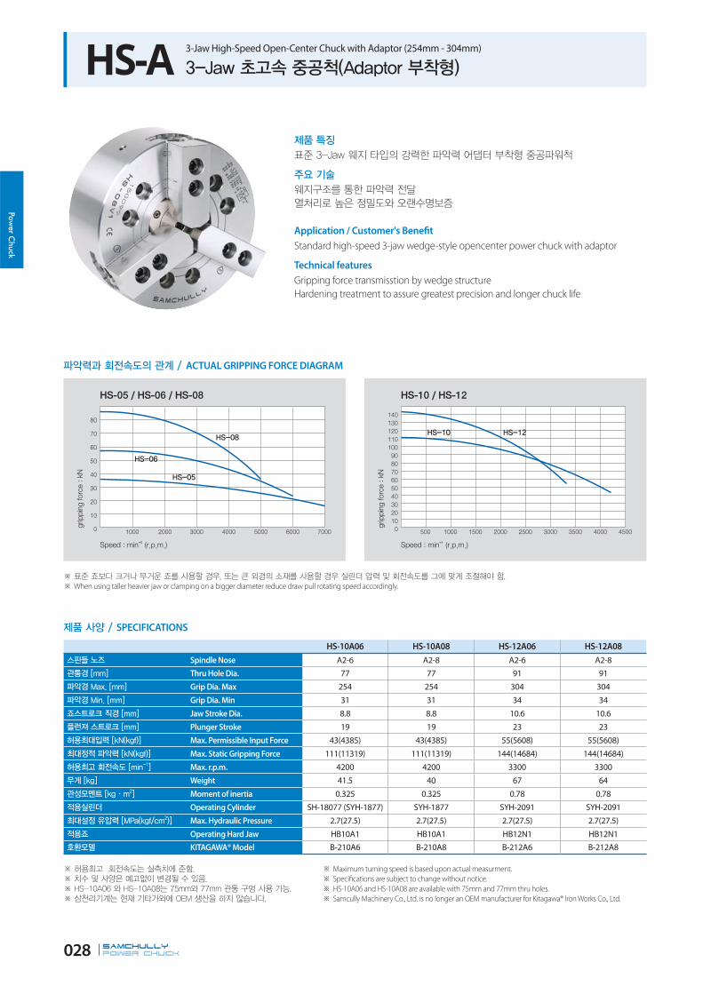
ACTUAL GRIPPING FORCE DIAGRAM
HS-A 3-Jaw High-Speed Open-Center Chuck with Adaptor (254mm - 304mm)
SPECIFICATIONS
Maximum turning speed is based upon actual measurment.
Specifications are subject to change without notice.
HS-10A06 and HS-10A08 are available with 75mm and 77mm thru holes.
Samcully Machinery Co., Ltd. is no longer an OEM manufacturer for Kitagawa® Iron Works Co., Ltd.
HS-10A06 HS-10A08 HS-12A06 HS-12A08
Spindle Nose A2-6 A2-8 A2-6 A2-8
Thru Hole Dia. 77 77 91 91
Grip Dia. Max 254 254 304 304
Grip Dia. Min 31 31 34 34
Jaw Stroke Dia. 8.8 8.8 10.6 10.6
Plunger Stroke 19 19 23 23
Max. Permissible Input Force 43(4385) 43(4385) 55(5608) 55(5608)
Max. Static Gripping Force 111(11319) 111(11319) 144(14684) 144(14684)
Max. r.p.m. 4200 4200 3300 3300
Weight 41.5 40 67 64
Moment of inertia 0.325 0.325 0.78 0.78
Operating Cylinder SH-18077 (SYH-1877) SYH-1877 SYH-2091 SYH-2091
Max. Hydraulic Pressure 2.7(27.5) 2.7(27.5) 2.7(27.5) 2.7(27.5)
Operating Hard Jaw HB10A1 HB10A1 HB12N1 HB12N1
KITAGAWA® Model B-210A6 B-210A8 B-212A6 B-212A8
Application / Customer's Benefit
Standard high-speed 3-jaw wedge-style opencenter power chuck with adaptor
Technical features
Gripping force transmisstion by wedge structure
Hardening treatment to assure greatest precision and longer chuck life
When using taller heavier jaw or clamping on a bigger diameter reduce draw pull rotating speed accordingly.

SAMCHULLYPOWER Chuck 029
Pow
er C
huck
It is recommended to grease chucks at least twice a day in order to maximize longevity.
Blank and machined draw-nuts are available. “U”is Max. Draw nut size.
Refer to Fig-2 for HS-10A06, HS-12A06.
DIMENSIONS
HS-10A06 HS-10A08 HS-12A06 HS-12A08
ΦA 254 254 304 304
B 120 113 129 122
ΦC(H6) 220 220 220 220
ΦD 106.375 139.719 106.375 139.719
E 25 18 25 18
F 5 5 6 6
ΦG 171.4 171.4 171.4 171.4
ΦH 133.4 171.4 133.4 190
ΦJ 77 77 91 91
K 6-M16x100 6-M16x120 6-M16x110 6-M16x130
L 18.5 24 18.5 25
M 30 30 30 30
N max. 51 51 61.3 61.3
N min. 46.6 46.6 56 56
O max. 33.75 33.75 45.75 45.75
O min. 14.25 14.25 15.75 15.75
P max. 33.5 26.5 33 26
P min. 14.5 7.5 10 3
Q 40 40 49 49
R 16 16 21 21
S 25 25 28 28
T 2 2 2 2
U max. M75x2 M85x2 M90x2 M100x2
V 6xM12 3xM8 6xM12 3xM8
ΦW 94 94 108 108
ΦX 45 45 50 50
Y 43 43 50.5 50.5
Z 110 110 111 111
RELATED PRODUCT
170p 78p
H/S Jaw Cylinder

SAMCHULLYPOWER Chuck 030
Power C
huck
HST / HSF 2-Jaw, 4-Jaw High-Speed Open-Center Chuck
ACTUAL GRIPPING FORCE DIAGRAM
SPECIFICATIONS
Maximum turning speed is based upon actual measurment.
Specifications are subject to change without notice.
Samcully Machinery Co., Ltd. is no longer an OEM manufacturer for Kitagawa® Iron Works Co., Ltd.
HST-06 HST-08 HST-10 HST-12 HSF-08 HSF-10 HSF-12
Thru Hole Dia. 46 52 77 91 52 77 91
Grip Dia. Max 169 210 254 304 210 254 304
Grip Dia. Min 15 13 31 34 13 31 34
Jaw Stroke Dia. 5.5 7.4 8.8 10.6 7.4 8.8 10.6
Plunger Stroke 12 16 19 23 16 19 23
Max. Permissible Input Force 14.5 (1479) 23.2 (2366) 28.5 (2906) 36.7 (3742) 23.2 (2366) 28.5 (2906) 36.7 (3742)
Max. Static Gripping Force 38 (3875) 57.3 (5843) 74 (7546) 96 (9789) 57.3 (5843) 74 (7546) 96 (9789)
Max. r.p.m. 6000 5000 4200 3300 5000 4200 3300
Weight 11.5 21.3 33.5 52 22.5 34.5 52
Moment of inertia 0.056 0.165 0.308 0.7 0.18 0.33 0.75
Operating CylinderSH-13046
(SYH-1246)
SH-15052
(SYH-1552)
SH-18077
(SYH-1877)SYH-2091
SH-15052
(SYH-1552)
SH-18077
(SYH-1877)SYH-2091
Max. Hydraulic Pressure 1.85 (18.9) 1.80 (18.4) 1.80 (18.4) 1.81 (18.5) 1.80 (18.4) 1.80 (18.4) 1.80 (28.5)
KITAGAWA® Model BT-206 BT-208 BT-210 BT-212 - - -
Application / Customer's Benefit
2-jaw, 4-jaw high-speed wedge-style open-center power chuck
Technical features
Gripping force transmisstion by wedge structure
Hardening treatment to assure greatest precision and longer chuck life
When using taller heavier jaw or clamping on a bigger diameter reduce draw pull rotating speed accordingly.

SAMCHULLYPOWER Chuck 031
Pow
er C
huck
Blank and machined draw-nuts are available. ‘U’ is Max. Draw nut size.
DIMENSIONS
It is recommended to grease chucks at least twice a day in order to maximize longevity.
HST-06 HST-08 HST-10 HST-12 HSF-08 HSF-10 HSF-12
ΦA 169 210 254 304 210 254 304
B 81 91 100 110 91 100 110
ΦC(H6) 140 170 220 220 170 220 220
F 5 5 5 6 5 5 5
ΦH 104.8 133.4 171.4 171.4 133.4 171.4 171.4
ΦJ 46 52 77 91 52 77 91
K 6-M10x95 6-M12x105 6-M16x100 6-M16x110 4-M10x105 4-M12x120 4-M16x130
M 20 25 30 30 25 30 30
N max. 32 38.7 51 61.3 38.7 51 61.3
N min. 29.25 35 46.6 56 35 46.6 56
O max. 22.75 30 34 45.75 29.75 33.75 45.75
O min. 9.25 15 14.5 15.75 14.75 14.25 15.75
P min -1 -1.5 -10.5 -15 -1.5 -11 -15
P max 11 14.5 8.5 8 14.5 8.5 8
Q 31 35 40 49 35 40 49
R 12 14 16 21 14 16 21
S 19 20.5 25 28 20.5 25 28
Y 2 2 2 2 2 2 2
U max. M55x2.0 M60x2.0 M85x2.0 M100x2.0 M60x2.0 M85x2.0 M100x2.0
ΦV 20 30 45 50 30 45 50
W 29 39 43 50.5 39 43 50.5
X 66 95 110 111 95 110 111
ΦY 60 66 94 108 66 94 108
RELATED PRODUCT
176p 170p 78p
Adaptor H/S Jaw Cylinder

SAMCHULLYPOWER Chuck 032
Power C
huck
HSL 3-Jaw High-Speed Open-Center Long-Stroke Chuck
ACTUAL GRIPPING FORCE DIAGRAM
SPECIFICATIONS
Maximum turning speed is based upon actual measurment.
Specifications are subject to change without notice.
Samcully Machinery Co., Ltd. is no longer an OEM manufacturer for Kitagawa® Iron Works Co., Ltd.
HSL-06 HSL-08 HSL-10 HSL-12
Thru Hole Dia. 33 46 53 63
Grip Dia. Max 169 215 254 304
Grip Dia. Min 28 32 42 43
Jaw Stroke Dia. 20.2 25.4 30 36
Plunger Stroke 15 22 25 30
Max. Permissible Input Force 27.9(2845) 41.1(4191) 53.8(5486) 69.3(7067)
Max. Static Gripping Force 31.2(3182) 49.0(4997) 63.0(6427) 80.4(8199)
Max. r.p.m. 4500 3300 3000 2200
Weight 14 25 45 78
Moment of inertia 0.043 0.198 0.306 0.918
Operating Cylinder SH-13046 (SYH-1246) SH-15052 (SYS-1552) SH-18077 (SYH-1877) SYH-2091
Max. Hydraulic Pressure 3.40(34.7) 2.99(30.5) 3.20(32.6) 3.22(32.8)
Operating Hard Jaw HB06A1 HB08A1 HB10A1 HB12N1
KITAGAWA® Model BL-206 BL-208 BL-210 BL-212
Application / Customer's Benefit
Long-stroke high-speed 3-jaw wedge-style open-center power chuck
Technical features
Gripping force transmisstion by wedge structure
Hardening treatment to assure greatest precision and longer chuck life
When using taller heavier jaw or clamping on a bigger diameter reduce draw pull rotating speed accordingly.

SAMCHULLYPOWER Chuck 033
Pow
er C
huck
Blank and machined draw-nuts are available. ‘U’ is Max. Draw nut size.
DIMENSIONS
It is recommended to grease chucks at least twice a day in order to maximize longevity.
HSL-06 HSL-08 HSL-10 HSL-12
ΦA 169 215 254 304
B 84 99 110 130
ΦC(H6) 140 170 220 220
F 5 5 5 6
ΦH 104.8 133.4 171.4 171.4
ΦJ 33 46 53 63
K 6-M10 6-M10 6-M16 6-M16
M 20 25 30 30
N max. 39.3 52.3 62 72.4
N min. 29.2 39.6 46.9 54.4
O max. 16.75 20.7 26.2 38.2
O min. 9.25 11.5 9.7 8.2
P max. 14 15.5 14.5 15
P min. -1 -6.5 -10.5 -15
Q 31 35 40 49
R 12 14 16 21
S 19 22.5 25 28
T 2 2 2 3
U max. M42x1.5 M55x2.0 M65x2.0 M75x2.0
W 47 66 80 83
ΦX 20 30 45 50
Y 32.5 39 43 50.5
Z 72 95 110 111
RELATED PRODUCT
176p 170p 78p
Adaptor H/S Jaw Cylinder

SAMCHULLYPOWER Chuck 034
Power C
huck
MH Standard Mega Bore 3-Jaw High-Speed Open-Center Chuck
MH-206 MH-208 MH-210 MH-212 MH-218 MH-221 MH-224
Thru Hole Dia. 52 66 82 103 166.5 166.5 190
Grip Dia. Max 175 210 254 315 457 530 610
Grip Dia. Min. 16.5 23 30 54 73 105 120
Jaw Stroke Dia. 6.4 7.4 8.8 10.6 11.5 10.6 10.6
Plunger Stroke 15 17.5 19 23 25 23 23
Max. Permissible Input Force 24.7(2551) 36.4(3596) 49(4976) 55(5608) 71(7240) 90(9177) 90(9177)
Max. Static Gripping Force 57.3(5847) 87(8872) 126.6(12848) 144(14686) 180(18355) 220(22460) 234(23861)
Max. r.p.m. 6000 5000 4500 3000 2000 1700 1400
Weight 11.9 23 32 55.3 170 228 293
Moment of inertia 0.05 0.143 0.312 0.736 4.45 8.7 16.6
Operating CylinderSH-15052
(SYH-1552)
SH-17068
(SYH-1768)SH-19082 SH-21010 SYHL-2816 SYHL-2816 SHL-39024
Max. Hydraulic Pressure 1.78(18.1) 2.34(23.9) 2.74(28) 2.65(27.2) 3.07(32) 2.86(29.1) 1.57(16.1)
Operating Hard Jaw HB06A1 HB08A1 HB10A1 HB12N1 HB15A1 HB18B2 HB18B2
ACTUAL GRIPPING FORCE DIAGRAM
SPECIFICATIONS
Maximum turning speed is based upon actual measurment.
Specifications are subject to change without notice.
Samcully Machinery Co., Ltd. is no longer an OEM manufacturer for Kitagawa® Iron Works Co., Ltd.
Application / Customer's Benefit
Mega-bore 3-jaw wedge-style, open-center power chuck
Technical features
Gripping force transmisstion by wedge structure
Hardening treatment to assure greatest precision and longer chuck life
When using taller heavier jaw or clamping on a bigger diameter reduce draw pull rotating speed accordingly.

SAMCHULLYPOWER Chuck 035
Pow
er C
huck
Blank and machined draw-nuts are available. ‘K’ is Max. Draw nut size.
DIMENSIONS
It is recommended to grease chucks at least twice a day in order to maximize longevity.
MH-206 MH-208 MH-210 MH-212 MH-218 MH-221 MH-224
ΦA 175 210 254 315 457 530 610
B 81 91 100 110 135 140 149
ΦC(H6) 140 170 220 300 380 380 380
ΦD 104.8 133.4 171.4 235 300.2 330.2 330.2
E 5 5 5 6 6 6 6
ΦF 52 66 82 103 166.5 166.5 190
G max. 14 7.5 8.5 8 8 11 20
G min. -1 -10 -10.5 -15 -23 -12 -3
H 17.5 27 25 28 50 39 40.5
ΦJ 20 30 52 82.5 107 80 80
K max. M60x2.0 M75x2.0 M90x2.0 M116x2.0 M175x3.0 M180x3.0 M200x3.0
L 3-M10x95 6-M12x115 6-M16x120 6-M20x130 6-M20x130 6-M22x140 6-M22x150
M 33 39 43 51 69 73 73
N 72 95 110 111 165 180 180
P 20 25 30 30 50 60 60
Q max. 38 45.7 54.5 67.3 102 111.75 119.5
Q min. 34.8 42 50.1 62 96.25 106.5 114.2
R max. 21.75 23.75 32.25 45.75 58.25 72.5 105.5
R min. 10.25 11.75 14.25 15.75 20.25 21.5 21.5
T 31 35 40 49 69 65 65
U 12 14 16 21 22 25 25
V 2 2 2 2 5 5 5
ΦW 65 80 101 124 186 197 210
RELATED PRODUCT
176p 170p 78p
Adaptor H/S Jaw Cylinder

SAMCHULLYPOWER Chuck 036
Power C
huck
MHT / MHF Mega Bore 2-Jaw / 4-Jaw Ultrahigh-Speed Open-Center Chuck
ACTUAL GRIPPING FORCE DIAGRAM
SPECIFICATIONS
Maximum turning speed is based upon actual measurment.
Specifications are subject to change without notice.
Samcully Machinery Co., Ltd. is no longer an OEM manufacturer for Kitagawa® Iron Works Co., Ltd.
MHT-206 MHT-208 MHF-208
Thru Hole Dia. 52 66 66
Grip Dia. Max 175 210 210
Grip Dia. Min 16.5 23 23
Jaw Stroke Dia. 6.4 7.4 7.4
Plunger Stroke 15 17.5 17.5
Max. Permissible Input Force 16.6(1700) 23.5(2397) 23.25(2397)
Max. Static Gripping Force 38(3875) 57.9(5914) 57.9(5914)
Max. r.p.m. 6000 5000 5000
Weight 11.5 21.7 23.5
Moment of inertia 0.055 0.16 0.14
Operating Cylinder SYH-15052 (SYH-1552) SH-17068 (SYH-1768) SH-17068 (SYH-1768)
Max. Hydraulic Pressure 1.18(12) 1.59(16.3) 1.59(163.3)
Operating Hard Jaw HB06A1 HB08A1 HBF08A1
KITAGAWA® Model - - -
Application / Customer's Benefit
Mega Bore 2-jaw, 4-jaw high-speed wedge-style, open-center power chuck
Technical features
Gripping force transmisstion by wedge structure
Hardening treatment to assure greatest precision and longer chuck life
When using taller heavier jaw or clamping on a bigger diameter reduce draw pull rotating speed accordingly.

SAMCHULLYPOWER Chuck 037
Pow
er C
huck
Blank and machined draw-nuts are available. ‘K’ is Max. Draw nut size.
DIMENSIONS
It is recommended to grease chucks at least twice a day in order to maximize longevity.
MHT-206 MHT-208 MHF-208
ΦA 175 210 210
B 81 91 91
ΦC(H6) 140 170 170
ΦD 104.8 133.4 133.4
E 5 5 5
ΦF 52 66 66
G max. 14 7.5 7.5
G min. -1 -10 -10
H 17.5 27 27
ΦJ 20 30 30
K max. M60x2.0 M75x2.0 M75x2.0
L 6-M10x 95 6-M12x115 4-M12x115
M 32.5 39 39
N 72 95 95
P 20 25 25
Q max. 38 45.7 45.7
Q min. 34.8 42 42
R max. 21.75 23.75 23.75
R min. 10.25 11.75 11.75
T 31 35 35
U 12 14 14
V 2 2 2
ΦW 65 80 80
RELATED PRODUCT
176p 170p 78p
Adaptor H/S Jaw Cylinder

SAMCHULLYPOWER Chuck 038
Power C
huck
HCH Standard 3-Jaw Open-Center Chuck (110mm - 450mm)
ACTUAL GRIPPING FORCE DIAGRAM
SPECIFICATIONS
Maximum turning speed is based upon actual measurment.
Specifications are subject to change without notice.
Samcully Machinery Co., Ltd. is no longer an OEM manufacturer for Kitagawa® Iron Works Co., Ltd.
HCH-04 HCH-12 HCH-15 HCH-18
Thru Hole Dia. 21 78 117.5 117.5
Grip Dia. Max 110 304 381 450
Grip Dia. Min 5 19 30 30
Jaw Stroke Dia. 4.2 10.6 10.6 10.6
Plunger Stroke 6.5 23 23 23
Max. Permissible Input Force 8(800) 49(4997) 71(7240) 71(7240)
Max. Static Gripping Force 13(1350) 129(13150) 180(18355) 180(18355)
Max. r.p.m. 5500 3000 2500 2000
Weight 3.7 63 120 164
Moment of inertia 0.006 0.75 2.25 4.45
Operating Cylinder HYH-0933 SH-19082 SH-25011 SH-25011
Max. Hydraulic Pressure 2.2(22.4) 2.3(23.5) 2.3(23.5) 2.3(23.5)
Operating Hard Jaw HB04A1 HB12B1 HB15A1 HB15A1
KITAGAWA® Model B-04 B-12 B-15 B-18
Application / Customer's Benefit
Standard 3-jaw wedge-style open-center chuck
Technical features
Gripping force transmisstion by wedge structure
Hardening treatment to assure greatest precision and longer chuck life
When using taller heavier jaw or clamping on a bigger diameter reduce draw pull rotating speed accordingly.

SAMCHULLYPOWER Chuck 039
Pow
er C
huck
Blank and machined draw-nuts are available. ‘U’ is Max. Draw nut size.
DIMENSIONS
It is recommended to grease chucks at least twice a day in order to maximize longevity.
HCH-04 HCH-12 HCH-15 HCH-18
ΦA 110 304 381 450
B 54 110 133 133
ΦC(H6) 85 220 300 380
F 4 6 6 6
H 70.6 171.4 235 235
ΦJ 21 78 117.5 117.5
K 3-M10 6-M16 6-M20 6-M20
L 15.5 23 50 30
M 15 30 43 43
N max. 20 58 82 82
N min. 17.9 52.7 76.7 76.7
O max. 14.25 48.75 43.75 78.25
O min. 6.75 12.75 18.25 18.25
P max. 3.5 8 11 11
P min. -3 -15 -12 -12
Q 19 49 62 62
R 8 18 22 22
S 15 38 39 39
T 2 5 5 5
U max. M28x1.5 M88x2.0 M130x2.0 M130x2.0
ΦV 10 50 60 60
W 24 54 70 70
X 48 129 165 165
ΦY 34 96 139 139
RELATED PRODUCT
176p 170p 78p
Adaptor H/S Jaw Cylinder

SAMCHULLYPOWER Chuck 040
Power C
huck
HCH Standard 3-Jaw Open-Center Chuck (530mm-800mm)
ACTUAL GRIPPING FORCE DIAGRAM
SPECIFICATIONS
Maximum turning speed is based upon actual measurment.
Specifications are subject to change without notice.
Samcully Machinery Co., Ltd. is no longer an OEM manufacturer for Kitagawa® Iron Works Co., Ltd.
HCH-21 HCH-24 HCH-32
Thru Hole Dia. 140 165 240
Grip Dia. Max 530 610 800
Grip Dia. Min 87 110 240
Jaw Stroke Dia. 10.6 10.6 18
Plunger Stroke 23 23 34
Max. Permissible Input Force 90(9177) 90(9177) 100(10193)
Max. Static Gripping Force 234(23861) 234(23861) 240(24464)
Max. r.p.m. 1700 1400 1200
Weight 235 293 530
Moment of inertia 8.95 16.6 15.25
Operating Cylinder SH-25011 SYHL-2816 SYHL-2816
Max. Hydraulic Pressure 3.0(30.6) 3.0(30.6) 3.2(33.6)
Operating Hard Jaw HB18B2 HB18B2 HB32B2
KITAGAWA® Model B-21 B-24 -
Application / Customer's Benefit
Standard 3-jaw wedge-style open-center chuck
Technical features
Gripping force transmisstion by wedge structure
Hardening treatment to assure greatest precision and longer chuck life
When using taller heavier jaw or clamping on a bigger diameter reduce draw pull rotating speed accordingly.

SAMCHULLYPOWER Chuck 041
Pow
er C
huck
Blank and machined draw-nuts are available. ‘U’ is Max. Draw nut size.
DIMENSIONS
It is recommended to grease chucks at least twice a day in order to maximize longevity.
HCH-21 HCH-24 HCH-32
ΦA 530 610 800
B 140 149 150
ΦC(H6) 380 380 520
F 6 6 6
H 330.2 330.2 463.6
ΦJ 140 165 240
K 6-M22 6-M22 6-M24
L 31 32 31
M 60 60 38
N max. 98.5 108 162.6
N min. 93.2 102.7 153.6
O max. 87.5 117.5 182
O min. 21.5 21.5 20
P max. 11 20 29
P min. -12 -3 -5
Q 65 65 75
R 25 25 25.5
S 39 40 34.5
T 5 5 10
U max. M155x3.0 M175x3.0 M250x3.0
ΦV 80 80 80
W 72 72 83
X 180 180 160
ΦY 170 187 260
RELATED PRODUCT
176p 170p 84p
Adaptor H/S Jaw Cylinder

SAMCHULLYPOWER Chuck 042
Power C
huck
HCH-A 3-Jaw Open-Center Chuck with adaptor (304mm - 381mm)
ACTUAL GRIPPING FORCE DIAGRAM
SPECIFICATIONS
Maximum turning speed is based upon actual measurment.
Specifications are subject to change without notice.
Samcully Machinery Co., Ltd. is no longer an OEM manufacturer for Kitagawa® Iron Works Co., Ltd.
HCH-12A06 HCH-12A08 HCH-15A08 HCH-15A11
Spindle Nose A2-6 A2-8 A2-8 A2-11
Thru Hole Dia. 78 78 117.5 117.5
Grip Dia. Max 304 304 381 381
Grip Dia. Min 19 19 30 30
Jaw Stroke Dia. 10.6 10.6 10.6 10.6
Plunger Stroke 23 23 23 23
Max. Permissible Input Force 49(4997) 49(4997) 71(7240) 71(7240)
Max. Static Gripping Force 129(13150) 129(13150) 180(18355) 180(18355)
Max. r.p.m. 3000 3000 2500 2500
Weight 69 66 134 127
Moment of inertia 0.8 0.8 2.47 2.47
Operating Cylinder SYH-2091 SYH-2091 SH-25011 SH-25011
Max. Hydraulic Pressure 2.3(23.5) 2.3(23.5) 2.3(23.5) 2.3(23.5)
Operating Hard Jaw HB12B1 HB12B1 HB15A1 HB15A1
KITAGAWA® Model B-12A6 B-12A8 B-15A8 B-15A11
Application / Customer's Benefit
3-jaw wedge-style power chuck with adaptor plate
Technical features
Gripping force transmisstion by wedge structure
Hardening treatment to assure greatest precision and longer chuck life
When using taller heavier jaw or clamping on a bigger diameter reduce draw pull rotating speed accordingly.

SAMCHULLYPOWER Chuck 043
Pow
er C
huck
DIMENSIONS
It is recommended to grease chucks at least twice a day in order to maximize longevity.
HCH-12A06 HCH-12A08 HCH-15A08 HCH-15A11
ΦA 304 304 381 381
B 129 122 160 149
ΦC(H6) 220 220 300 300
ΦD 106.375 139.719 139.719 196.869
E 25 18 33 22
F 6 6 6 6
ΦG 171.4 190 235 260
ΦH 133.4 171.4 171.4 235
ΦJ 78 78 117.5 117.5
K 6-M16x110 6-M16x130 6-M20x130 6-M20x150
L 18.5 25 24 28
M 30 30 43 43
N max. 58 58 82 82
N min. 52.7 52.7 76.7 76.7
O max. 48.75 48.75 43.75 43.75
O min. 12.75 12.75 18.25 18.25
P max. 33 26 44 33
P min. 10 3 21 10
Q 49 49 62 62
R 18 18 22 22
S 38 38 39 39
T 5 5 5 5
U max. M88x2.0 M88x2.0 M130x2.0 M130x2.0
V 6-M12 3-M8 6-M16 3-M10
ΦW 50 50 60 60
X 53.5 53.5 70 70
Y 129 129 165 165
ΦZ 96 96 139 139
Blank and machined draw-nuts are available. “U”is Max. Draw nut size.
Refer to Fig-2 for HCH-12A06, HCH-12A08.
RELATED PRODUCT
170p 82p
H/S Jaw Cylinder

SAMCHULLYPOWER Chuck 044
Power C
huck
HCH-A 3-Jaw Open-Center Chuck with adaptor (450mm - 610mm)
ACTUAL GRIPPING FORCE DIAGRAM
SPECIFICATIONS
Maximum turning speed is based upon actual measurment.
Specifications are subject to change without notice.
Samcully Machinery Co., Ltd. is no longer an OEM manufacturer for Kitagawa® Iron Works Co., Ltd.
HCH-18A11 HCH-21A15 HCH-24A15
Spindle Nose A2-11 A2-15 A2-15
Thru Hole Dia. 117.5 140 165
Grip Dia. Max 450 530 610
Grip Dia. Min 30 87 110
Jaw Stroke Dia. 10.6 10.6 10.6
Plunger Stroke 23 23 23
Max. Permissible Input Force 71(7240) 90(91770) 90(9177)
Max. Static Gripping Force 180(18355) 234(23861) 234(23861)
Max. r.p.m. 2000 1700 1400
Weight 178 246 304
Moment of inertia 4.775 9.25 16.85
Operating Cylinder SH-25011 SH-25011 SYHL-2816
Max. Hydraulic Pressure 2.3(23.5) 3.0(30.6) 3.0(30.6)
Operating Hard Jaw HB15A1 HB18B2 HB18B2
KITAGAWA® Model B-18A11 B-21A15 B-24A15
Application / Customer's Benefit
3-jaw wedge-style power chuck with adaptor plate
Technical features
Gripping force transmisstion by wedge structure
Hardening treatment to assure greatest precision and longer chuck life
When using taller heavier jaw or clamping on a bigger diameter reduce draw pull rotating speed accordingly.

SAMCHULLYPOWER Chuck 045
Pow
er C
huck
DIMENSIONS
It is recommended to grease chucks at least twice a day in order to maximize longevity.
HCH-18A11 HCH-21A15 HCH-24A15
ΦA 450 530 610
B 149 161 170
ΦC(H6) 380 380 380
ΦD 196.869 285.775 285.775
E 22 27 27
F 6 6 6
ΦG 320 330.2 330.2
ΦH 235 330.2 330.2
ΦJ 117.5 140 165
K 6-M20x150 6-M22x170 6-M22x180
L 28 34 35
M 43 60 60
N max. 82 98.5 108
N min. 76.7 93.2 102.7
O max. 78.28 87.5 117.5
O min. 18.25 21.5 21.5
P max. 33 38 47
P min. 10 15 24
Q 62 65 65
R 22 25 25
S 39 39 40
T 5 5 5
U max. M130x2.0 M155x3.0 M175x3.0
V 3-M10 3-M12 3-M12
ΦW 60 80 80
X 70 72 72
Y 165 180 180
ΦZ 139 170 187
Blank and machined draw-nuts are available. “U”is Max. Draw nut size.
HCH-21A15 and HCH24A15 are available with M22 or M24 mounting bolts.
RELATED PRODUCT
170p 78p
H/S Jaw Cylinder
SAMCHULLYPOWER Chuck 046
Power C
huck
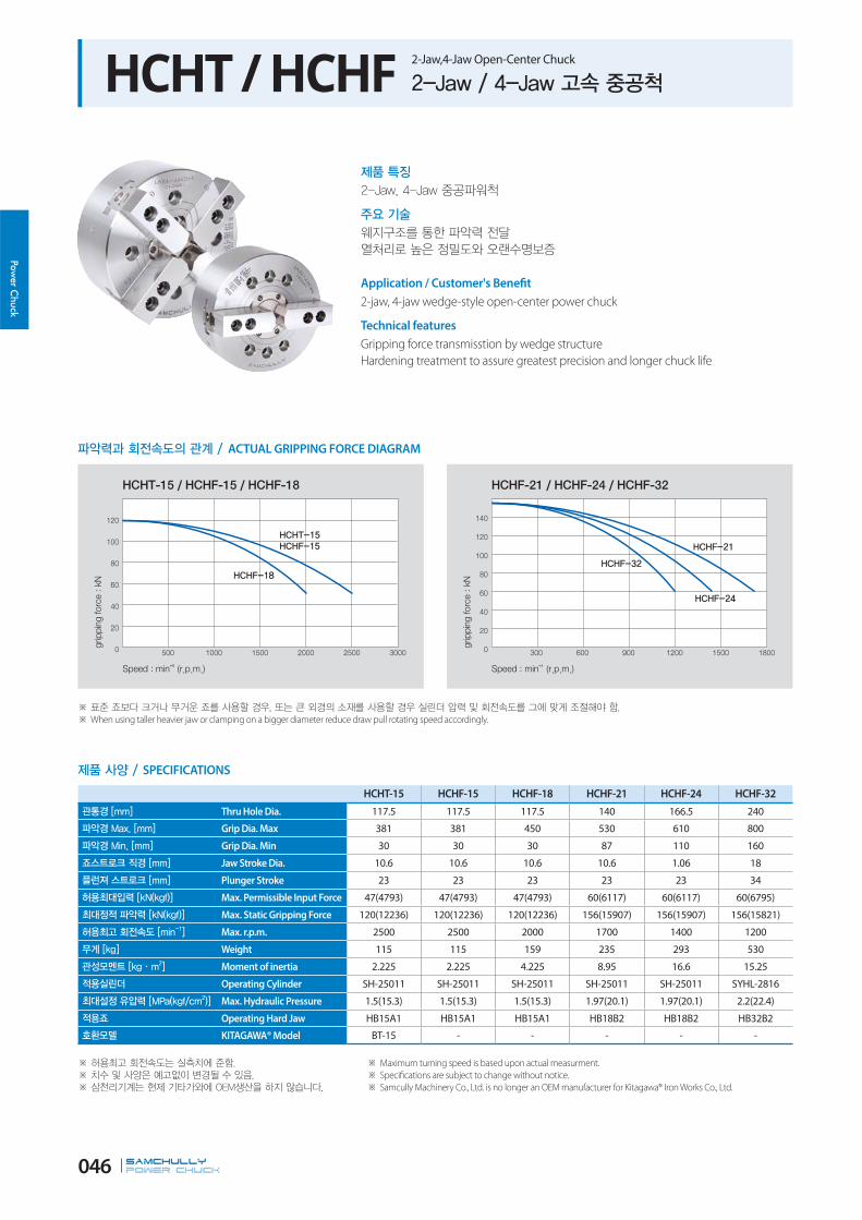
HCHT / HCHF 2-Jaw,4-Jaw Open-Center Chuck
ACTUAL GRIPPING FORCE DIAGRAM
SPECIFICATIONS
Maximum turning speed is based upon actual measurment.
Specifications are subject to change without notice.
Samcully Machinery Co., Ltd. is no longer an OEM manufacturer for Kitagawa® Iron Works Co., Ltd.
HCHT-15 HCHF-15 HCHF-18 HCHF-21 HCHF-24 HCHF-32
Thru Hole Dia. 117.5 117.5 117.5 140 166.5 240
Grip Dia. Max 381 381 450 530 610 800
Grip Dia. Min 30 30 30 87 110 160
Jaw Stroke Dia. 10.6 10.6 10.6 10.6 1.06 18
Plunger Stroke 23 23 23 23 23 34
Max. Permissible Input Force 47(4793) 47(4793) 47(4793) 60(6117) 60(6117) 60(6795)
Max. Static Gripping Force 120(12236) 120(12236) 120(12236) 156(15907) 156(15907) 156(15821)
Max. r.p.m. 2500 2500 2000 1700 1400 1200
Weight 115 115 159 235 293 530
Moment of inertia 2.225 2.225 4.225 8.95 16.6 15.25
Operating Cylinder SH-25011 SH-25011 SH-25011 SH-25011 SH-25011 SYHL-2816
Max. Hydraulic Pressure 1.5(15.3) 1.5(15.3) 1.5(15.3) 1.97(20.1) 1.97(20.1) 2.2(22.4)
Operating Hard Jaw HB15A1 HB15A1 HB15A1 HB18B2 HB18B2 HB32B2
KITAGAWA® Model BT-15 - - - - -
Application / Customer's Benefit
2-jaw, 4-jaw wedge-style open-center power chuck
Technical features
Gripping force transmisstion by wedge structure
Hardening treatment to assure greatest precision and longer chuck life
When using taller heavier jaw or clamping on a bigger diameter reduce draw pull rotating speed accordingly.

SAMCHULLYPOWER Chuck 047
Pow
er C
huck
RELATED PRODUCT
176p 170p 78p
Adaptor H/S Jaw Cylinder
Blank and machined draw-nuts are available. ‘K’ is Max. Draw nut size.
DIMENSIONS
H F
It is recommended to grease chucks at least twice a day in order to maximize longevity.
HCHT-15 HCHF-15 HCHF-18 HCHF-21 HCHF-24 HCHF-32
ΦA 381 381 450 530 610 800
B 133 133 133 140 149 150
ΦC(H6) 300 300 380 380 380 520
ΦD 235 235 235 330.2 330.2 463.6
E 6 6 6 6 6 6
ΦF 117.5 118 118 140 165 240
G max. 11 11 11 11 20 34
G min. -12 -12 -12 -12 -3 0
H 39 39 39 39 40 34.5
ΦJ 60 60 60 80 80 80
K max. M130x2.0 M130x2.0 M130x2.0 M155x3.0 M175x3.0 M250x3.0
L 6-M20x150 4-M20x150 4-M20x130 8-M22x140 8-M22x150 8-M24x130
M 70 70 70 72 72 83
N 165 165 165 180 180 160
P 43 43 43 60 60 38
Q max. 82 82 82 98.5 102.7 162.6
Q min. 76.7 76.7 76.7 93.2 108 153.6
R max. 43.75 43.75 78.25 87.5 117.5 182
R min. 18.25 18.25 18.25 21.5 21.5 20
T 62 62 62 65 65 75
U 22 22 22 25 25 25.5
V 5 5 5 5 5 3.5
ΦW 139 139 136 170 187 260

SAMCHULLYPOWER Chuck 048
Power C
huck
HC Standard 3-Jaw Closed-Center Chuck (110mm - 304mm)
ACTUAL GRIPPING FORCE DIAGRAM
SPECIFICATIONS
Maximum turning speed is based upon actual measurment.
Specifications are subject to change without notice.
Samcully Machinery Co., Ltd. is no longer an OEM manufacturer for Kitagawa® Iron Works Co., Ltd.
HC-04 HC-05 HC-06 HC-08 HC-10 HC-12
Jaw Stroke Dia. 6.4 6.4 8.5 8.8 8.8 10.5
Plunger Stroke 14 14 18.5 19 25 30
Grip Dia. Max 110 135 165 210 254 304
Grip Dia. Min 8 16 19 23 24 26
Max. Permissible Input Force 8.2(836) 8.2(836) 18(1835) 25(2549) 29(2957) 41(4181)
Max. Static Gripping Force 22.8(2325) 25.2(2570) 52.5(5353) 75(7648) 108(11013) 156(15907)
Max. r.p.m. 6000 5500 5270 4760 4010 3380
Weight 4.1 6.2 13 25 37 57.3
Moment of inertia 0.007 0.015 0.045 0.138 0.3 0.725
Max. Hydraulic Pressure 2.4(24.5) 2.4(24.5) 2.6(26.5) 2.5(25.5) 2.8(28.6) 2.7(27.5)
Operating Cylinder Hydraulic Y-0715R(RE) Y-0715R(RE) Y-1020R(RE) Y-1225R(RE) Y-1225R(RE) Y-1530R(RE)
Operating Cylinder Pneumatic AY-1315R AY-1315R AY-1720R AY-2225R AY-2225R AY-2730R
Operating Hard Jaw HB04N1 HB04N1 HB06A1 HB08A1 HB10A1 HB12B1
KITAGAWA® Model N-04 N-05 N-06 N-08 N-10 N-12
Application / Customer's Benefit
Standard 3-jaw wedge-style closed-center power chuck
Technical features
Gripping force transmisstion by wedge structure
Hardening treatment to assure greatest precision and longer chuck life
When using taller heavier jaw or clamping on a bigger diameter reduce draw pull rotating speed accordingly.

SAMCHULLYPOWER Chuck 049
Pow
er C
huck
RELATED PRODUCT
176p 170p 92p
Adaptor H/S Jaw Cylinder
The numbers in parentheses in columns P and T are also available upon request.
DIMENSIONS
It is recommended to grease chucks at least twice a day in order to maximize longevity.
HC-04 HC-05 HC-06 HC-08 HC-10 HC-12
ΦA 110 135 165 210 254 304
B 52 55 74 85 89 106
ΦC(H6) 60 80 140 170 220 220
F 6 7 5 5 5 6
ΦH 80 100 104.8 133.4 171.4 171.4
ΦJ - - 21 25 34 34
K 3-M8x55 3-M8x60 6-M10x90 6-M12x100 6-M16X105 6-M16x120
L 12 14 14 20 38 38
M 14 19 20 25 30 30
N max. 23.3 30.4 37.8 46.3 51.1 61
N min. 20.1 27.2 33.5 41.9 46.7 55.75
O max. 11.25 11.25 18 22.25 30.75 48.75
O min. 8.25 6.75 7.5 9 11.25 12.75
P max. 17 6 100 109(125) 119(158) 142(163)
P min. 3 -8 81.5 90(100) 94(133) 112(133)
Q 23 23 31 35 40 50
R 10 10 12 14 16 18
S 25 35 36 36 36 36
T M10x1.5 M12x1.75 M16x2.0 M20x2.5 M20x2.5 M24x3.0 / M20x2.5
U 3 3 4 5 5 5
ΦV 26 28 34 38 45 50
W 27 29 35 42 46 54
X 55 62 72 95 110 129

SAMCHULLYPOWER Chuck 050
Power C
huck
HC Standard 3-Jaw Closed-Center Chuck (381mm - 1000mm)
ACTUAL GRIPPING FORCE DIAGRAM
SPECIFICATIONS
Maximum turning speed is based upon actual measurment.
Specifications are subject to change without notice.
Samcully Machinery Co., Ltd. is no longer an OEM manufacturer for Kitagawa® Iron Works Co., Ltd.
HC-15 HC-18 HC-21 HC-24 HC-32S HC-40S
Jaw Stroke Dia. 16 16 16 16 20 30
Plunger Stroke 35 35 35 35 38 23
Grip Dia. Max 381 450 530 610 800 1000
Grip Dia. Min 71 133 62 152 200 330
Max. Permissible Input Force 82(8362) 82(8362) 82(8362) 82(8362) 100(12236) 180(18256)
Max. Static Gripping Force 249(25391) 249(25391) 273(27838) 273(27838) 240(21805) 320(32454)
Max. r.p.m. 3040 2710 1940 1760 800 630
Weight 96 124 180 223 350 600
Moment of inertia 1.8 2.35 4.8 6.925 15.25 36.4
Max. Hydraulic Pressure 3.2(32.6) 3.2(32.6) 3.2(32.6) 3.2(32.6) 3.99(40.8) 3.99(40.8)
Operating Cylinder Hydraulic Y-2035R(RE) Y-2035R(RE) Y-2035R(RE) Y-2035R(RE) Y-2050R(RE) Y-2560RE
Operating Hard Jaw HB15N1 HB15N1 HB18B2 HB18B2 HB32SB2 HB40SB2
KITAGAWA® Model N-15 N-18 N-21 N-24 - -
Application / Customer's Benefit
Standard 3-jaw wedge-style closed-center power chuck
Technical features
Gripping force transmisstion by wedge structure
Hardening treatment to assure greatest precision and longer chuck life
When using taller heavier jaw or clamping on a bigger diameter reduce draw pull rotating speed accordingly.

SAMCHULLYPOWER Chuck 051
Pow
er C
huck
DIMENSIONS
It is recommended to grease chucks at least twice a day in order to maximize longevity.
HC-15 HC-18 HC-21 HC-24 HC-32S HC-40S
ΦA 381 450 530 610 800 1000
B 114 114 125 125 150 180
ΦC(H6) 300 300 380 380 380 520
F 6 6 6 6 6 8
ΦH 235 235 330.2 330.2 330.2 463.6
ΦJ 27 27 27 27 65 50
K 6-M20X150 6-M20X115 6-M22X120 6-M22X120 6-M24X120 6-M24X120
L 65 30 31 31 39 32
M 43 43 60 60 76.2 76.2
N max. 77.5 108 86 125 117.3 212.8
N min. 69.5 100 78 117 102.3 187.8
O max. 48.75 48.75 93.5 93.5 234.1 169.8
O min. 23.25 23.25 27.5 27.5 36 17.4
P max. 104 92 97 97 38 30
P min. 69 57 62 62 0 -27
Q 62 62 65 65 75 110
R 25.5 25.5 25 25 12.7 30
S 55 55 55 55 70 65
T M30x3.5 M30x3.5 M30x3.5 M30x3.5 M30x3.5 M36x4.0
U 2 2 3 3 8 -4
ΦV 60 60 60 60 70 70
W 61 61 70 71 81 106
X 135 135 180 180 165 270
RELATED PRODUCT
176p 170p 92p
Adaptor H/S Jaw Cylinder

SAMCHULLYPOWER Chuck 052
Power C
huck
HC (groove type)3-Jaw Hydraulic / 4-Jaw Independent Chuck (800mm -1600mm)
ACTUAL GRIPPING FORCE DIAGRAM
SPECIFICATIONS
Maximum turning speed is based upon actual measurment.
Specifications are subject to change without notice.
HC-32G HC-40G HC-50G HC-55G HC-63G
Jaw Stroke Dia. 30 46 46 48 48
Manual Setting 30 30 30 40 40
Plunger Stroke 38 57 57 60 60
Grip Dia. Max 800 1000 1250 1400 1600
Grip Dia. Min 200 330 330 460 460
Max. Permissible Input Force 100 (12170) 180 (18256) 180 (18256) 200 (20394) 200 (20394)
Max. Static Gripping Force 240 (21805) 320 (32454) 320 (32454) 360 (36710) 360 (36710)
Max. r.p.m. 800 630 500 450 400
Weight 350 600 800 1350 1850
Moment of inertia 15.25 43.625 55 70 125
Operating Cylinder Y-2050RE Y-2560RE Y-2560RE Y-2560RE Y-2560RE
Max.Hydraulic Pressure 3.99(40.8) 3.99(40.8) 3.99(40.8) 4.5(46) 4.5(46)
Operating Hard Jaw HB32GB HB40GB HB40GB HB40GB HB40GB
Application / Customer's Benefit
3-Jaw Power Chuck (HC-32G,HC-40G)
4-jaw independent closed-center power chuck (HC-50G,HC-55G,HC-63G)
Technical features
Gripping force transmisstion by wedge structure
Hardening treatment to assure greatest precision and longer chuck life
When using taller heavier jaw or clamping on a bigger diameter reduce draw pull rotating speed accordingly.

SAMCHULLYPOWER Chuck 053
Pow
er C
huck
HC-32, HC-40 19.025mm key Groove type.
DIMENSIONS
It is recommended to grease chucks at least twice a day in order to maximize longevity.
HC-32G HC-40G HC-50G HC-55G HC-63G
ΦA 800 1000 1250 1400 1600
B 150 182 180 220 220
ΦC(H6) 380 520 520 720 720
F 6 8 8 8 8
G 442.5 509.6 623.9 710.6 786.8
ΦH 330.2 463.6 463.6 647.6 647.6
K M24X120L M24X140L M24X140L M24X160L M24X160L
L 39 32 32 36 36
M 76.2 76.2 76.2 76.2 76.2
N max. 117.6 217.3 217.3 250 250
N min. 102.7 194.3 194.3 226 226
O max. 196.9 91.1 205.4 250.4 335.6
O min. 44.5 14.9 14.9 30.8 30.8
P max. 38 60 60 82 13
P min. 0 3 3 22 22
Q 75 110 110 110 110
S 70 65 65 65 65
S1 35 35 35 35 35
T M30x3.5 M36x4.0 M36x4.0 M36x4.0 M36x4.0
ΦV 55 70 70 70 70
W 83 106 106 104 104
X 165 270 270 270 270
a1 12.7 30 30 30 30
a2 8 -4 -4 -6 -6
a3 3 4 4 4 4
a4 75 85 85 110 110
RELATED PRODUCT
176p 170p 92p
Adaptor H/S Jaw Cylinder

SAMCHULLYPOWER Chuck 054
Power C
huck
HC-A 3-Jaw Closed-Center Chuck with Adaptor (165mm - 304mm)
ACTUAL GRIPPING FORCE DIAGRAM
SPECIFICATIONS
Refer to Fig-2 for HC-10A06 and HC-12A06.
Maximum turning speed is based upon actual measurment.
Specifications are subject to change without notice.
Samcully Machinery Co., Ltd. is no longer an OEM manufacturer for Kitagawa® Iron Works Co., Ltd.
HC-06A05 HC-08A06 HC-10A06 HC-10A08 HC-12A06 HC-12A08
Spindle Nose No. A2-5 A2-6 A2-6 A2-8 A2-6 A2-8
Jaw Stroke Dia. 8.5 8.8 8.8 8.8 10.5 10.5
Plunger Stroke 18.5 19 25 25 30 30
Grip Dia. Max 165 210 254 254 304 304
Grip Dia. Min 19 23 24 224 26 26
Max. Permissible Input Force 18(1835) 25(2549) 29(2957) 29(2957) 41(4181) 41(4181)
Max. Static Gripping Force 52.5(5353) 75(7648) 108(11013) 108(11013) 156(15907) 156(15907)
Max. r.p.m. 5270 4760 4010 4010 3380 3380
Weight 14 27 40 40 67 66
Moment of inertia 0.05 0.148 0.335 0.33 0.76 0.75
Max. Hydraulic Pressure 2.6(26.5) 2.5(25.5) 2.8(28.6) 2.8(28.6) 2.7(27.5) 2.7(27.5)
Operating Cylinder Hydraulic Y-1020R(RE) Y-1225R(RE) Y-1225R(RE) Y-1225R(RE) Y-1530R(RE) Y-1530R(RE)
Operating Cylinder Pneumatic AY-1720R AY-2225R AY-2225R AY-2225R AY-2730R AY-2730R
Operating Hard Jaw HB06A1 HB08A1 HB10A1 HB10A1 HB12A1 HB12A1
KITAGAWA® Model N-06A05 N-08A06 N-10A06 N-10A08 N-12A06 N-12A08
Application / Customer's Benefit
3-jaw wedge-type closed-center power chuck with adaptor
Technical features
Gripping force transmisstion by wedge structure
Hardening treatment to assure greatest precision and longer chuck life
When using taller heavier jaw or clamping on a bigger diameter reduce draw pull rotating speed accordingly.

SAMCHULLYPOWER Chuck 055
Pow
er C
huck
DIMENSIONS
It is recommended to grease chucks at least twice a day in order to maximize longevity.
HC-06A05 HC-08A06 HC-10A06 HC-10A08 HC-12A06 HC-12A08
ΦA 165 210 254 254 304 304
B 84 97 109 102 125 118
ΦC(H6) 140 170 220 220 220 220
ΦD 82.563 106.375 106.375 139.719 106.375 139.719
E 15 17 25 18 25 18
F 5 5 5 5 6 6
ΦG 116 150 171.4 190 171.4 190
ΦH 104.8 133.4 133.4 171.4 133.4 171.4
ΦJ 21 25 34 34 34 34
K 6-M10 6-M12 6-M12 6-M16 6-M12 6-M16
L 14 18 18.5 25 18 25
M 20 25 30 30 30 30
N max. 37.8 46.3 51.1 51.1 61 61
N min. 33.5 41.9 46.7 46.7 55.75 55.75
O max. 13.75 22.25 30.75 30.75 48.75 48.75
O min. 7.75 11.75 11.25 11.25 12.75 12.75
P max. 85 92(108) 94(133) 101(140) 117(138) 124(145)
P min. 66.5 73(89) 69(108) 76(115) 87(108) 94(115)
Q 31 35 40 40 49 49
R 12 14 16 16 18 18
S 358 36 36 36 36 36
T M16x2.0 M20x2.5 M20x2.5 M20x2.5 M24x3.0 (M20x2.5) M24x3.0 (M20x2.5)
U 4 5 5 5 5 5
ΦV 34 38 45 45 50 50
W 3-M6 3-M6 6-M16 3-M8 6-M16 3-M8
X 35 42 46 46 53.5 53.5
Blank and machined draw-nuts are available. ‘U’ is Max. Draw nut size.
RELATED PRODUCT
170p 92p
H/S Jaw Cylinder

SAMCHULLYPOWER Chuck 056
Power C
huck
HC-A 3-Jaw Closed-Center Chuck with Adaptor (381mm - 610mm)
ACTUAL GRIPPING FORCE DIAGRAM
SPECIFICATIONS
Maximum turning speed is based upon actual measurment.
Specifications are subject to change without notice.
Refer to Fig-2 for HC-15A08, HC-18A08, HC-21A11, HC-24A11.
Samcully Machinery Co., Ltd. is no longer an OEM manufacturer for Kitagawa® Iron Works Co., Ltd.
HC-15A08 HC-15A11 HC-18A08 HC-18A11 HC-21A11 HC-21A15 HC-24A11 HC-24A15
Spindle Nose No. A2-8 A2-11 A2-8 A2-11 A2-11 A2-15 A2-11 A2-15
Jaw Stroke Dia. 16 16 16 16 16 16 16 16
Plunger Stroke 35 35 35 35 35 35 35 35
Grip Dia. Max 381 381 450 450 530 530 610 610
Grip Dia. Min 71 71 133 133 62 62 152 152
Max. Permissible Input Force 82(8362) 82(8362) 82(8362) 82(8362) 82(8362) 82(8362) 82(8362) 82(8362)
Max. Static Gripping Force 249(25391) 249(25391) 249(25391) 249(25391) 273(27838) 273(27838) 273(27838) 273(27838)
Max. r.p.m. 3040 3040 2710 2710 1940 1940 1760 1760
Weight 105 103 134 131 198 190 241 234
Moment of inertia 1.95 1.875 2.475 2.425 5.125 4.975 7.375 7.05
Max. Hydraulic Pressure 3.2(32.6) 3.2(32.6) 3.2(32.6) 3.2(32.6) 3.2(32.6) 3.2(32.6) 3.2(32.6) 3.2(32.6)
Operating Cylinder Hydraulic Y-2035R(RE) Y-2035R(RE) Y-2035R(RE) Y-2035R(RE) Y-2035R(RE) Y-2035R(RE) Y-2035R(RE) Y-2035R(RE)
Operating Hard Jaw HB15N1 HB15N1 HB15N1 HB15N1 HB18B2 HB18B2 HB18B2 HB18B2
KITAGAWA® Model N-15A08 N-15A08 N-18A11 N-18A11 N-21A11 N-21A15 N-24A11 N-24A15
Application / Customer's Benefit
3-jaw wedge-type closed-center power chuck with adaptor
Technical features
Gripping force transmisstion by wedge structure
Hardening treatment to assure greatest precision and longer chuck life
When using taller heavier jaw or clamping on a bigger diameter reduce draw pull rotating speed accordingly.

SAMCHULLYPOWER Chuck 057
Pow
er C
huck
DIMENSIONS
It is recommended to grease chucks at least twice a day in order to maximize longevity.
HC-15A08 HC-15A11 HC-18A08 HC-18A11 HC-21A11 HC-21A15 HC-24A11 HC-24A15
ΦA 381 381 450 450 530 530 610 610
B 141 130 141 130 161 146 161 146
ΦC(H6) 300 300 300 300 380 380 380 380
ΦD 139.719 196.869 139.719 196.869 196.869 285.775 196.869 285.775
E 33 22 33 22 42 27 42 27
F 6 6 6 6 6 6 6 6
ΦG 235 260 235 260 330.2 330.2 330.2 330.2
ΦH 171.4 235 171.4 235 235 330.2 235 330.2
ΦJ 27 27 27 27 27 27 27 27
K 6-M16 6-M20 6-M16 6-M20 6-M20 6-M22 6-M20 6-M22
L 24 33 24 33 29 34 29 34
M 43 43 43 43 60 60 60 60
N max. 77.5 77.5 108 108 86 86 125 125
N min. 69.5 69.5 100 100 78 78 117 117
O max. 48.75 48.75 48.75 48.75 93.5 93.5 93.5 93.5
O min. 23.25 23.25 23.25 23.25 27.5 27.5 27.5 27.5
P max. 71 82 59 70 55 70 55 70
P min. 36 47 24 35 20 35 20 35
Q 50 50 50 50 65 65 65 65
R 25.5 25.5 25.5 25.5 25 25 25 25
S 55 55 55 55 55 55 55 55
T M30x3.5 M30x3.5 M30x3.5 M30x3.5 M30x3.5 M30x3.5 M30x3.5 M30x3.5
U 2 2 2 2 3 3 3 3
ΦV 60 60 60 60 60 60 60 60
W 6-M20 3-M10 6-M20 3-M10 6-M22 3-M12 6-M22 6-M12
X 61 61 61 61 70 70 70 70
RELATED PRODUCT
170p 92p
H/S Jaw Cylinder

SAMCHULLYPOWER Chuck 058
Power C
huck
HCT 2-Jaw Closed-Center Chuck
ACTUAL GRIPPING FORCE DIAGRAM
SPECIFICATIONS
Maximum turning speed is based upon actual measurment.
Specifications are subject to change without notice.
Samcully Machinery Co., Ltd. is no longer an OEM manufacturer for Kitagawa® Iron Works Co., Ltd.
HCT-04 HCT-05 HCT-06 HCT-08 HCT-10 HCT-12
Jaw Stroke Dia. 6.4 6.4 8.5 8.8 8.8 10.5
Plunger Stroke 14 14 18.5 19 25 30
Grip Dia. Max 110 135 165 210 254 310
Grip Dia. Min 5 16 14 17 22 22
Max. Permissible Input Force 5.3(540) 5.3(540) 12(1224) 16.5(1683) 19.5(1988) 27.5(2804)
Max. Static Gripping Force 15.2(1550) 16.9(1713) 35(3569) 50(5099) 72(7342) 104(10605)
Max. r.p.m. 6000 5500 5000 4000 3500 3000
Weight 3.8 5.8 11.4 22 31.6 55
Moment of inertia 0.007 0.015 0.043 0.133 0.292 0.71
Max.Hydraulic Pressure 1.68(17.1) 1.68(17.1) 1.7(17.3) 1.6(16.3) 1.9(19.4) 1.8(18.4)
Operating Cylinder Y-0715R Y-0715R Y-1020R Y-1225R Y-1225R Y-1530R
KITAGAWA® Model NT-04 NT-05 NT-06 NT-08 NT-10 NT-12
Application / Customer's Benefit
2-jaw wedge-style power chuck
Technical features
Gripping force transmisstion by wedge structure
Hardening treatment to assure greatest precision and longer chuck life
When using taller heavier jaw or clamping on a bigger diameter reduce draw pull rotating speed accordingly.

SAMCHULLYPOWER Chuck 059
Pow
er C
huck
DIMENSIONS
It is recommended to grease chucks at least twice a day in order to maximize longevity.
HCT-04 HCT-05 HCT-06 HCT-08 HCT-10 HCT-12
ΦA 110 135 165 210 254 304
B 52 55 74 85 89 106
ΦC(H6) 60 80 140 170 220 220
F 6 7 5 5 5 6
ΦH 80 100 104.8 133.4 171.4 171.4
K 4-M8x55 4-M8x60 6-M10x70 6-M12x85 6-M16x85 6-M16x100
L 12 14 14 20 18 18
M 14 19 20 25 30 30
N max. 23.3 30.4 37.8 46.3 51.1 61
N min. 20.1 27.2 33.55 41.9 46.7 55.75
O max. 11.25 11.25 13.75 22.25 30.75 48.75
O min. 8.75 6.75 7.75 11.75 11.25 12.75
P max. 17 6 100 125 158 163
P min. 3 -8 81.5 106 133 133
Q 23 23 31 0.35 40 49
R 10 10 12 14 16 18
S 25 35 36 36 36 36
T M10x1.5 M12x1.75 M16x2.0 M20x2.5 M20x2.5 M20x2.5
U 3 3 4 5 5 5
ΦV 26 28 34 38 45 50
W 27 29 35 42 46 53.5
X 55 62 72 95 110 129
RELATED PRODUCT
176p 170p 92p
Adaptor H/S Jaw Cylinder

SAMCHULLYPOWER Chuck 060
Power C
huck
HCF 4-Jaw Closed-Center Chuck
ACTUAL GRIPPING FORCE DIAGRAM
SPECIFICATIONS
Maximum turning speed is based upon actual measurment.
Specifications are subject to change without notice.
HCF-12 is also available with long stroke.
HCF-08 HCF-12 HCF-15 HCF-18 HCF-21 HCF-24 HCF-32 HCF-40
Jaw Stroke Dia. 8.8 10.5 16 16 16 16 30 46
Plunger Stroke 19 30 35 35 35 35 38 57
Grip Dia. Max 210 304 381 450 530 610 800 1000
Grip Dia. Min 17 26 71 133 62 152 85 150
Max. Permissible Input Force 16.5(1638) 27.5(2804) 54.6(5575) 54.6(5575) 54.6(5575) 54.6(5575) 88(8925) 120(12245)
Max. Static Gripping Force 50(5099) 104(10605) 165.8(16927) 165.8(16927) 168(18550) 183(18550) 156(15821) 213(21769)
Max. r.p.m. 4000 3000 3040 2710 1700 1500 800 630
Weight 22 55 98 124 180 223 350 620
Moment of inertia 0.132 0.707 1.85 2.35 4.8 6.93 15.25 43.63
Max.Hydraulic Pressure 1.6(16.3) 1.8(18.4) 2.13(21.7) 2.13(21.7) 2.13(21.7) 2.13(21.7) 3(30.6) 2.7(27.2)
Operating Cylinder Y-1225R(RE) Y-1530R(RE) Y-2035R(RE) Y-2035R(RE) Y-2035R(RE) Y-2035R(RE) Y-2050RE Y-2560RE
Operating Hard Jaw HB08A1 HB12B1 HB15N1 HB15N1 HB18B2 HB18B2 HB32SB2 HB40SB2
Application / Customer's Benefit
4-jaw wedge-style closed-center power chuck
Technical features
Gripping force transmisstion by wedge structure
Hardening treatment to assure greatest precision and longer chuck life
When using taller heavier jaw or clamping on a bigger diameter reduce draw pull rotating speed accordingly.

SAMCHULLYPOWER Chuck 061
Pow
er C
huck
DIMENSIONS
It is recommended to grease chucks at least twice a day in order to maximize longevity.
HCF-08 HCF-12 HCF-15 HCF-18 HCF-21 HCF-24 HCF-32G HCF-40G
ΦA 210 304 381 450 530 610 800 1000
B 85 106 114 114 125 150 150 180
ΦC(H6) 170 220 300 300 380 380 380 520
F 5 6 6 6 6 6 6 8
ΦH 150 171.4 235 235 330.2 330.2 330.2 463.6
ΦJ 25 34 27 27 27 27 65 32
K 6-M12 4-M16 4-M20 4-M20 8-M22 8-M22 8-M24x120L 8-M20x160L(M24)
L 30 38 65 30 61 31 41 32
M 25 30 43 43 60 60 76.2 76.2
N max. 46.3 61 78 108 86 125 117.6 217.3
N min. 41.9 55.7 70 100 78 117 102.7 194.3
O max. 22.25 48.75 48.75 48.75 93.5 93.5 196.9 91.1
O min. 11.75 12.75 23.25 23.25 27.5 27.5 44.5 14.9
P max. 125 163 104 92 97 97 35 -25
P min. 106 133 69 57 62 62 -3 32
Q 35 49 50 50 65 65 75 110
R 14 18 26 26 25 25 25.5 30
S 36 36 55 55 55 55 70 65
T M20x2.5 M20x2.5 M30x3.5 M30x3.5 M30x3.5 M30x3.5 M30x3.5 M36x4.0
U 5 5 2 2 3 3 5 4
ΦV 38 50 60 60 60 60 102 52
W 42 53.5 61 60 70 70 82 106
X 95 129 135 135 180 180 165 270
Blank and machined draw-nuts are available. Groove type is standard model on HCF-32G and HCF-40G.
HCF-21 and HCF-24 are available with M22 ro M24 mounting bolts.RELATED PRODUCT
176p 170p 92p
Adaptor H/S Jaw Cylinder

SAMCHULLYPOWER Chuck 062
Power C
huck
HC-SE 3-Jaw Sealed Closed-center Chuck
ACTUAL GRIPPING FORCE DIAGRAM
SPECIFICATIONS
Maximum turning speed is based upon actual measurment.
Specifications are subject to change without notice.
HCF-12 is also available with long stroke.
HC-15SE HC-18SE HC-21SE HC-24SE
Jaw Stroke Dia. 16 16 16 16
Plunger Stroke 35 35 35 35
Grip Dia. Max 381 450 530 610
Grip Dia. Min 71 133 62 152
Max. Permissible Input Force 82(8362) 82(8362) 82(8362) 82(8362)
Max. Static Gripping Force 249(25391) 249(25391) 273(27838) 273(27838)
Max. r.p.m. 3040 2710 1940 1760
Weight 96 124 180 223
Moment of inertia 1.8 2.35 4.8 6.925
Max.hydraulic Pressure 3.2(32.6) 3.2(32.6) 3.2(32.6) 3.2(32.6)
Operating Cylinder Hydraulic Y-2035R(RE) Y-2035R(RE) Y-2035R(RE) Y-2035R(RE)
Operating Hard Jaw HB15N1 HB15N1 HB18B2 HB18B2
KITAGAWA® Model N-15 N-18 N-21 N-24
Application / Customer's Benefit
Sealed aginst coolant and chips
Technical features
Gripping force transmisstion by wedge structure
Hardening treatment to assure greatest precision and longer chuck life
When using taller heavier jaw or clamping on a bigger diameter reduce draw pull rotating speed accordingly.

SAMCHULLYPOWER Chuck 063
Pow
er C
huck
DIMENSIONS
It is recommended to grease chucks at least twice a day in order to maximize longevity.
HC-15SE HC-18SE HC-21SE HC-24SE
ΦA 381 450 530 610
B 114 114 125 125
ΦC(H6) 300 300 380 380
F 6 6 6 6
ΦH 235.0 235.0 330.2 330.2
J - - - -
K 6-M20x150 6-M20x115 6-M22x120 6-M22x120
L 65 30 31 31
M 43 43 60 60
N max. 77.5 108 86 125
N min. 69.5 100 78 117
O max. 48.75 48.75 93.5 93.5
O min. 23.25 23.25 27.5 27.5
P max. 104 92 97 97
P min. 69 57 62 62
Q 62 62 65 65
R 25.5 25.5 25 25
S 55 55 55 55
T M30x3.5 M30x3.5 M30x3.5 M30x3.5
U 2 2 3 3
ΦV 60 60 60 60
W 61 61 70 71
X 135 135 180 180
RELATED PRODUCT
176p 170p 92p
Adaptor H/S Jaw Cylinder
SAMCHULLYPOWER Chuck 064
Power C
huck
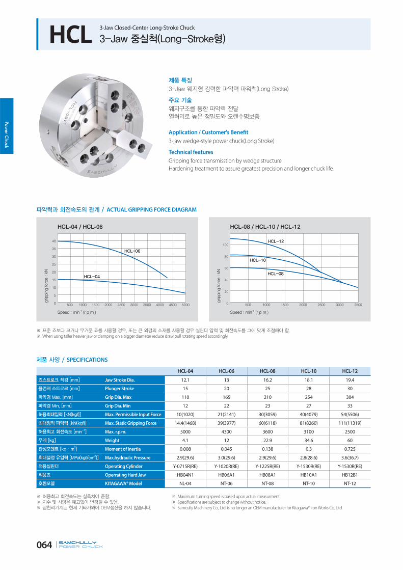
HCL 3-Jaw Closed-Center Long-Stroke Chuck
ACTUAL GRIPPING FORCE DIAGRAM
SPECIFICATIONS
HCL-04 HCL-06 HCL-08 HCL-10 HCL-12
Jaw Stroke Dia. 12.1 13 16.2 18.1 19.4
Plunger Stroke 15 20 25 28 30
Grip Dia. Max 110 165 210 254 304
Grip Dia. Min 12 22 23 27 33
Max. Permissible Input Force 10(1020) 21(2141) 30(3059) 40(4079) 54(5506)
Max. Static Gripping Force 14.4(1468) 39(3977) 60(6118) 81(8260) 111(11319)
Max. r.p.m. 5000 4300 3600 3100 2500
Weight 4.1 12 22.9 34.6 60
Moment of inertia 0.008 0.045 0.138 0.3 0.725
Max.hydraulic Pressure 2.9(29.6) 3.0(29.6) 2.9(29.6) 2.8(28.6) 3.6(36.7)
Operating Cylinder Y-0715R(RE) Y-1020R(RE) Y-1225R(RE) Y-1530R(RE) Y-1530R(RE)
Operrating Hard Jaw HB04N1 HB06A1 HB08A1 HB10A1 HB12B1
KITAGAWA® Model NL-04 NT-06 NT-08 NT-10 NT-12
Maximum turning speed is based upon actual measurment.
Specifications are subject to change without notice.
Samcully Machinery Co., Ltd. is no longer an OEM manufacturer for Kitagawa® Iron Works Co., Ltd.
Application / Customer's Benefit
3-jaw wedge-style power chuck(Long Stroke)
Technical features
Gripping force transmisstion by wedge structure
Hardening treatment to assure greatest precision and longer chuck life
When using taller heavier jaw or clamping on a bigger diameter reduce draw pull rotating speed accordingly.

SAMCHULLYPOWER Chuck 065
Pow
er C
huck
DIMENSIONS
It is recommended to grease chucks at least twice a day in order to maximize longevity.
HCL-04 HCL-06 HCL-08 HCL-10 HCL-12
ΦA 110 165 210 254 304
B 52 74 85 89 106
ΦC(H6) 60 140 170 220 220
F 6 5 5 5 6
ΦH 80 104.8 133.4 171.4 171.4
K 3-M8 6-M10 6-M12 6-M16 6-M16
L 12 14 20 18 18
M 14 20 25 30 30
N max. 26.5 40.5 48.1 54.4 65.7
N min. 20.45 34 40 43.35 56
O max. 9.75 13.75 20.75 29.5 42.75
O min. 6.75 9.25 11.75 11.5 12.75
P max. 18 101.5 131 161 163
P min. 3 81.5 106 133 133
Q 23 31 35 40 50
R 10 12 14 16 18
S 25 36 36 36 46
T M10x1.5 M16x2.0 M20x2.5 M20x2.5 M20x2.5
U 3 4 5 5 5
ΦV 26 34 38 45 50
W 27 35 42 46 54
X 55 72 95 110 129
RELATED PRODUCT
176p 170p 92p
Adaptor H/S Jaw Cylinder

SAMCHULLYPOWER Chuck 066
Power C
huck
HCLT / HCLF 2-Jaw,4Jaw Closed-Center Long-Stroke Chuck
ACTUAL GRIPPING FORCE DIAGRAM
SPECIFICATIONS
Maximum turning speed is based upon actual measurment.
Specifications are subject to change without notice.
Samcully Machinery Co., Ltd. is no longer an OEM manufacturer for Kitagawa® Iron Works Co., Ltd.
HCLT-06 HCLT-08 HCLT-10 HCLT-12 HCLF-08 HCLF-12
Jaw Stroke Dia. 13 16.2 18.1 19.4 16.2 19.4
Plunger Stroke 20 25 28 30 25 30
Grip Dia. Max 165 210 254 304 210 304
Grip Dia. Min 22 24 27 33 24 33
Max. Permissible Input Force 14(1428) 20(2039) 27(2753) 36(3671) 20(2039) 36(3671)
Max. Static Gripping Force 26(2651) 40(4079) 54(5508) 74(7546) 40(4079) 74(7546)
Max. r.p.m. 4300 4300 3100 2500 3600 2500
Weight 12.5 12.5 35.5 60.5 24 60.5
Moment of inertia 0.043 0.133 0.293 0.71 0.132 0.71
Max.Hydraulic Pressure 2.06(21.0) 2.03(20.7) 1.93(19.7) 2.50(25.5) 2.03(20.7) 2.50(25.5)
Operating Cylinder Y-1020R Y-1225R Y-1530R Y-1530R Y-1225R Y-1530R
KITAGAWA® Model NLT-06 NLT-08 NLT-10 NLT-12 NLT-08 NLT-12
Application / Customer's Benefit
2-jaw, 4-jaw wedge-style power chuck
Technical features
Gripping force transmisstion by wedge structure
Hardening treatment to assure greatest precision and longer chuck life
When using taller heavier jaw or clamping on a bigger diameter reduce draw pull rotating speed accordingly.

SAMCHULLYPOWER Chuck 067
Pow
er C
huck
Blank and machined draw-nuts are available. ‘K’ is Max. Draw nut size.
DIMENSIONS
It is recommended to grease chucks at least twice a day in order to maximize longevity.
HCLT-06 HCLT-08 HCLT-10 HCLT-12 HCLF-08 HCLF-12
ΦA 165 210 253 304 210 304
B 74 85 89 106 85 106
ΦC(H6) 140 170 220 220 170 220
F 5 5 5 6 5 6
ΦH 104.8 133.4 171.4 171.4 133.4 171.45
K 6-M10x70 6-M12x85 6-M16x105 6-M16x120 4-M16x85 4-M16x120
L 14 20 38 38 20 38
M 20 25 30 30 25 30
N max. 40.5 48.1 54.4 65.7 48.1 65.7
N min. 34 40 45.35 56 40 56
O max. 13.75 21 29.5 42.75 21 42.75
O min. 9.25 12 11.5 12.25 12 12.25
P max. 101.5 131 161 163 131 163
P min. 81.5 106 133 133 106 133
Q 31 35 40 50 35 50
R 12 14 16 18 14 18
S 36 36 36 36 36 36
T M16x2.0 M20x2.5 M20x2.5 M20x2.5 M20x2.5 M20x2.5
U 4 5 5 5 5 5
ΦV 34 38 45 50 38 50
W 35 42 46 54 42 54
X 72 95 110 129 95 129
RELATED PRODUCT
176p 170p 92p
Adaptor H/S Jaw Cylinder

SAMCHULLYPOWER Chuck 068
Power C
huck
HCWF 4-Jaw Double Wedge Power Chuck
ACTUAL GRIPPING FORCE DIAGRAM
SPECIFICATIONS
HCWF-55
2 Step Manual Jaw Function
Manual Setting (Radial Chuck Jaw) 40+(24)
Manual Jaw Stroke Dia. 60
Plunger Stroke 60
Grip Dia. Max 1400
Grip Dia. Min -
Max. Pemissible Input Force 120 (W1,W2)
Max.Static Gripping Force 210 (J1,J2)
Max. r.p.m. 400
Weight 1400
Moment of inertia 9.05
Operating Cylinder DYV-21560
Application / Customer's Benefit
For clamping round, cubic, pipe and geometrically irregular workpieces
Available with manual jaws
Technical features
Concentric and compensating clamping by double wedge
Hardening treatment to assure greatest precision and longer chuck life
When using taller heavier jaw or clamping on a bigger diameter reduce draw pull rotating speed accordingly.

SAMCHULLYPOWER Chuck 069
Pow
er C
huck
DIMENSIONS
It is recommended to grease chucks at least twice a day in order to maximize longevity.
HCWF-55
ΦA 1400 L1max. 65
ΦB 720 L1min. 5
ΦC 647.6 L2max. 137
ΦC1 1110 L2min. 77
D 26 M 76.2
E 40 N 270
F M30x180 O Max. 716
F1 M24x170 P 85
G M30x80 Q 11
G1 M62x2.0 R 19.025
H 240 S 38.1
Kmax. 250 ΦT 110
Kmin. 226 U 343
V 104
RELATED PRODUCT
94p
Cylinder

ROTARY CYLINDER
삼천리기계는 터닝센터 그리고 머시닝센터에서의 다양하고 광범위한
머신툴 토탈 솔루션을 제공하는 글로벌 기업입니다.
제조산업의 생산성 향상과 고정밀 가공을 위한 끊임없는 신제품 개발과 기술혁신이야 말로
삼천리기계가 지향하는 미래 가치입니다.
Samchully is the global machine tool's total company which has been supplied various
and wide range of solutions for turning and machining center.we are aiming for the
improvement of productivity and high precision machining to manufacturing industry
through awesome products and technology innovation.
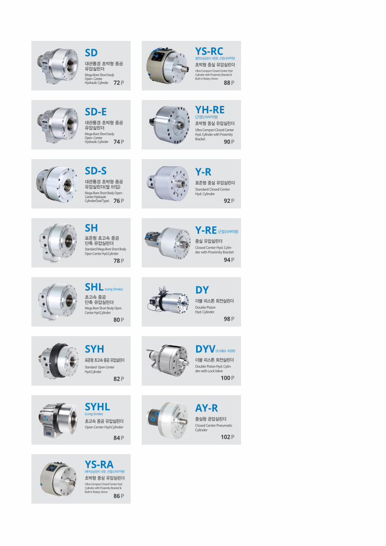
SD
Mega-Bore Short bodyOpen- CenterHydraulic Cylinder 72P
YH-RE
Ultra Compact Closed Center Hyd. Cylinder with Proximity Bracket 90P
SD-E
Mega-Bore Short bodyOpen- CenterHydraulic Cylinder 74P
SD-S
Mega-Bore Short Body Open- Center HydraulicCylinder(Seal Type) 76P
SH
SHL
SYH
Standard Mega Bore Short Body Open Center Hyd.Cylinder
Mega Bore Short Body Open Center Hyd.Cylinder
Standard Open CenterHyd.Cylinder
78P
80P
82P
(Long Stroke)
YS-RA
86P
Ultra Compact Closed Center Hyd.
Cylinder with Proximity Bracket &
Built in Rotary Union
YS-RC
88P
Ultra Compact Closed Center Hyd.
Cylinder with Proximity Bracket &
Built in Rotary Union
Y-R
Y-RE
Standard Closed Center Hyd. Cylinder
Closed Center Hyd. Cylin-der with Proximity Bracket
92P
94P
SYHL
Open Center Hyd.Cylinder
84P
(Long Stroke)
DYDouble PistonHyd. Cylinder
Double Piston Hyd. Cylin-der with Lock Valve
98P
DYV
100P
102P
AY-RClosed Center Pneumatic Cylinder
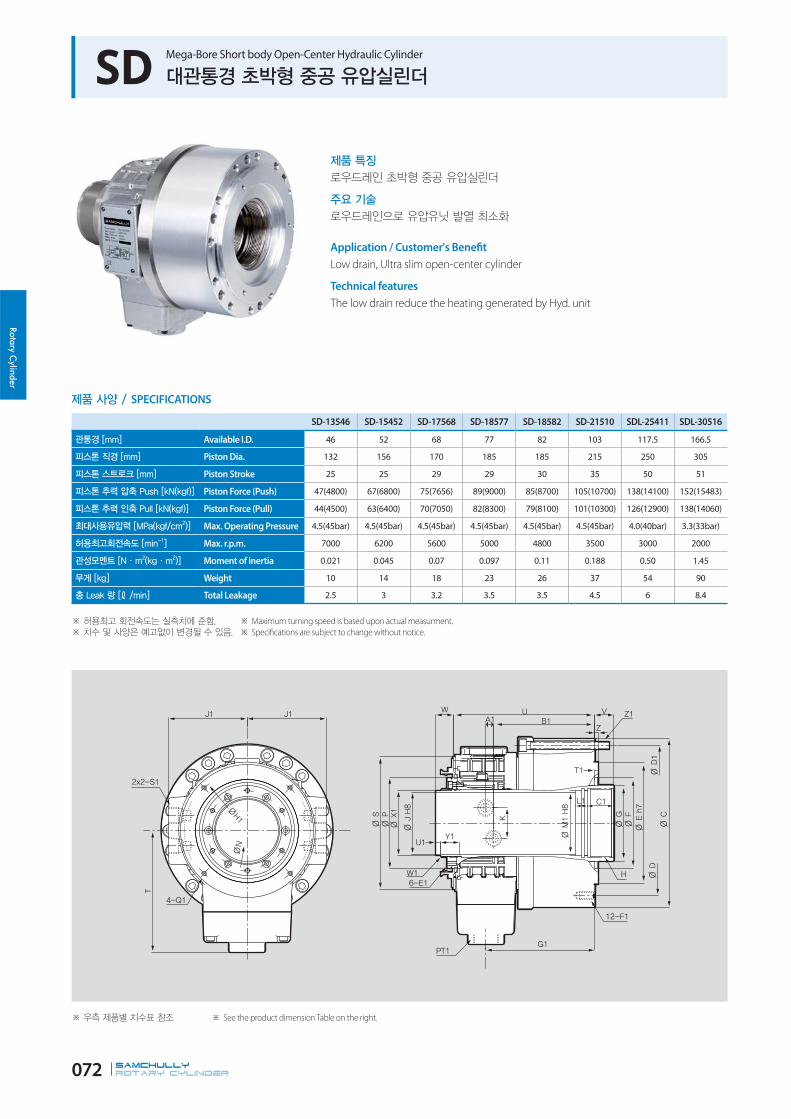
Rotary Cylinder
SAMCHULLYROTARY CYLINDER 072
SD Mega-Bore Short body Open-Center Hydraulic Cylinder
Application / Customer's Benefit
Low drain, Ultra slim open-center cylinder
Technical features
The low drain reduce the heating generated by Hyd. unit
SD-13546 SD-15452 SD-17568 SD-18577 SD-18582 SD-21510 SDL-25411 SDL-30516
Available I.D. 46 52 68 77 82 103 117.5 166.5
Piston Dia. 132 156 170 185 185 215 250 305
Piston Stroke 25 25 29 29 30 35 50 51
Piston Force (Push) 47(4800) 67(6800) 75(7656) 89(9000) 85(8700) 105(10700) 138(14100) 152(15483)
Piston Force (Pull) 44(4500) 63(6400) 70(7050) 82(8300) 79(8100) 101(10300) 126(12900) 138(14060)
Max. Operating Pressure 4.5(45bar) 4.5(45bar) 4.5(45bar) 4.5(45bar) 4.5(45bar) 4.5(45bar) 4.0(40bar) 3.3(33bar)
Max. r.p.m. 7000 6200 5600 5000 4800 3500 3000 2000
Moment of inertia 0.021 0.045 0.07 0.097 0.11 0.188 0.50 1.45
Weight 10 14 18 23 26 37 54 90
Total Leakage 2.5 3 3.2 3.5 3.5 4.5 6 8.4
SPECIFICATIONS
Maximum turning speed is based upon actual measurment.
Specifications are subject to change without notice.
See the product dimension Table on the right.

Rota
ry C
ylin
der
SAMCHULLYROTARY CYLINDER 073
SD-13546 SD-15452 SD-17568 SD-18577 SD-18582 SD-21510 SDL-25411 SDL-30516
ΦC 165 190 210 218 223 266 310 370
ΦD 130 170 190 190 190 225 275 290
ΦD1 147 170 190 200 205 240 275 345
ΦE 100 130 160 160 160 200 230 260
ΦF 80 85 120 120 120 160 166 240
ΦG 65 70 85 95 100 125 140 190
H M52x2.0p M60x2.0p M75x2.0p M85x2.0p M90x2.0p M112x2.0p M130x2.0p M180x3.0p
ΦJ 46.5 52 68 77 82 103 117.5 166.5
K 36 36 40 40 40 48 46 42
N 63 76 92 102 106 128 138 188
ΦP 78.8 89.8 105.8 115.8 119.8 157.8 170 222
ΦS 116 135 154 164 175 205 230 278
T 119 134 141 149.5 160.5 174.5 204 230
U 159 150.5 172.5 182 186.5 203 258 290
V max 15 22 25 25 25 35 46 51
V min -10 -3 -4 -4 -5 0 -4 0
W max 55 50 59 56 53 60 75 76
W min 30 25 30 27 23 25 25 25
Z 5 5 5 8 5 5 6 5
A1 8.5 8.5 11 11 11 14 18 17.5
B1 117.5 107.5 122.5 129.5 133 140 178.5 206
C1 30 30 30 35 35 30 45 45
E1 M6 M6 M6 M6 M6 M6 M6 M6
F1DP' M10x20 M10x20 M10x20 M10x20 M10x20 M12x20 M16x32 M16x32
G1 125.5 115.5 132.5 139.5 143.5 152.5 194.5 221
H1 105 118 145 155 160 190 206 256
J1 75 80 90 95 104 120 135 160
K1 47 47 47 47 47 47 47 47
L1 15 15 21 15 15 15 20 20
M1 48 55 71 80 85 106 123 170
Q1 M5x10 M6x10 M6x10 M6x10 M6x12 M6x12 M6x12 M6x12
S1 PT1/2 PT1/2 PT1/2 PT1/2 PT1/2 PT1/2 PT1/2 PT1/2
T1 7 7 8 8 8 6 6 7
W1 M52x1.5p M58x1.5p M74x1.5p M84x2.0p M89x2.0p M119x2.0p M124x2.0p M180x3.0p
ΦX1 50 56 71.5 81 86 116 121.5 170.5
Y1 24 20 28 26 25 38 29 45
U1 9 9 8 9 6 9 9 8
Z1 6-M8x90 6-M8x90 6-M10x95 8-M8x110 6-M10x110 6-M12x120 8-M12x140 6-M10x95
DIMENSIONS

Rotary Cylinder
SAMCHULLYROTARY CYLINDER 074
SD-E Mega-Bore Short body Open-Center Hydraulic Cylinder(Europe type)
Application / Customer's Benefit
Low drain, Ultra slim open-center cylinder
Technical features
The low drain reduce the heating generated by Hyd. unit
SD-13546E SD-15452E SD-16567E SD-17577E SD-18582E SD-19586E SD-20595E SD-21511E
Available I.D. 46.5 52.5 67.5 77 82 86.5 95.5 110.5
Piston Dia. 132 151 165 177 185 190 205 220
Piston Stroke 25 25 29 29 30 34 34 35
Piston Force (Push) 47(4800) 62(6285) 67(6863) 80(8100) 85(8700) 90(9200) 105(10700) 115(11700)
Piston Force (Pull) 44(4500) 57(5850) 62(6351) 73(7400) 79(8100) 83(8500) 95(9700) 107(10900)
Max. Operating Pressure 4.5(45) 4.5(45) 4.5(45) 4.5(45) 4.5(45) 4.5(45) 4.5(45) 4.5(45)
Max. r.p.m. 7000 6200 5600 5000 4800 4500 4000 3600
Moment of inertia 0.03 0.045 0.07 0.097 0.11 0.13 0.17 0.28
Weight 11 14 18 23 26 27 29 40
Total Leakage 2.5 3 3.2 3.5 3.5 4 5 7
SPECIFICATIONS
Maximum turning speed is based upon actual measurment.
Specifications are subject to change without notice.
See the product dimension Table on the right.

Rota
ry C
ylin
der
SAMCHULLYROTARY CYLINDER 075
SD-13546E SD-15452E SD-16567E SD-17577E SD-18582E SD-19586E SD-20595E SD-21511E
ΦC 162 182 197 214 223 228 245 266
ΦD 130 165 180 195 205 210 227 240
ΦD1 147 165 180 195 205 210 227 240
ΦE 130 140 160 160 168 180 210 210
ΦF 76 85 120 120 120 120 130 160
ΦG 61 70 85 95 100 105 115 130
H M55x2.0p M60x2.0p M75x2.0p M85x2.0p M90x2.0p M112x2.0p M105x2.0p M120x2.0p
H1 M50X1.5p M55x2.0p M72x1.5p M80x2.0p M90x2.0p M100x2.0p M115x2.0p
ΦJ 46.5 52.5 67.5 77 82 86.5 95.5 110.5
K 36 36 40 40 40 40 40 48
N 64 76 92 102 106 112 124 139
ΦP 78.8 89.8 105.8 115.8 119.8 125.8 137.8 160
ΦS 116 135 154 164 175 181 188 208
T 119 134 141 149.5 159.5 158.5 166 174.5
U 149 148 172.5 172.5 186.5 191 200 233.5
V max 22 22 25 25 23 31 31 31
V min -3 -3 -4 -4 -7 -3 -3 -4
W max 42 45.5 51.5 51.5 53 58 59 63
W min 17 20.5 22.5 22.5 23 24 25 28
Z 5 5 8 8 5 8 8 8
A1 8.5 8.5 11 11 11 13 13 14
B1 107.5 107.5 122.5 122.5 133 136 143 170.5
C1 25 25 25 25 35 32 32 32
C2 25 28 28 28 30 30 30
E1 M6 M6 M6 M6 M6 M6 M6 M6
F1DP' M10 DP'20 M10 DP'20 M10 DP'20 M10 DP'20 M10 DP'20 M10 DP'20 M10 DP'20 M12 DP'24
G1 115.5 115.5 132.5 132.5 143.5 144 151 180
J1 75 80 90 95 104 108 116 120
K1 47 47 47 47 47 47 47 47
L1 6 6 6 6 15 6 6 6
L2 6 6 6 6 6 6 6
M1 52.5 57 72.5 82 85 92 102.5 117.5
M2 47 52.5 69 77 87 97 112
Q 105 118 145 155 160 168 168 190
Q1 M5DP'10 M6DP'10 M6DP'10 M6DP'10 M6DP'12 M6DP'12 M6DP'12 M6DP'12
S1 G3/8 G3/8 G3/8 G3/8 G3/8 G3/8 G3/8 G3/8
T1 7 7 8 8 8 9 9 9
W1 M52x1.5p M60x1.5p M74x1.5p M84x2.0p M89x2.0p M94x2.0p M104x2.0p M120x2.0p
ΦX1 50 58 71 81 86 91 101 117
Y1 24 21 24 25 25 26 26 34
U1 6 5 5 5 6 5 6 6
Z1 6-M8x90 6-M8x90 6-M10x100 6-M10x100 6-M10x110 6-M10x105 6-M10x110 6-M10x135
DIMENSIONS

Rotary Cylinder
SAMCHULLYROTARY CYLINDER 076
Application / Customer's Benefit
Low drain, Ultra slim open-center cylinder
Technical features
Low drain minimizeds heat
Prohibit leakage of cylinder by sealed function
Ideal for small space of machine and installation into sub spindle.
SD-13546S SD-18546S SD-17568S
Available I.D. 46 46 68
Piston Dia. 132 170 170
Piston Stroke 25 30 29
Piston Force (Push) 47(4800) 85(8700) 75(7656)
Piston Force (Pull) 44(4500) 80(8200) 70(7050)
Max. Operating Pressure 4.5 MPA (45 bar) 4.5 MPA (45 bar) 4.5 MPA (45 bar)
Max. r.p.m. 6000 4800 4800
Moment of inertia 0.021 0.11 0.07
Weight 9 20 18
Total Leakage 2.5 3 3.2
SPECIFICATIONS
Maximum turning speed is based upon actual measurment.
Specifications are subject to change without notice.
See the product dimension Table on the right.
SD-S Mega-Bore Short Body Open-Center Hydraulic Cylinder(Seal Type)
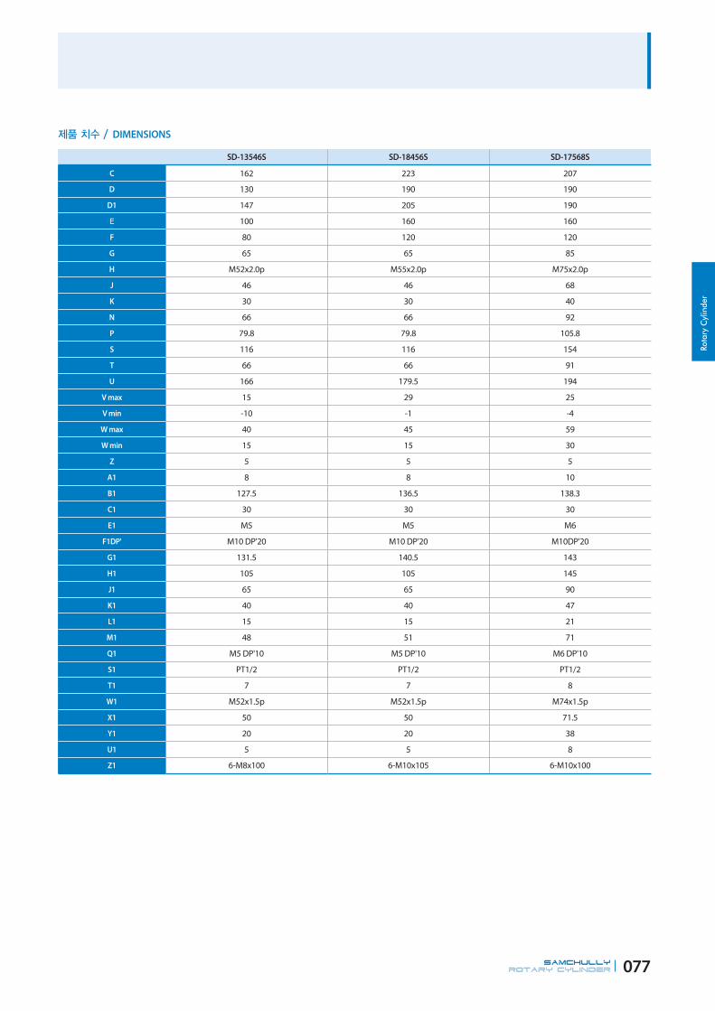
Rota
ry C
ylin
der
SAMCHULLYROTARY CYLINDER 077
SD-13546S SD-18456S SD-17568S
C 162 223 207
D 130 190 190
D1 147 205 190
100 160 160
F 80 120 120
G 65 65 85
H M52x2.0p M55x2.0p M75x2.0p
J 46 46 68
K 30 30 40
N 66 66 92
P 79.8 79.8 105.8
S 116 116 154
T 66 66 91
U 166 179.5 194
V max 15 29 25
V min -10 -1 -4
W max 40 45 59
W min 15 15 30
Z 5 5 5
A1 8 8 10
B1 127.5 136.5 138.3
C1 30 30 30
E1 M5 M5 M6
F1DP' M10 DP'20 M10 DP'20 M10DP'20
G1 131.5 140.5 143
H1 105 105 145
J1 65 65 90
K1 40 40 47
L1 15 15 21
M1 48 51 71
Q1 M5 DP'10 M5 DP'10 M6 DP'10
S1 PT1/2 PT1/2 PT1/2
T1 7 7 8
W1 M52x1.5p M52x1.5p M74x1.5p
X1 50 50 71.5
Y1 20 20 38
U1 5 5 8
Z1 6-M8x100 6-M10x105 6-M10x100
DIMENSIONS

Rotary Cylinder
SAMCHULLYROTARY CYLINDER 078
SH Standard Mega-Bore Short-Body Open-Center Hydraulic Cylinder
Application / Customer's Benefit
A high speed, open-center cylinder with a larger bore and ligther than the
standard SYH
Technical features
Built-in lock and relief valves prevent damage caused by excessive pressure, and
ensures saftey during blackouts or loss of power by maintaining pull force
SH-10036 SH-13046 SH-15052 SH-17068 SH-18077 SH-19082 SH-21010 SH-25011
Available I.D. 36 46 52 68 77 82 106 117.5
Piston Dia. 105 135 156 170 185 190 215 255
Piston Stroke 12 15 22 25 25 25 30 23
Piston Force (Push) 25(2549) 42.3(4285) 60(6118) 63(6531) 75.3(7632) 78.1(7924) 91.8(9357) 132(13390)
Piston Force (Pull) 24(2447) 38.1(3865) 56(5710) 59.8(6060) 69.6(7087) 72.5(7350) 87.8(8952) 121(12305)
Max. Operating Pressure 4.0(40.8) 4.0(40.8) 4.0(40.8) 4.0(40.8) 4.0(40.8) 4.0(40.8) 4.0(40.8) 4.0(40.8)
Max. r.p.m. 8000 7000 6200 5600 5000 4800 3500 3000
Moment of inertia 0.43(0.044) 0.2(0.021) 0.44(0.045) 0.65(0.067) 0.83(0.084) 0.95(0.097) 1.84(0.188) 1.9(0.193)
Weight 8.4 10 14 16.5 18 25 37 50
Total Leakage 3.0 3.0 3.9 4.0 4.2 4.5 6.0 7.0
SPECIFICATIONS
Maximum turning speed is based upon actual measurment.
Specifications are subject to change without notice.
See the product dimension Table on the right.

Rota
ry C
ylin
der
SAMCHULLYROTARY CYLINDER 079
SH-10036 SH-13046 SH-15052 SH-17068 SH-18077 SH-19082 SH-21010 SH-25011
ΦC 135 165 190 210 218 223 263 310
ΦD 115 130 170 190 190 190 225 275
ΦE 100 100 130 160 160 160 200 230
ΦF 65 80 85 120 120 120 160 166
ΦG 48 65 70 85 95 100 125 140
Hmax. M42x1.5 M52x2.0 M60x2.0 M75x2.0 M85x2.0 M90x2.0 M115x2.0 M130x2.0
ΦJ 36 46 52 68 77 82 106 117.5
K 30 40 40 48 48 58 48 46
N 55 64 73 88 98 103 142 138
ΦP 73 85 96 111 121 126 157.8 170
ΦS 104 116 135 154 164 175 205 230
T 115 120 130 150 165 166 195 107.5
U 130 142 136 155 167 174 199.7 231
V max. 15 15 22 25 25 25 30 18
V min. 3 0 0 0 0 0 0 -5
W max. 37 40 47 50 50 44 55 48
W min. 25 25 25 25 25 19 25 25
Z 5 5 5 5 5 5 5 6
A1 9 8.5 9 10 10 11.5 14 19
B1 90 103 97.5 108 119.5 122 136.5 150
C1 25 30 30 35 35 35 35 45
E1 M5 M6 M6 M6 M6 M6 M6 M6
F1DP' M10x17 M10x20 M10x20 M10x20 M10x20 M12x20 M12x20 M16x32
G1 93.5 111 101 113 125 129.5 151 163.5
H1 96 105 118 145 155 160 190 206
J1 73 82 92 97 102 105 120 140
K1 47 47 47 47 47 47 47 55
L1 15 15 15 15 15 15 15 20
ΦM1 38 48 55 71 80 85 110 123
ΦN1 64 76 85 100 108 113 128 150
P1 4 4 4 4 4 4 4 5.5
Q1 M5x7 M5x6 M6x7 M6x10 M6x10 M6x10 M6x10 M6x12
R1 5 6 7 7 7 7 7 7.5
S1 PT 1/2 PT 1/2 PT 1/2 PT 1/2 PT 1/2 PT 1/2 PT 1/2 PT 1/2
T1 6 6 5.5 5 5 6 6 6
W1 M44x1.5 M52x1.5 M58x1.5 M74x1.5 M84x2.0 M89x2.0 M119x2.0 M124x2.0
ΦX1 42 50 56 72.5 81 86 116 122
Y1 30 24 20 26 26 26 38 29
DIMENSIONS

Rotary Cylinder
SAMCHULLYROTARY CYLINDER 080
SHL Mega-Bore Short-Body Long-Stroke Open-Center Hydraulic Cylinder
Application / Customer's Benefit
A high speed, open-center cylinder with a larger bore and ligther than the
standard SYH(Long Stroke)
Technical features
Built-in lock and relief valves prevent damage caused by excessive pressure, and
ensures saftey during blackouts or loss of power by maintaining pull force
SHL-17068 SHL-18077 SHL-25011 SHL-39024
Available I.D. 68 77 117.5 240
Piston Dia. 170 185 255 390
Piston Stroke 40 40 50 51
Piston Force (Push) 63(6531) 75.3(7632) 132(13390) 152.5(15570)
Piston Force (Pull) 59.8(6060) 69.6(7087) 121(12305) 138.7(14152)
Max. Operating Pressure 4.0(40.8) 4.0(40.8) 4.0(40.8) 2.5(25)
Max. r.p.m. 5600 5000 3000 1500
Moment of inertia 0.69(0.070) 0.86(0.088) 1.9(0.193) 39.64(4.045)
Weight 17.8 18.5 54 140
Total Leakage 4 4.2 7 14
SPECIFICATIONS
Maximum turning speed is based upon actual measurment.
Specifications are subject to change without notice.
See the product dimension Table on the right.
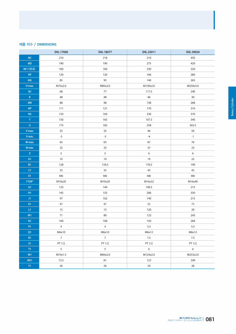
Rota
ry C
ylin
der
SAMCHULLYROTARY CYLINDER 081
DIMENSIONS
SHL-17068 SHL-18077 SHL-25011 SHL-39024
ΦC 210 218 310 450
ΦD 190 190 275 420
ΦE 160 160 230 320
ΦF 120 120 166 280
ΦG 85 95 140 265
H max. M75x2.0 M85x2.0 M130x2.0 M250x3.0
ΦJ 68 77 117.5 240
K 48 48 46 30
ΦN 88 98 138 268
ΦP 111 121 170 310
ΦS 154 164 230 370
T 150 165 107.5 340
U 175 182 258 302.5
V max. 35 35 46 50
V min. -5 -5 -4 -1
W max. 65 65 87 76
W min. 25 25 37 25
Z 5 5 6 6
A1 10 10 19 22
B1 128 134.5 176.5 199
C1 35 35 45 45
E1 M6 M6 M6 M6
F1DP' M10x20 M10x20 M16x32 M16x40
G1 133 140 190.5 215
H1 145 155 206 350
J1 97 102 140 215
K1 47 47 55 75
L1 15 15 120 20
M1 71 80 123 243
N1 100 108 150 284
P1 4 4 5.5 5.5
Q1 M6x10 M6x10 M6x12 M6x12
R1 7 7 7.5 7.5
S1 PT 1/2 PT 1/2 PT 1/2 PT 1/2
T1 5 5 6 6
W1 M74x1.5 M84x2.0 M124x2.0 M253x2.0
ΦX1 72.5 81 122 249
Y1 26 26 29 38

Rotary Cylinder
SAMCHULLYROTARY CYLINDER 082
SYH Standard Open-Center Hydraulic Cylinder
Application / Customer's Benefit
Compact and light weight
Technical features
Built-in lock and relief valves prevent damage caused by excessive pressure, and
ensures saftey during blackouts or loss of power by maintaining pull force
SYH-1036 SYH-1246 SYH-1552 SYH-1877 SYH-2091
Available I.D. 36 36,39,40,41,43,45,46 46,52,69 68,69,75,77 78,91
Piston Dia. 105 125 155 180 205
Piston Stroke 15 15 22 25 30
Piston Surface Area (Push) 67 100 161 198 252
Piston Surface Area (Pull) 64.5 89 150 183 234
Piston Force (Push) 25(2549) 38(3875) 60(6118) 74(7546) 94(9584)
Piston Force (Pull) 24(2447) 33(3365) 56(5710) 69(7036) 88(8973)
Max. Operating Pressure 4.0(40.8) 4.0(40.8) 4.0(40.8) 4.0(40.8) 4.0(40.8)
Max. r.p.m. 8000 8000 6200 4700 3800
Moment of inertia 0.10(0.011) 0.18(0.019) 0.52(0.053) 0.93(0.095) 1.45(0.153)
Weight 8.6 12 16.8 26 33
Total leakage 3 3 3.9 4.2 4.5
KITAGAWA® Model S-1036 S-1246 S-1552 S-1875 S-2091
SPECIFICATIONS
Maximum turning speed is based upon actual measurment.
Specifications are subject to change without notice.
See the product dimension Table on the right.

Rota
ry C
ylin
der
SAMCHULLYROTARY CYLINDER 083
SYH-1036 SYH-1246 SYH-1552 SYH-1877 SYH-2091
ΦC 135 155 190 215 240
ΦD 115 130 170 190 215
ΦE 100 100 130 160 180
ΦF 65 80 85 120 140
ΦG 48 65 70 95 110
H max. M42x1.5 M52x2.0 M60x2.0 M85x2.0 M100x2.0
ΦJ 36 46 52 77 91
K 30 36 36 36 34
ΦM 44.6 52.9 59.6 84.6 99.6
ΦN 55 64 73 98 108
ΦP 73 85 96 121 138
ΦQ 45 51.5 57 70 79
ΦS 104 118 137 166 182
T 115 115 130 160 185
U 156 184 191 230 253
V max. 15 15 22 25 30
V min. 0 0 0 0 0
W max. 40 40 47 50 55
W min. 25 25 25 25 25
Z 5 5 5 5 5
A1 11 11.5 12 17.5 21
B1 102.5 126.5 136 153.5 168
C1 25 30 30 35 35
E1 M5x11 M6x9 M6x9 M6x9 M6x14
F1 6-M10x17 12-M10x20 12-M10x20 12-M10x20 12-M12x24
G1 98 135 145 166.5 183
H1 88 98 110 155 165
J1 73 76 86 101 110
K1 47 47 47 47 47
L1 15 15 15 15 15
M1 38 48 55 80 95
ΦN1 64 76 85 108 120
P1 4 4 4 4 4
Q1 M5x10 M5x10 M6x12 M6x12 M6x12
R1 5 6 7 7 7
S1 PT3/8 PT1/2 PT1/2 PT1/2 PT1/2
T1 6 6 6 6 6
ΦU1 158 200 220 242 267
V1 28 46 51 58 66
W1 M44x1.5 M52x1.5 M58x1.5 M84x2.0 M99x2.0
ΦX1 42 50 56 81 96
DIMENSIONS

Rotary Cylinder
SAMCHULLYROTARY CYLINDER 084
SYHL Standard Open-Center Long-Stroke Hydraulic Cylinder
SYHL-1246 SYHL-1552 SYHL-1877 SYHL-2091 SYHL-2816
Available I.D. 46 52 68,75,77 91 166.5
Piston Dia. 125 155 180 205 280
Piston Stroke 32 34 40 50 51
Piston Surface Area (Push) 100 161 198 252 377
Piston Surface Area (Pull) 89 150 183 234 332
Piston Force (Push) 38(3875) 60(6118) 74(7546) 94(9585) 113(11522)
Piston Force (Pull) 33(3365) 56(5710) 69(7063) 88(8973) 100(10196)
Max. Operating Pressure 4.0(40.8) 4.0(40.8) 4.0(40.8) 4.0(40.8) 3.3(33.6)
Max. r.p.m. 7000 6200 4700 3800 2000
Moment of inertia 0.21(0.022) 0.56(0.058) 0.10(0.098) 1.56(0.160) 35.5(3.31)
Weight 12.8 17 26.8 34.1 101
Total leakage 3 3.9 4.2 4.5 8.4
KITAGAWA® Model S-1246L S-1552L S-1875L S-2091L S-2816L
SPECIFICATIONS
Maximum turning speed is based upon actual measurment.
Specifications are subject to change without notice.
Certain models have several thru-hole size available.
The bore threading varies by model. H max represents the largest possible threading.
See the product dimension Table on the right.
Application / Customer's Benefit
Compact and lightweight(Long Stroke)
Technical features
Built-in lock and relief valves prevent damage caused by excessive pressure, and
ensures saftey during blackouts or loss of power by maintaining pull force
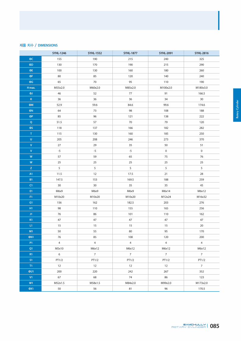
Rota
ry C
ylin
der
SAMCHULLYROTARY CYLINDER 085
SYHL-1246 SYHL-1552 SYHL-1877 SYHL-2091 SYHL-2816
ΦC 155 190 215 240 325
ΦD 130 170 190 215 290
ΦE 100 130 160 180 260
ΦF 80 85 120 140 240
ΦG 65 70 95 110 190
H max. M55x2.0 M60x2.0 M85x2.0 M100x2.0 M180x3.0
ΦJ 46 52 77 91 166.5
K 36 36 36 34 30
ΦM 52.9 59.6 84.6 99.6 174.6
ΦN 64 73 98 108 188
ΦP 85 96 121 138 222
Q 51.5 57 70 79 120
ΦS 118 137 166 182 282
T 115 130 160 185 250
U 205 208 246 273 370
V 27 29 35 50 51
V -5 -5 -5 0 0
W 57 59 65 75 76
W 25 25 25 25 25
Z 5 5 5 5 5
A1 11.5 12 17.5 21 28
B1 147.5 153 169.5 188 259
C1 30 30 35 35 45
E1 M6x9 M6x9 M6x9 M6x14 M6x12
F1 M10x20 M10x20 M10x20 M12x24 M16x32
G1 156 162 182.5 203 276
H1 98 110 155 165 256
J1 76 86 101 110 162
K1 47 47 47 47 47
L1 15 15 15 15 20
M1 50 55 80 95 170
ΦN1 76 85 108 120 200
P1 4 4 4 4 4
Q1 M5x10 M6x12 M6x12 M6x12 M6x12
R1 6 7 7 7 7
S1 PT1/2 PT1/2 PT1/2 PT1/2 PT1/2
T1 12 12 12 12 7
ΦU1 200 220 242 267 352
V1 67 68 74 86 123
W1 M52x1.5 M58x1.5 M84x2.0 M99x2.0 M173x2.0
ΦX1 50 56 81 96 170.5
DIMENSIONS

Rotary Cylinder
SAMCHULLYROTARY CYLINDER 086
YS-RA Ultra-Compact Closed-Center Hydraulic Cylinder with Proximity Bracket and Built-in Rotary joint
Application / Customer's Benefit
Ultra-Compact Closed-Center Hydraulic Cylinder with Proximity Bracket
Technical features
Built-in lock and relief valves prevent damage caused by excessive pressure
Ensures saftey during blackouts or loss of power by maintaining pull force
Built-in Rotary joint
SPECIFICATIONS
Maximum turning speed is based upon actual measurment.
Specifications are subject to change without notice.
YS-11020RA YS-12021RA YS-13030RA
Piston Stroke 20 21 30
Piston Surface Area (Push) 87.6 105.7 131.8
Piston Surface Area (Pull) 84 102 122.5
Piston Force (Push) 28(2855) 39(3977) 47(4793)
Piston Force (Pull) 27(2753) 38(3875) 45(4589)
Max. Operating Pressure 3.5(35.7) 4.0(40.8) 4.0(40.8)
Max. r.p.m. 6000 6000 6000
Moment of inertia 0.157(0.016) 0.274(0.028) 0.284(0.029)
Weight 8.2 10.2 10.3
Total leakage 1.2 1.2 1.2
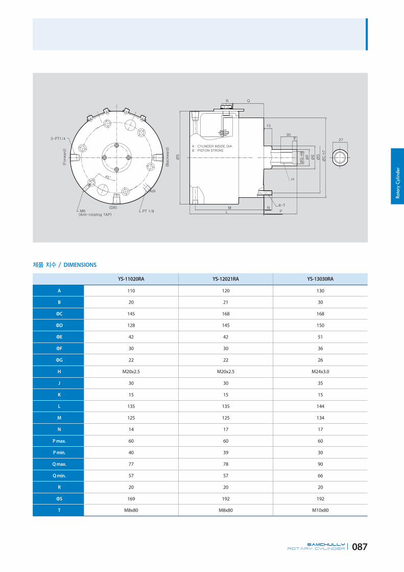
Rota
ry C
ylin
der
SAMCHULLYROTARY CYLINDER 087
YS-11020RA YS-12021RA YS-13030RA
A 110 120 130
B 20 21 30
ΦC 145 168 168
ΦD 128 145 150
ΦE 42 42 51
ΦF 30 30 36
ΦG 22 22 26
H M20x2.5 M20x2.5 M24x3.0
J 30 30 35
K 15 15 15
L 135 135 144
M 125 125 134
N 14 17 17
P max. 60 60 60
P min. 40 39 30
Q max. 77 78 90
Q min. 57 57 66
R 20 20 20
ΦS 169 192 192
T M8x80 M8x80 M10x80
DIMENSIONS

Rotary Cylinder
SAMCHULLYROTARY CYLINDER 088
YS-RC Ultra-compact closed-center hydraulic cylinder with proximity bracket and built-in rotary joint
Application / Customer's Benefit
Ultra-compact closed-center hydraulic cylinder
Technical features
Built-in lock and relief valves prevent damage caused by excessive pressure
Ensures saftey during blackouts or loss of power by maintaining pull force
Built-in Rotary joint
SPECIFICATIONS
Maximum turning speed is based upon actual measurment.
Specifications are subject to change without notice.
YS-11020RC
Piston Stroke 20
Piston Surface Area (Push) 87.6
Piston Surface Area (Pull) 84
Piston Force (Push) 28(2855)
Piston Force (Pull) 27(2753)
Max. Operating Pressure 3.5(35.7)
Max. r.p.m. 6000
Moment of inertia 0.157(0.016)
Weight 9
Total leakage 1.2

Rota
ry C
ylin
der
SAMCHULLYROTARY CYLINDER 089
YS-11020RC
A 110
B 20
ΦC 145
ΦD 128
ΦE 42
ΦF 30
ΦG 22
H M20x2.5
J 30
K 15
L 135
M 125
DIMENSIONS
YS-11020RC
N 15
P max. 60
P min. 40
Q max. 77
Q min. 57
R 20
ΦS 169
T M8x80
U 21
V 40
W 49
X 87

Rotary Cylinder
SAMCHULLYROTARY CYLINDER 090
YH-RE Ultra-Compact Closed-Center Hydraulic Cylinder with Proximity Bracket
Application / Customer's Benefit
Ultra-Compact Closed-Center Hydraulic Cylinder with Proximity Bracket
Technical features
Built-in lock and relief valves prevent damage caused by excessive pressure, and
ensures saftey during blackouts or loss of power by maintaining pull force
SPECIFICATIONS
Maximum turning speed is based upon actual measurment.
Specifications are subject to change without notice.
YH-10120RE YH-10125RE YH-12125RE YH-12140RE YH-15130RE YH-15150RE YH-20135RE YH-20150RE YH-25160RE
Piston Stroke 20 25 25 40 30 50 35 50 60
Piston Surface Area (Push) 78 78 114 114 168 168 305 305 515
Piston Surface Area (Pull) 73 73 106 106 154 154 283 283 482
Piston Force (Push) 29(2960) 29(2960) 42(4326) 42(4326) 63(6375) 63(6375) 114(11573) 114(11573) 193(19541)
Piston Force (Pull) 27(2770) 27(2770) 39(4022) 39(4022) 57(5843) 57(5843) 105(10738) 105(10738) 180(18289)
Max. Operating Pressure 40(40.8) 40(40.8) 40(40.8) 40(40.8) 40(40.8) 40(40.8) 40(40.8) 40(40.8) 40(40.8)
Max. r.p.m. 6000 6000 6000 6000 5500 5500 5500 5500 2000
Moment of inertia 0.49(0.05) 0.49(0.05) 0.88(0.09) 0.88(0.09) 1.86(0.19) 1.96(0.2) 3.82(0.39) 4.12(0.42) 9(0.92)
Weight 7.6 7.7 10.5 11 14 14.5 22.5 23.5 88
Total leakage 0.8 0.8 0.8 0.8 0.8 0.8 0.8 0.8 0.8

Rota
ry C
ylin
der
SAMCHULLYROTARY CYLINDER 091
YH-10120RE YH-10125RE YH-12125RE YH-12140RE YH-15130RE YH-15150RE YH-20135RE YH-20150RE YH-25160RE
ΦC 135 135 160 160 190 190 245 245 305
ΦD 118 118 142 142 170 170 222 222 275
ΦE 80 80 110 110 110 110 120 120 160
ΦF 30 30 35 35 45 45 55 55 65
ΦG 21 21 25 25 31 31 37 37 44
J 35 35 44 44 45 55 60 60 65
K 209.6 214.6 220.6 267.1 228.6 280.1 240.6 280.1 310
L 126.6 126.6 126.6 156.6 126.6 158.1 133.6 158.1 136
M 83 88 94 109 102 122 107 122 142.5
N 116.5 121.5 127.5 142.5 135.5 155.5 140.5 155.5 176
P max. 45 45 51 65 56 80 69 80 85
P min. 25 20 26 25 26 30 34 30 25
Q 6-M10x20 6-M10x20 12-M12x24 12-M12x24 12-M12x24 12-M12x24 12-M16x30 12-M16x30 12-M20x35
R 122.5 127.5 133.5 148.5 141.5 161.5 146.5 161.5 182
S 67 72 72 87 80 100 85 100 120.5
DIMENSIONS
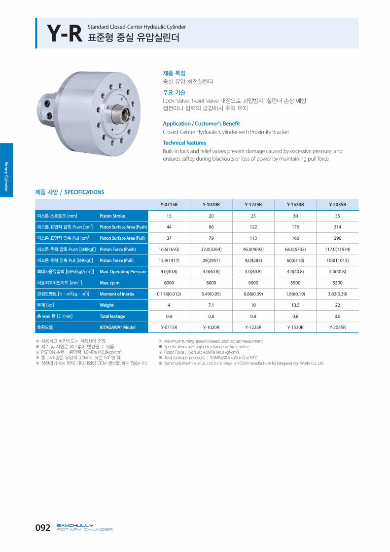
Rotary Cylinder
SAMCHULLYROTARY CYLINDER 092
Y-R Standard Closed-Center Hydraulic Cylinder
Application / Customer's Benefit
Closed-Center Hydraulic Cylinder with Proximity Bracket
Technical features
Built-in lock and relief valves prevent damage caused by excessive pressure, and
ensures saftey during blackouts or loss of power by maintaining pull force
SPECIFICATIONS
Y-0715R Y-1020R Y-1225R Y-1530R Y-2035R
Piston Stroke 15 20 25 30 35
Piston Surface Area (Push) 44 86 122 176 314
Piston Surface Area (Pull) 37 79 113 160 290
Piston Force (Push) 16.6(1693) 32.0(3264) 46.0(4692) 66.0(6732) 117.0(11934)
Piston Force (Pull) 13.9(1417) 29(2957) 42(4283) 60(6118) 108(11013)
Max. Operating Pressure 4.0(40.8) 4.0(40.8) 4.0(40.8) 4.0(40.8) 4.0(40.8)
Max. r.p.m. 6000 6000 6000 5500 5500
Moment of inertia 0.118(0.012) 0.49(0.05) 0.88(0.09) 1.86(0.19) 3.82(0.39)
Weight 4 7.1 10 13.5 22
Total leakage 0.8 0.8 0.8 0.8 0.8
KITAGAWA® Model Y-0715R Y-1020R Y-1225R Y-1530R Y-2035R
Maximum turning speed is based upon actual measurment.
Specifications are subject to change without notice.
Piston Force : Hydraulic 4.0MPa (40.8 kgf/cm2)
3.0MPa(30.6 kgf/cm2) at 50 C
Samchully Machinary Co., Ltd. is no longer an OEM manufacturer for kitagawa Iron Works Co., Ltd

Rota
ry C
ylin
der
SAMCHULLYROTARY CYLINDER 093
2-M5x10
4040
30
30
68
2-M5x10
45
30
Y-0715R Y-1020R Y-1225R Y-1530R Y-2035R
A 75 105 125 150 200
B 15 20 25 30 35
ΦC 104 135 160 190 245
ΦD 90 100 130 130 145
ΦE 65 80 110 110 120
ΦF 30 30 35 45 55
ΦG 21 21 25 31 37
H max. M20x2.5 M20x2.5 M24x3.0 M30x3.5 M36x4.0
J 35 35 44 45 60
K 172 197 205 214 228
L 106 108 108 108 106
M 66 89 97 106 122
N 127 152 160 169 183
P max. 46 45 51 56 69
P min. 31 25 26 26 34
Q 6-M6x20 6-M10x20 6-M12x24 6-M12x24 12-M16x30
R 133 158 166 175 189
DIMENSIONS
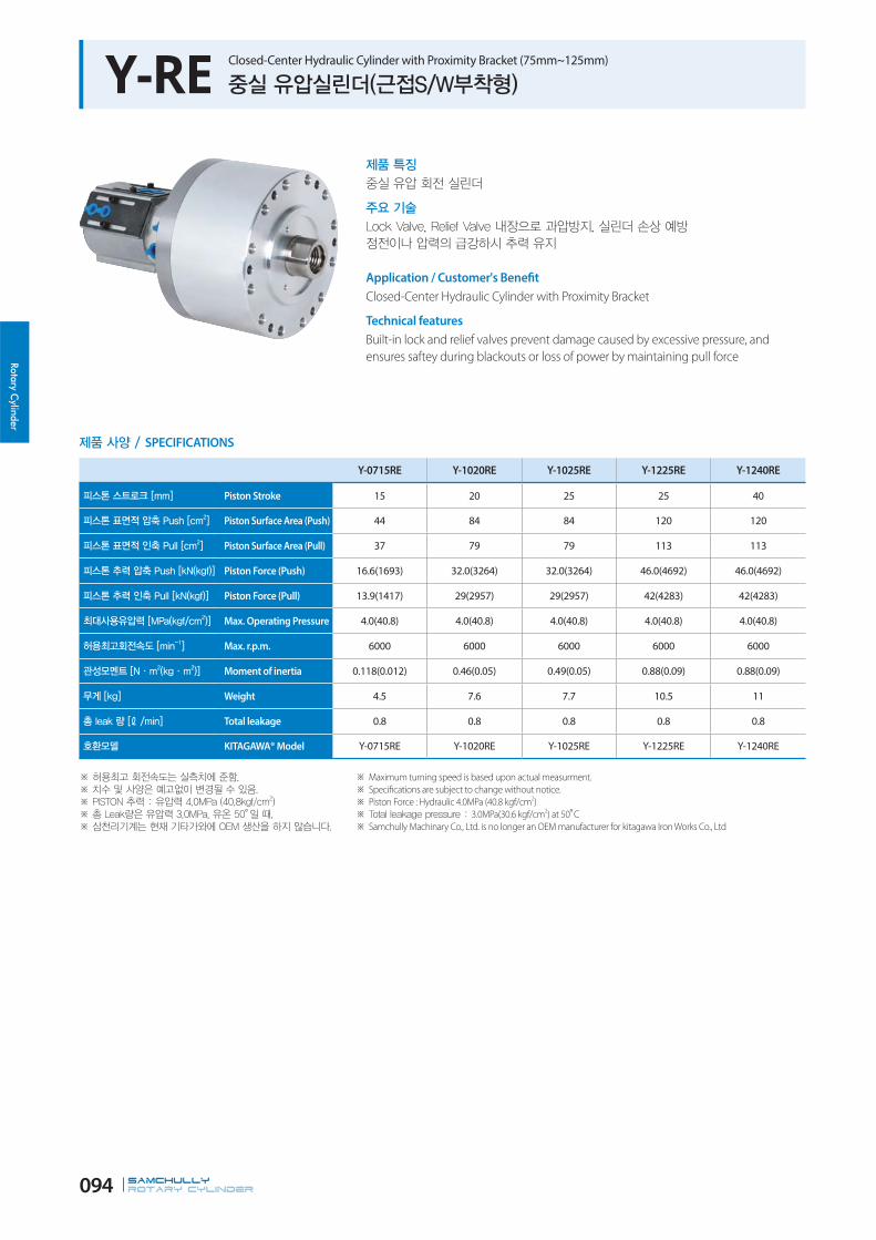
Rotary Cylinder
SAMCHULLYROTARY CYLINDER 094
Y-RE Closed-Center Hydraulic Cylinder with Proximity Bracket (75mm~125mm)
Application / Customer's Benefit
Closed-Center Hydraulic Cylinder with Proximity Bracket
Technical features
Built-in lock and relief valves prevent damage caused by excessive pressure, and
ensures saftey during blackouts or loss of power by maintaining pull force
SPECIFICATIONS
Y-0715RE Y-1020RE Y-1025RE Y-1225RE Y-1240RE
Piston Stroke 15 20 25 25 40
Piston Surface Area (Push) 44 84 84 120 120
Piston Surface Area (Pull) 37 79 79 113 113
Piston Force (Push) 16.6(1693) 32.0(3264) 32.0(3264) 46.0(4692) 46.0(4692)
Piston Force (Pull) 13.9(1417) 29(2957) 29(2957) 42(4283) 42(4283)
Max. Operating Pressure 4.0(40.8) 4.0(40.8) 4.0(40.8) 4.0(40.8) 4.0(40.8)
Max. r.p.m. 6000 6000 6000 6000 6000
Moment of inertia 0.118(0.012) 0.46(0.05) 0.49(0.05) 0.88(0.09) 0.88(0.09)
Weight 4.5 7.6 7.7 10.5 11
Total leakage 0.8 0.8 0.8 0.8 0.8
KITAGAWA® Model Y-0715RE Y-1020RE Y-1025RE Y-1225RE Y-1240RE
Maximum turning speed is based upon actual measurment.
Specifications are subject to change without notice.
Piston Force : Hydraulic 4.0MPa (40.8 kgf/cm2)
3.0MPa(30.6 kgf/cm2) at 50 C
Samchully Machinary Co., Ltd. is no longer an OEM manufacturer for kitagawa Iron Works Co., Ltd

Rota
ry C
ylin
der
SAMCHULLYROTARY CYLINDER 095
Y-0715RE Y-1020RE Y-1025RE Y-1225RE Y-1240RE
A 75 105 105 125 125
B 15 20 25 25 40
ΦC 104 135 135 160 160
ΦD 90 100 100 130 130
ΦE 65 80 80 110 110
ΦF 30 30 30 35 35
ΦG 21 21 21 25 25
H M20x2.5 M20x2.5 M20x2.5 M24x3.0 M24x3.0
J 32 35 35 44 44
K 227 252 257 260 306
L 161 163 163 163 194
M 66 89 94 97 112
N 127 152 157 160 175
P max. 46 45 45 51 65
P min. 31 25 20 26 25
Q 6-M6x20 6-M10x20 6-M10x20 6-M12x24 6-M12x24
R 133 158 163 166 181
S 23 23 23 23 -
T 41 41 41 41 -
DIMENSIONS

Rotary Cylinder
SAMCHULLYROTARY CYLINDER 096
Y-RE Closed-Center Hydraulic Cylinder with Proximity Bracket (150mm~250mm)
SPECIFICATIONS
Y-1530RE Y-1550RE Y-2035RE Y-2050RE Y-2560RE
Piston Stroke 30 50 35 50 60
Piston Surface Area (Push) 174 174 312 312 515
Piston Surface Area (Pull) 160 160 290 290 482
Piston Force (Push) 66.0(6732) 66.0(6732) 117.0(11934) 117.0(11934) 193(19541)
Piston Force (Pull) 60(6118) 60(6118) 108(11013) 108(11013) 180(18289)
Max. Operating Pressure 4.0(40.8) 4.0(40.8) 4.0(40.8) 4.0(40.8) 4.0(40.8)
Max. r.p.m. 5500 5500 5500 5500 2000
Moment of inertia 1.86(0.19) 1.96(0.20) 3.82(0.39) 4.12(0.42) 9.0(0.92)
Weight 14 14.8 22.5 23.5 85
Total leakage 0.8 0.8 0.8 0.8 0.8
KITAGAWA® Model Y-1530RE Y-1550RE Y-2035RE Y-2050RE -
Maximum turning speed is based upon actual measurment.
Specifications are subject to change without notice.
Piston Force : Hydraulic 4.0MPa (40.8 kgf/cm2)
3.0MPa(30.6 kgf/cm2) at 50 C
Samchully Machinary Co., Ltd. is no longer an OEM manufacturer for kitagawa Iron Works Co., Ltd
Application / Customer's Benefit
Closed-Center Hydraulic Cylinder with Proximity Bracket
Technical features
Built-in lock and relief valves prevent damage caused by excessive pressure, and
ensures saftey during blackouts or loss of power by maintaining pull force

Rota
ry C
ylin
der
SAMCHULLYROTARY CYLINDER 097
DIMENSIONS
Y-1530RE Y-1550RE Y-2035RE Y-2050RE Y-2560RE
A 150 150 200 200 250
B 30 50 35 50 60
ΦC 190 190 245 245 305
ΦD 130 130 145 145 220
ΦE 110 110 120 120 160
ΦF 45 45 55 55 65
ΦG 31 31 37 37 44
H M30x3.5 M30x3.5 M36x4.0 M36x4.0 M42x3.0
J 45 55 60 60 65
K 269 320 288 333 379
L 163 194 166 192 207
M 106 126 122 141 172
N 169 189 183 202 227
P max. 56 80 69 80 85
P min. 26 30 34 30 25
Q 6-M12x24 6-M12x24 12-M16x30 12-M16x30 12-M20x35
R 175 195 189 208 233
S 23 - 28 - -
T 41 - 46 - -

Rotary Cylinder
SAMCHULLYROTARY CYLINDER 098
DY Double-Piston Hydraulic Cylinder
Application / Customer's Benefit
Dual piston Suitable for 2+2 chucks
Technical features
Suitable with chucks having face drivers and ejectors
SPECIFICATIONS
Maximum turning speed is based upon actual measurment.
Specifications are subject to change without notice.
DY-12530 DY-16030
Piston A Piston B Piston A Piston B
Piston Stroke 30 30 80 30
Push [kN(kgf)] Piston Force (Push) 43(4492) 13(1382) 74(7526) 20(2112)
Pull [kN(kgf)] Piston Force (Pull) 36(3724) 12.5(1320) 68(6950) 18.5(1958)
Push [cm²] Piston Surface Area (Push) 117 36 196 55
Pull [cm²] Piston Surface Area (Pull) 97 33 181 51
[MPa(kgf/cm²)] Max. Operating Pressure 4.0(40) 4.0(40)
[min-¹] Max. r.p.m. 5000 3000
[kg] Weight 15 27
[kg·m²] Moment of inertia 0.09 0.40

Rota
ry C
ylin
der
SAMCHULLYROTARY CYLINDER 099
DY-12530 DY-16030
ΦA 165 205
ΦB(h6) 110 125
ΦC 142 180
ΦD 55 50
ΦE 25 25
F 6-M10 C'bore 6-M12 C'bore
G M16 x 2.0P M16 x 2.0P
H M45 x 1.5P M42 x 1.5P
J 164 220
K 305 411
L 374 503
S1 Max.60 / Min.30 Max.127 / Min.97
S2 Max.45 / Min.15 Max.97 / Min.17
DIMENSIONS
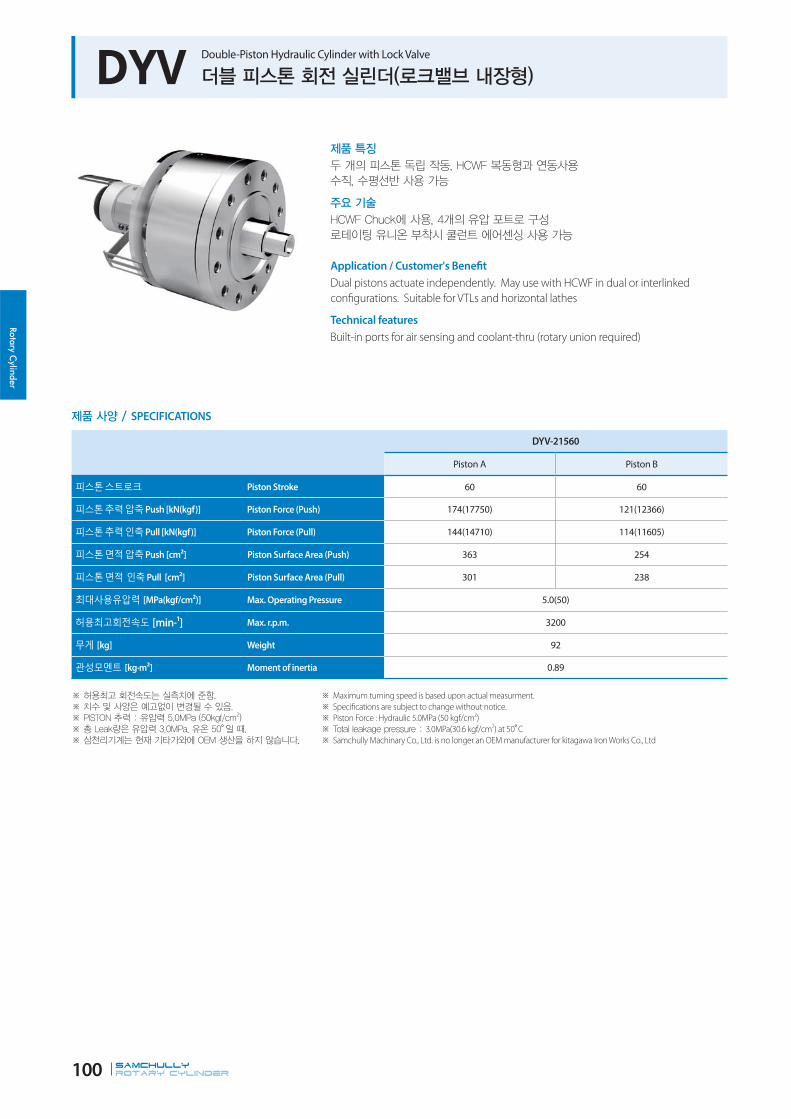
Rotary Cylinder
SAMCHULLYROTARY CYLINDER 100
DYV Double-Piston Hydraulic Cylinder with Lock Valve
Application / Customer's Benefit
Dual pistons actuate independently. May use with HCWF in dual or interlinked
configurations. Suitable for VTLs and horizontal lathes
Technical features
Built-in ports for air sensing and coolant-thru (rotary union required)
SPECIFICATIONS
DYV-21560
Piston A Piston B
Piston Stroke 60 60
Push [kN(kgf)] Piston Force (Push) 174(17750) 121(12366)
Pull [kN(kgf)] Piston Force (Pull) 144(14710) 114(11605)
Push [cm²] Piston Surface Area (Push) 363 254
Pull [cm²] Piston Surface Area (Pull) 301 238
[MPa(kgf/cm²)] Max. Operating Pressure 5.0(50)
[min-¹] Max. r.p.m. 3200
[kg] Weight 92
[kg·m²] Moment of inertia 0.89
Maximum turning speed is based upon actual measurment.
Specifications are subject to change without notice.
Piston Force : Hydraulic 5.0MPa (50 kgf/cm2)
3.0MPa(30.6 kgf/cm2) at 50 C
Samchully Machinary Co., Ltd. is no longer an OEM manufacturer for kitagawa Iron Works Co., Ltd
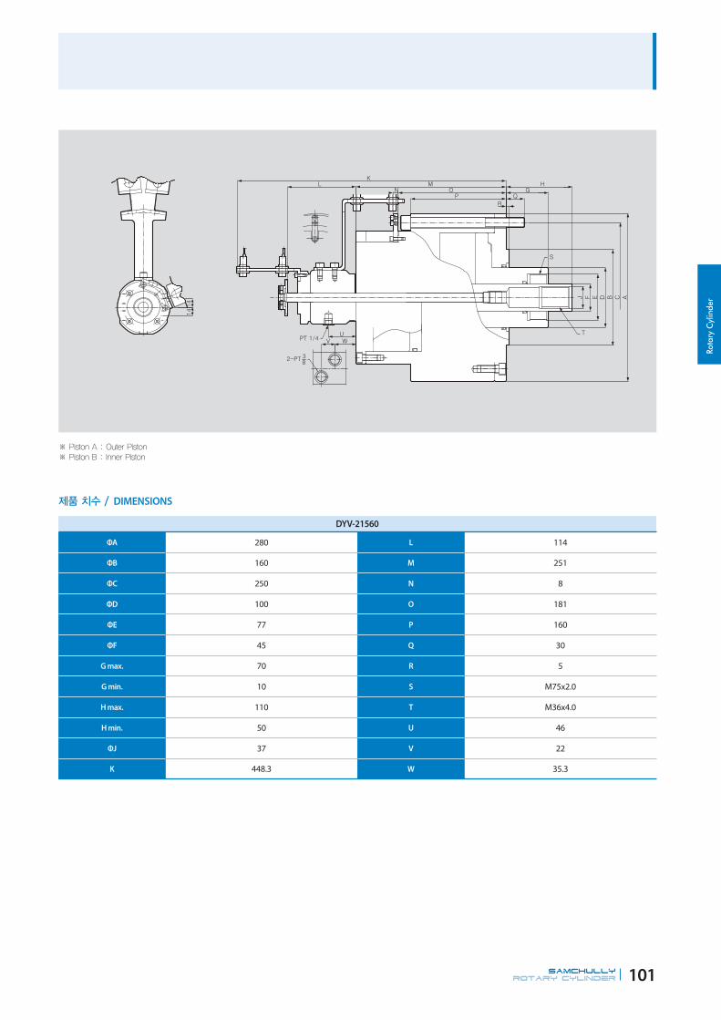
Rota
ry C
ylin
der
SAMCHULLYROTARY CYLINDER 101
DYV-21560
ΦA 280 L 114
ΦB 160 M 251
ΦC 250 N 8
ΦD 100 O 181
ΦE 77 P 160
ΦF 45 Q 30
G max. 70 R 5
G min. 10 S M75x2.0
H max. 110 T M36x4.0
H min. 50 U 46
ΦJ 37 V 22
K 448.3 W 35.3
DIMENSIONS

Rotary Cylinder
SAMCHULLYROTARY CYLINDER 102
AY-R Closed-Center Pneumatic Cylinder
Application / Customer's Benefit
Closed-Center Pneumatic Cylinder
Suitable for cutting thin material
SPECIFICATIONS
Maximum turning speed is based upon actual measurment.
Specifications are subject to change without notice.
AY-1005R AY-1315R AY-1720R AY-2225R AY-2730R
Piston Stroke 5 15 20 25 30
Piston Surface Area (Push) 78.5 131 225 378 570.4
Piston Surface Area (Pull) 73.6 128 220.1 371.1 560.8
Piston Force (Push) 5.4(552) 7.7(786) 13.23(1350) 22.2(2268) 33.5(3422)
Piston Force (Pull) 5.1(518) 7.5(770) 12.9(1320) 21.8(2226) 33.0(3364)
Max. Operating Pressure 8(0.82) 8(0.82) 8(0.82) 8(0.82) 8(0.82)
Max. r.p.m. 5000 5000 5000 4000 3000
Weight 4.1 5.2 8.3 13.3 18.7
Moment of inertia 0.686(0.07) 0.686(0.07) 1.078(0.11) 2.450(0.25) 7.350(0.75)

Rota
ry C
ylin
der
SAMCHULLYROTARY CYLINDER 103
49
20˚20˚
AY-1005R AY-1315R AY-1720R AY-2225R AY-2730R
A 100 130 170 220 270
B 5 15 20 25 30
ΦC 128 156 200 255 305
ΦD 90 90 100 130 130
ΦE(h7) 65 65 80 110 110
ΦF 20 20 25 30 35
G max. 30 35 65 71 76
G min. 25 20 45 46 46
H 5 5 5 5 5
J 53 63 82 93 103
K 70 70 70 70 74.5
L 123 133 152 163 177.5
M 79 89 108 119 133.5
N M5 M6 M7 M8 M9
Q M6x11 M6x11 M10x16 M12x20 M12x20
P M12x22 M12x22 M16x30 M20x35 M24x40
DIMENSIONS

SCROLL CHUCK
삼천리기계는 터닝센터 그리고 머시닝센터에서의 다양하고 광범위한
머신툴 토탈 솔루션을 제공하는 글로벌 기업입니다.
제조산업의 생산성 향상과 고정밀 가공을 위한 끊임없는 신제품 개발과 기술혁신이야 말로
삼천리기계가 지향하는 미래 가치입니다.
Samchully is the global machine tool's total company which has been supplied various
and wide range of solutions for turning and machining center.we are aiming for the
improvement of productivity and high precision machining to manufacturing industry
through awesome products and technology innovation.

SC
FSC
TC
FTC
ST
SF
SCS
SL
Standard Scroll Chuck(Hard Jaws)
Standard Front Mounting Scroll Chuck(Hard Jaws)
Standard Scroll Chuck(Soft & Hard Top Jaws)
Front Mounting Scroll Chuck(Soft & Hard Top Jaws)
2-Jaw Scroll Chuck(Soft Top Jaws)
4-Jaw Scroll Chuck(Hard Jaws)
6-Jaw Scroll Chuck(Hard Jaws)
Standard Slotter Chuck(Hard Jaws)
106P
108P
109P
110P
112P
113P
114P
115P
MU
IC
IC
Manual Chuck
Independent Chuck(Hard Jaws)
Independent Chuck(Hard Jaws)
116P
118P
120P
Mega Bore

Scroll Chuck
SAMCHULLYMANUAL CHUCK106
SC Standard Scroll Chuck (Hard Jaws)
Application / Customer's Benefit
Scroll chuck with hardened jaws
Technical features
Includes external and internal gripping jaws.
DIMENSIONS
SC-85(3") SC-110(4") SC-130(5") SC-165(6") SC-190(7")
ΦA 85 110 130 167 192
B 44.1 58 60 65 75
ΦC(H6) 60 80 100 130 155
ΦD 73 95 115 147 172
ΦE 16 24 34 47 57
F 3.5 4.5 4.5 5 5
G 3-M6 3-M8 3-M8 3-M10 3-M10
H 35 44 50 65 75
J 11 14 16 19 22
K 14.6 20.0 20.1 25.07 30.06
L 7 8 8 10 11
M 17 24.5 22.5 24 27.5
N 27.1 32.35 37 41 47.5
P 13 16 16 20 20
SPECIFICATIONS
SC-85 (3") SC-110 (4") SC-130 (5") SC-165 (6") SC-190 (7")
Max. Static Gripping Force 9(918) 12(1224) 15(1530) 31(3161) 31(3161)
Clamping Range 2~70 3~94 3~110 3~160 4~180
24~64 29~84 33~100 48~150 56~170
Handle Torque 29.4(3.0) 44.1(4.1) 63.7(6.5) 88.3(9.0) 107.9(11.0)
Max. r.p.m. 2500 2500 2500 4000 3500
Weight 1.5 3.1 4.4 11.4 12.2
Moment of inertia 0.05(0.005) 0.17(0.017) 0.35(0.036) 1.18(0.12) 2.35(0.24)
Maximum turning speed is based upon actual measurment.
176p 175p
Adaptor H/S Jaw

Scro
ll C
huck
SAMCHULLYMANUAL CHUCK 107
SC Standard Scroll Chuck (Hard Jaws)
Application / Customer's Benefit
Scroll chuck with hardened jaws
Technical features
Includes external and internal gripping jaws.
DIMENSIONS
SC-230(9") SC-273(10") SC-310(12") SC-355(14") SC-405(16")
ΦA 232 273 310 355 405
B 84 86 96 110 114.5
ΦC(H6) 190 230 260 300 345
ΦD 210 250 285 328 375
ΦE 75 89 100 105 130
F 6 6 7 8 8
G 3-M12 3-M12 3-M12 6-M12 6-M12
H 85 98 110 133 133
J 24 28 30 35 35
K 35.04 40.02 45.08 62.98 63
L 12 12 14 14 15
M 29.5 31.5 31.5 42.4 43
N 54.5 54.5 64.5 67.6 71.5
P 25 25 25 36 36
SPECIFICATIONS
SC-230 (9") SC-273 (10") SC-310 (12") SC-355 (14") SC-405 (16")
Max. Static Gripping Force 37(3773) 46(4691) 55(5608) 40.5(4130) 45(4589)
Clamping Range 5~200 5~260 10~300 25~315 25~346
62~210 70~250 86~290 107~290 113~324
Handle Torque 147(15.0) 176.5(18.0) 206(21.0) 225.6(23.0) 245(25.0)
Max. r.p.m. 2900 2500 2200 1500 1500
Weight 21.2 28 41 54 74
Moment of inertia 6.27(0.64) 9.90(1.01) 23.0(2.35) 37.2(3.8) 67.6(6.9)
Maximum turning speed is based upon actual measurment.
176p 175p
Adaptor H/S Jaw

Scroll Chuck
SAMCHULLYMANUAL CHUCK108
FSC Standard Front-Mounting Scroll Chuck (Hard Jaws)
SPECIFICATIONS
FSC-165(6") FSC-190(7") FSC-230(9") FSC-273(10") FSC-310(12")
Max. Static Gripping Force 31(3161) 31(3161) 37(3773) 46(4691) 55(5608)
Clamping Range 3~160 4~180 5~220 5~260 10~300
48~150 56~170 62~210 70~250 86~290
Handle Torque 88.3(9.0) 107.9(11.0) 147(15.0) 176.5(18.0) 206(21.0)
Max. r.p.m. 4000 3500 2900 2500 2200
Weight 11.4 12 21.2 28 41
Moment of inertia 1.18(0.12) 2.35(0.24) 6.27(0.64) 9.90(1.01) 23.0(2.35)
Maximum turning speed is based upon actual measurment.
Specifications are subject to change without notice.
DIMENSIONS
FSC-165(6") FSC-190(7") FSC-230(9") FSC-273(10") FSC-310(12")
ΦA 167 192 232 273 310
B 65 75 84 86 96
ΦC(H6) 130 155 190 230 260
ΦD 147 172 210 250 285
ΦE 45 57 75 89 100
F 5 5 6 6 7
G 3-M10 3-M10 3-M12 3-M12 3-M12
H 65 75 87 98 110
J 19 22 24 28 30
K 25.07 30.06 35.04 40.02 45.08
L 10 11 12 12 14
M 24 27.5 29.5 31.5 31.5
N 41 47.5 54.5 54.5 64.5
P 20 20 25 25 25
Q 3-M10x70 3-M10x85 3-M12x95 3-M12x95 3-M12x110
R 16 17 24 20 27
Application / Customer's Benefit
Scroll chuck with hardened jaws (Front mounting).
Technical features
Includes external and internal gripping jaws.

Scro
ll C
huck
SAMCHULLYMANUAL CHUCK 109
TC Standard Scroll Chuck (Soft and Hard top Jaws)
DIMENSIONS
Maximum turning speed is based upon actual measurment.
SPECIFICATIONS
TC-190(7") TC-230(9") TC-273(10") TC-310(12")
Max. Static Gripping Force 31(3161) 37(3773) 46(4691) 55(5608)
Clamping Range 4~180 5~220 5~260 10~300
56~170 62~210 70~250 86~290
Handle Torque 107.9(11.0) 147(15.0) 173.5(18.0) 206(21.0)
Max. r.p.m. 3500 2900 2500 2200
Weight 12.2 21.2 28 41
Moment of inertia 2.35(0.24) 6.24(0.64) 9.90(1.01) 23.0(2.35)
TC-190(7") TC-230(9") TC-273(10") TC-310(12")
ΦA 192 232 273 310
B 78.7 83.7 88 96
ΦC 155 190 230 260
ΦD 172 210 250 285
ΦE 57 75 89 100
F 5 6 6 7
G 3-M10 3-M12 3-M12 3-M12
H 80.5 90.5 103.5 115.5
J 28 32 35 40
K 42.8 53.8 57.82 56.08
L 11 12 12 14
M 27.5 29.5 31.5 31.5
N 51.2 54.2 56.5 64.5
P 20 25 25 25
Mounting bolt 3-M10 3-M12 3-M12 3-M12
Application / Customer's Benefit
Two-piece, base jaw and to jaw configuration(Includes hard and soft jaws).
Technical features
Reversible hard jaws.
178p
H/S Jaw

Scroll Chuck
SAMCHULLYMANUAL CHUCK110
SPECIFICATIONS
FTC-165 FTC-190(7") FTC-230(9") FTC-273(10") FTC-310(12")
Max. Static Gripping Force 31(3161) 31(3161) 37(3773) 46(4691) 55(5608)
Clamping Range 3~160 4~180 5~220 5~260 10~300
55~150 56~170 62~210 70~250 86~290
Handle Torque 88(9.0) 107.9(11.0) 147(15.0) 176.5(18.0) 206(21.0)
Max. r.p.m. 4000 3500 2900 2500 2200
Weight 9 12.2 21.2 28 41
Moment of inertia 0.033 0.62(0.063) 1.61(0.163) 2.63(0.265) 5.85(0.588)
FTC-460(18") FTC-535(21") FTC-610(24") FTC-810(32") FTC-1000(40")
Max. Static Gripping Force 65(6650) 73(7400) 80(8200) 110(11216) 110(11216)
Clamping Range 40~410 45~481 130~576 270~810 340~990
152~436 155~499 235~592 390~800 450~940
Handle Torque 255.0(26) 313.9(32) 372.7(38) 588(60) 588(60)
Max. r.p.m. 1200 950 850 650 470
Weight 106 182 238 480 780
Moment of inertia 124(12.6) 287(29.3) 488(49.8) 598(61) 598(61)
Maximum turning speed is based upon actual measurment.
FTC Front-Mounting Scroll Chuck (Soft and Hard top Jaws)
Application / Customer's Benefit
Front mounting scroll chuck with two-piece jaws.
Technical features
Reversible hard jaws.
177p 178p
Handle H/S Jaw

Scro
ll C
huck
SAMCHULLYMANUAL CHUCK 111
DIMENSIONS
FTC-165 FTC-190(7") FTC-230(9") FTC-273(10") FTC-310(12") FTC-460(18") FTC-535(21") FTC-610B(24") FTC-810(32") FTC-1000(40")
ΦA 167 192 232 273 310 460 535 610 810 1000
B 69 78.7 83.7 88 96 114 143 143 180 196
ΦC(H6) 130 155 190 230 260 400 270 380 520 910
ΦD 147 172 210 250 285 425 235 315 425 510
ΦE 47 57 75 89 100 190 195 275 375 580
F 5 5 6 6 7 8 12 14 16 16
G 3-M10 3-M10 3-M12 3-M12 3-M12 - - - - -
H 67 80.5 90.5 103.5 115.5 140(130) 150(130) 130 248 286
J 26 28 32 35 40 50 50 50 70 70
K 38.5 42.8 53.8 57.82 56.08 80 82 82 95 95
L 10 11 12 12 14 17 22 22 22 22
M 24 27.5 29.5 31.5 31.5 38.2 57.5 57.5 64 69.5
N 45 51.2 54.2 56.5 64.5 76 85.5 85.5 116 126.5
P 20 20 25 25 25 - - - - -
Q 3-M10x75 3-M10x90 3-M12x95 3-M12x95 3-M12x110 3-M16x125 3-M20x140 3-M20x140 3-M24x140 3-M24x190
R 17 22 24 20 27 29 32 33 32 35

Scroll Chuck
SAMCHULLYMANUAL CHUCK112
ST 2Jaw Scroll Chuck (Soft top Jaws)
Maximum turning speed is based upon actual measurment.
SPECIFICATIONS
ST-190(7") ST-230(9") ST-273(10") ST-310(12")
Max. Static Gripping Force 20.7(2110) 24.7(2518) 46(4691) 55(5608)
Clamping Range 4~180 5~220 5~260 10~300
62~170 70~210 70~250 86~290
Handle Torque 73.5(7.5) 98(10.0) 176.5(18.0) 206(21.0)
Max. r.p.m. 3500 2900 2500 2200
Weight 12.6 21.4 28 41
Moment of inertia 2.55(0.26) 6.27(0.64) 9.90(1.01) 23.0(2.35)
DIMENSIONS
ST-190(7") ST-230(9") ST-273(10") ST-310(12")
ΦA 192 232 273 310
B 78.7 83.7 88 96
ΦC(H6) 155 190 230 260
ΦD 172 210 250 285
ΦE 57 75 89 100
F 5 6 6 7
G 3-M10 3-M12 3-M12 3-M12
H 88 100 110 125
J 32 32 35 40
K 44.8 49.8 54.32 50.58
L 11 12 12 14
M 27.5 29.5 31.5 31.5
N 51.2 54.2 56.5 64.5
P 20 25 25 25
Application / Customer's Benefit
Front mounting scroll chuck with two-piece jaws.
Technical features
Suitable for clamping valves, pipe fittings and irregular parts.
176p 175p
Adaptor H/S Jaw

Scro
ll C
huck
SAMCHULLYMANUAL CHUCK 113
SF 4-Jaw Scroll Chuck (Hard Jaws)
DIMENSIONS
SPECIFICATIONS
SF-190(7") SF-230(9") SF-273(10") SF-310(12")
Max. Static Gripping Force 31(3161) 37(3773) 46(4691) 55(5608)
Clamping Range 4~180 5~220 5~260 10~300
56~170 62~210 70~250 86~290
Handle Torque 107.9(11.0) 147(15.0) 176.5(18.0) 206(21.0)
Max. r.p.m. 3500 2900 2500 2200
Weight 12.5 21.5 28 41
Moment of inertia 2.45(0.25) 6.37(0.65) 9.90(1.01) 23.0(2.35)
Maximum turning speed is based upon actual measurment.
SF-190(7") SF-230(9") SF-273(10") SF-310(12")
ΦA 192 232 273 310
B 75 84 86 96
ΦC(H6) 155 190 230 260
ΦD 172 210 250 285
ΦE 57 75 89 100
F 5 6 6 7
G 3-M10 3-M12 3-M12 3-M12
H 75 85 98 110
J 22 24 28 30
K 30.06 35.04 40.02 45.08
L 11 12 12 14
M 27.5 29.5 31.5 31.5
N 47.5 54.5 54.5 64.5
P 20 25 25 25
Application / Customer's Benefit
4-Jaw Scroll chuck.
Technical features
Suitable for clamping square parts.
176p 175p
Adaptor H/S Jaw
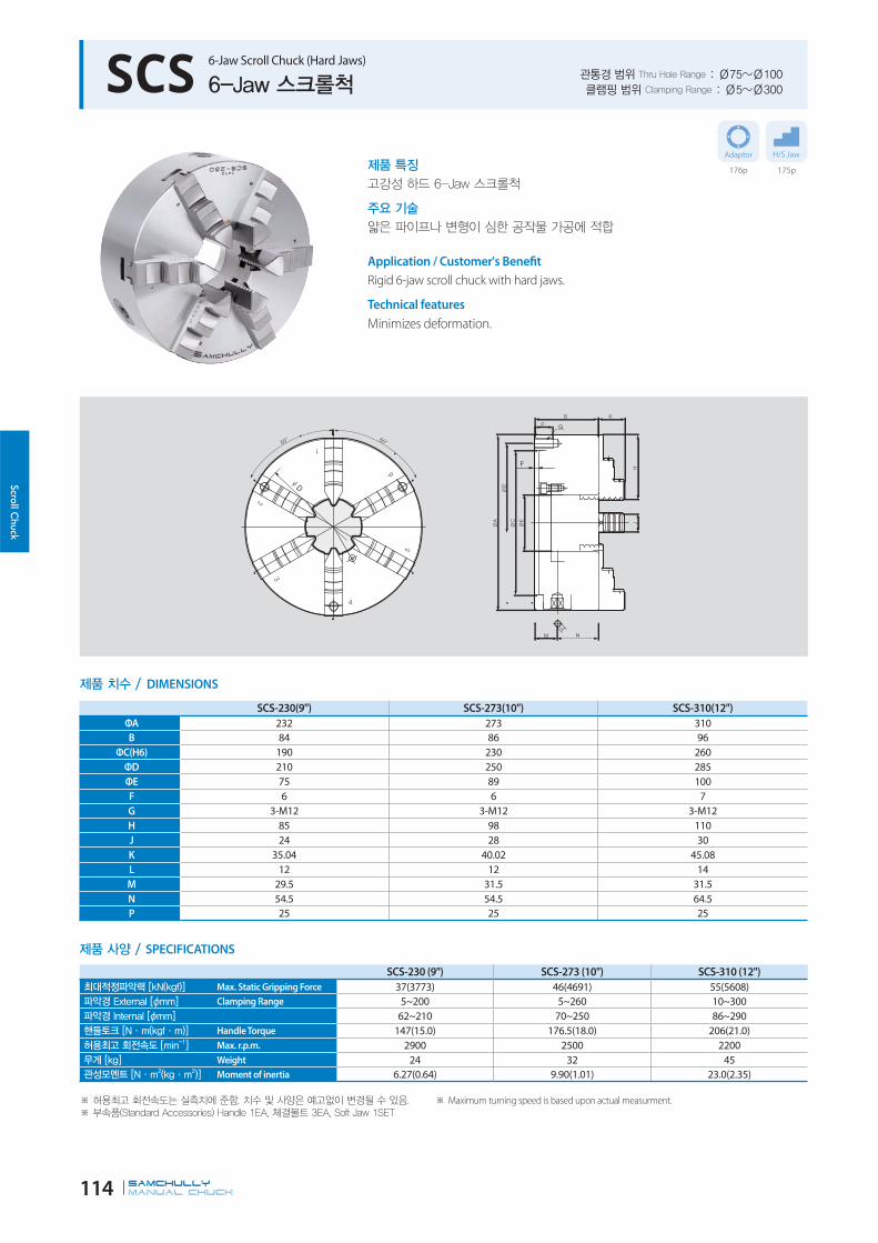
Scroll Chuck
SAMCHULLYMANUAL CHUCK114
SCS 6-Jaw Scroll Chuck (Hard Jaws)
Application / Customer's Benefit
Rigid 6-jaw scroll chuck with hard jaws.
Technical features
Minimizes deformation.
DIMENSIONS
SPECIFICATIONS
SCS-230 (9") SCS-273 (10") SCS-310 (12")
Max. Static Gripping Force 37(3773) 46(4691) 55(5608)
Clamping Range 5~200 5~260 10~300
62~210 70~250 86~290
Handle Torque 147(15.0) 176.5(18.0) 206(21.0)
Max. r.p.m. 2900 2500 2200
Weight 24 32 45
Moment of inertia 6.27(0.64) 9.90(1.01) 23.0(2.35)
Maximum turning speed is based upon actual measurment.
SCS-230(9") SCS-273(10") SCS-310(12")
ΦA 232 273 310
B 84 86 96
ΦC(H6) 190 230 260
ΦD 210 250 285
ΦE 75 89 100
F 6 6 7
G 3-M12 3-M12 3-M12
H 85 98 110
J 24 28 30
K 35.04 40.02 45.08
L 12 12 14
M 29.5 31.5 31.5
N 54.5 54.5 64.5
P 25 25 25
176p 175p
Adaptor H/S Jaw

Scro
ll C
huck
SAMCHULLYMANUAL CHUCK 115
SL Standard Slotter Chuck (Hard Jaws)
Application / Customer's Benefit
Easy installation and operation
Technical features
Mounted adaptor plate
DIMENSIONS
SPECIFICATIONS
SL-08 SL-10 SL-12
Max. Static Gripping Force 37(3,800) 46(4,700) 55(5,620)
Clamping Range 4~182 4~220 5~266
58~174 68~212 80~263
Handle Torque 117.7(13) 176.5(18) 196.2(20)
Compatibility Jaw SC-230 SC-273 SC-310
Weight 17.6 27.7 40
Maximum turning speed is based upon actual measurment.
SL-08 SL-10 SL-12ΦA 215 255 305
ΦB(HC6) 110 125 160
ΦC 60 76 100
ΦD 190.5 230 280
ΦE 240 286 340
F 35.04 40.02 45.05
G 64 72 76
H 85 98 110
I 25 28 30
J 4 4.5 5
K 11 12 14
L M10 M12 M12
M 266 315 370
N 17 20 22
O 13 15 17
177p 175p
Handle H/S Jaw

Scroll Chuck
SAMCHULLYMANUAL CHUCK116
MU Manual Chuck
Application / Customer's Benefit
Easy to operate scroll chuck with stepped jaws.
Maximum turning speed is based upon actual measurment.
T-Slot can be changeed at the request.
SPECIFICATIONS
MU-32 MU-40 MU-50 MU-63
Box Jaw Stroke 60 60 50 50
Max. Static Gripping Force. - - - -
Clamping Range 681 885 1050 1450
112 316 281 321
Max. r.p.m. 650 500 360 400
Weight 350 800 1250 1600
Moment of inertia - - - -

Scro
ll C
huck
SAMCHULLYMANUAL CHUCK 117
*2Step-Manual JawMJ60-125
*2Step-Manual JawMJ80-180
MU-32, 40 MU-50, 63
DIMENSIONS
MU-32 MU-40 MU-50 MU-63
ΦA 800 1000 1250 1600
ΦB(76) 150 150 180 240
ΦC 380 520 520 1020
ΦD 330.2 463.6 463.6 956
ΦE 85 178 220 320
F 99.5 99.5 124.5 124.5
G max 340.5 442.5 525 725
J 312.5 312.5 367.5 427.5
K 6-M24x80L 6-M24x90L 6-M24x100L 12-M24x140L
M 210.5 210.5 205 205
N 80.5 80.5 80.5 80.5
P 166 268 345 365
Q 86 188 170.5 190.5
R min 56 158 140.5 160.5
S 6 8 8 8
T 34 41 54 38

Scroll Chuck Sc
roll
Chu
ck
SAMCHULLYMANUAL CHUCK118
IC Independent Chuck (Hard Jaws) (200mm - 400mm)
단동척
제품 특징각각의 죠가 개별 작동하는 표준 단동척
주요 기술단동척(10" 이상 척에는 T-Slot 홈 가공 채택)
Application / Customer's BenefitIndependent chuck with independently moving jaws.
Technical featuresChucks 10 inches and larger add versatility with t-slots .
D
제품 치수 / DIMENSIONS
제품 사양 / SPECIFICATIONS
IC-08 IC-10 IC-12 IC-14 IC-16최대적정파악력 [kN(kgf)] Max. Static Gripping Force 1000 1400 1600 1700 2000파악경 External [ɸmm] Clamping Range 75 95 125 155 190파악경 Internal [ɸmm] 185 220 265 310 360허용최고 회전속도 [min-1] Max. r.p.m. 1600 1600 1400 1400 1200무게 [kg] Weight 14.8 21 29.5 40 56.5관성모멘트 [N·m2(kg·m2)] Moment of inertia 0.3 0.6 1.4 2.9 4.5
※ 허용최고 회전속도는 실측치에 준함. 치수 및 사양은 예고없이 변경될 수 있음.※ 부속품(Standard Accessories) Handle 1EA, 체결볼트 4EA※ IC-32 이상 주문 생산
※ Maximum turning speed is based upon actual measurment.※ Specifications are subject to change without notice.
IC-08 IC-10 IC-12 IC-14 IC-16A 200 250 300 350 400B 75 80 88 90 100
C1 200 165 186 210 230
C2 175 150 170 190 210
D 155 125 140 160 180
E 50 55 65 75 90
F 6 6 6 8 8
G M12 M12 M12 M12 M16
H 75 90 100 110 120
J 30 30 35 35 40
K 30 35 40 45 50L 10 10 12 12 14
관통경 범위 Thru Hole Range : Ø50~Ø90클램핑 범위 Clamping Range : Ø75~Ø360
176p 175p
Adaptor H/S Jaw

Scroll Chuck Sc
roll
Chu
ck
SAMCHULLYMANUAL CHUCK 119
제품 특징각각의 죠가 개별 작동하는 표준 단동척
주요 기술단동척(10" 이상 척에는 T-Slot 홈 가공 채택)
Application / Customer's BenefitIndependent chuck with independently moving jaws.
Technical featuresChucks 10 inches and larger add versatility with t-slots .
※ 허용최고 회전속도는 실측치에 준함. 치수 및 사양은 예고없이 변경될 수 있음.※ 부속품(Standard Accessories) Handle 1EA, 체결볼트 4EA※ IC-32 이상 주문 생산
※ Maximum turning speed is based upon actual measurment.※ Specifications are subject to change without notice.
IC Independent Chuck (Hard Jaws) (450mm - 813mm)
단동척
D
제품 치수 / DIMENSIONS
제품 사양 / SPECIFICATIONS
IC-18 IC-20 IC-24 IC-28 IC-32최대적정파악력 [kN(kgf)] Max. Static Gripping Force 2000 2200 2300 2396 2447파악경 External [ɸmm] Clamping Range 220 250 320 385 485파악경 Internal [ɸmm] 405 450 550 650 750허용최고 회전속도 [min-1] Max. r.p.m. 1200 900 900 900 600무게 [kg] Weight 70 90 150 247 357관성모멘트 [N·m2(kg·m2)] Moment of inertia 7 11.8 25.3 58 103
IC-18 IC-20 IC-24 IC-28 IC-32A 450 500 600 710 800B 105 110 120 120 120
C1 230 272 330 382 440
C2 250 250 300 350 400
D 200 220 260 300 350
E 100 110 120 140 140
F 8 8 10 12 12
G M16 M16 M20 M20 M20
H 130 140 160 180 200
J 40 45 50 50 60
K 55 60 70 70 89L 14 14 14 14 24
관통경 범위 Thru Hole Range : Ø100~Ø140클램핑 범위 Clamping Range : Ø220~Ø750
176p 175p
Adaptor H/S Jaw

Scroll Chuck
SAMCHULLYMANUAL CHUCK120
IC Independent Chuck (Hard Jaws) (500mm - 600mm)
DIMENSIONS
SPECIFICATIONS
IC-2018 IC-2023 IC-2423 IC-2427
Max. Static Gripping Force 27.4(2800) 27.4(2800) 28.5(2904) 30(3056)
Clamping Range 460 460 550 550
450 450 530 550
Max. r.p.m. 800 800 800 800
Weight 180 170 350 340
Moment of inertia 54.9(5.6) 51.41(5.3) 61.74(6.3) 61.74(6.3)
Soft & Hard jaws are basic components.
Maximum turning speed is based upon actual measurment.
Specifications are subject to change without notice.
IC-2018 IC-2023 IC-2423 IC-2427
ΦA 500 500 600 600
B 110 110 140 140
ΦC2 260 300 420 420
ΦD 230 270 463.6 463.6
ΦE 180 230 230 275
F - 8 10 10
G M16 M16 M24 M24
H 135 140 200 200
J 45 45 60 60
K 83.45 83.45 104.15 104.15
L 14 14 24 24
Application / Customer's Benefit
High durability by applying advanced cast irons.
Suitable for machining materials such as oil pipe lines and industrial pipes.
Indepent clamps of each four jaws.
Technical features
Best for comatibility as detailed size management and high-quality
Ideal for using general lathe(KS, JIS standard).

Scro
ll C
huck
SAMCHULLYMANUAL CHUCK 121
IC Independent Chuck (Hard Jaws) (600mm - 1000mm)
DIMENSIONS
SPECIFICATIONS
IC-2432 IC-3232 IC-3237 IC-4056
Max. Static Gripping Force 30(3056) 32.4(3300) 32.4(3300) 36(3700)
Clamping Range 550 750 750 920
550 730 730 840
Max. r.p.m. 800 600 600 480
Weight 340 463 490 660
Moment of inertia 61.74(6.3) 382(39) 382(39) -
Soft & Hard jaws are basic components.
Maximum turning speed is based upon actual measurment.
Specifications are subject to change without notice.
IC-2432 IC-3232 IC-3237 IC-4056
ΦA 600 800 800 1000
B 140 140 140 160
ΦC2 420 420 420 650
ΦD 463.6 463.6 463.6 700
ΦE 320 325 375 560
F 10 12 12 10
G M24 M24 M24 M22
H 200 200 200 200
J 60 60 60 60
K 104.15 104.15 104.15 104.15
L 24 24 24 -
Application / Customer's Benefit
High durability by applying advanced cast irons.
Suitable for machining materials such as oil pipe lines and industrial pipes.
Indepent clamps of each four jaws.
Technical features
Best for comatibility as detailed size management and high-quality
Ideal for using general lathe(KS, JIS standard).

VISE
삼천리기계는 터닝센터 그리고 머시닝센터에서의 다양하고 광범위한
머신툴 토탈 솔루션을 제공하는 글로벌 기업입니다.
제조산업의 생산성 향상과 고정밀 가공을 위한 끊임없는 신제품 개발과 기술혁신이야 말로
삼천리기계가 지향하는 미래 가치입니다.
Samchully is the global machine tool's total company which has been supplied various
and wide range of solutions for turning and machining center.we are aiming for the
improvement of productivity and high precision machining to manufacturing industry
through awesome products and technology innovation.
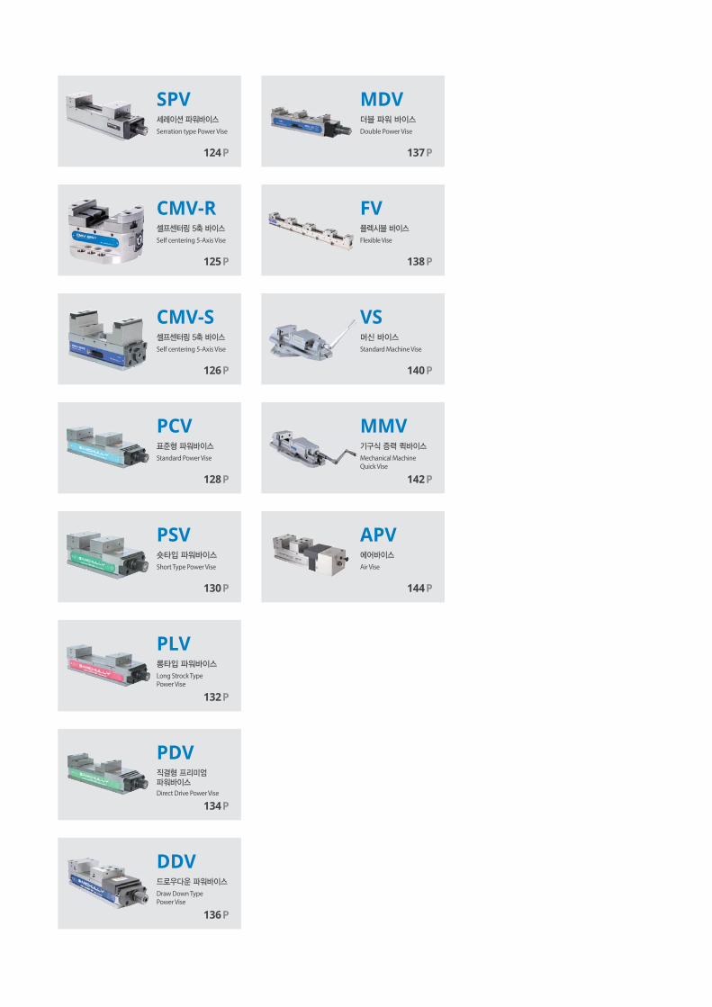
PCV
PSV
PLV
PDV
Standard Power Vise
Short Type Power Vise
Long Strock TypePower Vise
Direct Drive Power Vise
128P
130P
132P
134P
DDVDraw Down TypePower Vise
136P
MDVDouble Power Vise
137P
CMV-SSelf centering 5-Axis Vise
126P
SPVSerration type Power Vise
124P
CMV-RSelf centering 5-Axis Vise
125P
FV
VS
MMV
APV
Flexible Vise
Standard Machine Vise
Air Vise
Mechanical Machine Quick Vise
138P
140P
142P
144P

Vise
SAMCHULLYvise124
SPV Serration type Power Vise
Application / Customer's Benefit
Serration type for easy Jaw setting(Pitch=3.0mm)
Technical features
Minimal jaw set-up times
Sealed aginst chips by Operating unit structure
SPECIFICATIONS
Specifications are subject to change without notice.
SPV-156
Jaw Width 160
Jaw Height 115
Max. Opening 300
Total Height 175
Slider Height 115
Total Width 161
Total Length 595.5
Max.Gripping Force 60(6100)
Weight 73

Vise
SAMCHULLYvise 125
CMV-R 5-Axis Centering Vise
Application / Customer's Benefit
Self centering 5-Axis vise
Technical features
Repeats within 0.02mm or lower. Uses 1.5 pitch serration jaws
Able to use a variety of jaws for various work-piece
SPECIFICATIONS
Specifications are subject to change without notice.
CMV-125R
Jaw Width 125
Jaw Height 20
Max. Opening 125
Total Height 125
Slider Height 80
Total Width 125
Total Length Ø 200
Max.Gripping Force 20(2000)
Weight 17

Vise
SAMCHULLYvise126
CMV-S
SPECIFICATIONS
JAW ACCESSORIES
Specifications are subject to change without notice.
CMV-100S CMV-125S
Jaw Width 100 125
Jaw Height 10 10
Max. Opening 195 210
Total Height 160 185
Slider Height 150 175
Total Width 101 126
Total Length 285 332
Max.Gripping Force 20(2000) 20(2000)
Weight 18 24
5-Axis Centering Vise
Application / Customer's Benefit
Self centering 5-Axis vise
Technical features
Repeats within 0.02mm or lower
Able to use a variety of jaws for various work-piece

Vise
SAMCHULLYvise 127
DIMENSIONS
CMV-100S CMV-125S
A 262 301
B 160 185
C 100 125
D 285 332
E 12 19
F 160 160
G 85 100
H 150 175
I MAX. 195 MAX. 210
J Φ310 Φ364
K 15 15
L 37 37
M 180 180

Vise
SAMCHULLYvise128
PCV Standard Power Vise
Application / Customer's Benefit
High precision vise with torque presetter
Technical features
Mechanically boosted torque presetter helps prevent part deformation
SPECIFICATIONS
See the product dimension Table on the right.
PCV-100 (4") PCV-125 (5") PCV-160 (6") PCV-200 (8") PCV-250 (10")
Jaw Width 100 125 160 200 250
Jaw Height 40 50 60 70 80
Max. Opening 150 230 300 320 450
Total Height 115 135 160 180 195
Slider Height 75 85 100 110 115
Total Width 107 135 170 214 264
Total Length 400 505 595 638 810
Max.Gripping Force 25(2551) 35(3571) 60(6122) 60(6122) 80(8163)
Weight 25 43 65 100 200
Specifications are subject to change without notice.

Vise
SAMCHULLYvise 129
DIMENSIONS
PCV-100(4") PCV-125(5") PCV-160(6") PCV-200(8") PCV-250(10")
A 295 400 490 533 705
B 115 135 160 180 195
C 101 126 161 202 252
D 100 125 160 200 250
E 73 84 94 102 120
F 64 76 86 98 120
G 38.5 60 50 74 100
H 75 85 100 110 115
J 40 50 60 70 80
K 105.5 105.5 105.5 105.5 105.5
L 400.5 505.5 595.5 638.5 810.5
M 43 50 65 75 75
N 15 21 21 21 21
P 37 37 37 37 37
Q 95 95 95 95 95
R 180 180 180 180 180
S 150 230 300 320 450
T 60 72 72 72 72
U 14~26 15~31 15~31 15~31 15~31
V 22.5 30 30 30 30
W 107 135 170 214 267
X 14 18 18 18 22
Y 6 6 7 7 7
a M10 M10 M10 M10 M10
b M12x45 M16x65 M16x65 M16x65 M20x65
e 35 45 45 45 45
f 36.5 42 47 51 60
g 12 12 12 12 12
h 95 95 105 126 140
j 105 105 140 141 140
j1 - 105 140 141 140
j2 - - - - 140
n 112.5 145 145 177 221
r 288.0 360.5 450 461.5 584.5

Vise
SAMCHULLYvise130
PSV Short-Type Power Vise
Application / Customer's Benefit
High precision vise with torque presetter
Suitable for a wide range of workpiece sizes
Technical features
Mechanically boosted torque presetter helps prevent part deformation
SPECIFICATIONS
Specifications are subject to change without notice.
See the product dimension Table on the right.
PSV-125(5") PSV-160(6")
Jaw Width 125 160
Jaw Height 50 60
Max. Opening 125 160
Total Height 135 160
Slider Height 85 100
Total Width 135 170
Total Length 400.5 455.5
Max.Gripping Force 35(3571) 60(6122)
Weight 41 62

Vise
SAMCHULLYvise 131
DIMENSIONS
PSV-125(5") PSV-160(6")
A 295 350
B 135 160
C 126 161
D 125 160
E 84 94
F 76 86
G 60 50
H 85 100
J 50 60
K 105.5 105.5
L 400.5 455.5
M 50 65
N 21 21
P 37 37
Q 95 95
R 180 180
S 125 160
T 72 72
U 15~31 15~31
V 30 30
W 135 170
X 18 18
Y 6 7
a M10 M10
b M16x65 M16x65
e 45 45
f 42 47
g 12 12
h 95 105
j 105 140
j1 105 140
n 145 145
r 255.5 310

Vise
SAMCHULLYvise132
PLV Long Stroke Power Vise
Application / Customer's Benefit
High precision vise with torque presetter
Suitable for a wide range of workpiece sizes
Technical features
Mechanically boosted torque presetter helps prevent part deformation
SPECIFICATIONS
See the product dimension Table on the right.
PLV-125(5”) PLV-160(6”) PLV-200(8”)
Jaw Width 125 160 200
Jaw Height 50 60 70
Max. Opening 420 354 405
Total Height 135 160 180
Slider Height 85 100 110
Total Width 135 170 214
Total Length 700.5 647.5 723.5
Max.Gripping Force 35(3571) 60(6122) 60(6122)
Weight 47 70 110
Specifications are subject to change without notice.

Vise
SAMCHULLYvise 133
DIMENSIONS
PLV-125(5") PLV-160(6") PLV-200(8")
A 595 542 618
B 135 160 180
C 126 161 202
D 125 160 200
E 84 94 102
F 76 86 98
G 60 82 74
H 85 100 110
J 50 60 70
K 105.5 105.5 105.5
L 700.5 647.5 723.5
M 50 65 75
N 21 21 21
P 37 37 37
Q 95 95 95
R 180 180 180
S max 230 354 405
T 72 72 72
U 15-31 15-31 15-31
V 30 30 30
W 135 170 214
X 18 18 18
Y 6 7 7
a M10 M10 M10
b M16x65 M16x65 M16x65
e 45 45 45
f 42 47 51
g 12 12 12
h 95 117 126
j 202.5 150 183
j1 202.5 150 183
n 280 177 177
r 360.5 470.5 546.5

Vise
SAMCHULLYvise134
PDV Direct Drive Power Vise
Application / Customer's Benefit
Step-jaw precision power vise with adjustable torque
Technical features
Mechanically boosted torque presetter helps prevent part deformation
SPECIFICATIONS
See the product dimension Table on the right.
PDV-100(4") PDV-125(4") PDV-160(6") PDV-200(8")
Jaw Width 100 125 160 200
Jaw Height 40 50 60 70
Max. Opening 220 320 400 420
Total Height 115 135 160 180
Slider Height 75 85 100 110
Total Width 107 135 170 214
Total Length 400.5 505.5 595.5 638.5
Max.Gripping Force 25(2551) 35(3571) 60(6122) 60(6122)
Weight 25 43 65 100
Specifications are subject to change without notice.

Vise
SAMCHULLYvise 135
DIMENSIONS
PDV-100(4") PDV-125(4") PDV-160(6") PDV-200(8")
A 295 400 490 533
B 115 135 160 180
C 101 126 161 202
D 100 125 160 200
E 73 84 94 102
F 64 76 86 98
G 38.5 60 50 74
H 75 85 100 110
J 40 50 60 70
J1 20 25 30 35
J2 35 45 50 50
K 105.5 105.5 105.5 105.5
L 400.5 505.5 595.5 638.5
M 43 50 65 75
N 15 21 21 21
P 37 37 37 37
Q 95 95 95 95
R 180 180 180 180
S 220 320 400 420
S1 185 275 350 370
S2 150 230 300 320
T 60 72 72 72
U 14~26 15~31 15~31 15~31
V 22.5 30 30 30
W 107 135 170 214
X 14 18 18 18
Y 6 6 7 7
a M10 M10 M10 M10
b M12x45 M16x65 M16x65 M16x65
e 35 45 45 45
f 36.5 42 47 51
g 12 12 12 12
h 95 95 105 126
j 105 105 140 141
j1 - 105 140 141
n 112.5 145 145 177
r 288 360.5 450.5 461.5
t 212 321 255 375
y 76 92 122 150
z 11 11 17 17
z1 17 17 25 25

Vise
SAMCHULLYvise136
DDV Draw-Down Type Power Vise
Application / Customer's Benefit
Draw-down jaw reduce the work-piece floting lower
Technical features
Mechanically boosted torque presetter helps prevent part deformation
(with Special Jaws)
SPECIFICATIONS
Specifications are subject to change without notice.
Jaw Width Jaw Height Maw. Opening Total Opening Slider Height Total Width Total Length Max. Gripping Force Weight
DDV-160(6”) 160 60 248 160 100 170 595 60(6122) 70
DIMENSIONS
A B C D E F G H J J1 J2 K L M N P Q
DDV-160(6”)
490 160 161 160 120 112 24 100 60 105.5 595.5 65 21 37 95 180 248
T U V W X Y a b e f g h j j1 n r
72 15~31 30 170 18 7 M10 M16x65 45 47 12 105 140 140 145 450.5

Vise
SAMCHULLYvise 137
SPECIFICATIONS
Specifications are subject to change without notice.
MDV Double Power Vise
Application / Customer's Benefit
Clamps two workpieces simultaneously.
Technical features
Mechanically boosted torque presetter helps prevent part deformation.
3mm compensations facilitates loading and mitigates workpiece variance.
t
y
z / z1
n K
L
S4max.
S1max.S2max.
2x2-a50
r A
X
46
F
E
J1
J2 f
g
h j
B H
J
46 4646
J1
w
S3max.
M P Q
R
N
V
d
C T
N X
DW
U
Y
Groove 123
55 ~ 98.592~ 144.5138 ~ 190.5
55~ 9592 ~ 141
138 ~ 187
S4 S3
Groove 123
0 ~ 4946 ~ 95
92 ~ 141
0 ~ 52.546 ~ 98.592~ 144.5
S1S2
Jaw Width Jaw Height Maw. Opening Total Opening Slider Height Total Width Total Length Max. Gripping Force Weight
MDV-125 125 40S1 S2 S3 S4
145 105 126 671 40(4355) 52141 144.5 187 190.5
DIMENSIONS
A B C D E F G H J J1 J2 K L M N P Q R T
MDV-125
495 145 126 125 40 75 - 105 40 20 45 176 671 50 15 37 94 180 72
U V W X Y a d e f g h j n r t y z z1 w
15~31 30.5 126 18 6 M10 M16x65L 42 37 20 205 90 250 421 355 98 11 17.5 10

Vise
SAMCHULLYvise138
FV Flexible Vise
Application / Customer's Benefit
Multi clamping.
Technical features
Serrated jaws may be repositioned. Minimizes deformation.
See the product dimension Table on the right.
DIMENSIONS
SPECIFICATIONS
Specifications are subject to change without notice.
Jaw Width Jaw Height Maw. Opening Total Opening Slider Height Total Width Total Length Max. Gripping Force Weight
FV5060 50 25S1 S2 S3 S4
75 50 50 600 - 15500 215 120 75

Vise
SAMCHULLYvise 139
CLAMPING RANGE

Vise Vise
SAMCHULLYvise140
VS Standard Machine Vise
머신 바이스
제품 특징고정밀 머신 바이스
주요 기술고강성 주물합금 채택
Application / Customer's BenefitHigh precision machine vise
Technical featuresSpecial hardened material used
c
d
j
e f g
ik
제품 사양 / SPECIFICATIONS
※ 우측 제품별 치수표 참조 ※ See the product dimension Table on the right.
VS-150(6") VS-175(7") VS-200(8") VS-250(10")
바디중량 [kg] Body 34 46.7 57.5 110
테이블중량 [kg] Table 10.8 14.5 20.5 36.5
벌림길이 [mm] Max. Opening 110 132 160 199
적용스위블 Operating Swivel Base SB-150T SB-175T SB-200T SB-250T
마운팅 키 사이즈 Mounting Key Size 34x16x10 34x16x10 36x20x12 36x20x12
※ 치수 및 사양은 예고없이 변경될 수 있음. ※ Specifications are subject to change without notice.

Vise Vise
SAMCHULLYvise 141
제품 치수 / DIMENSIONS
VS-150(6") VS-175(7") VS-200(8") VS-250(10")
A 150 175 200 250
B 45 50 55 75
C 110 132 160 199
a 470 547 618 760
b 440 518 573 716
c 320 350 400 450
d 288 318 358 406
e 245 280 316 370
f 220 245 280 332
g 180 198 228 278
h 115 120 130 168
i 45 50 55 60
j 283 340 340 380
k 18 21 21 22
죠 폭 범위 Jaw Width Range : 150~250mm벌림길이 범위 Max.Opening Range : 110~199mm

Vise
SAMCHULLYvise142
MMV Mechanical Machine Quick Vise
Application / Customer's Benefit
Mechanical Machine Vise with no oil leak.
Technical features
Mechanically boosted torque presetter helps prevent part deformation
See the product dimension Table on the right.
SPECIFICATIONS
MMV-150Q(6") MMV-200Q(8")
Max. Grip Torque [kg] 4,400 6,500
Body 56.0 94.0
Max. Opening 300 300
Table 16.0 23.0
Operating Swivel Base VS-175T VS-200T
Mounting Key Size 34x16x10 36x20x12
Specifications are subject to change without notice.

Vise
SAMCHULLYvise 143
DIMENSIONS
MMV-150Q(6") MMV-200Q(8")
A 150 200
B 51 62
C 300 300
a 800 900
b 620 700
c 200 240
d 240 280
e 133 162
g 116 160
h 125 165
i 210 266
j 130 130
k 19 19
Max. Grip Torque [kg] 4,400 6,500

Vise
SAMCHULLYvise144
APV Air Vise
Application / Customer's Benefit
Convenience pnuematic clamping.
Technical features
Control pressure with a dial Powered by an air booster.
SPECIFICATIONS
See the product dimension Table on the right.
APV-125 APV-160
Jaw Width 125 160
Jaw Height 60 60
Max. Opening 188 165
Total Height 150 160
Slider Height 100 100
Total Width 166 199
Total Length 585 584
Max.Gripping Force 35(3500) 60(6000)
Weight 55 63
Specifications are subject to change without notice.

Vise
SAMCHULLYvise 145
DIMENSIONS
APV-125 APV-160
A 350 350
B 150 160
C 128 161
D 125 160
E 84 94
F 76 86
G 166 199
H 100 100
J 50 60
K 185 185
L 535 535
M 65 65
N 21 21
S max 188 165
T 69 72
U 15~30 23
V 30 30.5
W 128 163.8
X 18 18
Y 7 7
a 108 97
b M16X65L M16X16L
d 18 18
e 95 105
f 80 140
g 12 12
h 44 50
j 71.5 100
n 145 145
r 548 548
t 585 584

MAGNET CHUCK
삼천리기계는 터닝센터 그리고 머시닝센터에서의 다양하고 광범위한
머신툴 토탈 솔루션을 제공하는 글로벌 기업입니다.
제조산업의 생산성 향상과 고정밀 가공을 위한 끊임없는 신제품 개발과 기술혁신이야 말로
삼천리기계가 지향하는 미래 가치입니다.
Samchully is the global machine tool's total company which has been supplied various
and wide range of solutions for turning and machining center.we are aiming for the
improvement of productivity and high precision machining to manufacturing industry
through awesome products and technology innovation.

EPElectro Permanent Magnetic Chuck (50x50mm Pole)
150P
152P
154P
156P
148P
FEC
PEC
MSC
MOC
Electro Magnetic Chuck(Fine Pitch Models)
Premium Electro MagneticChuck(Fine Pitch Models)
Permanent Magnetic Chuck
Permanent Magnetic Chuck
EElecChu

Magnet C
huck
SAMCHULLYmagnet chuck148
EP Electro Permanent Magnetic Chuck
Application / Customer's Benefit
Suitable 5-face machining
Technical features
Strong magnetic clamping, Low heating
Low residual magnetism
Model No.
See the product dimension Table on the right.
Specifications are subject to change without notice.

Mag
net C
huck
SAMCHULLYmagnet chuck 149
SPECIFICATIONS
Controller Neocon-M is basic components for Standard model.
Available option : Neocon-M4(4Channel).
Controller Neocon-M4(4Channel) is basic components for [*]mark model..
EP-53025 EP-55025 EP-56025 EP-57025 EP-59025* EP-510025*
Pole Size 50 x 50 50 x 50 50 x 50 50 x 50 50 x 50 50 x 50
Total Length 240 240 240 240 240 240
Total Width 335 490 615 735 915 1035
Total Height 53 53 53 53 53 53
Number of Poles 12 18 24 30 36 42
Power Supply AC 220V AC 220V AC 220V AC 220V AC 220V AC 220V
Weight 40 59 76 92 113 130
EP-53030 EP-55030 EP-56030 EP-57030 EP-59030* EP-510030*
Pole Size 50 x 50 50 x 50 50 x 50 50 x 50 50 x 50 50 x 50
Total Length 300 300 300 300 300 300
Total Width 335 490 615 735 915 1035
Total Height 53 53 53 53 53 53
Number of Poles 16 24 32 40 48 56
Power Supply AC 220V AC 220V AC 220V AC 220V AC 220V AC 220V
Weight 47 70 89 104 130 147
EP-53040 EP-55040 EP-66040 EP-57040 EP-59040* EP-510040*
Pole Size 50 x 50 50 x 50 60 x 60 50 x 50 50 x 50 50 x 50
Total Length 420 420 360 420 420 420
Total Width 335 490 585 735 915 1035
Total Height 53 53 51 53 53 53
Number of Poles 24 36 24 60 72 84
Power Supply AC 220V AC 220V AC 220V AC 220V AC 220V AC 220V
Weight 64 94 119 145 179 203
EP-53050 EP-55050 EP-56050 EP-57050 EP-68050 EP-59050* EP-610050*
Pole Size 50 x 50 50 x 50 50 x 50 50 x 50 60 x 60 50 x 50 60 x 60
Total Length 480 480 480 480 432 480 432
Total Width 335 490 615 735 765 915 1043
Total Height 53 53 53 53 51 53 51
Number of Poles 28 42 56 70 40 84 60
Power Supply AC 220V AC 220V AC 220V AC 220V AC 220V AC 220V AC 220V
Weight 74 80 100 164 164 204 230
EP-53060 EP-55060 EP-56060 EP-57060 EP-590560* EP-610060*
Pole Size 50 x 50 50 x 50 50 x 50 50 x 50 50 x 50 60 x 60
Total Length 600 600 600 600 600 576
Total Width 335 490 615 735 915 1043
Total Height 53 53 53 53 53 51
Number of Poles 36 54 72 90 108 84
Power Supply AC 220V AC 220V AC 220V AC 220V AC 220V AC 220V
Weight 91 132 169 203 253 286
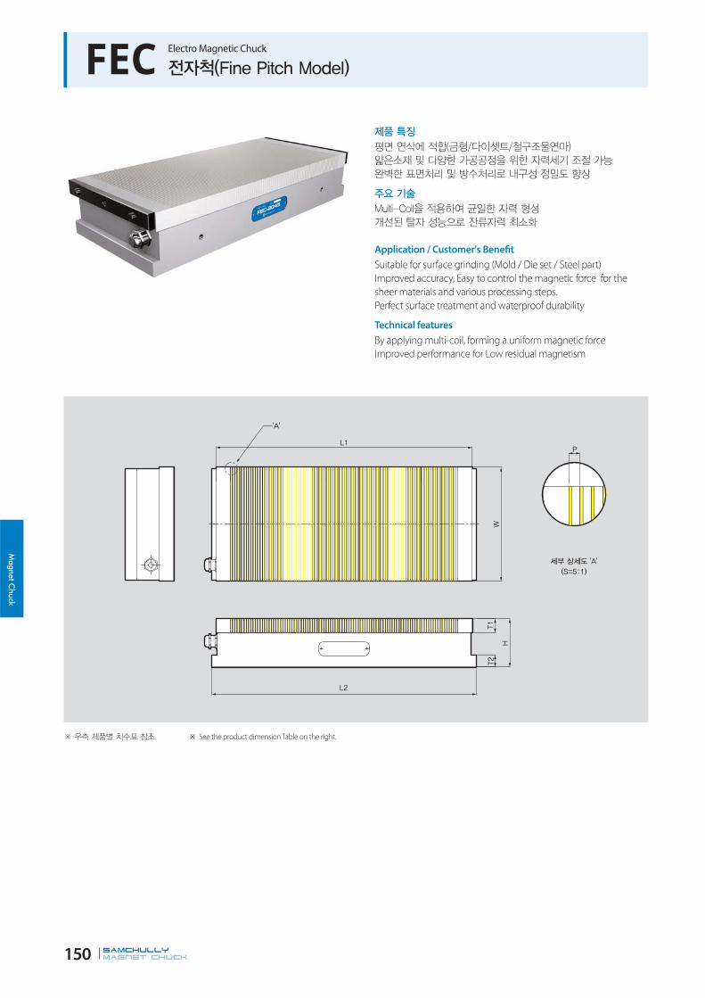
Magnet C
huck
SAMCHULLYmagnet chuck150
FEC Electro Magnetic Chuck
See the product dimension Table on the right.
Application / Customer's Benefit
Suitable for surface grinding (Mold / Die set / Steel part)
Improved accuracy, Easy to control the magnetic force for the
sheer materials and various processing steps.
Perfect surface treatment and waterproof durability
Technical features
By applying multi-coil, forming a uniform magnetic force
Improved performance for Low residual magnetism

Mag
net C
huck
SAMCHULLYmagnet chuck 151
SPECIFICATIONS
FEC-1530 FEC-1535 FEC-1540 FEC-2040 FEC-2045
Pole Pitch 1+3 1+3 1+3 1+3 1+3
Total Length 150 150 150 200 200
Base Width 315 365 415 415 465
Base Height 21 21 21 21 21
Total Height 85 85 85 85 85
Upper Width 300 350 400 400 450
Upper Height 25 25 25 25 25
Power Supply AC 220V AC 220V AC 220V AC 220V AC 220V
Output Voltage DC95 DC95 DC95 DC95 DC95
Weight 25 28 32 42 47
FEC-2050 FEC-2060 FEC-3050 FEC-3060
Pole Pitch 1+3 1+3 1+3 1+3
Total Length 200 200 300 300
Base Width 515 615 515 615
Base Height 21 21 21 21
Total Height 85 85 85 85
Upper Width 500 600 500 600
Upper Height 25 25 25 25
Power Supply AC 220V AC 220V AC 220V AC 220V
Output Voltage DC95 DC95 DC95 DC95
Weight 52 62 88 98
Controller "Neocon-E" is basic components.
Specifications are subject to change without notice.

Magnet C
huck
SAMCHULLYmagnet chuck152
PEC Premium Electro Magnetic Chuck
See the product dimension Table on the right.
Application / Customer's Benefit
Suitable for surface grinding (Mold/Die set/Steel part)
Save the loaded/unloaded time for workpiece
No heat generated
Perfect surface treatment and waterproof for durability
Technical features
Uniform magnetic power by multi-coil
Improved performance for low residual magnetism
Build in magnet to prevent a power failure

Mag
net C
huck
SAMCHULLYmagnet chuck 153
SPECIFICATIONS
PEC-1530 PEC-1535 PEC-1540 PEC-2040 PEC-2045
Pole Pitch 1+3 1+3 1+3 1+3 1+3
Total Length 150 150 150 200 200
Base Width 315 365 415 415 465
Base Height 21 21 21 21 21
Total Height 85 85 85 85 85
Upper Width 300 350 400 400 450
Upper Height 25 25 25 25 25
Power Supply AC 220V AC 220V AC 220V AC 220V AC 220V
Output Voltage DC95 DC95 DC95 DC95 DC95
Weight 25 28 32 42 47
PEC-2050 PEC-2060 PEC-3050 PEC-3060
Pole Pitch 1+3 1+3 1+3 1+3
Total Length 200 200 300 300
Base Width 515 615 515 615
Base Height 21 21 21 21
Total Height 85 85 85 85
Upper Width 500 600 500 600
Upper Height 25 25 25 25
Power Supply AC 220V AC 220V AC 220V AC 220V
Output Voltage DC95 DC95 DC95 DC95
Weight 52 62 88 98
Controller "Neocon-E" is basic components.
Specifications are subject to change without notice.

Magnet C
huck
SAMCHULLYmagnet chuck154
MSC Permanent Magnetic Chuck
See the product dimension Table on the right.
Application / Customer's Benefit
Unnecessary power source
Uniform magnetic power by manual operation
No heat generated
Suitable for grinder, electric discharge machine
Technical features
Fine pitch grinding of small and thin workpieces

Mag
net C
huck
SAMCHULLYmagnet chuck 155
SPECIFICATIONS
MSC-1018 MSC-1325 MSC-1530 MSC-1545 MSC-2040
Pole Pitch 1+3 1+3 1+3 1+3 1+3
Total Length 105 130 150 150 200
Base Width 195 270 320 470 420
Base Height 21 21 21 21 21
Total Height 45 45 45 45 45
Upper Width 175 250 300 450 400
Upper Height 25 25 25 25 25
Weight 7 12 17 25 30
MSC-2050 MSC-2060 MSC-3050 MSC-3060
Pole Pitch 1+3 1+3 1+3 1+3
Total Length 200 200 300 300
Base Width 520 620 520 620
Base Height 21 21 21 21
Total Height 45 45 45 45
Upper Width 500 600 500 600
Upper Height 25 25 25 25
Weight 40 48 60 72
Specifications are subject to change without notice.
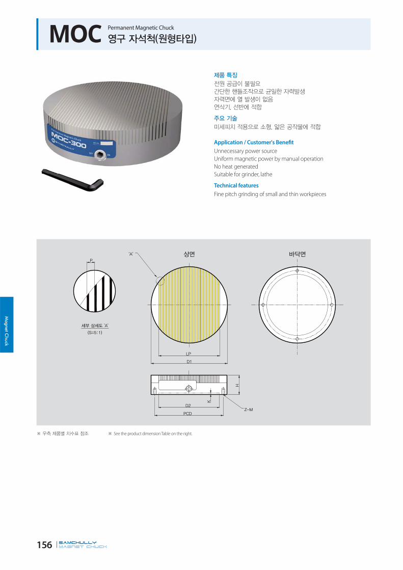
Magnet C
huck
SAMCHULLYmagnet chuck156
MOC Permanent Magnetic Chuck
See the product dimension Table on the right.
Application / Customer's Benefit
Unnecessary power source
Uniform magnetic power by manual operation
No heat generated
Suitable for grinder, lathe
Technical features
Fine pitch grinding of small and thin workpieces

Mag
net C
huck
SAMCHULLYmagnet chuck 157
SPECIFICATIONS
MOC-160 MOC-200 MOC-250 MOC-300
Pole Pitch 1+3 1+3 1+3 1+3
Total Length 160 200 250 300
Pole Pitch Width 120 160 210 260
Total Height 50 50 50 50
Base Width 125 160 220 260
Base Height 4 4 4 4
PCD 140 180 220 260
Z-M 4-M8 4-M8 4-M10 4-M10
Weight 8 12 20 32
Specifications are subject to change without notice.

DRILLING & TAPPING MACHINE
삼천리기계는 터닝센터 그리고 머시닝센터에서의 다양하고 광범위한
머신툴 토탈 솔루션을 제공하는 글로벌 기업입니다.
제조산업의 생산성 향상과 고정밀 가공을 위한 끊임없는 신제품 개발과 기술혁신이야 말로
삼천리기계가 지향하는 미래 가치입니다.
Samchully is the global machine tool's total company which has been supplied various
and wide range of solutions for turning and machining center.we are aiming for the
improvement of productivity and high precision machining to manufacturing industry
through awesome products and technology innovation.
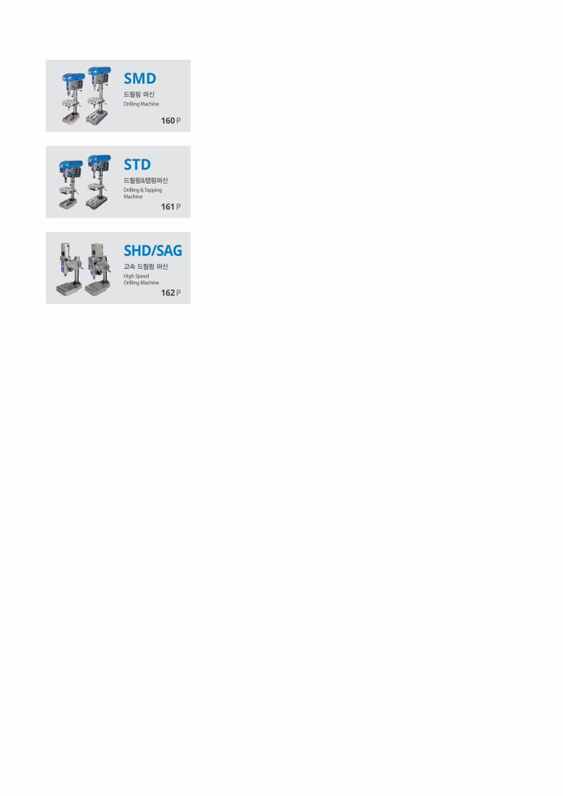
SMD
STD
SHD/SAG
Drilling Machine
Drilling & TappingMachine
High SpeedDrilling Machine
160P
161P
162P

Drilling & Tapping M
achine
SAMCHULLYdrilling tapping machine160
SMD Drilling Machine
Code No. SMD-360 SMD-410
Swing Bx2 360 410
Drilling Capacity [Steel] - Ø3-Ø11 Ø4-Ø16
Drilling Capacity(Cast iron) - Ø3-Ø13 Ø4-Ø19
Max. length between spindle and Table C 357 490
Max. length between spindle and base D 570 700
Stroke [Drill] - 80 100
Stroke [Tap] - - -
Taper - J.T NO.6 M.T NO.2
Column - Ø80 Ø90
Table size [Round] A Ø285 Ø325
Spindle R.PM. - 500/900/1600/2800 480/780/1360/2400
Motor - 0.4KW 4P 0.75KW 4P
Belt Cover size JxK 570x180 665x220
Base size HxG 465x270 600x340
Height F 1012 1230
Weight - 70 100
V-belt - A41x1EA A47x1EA
SPECIFICATIONS & DIMENSIONS
Technical features
Simple speed transmission use V-belt, Quick-set step-speed control Drilling machine

Dril
ling
& Ta
ppin
g M
achi
ne
SAMCHULLYdrilling tapping machine 161
STD Drilling & Tapping Machine
SPECIFICATIONS & DIMENSIONS
Technical features
Quick rotation and reverse rotation tapping.
Code No. STD-360 STD-360 STD-410 STD-430
Bx2 360 360 410 430
- Ø3-Ø11 Ø3-Ø11 Ø4-Ø16 Ø4-Ø20
- Ø3-Ø13 Ø3-Ø13 Ø4-Ø19 Ø4-Ø25
- M10 M10 M12 M16
- M13 M13 M16 M20
C 357 357 490 494
D 562 562 715 720
- 80 80 100 120
- 75 75 95 115
- J.T NO.6 J.T NO.6 M.T NO.2 M.T NO.3
- Ø80 Ø80 Ø90 Ø90
A Ø275 Ø275 Ø325 Ø325
-
210/280/400
560/670/900
1000/1900
210/280/400
560/670/900
1000/1900
125/225/340
400/550/740
1140/1850
100/185/275
335/445/580
870/1390
- 0.4KW 6P 0.4KW 6P 0.75KW 6P 1.5KW 8P
JxK 665x220 665x220 665x220 665x220
HxG 465x270 465x270 600x340 600x340
F 1020 1020 1235 1296
- 90 90 115 135
-A28x2EA
A43x1EA
A28x2EA
A43x1EA
A30x1EA
A32x1EA
A49x1EA
A31x1EA
A32x1EA
A49x1EA

Drilling & Tapping M
achine
SAMCHULLYdrilling tapping machine162
SHD/SAG High Speed Drilling Machine
Technical features
SHD-280 Stepless speed changer due to direct drive.
SAG-280 Belt type, 4-speed.
SHD-280 SAG-280
Swing (Bx2) 280 280
Drilling Capacity Ø0.4-Ø4.0 Ø0.4-Ø4.0
Max. length between spindle and base (C) 180 170
Stroke [Drill] 40 40
Taper J.T #D J.T #D
Spindle R.PM."2,000-12,000
NO-Step vareable"
1 : 12,000
2 : 9000
3 : 6500
4 : 2700
Motor AC220V. 60Hz, 85W AC220V. 60Hz,250w
Weight 29 30
V-belt - 3M265
SPECIFICATIONS & DIMENSIONS
170
B
C170
Dril
ling
& Ta
ppin
g M
achi
ne

CHAMFER MACHINE
삼천리기계는 터닝센터 그리고 머시닝센터에서의 다양하고 광범위한
머신툴 토탈 솔루션을 제공하는 글로벌 기업입니다.
제조산업의 생산성 향상과 고정밀 가공을 위한 끊임없는 신제품 개발과 기술혁신이야 말로
삼천리기계가 지향하는 미래 가치입니다.
Samchully is the global machine tool's total company which has been supplied various
and wide range of solutions for turning and machining center.we are aiming for the
improvement of productivity and high precision machining to manufacturing industry
through awesome products and technology innovation.

CMMulti Functional Chamfering Machine
166P
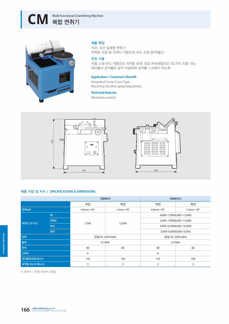
SAMCHULLYChamfer machine166
Cham
fer Machine
CM Multi-functional Chamfering Machine
370
44
2
370
Application / Customer's Benefit
Integrated Linear, Curve Type.
Mounting the drive speed adjustment.
Technical features
Minimizes scratch.
SPECIFICATIONS & DIMENSIONS
CM4015 CM4015-i
4.0mm / 45˚ 1.5mm / 45˚ 4.0mm / 45˚ 1.5mm / 45˚
AL
7,500 12,000
4,000~7,500(6,000~12,000)
STEEL 5,000~7,000(8,000~11,000)
SUS 5,000~6,500(8,000~10,500)
SKD 5,000~6,000(8,000~9,500)
AC 220V 60Hz AC 220V 60Hz
0.75kW 0.75kW
80 80 80 80
X O
150 100 150 100
3 3 3 3

Cha
mfe
r M
achi
ne

ACCESSORIES
삼천리기계는 터닝센터 그리고 머시닝센터에서의 다양하고 광범위한
머신툴 토탈 솔루션을 제공하는 글로벌 기업입니다.
제조산업의 생산성 향상과 고정밀 가공을 위한 끊임없는 신제품 개발과 기술혁신이야 말로
삼천리기계가 지향하는 미래 가치입니다.
Samchully is the global machine tool's total company which has been supplied various
and wide range of solutions for turning and machining center.we are aiming for the
improvement of productivity and high precision machining to manufacturing industry
through awesome products and technology innovation.

Soft JawPower Chuck Soft Jaw
170P
Drill ChuckDrilling MachineAccessories
184P
Hard JawPower Chuck Hard Jaw
172P
T-NutPower Chuck T-Nut
174P
AdaptorPower ChuckAdaptor Plates
176P
QJC JawQuick Jaw ChangeChuck Jaws
178P
TC, FTC JawScroll Chuck Jaws
180P
SC, IC JawScroll Chuck Jaws
181P
Etc.Scroll ChuckAccessories
182P

Accessories
SAMCHULLYaccessories170
Soft Jaw Power Chuck Soft Jaw
Application / Customer's Benefit
Works with HC.
S-14
S-13
S-15
S-11
S-14
S-13
S-15
S-11
See the product dimension Table on the right.

Accessories A
cces
sorie
s
SAMCHULLYaccessories 171
SB04C1 SB05N1 SB06B1 SB08B1 SB10B1 SB12A1 SB12N1 SB15C1
Fig. 2 2 2 2 2 1 1 1
Serration Pitch 1.5x60° 1.5x60° 1.5x60° 1.5x60° 1.5x60° 1.5x60° 1.5x60° 1.5x60°
S-1 48 62 72 95 110 129 111 165
S-2 19 23 31 35 40 50 50 62
S-3 23 25 32 38 42 50 50 66
S-4 8 10 12 14 16 18 21 22
S-5 3 4 5 5 5 5 4 8
S-6 8 12 15 15 30 39 21 37
S-7 15 19 20 25 30 30 30 43
S-8 25 28 37 46 50 60 60 85
S-9 11 13.5 17 19 19 23 25 32
S-10 7 8.5 11 13 13 15 17 21
S-11 15 16.5 20 23 27 30 33 42
S-12 M6x16 M8x20 M10x30 M12x35 M12x35 M14x45 M16x40 M20x60
S-13 - - - - - - - -
S-14 6 5 12 12 15 - - -
S-15 - - - - 20 - - -
Corresponding HCH-04 HS/HC-04,05 HS/HCH/HC-06,MH-206, UR-175
HCH/HC/HS-08,MH-208, UR-210
HCH/HC/HS-10, MH-210, UR-250 HC/HCH-12 HS-12, MH-212
UR-315HCH-15HCH-18
SB15N1 SB15A2 SB18A2 SB32B2 SB32GB SB32SB2 SB40GB SB40SB2
Fig. 1 1 1 1 1 3 3 1
Serration Pitch 1.5x60° 3.0x60° 3.0x60° 3.0x60° - 3.0x60° - 3.0x60°
S-1 135 165 180 160 165 185 270 270
S-2 50 62 65 75 75 75 110 110
S-3 60 66 70 75 83 75 117 110
S-4 25.5 22 25 25.5 12.7 25.5 30 30
S-5 5 8 9 7 13 7.5 13 7.5
S-6 26 30 40 25 21.9 26.8 48.8 32.5
S-7 43 50 60 38 76.2 38.1 76.2 60
S-8 66 85 80 97 - 82 76.2 -
S-9 32 32 32 32 32 32 39 39
S-10 21 21 21 22 22 22 26 26
S-11 39 42 45 54 59 57 90 90
S-12 M20x55 M20x60 M20x60 M20 M20 M20 M24 M24
S-13 - - - - - 82 68.8 117.5
S-14 - - - - 19.025 - 19.025 -
S-15 - - - - - - - 85
Corresponding HC-15, HC-18 MH-218HC/HCH-21,HC/HCH-24,MH-221,224
HCH-32 [Serration]
HC-32[Groove]
HC-32[Serration]
HC-40 [Groove] /50,55,63,70,80
HC-40 [Serration] /50,55,63,70,80
제품 치수 / DIMENSIONS

Accessories
SAMCHULLYaccessories172
Hard Jaw Power Chuck Hard Jaw
H-2
H-14H-4
H-3
H-5
H-1
H-11
H-12
H-7 H-7H-13
H-15
H-9
H-10
19.025
H-6 H-8
H-13
H-7H-7 H-10H-9
H-11
H-11
H-6 H-8H-1
H-3
H-5
H-4
H-2
H-12SERRATION
See the product dimension Table on the right.
Application / Customer's Benefit
Works with HC.

Accessories A
cces
sorie
s
SAMCHULLYaccessories 173
HB04N1 HB06A1 HB08A1 HB10A1 HB12B1 HB12N1 HB15A1 HB15A2
Fig. 2 4 1 1 2 2 1 1
Serration Pitch 1.5x60° 1.5x60° 1.5x60° 1.5x60° 1.5x60° 1.5x60° 1.5x60° 3.0x60°
H-1 53 86 86 99.5 97.5 103 149 149
H-2 23 35 35 40 50 50 62 62
H-3 27.5 51 51 54 55 52 86 86
H-4 10 14 14 16 18 21 22 22
H-5 4 5 5 5 5 4 9 9
H-6 30.5 31 31 43 64.5 62.5 63 63
H-7 14 20 25 30 30 30 43 50
H-8 22.5 18 18 17 33 40.5 34 34
H-9 13.5 19 19 19 22 25 32 32
H-10 8.5 13 13 13 15 17 21 21
H-11 10 12 12 13 20 17 20 20
H-12 M8 M12 M12 M12 M14 M16 M20 M20
H-13 6 18 12 15 18 30 40 40
H-14 - - 12 15 - - 40 40
H-15 - - - - - - - -
Corresponding HS-04, HS-05 "HC/HS-08 MH-208, UR-210"
HC/HCH/HS-08,MH-208, UR-210
HC/HCH/HS-10,MH-210, UR-250 HC/HCH-12 HS-12, MH-212
UR-315HCH-15,HCH-18 MH-218
HB15N1 HB18B2 HB32B2 HB32GB HB32SB2 HB40GB HB40SB2 -
Fig. 1 2 2 3 2 3 2 -
Serration Pitch 1.5x60° 3.0x60° 3.0x60° - 3.0x60° - 3.0x60° -
H-1 149 159.5 150 150 168 223 223 -
H-2 62 80 70 70 70 80 80 -
H-3 86 90 75 83 75 124 117 -
H-4 25.5 25 25.5 25 25.5 30 30 -
H-5 5 9 7 13 7.5 15 8 -
H-6 69 104.5 66 66 89 133 133 -
H-7 43 50 76.2 38.1 38.1 38.1 114.3 -
H-8 27 55 79 79 79 90 90 -
H-9 32 32 32 32 32 39 39 -
H-10 21 21 21 21 21 26 26 -
H-11 20 40 32 32 32 55 55 -
H-12 M20 M20 M20 M20 M20 M24 M24 -
H-13 43 55 - 79 - 83 - -
H-14 38 - - 12.7 - - - -
H-15 - - - 8 - 7 - -
Corresponding HC-15, HC-18HC/HCH-21,HC/HCH-24,MH-221,224
HCH-32[Serration]
HC-32[Groove]
HC-32[Serration]
HC-40[Groove]50,55,63,70,80
HC-40[Serration]50,55,63,70,80 -
제품 치수 / DIMENSIONS

Accessories
SAMCHULLYaccessories174
T-NUT Power Chuck T-Nuts
See the product dimension Table on the right.
Application / Customer's Benefit
Works with HC.

Acc
esso
ries
SAMCHULLYaccessories 175
TN-HCH-04TN-HS-04,
TN-HS-05TN-HC-04 TN-HC-05 TN-HS-06
TN-HCH,
TN-HC-06TN-HS-08
TN-HCH,
TN-HC-08TN-HS-10
TN-HCH,
TN-HC-10
Fig. 1 1 1 1 1 1 1 1 1 1
T-1 24.5 26 28 32 36 36.5 46.5 48 51 55
T-2 11.5 15 15 15 17.5 17.5 20.5 20.5 22.5 22.5
T-3 13.5 15 18 18 18.5 22.5 20.5 25.5 21.5 25.5
T-4 8 10 10 10 12 12 14 14 16 16
T-5 15 14 14 19 20 20 25 25 30 30
T-6 4.5 6 7 6 8.25 7.5 10.5 11 11 11
T-7 9 9.5 12.5 12.5 11 15 12 16 13 16
T-8 M6 M8 M8 M8 M10 M10 M12 M12 M12 M12
T-9 5 5 5 6 8 6 12 8 11 8
T-10 - - - - - - - - - -
T-11 - - - - - - - - - -
Corresponding
HCH
Type of
4” Chuck
HS
Type of
4“, 5” Chuck
HC
Type of
4” Chuck
HC
Type of
5” Chuck
HS/MH/UR
Type of
6”Chuck
HCH/HC
Type of
6” Chuck
HS/MH/UR
Type of
8’’Chuck
HCH/HC
Type of
8" Chuck
HS/MH/UR
Type of
10” Chuck
HCH/HC
Type of
10” Chuck
TN-HS-12TN-HCH,
TN-HC-12
TN-HCH-15,
TN-HCH-18
TN-HC-15,
TN-HC-18TN-MH-218
TN-HCH-21,
TN-HCH-24
TNX-HC-21,
TNX-HC-24TN-HCH-32 TN-HC-32 TN-HC-40
Fig. 1 1 2 1 2 3 3 3 3 3
T-1 55.5 55.5 80 80 80 100 46 35 37 42
T-2 29.5 26.5 33.5 35 33.5 37.5 37.5 35 37.5 42.5
T-3 27.75 33.5 45.5 39 45.5 45 45 39.5 47.5 49.5
T-4 21 18 24 25.5 24 25 25 25.5 25.5 30
T-5 30 30 43 43 50 60 26.5 25 - -
T-6 12 11.5 17 17 17 20 23 - - -
T-7 16.25 20 29 20 29 26 26 20.5 28.5 30.5
T-8 M16 M14 M20 M20 M20 M20 M20 M20 M20 M24
T-9 13 12 11 11 16 11 - - - -
T-10 - - 22 - - 22 - - - .
T-11 - - 7.5 - - 7.5 - - - .
Corresponding
HS/MH
Type of
12” Chuck
HCH/HC
Type of
12” Chuck
HCH
Type of
15”, 18” Chuck
HC
Type of
5", 18" Chuck
MH-218HCH/HCHF-
21,24(S),
MH-221(S)
HC/HCF-21,24
HCH/HCHF-
21,24(H),
MH-221(H)
HCH-32 HC-32 HC-40
DIMENSIONS
Maximum extreme-pressure protection
Exceptional adhesion & cohesion characteristics
Superior friction-reduction properties-protects against friction-related heat & wear
Excellent resistance to water washout & spray off
Reduces maintenance & downtime
Reduces operating temperatures
Extends equipment life.
TNX-HC-21-24, TNX-HC-32 require two T-nuts per jaw.
TNX-HC-40 require three T-nuts per jaw.

Accessories
SAMCHULLYaccessories176
Adaptor Plates Power Chuck Adaptor Plates
Fig. 3 : Plate TypeFig. 2 : Indirect TypeFig. 1 : Direct Type
See the product dimension Table on the right.
Application / Customer's Benefit
Works with HC.

Acc
esso
ries
SAMCHULLYaccessories 177
Fig. Spindle Nose A B C G H Corresponding
AP06A05 1 A2-5 140 15 82.563 104.78 12 HS/HSL/HCH/HC/HCL-06, MH-206, UR-175
APT06A05 1 A2-5 140 15 82.563 104.78 12 HST/HCT/HCLT-06, MHT-206
AP08A06 1 A2-6 170 17 106.375 133.35 13.5 HS/HSL/HCH/HC/HCL-08, MH-208, UR-210
APT08A06 1 A2-6 170 17 106.375 133.35 13.5 HST/HCT/HCLT-08, MHT-208
APF08A06 1 A2-6 170 17 106.375 133.35 13.5 HSF/HCF/HCLF-08, MHF-208
AP10/12A08 1 A2-8 220 18 139.719 171.45 18 HS/HSL/HCH/HC/HCL-10,12, MH-210, UR-250
APT10/12A08 1 A2-8 220 18 139.719 171.45 17 HST/HCT/HCLT-10,12
APF10/12A08 1 A2-8 220 18 139.719 171.45 18 HSF-10,12, HCF/HCLF-12
AP212A08 1 A2-8 300 22 139.719 235 21 MH-212, UR-315
AP212A11 1 A2-11 300 22 196.87 235 21 MH-212
AP15A11 1 A2-11 300 22 196.87 235 21 HCH-15, HC-15,18
APT15A11 1 A2-11 300 22 196.87 235 21 HCHT-15
APF15A11 1 A2-11 300 22 196.87 235 21 HCHF-15, HCF-15,18
AP18A11 1 A2-11 380 22 196.87 235 21 HCH-18
APF18A11 1 A2-11 380 22 196.87 235 21 HCHF-18
AP21/24A15 1 A2-15 380 27 285.775 330.2 24 HCH/HC-21,24, MH-221,224
Fig. Spindle Nose A B C G H J K Corresponding
AP08A05 2 A2-5 170 25 82.563 104.78 12 133.35 M12HS/ HST/ HSF/ HSL/ HCH/ HC/ HCT/ HCF/
HCL/ HCLT/ HCLF-08, MH/ MHT/ MHF-208
AP10/12A06 2 A2-6 220 25 106.375 133.35 13.5 171.45 M16HS/ HST/ HSF/ HSL/ HCH/ HC/ HCT/ HCL/
HCLT-10,12, MH-210, HCF/ HCLF-12
AP15A08 2 A2-8 300 33 139.719 171.45 18 235 M20 HCH/ HCHT/ HCHF-15, HC/HCF-15,18
AP218A15 2 A2-15 380 60 285.775 330.2 24 300 M20 MH-218
AP21/24A11 2 A2-11 380 27 196.87 235 21 330.2 M22 HCH/ HC-21,24,MH-221,224
AP21/24A11 2 A2-11 380 42 196.87 235 22 330.2 M22 HCH/ HCHF/ HC/ HCF-21,24, MH-221,224
AP21/24A11 2 A2-11 380 42 196.87 235 22 330.2 M24 HC/HCF-32, HCH/HCHF/HC-21N,24N
AP21/24A15 2 A2-15 380 42 285.775 330.2 24 330.2 M22 HCH/ HC-21,24, MH-221,224
AP32A15 2 A2-15 380 42 285.775 330.2 26 330.2 M24 HC-32
AP32/40A11 2 A2-11 520 50 196.87 235 22 463.6 M24 HCH-32, HC-40, HC-50
AP32/40A15 2 A2-15 520 42 285.775 330.2 26 463.6 M24 HCH-32, HC-40, HC-50
Fig. Spindle Nose A A-1 B C G H J K Corresponding
AP06A06 3 A2-6 165 140 33 106.375 133.35 14 104.78 M10 HS/ HSL/ HCH/ HC/ HCL-06, MH-206
AP08A08 3 A2-8 210 170 30 139.719 171.45 18 133.35 M12
HS/ HST/ HSF/ HSL/ HCH/ HC/ HCT/
HCF/ HCL/ HCLT/ HCLF-08,
MH/ MHT/ MHF-208
DIMENSIONS

Accessories
SAMCHULLYaccessories178
QJC-Jaw Quick Jaw Change Chuck Jaws
Soft Top Jaws Hard Top Jaws
QSB206 QSB208 QSB210 QSB215
S-1 85 105 125 145
S-2 20 22 30 35
S-3 37.5 40 50 50
S-4 8 10 12 12
S-5 6.5 8.5 8.5 8.5
S-6 17 25 25 31
S-7 32 40 40 54
S-8 36 40 60 60
S-9 15 15 20 20
S-10 9 9 14 14
S-11 28 31 39 34
S-12 M8x20 M8x20 M12x30 M12x40
S-13 18 20 20 26
S-14 3.5 5 5 5
Corresponding QJC-206 QJC-208 QJC-210,QJC-212 QJC-215
SOFT TOP JAWS DIMENSIONS
QHB206 QHB208 QHB210 QHB215
S-1 63 72 90 105
S-2 36 43 55 61
S-3 32.5 38 50 56
S-4 29.5 34.5 46.5 52.5
S-5 20 22 30 36
S-6 8 10 12 12
S-7 17 15 21 23.5
S-8 32 40 40 54
S-9 14 17 29 27.5
S-10 18 20 20 26
S-11 3.5 5 5 5
Corresponding QJC-206 QJC-208 QJC-210,QJC-212 QJC-215
HARD TOP JAWS DIMENSIONS

Acc
esso
ries
SAMCHULLYaccessories 179
Base Jaws Solid Soft Jaws Solid Hard Jaws
QBJ206 QBJ208 QBJ210 QBJ212 QBJ215
S-1 65 85 104 115 125
S-2 32 40 40 40 54
S-3 19 23 26 26 30
S-4 18 20 20 20 26
S-5 20 22 26 32 32
S-6 30 32 40 45 45
S-7 8 10 12 12 12
S-8 2.5 2 3 3 3
S-9 M8 M8 M12 M12 M12
S-10 4.712 4.712 5.498 5.498 5.498
Corresponding QJC-206 QJC-208 QJC-210 QJC-212 QJC-215
BASE JAWS DIMENSIONS
MQSB206 MQSB208 MQSB210 MQSB212 MQSB215
S-1 65 85 104 115 125
S-2 20 22 26 32 32
S-3 55 65 84 90 100
S-4 38.5 48 63 64 74
S-5 4.712 4.712 5.498 5.498 5.498
Corresponding QJC-206 QJC-208 QJC-210 QJC-212 QJC-215
SOLID SOFT JAWS DIMENSIONS
MQHB206 MQHB208 MQHB210 MQHB212 MQHB215
S-1 65 85 104 115 125
S-2 20 22 26 32 32
S-3 55 65 84 90 100
S-4 38.5 48 63 64 74
S-5 4.712 4.712 5.498 5.498 5.498
S-6 7.5 10 14 14 45
S-7 7.5 10 14 14 15
Corresponding QJC-206 QJC-208 QJC-210 QJC-212 QJC-215
SOLID HARD JAWS DIMENSIONS

Accessories
SAMCHULLYaccessories180
TC, FTC-Jaw Scroll Chuck Jaws
TC / FTC Soft Jaws TC / FTC Hard Jaws TC / FTC Base Jaws
TC/FTC SOFT JAWS DIMENSIONS
TC/FTC HARD JAWS DIMENSIONS
TC/FTC BASE JAWS DIMENSIONS
TC-190 TC-230 TC-273 TC-310 FTC-460 FTC-535 FTC-610
A 88 100 110 125 140 150 150
B 32 32 35 40 50 50 50
C 41 44 48.5 49.5 71.5 76.5 76.5
D-1 22.225 26.99 26.99 31.75 38.1 38.1 38.1
D-2 22.225 26.99 26.99 31.75 38.1 38.1 38.1
E 40 45 51 58 63.5 67.5 67.5
F 48 55 59 67 76.5 82.5 82.5
G 3 3 3 3 5.8 6 6
H 12.68 19.03 19.03 19.03 19.03 19.03 19.03
J 17 19 19 19 32 32 32
K 11 12.7 12.7 12.7 22 22 22
L 7.94 12.7 12.7 12.7 12.7 12.7 12.7
M 7 7 7 7 - - -
TC-190 TC-230 TC-273 TC-310 FTC-450 FTC-535 FTC-610
A 80.5 90.5 103.5 115.5 130 130 130
B 28 32 35 40 50 50 50
C1 10 12 14 15 17 17 17
C2 10 12 14 15 17 17 17
C3 41 48 52 54 76.8 76.8 76.8
D1 22.225 26.99 26.99 31.75 38.1 38.1 38.1
D2 22.225 26.99 26.99 31.75 38.1 38.1 38.1
E 40.5 45.5 52 58 63.5 63.5 63.5
F 40 45 51.5 57.5 66.5 66.5 66.5
G 3 3 3 3 5.8 5.8 5.8
H 12.68 19.03 19.03 19.03 19.025 19.025 19.025
ΦJ 17 19 19 19 32 32 32
ΦK 11 13 13 13 22 22 22
ΦL 7.9 12.7 12.7 12.7 - - -
N1 21.5 23.5 31.5 30.5 52 52 52
N2 29 33 34 40 35 35 35
TC-190 TC-230 TC-273 TC-310 FTC-460 FTC-535 FTC-610
A 75 87 98 111 165 177 205
B 28 28 28 32 45 50 50
C 34 38 40 42.5 54 57 60
D-1 22.225 26.99 26.99 31.75 38.1 38.1 38.1
D-2 22.225 26.99 26.99 31.75 38.1 38.1 38.1
E 35.5 42.5 47 54 - - -
F 39.5 44.5 51 57 66.5 66.5 66.5
G 2-M10 2-M12 2-M12 2-M12 4-M20 4-M20 5-M20
H 12.68 19.03 19.03 19.03 2-19.025 2-19.025 2-19.025
J 15 15 15 17.2 27 30 30
K 7.95 12.7 12.7 12.7 - - -
L 3.5 3.5 3.5 3.5 - - -
M 6.5 6.5 6.5 6.5 9.3 9.3 9.3

Acc
esso
ries
SAMCHULLYaccessories 181
SC, IC-Jaw Scroll Chuck Jaws
SC Jaws(Internal) IC JawsSC Jaws(External)
SC JAWS DIMENSIONS
IC JAWS DIMENSIONS
SC-85 SC-110 SC-130 SC-165 SC-190 SC-230 SC-273 SC-310 SC-355 SC-405
L1 35 42 50 65 75 85 98 110 133 133
L2 11 13 15 20 23 26 30 35 44 44
L3 10 13 15 22 25 28 33 35 42 42
L4 29 34.5 40 46.5 55.5 64.5 69.5 82.5 101 101
L5 26.5 31 36 42 50.5 59.5 64 76 94.5 94.5
L6 16 19 21 27 30 33 38 43 53 53
L7 10 13 15 22 25 28 33 35 42 42
B1 11 14 16 19 22 24 28 30 35 35
B2 5.7 7.5 7.2 9.2 11.2 13.2 15 15 19 19
B3 4.7 6.2 7.7 8.2 9.7 11.2 11.2 13.4 14 14
B4 6.55 6.55 8.2 8.13 9.74 11.38 11.38 16.12 16.2 16.2
B5 6 7 8 10 12 14 15 16 21 21
B6 6 4.3 7.4 10 12 14 15 16 22 22
K1 17.75 21.05 23.4 25.07 30.06 35.04 40.02 45.08 62.98 62.98
R 7.5 11 15 20 25 30 37 43 43 43
D1 1 1.5 1.5 2 2 3 3 4 4 4
IC-08 IC-10 IC-12 IC-14 IC-16 IC-18 IC-20 IC-24 IC-28 IC-32
L1 75 90 100 110 120 130 140 160 160 200
L2 44 54 60 67 73.5 80 85 99 100 120
L3 21 26 28 31 33.5 37 40 46 47 55
L4 55.5 61.5 70.5 75.5 84 89 106 116.4 111 138
L5 12 14 16 18 20 22 24 28.2 28 30
L6 12 14 16 18 20 22 24 28.2 29 30
L7 30 30 35 35 40 40 45 50 50 60
B1 16 16 19 19 22.5 22.5 27.5 31 30 40
B2 10.3 10.3 11.5 11.5 11.5 11.5 16.4 16.4 15.3 20
B3 10 10 13.6 14.6 15 15 16 18 20 34
K1 30 35 40 45 50 55 60 70 70 89
Threads/inch 5/inch 5/inch 4/inch 4/inch 4/inch 4/inch 3.5/inch 3.5/inch 4/inch 6.0 mm

Accessories
SAMCHULLYaccessories182
Accessories Scroll Chuck Accessories
SC-85 SC-110 SC-130 SC-165 SC-190 SC-230 SC-273 SC-310 SC-355
ΦD1
base length 60 80 100 130 155 190 230 260 300
tollerance-0.021 -0.021 -0.025 -0.028 -0.028 -0.033 -0.033 -0.036 -0.036
-0.002 -0.002 -0.003 -0.003 -0.003 -0.004 -0.004 -0.004 -0.004
ΦD2base length 73 95 115 147 172 210 250 285 328
tollerance ±0.2 ±0.2 ±0.2 ±0.2 ±0.2 ±0.2 ±0.2 ±0.3 ±0.3
ΦD3 88 115 135 170 195 235 275 310 355
L1 3 4 4 4.5 4.5 5.5 5.5 6.5 6.5
L2 10 12 12 15 18 20 20 22 26
Φd 6.6 9 11 11 13 13 13 13 13
SC ADAPTOR DIMENSIONS
IC STOPPER DIMENSIONS
IC-08 IC-10 IC-12 IC-14 IC-16 IC-18 IC-20 IC-24 IC-28 IC-32
L1 42 45 51 49 55 60 53 59 57.5 59
ΦD1 26 26 30 30 34 34 35 38 38 44
ΦD2 14.5 14.5 16.5 16.5 18.5 18.5 19.5 20.5 23 27.5
B1 14 14 16 16 18 18 20 20 18 24
IC Screw Bar IC Stopper
IC SCREW BAR DIMENSIONS
IC-08 IC-10 IC-12 IC-14 IC-16 IC-18 IC-20 IC-24 IC-28 IC-32
L1 70 91.5 111 130 149 169 189 233 299 330
L2 41 58 73 85.5 108.5 123.5 137 162 193 216
L3 14 14 16 16 18 18 20 20 18 24
L4 15 19.5 22 28.5 22.5 27.5 32 51 68 90
ΦD1 26 26 30 30 34 34 35 38 38 44
ΦD2 14 14 16 16 18 18 19 20 22 28
B1 10 10 12 12 14 14 14 14 14 19
Thread / inch
5/inch 5/inch 4/inch 4/inch 4/inch 4/inch 3.5/inch 3.5/inch 4/inch 6/inch

Acc
esso
ries
SAMCHULLYaccessories 183
SC, FTC, SL, IC HANDLE DIMENSIONS
SC, FTC, IC MOUNTING BOLT DIMENSIONS
Scroll Chuck Mounting Bolts(SC Type) Scroll Chuck Mounting Bolts(IC Type)Scroll Chuck Handles
SC-85 SC-110 SC-130 SC-165 SC-190 SC-230 SC-273 SC-310 SC-355 SC-405
L1 65 70 75 120 160 160 160 200 200 170
L2 110 140 170 210 240 290 330 390 390 450
B1 7 8 8 10 11 12 12 14 14 15
B2 10 11 11 13 14 15 15 18 18 20
ØD1 15 17 20 20 20 22 22 26 26 26
SC-85 SC-110 SC-130 SC-165 SC-190 SC-230 SC-273 SC-310 SC-355
Bolt size M6xP1.0 M8xP1.25 M8xP1.25 M10xP1.5 M10xP1.5 M12xP1.75 M12xP1.75 M12xP1.75 M12xP1.75
QTR 3 3 3 3 3 3 3 3 6
L1 22 25 25 32 36 40 40 45 50
L2 18 20 20 26 26 30 30 30 30
ØB1 10 13 13 17 17 19 19 19 19
FTC-460 FTC-535 FTC-610 SL-08 SL-10 SL-12
L1 205 230 230 200 240 280
L2 500 500 500 240 270 320
B1 17 6*-22 6*-22 11 12 14
B2 20 26 26 16 16 18
ØD1 25 30 30 20 22 26
FTC-460 FTC-535 FTC-610
Bolt size M16xP125 M20xP140 M20xP140
QTR 6 6 6
L1 125 140 140
L2 38 52 52
ØB1 24 30 30
IC-08 IC-10 IC-12 IC-14 IC-16 IC-18 IC-20 IC-24 IC-28 IC-32
L1 130 150 170 170 220 220 220 230 300 300
L2 200 250 300 350 400 400 450 500 500 500
B1 10 10 12 12 14 14 14 14 14 19
B2 14 14 17 17 19 19 20 20 20 20
ØD1 15 18 19 19 22 22 22 25 28 35
IC-08 IC-10 IC-12 IC-14 IC-16 IC-18 IC-20 IC-24 IC-28 IC-32
Bolt size M12xP1.75 M12xP1.75 M12xP1.75 M12xP1.75 M16xP2.0 M16xP2.0 M16xP2.0 M20xP2.5 M20xP2.5 M20xP2.5
QTR 4 4 4 4 4 4 4 4 8 8
L1 60 85 100 100 110 110 120 135 120 130
L2 35 40 55 55 60 60 60 70 54 54
ØB1 10 10 10 10 14 14 14 17 17 17

Accessories A
cces
sorie
s
SAMCHULLYaccessories184
Drill Chuck제품 특징KS & JIS 표준형으로 제작. 오랜시간 사용해도 높은 정밀도 유지
Drilling Machine Accessories
드릴 척
Application / Customer’s BenefitManufactured according to KS & JIS standards. Guaranteed high precision and durability
4MG 13MG 16MG 19MG드릴 사용범위 0.4-4.0 1.2-13 1.0-16 1.0-19테이퍼 형식 A JT#D JT#6 JT#6 JT#3
길이 B 42.5 87.3 94.5 115길이 C 33 68 77.5 92
Ø D 25.5 52.5 57 68.5Ø E 21.5 45 - -Ø F 17.5 38 41.5 49.5Ø G 8.5 17.17 17.17 20.59
중량 gf 95 770 - -
공작기계용 치수 및 사양 / HEAVY DUTY TYPES DIMENSIONS & SPECIFICATIONS
6.5EL 10EL 13EL드릴 사용범위 0.5-6.5 0.8-10 1.2-13테이퍼 형식 A JT#1 JT#2 SHORT JT#6
길이 B 47.5 61 79.5길이 C 37 51 67
Ø D 32 37 46Ø E 27 29.6 39Ø F 22 26 33Ø G 9.754 13.94 17.17
중량 gf 170 330 540
휴대전기용 치수 및 사양 / LIGHT DUTY TYPES DIMENSIONS & SPECIFICATIONS
6.5SL 10SL 13SL드릴 사용범위 0.5-6.5 0.8-10 1.2-13테이퍼 형식 A 3/8-24UNF 1/2-20UNF 1/2-20 UNF
길이 B 47.5 61 79.5길이 C 37 51 67
Ø D 32 37 46Ø E 27 29.6 39Ø F 22 26 33Ø G - - -
중량 gf 170 330 540
나사체결형 치수 및 사양 / THREAD MOUNTED TYPES DIMENSIONS & SPECIFICATIONS
※ 공통 부속품(Standard Accessories) : Handle 1ea

Acc
esso
ries

AMERICA EUROPE & AFRICAASIA & OCEANIA
OVERSEAS SALES하루가 다르게 변화하는 세계 공작기계 시장에서 삼천리기계는
보다 창의적인 제품을 속속 개발해 나가고 있습니다.
“모방기술이 아닌 창조기술”을 최고의 가치관으로 삼으며
기계 기술자들에게 보다 큰 감동을 줄 수 있는 혁신적인 제품 개발을 위한
삼천리기계의 끝없는 도전은 계속 될 것입니다.
57 09 12Distribution Partners Distribution Partners Distribution Partners
Samchully Global NetworkOverseas Sales & Service Network
KOREA HEAD OFFICESamchully Machinery Co., Ltd. 99, Namdong-daero, Namdong-gu, Incheon, KoreaTel. +82-32-899-8965Fax. +82-32-721-7607E-mail. [email protected]. www.samchully.com
USA OFFICESamchully Workholding, Inc.20472 Crescent Bay Dr., Ste 108Lake Forest, CA 92630Tel. +1 (949) 727 3001Fax. +1 (949) 727-7070E-mail: [email protected]: www.samchully.com
AMERICABRAZIL Cantena Ltda.CNPJ 04.633.809/0001.01Rua Pastor Oswaldo Hesse, 147989015-100 Blumenau, SC BrazilTel. +55 47 3035 3606Fax. +55 47 3035 3606E-mail. [email protected]. www.cantena.com.br
OCEANIANEWZEALAND Global Machine Tools Limited 55e Richard Pearse Dr., Airport Oaks, Auckland, New ZealandTel. 64-9-275-5111Fax. 64-9-275-0045E-mail. [email protected]. www.gmtools.co.nz
AUSTRALIA C.N.C. Engineering Sales & Services Unit 2/9-11 Cullen Place, Smithfield, Nsw 2164 AustraliaTel. 61-2-9725-5100Fax. 61-2-9609-6296E-mail. [email protected]. www.cnceng.au
ASIACHINA Hangzhou Zezheng Machinery Co.,Ltd.(Hangzhou)1-2-401 Room, Yinlongwan, 351# Sanjiang Road, Wenyan Zhen, Xiaoshan District, HangzhouTel. + 86-571-87389802 / M.P. + 86-13454196518Fax. + 86-571-87389803 E-mail. [email protected], [email protected] Web. www.zezhengcnc.com
INDIA Sri Bhrama Sakthi EngineersPlot No.33, S.F.No:233/2B, Sri Mahalakshmi Puram,N.G.G.O.Colony, Ashokapuram,Coimbatore-641022, INDIATel. 99655-85701, 7373785701E-mail. [email protected]
INDONESIA Gerfa Manunggal Teknindo Komplek Bekasi Mas Blok A No. 20 Jl. Jend. A. YaniBekasi 17141, INDONESIATel. +62-21-8896-6060Fax. +62-21-884-2927E-mail. [email protected]
SINGAPORE Penta-ventura Pte. Ltd. 51 Bukik Batok Crescent , #01-10 Unity Centre SINGAPORE 658077Tel. 65-6316-4111Fax. 65-6316-4222E-mail. [email protected]. www.penta-ventura.com.sg
THAILAND Win Win Co., Ltd. 7/282 Moo 6, Baanmai, Pakkred, Nonthaburi 11120 THAILANDTel. +66-2573 7933-5Fax. +66-2573-7898E-mail. [email protected]. www.winwinthailand.com
TURKEY FORM MAKINA SERIFALI MAH. HATTAT SOK. NO:45 KAT:1UMRANIYE / ISTANBUL / TURKEYTel. +90216-526-51-62Fax. +90216-526-51-63E-mail. [email protected]
TURKEY MEGA YATRIMIstanbul End. Ve. Tic. Serbest BolgesiParsel No: B5, 34940 Tuzla, Istanbul, TurkeyTel. +90 (216) 428 54 41E-mail. [email protected]
AFRICASOUTH AFRICA Retecon (Pty) Ltd. P.O. Box 1472, Kempton Park, 1620, Republic of South AfricaTel. 27-11-394-2810 / Fax. 27-11-394-2471E-mail. [email protected]
EUROPECZECH Repbulic Tecnotrade Obrabeci Stroje s.r.o. Blanenska 1578, 664 34 Kurim, Czech RepublicTel. 420 541-263-636Fax. 420 541-263-637E-mail. [email protected]. www.tecnotrade.cz
ENGLAND Thame Workholding Co., Ltd.Field End, Thame RoadLong Crendon, Aylesbury BucksEngland HP189EJTel. +44 (0) 1844 208050E-mail. [email protected]
ESTONIA Duroc Machine ToolVõru 47e, 50111 Tartu, EstoniaTel. +372 517 0461Fax. +372 736 2264E-mail. [email protected]. www.duroc.com/machinetool/ee/et.aspx
FINLAND Nurminen Tools Oy Vanha Vantontie 2, 21110 Naantali, FINLAND Tel. +358 2 438 9668 Fax. +358 2 438 9669E-mail. [email protected]. www.nurminentools.fi
FRANCE Doga ZA Pariwest-8, avenue Gutenberg -BP53-F78311,maurepas cedex, FRANCETel. +33-6-8580-6035Fax. +33-1-3066-9199E-mail. [email protected]. www.doga.frHUNGARY Grantool KFTGesztenyefa street 4, 9027 Gyor, HungaryTel. +36-9652-8091 / Fax. 36-9652-8092E-mail. [email protected]. www.toolontool.hu
ITALY Prymark SrlVia Vittorio Venteo N. 72/A28041 Arona, (NO) ItalyTel. +39-02-8719-8792E-mail. [email protected]
LATVIA Duroc Machine Tool SiaTilta Street 12 k.2, Riga, Latvia LV-1005Tel. +371-67-355-175 / Fax. +371-67-355-176
E-mail. [email protected]. www.duroc.com/machinetool/lv/lv.aspx
NETHERLAND Spantech Opspansystemen De Glazenmaker 76, 5506EP Veldhoven, NETHERLANDTel. +31-40-230-0222Fax. +31-40-230-0010E-mail. [email protected]. www.spantech.nl
POLAND BETA P.H.U. s.c. Gorzycka 1, 63-400 Ostrów Wielkopolski POLANDTel. +48 62 591-48-10Fax. +48 62 591-48-13E-mail. [email protected]. www.beta.ostrowwlkp.pl
RUSSIA Llc Ads GroupRF, Moscow, ul. Pokrovka, 43/7, RussiaTel. +7 495 916 39 89Fax. +7 495 916 39 89E.mail. [email protected]
RUSSIA Osnastikul.Verh.Maslovka d.2, p.2127083 Moscow, RussiaTel. +7 499 390 93 37Fax. +7 499 390 93 37E-mail. [email protected]
RUSSIA Rosna Engineering Nt LlcRUSSIA, Saint-Petersburg 19029pr: Obuhovskoy Oborony 51Letter “k” office 205 business center “Prinevskuy”Tel. +7-822-677-37-31Fax. +7-822-677-37-31E-mail. [email protected]. www.rosna.spb.ru
PORTUGAL DeibarZona Ind Roligo, Santa Maria da Feira, Aveiro4520-109 Espargo, PortugalTel. +351 256 330 222E-mail. [email protected]. www.deibar.com
ROMANIA Ro-Mega Trade250 Basarabia Bvd, Simtex BuildingDistric 3, Bucharest, 03035, RomaniaTel. +40 (21) 255 25 08Fax: +40 (21) 255 25 09E-mail: [email protected]. www.romega.roSWEDEN Chuckteknik ABFinjaryd 2519, SE-282 91 Tyringe, SwedenTel. +46 40 12 33 44Fax. +46 70 565 07 33E-mail. [email protected]. www.chuckteknik.com

AMERICA EUROPE & AFRICAASIA & OCEANIA
OVERSEAS SALES하루가 다르게 변화하는 세계 공작기계 시장에서 삼천리기계는
보다 창의적인 제품을 속속 개발해 나가고 있습니다.
“모방기술이 아닌 창조기술”을 최고의 가치관으로 삼으며
기계 기술자들에게 보다 큰 감동을 줄 수 있는 혁신적인 제품 개발을 위한
삼천리기계의 끝없는 도전은 계속 될 것입니다.
57 09 12Distribution Partners Distribution Partners Distribution Partners