Embed Size (px)
Citation preview

MACHINE DRAWING
SYLLABUSSection AIntroduction graphic language, classification of drawing, principle of drawing, IS codes for machine drawing, lines, scales, section dimensioning, standard abbreviation, – Limits , fits and Tolerance ( Dimensional and Geometrical tolerance ) , Surface finish, Gears : Gear terminology, I.S. convention representation of assembly of spur gears, helical gears, bevel gears , worm and worm wheel.Section BOrthographic projections: principle of first and third angle projection, orthographic views from isometric views of machine parts / components. Drawing of sectional views:- Coupling, Crankshaft, Pulley, Piston and Connecting rod, Cotter and Knuckle joint. Riveted Joint and Welded Joint.

SYLLABUS
Free hand sketching: Need for free hand sketching of standard parts and simple machines components.
Section CAssembly drawing with sectioning and bill of materials from given detailed drawings of assemblies: Lathe Tail stock, Machine vice, Pedestal bearing
Section DAssembly drawing with sectioning and bill of materials from given detailed drawings of assemblies Steam stop valve, Stuffing box, Drill jigs and Milling fixture.

Introduction- Graphic Language
• Engineering drawing has its origin sometime in 500BC in the regime of King Pharos of Egypt whensymbols were used to convey the ideas amongpeople.
• Irrespective of language barriers, the drawings canbe effectively used in other countries, in addition tothe country where they are prepared.
• Thus, the engineering drawing is the universallanguage of all engineers.

Classification of Drawing
• Machine Drawing-
- Pertaining to machine parts or components.
- presented through a number of orthographic views.
- Size & shape of component is fully understood.

• Production Drawing –
- Referred as working drawing.
- Should furnish all dimensions, limits & special finishing processes such as heat treatment, honing, lapping, surface finish, etc.
- Title should also mention the material used for the product, number of parts required.

• Part Drawing-- Detailed drawing of a
component to facilitate its manufacture.
- Follows principles of orthographic projection
• Assembly Drawing-- A drawing that shows the
various parts of a machine in their correct working locations.

Principle of Drawing
To provide the correct information about drawings to all concerned people, the drawing must be prepared, following certain standard practices, as recommended by Bureau of Indian Standards (BIS).
• Sheet Size- For a reference size A0
having a surface area of 1
X = 841 mm and Y = 1189 mm.

• Designation of Sizes-

• Title Block –
(i) Title of the drawing(ii) Sheet number(iii) Scale(iv) Symbol, denoting the method of projection(v) Name of the firm / institute(vi) Initials of staff drawn, checked and approved.

• Borders & Frames –Minimum 20 mm for size A0 & A1.
Minimum 10 mm for size A2, A3, A4.
• Centering Marks
• Metric reference
graduation
• Grid reference
system
• Trimming mark

Scales• The various types of scales used in machine drawing are
1. Full scale 1:1
2. Reduced scale 1:X
3. Enlarged scale X:1
The standard scales are given in Table

Types of lines
& their
applications

Applications of Lines

Dimensioning1. As far as possible, dimensions should be placed outside the
view.
2. Should be taken from visible outlines, not from hidden lines.
3. Dimensioning to a centre line should be avoided exceptwhen the centre line passes through the centre of a hole.
4. Each feature should be dimensioned only once in a drawing.
5. Placed on the view or section that relates most clearly to thecorresponding features.
6. Each drawing should use the same unit for all dimensions,but without showing unit symbol.
7. Minimum dimensions should be placed to define a wholepart.
8. No features of a part should be defined by more than onedimension in any one direction.

Elements of Dimensioning1. Dimension line — It is a thin continuous line terminated by arrowheads
touching the outlines, extension lines or centre lines.
2. Extension line (Projection line) — It is a thin line drawn outside and along theoutline. There should be a gap of about 1 mm between the extension line and the outline.
3. Leader line —One end of the leader terminates either in an arrowhead or a dot.The arrowhead touches the outline, while the dot is placed within the outline of the object. The other end of the leader is terminated at a horizontal line
4. Arrowhead — An arrowhead is placed at each end of a dimension line. Itspointed end touches an outline, an extension line or a centre line. The length of arrowhead should be about three times its maximum width. The triangle of the arrow should be completely filled in.

Methods of indicating Dimensions
1. Aligned system, and2. Unidirectional system.
1. Aligned system — In the aligned system, the dimensions areplaced above the dimension lines and may be read eitherfrom the bottom or from the right side of the drawing
2. Unidirectional system — In the unidirectional system, alldimensions are placed with respect to the bottom of thedrawing, irrespective of the disposition of the dimensionline. In the system, the dimension lines are broken to inserttheir dimensions . This system is preferred for big drawingsspecially when it is not convenient to read the dimensionfrom the right side or any other direction.

Standard Abbreviation


Limits , Fits and Tolerance
• The system in which a variation in dimensions is accepted iscalled the limit system.
• The allowable deviations are called tolerances.
• The relationships between the mating parts are called fits.

Limits• The two extreme permissible sizes between which the actual
size is contained are called limits.
• The maximum size is called the upper limit and the minimumsize is called the lower limit.
• Tolerance is denoted by two symbols, a letter symbol and anumber symbol, called the grade.
• It is the difference between lower and upper deviation.
Tolerances

• Graphicalillustration oftolerance zones

Method of placing limit dimensions
Method 1

Method 2

Method 3

Types of Fits1. Clearance Fit –
It is a fit that gives a clearance between the two mating parts.

Types of Fits2. Transition Fit –
This fit may result in either an interference or a clearance, depending upon the actual values of the tolerance of individual parts.

Types of Fits3. Interference Fit -
If the difference between the hole and shaft sizes is negative before assembly; an interference fit is obtained.

Schematic Representation of Fits

Surface finishThe geometrical characteristics of a surface include,
1. Macro-deviations,
2. Surface waviness, and
3. Micro-irregularities.
The surface roughness is evaluated by the height, Rt and mean roughness index Ra of the micro-irregularities.

Equivalent Surface Roughness Symbols

Indication of Surface Roughness

Indication of Surface Roughness


Gears• Gears are machine elements, which are used for power transmission
between shafts, separated by small distance.
• While two gears are meshing, the teeth of one gear enter the spaces ofthe other. Thus, the drive is positive and when one gear rotates, the otheralso rotates; transmitting power from one shaft to the other.

Gear Terminology

• Pitch Circle – Outlines of imaginary smooth rollers or fictiondiscs in every pair of mating gears.
• Pitch Diameter – Diameter of pitch circle (P.C.D.)
• Root Diameter – Diameter at the bottom of tooth space.
• Addendum – Height from pitch circle to the tip of the tooth.
• Dedendum – Depth of tooth space below pitch circle.(addendum + clearance)
• Circular Pitch (C.P.) – Length of arc of pitch circle betweensimilar faces of successive teeth.
• Diametral Pitch (D.P.) – Number of teeth divided by pitchdiameter.
• Module (m)- Pitch diameter divided by number of teeth.
• Circular Tooth Thickness – Length of arc of the pitch circlebetween opposite faces of same tooth (0.5 C.P.)

• Base Circle Diameter – Diameter of circle from whichinvolute is generated.
• Line of Action – Common tangent to the two base circles,which passes through the pitch point of a pair of matinggears.
• Pressure Angle- Acute angle formed between the line ofaction and common tangent to the two pitch circles, whichpasses through the pitch point.
• Tooth Fillet – Rounded corner at the bottom of tooth space.
• Centre Distance – Distance between centers of a pair ofmating gears and is equal to sum of the radii of pitch circles ofthe two gears.
• Pitch Point – Point of contact between the pitch circles oftwo gears in mesh & lies on the line joining their centers.

• Tooth face
• Tooth flank
• Crest of tooth
• Root of tooth
• Whole depth
• Working depth
• Addendum circle
• Dedendum / root circle
• Chordal pitch

Gear Calculation
• Circular Pitch = Circumference of P.C.D. / No. of teeth
= P.C.D. x π / No. of teeth
C.P. = P.C.D. x π / N
• Diametral Pitch = No. of teeth / Pitch Circle Diameter
= N / P.C.D.
• C.P. x D.P. = π
C.P. = π / D.P. And D.P. = π / C.P.
• Metric Module , m = Pitch Circle Diameter / No. of teeth
= P.C.D. / N
= 1 / D.P.
C.P. = π / D.P. = π x m

Outside Diameter = Pitch diameter + 2xAddendum
Root Diameter = Pitch diameter - 2xDedendum
Clearance = Dedendum – Addendum
Tooth thickness = C.P. / 2
Addendum = 1 / D.P. = C.P. / π = m
Clearance = C.P. / 20 = (π/D.P.) x (1/20) = 0.157 x m
Pressure angle, θ = 14.5 or 20 degree
Base circle diameter, B.C.D. = P.C.D. x Cos θ
Involute gears will work correctly together if they have the same pressure angle and diametral pitch.
Gear Calculation


Spur Gear
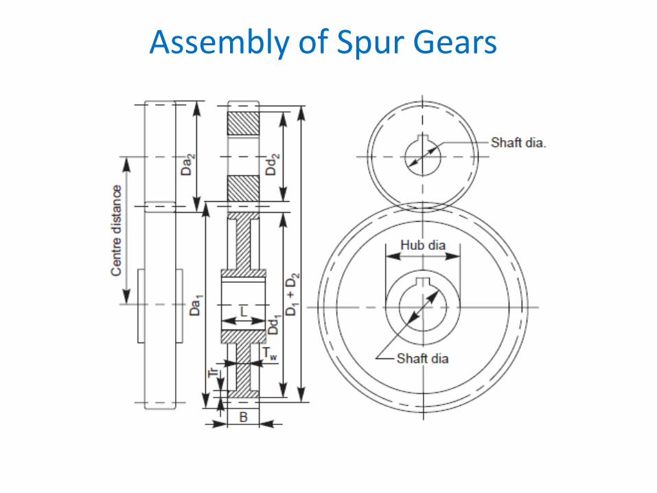
Assembly of Spur Gears

Assembly of Helical Gears

Assembly of Bevel Gears

Assembly of Worm & Worm Wheel