Embed Size (px)
Citation preview
Synchronous Machines
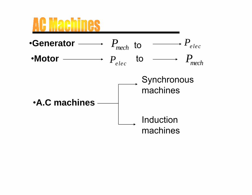
•Generator•Motor
Pelec Pmech toP to P hMotor
Synchronous
Pelec to Pmech
•A.C machinesmachines
Induction machines
Synchronous MachinesSynchronous Machines
• Synchronous generators or alternators are used to convert y gmechanical power derived from steam, gas, or hydraulic-turbine to ac electric power
S h h i f l i l• Synchronous generators are the primary source of electrical energy we consume today
• Large ac power networks rely almost exclusively on synchronous• Large ac power networks rely almost exclusively on synchronous generators
• Synchronous motors are built in large units compare to induction y g pmotors (Induction motors are cheaper for smaller ratings) and used for constant speed industrial drives
Construction
B i t f h tBasic parts of a synchronous generator:
• Rotor - dc excited winding St t 3 h i di i hi h th f i t d• Stator - 3-phase winding in which the ac emf is generated
The manner in which the active parts of a synchronous p ymachine are cooled determines its overall physical size and structure

Types of Synchronous MachineTypes of Synchronous Machine
According to the arrangement of the fieldand armature windings synchronousand armature windings, synchronousmachines may be classified as rotating-armature type or rotating field typearmature type or rotating-field type.
Rotating-Armature Type
The armature winding is on the rotor and the fieldThe armature winding is on the rotor and the fieldsystem is on the stator. The generated current isbrought out to the load via three (or four) slip-rings. Insulation problems, and the difficultyinvolved in transmitting large currents via theb h li it th i t t dbrushes, limit the maximum power output andthe generated electromagnetic field (emf). Thistype is only used in small units and its maintype is only used in small units, and its mainapplication is as the main exciter in largealternators with brushless excitation systems.y
Rotating field typeRotating field type
The armature winding is on the stator andThe armature winding is on the stator andthe field system is on the rotor. Fieldcurrent is supplied from the exciter via twoppslip-rings, while the armature current isdirectly supplied to the load. This type is
l d i ll i hi hemployed universally since very highpower can be delivered. Unless otherwisestated the subsequent discussion refersstated, the subsequent discussion refersspecifically to rotating-field typesynchronous machinessynchronous machines
a
b’ c’N
ab cN
Ifb’
a’c’
bcS
Pelec
c
bca’
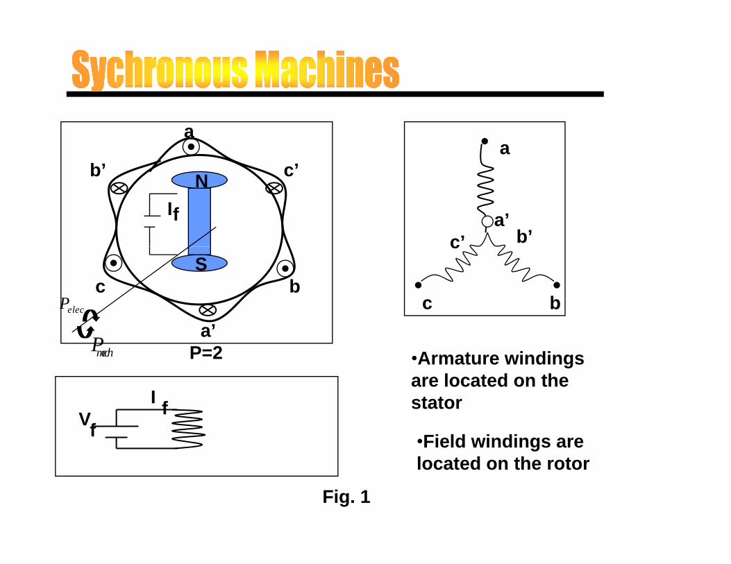
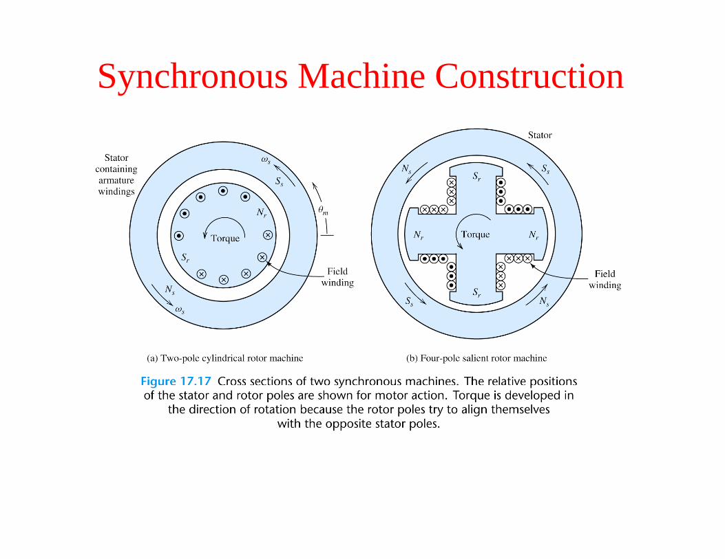
P=2Pmech •Armature windings are located on the
Vf
I f stator
•Field windings are located on the rotorlocated on the rotor
Fig. 1
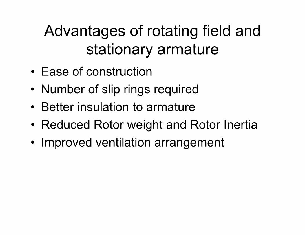
Advantages of rotating field and istationary armature
• Ease of constructionEase of construction• Number of slip rings required
B tt i l ti t t• Better insulation to armature• Reduced Rotor weight and Rotor Inertia• Improved ventilation arrangement
Various Types
Salient-pole synchronous machine
C li d i l d h hiCylindrical or round-rotor synchronous machine
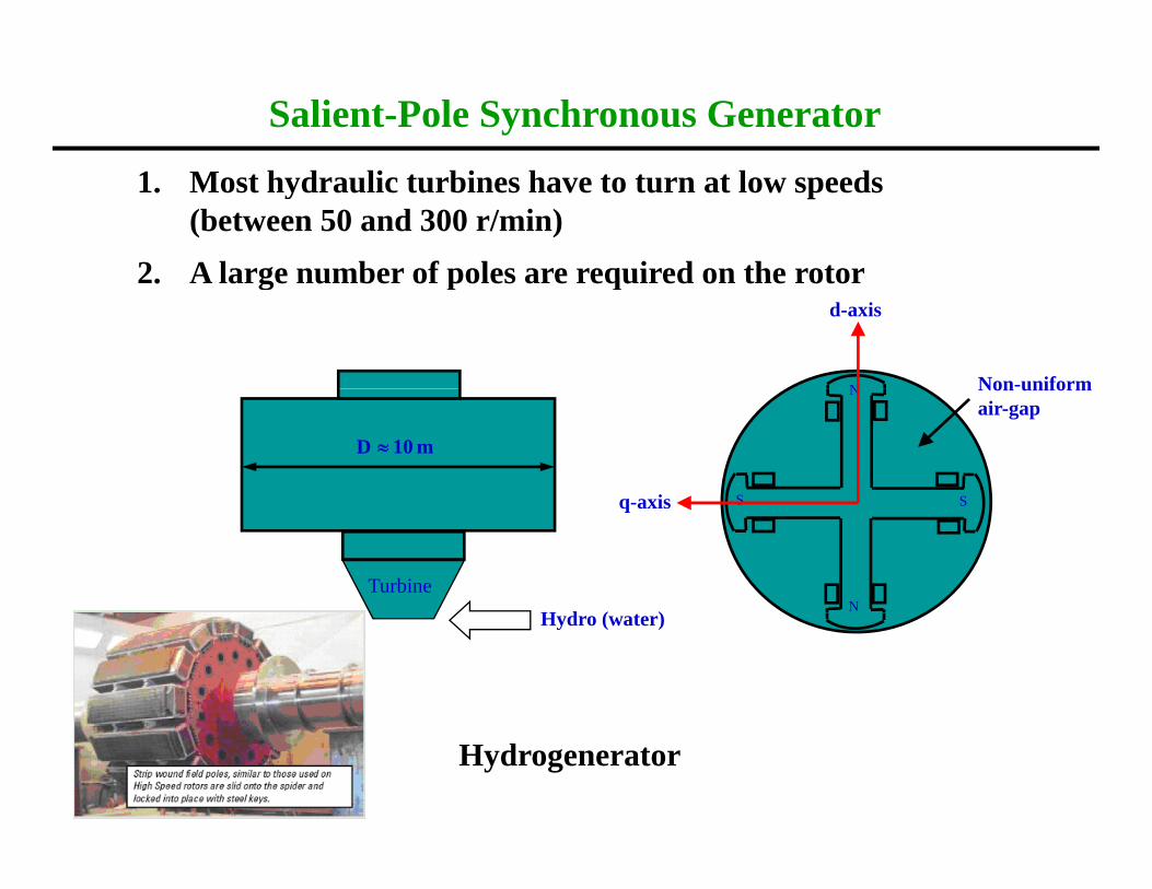
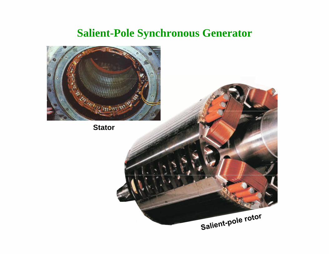
Salient-Pole Synchronous Generator
1. Most hydraulic turbines have to turn at low speeds (between 50 and 300 r/min)
2 A large number of poles are required on the rotor2. A large number of poles are required on the rotor
Non-uniformN
d-axis
D ≈ 10 m
Non uniform air-gap
N
S Sq axis
TurbineH d ( t )
S S
N
q-axis
Hydro (water)
Hydrogenerator
Synchronous Machine
•The stator is similar in construction that of a induction motor
•The rotor can be Salient or Non-Salient
•Field excitation is provided on the rotor by either permanent or electromagnets with number of poles equal to the poles of theRMF caused by statorRMF caused by stator
•Non-excited rotors are also possible as in case of reluctance motors
Synchronous Machine (2)
•The rotor gets locked to the RMF and rotates unlike induction motor at synchronous speed under all load condition
•All conventional power plants use synchronous generators forAll conventional power plants use synchronous generators for converting power to electrical form
•They operate at a better power factor and higher efficiency thanequivalent induction machines
Synchronous Machine Construction
Salient-Pole Synchronous Generator
Stator
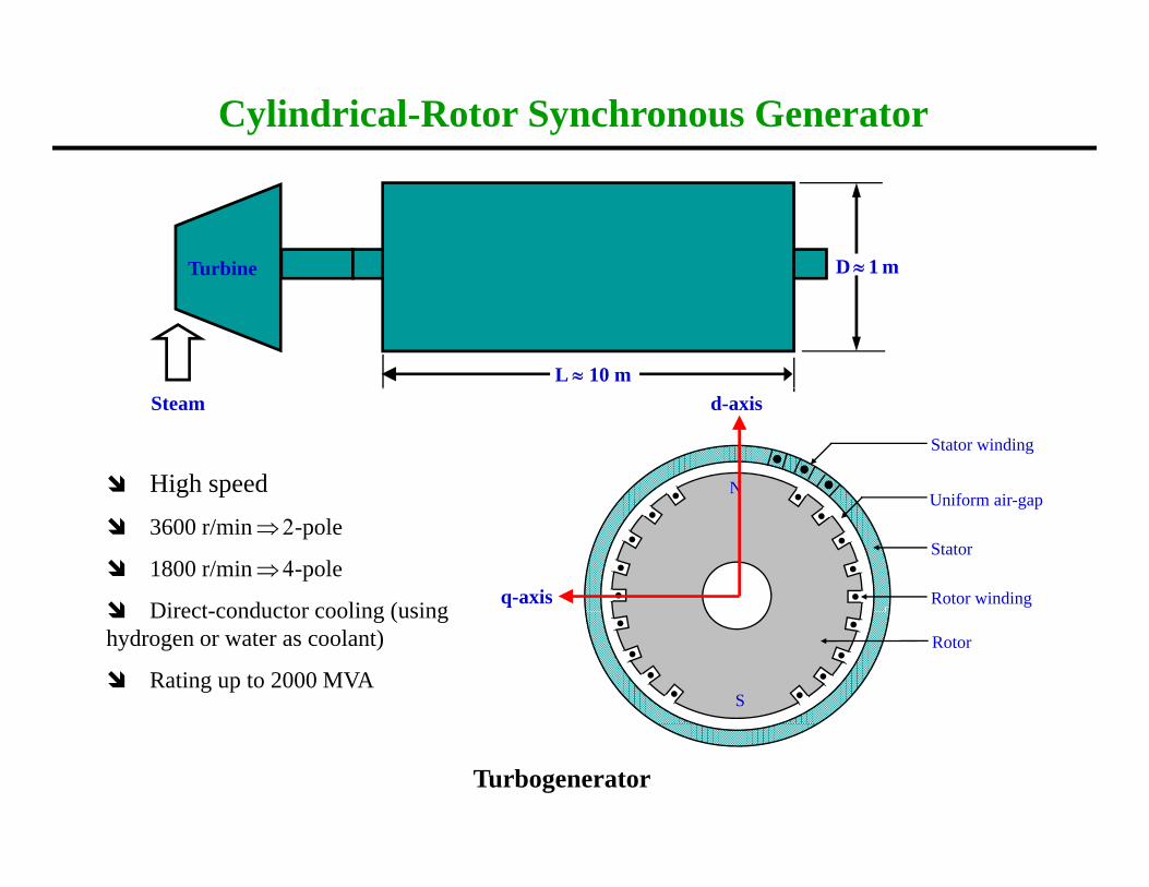
Cylindrical-Rotor Synchronous Generator
D ≈ 1 mTurbine
L ≈ 10 mSteam
Uniform air gap
Stator winding
NHigh speed
d-axis
Stator
Uniform air-gap
Rotor winding
3600 r/min ⇒ 2-pole
1800 r/min ⇒ 4-pole
Direct conductor cooling (using q-axis
Rotor
S
Direct-conductor cooling (using hydrogen or water as coolant)
Rating up to 2000 MVA
Turbogenerator

Synchronous Generator: Rotor• Salient-pole rotors– Used for low speed applications (<300rpm) which
i l b f l hi i drequire large number of poles to achieve required frequencies (e.g. hydro turbines)• Cylindrical rotors• Cylindrical rotors– Used for high-speed applications (steam/gas turbines).– Minimum number of poles is 2, so for 50Hz the p ,maximum speedis 3000rpm.– High speed of rotation produces strong centrifugal forces, which impose upper limit on the rotor diameter
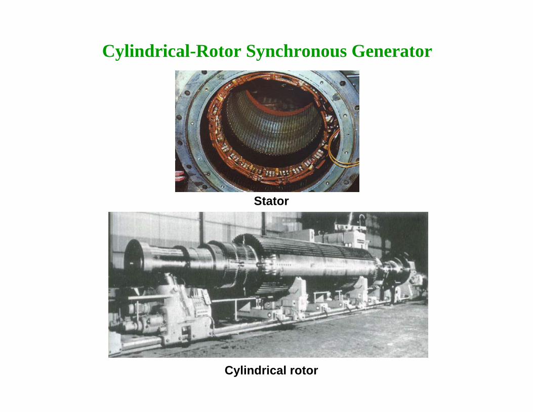
Cylindrical-Rotor Synchronous Generator
Stator
Cylindrical rotor
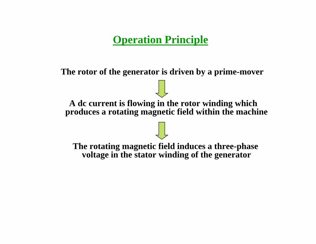
Operation Principlep p
The rotor of the generator is driven by a prime-moverg y p
A dc current is flowing in the rotor winding which g gproduces a rotating magnetic field within the machine
The rotating magnetic field induces a three-phase voltage in the stator winding of the generator
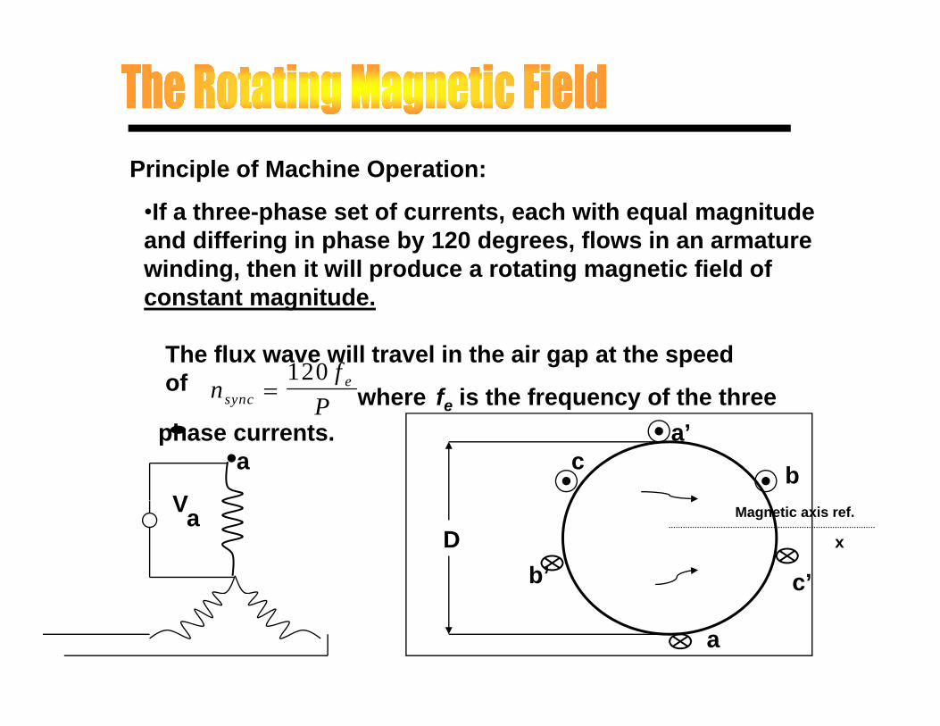
Principle of Machine Operation:
•If a three-phase set of currents, each with equal magnitude and differing in phase by 120 degrees, flows in an armature winding, then it will produce a rotating magnetic field of constant magnitude.
The flux wave will travel in the air gap at the speed of n
fPsync
e=120
where fe is the frequency of the three P e q yphase currents.
c b
a’a
V
b’ c’
DMagnetic axis ref.
xaV
a
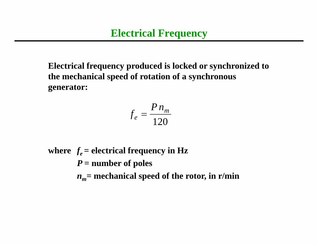
Electrical Frequency
Electrical frequency produced is locked or synchronized to the mechanical speed of rotation of a synchronousthe mechanical speed of rotation of a synchronous generator:
nP120
me
nPf =
where fe = electrical frequency in HzP = number of polesnm= mechanical speed of the rotor, in r/min
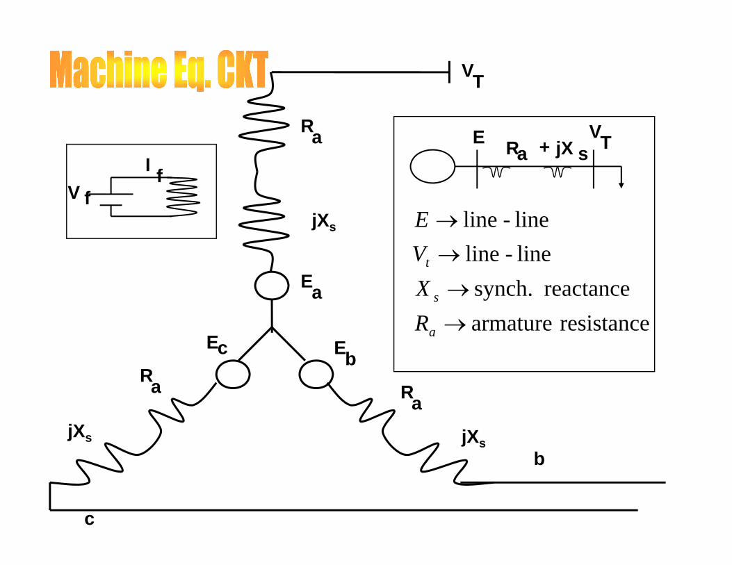
VT
I f
Ra EaR jX s+ TV
lililine - line →
VE
Vff
VjXs
i ttreactance synch.
line-line→
→
s
t
RXV
Earesistancearmature→aR
cE EbRa R
b
a
jXs jXs
Ra
b
c
Synchronous motorSynchronous motor
• Synchronous machine is provided withSynchronous machine is provided withdamper windings
• Damper winding is a short circuited• Damper winding is a short-circuitedwinding similar to the squirrel-cagewinding of induction motorwinding of induction motor
Induced Emf in a synchronous himachine
• E(average)=PZNø/60AE(average)=PZNø/60A• E(rms)/E(average)=1.11
E( ) 2 22P NT/60 (Z 2T)• E(rms)=2.22PøNT/60 (Z=2T)• N=120f/P• 2f=PN/60• E=2 22øT*2fE 2.22øT 2f• E=4.44øfT
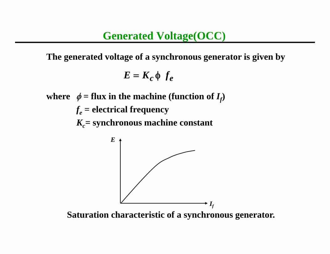
Generated Voltage(OCC)
The generated voltage of a synchronous generator is given by
ec fKE φ=
where φ = flux in the machine (function of If)f = electrical frequency
ec fφ
fe electrical frequencyKc= synchronous machine constant
E
If
Saturation characteristic of a synchronous generator.f
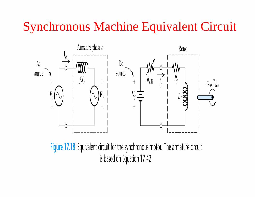
Synchronous Machine Equivalent Circuit
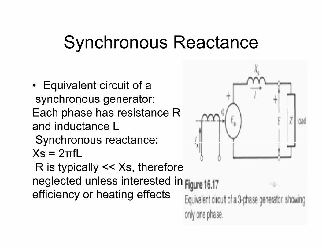
Synchronous ReactanceSynchronous Reactance
• Equivalent circuit of a synchronous generator:E h h h i REach phase has resistance Rand inductance LSynchronous reactance:Synchronous reactance:Xs = 2πfLR is typically << Xs, therefores typ ca y s, t e e o eneglected unless interested inefficiency or heating effects
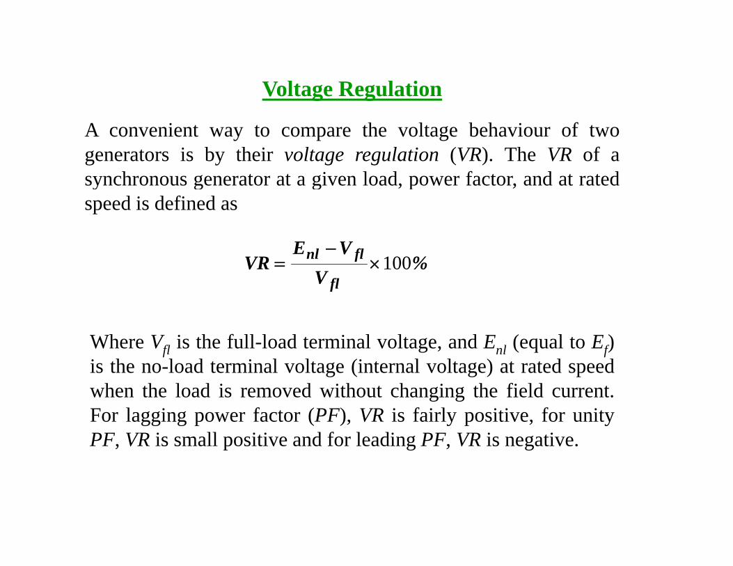
Voltage Regulation
A convenient way to compare the voltage behaviour of twogenerators is by their voltage regulation (VR). The VR of as nchrono s generator at a gi en load po er factor and at ratedsynchronous generator at a given load, power factor, and at ratedspeed is defined as
VE%
VVE
VRfl
flnl 100×−
=
Where Vfl is the full-load terminal voltage, and Enl (equal to Ef)is the no-load terminal voltage (internal voltage) at rated speedwhen the load is removed without changing the field currentwhen the load is removed without changing the field current.For lagging power factor (PF), VR is fairly positive, for unityPF, VR is small positive and for leading PF, VR is negative.
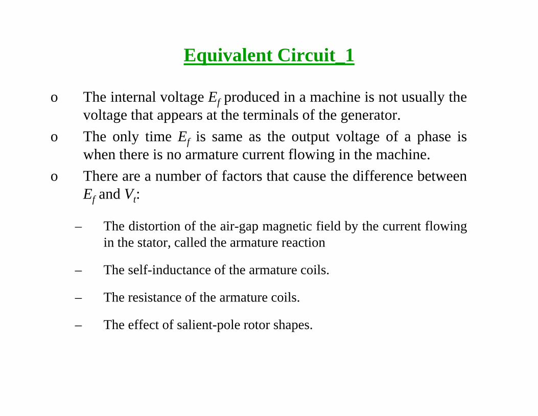
Equivalent Circuit_1
o The internal voltage Ef produced in a machine is not usually thevoltage that appears at the terminals of the generator.
o The only time Ef is same as the output voltage of a phase iswhen there is no armature current flowing in the machine.
o There are a number of factors that cause the difference betweenEf and Vt:
– The distortion of the air-gap magnetic field by the current flowingin the stator, called the armature reaction
– The self-inductance of the armature coils.
– The resistance of the armature coils.
– The effect of salient-pole rotor shapes.
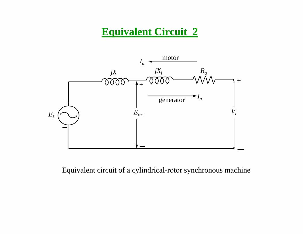
Equivalent Circuit_2
motorIa
jX jXl Ra
generator Ia
jX j l a
+ +
+ g
EfEres Vt
+
Equivalent circuit of a cylindrical-rotor synchronous machine
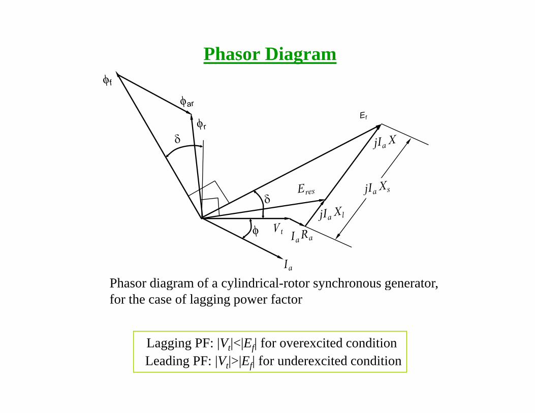
Phasor Diagram
Phasor diagram of a cylindrical-rotor synchronous generatorPhasor diagram of a cylindrical-rotor synchronous generator, for the case of lagging power factor
Lagging PF: |Vt|<|Ef| for overexcited conditionLeading PF: |Vt|>|Ef| for underexcited condition
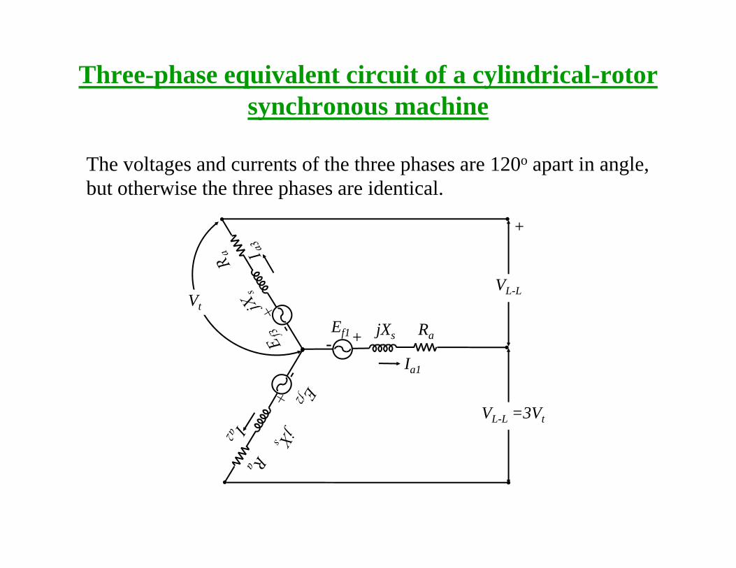
Three-phase equivalent circuit of a cylindrical-rotor synchronous machinesynchronous machine
The voltages and currents of the three phases are 120o apart in angle, but otherwise the three phases are identical.
+
VL-LVt
Ia1
Ef1 jXs Ra+
VL-L =3Vt
Determination of the parameters of the equivalent circuit from test datacircuit from test data
• The equivalent circuit of a synchronous generator that has been derived contains three quantities that must be determined in order de ved co a s ee qua es a us be de e ed o deto completely describe the behaviour of a real synchronous generator:
– The saturation characteristic: relationship between If and φ (and therefore between If and Ef)
– The synchronous reactance, Xs
– The armature resistance, Ra•
• The above three quantities could be determined by performing the f ll i th t tfollowing three tests:
– Open-circuit testShort circuit test– Short-circuit test
– DC test
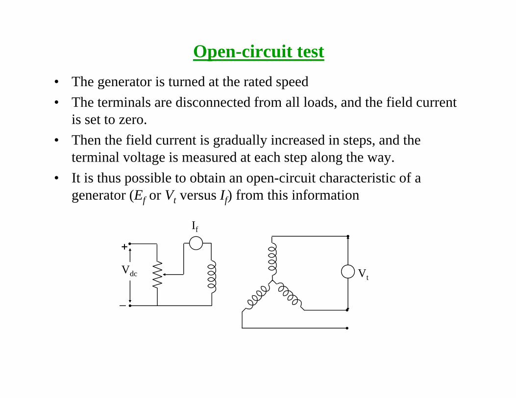
Open-circuit test• The generator is turned at the rated speed• The terminals are disconnected from all loads, and the field current
is set to zero.is set to zero.• Then the field current is gradually increased in steps, and the
terminal voltage is measured at each step along the way. It i th ibl t bt i i it h t i ti f• It is thus possible to obtain an open-circuit characteristic of a generator (Ef or Vt versus If) from this information
I
+
Vdc
If
Vdc Vt
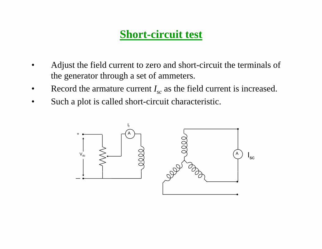
Short-circuit test
• Adjust the field current to zero and short-circuit the terminals of the generator through a set of ammetersthe generator through a set of ammeters.
• Record the armature current Isc as the field current is increased. • Such a plot is called short-circuit characteristic.
A+
If
AVdc Isc
DC Test
– The purpose of the DC test is to determine Ra. A variable DC voltage source is connected between two stator terminals. The DC source is adjusted to provide approximately rated stator current– The DC source is adjusted to provide approximately rated stator current, and the resistance between the two stator leads is determined from the voltmeter and ammeter readings
– then DCDC
DC
VRI
=
– If the stator is Y-connected, the per phase stator resistance is
2DC
aRR =
– If the stator is delta-connected, the per phase stator resistance is2a
3DCa RR
23
=
Determination of Xs
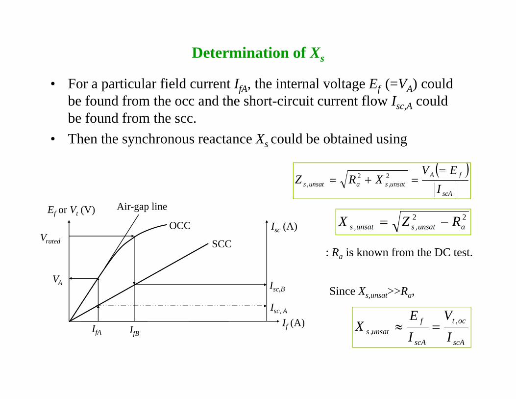
• For a particular field current IfA, the internal voltage Ef (=VA) could be found from the occ and the short-circuit current flow Isc,A could be found from the scc.
• Then the synchronous reactance Xs could be obtained using
( )fA EV =22
Ef or Vt (V) Air-gap line
OCC I (A)
( )scA
fAunsat,saunsat,s I
XRZ =+= 22
22 RZX −=OCC Isc (A)
SCCVrated
aunsat,sunsat,s RZX
: Ra is known from the DC test.
I If (A)
VA Isc,B
Isc, Aoc,tf VE
X ≈
Since Xs,unsat>>Ra,
IfAIf (A)
IfBscAscA
unsat,s IIX =≈
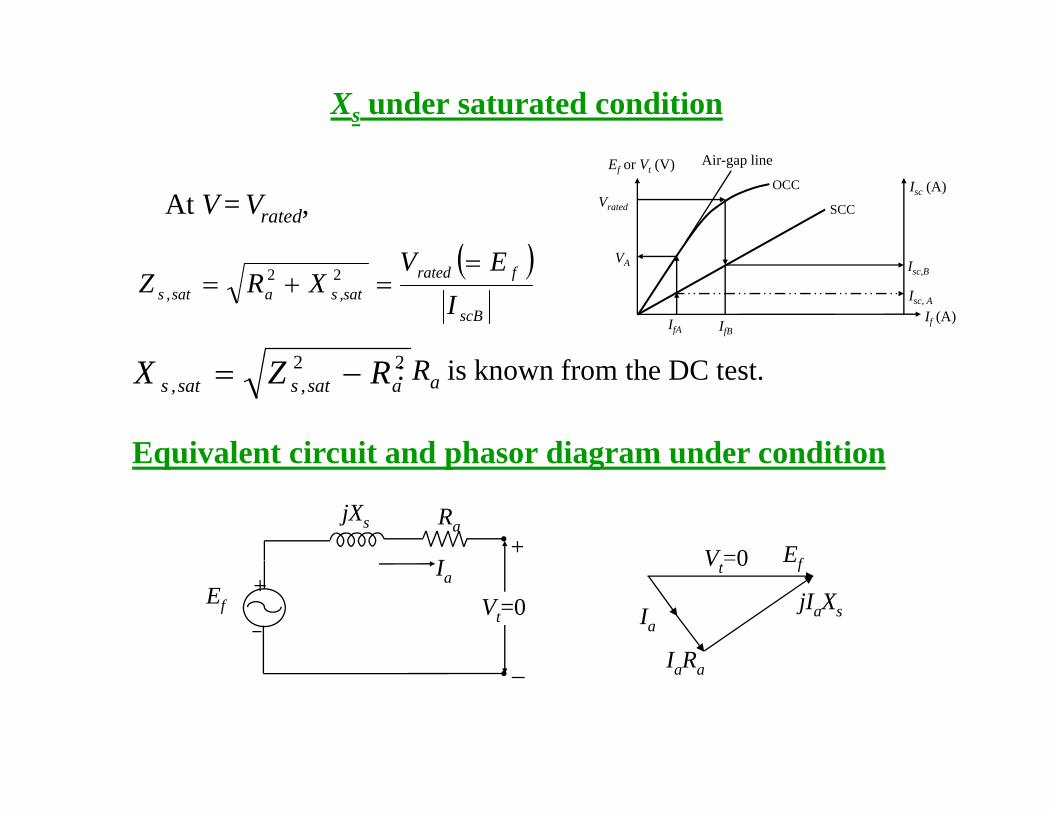
Xs under saturated condition
( )EV
At V = Vrated,Ef or Vt (V) Air-gap line
OCC Isc (A)SCCVrated
V( )scB
fratedsat,sasat,s I
EVXRZ
==+= 22
IfAIf (A)
VA Isc,B
Isc, A
IfB
22asat,ssat,s RZX −= : Ra is known from the DC test.
Equivalent circuit and phasor diagram under condition
I
jXs Ra+ EfV =0
Equivalent circuit and phasor diagram under condition
IaEf Vt=0
+EfVt 0
jIaXs
I R
Ia
IaRa
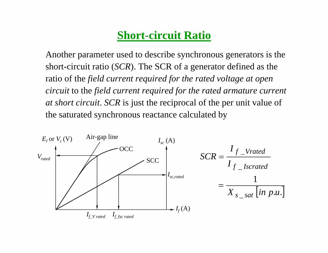
Short-circuit RatioAnother parameter used to describe synchronous generators is the short-circuit ratio (SCR). The SCR of a generator defined as the ratio of the field current required for the rated voltage at openratio of the field current required for the rated voltage at open circuit to the field current required for the rated armature current at short circuit. SCR is just the reciprocal of the per unit value of the saturated synchronous reactance calculated by
Ef or Vt (V) Air-gap line Isc (A)
I
ISCR
Iscrated_f
Vrated_f=
OCCsc ( )
SCCVrated
I
[ ].u.pinX sat_s
1=
I (A)
Isc,rated
If (A)If_V rated If_Isc rated
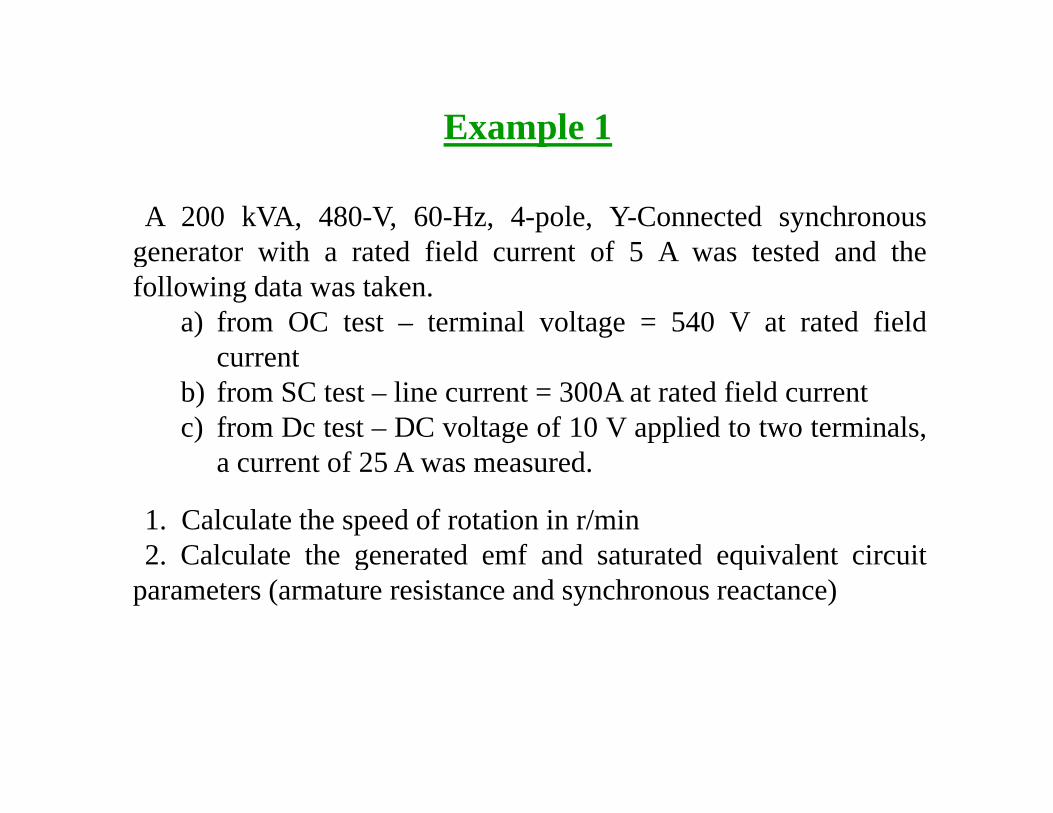
Example 1
A 200 kVA, 480-V, 60-Hz, 4-pole, Y-Connected synchronousgenerator with a rated field current of 5 A was tested and thegenerator with a rated field current of 5 A was tested and thefollowing data was taken.
a) from OC test – terminal voltage = 540 V at rated fieldcurrentcurrent
b) from SC test – line current = 300A at rated field currentc) from Dc test – DC voltage of 10 V applied to two terminals,
t f 25 A da current of 25 A was measured.
1. Calculate the speed of rotation in r/min2 Calculate the generated emf and saturated equivalent circuit2. Calculate the generated emf and saturated equivalent circuit
parameters (armature resistance and synchronous reactance)
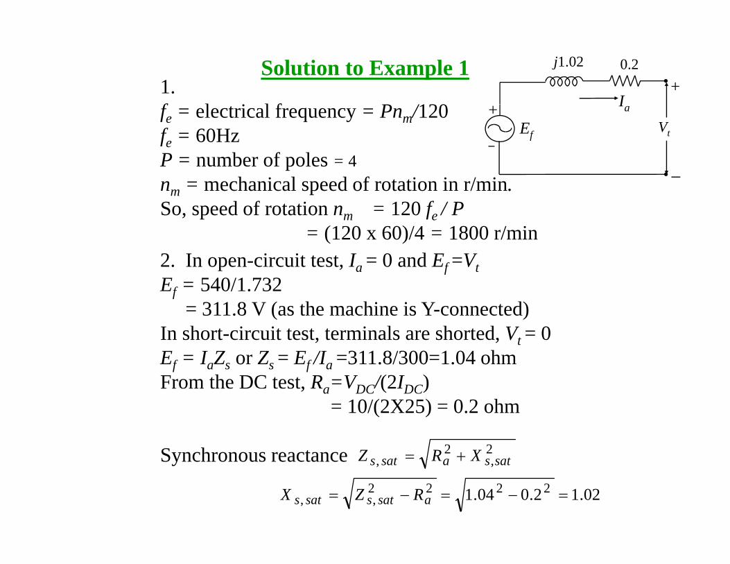
Solution to Example 11.f l i l f P /120 I
j1.02 0.2+
fe = electrical frequency = Pnm/120fe = 60HzP = number of poles = 4
Ia
Ef Vt
+
nm = mechanical speed of rotation in r/min.So, speed of rotation nm = 120 fe / P
= (120 x 60)/4 = 1800 r/min2. In open-circuit test, Ia = 0 and Ef =VtEf = 540/1.732
= 311.8 V (as the machine is Y-connected)( )In short-circuit test, terminals are shorted, Vt = 0Ef = IaZs or Zs = Ef /Ia =311.8/300=1.04 ohmFrom the DC test, Ra=VDC/(2IDC), a DC ( DC)
= 10/(2X25) = 0.2 ohm
Synchronous reactance 22satsasats XRZ +=Synchronous reactance ,, satsasats XRZ +
02.12.004.1 2222,, =−=−= asatssats RZX
Parallel operation of synchronous generators
There are several major advantages to operate generators in j g p gparallel:
• Several generators can supply a bigger load than one machine b it lfby itself.
• Having many generators increases the reliability of the power system.
• It allows one or more generators to be removed for shutdown or preventive maintenance.
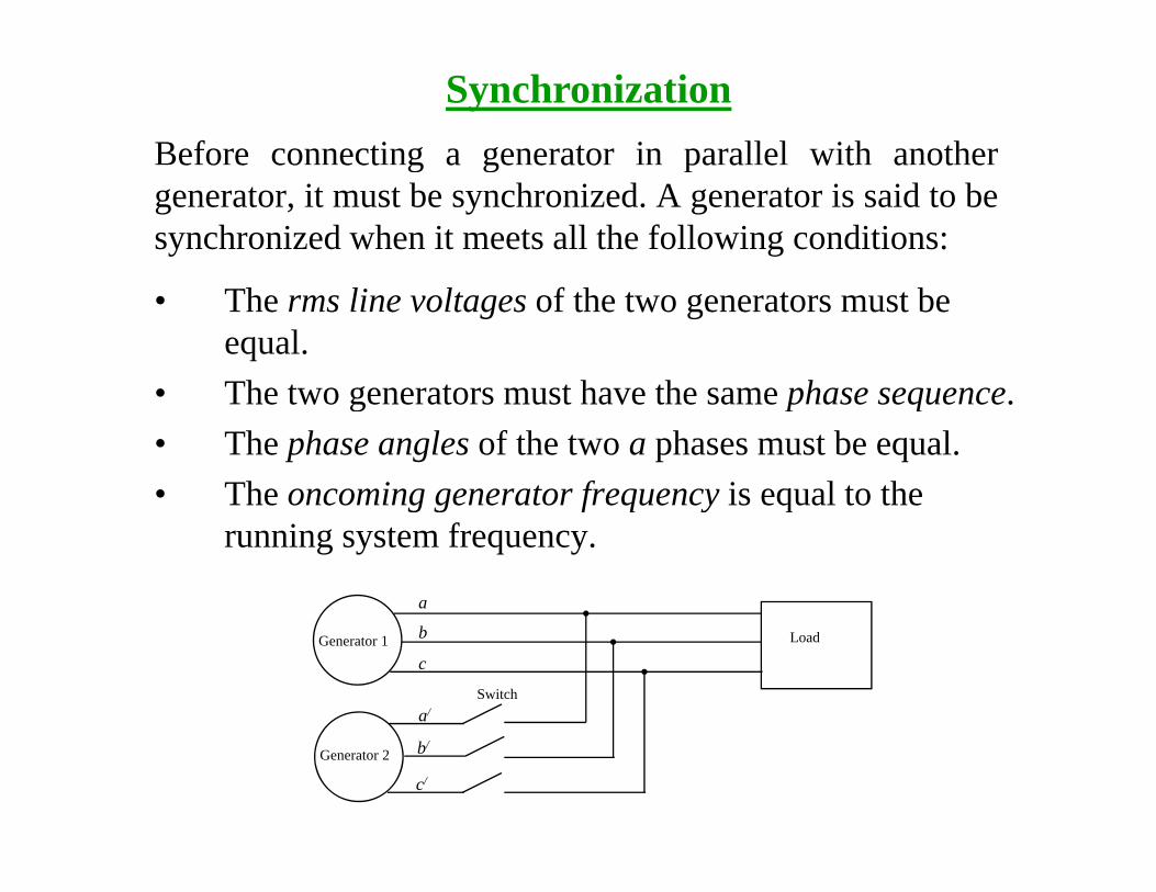
Before connecting a generator in parallel with another
Synchronizatione o e co ect g a ge e ato pa a e w t a ot e
generator, it must be synchronized. A generator is said to besynchronized when it meets all the following conditions:
• The rms line voltages of the two generators must be equal.
• The two generators must have the same phase sequence• The two generators must have the same phase sequence.• The phase angles of the two a phases must be equal.• The oncoming generator frequency is equal to theThe oncoming generator frequency is equal to the
running system frequency.
a
LoadGenerator 1
Switch
b
c
a/
Generator 2 b/
c/
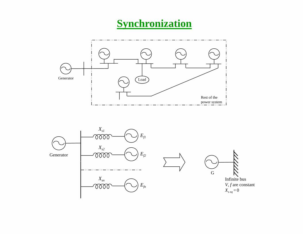
Synchronization
LoadGenerator
Rest of the power systempower system
Xs1
Generator
Ef1
Xs2Ef2
XsnEfn
Infinite busV, f are constantX = 0
G
Xs eq 0
Concept of the infinite busp
When a synchronous generator is connected to a power system,y g p y ,the power system is often so large that nothing the operator of thegenerator does will have much of an effect on the power system.An example of this situation is the connection of a singleAn example of this situation is the connection of a singlegenerator to the Canadian power grid. Our Canadian power gridis so large that no reasonable action on the part of one generatorcan cause an observable change in overall grid frequency Thiscan cause an observable change in overall grid frequency. Thisidea is idealized in the concept of an infinite bus. An infinite busis a power system so large that its voltage and frequency do notvary regardless of how much real or reactive power is drawnvary regardless of how much real or reactive power is drawnfrom or supplied to it.
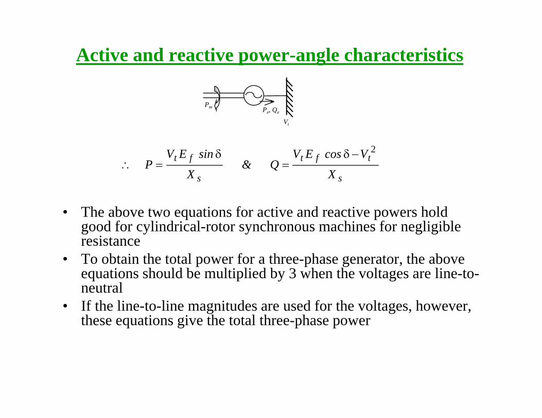
Active and reactive power-angle characteristics
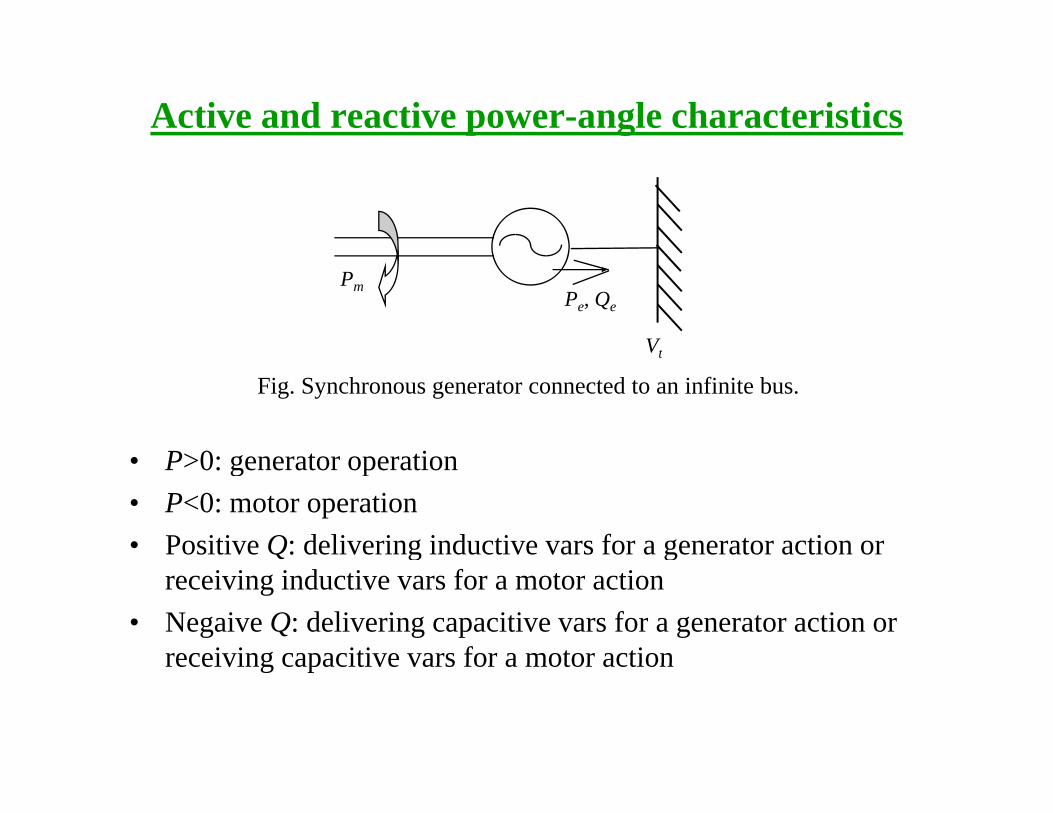
PmPe, Qe
Vt
• P>0: generator operation
t
Fig. Synchronous generator connected to an infinite bus.
• P>0: generator operation• P<0: motor operation• Positive Q: delivering inductive vars for a generator action or g g
receiving inductive vars for a motor action• Negaive Q: delivering capacitive vars for a generator action or
receiving capacitive vars for a motor actionreceiving capacitive vars for a motor action
Active and reactive power-angle characteristics
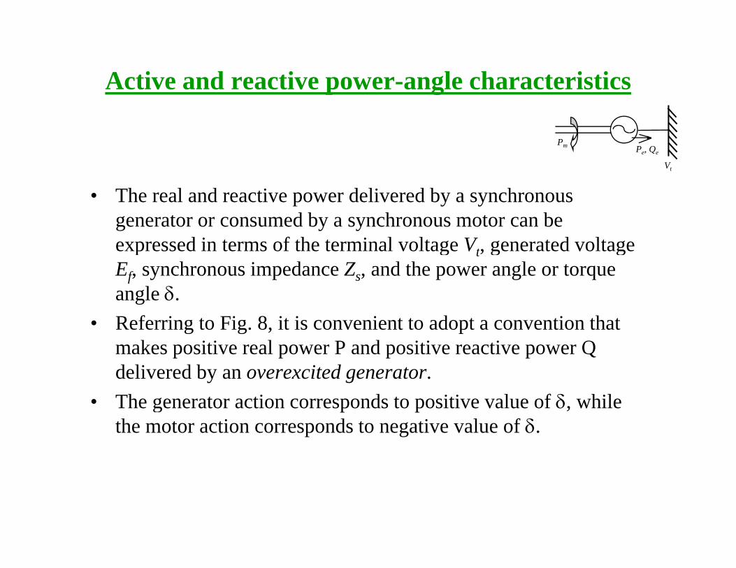
Pm Pe, Qe
Vt
• The real and reactive power delivered by a synchronous generator or consumed by a synchronous motor can be expressed in terms of the terminal voltage V generated voltageexpressed in terms of the terminal voltage Vt, generated voltage Ef, synchronous impedance Zs, and the power angle or torque angle δ. R f i t Fi 8 it i i t t d t ti th t• Referring to Fig. 8, it is convenient to adopt a convention that makes positive real power P and positive reactive power Q delivered by an overexcited generator.
• The generator action corresponds to positive value of δ, while the motor action corresponds to negative value of δ.
Active and reactive power-angle characteristics
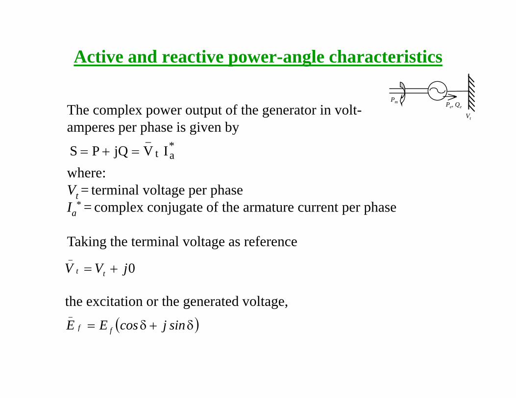
The complex power output of the generator in volt-h i i b
Pm Pe, Qe
Vt
amperes per phase is given by*at
_IVjQPS =+=
where:where:Vt = terminal voltage per phaseIa
* = complex conjugate of the armature current per phase
Taking the terminal voltage as reference
0jVV tt
_
+= jt
the excitation or the generated voltage,
( )δ+δ= sinjcosEE_
( )δ+δ= sinjcosEE ff
Active and reactive power-angle characteristics
Pm Pe, Qe
V
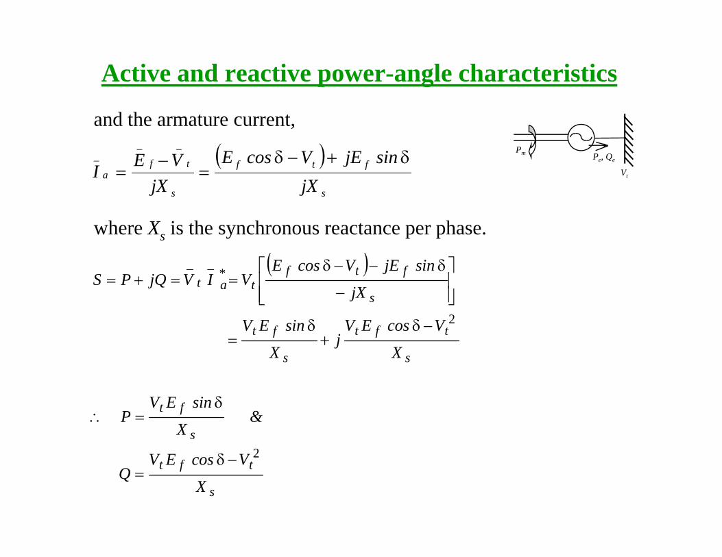
and the armature current,
( ) ftft
_
f
__ sinjEVcosEVEI
δ+−δ=
−= Vt
ss
ajXjX
I ==
where Xs is the synchronous reactance per phase.
( )s
ftft
*a
_t
_
jX
sinjEVcosEVIVjQPS
⎥⎥⎦
⎤
⎢⎢⎣
⎡
−
δ−−δ==+=
s
tft
s
ft
X
VcosEVj
X
sinEV 2−δ+
δ=
s
ft
VEV
&X
sinEVP
2δ
δ=∴
s
tft
X
VcosEVQ
2−δ=
Active and reactive power-angle characteristics
Pm Pe, Qe
Vt
s
tft
s
ft
X
VcosEVQ&
X
sinEVP
2−δ=
δ=∴
• The above two equations for active and reactive powers hold good for cylindrical-rotor synchronous machines for negligible
iresistance• To obtain the total power for a three-phase generator, the above
equations should be multiplied by 3 when the voltages are line-to-neutralneutral
• If the line-to-line magnitudes are used for the voltages, however, these equations give the total three-phase power
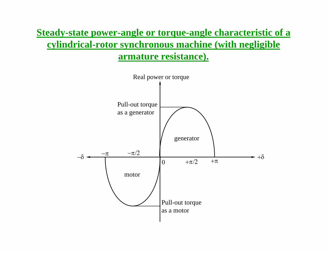
Steady-state power-angle or torque-angle characteristic of a cylindrical-rotor synchronous machine (with negligiblecylindrical rotor synchronous machine (with negligible
armature resistance).
Real power or torqueReal power or torque
Pull-out torque t
generator
as a generator
+δ
motor
+π+π/2−π/2
0−π−δ
motor
Pull-out torque as a motor
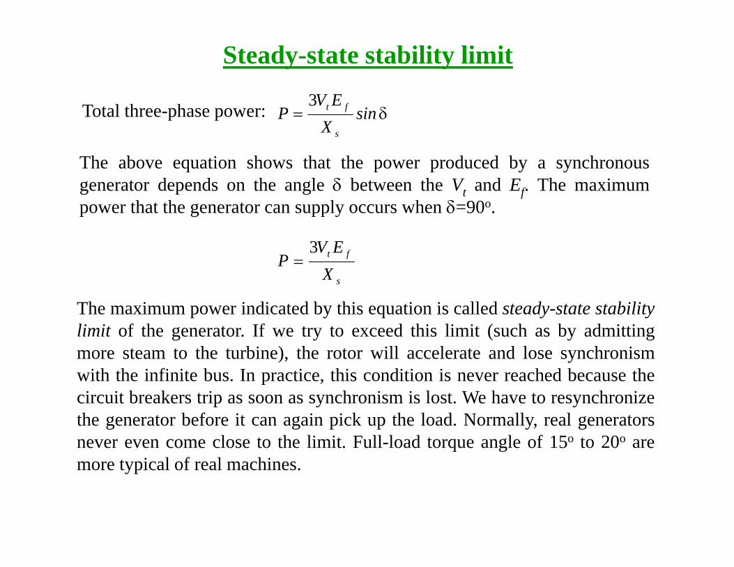
Steady-state stability limit
T l h h EV ft3Total three-phase power: δ= sinX
EVP
s
ft3
The above equation shows that the power produced by a synchronousgenerator depends on the angle δ between the Vt and Ef. The maximumpower that the generator can supply occurs when δ=90o.
EV3
s
ft
XEV
P3
=
The maximum power indicated by this equation is called steady-state stabilitylimit of the generator. If we try to exceed this limit (such as by admittingmore steam to the turbine), the rotor will accelerate and lose synchronismwith the infinite bus. In practice, this condition is never reached because thei i b k i h i i l h h icircuit breakers trip as soon as synchronism is lost. We have to resynchronize
the generator before it can again pick up the load. Normally, real generatorsnever even come close to the limit. Full-load torque angle of 15o to 20o aremore typical of real machinesmore typical of real machines.
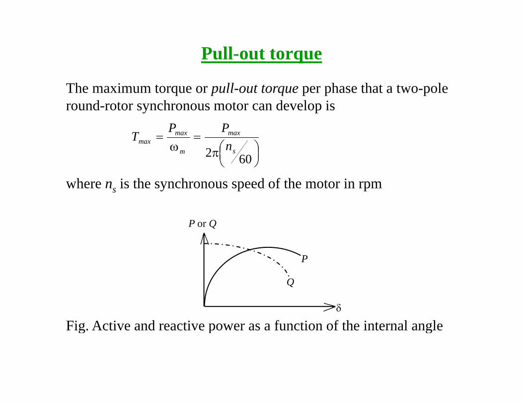
Pull-out torque
The maximum torque or pull-out torque per phase that a two-pole round-rotor synchronous motor can develop is
PP
⎟⎠⎞⎜
⎝⎛π
=ω
=
602 s
max
m
maxmax n
PPT
where ns is the synchronous speed of the motor in rpm
P or Q
P
Q
δ
Q
Fig Active and reactive power as a function of the internal angleFig. Active and reactive power as a function of the internal angle
Synchronous Motors
A h i h h i l hi
P, Q
Vt
Motor
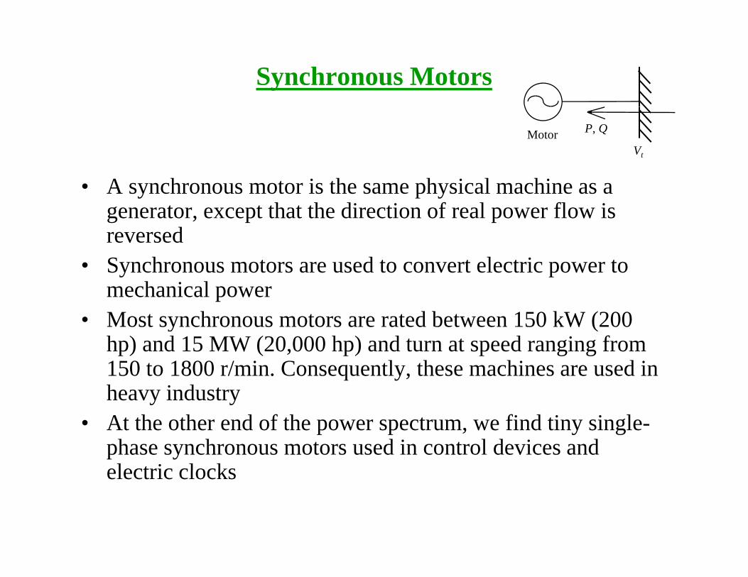
• A synchronous motor is the same physical machine as a generator, except that the direction of real power flow is reversed
• Synchronous motors are used to convert electric power to mechanical power
• Most synchronous motors are rated between 150 kW (200Most synchronous motors are rated between 150 kW (200 hp) and 15 MW (20,000 hp) and turn at speed ranging from 150 to 1800 r/min. Consequently, these machines are used in heavy industryheavy industry
• At the other end of the power spectrum, we find tiny single-phase synchronous motors used in control devices and electric clockselectric clocks
Operation Principle
• The field current of a synchronous motor produces a steady-state magnetic field BR
A th h t f lt i li d t th t t i di f• A three-phase set of voltages is applied to the stator windings of the motor, which produces a three-phase current flow in the windings. This three-phase set of currents in the armature winding produces a uniform rotating magnetic field of Bs
• Therefore, there are two magnetic fields present in the machine, and the rotor field will tend to line up with the stator field justand the rotor field will tend to line up with the stator field, just as two bar magnets will tend to line up if placed near each other.
• Since the stator magnetic field is rotating, the rotor magnetic g g gfield (and the rotor itself) will try to catch up
• The larger the angle between the two magnetic fields (up to certain maximum) the greater the torque on the rotor of thecertain maximum), the greater the torque on the rotor of the machine
Vector Diagramg
• The equivalent circuit of a synchronous motor is exactly same as h i l i i f h h hthe equivalent circuit of a synchronous generator, except that the
reference direction of Ia is reversed. • The basic difference between motor and generator operation in
synchronous machines can be seen either in the magnetic field diagram or in the phasor diagram.
• In a generator Ef lies ahead of Vt and BR lies ahead of B t In aIn a generator, Ef lies ahead of Vt, and BR lies ahead of Bnet. In a motor, Ef lies behind Vt, and BR lies behind Bnet.
• In a motor the induced torque is in the direction of motion, and in a generator the induced torque is a countertorque opposing thegenerator the induced torque is a countertorque opposing the direction of motion
Vector Diagram
δ
Ia
VtjIa Xs
Bs
Bnetω
Ef
δnet
BR
ωsync
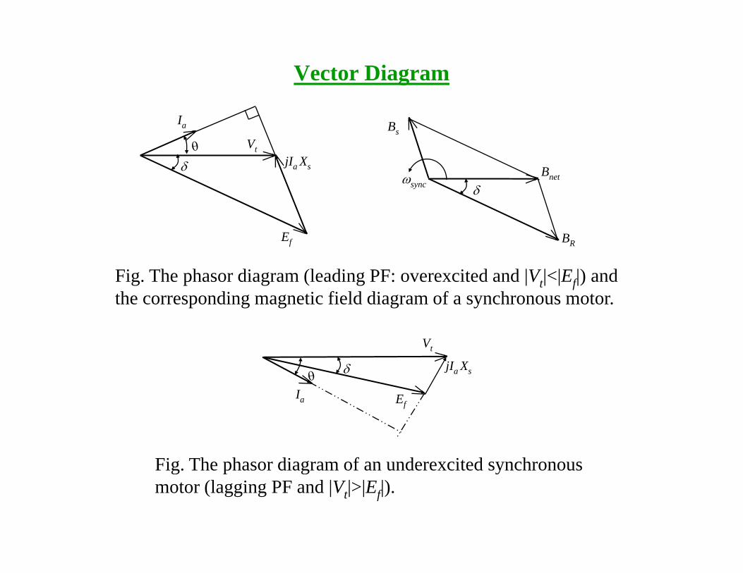
Fig. The phasor diagram (leading PF: overexcited and |Vt|<|Ef|) and the corresponding magnetic field diagram of a synchronous motor.
δ
I
Vt
E
jIa Xs
Ia Ef
Fig The phasor diagram of an underexcited synchronousFig. The phasor diagram of an underexcited synchronous motor (lagging PF and |Vt|>|Ef|).
Application of Synchronous Motors
Synchronous motors are usually used in large sizes because in small sizes they are costlier as compared with induction machines. The principal advantages of using synchronous machine are as follows:advantages of using synchronous machine are as follows:
– Power factor of synchronous machine can be controlled very easily by controlling the field current.y g
– It has very high operating efficiency and constant speed.– For operating speed less than about 500 rpm and for high-power
requirements (above 600KW) synchronous motor is cheaper thanrequirements (above 600KW) synchronous motor is cheaper than induction motor.
In view of these advantages, synchronous motors are preferred for driving the loads requiring high power at low speed; e.g; reciprocating pumps and compressor, crushers, rolling mills, pulp grinders etc.


![Dronacharya College of Engineeringggn.dronacharya.info/Downloads/Newsletter/Newsletter_Oct_13.pdf · [2] E-mail : info@dronacharya.info visit us at Events : CSE department has a blooming](https://img.dokumen.tips/doc/110x75/5fb001de1abff43c9233d1f5/dronacharya-college-of-2-e-mail-infodronacharyainfo-visit-us-at-events-cse.jpg)

