Embed Size (px)
Citation preview

©2010 Harsco Industrial, Patterson-Kelley Printed : 4/30/2012
MACH® GAS FIRED BOILER
C1500H/C2000H/C2500/C3000/C4000
Natural Gas/Propane/Dual Fuel
Model #:_______ Serial #______________________ Start-Up Date: _______________________ Harsco Industrial, Patterson-Kelley 100 Burson Street East Stroudsburg, PA 18301 Telephone: 570.476.7261 Toll Free: 877.728.5351 Facsimile: 570.476.7247 www.harscopk.com
MACH® C1500H – C4000 Rev. 1.02 (04/30/2012)
C.S.A Design-Certified Complies with ANSI Z21.13/CSA 4.9 Gas-Fired Low Pressure Steam and Hot Water Boilers ASME Code, Section IV Certified by Harsco Industrial, Patterson-Kelley C.S.A Design-Certified Complies with ANSI Z21.13/CSA 4.9 Gas-Fired Low Pressure Steam and Hot Water Boilers

MACH® Gas Fired Boiler
2

MACH® Gas Fired Boiler
3
1 ..... INTRODUCTION ................................................................................................................................................ 7
2 ..... SAFETY .............................................................................................................................................................. 7
2.1 General ............................................................................................................................................. 7 2.2 Training ............................................................................................................................................. 8 2.3 Safety Features ................................................................................................................................ 8 2.4 Safety Labels .................................................................................................................................... 8 2.5 Safety Precautions ........................................................................................................................... 9
3 ..... INSTALLATION ................................................................................................................................................ 11
3.1 Receiving and Storage ................................................................................................................... 11 3.2 Compliance with Codes .................................................................................................................. 12 3.3 Setup .............................................................................................................................................. 12 3.4 Electrical Connections .................................................................................................................... 13 3.5 Inlet Air and Exhaust Venting ......................................................................................................... 16 3.6 Gas Piping ...................................................................................................................................... 29 3.7 Boiler Water Piping ......................................................................................................................... 31 3.8 Pre-Start Check List ....................................................................................................................... 37 3.9 Safety Checks ................................................................................................................................. 37 3.10 Initial Adjustments .......................................................................................................................... 39 3.11 Fuel/Air Adjustment ........................................................................................................................ 42
4 ..... OPERATION ..................................................................................................................................................... 44
4.1 General ........................................................................................................................................... 44 4.2 Normal Lighting and Shut-Down Procedures ................................................................................. 45 4.3 Emergency Shut-Off ....................................................................................................................... 46 4.4 Typical Boiler Operating Conditions ............................................................................................... 46
5 ..... MAINTENANCE ............................................................................................................................................... 47
5.1 Maintenance and Inspection Schedule .......................................................................................... 47 5.2 Cleaning the Burner ........................................................................................................................ 49 5.3 Removing the Heat Exchanger ....................................................................................................... 50 5.4 After All Repairs or Maintenance .................................................................................................... 50 5.5 Sequence of Operation ................................................................................................................... 50 5.6 Troubleshooting .............................................................................................................................. 51 5.7 Manual reset error codes-A##A (OR LOCKING ERROR CODES) ............................................... 53 5.8 Auto-reset error codes-E## (or blocking error codes) .................................................................... 54
6 ..... PARTS/TECHNICAL SUPPORT ..................................................................................................................... 55
6.1 Wiring Diagrams ............................................................................................................................. 56 6.2 Boiler Parts List ............................................................................................................................... 69
7 ..... MACH® BOILER LIMITED WARRANTY ......................................................................................................... 80
8 ..... APPENDIX ........................................................................................................................................................ 81
8.1 Appendix 1 – MACH® Boiler Fire Test Report ................................................................................ 81 8.2 Appendix 2 – MACH® Boiler Maintenance Log .............................................................................. 82 8.3 Appendix 3 – MACH® Boiler Altitude Derate schedule ................................................................... 83

MACH® Gas Fired Boiler
4
Reorder No. 6020-V2WHPK
Improper use mayresult in fire or injury.Read instructions/safetymanual before installing, operating or servicing boiler.
c
! WARNING
1998 HCS, Inc. 800-748-0241
If the information in these instructions are not followed exactly, a fire or explosion may result causing property damage, personal injury or death.
Do not store or use gasoline or other flammable vapors or liquids in the vicinity of this or any other appliance.
What to do if you smell gas:
Do not try to light any appliance. Do not touch any electrical switch; do not use any phone in your building. Immediately call your gas supplier from a neighbor's phone. Follow the gas supplier's instructions. If you cannot reach your gas supplier, call the fire department.
Installation and service must be performed by a qualified installer, service agency, or the gas supplier.
AVERTISSEMENT! Assurez-vous de bien suivre les instructions données dans cette notice pour réduire au minimum le risqué d'incendie ou d'explosion ou pour éviter tout dommage matériel, toute blessure ou la mort. — Ne pas entreposer ni utiliser d'essence ni d'autres vapeurs ou liquids inflammables dans le voisinage de cet appareil ou de tout autre appareil. — QUE FAIRE SI VOUS SENTEZ UNE ODEUR DE GAZ: • Ne pas tenter d’allumer d’appareils. • Ne touchez à aucun interrupteur. Ne pas vous servir des téléphones dans le bâtiment où vous vous trouvez. • Appelez immédiatement votre fournisseur de gaz depuis un voisin. Suivez les instructions du fournisseur. • Si vous ne pouvez rejoindre le fournisseur de gaz, appelez le service des incendies. — L’installation et l’entretien doivent être assurés par un installateur ou un service d’entretien qualifié ou par le fournisseur de gaz.
It is essential to read, understand, and follow the recommendations of this manual before installing, operating, or servicing this equipment.

MACH® Gas Fired Boiler
5
Installation and service must be performed by a qualified and knowledgeable individual who has been trained on the Harsco Industrial, Patterson-Kelley MACH® boiler. The same features which permit this boiler to achieve high-efficiency performance make it unlike most other boilers of this general size, so it is important to understand how this boiler operates.

MACH® Gas Fired Boiler
6

MACH® Gas Fired Boiler
7
1 INTRODUCTION This manual describes the installation and operation of MACH® boilers with inputs from 1.5 million through 4 million BTUH. Natural gas, propane, and dual fuel (natural and propane) units are described. It also includes 208/3/60, 240/3/60, or 480/3/60 voltages for the 3 and 4 million BTUH input boilers. This manual describes the natural gas design. Information for operation with other fuels is included in the various sections of this manual as applicable. If you have any questions on the information contained within, or do not fully and completely understand the content, please contact Harsco Industrial, Patterson-Kelley Technical Service at 570.476.7261 or toll free at 877.728.5351. The MACH® C1500H/C2000H/C2500/C3000/C4000 gas fired boilers are fully modulating using variable speed combustion blowers, sophisticated microprocessor controls, modulating gas safety shut off / control valves and a unique aluminum alloy heat exchanger capable of operating in a fully condensing mode to provide maximum efficiency in a minimum amount of space. The high quality materials and thoroughly tested design of the boiler should provide years of trouble free service if the instructions in this manual are followed carefully.
This manual covers the installation of MACH® C1500H/C2000H/C2500/C3000/C4000 natural gas, propane, and dual fuel (natural gas and propane) boilers. The model number may be followed by a prefix or suffix letter in some cases to indicate special features or different options.
While details may differ slightly, basic operation is the same for all models. Check the rating plate for correct fuel usage and gas pressures.
The boiler is only a part of the complete heating system. This boiler may be fully operational and yet because of poor circulation, control, or other operating characteristics not deliver heat to the desired location. Additional equipment such as temperature sensors, pumps, flow switches, balancing valves, and check valves will be required for satisfactory operation of any system. Harsco Industrial, Patterson-Kelley cannot be responsible for the design or operation of such systems and a qualified engineer or contractor must be consulted.
2 SAFETY 2.1 GENERAL
The MACH® C1500H/C2000H/C2500/C3000/C4000 gas fired boilers must be: Installed, operated, and serviced in accordance with instructions contained in this manual and other supplemental
manuals.
Installed by qualified personnel in accordance with designs prepared by qualified facility engineers including: structural, mechanical, electrical, and other applicable disciplines.
Operated and serviced in accordance with a comprehensive safety program determined and established by the customer. Do not attempt to operate or service until such a program has been established.
Operated and serviced by experienced, qualified, and properly trained personnel in accordance with all applicable codes, laws, and regulations.
NOTICE! Each safety device must be maintained and checked per the recommended schedule. Refer to Section 5.1 of this manual.

MACH® Gas Fired Boiler
8
2.2 TRAINING
Proper training is the best protection against accidents.
It is essential to read, understand, and follow the recommendations of this manual before installing, operating, or servicing this equipment. Failure to do so could result in fire or explosion and serious injury, death, and/or property damage.
Operating and service personnel must be thoroughly familiar with the basic construction of the MACH® C1500H/C2000H/C2500/C3000/C4000 boilers, the use and locations of the controls, the operation of the boilers, adjustment of their various mechanisms, and all applicable safety precautions. If any of the provisions of this manual are not fully and completely understood, contact Harsco Industrial, Patterson-Kelley Technical Service at 570.476.7261 or toll free at 877.728.5351.
2.3 SAFETY FEATURES
It is the responsibility of the customer to maintain the safety features, such as but not limited to: guards, safety labels, safety controls, interlocks, lockout devices, in place and operable.
2.4 SAFETY LABELS
The following words are used in this manual to de-note the degree of seriousness of the individual hazards.
Indicates an imminently hazardous situation which, if not avoided, will result in death or serious injury. This signal word is to be limited to the most extreme situations.
Indicates a potentially hazardous situation which, if not avoided, could result in death or serious injury.
Indicates a potentially hazardous situation which, if not avoided, may result in minor or moderate injury. It may also be used to alert against unsafe practices. NOTICE/NOTE - NOTICE is the preferred signal word to address practices not related to personal injury. The safety alert symbol is not used with this signal word.

MACH® Gas Fired Boiler
9
The safety labels shown above are affixed to your boiler. Although the labels are of high quality, they may become dislodged or unreadable over time. Contact Harsco Industrial, Patterson-Kelley at 570.476.7261 or toll-free at 877.728.5351 for replacement labels.
2.5 SAFETY PRECAUTIONS
Provide a suitable location for the boiler, away from normal personnel traffic, with adequate working space, adequate clearances, proper ventilation and lighting, with a structure sufficiently strong and rigid to support the weight of the boiler, all piping, and accessories.
2.5.1 Electrical Hazards
Shock hazard! Properly lockout/tag out the electrical service and all other energy sources before working on or near the boiler.
Shock hazard! Do not spray water directly on this boiler or on any electrical components.
Electrical hazard! Do not alter wiring connections.
2.5.2 Burn, Fire, and Explosion Hazards
Burn, fire, and explosion hazards! Installation must be in strict conformance to all applicable codes and standards including NFPA 54, ANSI Z223.1 and CAN/CSA B.149. Install all required vent lines for gas devices. Refer to Section 3.6.
Hazard from incorrect fuels! Possible fire, explosion, overheating, and damage. Do not use any fuels except the design fuels for the unit.
Over fire hazards! High pressure in gas supply could result in over firing of this or other devices supplied from the same source.
Fire and explosion hazards! Close the main gas shutoff before servicing boiler.
Fire and explosion hazards! Do not store or use gasoline or other flammable vapors or liquids in the vicinity of this or any other gas fired appliance.
Burn hazard! Possible hot surfaces. Do not touch gas vent during firing operation. Use only factory recommended vent components.
Burn hazard! Pipes, vents, and boiler components could be hot. Do not touch piping or stack surfaces during operation or immediately after shutdown of the boiler.
Burn hazard! Hot fluids. Use caution when servicing or draining boiler. Hot Surface
Reorder No. 6020-V2WHPK
Improper use mayresult in fire or injury.Read instructions/safetymanual before installing, operating or servicing boiler.
c
! WARNING
1998 HCS, Inc. 800-748-0241
General Warning
Reorder No. 6020-V2WHPK
Improper use mayresult in fire or injury.Read instructions/safetymanual before installing, operating or servicing boiler.
c
! WARNING
1998 HCS, Inc. 800-748-0241

MACH® Gas Fired Boiler
10
Fire and explosion hazards! Use caution when servicing burner. Propane (LPG) is heavier than air and may linger in the combustion chamber, vent lines, or elsewhere.
Gas leak hazard! Make sure the burner is installed correctly and blower/transition is securely fastened following any maintenance performed on them. These connections may leak gas if assembled incorrectly.
Gas leak hazard! All threaded gas connections must be made using a pipe compound that is resistant to liquefied petroleum gas. Do not use Teflon tape on threaded gas piping.
Gas leak hazard! Check entire gas train for leaks after installation. If there is a smell of gas, shut down the boiler and obtain immediate assistance from trained service personnel and/or your local fire department.
Over fire hazard! Possible fire and explosion from excess gas pressure. Make sure that gas inlet pressure does not exceed 14 inches W.C.
Over fire hazard! Possible fire and explosion. Possible malfunction of regulators and/or gas safety shut off / control valves. Maintain all gas train components in good condition. Do not alter wiring connections. Annual inspection by factory-trained personnel for proper set-up and operation is recommended.
Over fire and under fire hazards! Possible fire, explosion, overheating, and component failure. Do not attempt to adjust firing rate of the boiler. The firing rate must be adjusted only by factory trained personnel.
Gas may lose its odor. Proper gas sensing equipment and procedures should be used for leak checks.
2.5.3 Crush Hazards
Lifting hazards! Use properly rated lifting equipment to lift and position the boiler. The load is unbalanced. Test balance before lifting 3 ft. above the floor. Do not allow personnel beneath the lifted load. Refer to approximate weights in the table.
Bump hazard from overhead ductwork and piping. Install components with adequate vertical clearance.
2.5.4 Chemical Hazards
• Chemical hazards from cleaning products. Use caution when cleaning the system. The use of professional assistance is recommended. Use safe procedures for the disposal of all cleaning solutions.
• Combustion Condensate – an acidic pH of approximately 3.0 to 5.0 can be expected. Use PVC, CPVC, or other corrosion resistant piping for drainage. Collection and disposal must be in accordance with all applicable regulations. A condensate neutralization kit is available. Please contact your local Harsco Industrial, Patterson-Kelley representative.
Boiler Size Weight in Pounds
C1500H 1,200 lbs
C2000H 1,400 lbs
C2500 1,550 lbs
C3000 1,600 lbs
C4000 1,900 lbs
General Warning
General Warning
MACH® Gas Fired Boiler
11
2.5.5 Pressure Hazards
Pressure hazard! Hot fluids. Install isolation valves on boiler water inlet and outlet. Make sure isolation valves are closed before servicing boiler.
Pressure hazard! Hot fluids. Annually test safety relief valve for proper operation. Do not operate boiler with faulty relief valve.
2.5.6 Slip, Fall Hazards
Tripping hazard! Do not install piping on floor surfaces. Maintain clear path around boiler.
Slip and fall hazard! Use drip pan to catch water while draining the boiler. Maintain dry floor surfaces.
Slip and fall hazard! Do not locate intake or exhaust terminations directly above a walkway; dripping of condensation can cause icing of the walking surface. (see section 3.5)
Fall hazard! Do not stand on boiler.
3 INSTALLATION
Installation and service must be performed by a qualified installer, service agency, or gas supplier.
3.1 RECEIVING AND STORAGE
3.1.1 Initial Inspection
Upon receiving the boiler, inspect it for signs of shipping damage. Since some damage may be hidden, unpack the boiler, open the front, and side doors and inspect the boiler. Verify that the total number of pieces shown on the packing slip agrees with those actually received.
NOTICE! Note any damage, suspected potential damage, or shortage of materials on the freight bill and immediately notify the carrier. File all claims for shortage or damage with the carrier. Claims for hidden damages must be filed with your carrier within 7 days. The boiler carton is equipped with a “Tip (N) Tell”. If "Tip (N) Tell” arrow point is blue, that indicates that the package has been on its side or tipped over in transit.
3.1.2 Storage Prior to Installation
If the boiler is not installed immediately, it must be stored in a location adequately protected from the weather, preferably indoors. If this is not possible, then it should remain in the shipping container and be covered by a tarpaulin or other waterproof covering.
NOTICE! Controls and other equipment that are damaged or fail due to weather exposure are not covered by warranty.
General Warning
General Warning

MACH® Gas Fired Boiler
12
3.2 COMPLIANCE WITH CODES
MACH® boilers with standard components and with many options complies with American National Standard/CSA Standard ANSI Z21.13/CSA 4.9, latest edition, Gas Fired Low Pressure Steam and Hot Water Boilers.
The heat exchanger is constructed and stamped in accordance with ASME Boiler and Pressure Vessel Code, Section IV for 125 psig maximum operating pressure.
Installation of the boiler must conform to all the requirements of all national, state and local codes established by the authorities having jurisdiction or, in the absence of such requirements, to the National Fuel Gas Code, ANSI Z223.1/NFPA 54 latest edition in the U.S. In Canada, the equipment shall be installed in accordance with the current Installation Code for Gas Burning Appliances and Equipment, CAN/CSA-B.149, latest edition, and applicable Provincial Regulations for the class, which should be carefully followed in all cases. Authorities having jurisdiction should be consulted before installations are made.
Where required by local codes, the installation must conform to American Society of Mechanical Engineers Safety Code for Controls and Safety Devices for Automatically Fired Boilers (ASME CSD-1).
In the Commonwealth of Massachusetts (a) this unit must be installed by a licensed pipe fitter / plumber, (b) field installed gas cocks must be “T” handle type, (c) piping of condensate shall conform to the State Plumbing Code, and (d) refer to the Massachusetts Supplement for further details.
3.3 SETUP
3.3.1 Foundation and Placement
Provide a firm, level foundation, preferably of concrete.
The wheels provided with this boiler are for positioning purposes only. When positioning this boiler, maintain positive control of it at all times. Do not attempt to move the boiler on surfaces that are not level. Failure to heed this warning could result in personal injury or death.
Lifting the front of the boiler slightly will allow the boiler to be rolled off the shipping skid onto the concrete foundation. Once in position, the wheel bolts may be removed allowing the wheels to recess up into the boiler. The base will sit flat on the provided foundation. All of our boilers are supplied with leveling feet to adjust the boiler to a level position on the floor. This is very important to maintain proper condensate drainage and correct operation of the boiler. If the boiler is to be pulled out for maintenance, the wheels may be left attached.
3.3.2 Placement
The boiler must be level to function properly. There are six 9/16” holes in the base that may be used for 3/8” seismic anchors. NOTICE! The boiler may be installed on a combustible floor; however, the boiler must never be installed on carpeting.
3.3.3 Clearances
If the boiler is to be installed near combustible surfaces, the minimum clearances shown in the pictures and table below must be maintained. Failure to provide for the service access clearances, even with non-combustible surfaces, may cause future problems servicing the boiler. Maintain a clearance from the vent to combustible surfaces of 18” or as specified in the vent manufacturer’s listed installation instructions. The boiler must be installed in a space large in comparison to the boiler as described in the National Fuel Gas Code, ANSI Z223.1, latest edition.

MACH® Gas Fired Boiler
13
Minimum Clearances from Adjacent Walls, Ceiling, and Obstructions
Type of Surface Dimensions (inches)
A B C† D
Combustible Surfaces Minimum Clearances
18 6 12 6
Recommended Clearances for Service Access
30 12* 12 18**
† "C" Space required for pipes, ducts, etc. in this area above the boiler.
* “B” Clearance depends upon exhaust vent configuration.
** Do not put pipes, ducts, vents, etc in this space. Electrical conduit must be installed vertically so that the side doors can be opened.
Bumping hazard from overhead ducts! Install all components with adequate vertical clearances.
3.4 ELECTRICAL CONNECTIONS
Be sure to check the nameplate on the boiler before connecting electrical supply.
A
C
B D D D

MACH® Gas Fired Boiler
14
Power Input Junction Box For the C3000 and C4000
NOTICE! A dedicated earth ground (green wire) is required to avoid nuisance shutdowns. Do not ground through the conduit.
MACH© C1500H/C2000H/C2500 boilers require 120 volts, single phase, 60 hertz electrical service.
The MACH© C3000/C4000 boilers require either 208VAC/ 240VAC OR 480VAC three phase, 60 hertz
NOTE: MACH® C3000/C4000 boilers must be ordered as either 208/240VAC or 480VAC THIS IS NOT FIELD CONFIGURABLE.
If 208 VAC is used the step down transformer must be reconfigured for 208VAC by changing the connection on the transformer located inside of the power input junction box (see MACH® boiler transformer wiring diagrams for proper configuration).
The total operating amperage is indicated on the rating nameplate. Before starting the boiler, check to ensure that the proper electrical service is connected to the boiler.
An external electrical disconnect (not supplied with the boiler) is required. The boiler electrical service must be installed and grounded in accordance with local codes or in the absence of such requirements, in the U.S. with National Electrical Codes, ANSI/NFPA No. 70 latest edition or, in Canada, to the Canadian Electrical Code, Part I, CSA C22.1, latest edition. Installed conduit must not block openings and must allow the side doors to be opened. The electrical junction boxes are located at the upper front sides of the boiler. The MACH® C3000/C4000 boilers have an added electrical junction box at the lower front left side.
3.4.1 Power Input Junction Box MACH© C3000/C4000 Boilers
The main power connections are connected to the over current safety device rated for a 20 Amp 3 phase circuit (for either 208-240 or 480VAC) and ground terminal located in the main power connection box. This box is located at the lower front left side of the boiler. The power connection has four points of contact: Terminals 1, 3, 5 and G. Connect the three wires supplying the three phase power to terminals 1, 3 and 5. Connect the main boiler ground wire to G. The MACH© C3000/C4000 boilers internal control transformer is pre-wired from the factory for operation with 240 VAC or 480VAC. If 208 VAC three phase power is used on the 240VAC model, the internal control transformer must be wired for operation at this lower voltage. The wire in terminal X3 on the load side of the internal control transformer must be moved to terminal X4. This supplies the 120 VAC power to the controls from the 208 VAC main voltage. Refer to Sections 6.1.4 and 6.1.5 for proper wiring and configuration of the internal control transformer.
3.4.2 Power Input Junction Box or Terminal Block 2 (TB2) MACH© C1500H/C2000H/C2500 Boilers
The main power connection is made within the TB2/HV terminal block to terminals: 1 - 120VAC LINE L1+ 2 - 120VAC NEUTRAL N1 - 8 - GROUND G

MACH® Gas Fired Boiler
15
3.4.3 High Voltage (TB2) Terminal Block
For MACH® C3000/C4000 boilers, the high voltage (TB2) terminal block is for 120VAC output pilot duty loads only. Do not connect any 120VAC supply voltage to the high voltage (TB2) terminal block. Connecting a 120VAC supply voltage to TB2 can result in serious injury or death.
120 VAC Neutral- These terminals provide the neutral wires for the boiler 120 VAC outputs.
120VAC Switched Output- This contact closes when the boiler is switched on. This provides 120 VAC, 0.5 Amp service to TB2-10. The neutral for this circuit is provided on TB2-3. When the boiler is switched off, this terminal is switched off as well. 3 Way Valve- This output is normally energized, keeping the three way valve open, providing heat to the building. The Domestic Hot Water (DHW) call for heat de-energizes this circuit, causing the 3 way valve to self close, thereby providing heat to the DHW loop. This output provides 120 VAC, 0.5 Amp service to TB2-11. The neutral for this circuit is provided on TB2-4. Note: the 3 way valve is a field sourced part. DHW Pump Relay w/ Delay Off - This output is enabled when there is a call for DHW. When the call for heat is removed, the output remains enabled for the post pump time parameter within the DHW settings. This output provides 120 VAC, 0.5 Amp service to TB2-12. The neutral for this circuit is provided on TB2-5. Circ Pump Relay w/ Delay Off - This output is enabled when there is a call for heat. When the call for heat is removed, the output remains enabled for the post pump time parameter within the CH settings. This output provides 120 VAC, 0.5 Amp service to TB2-13. The neutral for this circuit is provided on TB2-6. Damper Relay - This output is enabled when the call for heat is enabled. This output provides 120 VAC service to TB2-14. The neutral for this circuit is provided on TB2-7. This circuit is for pilot duty only. Master Alarm Relay – This is a dry set of contacts that are normally open and will close in the event of an alarm output from the boiler control, connecting TB2-15 and TB2-16. Flame Detected Relay – This is a dry set of contacts that are normally open and will close whenever the boiler control is reading a flame, connecting TB2-17 and TB2-18.
TB2 high voltage terminal block
TB1 low voltage terminal block

MACH® Gas Fired Boiler
16
3.4.4 Low Voltage (TB1) Terminal Block
Enable/Disable– TB1-1 and TB1-2 are used for enabling the boiler. Closing this circuit allows the boiler to run. Opening this circuit prevents the boiler from running. This circuit is energized by the boiler. It has a 24 VAC potential. Devices connected to these terminals must be rated for 24 VAC Note: This circuit will become unusable in certain CH modes and Cascade Master Modes dealing with 0-10vdc. External Interlock – TB1-3 and TB1-4 are used for attachment of an additional field safety device to the boiler control circuit. Closing this circuit allows the boiler to run. Opening this circuit prevents the boiler from running. This circuit is energized by the boiler with a 5 V potential. Devices connected to these terminals must be rated for 5 V. Outdoor Temp Sensor – TB1-5 and TB1-6 are connected to the outdoor temperature sensor. The temperature control must be programmed to run an outdoor air schedule. The outdoor air sensor and programming help are available from the local Harsco Industrial, Patterson-Kelley Representative. This circuit is energized by the boiler with a 5 V potential. The temperature sensor must be a NTC having 12 k @ 77°F. DHW Stat/Sensor – TB1-7 and TB1-8 are connected to the DHW temperature sensor or thermostat. This circuit is energized by the boiler with a 5V potential. The temperature sensor must be a NTC having 12 k @ 77°F. Header Temp Sensor – TB1-9 and TB1-10 are connected to the header temperature sensor. This circuit is energized by the boiler with a 5 V potential. The temperature sensor must be a NTC having 12 k @ 77°F. DHW Flow Switch – TB1-11 is energized by the boiler with a 5 V potential. This circuit connects through a flow switch on the domestic side of a domestic hot water system. The flow switch should close upon flow to provide a closed circuit back to TB1-12. Analog Input– Remote signal for controlling the boiler. The boiler can be operated in a remote setpoint or a remote firing rate control mode. Input 0-10 VDC+ signal on TB1-13 only. The 0 VDC- Analog Input is provided on TB1-14. The temperature control must be programmed to run with the analog input. (See the ENVI® Control Advanced Users Guide for more information) MODBUS® – TB1-17 and TB1-18 are used for connecting a MODBUS® building management system. (See the ENVI® Control Advanced Users Guide for more information) Cascade – TB1-19 and TB1-20 are used to connect between boilers that are part of a Master/Member Network. Up to 24 boilers may be connected together. (See the ENVI® Control Advanced Users Guide for more information) 3.5 INLET AIR AND EXHAUST VENTING
3.5.1 Applicable Codes & Standards CODES United States: NFPA 54/ANSI Z223.1 National Fuel Gas Code NFPA/ANSI 211 Chimneys, Fireplaces, Vents and Solid Fuel Burning Appliances
Canada CAN/CSA B149.1 Installation Codes for Gas Burning Equipment
STANDARDS UL 1738 Venting Systems for Gas-Burning Appliances, Categories II, III, and IV ULC S636-95 Standard for Type BH Venting Systems Sheet Metal and Thermoplastic Duct Construction Manual Air Conditioning Contractors National Association (SMACNA)

MACH® Gas Fired Boiler
17
These codes and standards contain information for the venting of gas fired appliances, including, but not limited to vent sizing, location, clearance to combustibles, and safe installation practices. The installation must comply with both the above Federal Codes and with state, provincial and local codes.
Design and installation of venting systems should be done only by qualified and knowledgeable venting systems personnel and in accordance with vent system manufacturer’s installation instructions. Installing a boiler or vent system using improper installation methods or materials can result in serious injury or death due to fire or asphyxiation.
Before connecting a boiler to a venting system, it must be determined whether the boiler is to be installed in a conventional or Direct Vent configuration. In the US, provisions for combustion and ventilation air must be in accordance with NFPA 54/ANSI Z223.1, National Fuel Gas Code, latest edition, or applicable provisions of the local building codes. In Canada, combustion and ventilation air openings shall comply with CAN/CSA B-149.1 Natural Gas and Propane Installation Code.
For correct installation of vent system, read all of these instructions and refer to vent manufacturer’s instructions.
Failure to use a proper vent system (types and materials), as described in this manual will void the boiler warranty and may result in rapid deterioration of the venting system, creating a health or life safety hazard.
Faulty vent installation can allow toxic fumes to be released into living areas. This may cause property damage, serious bodily injury or death.
Table of Required Stainless Steel Vent Adapters and Category II Motorized Dampers
NOTICE! This table is for information only. Combustion air dampers and vent adapters are listed for use of design and may or may not be specific to your application. The optional, but required for Category II venting, normally-closed motorized combustion air damper operates on 120 VAC and features an end limit switch wired into the boiler’s external interlock circuit. Upon a call for heat, the boiler’s
Boiler Size
Nominal vent Size
Stainless Vent Adapter
Vent adapter
size
Boiler air inlet for
combustion air
Combustion air Normally-
Closed Motorized Damper
A
C300 4” 2600000593 4” 6” 1004906943 6”
C450 5” 2600000594 5” 6” 1004906943 6”
C750 6” 2620000181 8”x6” 6” 1004906943 6” size
C900 8” 2620000366 8” 6” 1004906944 8” as
C1050 8” 2620000366 8” 6” 1004906945 10” needed
C1500 10” 2630000226 10”x8” 10” 1004906945 10” size
C2000 10” 2630000225 10”x8” 10” 1004906945 10” as
C2500 10” 2640000133 10” 12” 1004906946 12” need
C3000 10” 2640000133 10” 12” 1004906946 12”
C4000 10” 2640000133 10” 12” 1004906989 14”

MACH® Gas Fired Boiler
18
combustion air damper relay will energize and drive the damper open. Once the damper reaches the fully-open position, the end limit switch makes contact and closes the external interlock circuit allowing the boiler to fire. The diagram below shows the wiring necessary to install the normally-closed motorized damper.
Use caution if installing a barometric damper in the exhaust vent. The vent pressure must be negative from the barometric to the vent termination (Category II) at all times to prevent leakage of harmful flue gases into the room. Leakage of flue gases can cause serious injury or death. Note: this applies to Category II venting only.
3.5.1.1 Gas Vent Categories Several codes and standards have categorized appliances in accordance with the flue gas temperature and pressure produced by the appliance. The applicable categories are defined as follows:
Category II An appliance that operates with a non-positive vent static pressure and with a vent temperature that may cause excessive condensate production in the vent.
Category IV An appliance that operates with a positive vent static pressure and with a vent temperature that may cause excessive condensate production in the vent.
Direct Vent An appliance that is constructed and installed so that all air for combustion is derived directly from outdoors and all flue gases are discharged to the outdoors.
3.5.1.2 Venting Materials for Flue/Exhaust Systems The MACH® C1500H/C2000H/C2500/C3000/C4000 boilers are dual certified as a Category II and Category IV appliance, which vents with a temperature that is likely to cause condensation in the vent. Therefore, any venting system used with the MACH® boiler must comply with the requirements for either Category II or Category IV venting systems as specified in the latest edition of NFPA 54/ANSI Z223.1 in the US or the latest edition of CAN/CSA B-149.1 in Canada.
The venting materials listed below are intended for the venting of gas burning appliances only. Do not use these venting materials for venting liquid or solid fuel (such as oil, kerosene, wood or coal) appliances Maintain clearances to combustibles as listed in the vent manufacturer’s installation instructions or as set forth in the codes and standards listed in this section.
Do not use these vent pipes for incinerators of any sort.

MACH® Gas Fired Boiler
19
This boiler is not certified for use with PVC venting. Use of PVC vent may result in vent failure and possible serious injury or death.
Table of Acceptable Materials for Venting Systems
Table of Applicable Vent Materials
Model Country AL29-4C 316L SS PVC CPVC POLYPROPYLENE C1500H US X X No X NOTE 3 C2000H US X X No X NOTE 3 C2500 US X X No X NOTE 3 C3000 US X X No X NOTE 3 C4000 US X X No X NOTE 3
C1500H Canada X X No NOTE 2 NOTE 2 C2000H Canada X X No NOTE 2 NOTE 2 C2500 Canada X X No NOTE 2 NOTE 2 C3000 Canada X X No NOTE 2 NOTE 2 C4000 Canada X X No NOTE 2 NOTE 2
Note 2: When this material is used for venting, it must be listed to ULC-S636. Note 3: When this material is used for venting, it must be listed to UL-1738.

MACH® Gas Fired Boiler
20
3.5.2 Combustion Air Materials and Sizes
Air Requirements – SCFM
The air intake duct can be fabricated from PVC, CPVC, single wall galvanized steel, or other suitable materials. The duct must be rigid enough to maintain the full required cross sectional area under all operating conditions. Proper sealing of the intake ductwork is necessary to prevent infiltration of air from conditioned space. Joints in PVC or CPVC must be cemented. For galvanized duct, wrap each joint and seam with adhesive aluminum tape or other sealant. The installation of a bird screen on the intake termination is recommended. Ensure that the screen does not become blocked with snow, ice, insects etc. Combustion air duct should be designed with .22”W.C. friction loss per 100’ of duct.
Combustion air must be free from dust, lint, etc. The presence of such materials in the air supplied to the burner could cause nuisance "Low Air" shutdowns or premature burner failure. The boiler should not be operated during construction while the possibility of drywall dust, demolition dust, etc. exists.
The combustion air supply must be completely free of chemical fumes which may be corrosive when burned in the boiler. Common chemicals which must be avoided are fluorocarbons and other halogenated compounds, most commonly present as refrigerants or solvents, such as Freon, trichloroethylene, perchloroethylene, chlorine, etc. These chemicals, when burned, form acids which quickly attack the boiler and the boiler stack. The result is improper combustion and premature boiler failure.
Under no circumstances shall the boiler room ever be under a negative pressure. Particular care should be taken when exhaust fans, compressors, air-handling units or other equipment may rob air from the boiler. Note that this equipment might be in rooms other than the boiler room. This applies to both sealed combustion and atmospheric room combustion air applications.
3.5.2.1 Air Inlet Requirements – United States (NFPA 54/ANSI Z223.1 & NFPA/ANSI 211)
When air is supplied from inside the building, the total required volume shall be the sum of the required volume for all the appliances located in the mechanical room. Adjacent rooms furnished with fixed openings communicating directly with the mechanical room are considered part of the required volume. The minimum volume is 50 ft3 per 1000 Btu/hr (4.8 m3/kW) of installed appliance input capacity.
Openings used to connect indoor spaces to obtain the required minimum volume shall be sized as follows:
When rooms are on the same floor, each opening shall have an area equal to 1 square inch for each 1000 Btu/hr (2200 mm2 / kW) of installed appliance input capacity, but not less than 100 square inches. One opening should commence less than 12 inches above the floor and the other less than 12 inches below the ceiling. The minimum dimension of air openings shall be 3 inches.
When rooms are on different floors, each opening shall have an area equal to 2 square inches for each 1000 Btu/hr (4400 mm2 / kW) of installed appliance input capacity.
MACH® Boiler MODEL Required SCFM
C1500H 350
C2000H 467
C2500 584
C3000 629
C4000 839

MACH® Gas Fired Boiler
21
When combustion air is supplied from outside the building, the boiler room shall be provided with one or two openings to ensure adequate combustion air and proper ventilation.
When using one permanent opening, the opening shall commence within 12 inches of the ceiling and shall communicate directly with the outdoors or through a vertical or horizontal duct that communicates to the outdoors.
Minimum free area of the opening is 1 square inch for each 3000 Btu/hr (700 mm2 / kW) of installed appliance input capacity, and
1. Not less than the sum of the areas of all vent connectors in the room.
When using two permanent openings, one opening shall commence within 12 inches above the floor and the other within 12 inches below the ceiling, preferably on opposite walls. The openings shall communicate directly, or by way of ducts, with free outdoor air. The minimum net free area of the openings shall be calculated in accordance with the following:
When air is taken directly from outside the building, each opening (minimum of two, as outlined above), 1 square inch for each 4,000 Btu per hour (550 mm2/kW) of total boiler input is required.
When air is taken from the outdoors through a vertical duct into the mechanical room, 1 square inch per 4,000 Btu per hour (550 mm2/kW) of total boiler input is required.
When air is taken from the outdoors through a horizontal duct into the mechanical room, 1 square inch per 2,000 Btu per hour (1100 mm2/kW) of total boiler input is required.
NOTE: 1. The required size of openings for combustion and ventilation air shall be based on the net free area of the
opening. 2. Screens shall be not smaller than ¼” 3. Motorized louvers shall be interlocked with the appliance so that they are proven open prior to main burner
ignition and operation.
Table of US Minimum area of ventilation openings per boiler (sq inches)
MACH® Boiler MODEL
AIR SOURCE INDOOR AIR SUPPLY OUTDOOR AIR SUPPLY
SAME FLOOR DIFF FLOORS ONE OPENINGTWO OPENINGS
DIRECT VERT DUCT
HORIZ DUCT
C1500H 1500 3000 500 375 375 750 C2000H 2000 4000 667 500 500 1000 C2500 2500 5000 833 625 625 1250 C3000 3000 6000 1000 750 750 1500 C4000 4000 8000 1334 1000 1000 2000
3.5.2.2 Air Inlet Requirements – Canada (CAN/CSA B149.1)
A. Ventilation of the space occupied by fuel burning appliance(s) or equipment shall be supplied by a ventilation opening at the highest practicable point communicating with the outdoors. The total cross sectional area of the ventilation opening must be either 10% of the net free area required for combustion air or 10 sq. in. (6500 mm2), whichever is greater.
B. Use the following opening calculation for MACH® or MODU-FIRE® FD boilers:
When combustion air is supplied for a forced draft burner by natural airflow from the outdoors and there is no draft regulator or draft hood in the same space, there shall be a permanent opening with a cross sectional area not less than 1 sq. in/ 30,000 Btu/Hr (70 mm2/kW) of the total rated input to the burner(s). This opening must not interfere with the ventilation air opening defined in paragraph A.

MACH® Gas Fired Boiler
22
C. Use the following opening calculation for P-K THERMIFIC® boilers or other natural draft or fan-assist appliances:
When combustion air is supplied for natural or fan-assisted burners by natural airflow from the outdoors, there shall be a permanent opening with a cross sectional area not less than 1 sq. in/ 7000 Btu/Hr (321 mm2/kW) up to and including 1,000,000 Btu/Hr plus 1 sq. in. / 14,000 Btu/Hr (155 mm2/kW) in excess 1,000,000 Btu/Hr. This opening must be either located at or ducted to a point not more than 18 in. (450 mm) or less than 6 in. (150 mm) above floor level. This opening is in addition to the ventilation air opening defined in paragraph A.
D. When combustion air is supplied by natural airflow into a space containing both types of appliance described in paragraphs B and C, the cross sectional area of the opening shall be not less than the sum of the cross sectional areas for all appliances in the space as calculated by the applicable method . This opening is in addition to the ventilation air opening defined in paragraph A.
E. When a duct is used to meet the requirement for combustion air supply, as described in paragraphs A through D, above, the opening of the duct shall be located so there is no possibility of cold air affecting steam or water piping, electrical equipment or mechanical equipment.
F. When combustion air is supplied by mechanical means, an airflow-sensing device must be installed. It must be wired into the pre-ignition limit string to prevent the burner from starting or to stop an operating burner in case of air supply failure.
G. When all combustion air is supplied through a make-up air heater, and the appliance is interlocked to the heater, the requirements of paragraphs A through F do not apply.
NOTE:
1. The free area of a combustion air supply opening is calculated by deducting the blockage area of any fixed louvers, grilles or screens from the total area of the opening.
2. Screens shall be not smaller than ¼” 3. Motorized louvers shall be interlocked with the appliance so that they are proven open prior to main burner
ignition and operation Table of Canadian Minimum Area of Combustion and Ventilation Air Openings
MACH® Boiler Required Combustion Air
Opening Ventilation Air Opening
Model Input (Btu/Hr) in2 mm2 in2 mm2 C1500H 1,500,000 50 32,258 10 6,452 C2000H 2,000,000 67 43,226 10 6,452 C2500 2,500,000 83 53,548 10 6,452 C3000 3,000,000 100 64,516 10 6,452 C4000 4,000,000 134 86,451 13.4 8,645
3.5.3 Flue Venting
This boiler is not certified for use with Type "B" vent nor with PVC venting.
MACH® C1500H/C2000H/C2500/C3000/C4000 boilers are dual certified as a Category II and Category IV appliances, as defined in ANSI Z21.13/CSA 4.9, latest edition. The vent material must be as listed in the Table of Acceptable Materials for Venting Systems in Section 3.5.1.2 above. The exhaust vent can be run horizontally or vertically. Vent installations shall be in accordance with NFPA54/ANSI Z223.1, the National Fuel Gas Code, or CAN/CSA-B149.1, the Natural Gas and Propane Installation Code, or applicable provisions of the local building codes.

MACH® Gas Fired Boiler
23
3.5.3.1 VENT SIZING
The vent must be sized in accordance with the ASHRAE Systems and Equipment handbook, Chapter 30 or according to the vent manufacturer’s recommendations. When using manufactured venting systems, consult your vent supplier for correct sizing and structural support requirements.
Table of Vent Design Parameters
MACH® Boiler Model Frictional
Resistance Stack
TemperatureCO2 Natural Gas CO2 LP Gas
C1500H/ C2000H/C2500 C3000/C4000
0.22” W.C. 220 °F 9.2% 10.4%
Do not use a barometric damper with this boiler when installed with Category IV venting. Positive exhaust pressure may exist which may leak flue gases into the room.
All boiler venting systems should be designed by a qualified venting professional experienced in venting system design. The information contained herein should be used as a guide only and is not intended to be used in lieu of qualified technical expertise.
3.5.3.2 Required Clearances
Provide clearances between combustion air intake, exhaust vent, roof and wall surfaces, doors and window, and snow line. Refer to Figure below: Termination Clearances – Forced Draft and Direct Vent Installations.
Reference: NFPA 54/ANSI Z223.1 National Fuel Gas Code

MACH® Gas Fired Boiler
24
Do not locate intake or exhaust terminations directly above a walkway; dripping of condensation can cause icing of the walking surface. Maintain a minimum clearance of 6 ft (1.83 m) horizontally from any electric or gas meter, regulator or relief equipment. Conventional Vent Systems Clearances
The following termination clearance requirements are for conventional, non-direct vent installations. The vent system shall terminate at least 3 ft above a forced air inlet that is within 10 feet horizontally. As this is a
minimum, your application requirements need to be considered. The vent system shall terminate at least 4 ft below, 4 ft horizontally from or 1 ft above any door, operable window
or gravity inlet into any building. The bottom of the vent terminal shall be at least 12 in. above grade or highest expected snow line (if applicable). When deciding on the vent termination consider visibility of the products of combustion.
Through the wall terminations shall not terminate over public walkways or over an area where condensate or vapor could create a nuisance or hazard or could be detrimental to the operation of regulators, relief valves or other equipment.
Direct Vent (Sealed Combustion) Systems Clearances
The vent termination shall be located at least 36 in. from any air opening into a building. The bottom of the vent termination shall be at least 12 in. above grade. Both the vent and air intake terminations must be at least 12 in. above the highest expected snow line.
Through the wall terminations shall not terminate over public walkways or over an area where condensate or vapor could create a nuisance or hazard or could be detrimental to the operation of regulators, relief valves or other equipment.
When multiple direct vent appliances are adjacent, the exhaust must terminate at least 10 feet horizontally or three feet vertically above the air intake of another appliance.
Interior Component Clearances
All vent system components shall be installed so as to maintain the following required minimum clearances:
Combustible Non-Combustibles
Unlisted single wall metal pipe Do NOT Use Do NOT Use
Single wall CPVC pipe sch. 80 Per manufacturer’s listing Per manufacturer’s listing
UL 1738 listed Category IV vent Per manufacturer’s listing Per manufacturer’s listing
NOTICE! Make sure that the weight of the vent is not supported by the boiler vent collar. The collar is not designed to support the weight of the vent. Horizontal vent sections shall be supported in a manner to prevent sags or low spots where condensate can collect. Structural supports must be connected to building elements of sufficient strength to withstand the weight of the vent system and any bending forces imposed by the venting system.
ATTENTION! Assurez-vous que le poids de l'évent n'est pas pris en charge par la chaudière évent le collier. Le collier n'est pas conçu pour supporter le poids de l'évent. Aération Horizontal sections doivent être pris en charge de manière à éviter les affaissements ou points bas où les condensats peut collecter. Supports de structure doit être connecté pour éléments de construction d'une résistance suffisante pour supporter le poids du système d'aération et les forces de torsion imposées par le système de ventilation.

MACH® Gas Fired Boiler
25
3.5.3.3 Flue Connection
When applying a Category IV vent system, the boiler vent should not be connected into any portion of another mechanical draft system without consulting the vent manufacturer. The boiler shall not be connected to any part of a vent system serving a Category I or II appliance, nor shall a Category I or II appliance be connected to any part of the vent system serving this appliance. Improper interconnection of venting systems may result in leakage of flue gases into occupied spaces.
The connection from the boiler to the vent should be as direct as possible and the upward slope of any horizontal breaching should be at least 1/4 inch per linear foot.
The complete vent exhaust with drain system is shown in the figure (above, as vent is drained separately). The boiler vent adapter (provided) is designed to accept standard nominal vent pipe sizes. This connector incorporates provisions to drain condensate formed in the vent system using a 3/4” OD drain stub. This vent drain stub can be either piped to the condensate drain on the boiler or drained separately. The condensate drains shall have a 4” tall trap to prevent the passage of flue gases through the condensate system if drained separately.
NOTICE! The condensate formed from combustion flue gases is acidic and has the ability to corrode. The condensate shall be drained in accordance with local code requirements. A condensate neutralizer may be required by local code.
Reference: NFPA 54/ANSI Z223.1 National Fuel Gas Code
ATTENTION! Le condensat formé à partir des fumées de combustion est acide et a la capacité de se corroder. Le condensat doit être drainé, conformément aux exigences du code local. Un neutraliseur de condensats peut être requis par le code local.
Référence: National Fuel Gas Code, ANSI Z223.1/NFPA 54 et (ou) les codes d’installation CAN/CSA B149.1.
4” Tall Condensate Trap

MACH® Gas Fired Boiler
26
3.5.3.4 Vent Terminations The vent shall extend at least three (3) feet above the roof, or at least two (2) feet above the highest part of any structure within ten (10) feet of the vent. This is illustrated in the following diagram. Additionally the boiler vent shall terminate at least 3 ft above a forced air inlet located within 10 ft. To prevent the possible re-circulation of flue gases, the vent designer must take into consideration such things as prevailing winds, eddy zones, building configurations, etc. Harsco Industrial, Patterson-Kelley cannot be responsible for the effects such adverse conditions may have on the operation of the boilers. Dimensions listed above are minimums and may not be sufficient for conditions at a specific job site.
Vertical vents are allowed to be terminated with a variety of ends, including plain straight pipe, elbow or vent tee. Horizontal vents must be terminated as illustrated in section 3.5.5. A bird screen with 1” x 1” openings is recommended for the termination. Harsco Industrial, Patterson-Kelley does not recommend using a vent rain cap of any type.
3.5.4 Venting for Multiple Boilers
The venting instructions in this manual apply to a single boiler.
Venting systems for multiple boilers must be designed by experienced and knowledgeable professionals. The venting system must prevent backflow of exhaust gas through idle boilers. It is recommended that if using common venting the common vent should be designed for maximum continuous pressure of -.04 with sizing equal throughout the run, and Tee’s be used on the outlet of the boilers with locking dampers on the exhaust directly off the boilers and combustion air dampers on the combustion air inlets.

MACH® Gas Fired Boiler
27
Sealed Combustion/Direct Vent Systems - Sealed Combustion Application
MACH® boilers are also certified for operation with a sealed combustion air and pressurized venting system. Such a system employs a sealed combustion air intake duct leading from outdoors and a sealed exhaust vent terminating outdoors. Air flow through the system is maintained by the combustion air fan. One of the allowable configurations of vent and air intake terminations are illustrated to the right. Note: drains have been omitted for clarity.
NOTICE! Sealed combustion intake and exhaust can be terminated either vertically (through the roof) or horizontally (through the wall). If the exhaust vent is to be run and terminated horizontally the combustion air intake must be run and terminated in the same fashion. See picture to the right.
The combined pressure drop of the air supply duct and exhaust vent must not exceed 0.44” W.C. This pressure drop includes both the inlet and vent ducts friction loss. For example, if the inlet air duct loss is -0.2” W.C., the vent duct loss cannot exceed 0.24” W.C.
The MACH® C1500H/C2000H/C2500/C3000/ C4000 boilers are certified for direct sidewall or roof venting within a sealed combustion.
Both the air inlet and the exhaust vent must terminate on the same wall or roof of the building and must utilize the same type of termination fitting with the same orientation. Allowable termination fittings are: 90 elbows or tees.
NOTICE! Do not install this boiler with sidewall vent and room air inlet. Nuisance Alarms will occur.
The figure above shows the sidewall penetration requirements. The exhaust vent must be at least 3 feet above the air intake. The air intake and exhaust vent must extend at least 12 inches from the exterior wall. If the vent is terminated through the roof, the combustion air intake can be supplied from either a vertical or horizontal termination.
3.5.4.1 Inlet Duct Connection to Boiler
Connect the air supply duct to the inlet air collar on the boiler. The combustion air inlet collars sizes fit common sheet metal duct. Fasten the air inlet duct to the collar with sheet metal screws at 90° angles and seal with aluminum tape or sealant.
Note: Never shall the combustion air inlet be operated with a positive pressure.
12”
36”
Minimum12”
36”
Minimum

MACH® Gas Fired Boiler
28
3.5.5 Removing an Existing Boiler
(From a common venting system)
When an existing boiler is removed from a common venting system, the common venting system is likely to be too large for proper venting of the appliances remaining connected to it.
At the time of removal of an existing boiler, the following steps shall be followed with each appliance remaining connected to the common venting system placed in operation, while the other appliances remaining connected to the common venting system are not in operation.
1. Seal any unused openings in the common venting system.
2. Visually inspect the venting system for proper size and horizontal pitch and determine that there is non blockage or restriction, leakage, corrosion or other deficiencies which could cause an unsafe condition.
3. Insofar as is practical, close all building doors and windows and all doors between the space in which the appliances remaining connected to the common venting system are located and other spaces of the building. Turn on clothes dryers and any appliance not connected to the common venting system. Turn on any exhaust fans, such as range hoods and bathroom exhausts, so they will operate at maximum speed. Do not operate a summer exhaust fan. Close fireplace dampers.
4. Place in operation the appliance being inspected. Follow the lighting instructions. Adjust the thermostat so that the appliance will operate continuously.
5. Test for spillage at the draft hood relief opening after 5 minutes of main burner operation. Use the flame of a match or candle, or smoke from a cigarette, cigar or pipe.
6. After it has been determined that each appliance remaining connected to the common venting system properly vents when tested as outlined above, return doors, windows, exhaust fans, fireplace dampers and any other gas-burning appliance to their previous conditions of use.
Any improper operation of the common venting system should be corrected so the installation conforms with the National Fuel Gas Code, ANSI Z223.1/NFPA 54 and/or CAN/CSA B149.1, Natural Gas and Propane Installation Code. When resizing any portion of the common venting system, the common venting system should be resized to approach the minimum size as determined using the appropriate tables in Appendix F in the National Fuel Gas Code, ANSI Z223.1/NFPA 54 and/or CAN/CSA B149.1, Natural Gas and Propane Installation Code.
Suppression d'une chaudière existante
(D'un système de ventilation commun)
Quand une chaudière existante est retirée d'un système commun de la ventilation, le système de ventilation commun est susceptible d'être trop grande pour la ventilation correcte des appareils restant connecté à elle.
Au moment du retrait d’une Chaudière existante, les mesures suivantes doivent être prises pour chaque appareil toujours raccordé au système d’évacuation commun et qui fonctionne alors que d’autres appareils toujours raccordés au système d’évacuation ne fonctionnent pas:
1. Sceller toutes les ouvertures non utilisées du système d’évacuation.
2. Inspecter de façon visuelle le système d’évacuation pour déterminer la grosseur et l’inclinaison horizontale qui conviennent et s’assurer que le système est exempt d’obstruction, d’étranglement, de fuite, de corrosion et autres défaillances qui pourraient présenter des risques.
3. Dans la mesure du possible, fermer toutes les portes et les fenêtres du bâtiment et toutes les portes entre l’espace où les appareils toujours raccordés au système d’évacuation sont installés et les autres espaces du bâtiment. Mettre en marche les sécheuses, tous les appareils non raccordés au système d’évacuation commun et tous les ventilateurs d’extraction comme les hottes de cuisinière et les ventilateurs des salles de bain. S’assurer que ces ventilateurs fonctionnent à la vitesse maximale. Ne pas faire fonctionner les ventilateurs d’été. Fermer les registres des cheminées.

MACH® Gas Fired Boiler
29
4. Mettre l’appareil inspecté en marche. Suivre les instructions d’allumage. Régler le thermostat de façon que l’appareil fonctionne de façon continue.
5. Faire fonctionner le brûleur principal pendant 5 min ensuite, déterminer si le coupe-tirage déborde à l’ouverture de décharge. Utiliser la flamme d’une allumette ou d’une chandelle ou la fumée d’une cigarette, d’un cigare ou d’une pipe.
6. Une fois qu’il a été déterminé, selon la méthode indiquée ci-dessus, que chaque appareil raccordé au système d’évacuation est mis à l’air libre de façon adéquate. Remettre les portes et les fenêtres, les ventilateurs, les registres de cheminées et les appareils au gaz à leur position originale.
Tout mauvais fonctionnement du système d’évacuation commun devrait être corrigé de façon que l’installation soit conforme au National Fuel Gas Code, ANSI Z223.1/NFPA 54 et (ou) aux codes d’installation CAN/CSA-B149.1. Si la grosseur d’une section du système d’évacuation doit être modifiée, le système devrait être modifié pour respecter les valeurs minimales des tableaux pertinents de l’appendice F du National Fuel Gas Code, ANSI Z223.1/NFPA 54 et (ou) les codes d’installation CAN/CSA-B149.1
3.6 GAS PIPING
Before making the gas hook-up, make sure the boiler is being supplied with the type of fuel shown on the boiler nameplate.
The boiler shall be installed such that the gas ignition system components are protected from water (dripping, spraying, rain, etc.) during appliance operation and service (circulator replacement, control replacement, etc.)
The boiler is factory fire-tested and adjusted for proper combustion. The gas train components are certified to handle a maximum inlet pressure of 14" W.C. (1/2 psig.). Typical gas pressure supply for natural gas is 7" W.C. (11" W.C. for propane). If the available gas pressure exceeds 14" W.C., a suitable additional intermediate gas pressure regulator of the "lock up" type must be provided to reduce the pressure to less than 14" W.C. This boiler requires a minimum inlet gas pressure of 4.5” W.C
All threaded connections must be made using a pipe compound that is resistant to the action of liquefied petroleum gases. Do not use Teflon tape on gas line threads.
Install a sediment trap (drip leg) and a union connection ahead of the primary manual shutoff valve on the boiler. A gas piping schematic is shown below. Gas piping should be installed in accordance with National Fuel Gas Code, ANSI Z223.1, latest edition, and any other local codes which may apply; in Canada see CAN/CSA-B.149.1, latest edition. In the Commonwealth of Massachusetts, the gas cock must be a “T-handle type.”

MACH® Gas Fired Boiler
30
RECOMMENDED GAS PIPING INSTALLATION
NOTICE! See Pipe Capacity for Natural Gas chart on the following page for required pipe size, based on overall length of pipe from meter plus equivalent length of all fittings. Approximate sizing may be based on 1 cubic foot of natural gas per 1,000 Btu per hour input, i.e., 3,000,000 Btu per hour requires about 3,000 cubic feet per hour. (See "Typical Boiler Operating Conditions," Section 4.4 for more information.)
Pipe Capacity for Natural Gas
Nominal
Iron Pipe
Size
(Inches)
Internal
Diameter
(Inches)
Equivalent Pipe Length
Maximum Capacity in Cubic Feet of Natural Gas per Hour
Pressure Drop of 0.5 inch Water Column/Equivalent Length of Pipe (in feet)
90º Ell
(Feet)
Tee
(Feet)
20
40
60
80
100
150
200
2 2.067 5.17 10.3 2750 1900 1520 1300 1150 950 800
2- 1/2 2.469 6.16 12.3 4350 3000 2400 2050 1850 1500 1280
3 3.068 7.67 15.3 7700 5300 4300 3700 3250 2650 2280
4 4.026 10.1 20.2 15800 10900 8800 7500 6700 5500 4600
3.6.1 Gas Supply Piping by Installer
The boiler and all gas piping connections should be pressure tested and must be checked for leaks before being placed into service. Test with compressed air or inert gas if possible.
The boiler must be disconnected at the boiler manual shut-off valve (located at the end of the supplied gas train) from the gas supply piping system during any pressure testing of the system at pressures in excess of 1/2 psig (14" W.C.).
During any pressure testing of the gas supply piping system at pressures equal to or less than 1/2 psig (14" W.C.), the boiler should be isolated from the gas supply piping system by closing the manual shut-off.
Some leak test solutions, including soap and water, may cause corrosion. These solutions should be rinsed off with water after testing.
Boiler Main Gas Valve
Gas Supply
Union
Drip Leg
Remote Gas Shutoff
Meter
Field Gas Piping

MACH® Gas Fired Boiler
31
3.7 BOILER WATER PIPING
3.7.1 Piping Design Water Flow in System/Pumping Requirements See the chart below for proper water flow requirements. Incorrect flow may result in eventual damage or premature boiler failure that may not be covered by warranty. Proper flow rates may be achieved through a combination of primary and secondary flow loops. Multiple zones and pumps may result in different flow rates at different times. Consideration must be given to all possible conditions and their consequences. The flow rates published for both boiler models are applicable at 100% firing rate.
Model Max Flow GPM for 20ºF ΔT
Min Flow GPM for 40ºF ΔT
DP ft. at max flow
C1500H 141 70 13
C2000H 188 94 16
C2500 238 119 16
C3000 262 131 20
C4000 345 173 13
C4000
C3000
C2500C2000H
C1500H
0
5
10
15
20
25
0 20 40 60 80 100 120 140 160 180 200 220 240 260 280 300 320 340 360 380 400
Pressure Drop ‐Ft
Flow Rate ‐ GPM
Pressure Drop Curve MACH C1500H, C2000H, C2500, C3000, C4000
C4000 C3000 C2500 C2000H C1500H
For minimum flow rates at other than maximum firing rate, see Variable Pumping graph below.

MACH® Gas Fired Boiler
32
C4000
C3000C2500
C2000H
C1500H
0
20
40
60
80
100
120
140
160
180
200
20% 30% 40% 50% 60% 70% 80% 90% 100%
Flow Rate ‐GPM
Firing Rate ‐ %
Variable Pumping MACH C1500H, C2000H, C2500, C3000, C4000
C4000 C3000 C2500 C2000H C1500H
3.7.1.1 Piping with Refrigeration Machines
When installed in a two-pipe system that provides both chilled and hot water, the control system should be configured so as to limit the time rate of change of temperature at the boiler. Consult your authorized Harsco Industrial, Patterson-Kelley boiler representative for application guidance.
3.7.1.2 Piping with Air Handling Units
The boiler piping system of a hot water heating boiler connected to heating coils located in air handling units, where they may be exposed to refrigerated air circulation, must be equipped with flow control valves or other automatic means to prevent gravity circulation of the boiler water during the cooling cycle.

MACH® Gas Fired Boiler
33
MACH® C1500H/C2000H Boiler Inlet and Outlet Connections
All water connections should be in compliance with national, state and local code requirements.
NOTICE! The MACH© C1500H/C2000H boilers are furnished with 2 ½” grooved connections and Victaulic couplings.
Adapters from Victaulic to NPT are available from Harsco Industrial, Patterson-Kelley.
The bottom rear connection to the boiler is the INLET and must be used for the return from the system.
The top vertical connection to the boiler is the OUTLET and must be connected as the supply to the system.
Piping must be installed such that no piping stresses are transmitted to the boiler. The boiler shall not be used as a pipe anchor.
NOTICE! Condensate Trap must be piped to drain in accordance with all national, state and local codes. If installed outdoors and the local climate requires freeze protection, it must be field heat traced.
1. Boiler Water supply 2. Boiler Water return 3. Natural Gas inlet 4. Relief valve connection 5. Condensate drain 6. Boiler drain 7. Combustion air inlet 8. Exhaust vent
1
2
3
4
5
6
7
8

MACH® Gas Fired Boiler
34
MACH® C2500/C3000/C4000 Boiler Inlet and Outlet Connections
All water connections should be in compliance with national, state and local code requirements.
NOTICE! The MACH© C2500/C3000 boilers are furnished with 3” grooved connections and Victaulic Style 75 Couplings. The MACH© C4000 boiler is furnished with 4” grooved connections and Victaulic Style 72 Couplings. These couplings must be used with the EPDM Victaulic seals. Isolating valves must be installed in both water connections.
Adapters from Victaulic to NPT are available from Harsco Industrial, Patterson-Kelley.
The bottom rear connection to the boiler is the INLET and must be used for the return from the system.
The top vertical connection to the boiler is the OUTLET and must be connected as the supply to the system.
Piping must be installed such that no piping stresses are transmitted to the boiler. The boiler shall not be used as a pipe anchor.
NOTICE! Condensate Trap must be piped to drain in accordance with all national, state and local codes. If installed outdoors and the local climate requires freeze protection, it must be field heat traced.
1. Boiler Water supply 2. Boiler Water return 3. Natural Gas and/or
propane inlet 4. Relief valve connection 5. Condensate drain 6. Boiler drain 7. Combustion air inlet 8. Exhaust vent
1
2
3
4
6
5
8
7 3
Note: See boiler label for gas inlet identification.

MACH® Gas Fired Boiler
35
3.7.2 Boiler Water Piping by Installer
Strainer To avoid possible contamination of the boiler with dirt, rust or sediment from the system, a strainer near the boiler inlet is strongly recommended. Even new systems may contain sufficient foreign material to eventually reduce the performance of the heat exchanger. Adequate circulation of good clean water is essential for maximum efficiency and long life of the boiler.
Relief Valve Piping Each boiler is supplied with a pressure-relief valve sized in accordance with ASME requirements. The relief valve must be piped to an acceptable drain. Reducing couplings or other restrictions are not permitted in the discharge line.
Low Water Cut-off The boiler is furnished with a probe-type low water cut-off; no field piping is required. If the water level in the boiler drops below the probe, the boiler will shut down and LOCKOUT LOW WATER LEVEL will be displayed on the control panel. The low water cutoff circuit will automatically reset when the low water condition clears; however the boiler controls will retain the lockout condition until the reset button on the display is depressed.
NOTICE! The low water cutoff probe only prevents boiler operation when the water level in the boiler is insufficient. It does not detect low water conditions in other parts of the system. Installation of additional low water safety devices to protect the system should be considered.
Installation of external limit controls may be required by certain codes or in certain installations. Review applicable local codes for details.
Drain Valve and Piping A drain valve is factory installed in the boiler inlet (system return) piping. Prior to draining the boiler, electrical power and gas supply must be turned off to the boiler, and the boiler must be isolated from the system at the supply and return connections. NOTICE! This drain valve is factory installed for draining of the boiler water only, not the entire system. Draining of the system through the boiler will result in depositing sediment from the system in the boiler which will result in poor heat transfer characteristics of the boiler and early boiler failure.
Condensate Drain and piping The condensate is acidic (pH between 3.0 and 5.0) and may be corrosive to some building drain systems. A condensate neutralization system may be required and is available from Harsco Industrial, Patterson-Kelley.
NOTICE! Condensate must be trapped prior to being piped to the drain in accordance with all national, state and local codes.
If the condensate drainage system is exposed to freezing temperatures, it must be field heat traced.
The boiler could generate up to one gallon of condensate per 100,000 BTU input. As an example, a MACH® C3000 boiler at full fire could produce 30 gallons per hour of condensate. It will be necessary to connect both the boiler condensate drain and the vent condensate drain together, then loop the drain tubing creating a trap and drain into the neutralization device, The neutralization device can then be drained into an appropriate drain. See illustrations below.

MACH® Gas Fired Boiler
36
The boiler condensate trap has an inlet for draining the vent condensate. But, the vent condensate can be run separately if needed. As indicated in above, condensate can be collected from the vent either, horizontally or vertically. The need for the vent drain is to reduce or eliminate the condensate from returning back into the boiler from the vent system. The vent drain should be located as close as possible to the boiler. Either location above is acceptable. Once the condensate from the boiler and the drain have been piped together it should then be looped or trapped to prevent vent gases from escaping, then piped into a neutralization device. If the vent drain is piped into the boiler drain trap(supplied) the 4” trap is not needed. Also if the neutralization device is trapped the 4” trap is not needed.
3.7.3 Flushing and Filling
Water Quality The MACH® boiler heat exchanger is made of an aluminum alloy. All heat exchangers require proper water conditions to remain efficient and function properly. For information log on to our website: www.harscopk.com for Multi-Metal Systems Water Quality Standards information as this applies to the warranty of your heat exchanger.
NOTICE! Glycol or other treatment chemicals added to the system must be certified by the chemical manufacturer for use in multi-metal systems that include cast aluminum boilers.
NOTICE! Under no circumstances should petroleum based cleaning or sealing compounds be used in the boiler system.
NOTICE! Under no circumstances should the hydronic system be flushed while the boiler is attached to the system since the debris or corrosion products could accumulate in the boiler and plug the boiler heat exchanger.
NOTICE! If the piping system attached to this unit will be chemically cleaned, the boiler must be disconnected from the system and a bypass installed so that the chemical cleaning solution does not circulate through the boiler. Following chemical cleaning, the system should be thoroughly rinsed to remove cleaning agents prior to reconnecting the boiler to the system.

MACH® Gas Fired Boiler
37
3.8 PRE-START CHECK LIST
Before attempting to start the boiler, make sure the following items have been completed. 1. Inspect the gas train, blower, ignition electrode and boiler in general to be sure there was no damage during
shipment or installation.
2. Flue gas from the boiler is properly vented; (refer to Section 3.5)
3. Gas connection has been made, pressure tested for leakage and the line purged of air. Make sure all required vents have been installed. (refer to Section 3.6)
4. Water connections are complete and the boiler and system have been filled and purged of air. (refer to Section 3.7)
5. The boiler is connected to the correct electrical power source listed on the nameplate, and having a disconnect having adequate overload protection. (refer to Section 3.4)
6. Combustion air openings are not obstructed in any way and have adequate capacity. (refer to Section 3.5)
7. The boiler is placed the proper distance from any combustible walls (refer to Section 3.3.3).
8. Relief valves have been piped to an acceptable drain. (refer to Section 3.7)
9. Condensate piping is properly connected. (refer to Section 3.7)
10. Verify system water quality is within specifications.
3.9 SAFETY CHECKS
The following checks of safety systems must be made before putting the boiler into normal operation.
Before firing the boiler refer to Section 4 for information on the use of the controls, lighting, and shut-down procedures.
Never attempt to operate a boiler that has failed to pass all the safety checks described below.
After checking controls by manual adjustment, make sure they are always reset to their proper settings.
NOTICE! If the expected error code(s) do not appear, call for qualified service.
3.9.1 Test of Ignition Safety System
Test the ignition system safety shutdown as follows: 1. Cycle the boiler on by generating a heat request. (The method for this will depend on your boiler configuration.
See Section 3.10)
2. Place the boiler in operation at the high fire setting BNR TEST MODE HI or LOW.
3. Close the downstream manual isolation valve to remove the gas flow and cause flame failure.
4 The display will show either A01 IGNITION FAILURE or A02 FLAME FAILURE (time dependant) indicating a failure. The lockout will remain until the control is reset.
MACH® Gas Fired Boiler
38
After completing this test, turn off the boiler and open the downstream manual isolation valve and turn the boiler back on.
3.9.2 Test of Low Water Cut-out
The boiler is furnished with a probe-type low water cut-out in the outlet nozzle. Test as follows:
Push and hold the red “Push to test” button for at least 5 seconds. A manual lockout reset error displaying LOCKOUT LOW WATER LEVEL on the display panel should occur. The LED indicator on the Low Water cut-off will no longer be illuminated. This tests the low water level probe circuit only.
(The Optional Test Method tests both circuits within the liquid level control)
First turn the boiler off, and then turn the pump off. Isolate the boiler from the system. Drain the water level below the low water cut-off probe. Turn the boiler back on. It should not operate, and a manual lockout reset error displaying LOCKOUT LOW WATER LEVEL on the display panel should occur. The LED indicator on the Low Water cut-off will no longer be illuminated.
Return the system to normal operation by refilling and restarting the boiler and pump.
3.9.3 Test of High-Limit Control
Fire the boiler and test the high limit control as follows:
With the main burner operating, turn down the temperature setting on the "high-limit" thermostat until the main burner shuts off. A manual reset lockout displaying LOCKING HIGH LIMIT on the display panel will occur. The high-limit switch must be manually reset prior to resetting the boiler at the display panel. Readjust the high-limit thermostat to the desired setpoint.
3.9.4 Test of Gas Pressure Switches
Low Gas Pressure Switch The boiler is furnished with a low gas pressure switch. The operation of this switch must be checked by slowly closing the main gas cock while the burner is operating. The switch should shut down the main burner. When the gas pressure switch opens, a manual reset lockout displaying LOCKING LOW GAS PRESSURE on the display panel will occur. Upon re-opening the main gas cock, the LOCKING LOW GAS PRESSURE will remain on until the display panel is manually reset. High Gas Pressure Switch The boiler is furnished with a high pressure switch that must be checked by closing the downstream gas cock with the boiler off. When the boiler is started, it should enter its normal starting cycle and fail on high gas pressure when the automatic gas valves open. The high gas pressure switch actuation is evident when a manual reset lockout displaying LOCKING HIGH GAS PRESSURE on the display panel occurs. Upon re-opening the gas cock, the LOCKING HIGH GAS PRESSURE indicator will remain on until the display panel is manually reset.
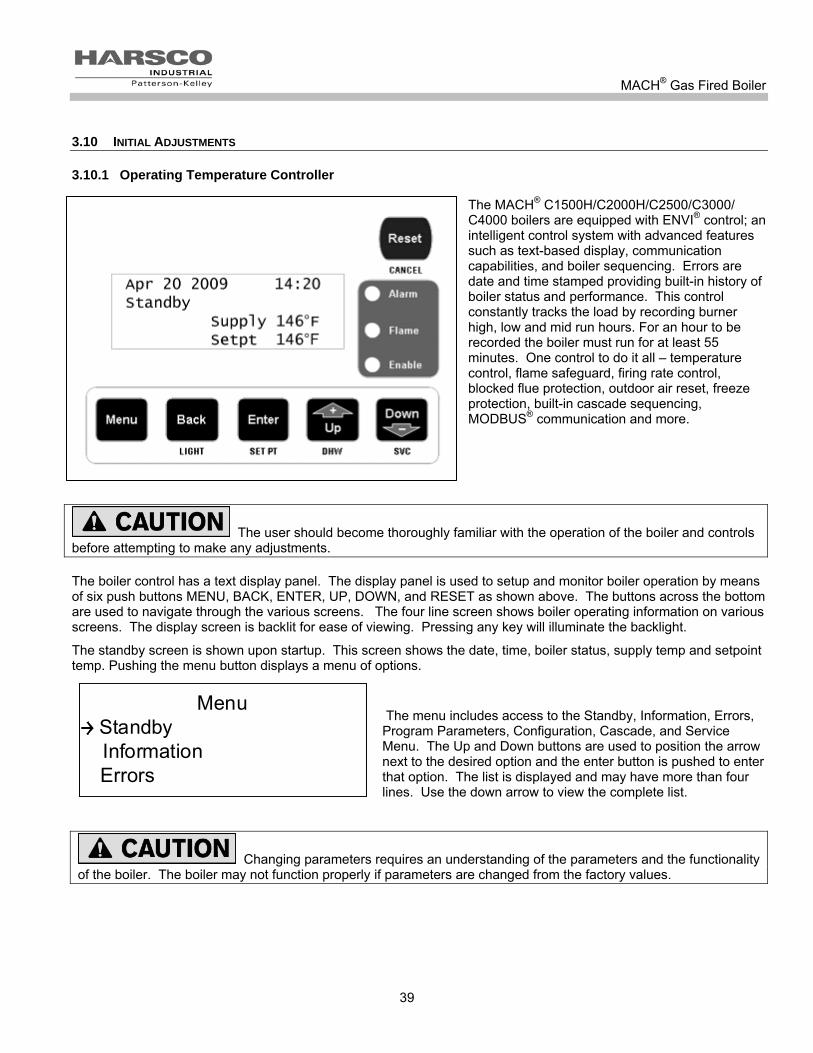
MACH® Gas Fired Boiler
39
3.10 INITIAL ADJUSTMENTS
3.10.1 Operating Temperature Controller
The MACH® C1500H/C2000H/C2500/C3000/ C4000 boilers are equipped with ENVI® control; an intelligent control system with advanced features such as text-based display, communication capabilities, and boiler sequencing. Errors are date and time stamped providing built-in history of boiler status and performance. This control constantly tracks the load by recording burner high, low and mid run hours. For an hour to be recorded the boiler must run for at least 55 minutes. One control to do it all – temperature control, flame safeguard, firing rate control, blocked flue protection, outdoor air reset, freeze protection, built-in cascade sequencing, MODBUS® communication and more.
The user should become thoroughly familiar with the operation of the boiler and controls before attempting to make any adjustments.
The boiler control has a text display panel. The display panel is used to setup and monitor boiler operation by means of six push buttons MENU, BACK, ENTER, UP, DOWN, and RESET as shown above. The buttons across the bottom are used to navigate through the various screens. The four line screen shows boiler operating information on various screens. The display screen is backlit for ease of viewing. Pressing any key will illuminate the backlight.
The standby screen is shown upon startup. This screen shows the date, time, boiler status, supply temp and setpoint temp. Pushing the menu button displays a menu of options.
The menu includes access to the Standby, Information, Errors, Program Parameters, Configuration, Cascade, and Service Menu. The Up and Down buttons are used to position the arrow next to the desired option and the enter button is pushed to enter that option. The list is displayed and may have more than four lines. Use the down arrow to view the complete list.
Changing parameters requires an understanding of the parameters and the functionality of the boiler. The boiler may not function properly if parameters are changed from the factory values.
MenuStandby Information Errors
MenuStandby Information Errors

MACH® Gas Fired Boiler
40
3.10.2 Boiler Setpoint
The factory default setpoint is 180 °F. If a different setpoint is desired, push the menu button and then select PARAMETERS from the menu. A screen opens that allows the user to view and change operating parameters (see screenshot below.)
ParametersCH settings DHW settings Boiler settings
ParametersCH settings DHW settings Boiler settings
Select the CH settings to adjust parameters related to the boilers Comfort Heat function.
CH settingsSetpoint 180°FBLR OP 1 CH mode 0
CH settingsSetpoint 180°FBLR OP 1 CH mode 0
CH settingsSetpoint 180°FBLR OP 1 CH mode 0
For example, selecting the Setpoint parameter opens up a screen that allows the setpoint to be changed.
CH settingsSetpoint Value: 180°F Range: 45°F – 185°F
CH settingsSetpoint Value: 180°F Range: 45°F – 185°F
The up or down buttons are used to adjust the CH setpoint up or down as desired. The enter button is pushed once the desired temperature is reached.
3.10.3 Other CH Parameters
Other settings include the following items:
Description Value Units
CH Setpoint 180 °F Factory adjustable from 42-185
BLR OP 1
0-3
0=boiler and pump off
1=boiler on and pump automatic
2=boiler off and pump on
3=boiler on and pump on
CH Mode 0 0-8 0 thru 8 see ENVI users guide
Hysteresis On (On Differential) 5 °F Adjustable from 0 to 22 degree’s
Hysteresis Off (Off Differential) 15 °F Adjustable from 0 to 22 degree’s
Post Pump time 30 Sec Adjustable from 0 to 2550 seconds
The above values listed are the factory settings.

MACH® Gas Fired Boiler
41
Additional CH Parameters are available and used for the various CH Modes other than mode 0, the standard Setpoint & (Thermo) Stat control mode. These modes are further described in the ENVI® Control Advanced User’s Guide.
3.10.4 Other Parameters
Other parameters include the settings for DHW (Domestic Hot Water), Boiler Settings and OEM Settings. Boiler and OEM Settings are used during the initial programming of the control and are not adjustable.
3.10.5 Additional Menu Items
In the main menu, Standby, Information, Errors, Program Parameters, Configuration, Cascade, and Service Menus are available. They are used for various functions of the boiler. These functions are described further in the ENVI® Control Advanced User’s Guide.
These menu items will be described briefly here:
STANDBY is the default screen and is shown during normal boiler operation.
The INFORMATION menu lists items that the boiler monitors such as temperatures, operating conditions, and status of switches and components.
The ERRORS menu has information about the boiler status at the time of an error.
The PARAMETERS menu allows the user to set up selected boiler functions and operating modes.
The CONFIGURATION menu covers basic display information such as language, units, date/time, etc.
The CASCADE menu is used to sequence multiple boilers (up to 24 max) in a Master/Member network system. Use of this function is described in detail in the Advanced User’s Guide.
The SERVICE menu is described below.
3.10.6 Service Menu:
Two test modes are available in the service menu.
BNR ON TEST HI LOW
BNR OFF FAN HI LOW
The first test mode allows the service technician to hold the boiler in high or low fire during firing operation so that the combustion adjustment can be performed as indicated below.
The second test mode checks the fan rate with the burner off at high speed or at low speed.
These test modes will automatically terminate after 15 minutes of inactivity or can be terminated from the display by pressing the reset button.
ServiceBNR ON Test HI LOW BNR OFF Fan HI LOW
ServiceBNR ON Test HI LOW BNR OFF Fan HI LOW
ServiceBNR ON Test HI LOW BNR OFF Fan HI LOW

MACH® Gas Fired Boiler
42
3.11 FUEL/AIR ADJUSTMENT
The gas train for MACH® C1500H/C2000H/C2500/C3000/C4000 boilers are equipped with gas/air ratio control valve and a gas safety shut off control valve, combined into one valve assembly. The valves function in series with the variable speed combustion blower to supply the correct gas air ratio for optimum firing performance and efficiency. The combustion blower speed is controlled automatically by the boiler controller. The blower speed determines the amount of air flow and the amount of suction/negative pressure at the gas valves. The gas valve adjusts gas flow to maintain the proper delivery pressure at the outlet of the valve.
NOTICE: Adjustments shall only be performed by qualified and knowledgeable installer or service agency specifically trained and certified to perform maintenance and/or startup on the Harsco Industrial, Patterson-Kelley MACH® boiler.
3.11.1 Combustion setup and adjustment
Boiler Test Mode for High and Low fire: Set the combustion using the Service Menu BNR ON TEST HI & BNR ON TEST LOW modes. These test modes should be used when checking and setting the gas safety shut off / control valves on the MACH® boiler. In this mode a heat request is required. Once the boiler cycles on, use the arrow keys to access the Service Menu and select the BNR ON TEST HI/LOW mode and push enter. Then select BNR ON TEST HI or the BNR ON TEST LOW mode and push enter. The boiler will ramp to high or low fire. NOTICE! There must be sufficient load to operate the boiler at high fire to perform the following adjustments. Start the boiler and observe proper operating parameters for the system.
The air flow is pre-set at the factory prior to shipment. Gas flow is dependent primarily on fan speed not upstream gas pressure. The automatic gas valve may have to be adjusted to obtain proper combustion readings for specific local conditions. A combustion analyzer must be used. Combustion should be set in accordance with Table 3-1.
Table 3-1 Combustion Exhaust Reading For Setting Gas Safety Shut Off / Control Valves
Fuel
Nominal High Fire Setting Low Fire Setting
Gas Pressure % O2 % CO2 % O2 % CO2
Natural Gas 7" W.C 4.8 ± 0.2 9.2 ± 0.1 5.0 ± 0.2 9.1 ± 0.1
Propane Gas 11” WC 4.8 ± 0.2 10.4 ± 0.3 5.0 ± 0.2 10.3 ± 0.3
Main gas shut off with Service port for checking incoming gas pressure

MACH® Gas Fired Boiler
43
3.11.2 Gas valve adjustment
The gas valve is located inside the cabinet. Each valve is labeled and adjusted for a specific fuel. See specific section for proper application. Check the combustion using a combustion analyzer and adjust the fuel/air ratio of the valve being used according to the procedures below. For initial startup, the boiler should be fired and the combustion should be adjusted. To adjust high fire: Required Tools: Flat head screwdriver and Combustion analyzer Start the boiler and observe proper operating parameters for the system. Set boiler to the “BNR ON TEST HI”, as described above, to achieve maximum firing rate of the boiler. Check combustion readings using the combustion analyzer. If combustion readings are not in accordance with Table 3-1, adjust as follows: Open the front panel of the boiler. Locate the automatic gas valve. Turn the orifice adjusting screw, located on the downstream side of the valve, in the direction indicated on the sticker to increase or decrease the gas flow. Increasing the gas flow decreases the combustion exhaust O2, while decreasing the gas flow increases the combustion exhaust O2. There will be a slight time delay between the adjustment and the response of the CO2/O2 measuring instrument. Adjust the settings in small increments and allow the combustion readings to stabilize before readjusting. When desired adjustments are complete, check and adjust low fire if necessary.
To adjust low fire:
Required Tools: 2.5 mm hex wrench and Combustion analyzer Start the boiler and observe proper operating parameters for the system. Set boiler to the “BNR ON TEST LOW”, as described above, to achieve minimum firing rate of the boiler. Check combustion readings using the combustion analyzer. If combustion readings are not in accordance with Table 3-1, adjust as follows: Open the front panel of the boiler. Locate the automatic gas valve. Turn the offset screw, located in the bottom center of the side of the valve, in the direction indicated on the label to increase or decrease the gas. Increasing the gas decreases the O2, while decreasing the gas increases the O2. There will be a slight time delay between the adjustment and the response of the CO2/O2 measuring instrument. Adjust the settings in small increments and allow the combustion readings to stabilize before readjusting. When desired adjustments are complete, check and adjust hi fire if necessary.
Gas Valve
High Fire
Low Fire Adjust

MACH® Gas Fired Boiler
44
3.11.3 Checking Flame Signal
Using the control panel, enter the information mode and scroll down view the flame signal. This shows μA when the boiler is firing and shows 0μA when the boiler is not firing. 7-8μA is a strong flame signal.
4 OPERATION 4.1 GENERAL
4.1.1 Control front panel
Become familiar with the basic operation of the boiler. The interior of the front door shows the boiler Operating Instructions.
4.1.2 Factory Tests
Safe lighting and other performance criteria were met with the gas manifold and control assembly provided on this boiler when the boiler underwent factory tests specified in ANSI Z21.13/CSA 4.9, latest edition. (See "Factory Fire test" label located on the back left side of the boiler.)
Do not use this boiler if any part has been under water. Immediately call a qualified service technician to inspect the boiler and to replace any part of the control system and any gas control which has been under water.
TB2 120VAC high voltage terminal connections
TB1 low voltage terminal connections
ENVI control keypad/display
Power switch and contol circuit breakers if applicable
ENVI control relay board Liquid Level
control or low water cut off
ENVI control
Manual reset high water temperature limit
Air and back pressure safety switches

MACH® Gas Fired Boiler
45
4.2 NORMAL LIGHTING AND SHUT-DOWN PROCEDURES
Do not use this boiler if any part has been under water. Immediately call a qualified service technician to inspect the boiler and to replace any part of the control system and any gas control which has been under water.
4.2.1 Lighting Procedures
1. Make sure the system is filled with water and water is circulating in the system. Turn on electrical supply and open the gas supply valves to the boiler.
2. Turn the on/off switch to the on position. If an error is indicated, see Section 5.5 of this manual to troubleshoot the problem and take the necessary corrective action before proceeding.
3. Set the desired high temperature limit and operating temperature. The controller will now complete the automatic firing sequence.
4.2.2 Fuel Selection (Dual Fuel Only)
1. Before switching fuels, ensure that the boiler is turned off. 2. Ensure that both fuel lines are correctly connected to the boiler. 3. Make sure the ball valve for the desired fuel is open. 4. Use the fuel selector switch, located inside the left control panel door near the top of the boiler, to select the
desired fuel. The fuel selector switch has three positions: propane, off and natural gas. 5. Start the boiler according to 4.2.1
NOTICE! The dual fuel selector switch is a hesitation type switch. When switching fuels you must release the switch in the “OFF” position before switching to the other fuel. Additionally, It is recommended to close the ball valve of the non-selected fuel.
4.2.3 Normal Shut Down Procedures
1. Turn the on/off switch to the off position.
2. Close all manual gas valves.
FUEL SELECTOR SWITCH
Fuel Selection Switch

MACH® Gas Fired Boiler
46
4.3 EMERGENCY SHUT-OFF
Should overheating occur or the gas supply fail to shut off, do not turn off or disconnect the electrical supply to the pump. Instead, shut off the gas supply at a location external to the appliance.
AVERTISSEMENT! En cas de surchauffe ou si l’admission de gaz ne peut être coupée, ne pas couper ni débrancher l’alimentation électrique de la pompe. Fermer plutôt le robinet d’admission de gaz à l’extérieur de l’appareil.
NOTICE! Manual gas shut off valves will be located either on the top of the boiler or on the back of the boiler depending on your model boiler. 4.4 TYPICAL BOILER OPERATING CONDITIONS
Model Number
Input Rating
(BTU/Hr)
Voltage
Total Amperage
Gas Flow Rate (CFH)
Natural Gas
1030 Btu/cu. ft.
LP Gas
2500 Btu/cu. ft.
Output Capacity (Btu/hr)
C1500H 1,500,000 120/1/60 Less than 15 1456 600 1,440,000
C2000H 2,000,000 120/1/60 Less than 15 1942 800 1,920,000
C2500 2,500,000 120/1/60 Less than 17 2427 1000 2,375,000
C3000 3,000,000 208-240/3/60
Less than 20 2913 1200 2,850,000
480/3/60 Less than 20
C4000 4,000,000 208-240/3/60
Less than 20 3689 1520 3,800,000
480/3/60 Less than 20
NOTICE! The heat exchanger is constructed and stamped for 125 psig maximum operating pressure and 220ºF maximum temperatures. The maximum setpoint is 185ºF.
Manual gas shut off valve

MACH® Gas Fired Boiler
47
5 MAINTENANCE 5.1 MAINTENANCE AND INSPECTION SCHEDULE
This schedule applies when the boiler is in use. Verify proper operation after servicing.
Proper lockout/ tag out procedure must be employed when servicing this unit.
Label all wires prior to disconnection when servicing controls. Wiring errors can cause improper and dangerous operation.
ATTENTION. Au moment de l’entretien des commandes, étiquetez tous les fils avant de les débrancher. Les erreurs de câblage peuvent nuire au bon fonctionnement et être dangereuses.
Use care when reassembling main gas line to assure all connections are tight.
Use care when servicing boiler in order to prevent the accumulation of gas in or around the combustion chamber.
Determine the cause of any lockout or errors before resetting the boiler. If able to determine cause of lockout, then appropriate corrective action should be taken. If unable to determine cause of the problem, call a qualified service technician.
Verify proper operation after operation servicing.
AVERTISSEMENT! S’assurer que l’appareil fonctionne adéquatement une fois l’entretien terminé.
5.1.1 Daily
Observe operating temperature and general conditions. Make sure that the flow of combustion and ventilating air to the boiler is not obstructed. Determine the cause of any service codes or lockouts on the display panel. Observe any unusual noises or operating conditions and make the necessary corrections. Notify responsible individuals for required corrective action or repair.
Check daily to be sure that the boiler area is free and clear of any combustible materials, including flammable vapors and liquids.
5.1.2 Weekly
Observe the conditions of the main flame. A normal high fire flame is mostly blue, while at low fire the burner will be blue with some yellow orange.
MACH® Gas Fired Boiler
48
Correct air adjustment is essential to the efficient operation of this boiler. Ensure that the flow of combustion and ventilation air is not obstructed. If an adjustment in the combustion appears necessary, the flue gas composition should be checked with a carbon dioxide (CO2) or oxygen (O2) analyzer and compared to the values stated in Table 3-1 of section 3.11.2.1. If an adjustment in the combustion is necessary, call a qualified and knowledgeable installer or service agency that has been trained on the Harsco Industrial, Patterson-Kelley MACH® boilers.
5.1.3 Monthly
1. Using the control panel, enter the information mode and scroll down view the flame signal. This is measured in micro-amps of flame conductivity.
2. Test high-limit Control. Refer to Section 3.9.3.
3. Test operating temperature controls by reducing or increasing temperature setting as necessary to check burner operation.
4. Test the low water level cut-out. Refer to Section 3.9.2.
5. Test low gas pressure switch. Refer to Section 3.9.4.
6. Check the condensate drain system. Clean and flush as necessary.
Installation and service must be performed by a qualified and knowledgeable installer or service agency that has been trained on the Harsco Industrial, Patterson-Kelley MACH® boilers.
5.1.4 Semi-Annually (required for boilers operated year round)
In addition to the recommended monthly service:
1. Clean burner of any accumulated dust or lint. See Section 5.2 on "Cleaning the Burner."
2. Inspect burner for any signs of deterioration or corrosion. Replace immediately if deterioration or corrosion is evident.
3. Check the pH level of the system fluid.
4. Inspect and clean the condensate system and check for leaks. If a condensate neutralization kit is present, open the lid and inspect the limestone rocks. If they are absent or have been significantly worn away, replace them with new limestone rocks. Use hi-calcium (or pure) limestone.
Note: replacement media (rocks) can be ordered through you local HIP-K Representative.
Installation and service must be performed by a qualified installer or service agency that has been trained on the Harsco Industrial, Patterson-Kelley MACH® boiler.
The blower motor is permanently lubricated and does not require periodic lubrication.
5.1.5 Annually
In addition to the recommended monthly and semi-annual service:
1. Inspect and clean the inlet screen of any accumulated dust or lint.
2. Check burner and clean off any soot or foreign material that may have accumulated. See Section 5.2 on "Cleaning the Burner." Check for corrosion of the burner and its parts. If there is evidence of deterioration or corrosion, replace immediately. Inspect combustion chamber when the burner is removed for inspection. Note any signs of deterioration. Clean as necessary.
3. Inspect and clean heat exchanger. Remove the various covers to inspect the flue gas passageways. Clean the combustion side casting pins by flushing with clean water. Do not use any cleaning agents or solvents. Do not use soap. Be sure to inspect the condensate collection pan that is the lowest part of the heat exchanger. Then empty out the condensate trap of any debris.
4. Replace the igniter, flame rod and gaskets as applicable

MACH® Gas Fired Boiler
49
Note: You can order an Annual Maintenance kit from your local HIPK Representative.
5. Drain and flush the water side of the heat exchanger as required (separate from system flush) using clean water only.
6. Inspect and clean the condensate system and check for leaks. If a condensate neutralization kit is present, open the lid and inspect the limestone rocks. If they are absent or have been significantly worn away, replace them with new limestone rocks. Use hi-calcium (or pure) limestone.
7. Examine the venting system at least once a year. Refer to the vent manufacturer's instructions for requirements in addition to those listed below.
a. Check all joints and pipe connections for tightness.
b. Check pipe for corrosion or deterioration. If any piping needs replacing, do so immediately.
c. Inspect and clean any screens in the vent terminal
8. Qualified service personnel should thoroughly inspect the heating system and correct any problems prior to re-starting the boiler.
9. Perform combustion analysis and readjust as necessary according to table 3-1 and section 3.10.4. It is recommended that a copy of this report is filed for future reference.
10. Perform a leak test of the gas valves in accordance with the manufacturer's instructions.
11. Test pressure safety relief valve.
Installation and service must be performed by a qualified installer or service agency that has been trained on the Harsco Industrial, Patterson-Kelley MACH® boiler.
Note: Annual Maintenance kits can be ordered through you local HIP-K Representative.
Note: In certain applications of low setpoint for long periods of time it is recommended to wash the combustion side of the heat exchanger.
5.2 CLEANING THE BURNER
1. Lockout/tag out gas supply to the boiler.
2. Lockout/tag out electrical power to the boiler.
3. Open the front and side doors of the boiler.
4. Locate the blower and burner transition pieces that are directly in the front of the boiler. See 6.2.4 for illustration of components.
5. Remove the hardware connecting the blower transition piece to the burner transition piece. The blower transition piece is supported and remains in place.
6. Remove the hardware holding the burner transition piece to the studs on the front of the boiler.
7. Pull out the burner transition piece with the 2 gaskets and set aside. Inspect the gaskets and replace if damaged.
8. Carefully remove the burner. Rinse the burner with water. For propane or dual fuel boilers using propane it may be necessary to use a mild soap or detergent for cleaning the burner.
9. Reassemble being sure to install all gaskets and seals properly.
10. Then run the fan in high within the service mode to dry off the burner before firing.

MACH® Gas Fired Boiler
50
5.3 REMOVING THE HEAT EXCHANGER
Heat Exchanger is heavy and may cause injury if improperly handled. Removal of the heat exchanger should be performed only by knowledgeable and experienced personnel.
5.4 AFTER ALL REPAIRS OR MAINTENANCE
1. Follow "Pre-Start Check List" (Section 3.8) and all "Safety Checks" (Section 3.9).
2. Check gas pressure. (Section 3.11.2.1). Ensure proper operation of unit
3. Perform combustion check. Adjust gas flow if necessary. (Section 3.11.2..2). 5.5 SEQUENCE OF OPERATION
1. When the Boiler On/Off switch is turned on, power is provided through a circuit breaker to the boiler control and
the combustion blower.
2. If the high gas, low gas or low water level control is open, the boiler control locks out and displays an error.
3. When the water temperature is below the boiler control setpoint minus the hysteresis (On Differential), a heat request is generated.
4. Provided all limits are made, the boiler will attempt to start.
5. The controller checks that the air pressure switch is open indicating no airflow. The blower is driven towards the prestart fan speed. When the air pressure switch closes, the 25 second pre-purge time is started. After the pre-purge, the blower is driven to the ignition speed.
6. A trial for ignition begins. The sequence of events is illustrated graphically below.
7. After ignition, the fan may be driven to low fire before the boiler is released to modulation.
8. The control modulates the firing rate between low and high fire to maintain the desired outlet water temperature.
9. The burner will continue firing until the outlet water temperature reaches set point plus hysteresis (Off Differential). At this temperature the fuel supply is shut off and the combustion air fan continues to run for a 30 second post-purge.
10. When the water temperature is reduced by the load on the system, a heat request is generated. The operating sequence will recycle to step 4.
0 1 2 3 4 5 6 7
Spark
Gas Valve
Flame Detection
Seconds
Fan
*Flame must be detected at T = 6 seconds
*
Ignition Sequence Timing
0 1 2 3 4 5 6 7
Spark
Gas Valve
Flame Detection
Seconds
Fan
*Flame must be detected at T = 6 seconds
*
Ignition Sequence Timing
NOTICE! Once the boiler begins the ignition sequence, the firing sequence will continue until main flame is reached regardless of heat request. The sequence can be interrupted by turning the power switch off.

MACH® Gas Fired Boiler
51
5.6 TROUBLESHOOTING
If any “Manual Reset” limit device trips, DO NOT reset without determining and correcting the cause. (Manual Reset Limits include: Flame safeguard, high or low gas pressure, high temperature limit, stack temperature, low water level.)
The ENVI® control will display text based error descriptions to indicate any problems with the boiler. There are two types of lockouts the control may experience: manual reset lockouts requiring an operator to press the reset button, and automatic reset lockouts that will self reset when the error condition clears. A listing of errors and their service codes is included at the end of this section.
Should the unit fail to operate, call a qualified service technician to troubleshoot the problem and implement corrective actions.
5.6.1 The Loss of Power
In the event of a power failure, the display panel is not illuminated and the entire system is de-energized, closing all automatic valves and halting all boiler operations. When power is restored the sequence of operation will resume at Step 4. If any error/lockout is present when the power is lost, the control will retain that error/lockout and display the error/lockout when the power is restored.
5.6.2 Loss of Water Level
The low water switch opens when there is insufficient water in the boiler. Lockout A43 LOW WATER LEVEL is shown on the display, the burner operation is interrupted, and the boiler locks out. When the correct water level is re-established, and the control reset button is pressed, the boiler will reset and will start the sequence at Step 4.
Note: There is a red LED on the liquid level control board indicating when the probe is sensing water level.
5.6.3 Low Gas Pressure
The low gas pressure switch opens when there is (or has been) insufficient gas pressure available for proper operation of the boiler. If an external gas-supply shut-off valve is closed for any reason, a low gas condition will result. Locking A31 LOW GAS PRESSURE is shown on the display, the burner operation is interrupted, and the boiler locks out. When proper gas pressure is restored, and the control reset button is pressed, the boiler will reset and will start the sequence at Step 4. This switch opens below 2”W.C.
5.6.4 High Gas Pressure
The high gas pressure switch opens when there is excessive gas pressure for the proper operation of the boiler Locking A30 HIGH GAS PRESSURE is shown on the display, the burner operation is interrupted, and the boiler locks out. When proper gas pressure is restored, and the control reset button is pressed, the boiler will reset and will start the sequence at Step 4. This switch opens above 2”W.C.
On Duel Fuel Boilers
In addition, A30 HIGH GAS PRESSURE error could be due to both gas valves being open. If you observe that both gas valves are powered simultaneously, the boiler will show A30 HIGH GAS PRESSURE error as indicated above, If this error is observed, call a qualified service technician for assistance.
5.6.5 High Water Temperature
When the boiler water has exceeded both the operating and high-limit temperature the high limit switch opens, and Locking A03 HIGH LIMIT is shown on the display. When the water temperature falls below the high-limit temperature, the boiler will remain locked out until the water high limit switch is manually reset and the front panel reset button is pressed. Once reset, the control will restart the sequence of operation at Step 4.

MACH® Gas Fired Boiler
52
5.6.6 Low Air
If the display panel indicates Locking A34 AIR SWITCH NOT OPEN or Locking A35 AIR SWITCH NOT CLOSED this indicates improper airflow through the boiler. Check the hoses leading to the air switches. Verify proper blower operation. An air switch error does not necessarily mean that the air switch is defective.
When A34 AIR SWITCH NOT OPEN is shown on the display, check that the air switch is open when the fan is off. Check that there is no air flow through the boiler when the fan is off. Check for too much negative within the vent or a blower that has failed running when it should not be.
When A35 AIR SWITCH NOT CLOSED is shown on the display, check that the air switch is closed when the fan is running. If the air switch does not close within 5 minutes during purge, the boiler locks out. Check that the burner, heat exchanger and condensate trap is clean ("Cleaning the Burner," Section 5.2) and that there are no obstructions to airflow in the intake or exhaust ducts.
5.6.7 Flame Failure
In the event of a flame failure, the main fuel valves are de-energized and a manual reset lockout occurs.
Locking A01 IGNITION FAILURE or Lockout A02 FLAME FAILURE is shown on the display. The cause of flame failure must be diagnosed and repaired before the control is reset.
When A01 IGNITION FAILURE is shown on the display, the boiler did not light during a trial for ignition. Check that the spark, electrode, ignition wire, and gas valve are functioning properly.
When A02 FLAME FAILURE is shown on the display, the boiler lost the flame during run. Check that the combustion is setup properly, the gas pressure is correct, as well as other combustion parameters.
5.6.8 Flame Error
Locking A19 LATE FLAME
Blocking E20 FALSE FLAME
These errors signify flame error. This may be caused by a failed or leaky gas valve or a flame detector malfunction. If gas valve leakage is suspected, the unit must be isolated by turning off the main gas supply line. Qualified and knowledgeable service personnel must be called to evaluate and repair/replace the failed parts. Verify that the igniter cable is not grounding out or there are any cracks within the electrode creating a short circuit.
5.6.9 Stack Problem
E34 BLOCKED_FLUE_indicates that the high exhaust back pressure switch has tripped. This may be caused by a blocked stack, a blocked air inlet, or a blocked condensate system or a high negative within the vent. When the blockage is removed, the boiler will automatically restart.
A comprehensive listing of the locking and blocking error codes is provided on the next page.

MACH® Gas Fired Boiler
53
5.7 MANUAL RESET ERROR CODES-A##A (OR LOCKING ERROR CODES)
A Code Error Int. nr Description
A01 IGNIT ERROR 1 Three unsuccessful ignition attempts in a row
A02 TOO MANY FLAME FAILURES 24 Three times flame was lost during on demand
A03 T MAX LOCK ERROR 18 Overheat stat is open
A05 GV RELAY ERROR 5 Problems with gas valve relay= internal hardware error (pump not running)
A06 SAFTEY RELAY ERROR 6 Problems with gas valve relay = internal hardware error (pump not running)
A09 RAM ERROR 9 Internal software error
A09 FLAG BYTE INTEGRITY ERROR 27 Internal software error
A09 AD HI CPL ERROR 28 Internal software error
A09 AD LO CPL ERROR 29 Internal software error
A09 REGISTER ERROR 33 Internal software error
A10 E2PROM ERROR 12 No communication with E2prom
A12 WRONG EEPROM SIGNATURE 10 Contents of Eprom is not up-to-date
A13 STATE ERROR 13 Internal software error
A14 ROM ERROR 14 Internal software error
A15 15MS XRL ERROR 16 Internal software error
A16 20 MS XLR ERROR 22 Internal software error
A18 STACK ERROR 19 Internal software error
A19 FLAME OUT TOO LATE ERROR 20 Flame still present 10 sec. after closing the gas valve
A20 FLAME ERROR I 21 Flame detected just before gas valve opened
A30 HIGH GAS PRESSURE ERROR 32 Gas pressure is to high
A31 LOW GAS PRESSURE ERROR 31 Gas pressure is to low
A32 41MS ERROR 23 Internal software issue
A33 FAN ERROR 8 Fan deviation more than300 rpm longer than 1 minute (when fan speed > 4200 rpm this error is ignored)
A34 AIR PRESS SW NOT OPEN ERROR 25 Air pressure switch doesn’t open within 30 seconds
A35 AIR PRESS SW NOT CLOSED ERROR 26 Air pressure switch doesn’t close within 30 seconds
A37 UV SENSOR BROKEN 11 UV scanner not functioning
A38 MOD BACK DIFF ERROR 4 Large difference between return and flow temperatures
A39 RAPID RISE ERROR LOCK RET 15 Return temperature rise too rapidly
A40 RAPID RISE ERROR LOCK FLOW 7 Flow temperature rise to rapidly
A41 RAPID RISE ERROR LOCK HX 17 Heat exchanger rise to rapidly
A43 LOW WATER CUTOFF ERROR 30 Water pressure is to low
A44 FLAME CKT ERROR 34 Ionization (flame rod)wire lost for more than 15 seconds
NOTICE! When an Internal Error occurs, as identified above, the failure is internal to the ENVI® control and replacement of the ENVI® control is required. A qualified service technician must replace the ENVI® control.

MACH® Gas Fired Boiler
54
5.8 AUTO-RESET ERROR CODES-E## (OR BLOCKING ERROR CODES)
Code ENVI® Control Display Lockout Description
E01 T FLOW OPEN 53 Flow sensor not connected
E02 T RETURN OPEN 54 Return sensor not connected
E03 T FLUE OPEN 59 Flue sensor not connected
E04 T DHW OPEN 57 DHW sensor not connected
E05 T HX OPEN 58 Heat exchanger sensor not connected
E06 HEADER SENSOR OPEN 70 Header sensor on IF board not connected
E11 T FLOW SHORTED 61 Flow sensor shorted
E12 T RETURN SHORTED 62 Return sensor shorted
E13 T FLUE SHORTED 67 Flue sensor shorted
E14 T DHW SHORTED 65 DHW sensor shorted
E15 T HX SHORTED 66 Heat exchanger sensor shorted
E16 HEADER SENSOR SHORTED 71 Header sensor on IF board shorted
E18 PHASE ERROR 46 Phase and neutral of supply voltage mains are reversed
E19 E2PROM READ ERROR 0 Problems from reading from or writing to E2prom
E20 FLAME ERROR 2 74 False flame detected
E21 LOW FLOW/ILK 73 Low flow or interlock error
E22 WD 50HZ ERROR 45 No earth ground connected or internal hardware error
E23 NET FREQ ERROR 47 Main supply voltage frequency differs more than 2% from 60HZ
E24 FAULTY EARTH ERROR 48 Faulty earth ground to boiler
E30 FLUE GAS ERROR 39 Flue gas sensor is above setpoint plus differential
E32 RETURN TEMP ERROR 42 Return temperature is above 90 degrees
E34 BLOCKED FLUE ERROR 41 Flue gas outlet is restricted or blocked
E41 REVERSE FLOW ERROR 43 Supply and return temp are reversed
E42 WD COMMUNICATION ERROR 49 Internal hardware error
E44 FLAME CKT FAULT 40 Ionization or flame rod wire is lost
E45 REFHI TOO LO ERROR 35 Internal hardware error
E46 REFHI TOO HI ERROR 36 Internal hardware error
E47 REFLO TOO LO ERROR 37 Internal hardware error
E48 REFLO TOO HI ERROR 38 Internal hardware error
E 49 RAPID RISE HX ERROR BLOCK 51 Heat exchanger temperature rise to rapidly (blocking)
E50 RAPID RISE ERROR BLOCK 72 Flow temperature rise too rapidly (blocking)
E51 RESET BUTTON ERROR 68 Reset button pressed more than 7 times within 1 minute
E52 APPLIANCE SELECTION ERROR 50 Appliance and resistor do not match at start up
E54 IF COMMUNICATION FAILURE 69 No communication with interface board

MACH® Gas Fired Boiler
55
6 PARTS/TECHNICAL SUPPORT Spare parts and replacement parts can be ordered from Harsco Industrial, Patterson-Kelley by calling toll free (877) 728-5351. The fax number is (570) 476-7247. Refer to the parts list shown on the assembly drawing provided in this manual. Technical information is also available at the above number and at the Harsco Industrial, Patterson-Kelly website www.harscopk.com.
Use of Non-Factory Authorized replacement parts are not recommended for this equipment. All control components are engineered for safety and are designed to work in unison with each of the other components. Use of non-factory authorized replacement parts jeopardizes the functionality of the safety features as well as the performance of the boiler.
When ordering replacement parts please have the model number and serial number of your boiler available. Typical schematic drawings are shown on the following pages. Drawings specific to your particular boiler can also be supplied by your local Harsco Industrial, Patterson-Kelley representative.

MACH® Gas Fired Boiler
56
6.1 WIRING DIAGRAMS
6.1.1 MACH® Boiler C1500H/C2000H Wiring Diagram

MACH® Gas Fired Boiler
57
6.1.2 MACH® C2500 Wiring Diagram
East S
troudsburg, PA
183015
70-476-7261
ww
w.harsco
pk.com
MA
CH
C-2500
EN
VI C
ontrol
®2
640
000
055
RE
V. 0.4
TM
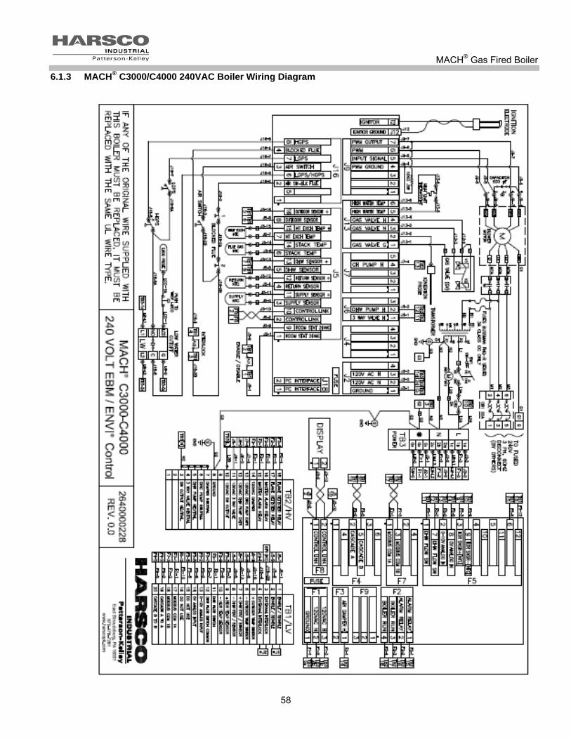
MACH® Gas Fired Boiler
58
6.1.3 MACH® C3000/C4000 240VAC Boiler Wiring Diagram

MACH® Gas Fired Boiler
59
6.1.4 MACH® C3000/C4000 480VAC Wiring Diagram

MACH® Gas Fired Boiler
60
6.1.5 MACH® C1500H GG/C2000H GG Dual Fuel Boiler Wiring Diagram
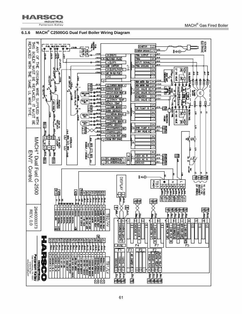
MACH® Gas Fired Boiler
61
6.1.6 MACH® C2500GG Dual Fuel Boiler Wiring Diagram

MACH® Gas Fired Boiler
62
6.1.7 MACH® C3000GG/C4000GG 240VAC Dual Fuel Boiler Wiring Diagram

MACH® Gas Fired Boiler
63
6.1.8 MACH® C3000GG/C4000GG 480VAC Dual Fuel Boiler Wiring Diagram

MACH® Gas Fired Boiler
64
6.1.9 MACH® C1500HGG/C2000HGG/C2500GG/C3000GG/4000GG Dual Fuel Control Wiring

MACH® Gas Fired Boiler
65
6.1.10 Terminal Block Assignments – Power Block
The MACH® C1500H/C2000H/C2500 boiler power is connected on the front top right side in Terminal box 2 or TB2 on terminals 1, 2,and 8. Pictured below
POWER INPUT JUNCTION BOX The MACH® C3000/C4000 boiler power block is located in the junction box in the front of the boiler, at the lower left corner (pictured to the right). This junction box houses the transformer, the fuses, the power block terminal strip circuit breakers, and the blower relay. The three space terminal strip circuit breakers are mounted on DIN rail and are for connection of the three power wires. There is an additional space on the DIN rail for a ground connection. This boiler requires either 208-240 V, three phase, 60 Hz or 480 V, three phase, 60 Hz. The boiler requires a dedicated ground wire. Do not ground through the conduit.
Field service power connections for C3000 and C4000
Field service power connections for C1500H/C2000H and C2500

MACH® Gas Fired Boiler
66
6.1.11 Terminal Block Assignments – High Voltage Circuit (TB2)
Terminal Number
Label Description
1 120VAC Line FOR C1500H/C2000H/C2500. NOT USED ON THE C3000/C4000
2 120VAC Neutral FOR C1500H/C2000H/C2500. NOT USED ON THE C3000/C4000
3 120VAC Neutral Neutral for use with TB2-10, Switched Output
4 120VAC Neutral Neutral for use with TB2-11, 3 Way Valve
5 120VAC Neutral Neutral for use with TB2-12, DHW Pump Contactor
6 120VAC Neutral Neutral for use with TB2-13, CIRC Pump Contactor
7 120VAC Neutral Neutral for use with TB2-14, Damper Output
8 GROUND GROUND
9 GROUND GROUND
10 120V AC SW OUTPUT
120V AC output when boiler is switched on (0.5 amp max)
11 120V AC 3 WAY VALVE
120V AC output during CH Mode. 3 way valve is normally closed (not powered) for DHW, and powered open for CH Mode.
12 120V AC DHW PUMP CNTR
120V AC output when boiler is in DHW Mode (pilot duty only)
13 120V AC CIRC PUMP CNTR
120V AC output when boiler is in CH Mode (pilot duty only)
14 120V AC DAMPER RELAY
120V AC output when boiler is enabled (pilot duty only)
15 MASTER ALARM RELAY
This circuit closes when the boiler is in a manual resettable alarm state Dry contacts normally open
16 MASTER ALARM RELAY
17 FLAME DETECTED RELAY
This circuit closes when the boiler control is seeing flame Dry contacts normally open
18 FLAME DETECTED RELAY
NOTICE! Pilot duty rated loads are for switching purposes only. no load amperage over 0.5 amps VAC

MACH® Gas Fired Boiler
67
6.1.12 Terminal Block Assignments – Low Voltage Circuit (TB1)
Terminal Number Label Description
1 ENABLE / DISABLE Boiler Enable, Contact Closure.
DO NOT ENERGIZE. 2 ENABLE / DISABLE
3 EXTERNAL INTERLOCK External Limit, Contact Closure.
DO NOT ENERGIZE. 4 EXTERNAL INTERLOCK
5 OUTDOOR TEMP SENSOR Outdoor temperature sensor
6 OUTDOOR TEMP SENSOR
7 DHW STAT OR SENSOR Domestic Hot Water sensor or thermostat
8 DHW STAT OR SENSOR
9 HEADER TEMP SENSOR Header temperature sensor
10 HEADER TEMP SENSOR
11 DHW FLOW SWITCH Domestic Hot Water flow switch
12 DHW FLOW SWITCH COMMON DHW flow switch indicates potable water flow/usage
13 0-10V ANALOG INPUT Variable Input (VDC) for remote control of boiler (+)
14 0V ANALOG INPUT 0V for use with TB1-13 (-)
15 For Future Use Not Used
16 For Future Use
17 MODBUS COM 1A Modbus connection to boiler
18 MODBUS COM 1B
19 CASCADE A TO A Cascade connection between boilers
20 CASCADE B TO B

MACH® Gas Fired Boiler
68
Before making any electrical connections to the boiler, verify that the transformer is properly configured for 208VAC, or 240VAC, or 480VAC, three phase, 60 hertz service. Do not reconfigure for any other voltage. Improper configuration of the transformer could result in serious injury or death. NOTICE! Check for correct transformer wiring on the C3000/C4000 boilers
6.1.13 MACH® C3000/C4000 208 VAC, three phase, 60 hertz Transformer Diagram
6.1.14 MACH® C3000/C4000: 240 VAC, three phase, 60 hertz Transformer diagram
MACH® Gas Fired Boiler
69
6.1.15 MACH® C3000/C4000: 480 VAC, three phase, 60 hertz Transformer diagram
6.2 BOILER PARTS LIST
6.2.1 Main Assembly MACH® C1500H/C2000H Natural Gas (NG), Propane (P) and Dual Fuel (GG) boilers
1
2 3
4
5
6
7
8
9
1. Boiler supply 2. Boiler return 3. Nat. gas inlet 4. LP gas inlet 5. Relief valve 6. Condensate drain 7. Boiler drain 8. Combustion air inlet 9. Exhaust vent
Back of boiler Side of boiler
Note: There will be either one or two gas line connections depending on which boiler model
you have.

MACH® Gas Fired Boiler
70
6.2.2 Main Assembly MACH® C2500/C3000/C4000 Natural Gas, Propane and Dual Fuel (GG) Boilers
NOTICE! For a MACH® C2500GG/C3000GG, the top connection is natural gas and the rear connection is propane or LP gas. For a MACH® C4000GG, the top connection is propane or LP gas and the rear connection is natural gas.
Back of Boiler Side of boiler
1. Boiler supply 2. Boiler return 3. Nat. gas inlet (see note below) 4. LP gas inlet (see note below) 5. Relief valve 6. Condensate drain 7. Boiler drain 8. Combustion air inlet 9. Exhaust vent
1
2
3&4
3&4
5
6 7
8
9

MACH® Gas Fired Boiler
71
6.2.3 Control Panel for MACH® C1500H/C2000H/C2500/C3000/C4000
Mark Description
1 Terminal Block 1 (TB1)
2 Air Switch
3 High Exhaust Back Pressure Switch (HEBP)
4 High Temperature Limit
5 ENVI® Control Main Board
6 Low Water Cut Off (LWCO)
7 On/Off Switch
8 5 Amp Circuit Breaker
9 ENVI® User Interface/Display Screen
10 Terminal Block 2 (TB2) 120 V
11 ENVI® Control Interface relay Board
Below is for cC3000/C4000 only
12 Main Power Input Terminals
13 Fuses
14 Power Transformer
15 Motor Relay
111
2
3
45 6 7
8
9
10

MACH® Gas Fired Boiler
72
6.2.4 Control Panel for MACH® C1500HGG/C2000HGG/C2500GG/C3000GG/C4000GG
Mark Description
1 Terminal Block 1 (TB1)
2 Air Switch
3 High Exhaust Back Pressure Switch (HEBP)
4 High Temperature Limit
5 ENVI® Control Main Board
6 Low Water Cut Off (LWCO)
7 On/Off Switch
8 5 Amp Circuit Breaker
9 ENVI® User Interface/Display Screen
10 Terminal Block 2 (TB2) 120 V
11 ENVI® Control Interface Board
11A Fuel selector switch
12 Main Power Input Terminals
13 Fuses
14 Power Transformer
15 Motor Relay
C3000/C4000 only

MACH® Gas Fired Boiler
73
6.2.5 MACH® C1500H/C2000H Heat Engine
Mark Description
1 Outlet Water Victaulic Connection
2 Outlet Water Manifold
3 Pressure Relief Valve
4 Heat Exchanger Sectional Castings
5 Inlet Water Victaulic Connection
6 Manual Drain valve
7 Condensate Collector
8 Inlet Water Manifold
9 Ignition Assembly
10 Burner
11 Burner Transition Piece
12 Burner Gasket
13 Ignition Electrode
14 Blower to burner hood gasket
14

MACH® Gas Fired Boiler
74
6.2.6 MACH® C2500/C3000/C4000 Heat Engine
Mark Description
1 Outlet Water Victaulic Connection
2 Outlet Water Manifold
3 Pressure Relief Valve
4 Heat Exchanger Sectional Castings
5 Inlet Water Victaulic Connection
6 Manual Drain valve
7 Condensate Collector
8 Heat Exchanger Sectional Castings
9 Inlet Water Manifold
10 Ignition Assembly
11 Burner
12 Burner Transition Piece
13 Burner Gasket
14 Ignition Electrode

MACH® Gas Fired Boiler
75
6.2.7 MACH® C1500H/C2000H Natural Gas Train
NOTICE! For Propane Gas, parts description and general location are the same.
6.2.8 MACH® C1500H GG/C2000H GG Dual Fuel Gas Train
Mark Description
1 Burner
2 Burner transition piece
3 Blower
4 Venturi
5 Primary Manual shut off gas valve with service port
6 Secondary Manual shut off gas valve
7 Propane or Natural automatic gas valve
8 High gas pressure switch
9 Low gas pressure switch
Mark Description
1 Burner
2 Burner transition piece
3 Blower
4 Venturi
5 Primary Manual shut off gas valve with service port
6 Secondary Manual shut off gas valve
7 Propane or Natural automatic gas valve
8 High gas pressure switch
9 Low gas pressure switch
Mark Description
1 Burner
2 Burner transition piece
3 Blower
4 Venturi
5 Propane gas Manual shut off gas valve with service port
6 Natural gas Manual shut off gas valve
7 Propane Gas automatic valve
8 Natural Gas automatic valve
9 Natural Gas Low pressure switch
10 Natural Gas High pressure switch
11 Propane Gas Low pressure switch
12 Propane Gas High pressure switch
Mark Description
1 Burner
2 Burner transition piece
3 Blower
4 Venturi
5 Primary Manual shut off gas valve with service port
6 Secondary Manual shut off gas valve
7 Propane or Natural automatic gas valve
8 High gas pressure switch
9 Low gas pressure switch
10 Propane Gas venturi inlet
11 Natural Gas venture inlet
NOTE: Notice propane and natural gas venturi connection. Visual Identification can
confirm configuration.
1 2 3
4
5
6
7
8 9
1 2 3
4
5
6
7
8
9
10
11 12
10
11

MACH® Gas Fired Boiler
76
6.2.9 MACH® C2500/C3000 Natural Gas Train
NOTICE! For Propane Gas, parts description and general location are the same.
Mark Description
1 Burner
2 Burner Transition Piece
3 Blower Transition Piece
4 Blower
5 Venturi
6 Secondary Manual Gas Shutoff
7 Natural automatic gas valve
8 Main Gas Shutoff Valve with test port
9 Natural Gas high Pressure Switch
10 Natural Gas Low Pressure Switch
11 High Exhaust Backpressure Switch
1
2
3
4
5
6
7
8
9
10
11

MACH® Gas Fired Boiler
77
6.2.10 MACH® C2500GG/C3000GG Dual Fuel Gas Train
Mark Description
1 Burner
2 Burner Transition Piece
3 Blower Transition Piece
4 Blower
5 Venturi
6 Secondary Manual Shutoff Valve quantity of two second not shown
7 Propane or LP Automatic Gas Valve
8 Natural automatic gas valve
9 Main Gas Shutoff Valve
10 Natural Gas high Pressure Switch
11 Natural Gas Low Pressure Switch
12 High Exhaust Backpressure Switch
13 Propane or LP Gas low pressure switch
14 Propane or LP high gas pressure switch (not pictured)
5
13
6
10
8
12
2
11
3
1
9
4
7

MACH® Gas Fired Boiler
78
6.2.11 MACH® C4000 Natural Gas Train
NOTICE! For Propane Gas, parts description and general location are the same.
Mark Description
1 Venturi
2 High Gas Pressure Switch
3 Main Gas Valve
4 Primary Manual Shutoff Valve
5 Low Gas Pressure Switch
6 Secondary Manual Shutoff Valve
7 Burner
8 Blower
9 Burner Transition Piece
10 Blower Transition Piece
11 High Exhaust Backpressure Switch
12 Air Box
11 12

MACH® Gas Fired Boiler
79
6.2.12 MACH® C4000GG Dual Fuel Gas Train
Mark Description
1 Air Intake Plenum
2 Natural Gas Low Pressure Switch
3 Propane or LP Gas Low Press
4 Natural Automatic Gas Valve
5 Propane Automatic Gas Valve
6 Primary Manual Shutoff Valves
7 Natural High Gas Pressure Switch(not pictured)
8 Propane or LP High Gas Pressure Switch
9 Secondary Manual Shutoff Valvequantity of two
10 Burner
11 Blower
12 Burner Transition Piece
13 Blower Manifold
14 High Exhaust Backpressure Switch
1
2
3
4
5
6
7
8
9
10
11
12
13
14
MACH® Gas Fired Boiler
80
7 MACH® BOILER LIMITED WARRANTY LIMITED WARRANTY Subject to the terms and conditions herein, Harsco Industrial, Patterson-Kelley, Seller, warrants to the original owner at the original installation site that products manufactured by Seller will be free from defects in materials and workmanship for a period of one (1) year from date of start up (the "Warranty Period"), provided that start up is completed within six months from the date of shipment. The heat exchanger and burner will be warranted for a period of (5) five years from the date of shipment (the "Warranty Period"). REMEDY The sole remedy of this warranty is expressly limited to the repair or replacement of any part found to be defective under conditions of normal use within the Warranty Period. Installation is not included. Warranty - The owner must notify the original installer of the Product and Seller (Attention: Harsco Industrial, Patterson-Kelley, 100 Burson Street, East Stroudsburg, PA 18301), in writing, within the Warranty Period, providing a detailed description of all claimed defects. Transportation to the factory or other designated facility for repairs of any products or items alleged defective shall, in all events, be the responsibility and at the cost of the owner.
EXCLUSIONS Seller shall have no liability for and this warranty does not cover:
A. Incidental, special or consequential damages, such as loss of the use of products, facilities or production, inconvenience, loss of time or labor expense involved in repairing or replacing the alleged defective Product.
B. The performance of any Product under conditions varying materially from those under which such Product is usually tested under industry standards at of the time of shipment
C. Any damage to the Product due to abrasion, erosion, deterioration, abnormal temperatures or the influence of foreign matter or energy.
D. The design or operation of owner's plant or equipment or of any facility or system of which any Product may be made a part.
E. The suitability of any Product for any particular application. F. Any failure resulting from misuse, modification not authorized by Seller in writing, improper installation or lack of or
improper maintenance. G. Equipment furnished by the owner, either mounted or unmounted, or when contracted for by the owner to be installed or
handled. H. Leakage or other malfunction caused by:
1. Defective installations in general and specifically, any installation which is made: a. in violation of applicable state or local plumbing housing or building codes, b. contrary to the written instructions furnished with the unit
2. Adverse local conditions in general and, specifically, sediment or lime precipitation in the tubes and/or headers or corrosive elements in the atmosphere.
3. Misuse in general and, specifically, operation and maintenance contrary to the written instructions furnished with the unit, disconnection, alteration or addition of components or apparatus, not approved by Seller, operation with fuels or settings other than those set forth on the rating plate or accidental or exterior damage.
I. Production of noise, odors, discoloration or rusty water. J. Damage to surrounding area or property caused by leakage or malfunction. K. Costs associated with the replacement and/or repair of the unit including: any freight, shipping or delivery charges, any
removal, installation or reinstallation charges, any material and/or permits required for installation, reinstallation or repair, charges to return the boiler and or components. Seller's liability under this warranty shall not in any case exceed the amount paid for the Product found to be defective.
THIRD-PARTY WARRANTIES For goods or components not manufactured by Seller, the warranty obligations of Seller shall, in all respects, conform and be limited to one (1) year from the date of shipment. SEVERABILITY To the extent that any provision of this warranty would be void or prohibited under applicable law, such provisions shall be limited in effect to the minimum extent necessary to render the remaining provisions hereof enforceable. NO OTHER WARRANTIES Seller makes no implied warranty of merchantability or fitness for a particular purpose or other warranties with respect to any products or services except as expressly set forth in this limited warranty. Note: Rev. January 1, 2006

MACH® Gas Fired Boiler
81
8 APPENDIX 8.1 APPENDIX 1 – MACH®
BOILER FIRE TEST REPORT
Dat
Boiler Mode
Installation: City:
State: Zip: Contact
Installer Name:
Fuel: Propane
Outdoor Temperature Sensor Connected Yes: No:
1. Factory Fire-Test : (copy from boiler label) Field Fire-Test: DATE:
High Low High Low
Inlet Gas "w.c. "w.c. Inlet Gas "w.c. "w.c.
Oxygen (O2) % % Oxygen (O2) % %
Carbon Dioxide (CO2) % % Carbon Dioxide (CO2) % %
Carbon Monoxide (CO) ppm ppm Carbon Monoxide (CO) ppm ppm
Gross Stack Temp. ° F ° F Nox ppm ppm
Gross Stack Temp. ° F ° F
Combustion Air Temp. ° F ° F
Stack Press.(exhaust) "w.c. "w.c.
Main Flame Signal Yes/No Yes/No
Efficiency % %
Comb. Air Pres. (intake) "w.c. "w.c.
° F Water Outlet temperature: ° F
3. Flow through boiler: GPM
4. Operating Temperature Setpoint: ° F (from internal OR external control )
5. Stack Pressure (measured where stack exits boiler): "w.c. (High) "w.c. (Low)
6. Approximate stack lengths: Ft. Horizontal Ft. Vertical
7. Incoming Electrical Power Volts a.c. Less than 1 volt between neutral and ground
8. Sytem Water pH level
9. Comments:
Performed by:
(Print Name)
FIRE-TEST REPORT
Please return a copy to Harsco Industrial, Patterson-Kelley, ATTN: Boiler Technical ServiceHarsco Industrial, Patterson-Kelley • 100 Burson Street • E. Stroudsburg, PA 18301
Phone: (570) 476-7261 • Fax: (570) 476-7247 • www.harscopk.com
MACH® BOILER
2. Water Inlet temperature:
Phone:
Natural Gas
Flue Pipe Diameter
Type of Installation: (Hotel, School, etc.)

MACH® Gas Fired Boiler
82
8.2 APPENDIX 2 – MACH®
BOILER MAINTENANCE LOG
Date Hi/Low Fire
O2 CO CO2 Stack Temp
pH Action By

MACH® Gas Fired Boiler
83
8.3 APPENDIX 3 – MACH® BOILER ALTITUDE DERATE SCHEDULE
For installations over 2000 ft elevations, a derate schedule is applied. The boiler input rating must be reduced by 4% per 1000 ft. This is illustrated using the following graph.
4% Derate Schedule
0
5
10
15
20
25
30
35
40
45
2000 3000 4000 5000 6000 7000 8000 9000 10000 11000
Altitude (ft)
To
tal
Der
ate
(%
Derate procedure is as follows: With the boiler at high fire, adjust the gas valves (as described in section 3.10.4) to get 5% O2 in the flue gas. If this cannot be achieved, perform the following steps:
If the O2% is too high, then the inlet gas pressure should be adjusted to the minimum pressure allowed, typically 5” W.C. The gas valve should be adjusted to obtain approximately 5% O2. If the O2% is still too high, the fan speed may be lowered. This procedure should only be performed by factory trained personnel.
If the O2% is too low, then the gas valve settings should be reduced. This procedure is also described in Service Bulletin 06-08.

MACH® Gas Fired Boiler
84