Embed Size (px)
Citation preview

Macchine elettriche rotanti - bassa tensioneRotating electrical machines - low voltage
Machines électriques tournantes - basse tension Elektrische Drehmaschinen - NiederspannungMaquinas electricas rotativas de baja tension
Istruzioni per l'uso e la manutenzione Instructions for use and maintenance Instructions pour l'utilisation et l'entretien Bedienungs- und WartungsanleitungInstrucciones para el uso y el mantenimiento

Atav - Les Ateliers de l’Avre
is a Cemp SpA trademark

GB
19
Page
Introduction . . . . . . . . . . . . . . . . . . . 20
Note regarding electro-magnetic compatibility . . . . . . . . . . . . . . . . . . . 20
1. General safety warnings . . . . . . . . . 211.1 Danger . . . . . . . . . . . . . . . . . . . . . . . . 21
2. Storage and installation . . . . . . . . . . 232.1 Control . . . . . . . . . . . . . . . . . . . . . . . . 232.2 Storage procedure . . . . . . . . . . . . . . . 232.3 Installation . . . . . . . . . . . . . . . . . . . . . 23
3. Putting into operation . . . . . . . . . . . 263.1 Initial Controls . . . . . . . . . . . . . . . . . . 263.2 Control of Design Data . . . . . . . . . . . . 263.3 Starting . . . . . . . . . . . . . . . . . . . . . . . . 273.4 Conditions of Use . . . . . . . . . . . . . . . 27
4. Maintenance . . . . . . . . . . . . . . . . . . . 284.1 Inspection . . . . . . . . . . . . . . . . . . . . . . 284.2 Lubrication . . . . . . . . . . . . . . . . . . . . . 284.3 Dismantling and Reassembling
the Motor . . . . . . . . . . . . . . . . . . . . . . 294.4 Replacing the Bearings . . . . . . . . . . . 294.5 Overhauls and Repairs . . . . . . . . . . . 29
5. Troubleshooting . . . . . . . . . . . . . . . . 30
Table . . . . . . . . . . . . . . . . . . . . . . . . . 33
Number: UM-3Edition: 05-07Replaces: 11-06
GB CONTENTS
GB
20
Introduction The electrical machines referred to in theseinstructions are intended as components foruse in industrial areas. The information con-tained in this documentation is designed foruse by qualified personnel who are familiarwith the current rules and regulations in force.They are not intended to replace any installa-tion regulations issued for safety purposes.
In terms of Directive 89/392/CEE low voltagemotors are to be considered as componentsto be installed on machines. Commissioningis forbidden until the final product has beenchecked for conformity.
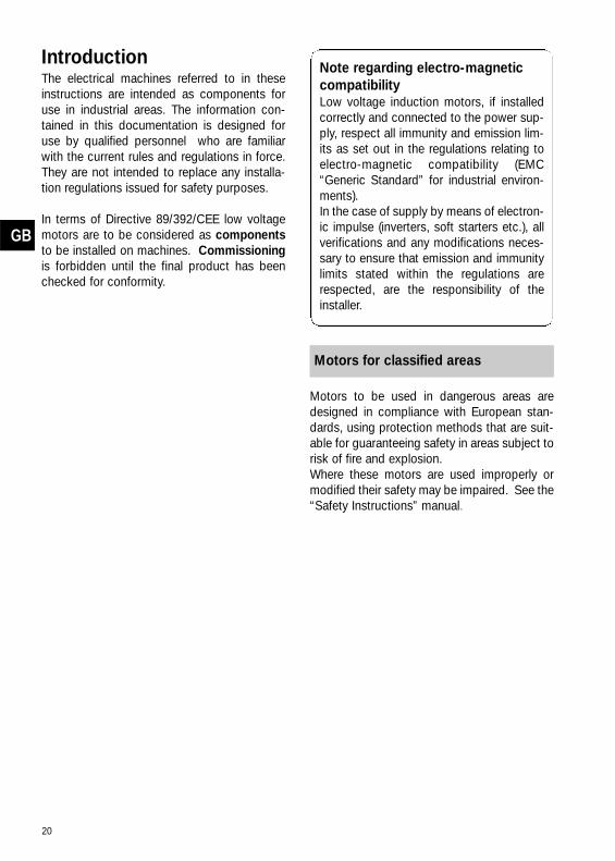
Note regarding electro-magneticcompatibilityLow voltage induction motors, if installedcorrectly and connected to the power sup-ply, respect all immunity and emission lim-its as set out in the regulations relating toelectro-magnetic compatibility (EMC“Generic Standard” for industrial environ-ments). In the case of supply by means of electron-ic impulse (inverters, soft starters etc.), allverifications and any modifications neces-sary to ensure that emission and immunitylimits stated within the regulations arerespected, are the responsibility of theinstaller.
Motors to be used in dangerous areas aredesigned in compliance with European stan-dards, using protection methods that are suit-able for guaranteeing safety in areas subject torisk of fire and explosion. Where these motors are used improperly ormodified their safety may be impaired. See the“Safety Instructions” manual.
Motors for classified areas

GB
21
1. General safety warnings
Rotating electric machines are dangerous. Consequently:- improper use- removal of protection and disconnection of pro-
tection devices- lack of inspection and maintenance can cause
serious harm.The personnel must be informed of any dangercaused by contact with:
- live parts
- rotating parts
- hot surfaces. In normal working conditionsthe motor exceeds 50 °C.
The safety manager must ensure and guarantee that:- the machine is moved, installed, put in service
inspected, maintained and repaired only by qual-ified personnel, who should have:
- specific technical training and experience- knowledge of technical standards and applicable
laws- knowledge of general safety regulations as well as
national, local and installation regulations- ability to recognize and avoid all possible dangers.Work on the electric machine should be carriedout upon authorization of the safety managerafter having ensured that:a) the motor has been disconnected from the power
supply and that no parts of the motor includingauxiliary parts are live
b) discharge of the capacitor has been done forsingle phase motors
c) the motor is completely stopped and there is nodanger of accidental restarting
d) the right precautions against faulty braking opera-tions have been taken for self-braking motors
where thermal protection with automatic resetis used care must be taken to ensure automaticrestart cannot occur. Since the electric machinereferred to is intended to be used in industrial areas,additional protective measures must be takenand guaranteed by the person who is in charge ofinstallation where more stringent protectivemeasures are needed.
1.1 Danger

22
Standards and specifications
INTERNATIONAL EU I GB F D
Title IEC CENELEC CEI-EN BS NFC DIN/VDE
Electrical rotating machines/rated operationand characteristic data
IEC 60034-1 EN 60034-1 CEI-EN 60034-1(CEI 2-3)
BS 4999-1BS 4999-69
NFC 51-100NFC 51-111
VDE 0530-1
Methods for determining losses and efficiency of rotating electrical machinery
IEC 60034-2 EN 60034-2 CEI-EN 60034-2 (CEI 2-6)
BS 4999-34 NFC 51-112 VDE 0530-2
Protection types of rotating electricalmachines
IEC 60034-5 EN 60034-5 CEI-EN 60034-5 (CEI 2-16)
BS 4999-20 NFC 51-115 VDE 0530-5
Cooling methods of rotating electricalmachines
IEC 60034-6 EN 60034-6 CEI-EN 60034-6 (CEI 2-7)
BS 4999-21 IEC 34-6 DIN IEC 34-6
Construction types of rotating electricalmachines
IEC 60034-7 EN 60034-7 CEI-EN 60034-7(CEI 2-14)
BS 4999-22 NFC 51-117 DIN IEC 34-7
Terminal markings and direction of rotationfor electrical machines
IEC 60034-8 EN 60034-8 CEI 2-8 BS 4999-3 NFC 51-118 VDE 0530-8
Noise emission, limit values IEC 60034-9 EN 60034-9 CEI-EN 60034-9(CEI 2-24)
BS 4999-51 NFC 51-119 VDE 0530-9
Start-up behaviour of squirrel-cage motorsat 50 Hz up to 660V
IEC 60034-12 EN 60034-12 CEI-EN 60034-12(CEI 2-15)
BS 4999-112 IEC 34-12 VDE 0530 12
Vibration severity of rotating electricalmachines
IEC 60034-14 EN 60034-14 CEI-EN 60034-14(CEI 2-23)
BS 4999-50 NFC 51-111 DIN ISO 2373
Fixing dimensions and outputs for IM B3 IEC 60072 EN 50347 IEC 60072 BS 4999-10 NFC 51-104/110 DIN 42673
Fixing dimensions and outputs for IM B5, IM B14
IEC 60072 EN 50347 IEC 60072 BS 4999-10 NFC 51-104/110 DIN 42677
Cylindrical shaft ends for electrical machines
IEC 60072 EN 50347 IEC 60072 BS 4999-10 NFC 51-111 DIN 748-3
Electrical equipment for hazardous areasGeneral provisions
IEC 60079-0 EN 60079-0 (CEI 31-8) BS 5501-1 NFC 23-514 VDE 0171-1
Electrical equipment for hazardous areasFlame-proof enclosure “d”
IEC 60079-1 EN 60079-1 (CEI 31-1) BS 5501-5 NFC 23-518 VDE 0171-5
Electrical equipment for hazardous areasIncreased safety “e”
IEC 60079-7 EN 60079-7 (CEI 31-7) BS 5501-6 NFC 23-519 VDE 0171-6
Checking and maintenance of electrical systems in places in danger of explosiondue to the presence of gas
IEC 60079-17 EN 60079-17 CEI EN 60079-17 ---- ---- ----
Electrical systems in places in danger ofexplosion due to the presence of gas
IEC 60079-14 EN 60079-14 CEI EN 60079-14 ---- ---- ----
Classification of dangerous places due ofthe presence of gas
IEC 60079-10 EN 60079-10 CEI EN 60079-10 ---- ---- ----
Checking and maintenance of electrical systems in places in danger of explosiondue to the presence of dust
IEC 61241-17 EN 61241-17 CEI EN 61241-17 ---- ---- ----
Electrical systems in places in danger ofexplosion due to the presence of dust
IEC 61241-14 EN 61241-14 CEI EN 61241-14 ---- ---- ----
Classification of dangerous places due ofthe presence of dust
IEC 61241-10 EN 61241-10 CEI EN 61241-10 ---- ---- ----

GB
23
2. Storage and installation
The motors are shipped ready for installation. Uponreceipt remove packaging and turn the shaft tocheck the motor has not been damaged, also checkall physical aspects of the machine for damage. Inthe case where the machine is damaged an immedi-ate notification must be given in writing by the store-man and the representative of the carrier to Cempwithin 3 days.
2.2.1 Storage conditionsIf the motors are not used immediately, they shouldbe stored in a clean, dry temperate environment freeof vibrations and protected from the weather. (Ifstored below -15 °C, and before starting, the motortemperature must be restored to the permissibleworking temperature range (i.e. -15 °C ➝ 40 °C). Inthis case, it is necessary to specify these partic-ular storage conditions during the ordering stageso that proper precautions can be taken duringbuilding and packaging.
2.2.2 Checking bearingsWhen the motors are stored properly, bearingsnedd, no maintenance. However, it is a good idea toturn the shaft by hand every three months. After stor-age of over one year motors with unshielded bear-ings (usually such motors have a lubricator and beara lubrication plate), it is advisable to check the con-dition of the lubrication and motor components.
2.2.3 Checking insulation Before installation check the motor windings usingthe appropriate instruments to ensure the conditionof the insulation between phases and betweenphase and earth are of the corrects resistance val-ues.
Do not touch the terminals during and imme-diately after measuring as they are live.
If the insulation resistance value is less than 10megaohm, or after storage in a damp environment,the motors must be dried in an oven for about 8hours by gradually bringing the temperature up to100 °C. To ensure that the dampness has beencompletely expelled, the motors must be disman-tled.
2.2.4 Operating precautionsAll operations listed above must be carried out byqualified personnel. In case of flame-proof motors itis necessary:- to be very careful that the flame-proof character-
istics are not altered- to have the procedure described in point 2.2.2
carried out by authorized repair shops- to be aware that dismantling or opening of the
motor during the warranty period without authori-zation of Cemp may invalidate the warranty.
Work on the electric machine must becarried out when the machine has stopped andbeen disconnected from the power supply (includ-ing auxiliary parts, such as anticondensationheaters).
2.3.1 LiftingBefore using the lifting rings make sure they havebeen tightened.
The lifting rings are big enough to bear theweight of a single motor, therefore they must notbe used to lift the equipment connected to themotor.
In environments where the temperature is below -20°C, these lifting rings should be used with caution asthey could break at low temperatures and causedamage.
2.3.2 Assembly of connecting device Fitting pulley, coupling or gear to the motor shaftmust be carried out with care to ensure no damageis caused to the bearing. Remove the protectivepaint finish from the shaft and smear with oil then fitthe device, heating before fitting if possible to ensurean easy fit.
Any component that is assembled on the motor shaftmust be accurately balanced.
The motor is normally balanced using a half key andthe letter H is punched on the shaft.
Fitments not balanced properly can cause anom-alous vibrations during operation that jeopodises theproper working of the motor and drastically reducesits life.
2.3 Installation 2.2 Storage procedure
2.1 Control

GB
24
2.3.3 Direct connectionUse couplings that have been made and balancedperfectly align the motor shaft and the operatingmachine precisely. Inaccurate alignment maycause vibrations and damage to the bearings orbreakage of the shaft end.
2.3.4 Connection by means of pulley Check that alignment with the pulley of the operatingmachine has been carried out perfectly. The tensionof the belts must be enough to avoid slipping.Excessive tension of the belts causes harmful radialloads on the motor shaft and bearings, reducingtheir life.
It is advisable to assemble the motor on belt-ten-sioning slides in order to regulate tension of the beltsexactly.
Connection with belts must be such as to avoidaccumulation of static charges in the moving beltswhich could cause sparks.
2.3.5 Connection to power supplyUse cables with sufficient section to bear the maxi-mum current absorbed by the motor, avoiding over-heating and/or drops in voltage. Connect the cablesto terminals by following the instructions on the plateor on the diagram included in the terminal box.Check that terminal nuts are tightened.
Connections to the terminals must be madein order to guarantee safe distances between liveuncovered parts.
Earthing is through the screw located inside theterminal box. Flame-proof motors are provided witha second earth stud located on the motor casingoutside the terminal box. Earths must be of suffi-cient size and installed according to relevantstandards. The area of contact of connections mustbe cleaned and protected against corrosion.
When the cable inlet is made by means of a cablegland, it must be chosen properly in relation to thetype of plant and type of cable used. The cable glandmust be tightened so that the retaining rings createthe pressure necessary to:
a) prevent transmission of mechanical stress to themotor terminals
b) ensure the mechanical (IP degree) protection ofthe terminal box.
For flame-proof motors the cable inlet must bemade by complying with the regulations in point 13of the standard IEC 60079-1. Apertures not usedmust be closed in accordance with specifications inpoint 13 of the same standard. When reassembling the terminal cover, make surethat if there is a seal, and it is in the right place.Flame-proof motors do not have a seal so beforereassembling the terminal box it is necessary toreplace the layer of grease. The terminal box covermust be tightened to ensure it is properly sealed.
2.3.6 Connection of auxiliary parts (Table B)a) thermal protection
Check which type of protection is installed beforemaking connections. If thermistors (PTC) areused, it is necessary to utilize a suitable relay. Donot apply a tension over 6V during the thermistorcontinuity test.
b) anti-condensation heatersIf the motor is fitted with anti-condensationheaters, their power supply must be separatedfrom that of the motor, using the terminals housedin the terminal box.
WARNING: the supply of the heater is alwaysmonophase and the voltage is different from that ofthe motor. Check that it corresponds to the one indi-cated on the plate.
c) auxiliary ventilation Connect the supply of the auxiliary ventilationmotor separately from that of the main motor.
WARNING: use a device that allows startingand operation of the main motor only when the aux-iliary fan is working.
d) all the above-mentioned operations must be car-ried out by following the instructions shown on theconnection diagram provided with the motor.

GB
25
2.3.7 Fixing to the baseThe bolts fixing the motor to the base must be fittedwith washers that they ensure adequate load distri-bution.
■

GB
26
3. Putting into operation
It is the responsibility of the installer to esta-blish the motor's fitness to be used in a certainplant, after analysing the characteristics of dangerexisting in the installation area with respect to cur-rent provisions of the law and to those issued forsafety purposes.
Before starting the motor it is important to checkthat:a) installation has been carried out properly b) the bearings have not been damaged during
installationc) the motor base is sturdy enough and the founda-
tion bolts have been tightenedd) the design data corresponds to those given on the
plate and in the technical documentation
The electric motor is a component made tobe mechanically connected to another machine (sin-gle or part of a plant). Consequently, it is the task ofthe person responsible for the installation to gua-rantee that during operation there is an adequatedegree of protection for people or things againstthe danger of accidental contact with movingparts.
Make sure that the motor is suited for use in the wor-king conditions foreseen and check the following:
3.2.1 Environmental conditionsa) ambient temperature: standard closed motors
can operate between -15 °C and + 40 °C.Standard motors for classified areas (Ex d, Exde, Ex e, Ex n) can operate between -20 °C and+ 40 °C.
b) altitude:normal motors have been designed to work bet-ween 0 and 1.000 m above sea level
c) protection against the presence of harmful agentslike: sand, corrosive substances, dust and/orfibre, water, mechanical stress and vibrations
d) mechanical protection:installation inside or outside considering theharmful effects of the weather, the combinedeffect of temperature and humidity and the forma-tion of condensation
e) adequate space around the motor particularly onthe fan side to allow proper ventilation
f) motors mounted in the vertical, shaft down requirea protective cowl over the fan inlet
g) any danger of explosion or fire.
3.2.2 Working conditionsa) The motor must only be assembled and operated
in the construction form indicated on the motorplate.
b) operation type:the motors are normally for S1 duty continuousoperation
c) load type:carefully evaluate machines with high moments ofinertia and the relative starting times
d) for motors intended for operation in hazardousareas (Ex d or Ex e) the motor type and tempera-ture classification must comply with the area rat-ingWhen there is an “X” on the plate near the cer-tificate number, it is necessary to check on thecertificate which additional conditions arerequired for proper working.
e) for self-braking motors see the special applica-tions envisaged in the relative catalogue.
3.2.3 Electrical characteristics a) voltage and frequency should correspond to
those on the plateb) motor power should be adequate as required by
the load c) power supply protection against overloads and/or
short circuits should be adequate for the nominalcurrent and starting current
d) for connection to control circuits follow the con-nection diagram supplied with motor (Table A)
Abnormal working conditions must alwaysbe defined when placing order to ensure that thesite conditions are not prejudicial to the proper oper-ation of the machine
3.2.4 Other checks before commissioning• Check that the motor rotates in the correct direc-
tion, and that when the inverter is activated thespeed limit is not exceeded.
• Check that the motor is protected as prescribed inthe standards.
• Where using a star/delta starter, to avoid the riskof overloading make sure that the switch overfrom star to delta only takes place when the start-ing current has been adequately reduced.
• Check that any auxiliary accessories are working.
3.2 Control of Design Data
3.1 Initial Controls

GB
27
3.3.1 Earthing connectionBefore starting the motor ensure that the incomingsupply cables are connected correctly
3.3.2 Motors with auxiliary ventilationFor motors with forced ventilation by means of exter-nal ventilation make sure that the motor starter isinterlocked with the, contactor of the external venti-lator to ensure the fan is operational.
3.3.3 Start upWhen all previous checks have been made satisfac-torily, the motor may be started. Unless otherwisestated all motors can be direct on line started. If youintend to start the motor by means of staticstarters, rheostats or the star-delta system, theymust be chosen and set property to avoid incor-rect functioning of the motor.
3.4.1 Working featuresOnce the motor has started it is necessary to checkthat during operations the working conditions remainwithin the limits envisaged, and that the followingdoes not occur:a) overloadb) dangerous rise in environmental temperature c) excessive drop in voltage
Every time there is a change in the working con-ditions, it is necessary to check that the completefitness of the motor has been maintained for thenew operating conditions.For example:- variation in working cycle- the function of the motor has altered - moving of the motor to a different environment
(from outside to inside)- moving of the motor from a low temperature envi-
ronment to one with a higher temperature.
3.4.2 Restarting after long restBefore starting the motor after a long resting period,repeat the controls described in section 2.2.2 and2.2.3.Where supplied, heater must not be energisedwhen the motor is running.
3.4.3 Anomalous conditionsThe motor must be used solely for applications itwas designed for and must be utilized and controlledcomplying with the precautionary standards.
If the machine shows anomalous workingcharacteristics (greater absorption, increase intemperature, noisiness, vibrations), inform thepersonnel in charge of maintenance immediately.
3.4.4 Protection against overloadingIn terms of the IEC 60079-14 standard all motors areto be protected using a suitable switch, such as onewith a delayed trip that is triggered by the current, aswell as protection in case of a phase going down.The protective device is to be set at the nominal cur-rent shown on the plate. This device must be cho-sen so that the motor is protected thermally shouldthe rotor jam.
The windings connected in delta must be protectedin such a way that the switches or relays are con-nected in series with the winding phase. Switchesare to be chosen and set taking the nominal phasecurrent, that is, 0,58 times the motor’s nominal cur-rent, as the base value.
3.4 Conditions of Use
3.3 Starting
■
GB
28
4. MaintenanceAny operation on the motor must be car-
ried out with the machine stopped and disconnectedfrom the power supply (including auxiliary circuits,especially the anticondensation heaters).Maintenance of the original characteristics ofelectric machines over time must be ensured bya schedule of inspection, maintenance and set-ting up managed by qualified technicians. Thetype and frequency of maintenance depends onenvironmental and working conditions. As a rule, itis recommended that the first inspection is madeafter about 500 hours of operations (or, within 1year), while subsequent inspections should followthe schedules established for lubrication and gene-ral inspection.
4.1.1 Normal workingCheck that the motor works normally without ano-malous noise or vibrations. If it does not, locate thecause of the anomaly.
4.1.2 Cleaning the surfaceMake sure that the ventilation is not obstructed.Clean the motor by removing any dust or fibre depo-sits from the fins and from the fan cover.
4.1.3 Checking the supply and earthing cableCheck that the supply cable does not show signs ofwear and that the connections are tight. Make surethat the earth and supply cables are not damaged.
4.1.4 Transmission elementsCheck that the transmission elements are in perfectcondition and that the screws and nuts are tight.
4.1.5 Protection against waterWhen the motor is installed in a very damp environ-ment or is subject to drips of water, check regularlythat the seal and retaining rings and any protectivedevices work efficiently. Ensure that there are noinfiltrations inside the casing or terminal box.
4.1.6 Drainage devices The motors furnished with drainage devices shouldbe checked and cleaned regularly so that such devi-ces continue to work properly.
4.1.7 Thermal protectionMake sure that thermal protections have not cut outand have been set properly.
The right selection and setting of thermal pro-tections for Ex e motors is essential to guarantee thetemperature class and safety against the danger ofexplosion.
4.1.8 Unauthorized modifications Check that no modifications have been madethat alter the electric and mechanical operationof the motor.
4.1.9 Painting When the motor is installed in an environment wherethere are corrosive agents it is recommended topaint the motor itself to protect the outer surfacesfrom corrosion if necessary.
4.1.10 Reconditioning operationsEvery irregularity or fault found during inspectionmust be fixed immediately.
4.2.1 Permanently lubricated bearingsMotors with shielded or sealed bearings (type ZZ or2RS) do not require lubrication. Therefore, if usedproperly, they do not require maintenance.
4.2.2 Bearings with lubricatorMotors with unshielded bearings are furnished withlubricators. The interval time between lubricationsdepends on the type of grease, environmental tem-perature, (any excessive working temperature) andtype of operation the motor carries out. The table Cshows the intervals foreseen for 70 °C as a workingtemperature of the bearings in normal operatingconditions. It is recommended to use a good qualitylithium based grease with great penetration capacityand high dropping point like Athesia 3 by IP, Beacon3 by Esso or Avana 3 by Shell. If the velocity is dif-ferent from the one given in the table, the intervalsmust be modified in inverse proportion.
Eg. bearing 6314 at 1.800 RPM
1 = 1500 x 3550 h = 2950 h1800
Regardless of working hours, the grease must berenewed after 1 or 2 years or during a completeoverhaul. When the motor is furnished with a lubri-cation plate, refer to the dates shown on it.
4.2 Lubrication
4.1 Inspection
GB
29
All operations must be carried out bearing inmind health and safety regulations.
4.3.1 Consulting the catalogueBefore working on the motor it is advisable to con-sult the relevant catalogue and have all the toolsready.
4.3.2 Disconnection from power supplyBefore proceeding with dismantling, the motor mustbe disconnected from the power supply. Make surethat the power is off disconnect supply cables andauxiliary cables when there are any.
4.3.3 Placing on workstandIn order to work on the motor satisfactorily it shouldbe removed from its mounting and placed on a workbench.
4.3.4 Dismantling procedureTake off the fan cover by removing the fixing screws.Using an extractor remove the cooling fan. Removethe end shields and withdraw the rotor being carefulnot to damage the windings. Precautions must betaken with flameproof motors so that the spigotson the frame and the end shields are not dama-ged. When the motor is dismantling and before it isreassembled it is necessary to protect the variouscomponents (particularly the bearings and windings)to avoid damage caused by dust or knocks.
4.3.5 Additions for self-braking motorsFor dismantling of self-braking motors follow theinstructions shown in the relative catalogue.
4.4.1 Dismantling of bearingsa) Bearings interference fit to shaft: remove the bear-
ings with the aid of a suitable extractor.b) Bearings interference fit to end shield: heat end
shield to a temperature between 140 and 160 °Cand then remove the bearings with the aid of asuitable extractor.
In both cases, check that the respective housingshave not been damaged. Then proceed with fittingthe new bearings, these should be identical to thosebeing replaced.
4.4.2 Fitting new bearingsa) Bearings interference fit to shaft: heat the bear-
ings to 120-130 °C and push them quickly ontothe shafts. If required, use a mallet and a brasssleeve, this must rest on the inner race of thebearing. Alternatively, if it is not possible to heatthe bearings, we recommend using a press and asuitable sleeve which must rest on the inner raceof the bearing.
b) Bearings interference fit to end shield: heat theend shield to a maximum temperature of 140 °C,then position the bearing in its housing, pushing ituntil it rests against the snap ring (Seeger).
4.4.3 Checking the bearings a) Bearings interference fit to shaft: after assembly
has been completed the inner ring of the bearingmust rest against the relevant shaft shoulder.
b) Bearings interference fit to end shield: afterassembly has been completed the inner ring ofthe bearing must rest against the snap ring(Seeger).
4.4.4 Reassembling the motorBefore reassembling, clean the internal parts of themotor carefully and check that the components havenot been damaged. Renew the layer of grease whereneeded on the abutting spigots and proceed withthe reassembling.
4.5.1 Spare parts When needed, all motor components should bereplaced by original spare parts. To request spareparts use the nomenclature shown in the cataloguesand always give:- motor type
- serial number
- year built
4.5.2 Personnel qualification - Authorized repairshopsOverhauls and repairs must be carried out bytrained personnel who guarantee restoration ofthe motor to its original conditions, we recom-mend that you contact an authorised repairagent. For further information please contact oursales department.
4.5 Overhauls and Repairs
4.4 Replacing the bearings
4.3 Dismantling and Reassembling the Motor
■

GB
30
5. TroubleshootingProblem Possible Cause Solution
The motor does not start Fuses damaged due to overloading Replace the fuses with similar onesof the correct size.
Opening of the overload switch Check and reset the switches.
Insufficient power available Check that the power required is asshown on the motor’s plate.
Connections incorrect Check that the connections are as shown in the motor’s connectiondiagram.
Mechanical fault Check that the motor and the machine to which it is coupled turn freely. Check the bearings and lubricant.
Short circuit on the stator The motor must be rewound.
Defective rotor Check whether the bars and the rings are broken, if necessary replace the rotor.
One phase is down Check the connection cables.
Incorrect application Check the sizing with the manufacturer.
Overload Reduce the load.
Voltage too low Make sure that the motor is poweredat the voltage shown on the plate.
The motor does not reach itsnominal speed or the acceleration times are toolong and/or absorption excessive
Voltage drop on the line Check the connections. Check that the cables are of the correct size.
Excessive inertia Check the size of the motor.
Defective rotor Check the state of the rotor cage.Replace the rotor if necessary.

GB
31
Problem Possible Cause Solution
The motor overheats whenworking under load
Overloaded Reduce the load.
Cooling fins and/or fan cover blocked by dirt
Clear the ventilation slots to ensurea continuous flow of air over themotor.
One phase on the motor may bedown
Check that all the cables are connected tightly and correctly.
One phase on the winding is earthed Check the winding and remove thefault.
Phase voltages asymmetrical Check the power supply and motor-voltages and rebalance the loads.
Duty too great Use the motor for the service indicated on the plate.
Incorrect rotation Incorrect phase sequence Invert two phases.
Functioning of the protectivedevice
The motor may have one phasedown
Check the power supply.
Wrong connection Follow the wiring diagram for theconnections and the performancedata shown on the plate.
Overloaded Compare against the data on theplate and reduce the load if necessary.
Abnormal vibrations Motor not aligned Align the motor with the machine itcontrols.
Base weak Reinforce the base. Check the bolts.
Coupling or pulley not balanced Balance the device.
Coupled machine unbalanced Balance the coupled machine.
Defective bearings Replace the bearings.
Motor balanced differently fromthe coupling (half key – full key)
Balance the coupling using the halfkey.
Three-phase motor working with 1phase down
Check the phases and reinstate thethree-phase system.
Excessive play on the bearings Either:- replace the bearings- replace the shield - add a shim to the bearing seating.
Irregular noise Fan touching the fan cover Eliminate contact.
Defective bearings Replace the bearings.

GB
32■
Problem Possible Cause Solution
Bearings overheating Motor fitted incorrectly Check that the motor is adequate for the type of fitting.
Belts over-tensioned Reduce the belt tension.
Pulleys too far from the shaft shoulder
Move the pulley nearer to the shoulder on the motor shaft.
Pulley diameter too small Use a bigger pulley.
Alignment incorrect Correct the alignment of the motorand the machine coupled to it.
Insufficient grease Keep the correct amount of lubricant in the bearings.
Lubricant ineffective or contaminated
Remove the old grease, wash contaminated bearings carefully andgrease with new lubricant.
Excessive lubricant Reduce the amount of lubricant.The bearing must not be more thanhalf full.
Bearing overloaded Check the alignment and any radialand/or axial thrust.
Bearing balls or race damaged Replace the bearing.

GB
33
Connecting diagrams - Table A
Connection for single speed motors:
Y-ConnectionU2W2 V2
W1V1U1
L1 L2 L3
U1
W1 V1
Connection-Δ
V1W1
U1
U1
W2 U2 V2
V1 W1
L1 L2 L3
Number of pole: 2, 4, 6, 8 .... - Synchronous speed at 50 Hz: 3000, 1500, 1000, 750 ....
Two separate windings for two speed motors:
Number of pole: 2/6, 2/8, 4/6, 6/8 .... - Synchronous speed at 50 Hz: 3000/1000, 3000/750, 1500/1000, 1000/750 ....
Low Speed
U1
W2 U2 V2
L1 L2 L3
V1 W1
U1
W1 V1
High Speed
U1
W2 U2 V2
L1 L2 L3
V1 W1
W2
V2 U2
Dahlander system for two speed motors, constant torque:
High Speed
U2
W2
V2
W1
V1
U1 V1 W1U1
W2 U2 V2
L1 L2 L3
Low Speed
V1W1
U1
U2
V2 W2
U1
W2 U2 V2
L1 L2 L3
V1 W1
Number of pole: 2/4, 4/8 - Synchronous speed at 50 Hz: 3000/1500, 1500/750
Dahlander system for two speed motors, quadratic torque:
High Speed
V1 W1U1
W2 U2 V2
L1 L2 L3
W2
V2 U2
U1W1V1
Low Speed U1
W1 V1
U2V2
W2
U1
W2 U2 V2
L1 L2 L3
V1 W1
Number of pole: 2/4, 4/8 - Synchronous speed at 50 Hz: 3000/1500, 1500/750
Connection for single-phase and special motors.
For single-phase motors and motors with special connections, refer to the diagrams provided with the motor.

GB
34
Lubrication intervals in hours for unshielded bearings - Table C
Use the data shown on the motor’s plate.
Bearings Amount of Grease 3000 1500 1000 750“in Grammes” RPM RPM RPM RPM
6 205 4 4500 9500 10000 100006 206 5 4000 8500 10000 100006 306 6.5 3750 8000 10000 100006 208 10 2800 6000 9000 100006 308 10 2800 6000 9000 100006 309 12.5 2350 5600 8500 10000
NU 309 12.5 1180 2800 4250 60006 310/11 17 1800 4500 7500 10000
NU 311 17 950 2350 3750 50006 312 21 1600 4000 7100 9500
NU 312 21 800 2250 3550 47506 313 24 1400 3750 6700 9000
NU 313 24 700 2000 3350 45006 314 26 1250 3550 6300 8500
NU 314 26 600 1800 3150 42506316/7316 33 900 3150 5600 8000
3 316 58 - 3150 5600 8000NU 316 33 450 1600 2800 4000
3318/7318 41 - 2650 5000 71003 318 70 - 2650 5000 7100
NU 318 41 - 1400 2650 35506320/7320 51 - 2360 4500 6300
3 320 90 - 2360 4500 6300NU 320 51 - 1180 2360 3350
Additional terminals marking (IEC60034-8) - Table B
Marking No. terminals Additional terminal for:TP1 - TP2 (warning)TP3 - TP4 (switch off)
22
Thermistor PTC (*)
R1 - R2 - R3 (I sensor)R4 - R5 - R6 (II sensor)R7 - R8 - R9 (III sensor)
333
Thermistor PT 100 with 3 wires
R11 - R12 - R13 (DE)R21 - R22 - R23 (NDE)
33
Thermistor PT 100 on bearing
TB1 - TB2 (warning)TB3 - TB4 (switch off)
22
Normally closed bi-metallic switch (**)
TB8 - TB9 (switch off) 2 Normally closed brake bi-metallic switch (**)TM1 - TM2 (warning)TM3 - TM4 (switch off)
22
Normally open bi-metallic switch (**)
HE1- HE2 2 Space heatersU1 - U2 2 Single phase forced ventilationU - V - W 2 Three phase forced ventilationcolours according manufacturer diagram 9 EncoderCA1 - CA2 2 CapacitorPE 1 Earth cable(*) U rated = 6V - max 30V - (**) U rated = 250V

Programmadi vendita
Sales programme Programme Lieferprogramm Programade venta
MotoriantideflagrantiEx d - Ex de• gruppo I-IIA-IIB-IIC• categoria
M2, 2G, 2D, 2GD• classe
T3-T4-T5-T6• trifasi,
monofasi• con freno
FlameproofmotorsEx d - Ex de• group I-IIA-IIB-IIC• category
M2, 2G, 2D, 2GD• class
T3-T4-T5-T6• threephase,
singlephase• with brake
MoteursantidéflagrantsEx d - Ex de• groupe I-IIA-IIB-IIC• catégorie
M2, 2G, 2D, 2GD• classes de température
T3-T4-T5-T6• triphasés,
monophasés• avec frein
ExplosionsgeschützteMotorenEx d - Ex de• Gruppe I-IIA-IIB-IIC• Kategorie
M2, 2G, 2D, 2GD• Klasse
T3-T4-T5-T6• Dreiphasen- und
Einphasen-Ausführung• mit Bremse
Motores antideflagrantesEx d - Ex de • grupo I-IIA-IIB-IIC• categoría
M2, 2G, 2D, 2GD• classe
T3-T4-T5-T6• trifásicos,
monofásicos• con freno
Motori asicurezza aumentataEx e• gruppo II• categoria 2G• classe
T1-T2-T3
Increased safety motorsEx e• group II• category 2G• class
T1-T2-T3
Moteurs à sécuritéaugmentéeEx e• groupe II• catégorie 2G• classes de température
T1-T2-T3
Motoren in Schutzart“erhöhte Sicherheit” Ex e• Gruppe II• Kategorie 2G• Klasse
T1-T2-T3
Motores deseguridad aumentadaEx e• grupo II• categoría 2G• clase
T1-T2-T3
Motori non sparkingEx nA• gruppo II• categoria 3G, 3GD
Non sparking motorsEx nA• group II• category 3G, 3GD
Moteurs anti-étincelleEx nA (non sparking)• groupe II • catégorie 3G, 3GD
Funkenfreie MotorenEx nA• Gruppe II• Kategorie 3G, 3GD
Motores no sparking Ex nA• grupo II• categoría 3G, 3GD
Motori chiusicon ventilazioneesterna IEC• trifasi,
monofasi• categoria 3D
Totally enclosedfan cooled IEC motors• threephase,
singlephase• category 3D
Moteurs IP 55 IECavec ventilationextérieure• triphasés,
monophasés• catégorie 3D
Vollgekapselteluftgekühlte Motorennach IEC• Dreiphasen- und
Einphasen-Ausführung• Kategorie 3D
Motores cerrados con ventilaciónexterior IP 55 IEC• trifásicos,
monofásicos • categoría 3D
Elettropompecentrifugheantideflagrantiper macchineda stampaEx d - Ex de
Centrifugal flameproofelectric pumps for printingmachinesEx d - Ex de
Electropompescentrifugesantidéflagrantes pour machinesd'imprimerieEx d - Ex de
ExplosionsgeschützteZentrifugal-Elektropumpenfür DruckmaschinenEx d - Ex de
Electrobombascentrífugas paramáquinas deimpresiónEx d - Ex de
Elettropompecentrifughe permacchine utensili
Centrifugal electric pumps formachine tools
Electropompescentrifuges pourmachines-outils
Elektropumpenfür Werkzeugmaschinen
Electrobombas centrífugas paramáquinas herramientas
Nel redigere questa documen-tazione è stata posta ognicura al fine di assicurare lacorrettezza delle informazio-ni contenute.
Tuttavia, anche in conse-guenza della politica di con-tinuo sviluppo e migliora-mento della qualità del pro-dotto perseguita da Cemp, lasocietà si riserva il diritto ela facoltà di apportare modi-fiche di qualsiasi genere, inqualsiasi momento e senzapreavviso, sia a questo docu-mento sia ai propri prodotti.
Le descrizioni e le caratteri-stiche tecniche della presen-te pubblicazione non sonoquindi impegnative e i datiriportati non costituiscono,in nessun caso, impegnocontrattuale.
Every care has been taken toensure the accuracy of theinformation contained in thispublication.
Due to Cemp’s policy of con-tinuous development andimprovement, the companyreserves the right to supplyproducts which may differslightly from those illustra-ted and described in thispublication.
Descriptions and technicalfeatures listed in this bro-chure may not be consideredas binding. Under no circum-stances should data in thispublication be considered asa contractual obligation.
Dans la préparation de cettedocumentation nous avonspris le soin d’y intégrer lesinformations les plus exactespossibles.
Néanmoins, compte tenu denotre politique de dévelop-pement et d’améliorationcontinue des produits, laSociété Cemp se réserve ledroit et la faculté d’apportertoute modification sur ladocumentation et sur les pro-duits, à tout moment et sanspréavis.
Les descriptifs et les caracté-ristiques techniques conte-nus dans ce catalogue n’en-gagent pas la Société. Par conséquent, ces donnéesne constituent en aucun casun engagement contractuel.
Die Ausführungen und tech-nischen Eigenschaften, die indieser Broschüre angegebensind, dürfen nicht als ver-bindlich angesehen werden.
In keinem Fall können jedochdie in diesem Dokument auf-geführten technischen Datenals rechtlich verbindlichangesehen werden.
Cemp behält sich das Rechtvor, ohne Mitteilung, jeglicheAbweichungen und Änderun-gen jederzeit vorzunehmen,sowohl in diesem Dokumentals auch bei den Produkten,die hier beschrieben sind.
La presente documentación seha redactado de manera muyatenta para poder asegurarque las informaciones quecontiene son correctas.
No obstante, como consecuen-cia de la política de continuodesarrollo y mejora de la cali-dad del producto que Cemppone en práctica, la sociedadse reserva el derecho y lafacultad de modificar en loque fuera necesario, en cual-quier momento y sin que paraello medie preaviso alguno,tanto este documento comosus productos.
Por lo tanto, las descripcionesy las características técnicasindicadas en el presente docu-mento no son vinculantes, ylos datos que contiene noconstituyen en ningún caso,vínculo contractual.

Cemp SpAVia Piemonte, 16 I 20030 SENAGO (MI) Tel. +39 02 99 01 08 04Fax +39 02 99 89 [email protected]
Cemp France SA
6 et 8, avenue Victor Hugo F 27320 NONANCOURTTél. +33 (0)2 32 58 03 81Fax +33 (0)2 32 32 12 98 [email protected]
Cemp International GmbHAm Mollnhof 2D 94036 PASSAUTel. +49 (0)851 96 62 320Fax +49 (0)851 96 62 32 [email protected]
O v e r a l l s a l e s n e t w o r k a t w w w. c e m p . e u