Embed Size (px)
Citation preview
GR
© KROHNE 11/2003 7.30855.34.00
Ultrasonic Flowmeters
ALTOSONIC VReference Guide
Modbus ManualProtocol description & set-up
Applicable for Software version 0300
Variable area flowmeters
Vortex flowmeters
Flow controllers
Electromagnetic flowmeters
Ultrasonic flowmeters
Mass flowmeters
Level measuring instruments
Communications technology
Engineering systems & solutions
Switches, counters, displays and recorders
Heat metering
Pressure and temperature

ALTOSONIC V Modbus Manual page 2 of 51
(ALTOSONIC V version 3.00.00 and higher) TABLE OF CONTENTS
1 INTRODUCTION........................................................................................................................... 4
2 SERIAL TRANSMISSION FORMAT............................................................................................ 5 2.1 ASCII-MODE ................................................................................................................................... 5 2.2 RTU-MODE ..................................................................................................................................... 5
3 MODBUS MESSAGE FRAMING ................................................................................................. 6 3.1 THE ADDRESS FIELD........................................................................................................................ 6 3.2 THE FUNCTION FIELD....................................................................................................................... 6 3.3 THE DATA FIELD.............................................................................................................................. 7 3.4 THE ERROR CHECKING FIELD .......................................................................................................... 7 3.5 OTHER ERROR CHECKING METHODS................................................................................................ 7
4 PHYSICAL COMMUNICATION LAYER ...................................................................................... 8 4.1 WHEN USING RS232 TO RS485 CONVERTERS ................................................................................. 8 4.2 WHEN USING SERIAL I/O CARDS WITH RS485 DRIVERS...................................................................... 8
5 SUPPORTED FUNCTIONS.......................................................................................................... 9 5.1 FUNCTION 01: READ COIL STATUS .............................................................................................. 9 5.2 FUNCTION 02: READ INPUT STATUS.......................................................................................... 10 5.3 FUNCTION 03: READ MULTIPLE HOLDING REGISTERS........................................................... 10 5.4 FUNCTION 04: READ INPUT REGISTERS................................................................................... 11 5.5 FUNCTION 05: WRITE SINGLE COIL ........................................................................................... 11 5.6 FUNCTION 06: WRITE SINGLE HOLDING REGISTER ................................................................ 11 5.7 FUNCTION 8: DIAGNOSTICS........................................................................................................ 12 5.8 FUNCTION 15: WRITE MULTIPLE COILS..................................................................................... 12 5.9 FUNCTION 16: WRITE MULTIPLE HOLDING REGISTERS ......................................................... 13 5.10 EXCEPTION RESPONSES............................................................................................................ 14
6 HANDLING OF LARGE DATA TYPES...................................................................................... 15 6.1 FLOATING POINT REPRESENTATION................................................................................................ 16 6.2 DOUBLE REPRESENTATION ............................................................................................................ 16 6.3 TRANSMIT SEQUENCE.................................................................................................................... 16 6.4 MAXIMUM REQUESTED POINTS ....................................................................................................... 17
7 SET-UP OF THE UFP-V MODBUS DRIVER ............................................................................. 19 7.1 DRIVER CONTENTS........................................................................................................................ 19 7.2 HARDWARE SET-UP ....................................................................................................................... 19
7.2.1 RS485/422 card: AX4285A.............................................................................................................20 7.2.2 RS485/422 card: PCL-745 S ..........................................................................................................21
7.3 SOFTWARE SET-UP ....................................................................................................................... 22 7.3.1 First set the parameters for the communication line .......................................................................22 7.3.2 Now select the parameters for the used protocol............................................................................22 7.3.3 The UFP-V as SLAVE device .........................................................................................................22 7.3.4 The UFP-V as Master .....................................................................................................................23
7.4 WHAT CAN GO WRONG?................................................................................................................. 24 7.5 HOW STATUS FLAGS ARE UPDATED................................................................................................ 24 7.6 HOW DATA IS WRITTEN TO THE FLOAT FIELD .................................................................................... 26
7.6.1 How to write in the float field to the specific application ..................................................................26 8 MODBUS MAPPING ASSIGNMENTS....................................................................................... 28
8.1 FIELD 0 (READ ONLY BOOLEAN FIELD) ............................................................................................ 28 8.2 FIELD 1 (READ/WRITE BOOLEAN FIELD) ......................................................................................... 30 8.3 FIELD 2 (READ ONLY INTEGER FIELD) ............................................................................................. 31 8.4 FIELD 3 (READ ONLY LONG INTEGER FIELD).................................................................................... 33 8.5 FIELD 4 (READ ONLY FLOAT FIELD)................................................................................................. 34

ALTOSONIC V Modbus Manual page 3 of 51
8.6 FIELD 5 (READ ONLY DOUBLE FIELD).............................................................................................. 37 8.7 FIELD 6 (READ/WRITE FLOAT FIELD) .............................................................................................. 38 8.8 EXPLANATION OF DATA AVAILABLE TO MODBUS .............................................................................. 40 8.9 THE SYSTEM MESSAGES ............................................................................................................... 44
9 APPENDICES............................................................................................................................. 46 9.1 APPENDIX A: TIME OUT VALUES...................................................................................................... 46 9.2 APPENDIX B: LRC GENERATION..................................................................................................... 47 9.3 APPENDIX C: CRC GENERATION .................................................................................................... 47 9.4 APPENDIX D: COMS0300.DAT ........................................................................................................ 50

ALTOSONIC V Modbus Manual page 4 of 51
1 INTRODUCTION This manual describes how to use the Modbus protocol with the ALTOSONIC V flow meter system. From this point in the manual the following abbreviations are used for the ALTOSONIC-V system: UFS-V: Ultrasonic Flow Sensor (primary flow meter body) UFC-V: Ultrasonic Flow Converter (5 converters) UFP-V: Ultrasonic Flow Processor Introduction to Modbus For communication with host systems the flow controller emulates a Modbus compatible controller. The Modbus protocol defines a message structure that controllers will recognise and use, regardless of the type of network over which they communicate. It describes: • the process a controller uses to request access to other devices, • how it will respond to requests from the other devices, and • how errors will be detected and reported. Controllers communicate using a master-slave principle. Only the master can initiate transactions (requests), and only the addressed device responds. In case of a broadcast request none of the slaves will respond. The Modbus request consist of: • an address, • a function code defining the requested action, • data (if necessary for the requested function), and • error check for testing the integrity of the message. The slave’s response contains: • the slave address, • data conform the request type, and • error check.
If the data integrity test fails, no response is sent back. If a request cannot be processed an exception message is returned.

ALTOSONIC V Modbus Manual page 5 of 51
2 SERIAL TRANSMISSION FORMAT The two transmission modes used are called: 1. ASCII, and 2. RTU. The user has to select the desired mode along with the serial communication parameters (baud rate, parity-type). Note that all these parameters must be the same for all controllers in the network.
2.1 ASCII-mode • Each byte of the message is sent as two ASCII characters.
This means only the ASCII characters 0-9, A-F are transmitted. • Serial communication parameters:
1 start byte, 7 data bits, even/odd/no parity, 1 stop bit if parity is used and two stop bits if no parity is used.
• Error check field: Longitudinal Redundancy Check (LRC).
The advantage of ASCII mode is that it allows for a time interval up to 1 second between characters without causing a timeout. A disadvantage of ASCII mode is the larger message length.
2.2 RTU-mode • Each byte of the message is sent as 8 bits. • Serial communication parameters:
1 start byte, 8 data bits, even/odd/no parity, 1 stop bit if parity is used, and two stop bits if no parity is used.
• Error check field: Cyclic Redundancy Check (CRC).
ALTOSONIC V Modbus Manual page 6 of 51
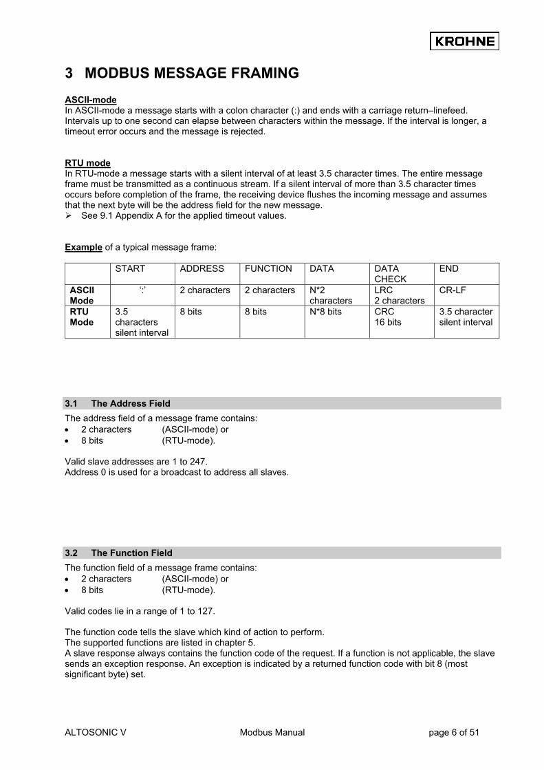
3 MODBUS MESSAGE FRAMING ASCII-mode In ASCII-mode a message starts with a colon character (:) and ends with a carriage return–linefeed. Intervals up to one second can elapse between characters within the message. If the interval is longer, a timeout error occurs and the message is rejected. RTU mode In RTU-mode a message starts with a silent interval of at least 3.5 character times. The entire message frame must be transmitted as a continuous stream. If a silent interval of more than 3.5 character times occurs before completion of the frame, the receiving device flushes the incoming message and assumes that the next byte will be the address field for the new message.
See 9.1 Appendix A for the applied timeout values. Example of a typical message frame: START
ADDRESS FUNCTION DATA
DATA CHECK
END
ASCII Mode
‘:’ 2 characters 2 characters N*2 characters
LRC 2 characters
CR-LF
RTU Mode
3.5 characters silent interval
8 bits 8 bits N*8 bits CRC 16 bits
3.5 character silent interval
3.1 The Address Field The address field of a message frame contains: • 2 characters (ASCII-mode) or • 8 bits (RTU-mode). Valid slave addresses are 1 to 247. Address 0 is used for a broadcast to address all slaves.
3.2 The Function Field The function field of a message frame contains: • 2 characters (ASCII-mode) or • 8 bits (RTU-mode). Valid codes lie in a range of 1 to 127. The function code tells the slave which kind of action to perform. The supported functions are listed in chapter 5. A slave response always contains the function code of the request. If a function is not applicable, the slave sends an exception response. An exception is indicated by a returned function code with bit 8 (most significant byte) set.

ALTOSONIC V Modbus Manual page 7 of 51
3.3 The Data Field The data field contains 8 bit values in the range of 0 to FF hexadecimal. In ASCII mode this byte is made of 2 ASCII characters. The data field of messages contains information which both master and slave use to perform an action. This includes the register address, quantity of registers, and the necessary data.
3.4 The Error Checking Field The error checking field contents depend on the transmission mode. Two kinds of error methods are used. Error check with ASCII-mode When the ASCII mode is used, the error-checking field contains two ASCII characters. The error check characters are the result of a Longitudinal Redundancy Check calculation. This is performed on the message contents with exception of the beginning colon, the carriage return and line feed characters. The LRC characters are appended to the message as the last field preceding the CR-LF characters.
See 9.2 Appendix B for more information about the Longitudinal Redundancy Check. Error check with RTU-mode When RTU mode is used, the error-checking field contains a 16-bit value implemented as two bytes. The error check value is the result of a Cyclic Redundancy Check calculation performed on the message contents. The CRC field is appended to the message as the last field.
See 9.3 Appendix C for more information about the Cyclic Redundancy Check.
3.5 Other Error Checking Methods Standard Modbus uses two kinds of error checking methods: 1. Character based check
an additional parity bit for each character (even or odd parity). 2. Message based check
an additional error check calculated over the entire message. Both character check and message check are generated in the transmitting device and applied to the message before transmission. The slave checks each character and the entire message frame during receipt. The master has a predetermined timeout interval before aborting the transaction. This interval is set long enough for any slave to respond normally. The timeout interval is set by the parameter 7.2 REQUEST_TO_RESPONSE_TIMEOUT. ASCII mode In ASCII mode the maximum time between 2 characters is one second. If a longer interval occurs, the message will be rejected and the search for a starting character (colon) is resumed. RTU mode In RTU mode the entire message frame must be transmitted as a continuous stream. If a silent interval of more than 3.5 character times occurs before completion of the frame, the receiving device flushes the incoming message and assumes that the next byte will be the address field for the new message.
ALTOSONIC V Modbus Manual page 8 of 51
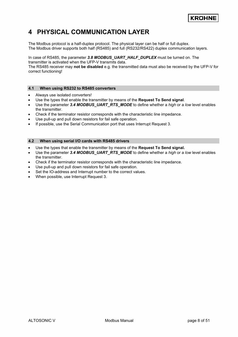
4 PHYSICAL COMMUNICATION LAYER The Modbus protocol is a half-duplex protocol. The physical layer can be half or full duplex. The Modbus driver supports both half (RS485) and full (RS232/RS422) duplex communication layers. In case of RS485, the parameter 3.8 MODBUS_UART_HALF_DUPLEX must be turned on. The transmitter is activated when the UFP-V transmits data. The RS485 receiver may not be disabled e.g. the transmitted data must also be received by the UFP-V for correct functioning!
4.1 When using RS232 to RS485 converters • Always use isolated converters! • Use the types that enable the transmitter by means of the Request To Send signal. • Use the parameter 3.4 MODBUS_UART_RTS_MODE to define whether a high or a low level enables
the transmitter. • Check if the terminator resistor corresponds with the characteristic line impedance. • Use pull-up and pull down resistors for fail safe operation. • If possible, use the Serial Communication port that uses Interrupt Request 3.
4.2 When using serial I/O cards with RS485 drivers • Use the types that enable the transmitter by means of the Request To Send signal. • Use the parameter 3.4 MODBUS_UART_RTS_MODE to define whether a high or a low level enables
the transmitter. • Check if the terminator resistor corresponds with the characteristic line impedance. • Use pull-up and pull down resistors for fail safe operation. • Set the IO-address and Interrupt number to the correct values. • When possible, use Interrupt Request 3.

ALTOSONIC V Modbus Manual page 9 of 51
5 SUPPORTED FUNCTIONS All data addresses in Modbus messages are referenced to zero. For example: • Coil 1 is addressed as Coil 0000. • Holding register 40001 is addressed as 0000. Note that the function code specifies the operation of a
‘holding register’, therefore the 4xxxx reference is implicit. When functions which do not support broadcast requests, are accessed with a broadcast address, the request will be rejected.
5.1 Function 01: READ COIL STATUS Description Function 1 reads the ON/OFF status of discrete inputs or discrete variables in the slave (0 x references called coils). Broadcast is not supported. Query The query specifies the starting coil and the quantity of coils to read. The maximum number of coils requested each request is limited to 2000. Example Here is an example of a request to read coils 20-56 from slave device 17:
Starting address Number of points Header --
Slave Address 11(h)
Function 01(h) Hi
00(h) Low 13(h)
Hi 00(h)
Low 25(h)
Error check --
Trailer --
Response
Data Header --
Slave address 11(h)
Function 01(h)
Byte count 05(h)
Coil 27-20 CD(h)
Coil 35-28 6B(h)
Coil 43-36 B2(h)
Coil 51-44 0E(h)
Coil 56-52 1B(h)
Error check --
Trailer --
The coil status in the response message is packed as one coil per bit of the data field. Status is indicated as 1= ON, 0= OFF. The LSB of the first data byte contains the coil addressed in the query. The other coils follow toward the high order end of this byte and from 'low order to high order' in subsequent bytes. If the returned coil quantity is not a multiple of eight, the remaining bits in the final data byte will be padded with zeros (toward the high order end of the byte). The Byte Count field specifies the quantity of complete bytes of data. The status of coils 27-20 is shown as the byte value CD hex, or binary 1100 1101. Coil 27 is the MSB of this byte, and coil 20 is the LSB. Left to right, the status of coils 27 through 20 is ON-ON-OFF-OFF-ON-ON-OFF-ON. By convention, bits within a byte are shown with the MSB to the left, and the LSB to the right. Thus the coils in the first byte are '27 through 20', from left to right, The next byte has coils '35 through 28', left to right. As the bits are transmitted serially, they flow from LSB to MSB: 20…27, 28...35, and so on. In the last data byte, the status of coils 56-52 is shown as the byte value 1B hex, or binary 0001 1011. Coil 56 is in the fourth bit position from the left, and coil 52 is the LSB of this byte. The status of coils 56 through 52 is ON-ON-OFF-ON-ON.

ALTOSONIC V Modbus Manual page 10 of 51
Note how the three remaining bits (toward the high order end) are zero-filled. If the request is not applicable an exception response will be sent.
See chapter 5.10 for exception responses.
5.2 Function 02: READ INPUT STATUS In the UFP-V Modbus protocol, function 1 and 2 perform the same processing and are interchangeable.
5.3 Function 03: READ MULTIPLE HOLDING REGISTERS Description Function 3 reads the binary contents of holding registers (4X references) in the slave. Broadcast is not supported. The maximum number of registers at each request is limited to 125 registers, 125 integers, or 62 long integers or 62 floats or 31 doubles. Query The query message specifies the starting register and the quantity of registers to be read. Registers are addressed starting at zero. Registers 1-16 are addressed as 0-15. Example Here is an example of a request to read registers 40108-40110 from slave device 17:
Starting address Number of points Header --
Slave Address 11(h)
Function 03(h)
Hi 00(h)
Low 6B(h)
Hi 00(h)
Low 03(h)
Error check --
Trailer --
Response
Data Header --
Slave address 11(h)
Funct. 03(h)
Byte count 06(h)
Reg. 40108 Hi 02(h)
Reg. 40108 Low 2B(h)
Reg. 40109 Hi 00(h)
Reg. 40109 Low 00(h)
Reg. 40110 Hi 00(h)
Reg. 40110 Low 64(h)
Error check --
Trailer --
The register data in the response message are packed as two bytes per register, with the binary contents right justified within each byte. For each register the first byte contains the high order byte, the second the low order bits. The contents of register 40108 are shown as the two byte values of 02 2B hex (555 decimal). The contents of register 40109 are 00 00 hex and of register 40110 00 64 hex (100 decimal). If the request is not applicable an exception response will be sent.
See chapter 5.10 for exception responses.

ALTOSONIC V Modbus Manual page 11 of 51
5.4 Function 04: READ INPUT REGISTERS In the UFP-V Modbus protocol, function 3 and 4 perform the same processing and are interchangeable.
5.5 Function 05: WRITE SINGLE COIL Description Function 5 forces a single coil to either ON or OFF (0x reference). When the address is a broadcast, all slaves will process the request. Query The query message specifies the coil reference to be forced. Coils are addressed starting at zero (coil 1 is addressed as zero). The requested ON/OFF status is specified by a constant in the query data field. A value of FF 00 hex requests the coil to be ON. A value of 00 00 requests it to be OFF. All other values are illegal and do not affect the coil and generate an exception. Example Here is an example of a request to force coil 173 ON in slave device 17.
Coil Address Data Header --
Slave Address 11(h)
Function 05(h)
Hi 00(h)
Low AC(h)
Hi FF(h)
Low 00(h)
Error Check --
Trailer --
The normal response is an echo of the query, returned after the coils state has been forced.
Coil Address Data Header --
Slave Address 11(h)
Function 05(h)
Hi 00(h)
Low AC(h)
Hi FF(h)
Low 00(h)
Error Check --
Trailer --
If the request is not applicable an exception response will be sent.
See chapter 5.10 for exception responses.
5.6 Function 06: WRITE SINGLE HOLDING REGISTER Description Function 6 pre-sets a value into a single holding register (4x reference). When the address is a broadcast, all slaves will process the request. Query The query specifies the register reference to be preset. Registers are starting at address zero. The requested value (preset) is specified in the query data field, which is a 16-bit value.
ALTOSONIC V Modbus Manual page 12 of 51
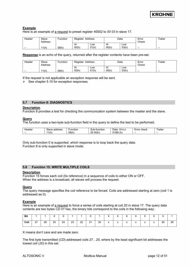
Example Here is an example of a request to preset register 40002 to 00 03 in slave 17.
Register Address Data Header --
Slave Address 11(h)
Function 06(h)
Hi 00(h)
Low 01(h)
Hi 00(h)
Low 03(h)
Error Check --
Trailer --
Response is an echo of the query, returned after the register contents have been pre-set.
Register Address Data Header --
Slave Address 11(h)
Function 06(h)
Hi 00(h)
Low 01(h)
Hi 00(h)
Low 03(h)
Error Check --
Trailer --
If the request is not applicable an exception response will be sent.
See chapter 5.10 for exception responses.
5.7 Function 8: DIAGNOSTICS Description Function 8 provides a test for checking the communication system between the master and the slave. Query The function uses a two-byte sub-function field in the query to define the test to be performed.
Header --
Slave address 11(h)
Function 08(h)
Sub-function 00 00(h)
Data Hi+Lo A1B8 (h)
Error check --
Trailer --
Only sub-function 0 is supported, which response is to loop back the query data. Function 8 is only supported in slave mode.
5.8 Function 15: WRITE MULTIPLE COILS Description Function 15 forces each coil (0x reference) in a sequence of coils to either ON or OFF. When the address is a broadcast, all slaves will process the request. Query The query message specifies the coil reference to be forced. Coils are addressed starting at zero (coil 1 is addressed as 0). Example Here is an example of a request to force a series of coils starting at coil 20 in slave 17. The query data contents are two bytes CD 01 hex, the binary bits correspond to the coils in the following way:
Bit
1 1 0 0 1 1 0 1 0 0 0 0 0 0 0 1
Coil
27 26 25 24 23 22 21 20 x x x x x x 29 28
X means don’t care and are made zero. The first byte transmitted (CD) addressed coils 27…20, where by the least significant bit addresses the lowest coil (20) in this set.
ALTOSONIC V Modbus Manual page 13 of 51
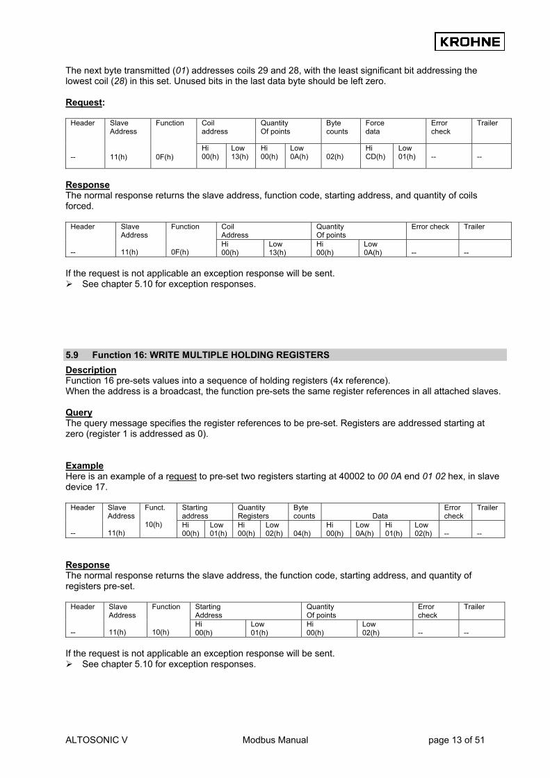
The next byte transmitted (01) addresses coils 29 and 28, with the least significant bit addressing the lowest coil (28) in this set. Unused bits in the last data byte should be left zero. Request:
Coil address
Quantity Of points
Byte counts
Force data
Error check
Trailer
Header --
Slave Address 11(h)
Function 0F(h)
Hi 00(h)
Low 13(h)
Hi 00(h)
Low 0A(h)
02(h)
Hi CD(h)
Low 01(h)
--
--
Response The normal response returns the slave address, function code, starting address, and quantity of coils forced.
Coil Address
Quantity Of points
Error check Trailer
Header --
Slave Address 11(h)
Function 0F(h)
Hi 00(h)
Low 13(h)
Hi 00(h)
Low 0A(h)
--
--
If the request is not applicable an exception response will be sent.
See chapter 5.10 for exception responses.
5.9 Function 16: WRITE MULTIPLE HOLDING REGISTERS Description Function 16 pre-sets values into a sequence of holding registers (4x reference). When the address is a broadcast, the function pre-sets the same register references in all attached slaves. Query The query message specifies the register references to be pre-set. Registers are addressed starting at zero (register 1 is addressed as 0). Example Here is an example of a request to pre-set two registers starting at 40002 to 00 0A end 01 02 hex, in slave device 17.
Starting address
Quantity Registers
Byte counts
Data
Error check
Trailer
Header --
Slave Address 11(h)
Funct. 10(h) Hi
00(h) Low 01(h)
Hi 00(h)
Low 02(h)
04(h)
Hi 00(h)
Low 0A(h)
Hi 01(h)
Low 02(h)
--
--
Response The normal response returns the slave address, the function code, starting address, and quantity of registers pre-set.
Starting Address
Quantity Of points
Error check
Trailer
Header --
Slave Address 11(h)
Function 10(h)
Hi 00(h)
Low 01(h)
Hi 00(h)
Low 02(h)
--
--
If the request is not applicable an exception response will be sent.
See chapter 5.10 for exception responses.

ALTOSONIC V Modbus Manual page 14 of 51
5.10 Exception Responses Except for broadcast messages, a master device expects a normal response, when it sends a query to a slave device. One of the four possible events can occur from the master’s query: 1. If the slave device receives the query without a communication error and can handle the query
normally, it returns a normal response. 2. If the slave does not receive the query due to a communication error, no response is returned. The
master program will eventually process a timeout condition for the query. 3. If the slave receives the query, but detects a communication error (parity, CRC, LRC), no response is
returned. The master program will eventually process a timeout condition for the query. 4. If the slave receives the query without a communication error, but cannot handle it, the slave will return
an exception response informing the master of the nature of the error. The exception response message has two fields that differentiate it from a normal response: 1 the function code field; and 2 the data field. Ad 1 Function Code Field In a normal response the slave echoes the function code of the original query in the function code field of the response. All function codes have a most significant bit of 0. In an exception response the slave sets the most significant bit of the function code to 1. The master recognises the exception response by means of this bit and can examine the data field for the exception code. Ad 2 Data field In an exception response the slave returns an exception code in the data field. This defines the slave condition that caused the exception. The exception response message:
Header Slave address Function Exception code Error check Trailer Exception codes
Code Name Meaning 01 Illegal function The function code in the query is not an allowable action for the slave. 02 Illegal data address The data address received in the query is not an allowable address for the slave.

ALTOSONIC V Modbus Manual page 15 of 51
6 HANDLING OF LARGE DATA TYPES The standard Modbus specification does not explain how data types larger than 16 bits should be handled. The standard Modbus functions to modify holding registers are used for handling larger data types. Function 03 (read multiple holding registers), function 06 (write single holding register), and function 16 (write multiple holding registers) are used to read or modify these data types. In the UFP-V each register-area contains a data type. In order to maintain compatibility with older systems, a parameter 5.2 MODBUS_MODICON_COMPAT controls how the registers are counted. In modicon compatible mode the data is counted as 16 bit registers. In not-modicon compatible mode the data is counted on the data type, so a float is one register! Notice that function 6 in not-modicon compatible mode will also write one type of the accompanying data type! The supported data types are: • Integer (16 bit) • Long integer (32 bit) • Float (32 bit) • Double (64 bit) The register ranges for each data type:
Number of registers to request for each data type Function Address (default)
Data type Modicon
compatible Not Modicon compatible
1,2,5,15 1000..2999 Boolean 1 1 3000..3999 Integer 1 1 5000..5999 Long integer 2 1 6000..6999 Double 4 1
3,4,6,16
7000..7999 Float 2 1 Notice that in modicon compatible mode each data type larger than 16 bits should be addressed as 16 bit registers. For instance the first float is located on address 7000/7001 the next float is located on address 7002/7003. A double would be accessed by four 16-bit registers, so the first double 6000/6001/6002/6003 and the next double 6004/6005/6006/6007. The data in the chapter 8.4 Modbus Mapping Assignments is printed as it should be accessed in not-modicon compatible mode.

ALTOSONIC V Modbus Manual page 16 of 51
6.1 Floating Point Representation The exponent is biased by 127. The mantissa is 24 bits with the most significant bit 1 (not stored), 23 bit stored.
Biased exponent Mantissa 3 (high) Mantissa 2 Mantissa 1 (low) SEEE EEEE E MMM MMMM MMMM MMMM MMMM MMMM
6.2 Double Representation The exponent is biased by 1023. The mantissa is 53 bits with the most significant bit 1 (not stored), 52 bits stored.
Biased exponent Exp+Mantissa Mantissa 6 Mantissa 5 SEEE EEEE EEEE MMMM MMMM MMMM MMMM MMMM
Mantissa 4 Mantissa 3 Mantissa 2 Mantissa 1 MMMM MMMM MMMM MMMM MMMM MMMM MMMM MMMM
6.3 Transmit Sequence Integers are transmitted and stored with the most significant part first. Example Integer value 1790 decimal (6FE hexadecimal) is transmitted as:
First transmitted byte in data field Second transmitted byte in data field 06 FE
Long integers could be transmitted in two possible ways: Example Long integer value 305419896 (12345678 hexadecimal) The transmit order in both modes:
Normal mode (1) 12h
(2) 34h
(3) 56h
(4) 78h
Reversed mode (3) 56h
(4) 78h
(1) 12h
(2) 34h
Floats could be transmitted in two ways: Example: The float number 4.125977 will give the IEEE representation.
S EXPONENT MANTISSA 0 1000 0001 (1) 000 0100 0000 1000 0000 0000
• A biased exponent of 129 (81 hexadecimal) is exponent 2. • A positive sign • Mantissa = 4 + 1/8 + 1/1024. Note that the first bit is not stored!
ALTOSONIC V Modbus Manual page 17 of 51
The transmit order in both modes:
IEEE (1) 40h
(2) 84h
(3) 08h
(4) 00h
Normal mode (1) 40h
(2) 84h
(3) 08h
(4) 00h
Reversed mode (3) 08h
(4) 00h
(1) 40h
(2) 84h
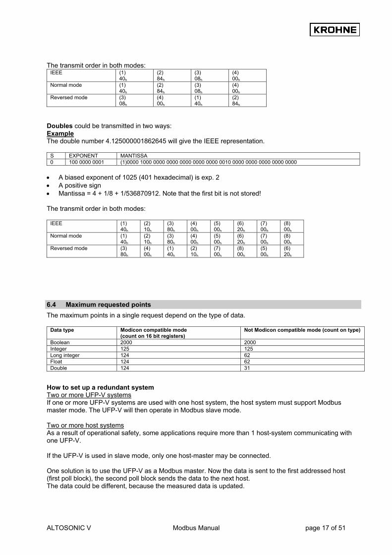
Doubles could be transmitted in two ways: Example The double number 4.125000001862645 will give the IEEE representation.
S EXPONENT MANTISSA 0 100 0000 0001 (1)0000 1000 0000 0000 0000 0000 0000 0010 0000 0000 0000 0000 0000
• A biased exponent of 1025 (401 hexadecimal) is exp. 2 • A positive sign • Mantissa = 4 + 1/8 + 1/536870912. Note that the first bit is not stored! The transmit order in both modes:
IEEE (1) 40h
(2) 10h
(3) 80h
(4) 00h
(5) 00h
(6) 20h
(7) 00h
(8) 00h
Normal mode (1) 40h
(2) 10h
(3) 80h
(4) 00h
(5) 00h
(6) 20h
(7) 00h
(8) 00h
Reversed mode (3) 80h
(4) 00h
(1) 40h
(2) 10h
(7) 00h
(8) 00h
(5) 00h
(6) 20h
6.4 Maximum requested points The maximum points in a single request depend on the type of data.
Data type Modicon compatible mode (count on 16 bit registers)
Not Modicon compatible mode (count on type)
Boolean 2000 2000 Integer 125 125 Long integer 124 62 Float 124 62 Double 124 31
How to set up a redundant system Two or more UFP-V systems If one or more UFP-V systems are used with one host system, the host system must support Modbus master mode. The UFP-V will then operate in Modbus slave mode. Two or more host systems As a result of operational safety, some applications require more than 1 host-system communicating with one UFP-V. If the UFP-V is used in slave mode, only one host-master may be connected. One solution is to use the UFP-V as a Modbus master. Now the data is sent to the first addressed host (first poll block), the second poll block sends the data to the next host. The data could be different, because the measured data is updated.

ALTOSONIC V Modbus Manual page 18 of 51
Another solution is to send the data to the hosts by means of a broadcast. Now all host systems receive the same data.

ALTOSONIC V Modbus Manual page 19 of 51
7 SET-UP OF THE UFP-V MODBUS DRIVER
7.1 Driver Contents The driver contains: • Standard Modbus protocol according to Modicon. • Simulation of Modbus Master and Slave mode. • ASCII-mode and RTU mode. • Half and full duplex communication layers supported. • Transmitter ON/OFF level select for half-duplex mode. • Seven or eight data bits, Even/Odd/No parity, 1 or 2 stop bits • Extended data type support. • Function 1, 2, 3, 4, 5, 6, 8,15,16 including exception generation.
7.2 Hardware set-up To set up the Modbus communication first the hardware should be set-up. The UFP is equipped with a RS485/RS422 Communication Card which provide 2 serial communication channels, the first channel CH1 is used for the communication with the UFC-V, please do not change anything here. The second channel CH2 is free for communication with host systems . There are two generations of RS485 cards: • AX4285A formerly installed • PCL745s currently installed

ALTOSONIC V Modbus Manual page 20 of 51
7.2.1 RS485/422 card: AX4285A
The first generation of RS 485 cards used DIP SWITCH CH1*** : COM 3 Baseaddress ch#1: 3E8 DIP SWITCH CH2*** : COM 4 Baseaddress ch#2: 2E8 JP1*** : COM3 Interrupt IRQ4 JP2*** : COM4 Interrupt IRQ3 JP3*** : COM3 RS 485 mode JP4*** : COM3 Serial resistors enabled, No jumpers installed JP5 : COM4 RS 485 mode as default JP6 : COM4 Serial resistors not enabled, jumpers installed ***(=Krohne Altometer setting) NOTE: RS485 mode and RS422 mode for COM4 (Modbus) differs in set-up by: - Jumper JP5 RS485 or RS422 - The external wiring for RS422 and RS485 External wiring AX5285A for Modbus: The resistors of 120 Ohm must be placed at the ALTOSONIC-V wiring terminal

ALTOSONIC V Modbus Manual page 21 of 51
7.2.2 RS485/422 card: PCL-745 S
The current generation RS485/422 card Dip switch ch1*** : COM 3 Address 3E8 (Krohne Altometer setting) Dip switch ch2*** : COM4 Address 2E8 JP1*** : Interrupt COM3 IRQ4 JP2*** : Interrupt COM4 IRQ3 JP4*** : Transmit driver enable COM3 always RTS JP5 : Transmit driver enable COM4 default RTS JP6*** : Receive COM3 (422 is always on) JP7*** : Terminator jumper COM3 120 JP8*** : Terminator jumper COM3 always not installed JP9*** : Receive COM4 (422 is always on) JP10*** : Terminator jumper COM4 120 JP11 : Terminator jumper COM4 (120 for RS422 mode, not installed for RS485 mode) ***(=Krohne Altometer setting) NOTE: JP6 and JP9 are always 422 because the receiver is for both RS485 mode and RS422 mode expected to be enabled for the UFP-Program. RS485 mode and RS422 mode for COM4 (Modbus) therefore only differs in set up by: - Jumper JP11 not installed (RS485) or installed on 120 (RS422) - The external wiring for RS422 and RS485 External wiring PCL745 for Modbus:

ALTOSONIC V Modbus Manual page 22 of 51
7.3 Software set-up Now set-up the software, all the settings for the Modbus driver is done in the file [coms0300.dat]. See also chapter 9.4 Appendix D: Coms0300.dat file
7.3.1 First set the parameters for the communication line
• 3.1 MODBUS_UART_BASEADRESS for channel 1 is COM4 this is baseaddress 0x2E8 • 3.2 MODBUS_UART_INTERRUPT is for COM4 set to interrupt 3. • Depends on your application : 3.3 MODBUS_UART_BAUDRATE 1200,2400,4800,9600,19200 • 3.4 MODBUS_UART_RTS_MODE to 0. • Depends on your application : 3.5 MODBUS_UART_N_DATABITS to 7 or 8 • Depends on your application : 3.6 MODBUS_UART_N_STOPBITS to 1 or 2 • Depends on your application : 3.7 MODBUS_UART_PARITY to none, even or odd. • Depends on your application : 3.3 MODBUS_UART_BAUDRATE 1200,2400,4800,9600,19200 • Depends on your application :
If you use RS485 set 3.8 MODBUS_UART_HALF_DUPLEX to HALF_DUPLEX(=1) If you use RS422 set 3.8 MODBUS_UART_HALF_DUPLEX to FULL_DUPLEX(=0)
7.3.2 Now select the parameters for the used protocol
• Select the frame type RTU or ASCII with 3.9 MODBUS_TRANSFER_MODE. • Set the UFP-V as MASTER or SLAVE device with 5.1 MODBUS_DEVICE_TYPE. • Select if variables, which are larger than 16 bits are still counted as the number of 16 bit • Set the data points requesting type by parameter 5.2 MODBUS_MODICON_COMPAT:
By type is not modicon compitable ( =0) By 16 bit registers is modicon compitable ( =1)
•
7.3.3 The UFP-V as SLAVE device
The slave mode is activated when the parameter 5.1 MODBUS_DEVICE_TYPE=1. • If the UFP-V acts like a Modbus Slave device, set the SlaveID with 5.3 MODBUS_SLAVE_ID. • The 5.4 FLAG_HOLD_TIME is a hold time on the status flags (Booleans only).
The 5.4 FLAG_HOLD_TIME freezes the flags after the flag has changed from state. Set this time a bit larger than the maximum communication-request interval.
• The next fields define to which Modbus addresses the data of the UFP-V is mapped to, these settings are default settings and should not be changed, only if necessary. The fields are 6 DATAFIELD 1 to N, for every DATAFIELD an access mode could be set. The 6 ACCES MODE defines how the data is send and interpreted when the UFP-V is in slave-mode.
• See the manual of the accompanying byte-order of transmission/reception with the 2 modes.
For Slave-use the driver should be working now.

ALTOSONIC V Modbus Manual page 23 of 51
7.3.4 The UFP-V as Master
The master mode is activated when the parameter 5.1 MODBUS_DEVICE_TYPE=2. For master mode the UFP-V must know what it should send to the connected slave device, therefore the master works with poll blocks. Each poll block defines how a transaction should take place i.e. which slave is addressed, which registers are read or write and how to do it. The maximum number of poll blocks to define is 20. The number of poll blocks to use is set with the parameter 7.1 NUMBER_OF_POLLBLOCKS_TO_USE. During start-up of the UFP-V, a poll block validation check will be done. Only the number of poll blocks defined in 7.1 NUMBER_OF_POLLBLOCKS_TO_USE will be checked. The maximum response time after a poll block request is set by the parameter 7.2 REQUEST_TO_RESPONSE_TIMEOUT. If no response is received from the slave within this time, a poll block timeout error is generated. So for every pollblock (=data movement) set : • The 7.3a SLAVEID : the address of the slave device , notice that 0 is a broadcast to all slaves, not all
the functions are allowed with broadcast messages. • The 7.3b MASTER REGISTER, this is the location of the data in the UFP-V. • The 7.3c SLAVE REGISTER, this is the location of the data in the slave device. • The 7.3d N_POINTS, this is always the number data points of the specific datatype to transfer, like 1
Boolean, 1 int, 1 float. The real number of 16 bit registers in the Modbus message is calculated. For instance, in modicon compatible mode the number of registers in the message is always 2 times the number of floats. In not-modicon compatible mode the number of registers in the message is always the same as number of floats. So number of points in the pollblock definition always count the datatypes.
• The 7.3e FUNCTION selects which Modbus function is used for the data transfer (see a complete list in the manual).
• The 7.3f DATATYPE is for internal validation only but should be filled in correctly. • The 7.3g DATANOTATION defines in which byte-order the data is send, float, longs, doubles may be
send with different notations (like big and little indian). • The 7.3h DELAY is the time to wait after the last pollblock has been send before sending the next
pollblock. When all the pollblocks are defined, select with 7.1 NUMBER_OF_POLLBLOCKS_TO_USE, which pollblocks to use. 1=first one only, 2 is number one and two …and so on.
ALTOSONIC V Modbus Manual page 24 of 51
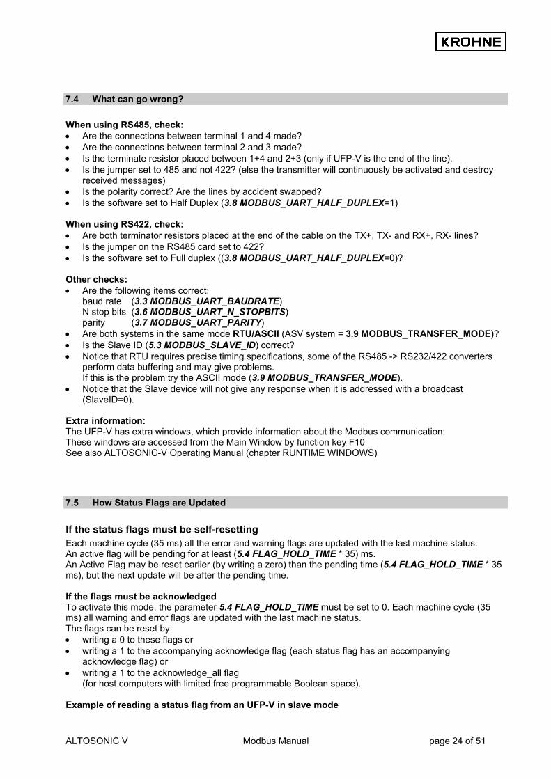
7.4 What can go wrong? When using RS485, check: • Are the connections between terminal 1 and 4 made? • Are the connections between terminal 2 and 3 made? • Is the terminate resistor placed between 1+4 and 2+3 (only if UFP-V is the end of the line). • Is the jumper set to 485 and not 422? (else the transmitter will continuously be activated and destroy
received messages) • Is the polarity correct? Are the lines by accident swapped? • Is the software set to Half Duplex (3.8 MODBUS_UART_HALF_DUPLEX=1) When using RS422, check: • Are both terminator resistors placed at the end of the cable on the TX+, TX- and RX+, RX- lines? • Is the jumper on the RS485 card set to 422? • Is the software set to Full duplex ((3.8 MODBUS_UART_HALF_DUPLEX=0)? Other checks: • Are the following items correct:
baud rate (3.3 MODBUS_UART_BAUDRATE) N stop bits (3.6 MODBUS_UART_N_STOPBITS) parity (3.7 MODBUS_UART_PARITY)
• Are both systems in the same mode RTU/ASCII (ASV system = 3.9 MODBUS_TRANSFER_MODE)? • Is the Slave ID (5.3 MODBUS_SLAVE_ID) correct? • Notice that RTU requires precise timing specifications, some of the RS485 -> RS232/422 converters
perform data buffering and may give problems. If this is the problem try the ASCII mode (3.9 MODBUS_TRANSFER_MODE).
• Notice that the Slave device will not give any response when it is addressed with a broadcast (SlaveID=0).
Extra information: The UFP-V has extra windows, which provide information about the Modbus communication: These windows are accessed from the Main Window by function key F10 See also ALTOSONIC-V Operating Manual (chapter RUNTIME WINDOWS)
7.5 How Status Flags are Updated
If the status flags must be self-resetting Each machine cycle (35 ms) all the error and warning flags are updated with the last machine status. An active flag will be pending for at least (5.4 FLAG_HOLD_TIME * 35) ms. An Active Flag may be reset earlier (by writing a zero) than the pending time (5.4 FLAG_HOLD_TIME * 35 ms), but the next update will be after the pending time. If the flags must be acknowledged To activate this mode, the parameter 5.4 FLAG_HOLD_TIME must be set to 0. Each machine cycle (35 ms) all warning and error flags are updated with the last machine status. The flags can be reset by: • writing a 0 to these flags or • writing a 1 to the accompanying acknowledge flag (each status flag has an accompanying
acknowledge flag) or • writing a 1 to the acknowledge_all flag
(for host computers with limited free programmable Boolean space). Example of reading a status flag from an UFP-V in slave mode

ALTOSONIC V Modbus Manual page 25 of 51
The status flag is read by the master. 1. If the status flag is active,
the master uses this state to perform its actions and sends an acknowledgement to the UFP-V by setting the accompanying ACK_flag to 1. Now the UFP-V updates the status flag with the actual status. Note that in this mode the status flag remains active until the acknowledge is given.
2. If the status flag is not active, the master removes the acknowledge by resetting the ACK_flag.
Example of reading status flag 0 from an UFP-V in master mode 1. The first poll block sends the status flag to the master 2. If the status flag is active, the master uses this status to perform his actions and sends an
acknowledgement to UFP-V by means of setting the accompanying ACK_flag to 1. 3. The next poll block reads this ACK_FLAG and updates it in the UFP-V,
now the UFP-V updates the status flag with the actual status. 3. If the flag is not active, the master removes the acknowledgement by resetting the ACK_flag. As long as the ACK_flag is active the status flag is updated every 35 milliseconds. If the communication speed is known, choose the 5.4 FLAG_HOLD_TIME large enough to give the host the possibility to detect the state of the flags. To set-up a more secure system use the acknowledge method. A disadvantage is the increase in communication time. 5.4 FLAG_HOLD_TIME is located in the coms0300.dat file. See also chapter 9.4 Appendix D: Coms0300.dat file

ALTOSONIC V Modbus Manual page 26 of 51
7.6 How data is written to the float field Field 6 (addresses are default mapped to address 7500) is the read/write field for floats. Current applications for writing to the UFP-V system are: 1. API settings for the parameters used in the UFP-Program for calculating Standard/Mass flow and
totals. The addresses used are 7501…7514 for floats and 2068…2069, 2201.. 2214 for Booleans 2. External flow meter settings for the parameters used in the UFP-Program for proving an external
flow meter such as a turbine meter. Connection is established through a pulse input and temperature and pressure at external conditions. The addresses used are 7521…7523 for floats and 2070, 2071, 2221… 2223 for Booleans
3. System time deviation
The UFP-Program has a system time that can be altered by input of deviation [s] on current system time. In file COMS0300.dat section 5.6 this must be configured to enable the writing. For current system time see Integers 3033…3038 The addresses used for writing are 7577 for floats and 2230 for Booleans.
4. Densito meter calibration data
The UFP-Program can measure the density with a densito meter. There are 4 data sets, 2 for Solartron and 2 for Sarasota. See Floats 7531…7566 and Booleans 2231…2241 for writing the data.
5. Override values on secondary inputs
In the UFP-Program it is possible to manually override the secondary input values when the specific parameter is used in the calculation and the Alarm output is enabled in the Initialisation file CLNT0300.dat See Floats 7578…7588 and Booleans 2072…2081 and 2243…2255.
6. UFP Batch control (internal batch)
The UFP-Program is capable of batching. A serial printer connected to the UFP prints tickets. This batch control is done by a single float 7530 that handles specific float values as control commands. On success the float value returns 1 on not permitted returns 0. For status on batch control etc. see Integers 3020…3023 and Long 5008. Internal UFP-Program batch is done by batch1 values see Float 7077…7127.
7. Secondary inputs through Modbus communication
Instead of using AD or frequency input it is possible to measure a secondary input through Modbus. Note that this must be configured in the CLNT0300.dat file section 9. The time out value on new input can be configured in file COMS0300.dat section 5.5. If the new value is not written before this timeout value elapses the specific input generates an alarm. After every new input value, the time out counter is reset. See Floats 7567…7576.
Applications 1…5 can only be accessed for writing when first a Boolean is set that enables writing for 30 seconds. This is described in the next paragraph 7.6.1
7.6.1 How to write in the float field to the specific application
Applications 1…5 can only be accessed for writing when first a Boolean is set that enables writing for 30 seconds. How to handle:
ALTOSONIC V Modbus Manual page 27 of 51
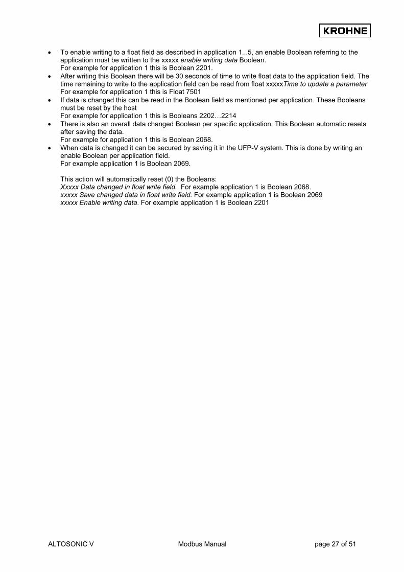
• To enable writing to a float field as described in application 1...5, an enable Boolean referring to the application must be written to the xxxxx enable writing data Boolean. For example for application 1 this is Boolean 2201.
• After writing this Boolean there will be 30 seconds of time to write float data to the application field. The time remaining to write to the application field can be read from float xxxxxTime to update a parameter For example for application 1 this is Float 7501
• If data is changed this can be read in the Boolean field as mentioned per application. These Booleans must be reset by the host For example for application 1 this is Booleans 2202…2214
• There is also an overall data changed Boolean per specific application. This Boolean automatic resets after saving the data. For example for application 1 this is Boolean 2068.
• When data is changed it can be secured by saving it in the UFP-V system. This is done by writing an enable Boolean per application field. For example application 1 is Boolean 2069. This action will automatically reset (0) the Booleans: Xxxxx Data changed in float write field. For example application 1 is Boolean 2068. xxxxx Save changed data in float write field. For example application 1 is Boolean 2069 xxxxx Enable writing data. For example application 1 is Boolean 2201
ALTOSONIC V Modbus Manual page 28 of 51
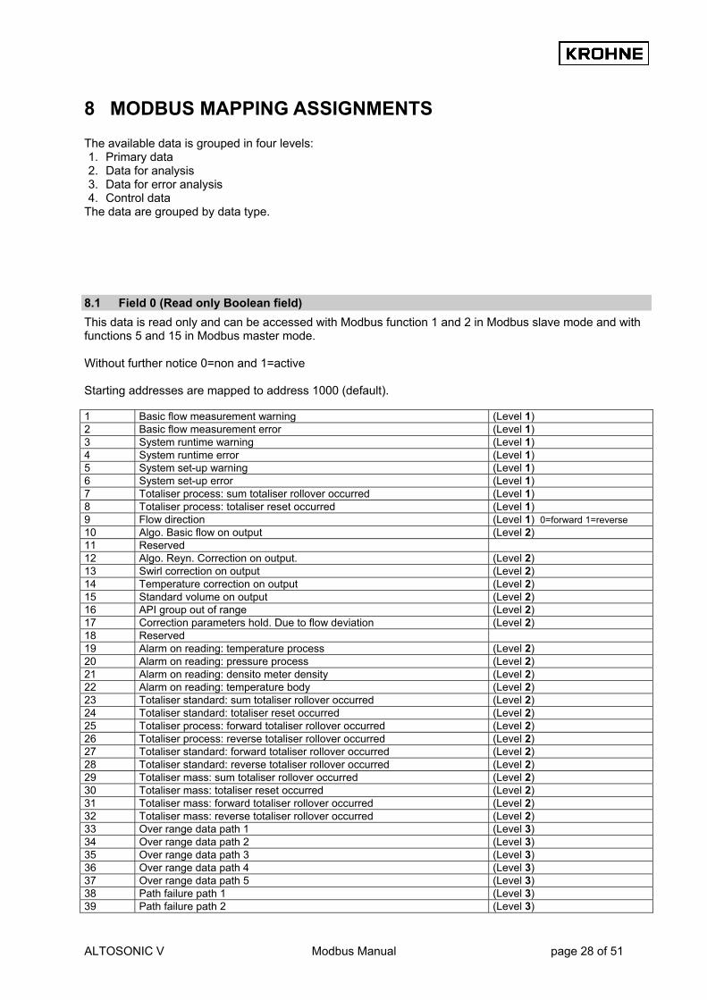
8 MODBUS MAPPING ASSIGNMENTS The available data is grouped in four levels: 1. Primary data 2. Data for analysis 3. Data for error analysis 4. Control data
The data are grouped by data type.
8.1 Field 0 (Read only Boolean field) This data is read only and can be accessed with Modbus function 1 and 2 in Modbus slave mode and with functions 5 and 15 in Modbus master mode. Without further notice 0=non and 1=active Starting addresses are mapped to address 1000 (default). 1 Basic flow measurement warning (Level 1) 2 Basic flow measurement error (Level 1) 3 System runtime warning (Level 1) 4 System runtime error (Level 1) 5 System set-up warning (Level 1) 6 System set-up error (Level 1) 7 Totaliser process: sum totaliser rollover occurred (Level 1) 8 Totaliser process: totaliser reset occurred (Level 1) 9 Flow direction (Level 1) 0=forward 1=reverse 10 Algo. Basic flow on output (Level 2) 11 Reserved 12 Algo. Reyn. Correction on output. (Level 2) 13 Swirl correction on output (Level 2) 14 Temperature correction on output (Level 2) 15 Standard volume on output (Level 2) 16 API group out of range (Level 2) 17 Correction parameters hold. Due to flow deviation (Level 2) 18 Reserved 19 Alarm on reading: temperature process (Level 2) 20 Alarm on reading: pressure process (Level 2) 21 Alarm on reading: densito meter density (Level 2) 22 Alarm on reading: temperature body (Level 2) 23 Totaliser standard: sum totaliser rollover occurred (Level 2) 24 Totaliser standard: totaliser reset occurred (Level 2) 25 Totaliser process: forward totaliser rollover occurred (Level 2) 26 Totaliser process: reverse totaliser rollover occurred (Level 2) 27 Totaliser standard: forward totaliser rollover occurred (Level 2) 28 Totaliser standard: reverse totaliser rollover occurred (Level 2) 29 Totaliser mass: sum totaliser rollover occurred (Level 2) 30 Totaliser mass: totaliser reset occurred (Level 2) 31 Totaliser mass: forward totaliser rollover occurred (Level 2) 32 Totaliser mass: reverse totaliser rollover occurred (Level 2) 33 Over range data path 1 (Level 3) 34 Over range data path 2 (Level 3) 35 Over range data path 3 (Level 3) 36 Over range data path 4 (Level 3) 37 Over range data path 5 (Level 3) 38 Path failure path 1 (Level 3) 39 Path failure path 2 (Level 3)

ALTOSONIC V Modbus Manual page 29 of 51
40 Path failure path 3 (Level 3) 41 Path failure path 4 (Level 3) 42 Path failure path 5 (Level 3) 43 Deviation in sound velocity path 1 (Level 3) 44 Deviation in sound velocity path 2 (Level 3) 45 Deviation in sound velocity path 3 (Level 3) 46 Deviation in sound velocity path 4 (Level 3) 47 Deviation in sound velocity path 5 (Level 3) 48 Communication failure path 1 (Level 3) 49 Communication failure path 2 (Level 3) 50 Communication failure path 3 (Level 3) 51 Communication failure path 4 (Level 3) 52 Communication failure path 5 (Level 3) 53 Real profile sampling on hold. Due to channel failures or flow deviation (Level 2) 54 Alarm on reading: external viscosity (Level 2) 55 Alarm on reading: temperature densito meter (Level 2) 56 Alarm on reading: pressure densito meter (Level 2) 57 Alarm on reading: temperature proving (external flow meter) (Level 2) 58 Alarm on reading: pressure proving (external flow meter) (Level 2) 59 Densito meter switch alarm (Level 2) 60 Real profile out of range during correction of channel(s) (Level 2) 61 Alarm on reading: standard density input (Level 2) 62 Alarm on service value: temperature body (Level 2) 63 Alarm on service value: temperature process (Level 2) 64 Alarm on service value: temperature proving (external flow meter) (Level 2) 65 Alarm on service value: temperature densito meter (Level 2) 66 Alarm on service value: pressure process (Level 2) 67 Alarm on service value: pressure proving (external flow meter) (Level 2) 68 Alarm on service value: pressure densito meter (Level 2) 69 Alarm on service value: densito meter density (Level 2) 70 Alarm on service value: standard density (Level 2) 71 Alarm on service value: viscosity external (Level 2) 72 Override enable possible for temperature body (Level 1) 73 Override enable possible for temperature process (Level 1) 74 Override enable possible for temperature proving (external flow meter) (Level 1) 75 Override enable possible for temperature densito meter (Level 1) 76 Override enable possible for pressure process (Level 1) 77 Override enable possible for pressure proving (external flow meter) (Level 1) 78 Override enable possible for pressure densito meter (Level 1) 79 Override enable possible for density densito meter (Level 1) 80 Override enable possible for density standard (Level 1) 81 Override enable possible for viscosity external (Level 1) 82 Override default (automatic) temperature body (Level 2) if enabled in CLNT0300.dat 83 Override default (automatic) temperature process (Level 2) if enabled in CLNT0300.dat 84 Override default (automatic) temperature proving (external flow meter) (Level 2) if enabled in CLNT0300.dat 85 Override default (automatic) temperature densito meter (Level 2) if enabled in CLNT0300.dat 86 Override default (automatic) pressure process (Level 2) if enabled in CLNT0300.dat 87 Override default (automatic) pressure proving (external flow meter) (Level 2) if enabled in CLNT0300.dat 88 Override default (automatic) pressure densito meter (Level 2) if enabled in CLNT0300.dat 89 Override default (automatic) density densito meter (Level 2) if enabled in CLNT0300.dat 90 Override default (automatic) density standard (Level 2) if enabled in CLNT0300.dat 91 Override default (automatic) viscosity external (Level 2) if enabled in CLNT0300.dat 92 Batch valid. The last batch completed (no save after program stop) (Level 1) 0=not valid, 1=valid 93…128 Reserved

ALTOSONIC V Modbus Manual page 30 of 51
8.2 Field 1 (Read/Write Boolean Field) These data can be accessed with Modbus function 1, 2, 5 and 15. Starting addresses are mapped to address 2000 (default). Without further notice 0=non and 1=active 1…64 Acknowledge_flags_field_0 (Level 1) 65. General_acknowledge_flags_field_0 (Level 1) 66. Reset all errors (Level 4) automatic reset 67. Reset all totalisers and all errors (Level 4) automatic reset 68. API: data changed in float write field (API 202...214) (Level 1) automatic reset 69. API: save changed data in float write field (API 202...214) (Level 4) automatic reset 70. EXT: data changed in float write field (EXT 222...223) (Level 1) automatic reset 71. EXT: save changed data in float write field (EXT 222...223) (Level 4) automatic reset 72. EXT: restart proving of external flow meter (Level 4) automatic reset 73. Batch 1 reset averages
For Continuous Pipe Line Measurement by host , not for the UFP internal CPL batch mode
(Level 4) automatic reset
74 Batch 2 reset averages For Continuous Pipe Line Measurement by host
(Level 4) automatic reset
75 Modbus output for all totalisers and batch 1+2 values on hold for 30 sec. (Internally all totalisers continue)
(Level 4) automatic reset or write 0 to release
76…200 Reserved 201. API enable writing data (Level 4) reset after 30 sec 202. API change in: correction type (Level 1) manual reset 203. API change in: density standard type (Level 1) manual reset 204. API change in: fluid type (Level 1) manual reset 205. API change in: stand. density crude (fluid type 0) (Level 1) manual reset 206. API change in: stand. density gasoline (fluid type 1) (Level 1) manual reset 207. API change in: stand. density trans.area(fluid type 2) (Level 1) manual reset 208. API change in: stand. density jet group (fluid type 3) (Level 1) manual reset 209. API change in: stand. density fuel oil (fluid type 4) (Level 1) manual reset 210. API change in: stand. density free fill (fluid type 5) (Level 1) manual reset 211. API change in: free fill K0 (Level 1) manual reset 212. API change in: free fill K1 (Level 1) manual reset 213. API change in: free fill K2 (Level 1) manual reset 214. API change in: temperature standard (Level 1) manual reset 215...220 Reserved 221. EXT enable writing data (Level 4) automatic reset 30 s 222. EXT change in: K-factor external flow meter (Level 1) manual reset 223. EXT change in: parameters changeable under flowing condition or under
low flow cut-off (Level 1) manual reset
224…229 Reserved 230 SYSTEM TIME deviation enable writing (see float 7577) (Level 4) if enabled in set-up 231. SOLARTRON1 enable writing data (Level 4) automatic reset 30 s 232. SOLARTRON1 change in: calibration data (Level 1) automatic reset 233. SOLARTRON1 save and enable written data (Level 1) automatic reset 234. SOLARTRON2 enable writing data (Level 4) automatic reset 30 s 235. SOLARTRON2 change in: calibration data (Level 1) automatic reset 236. SOLARTRON2 save and enable written data (Level 1) automatic reset 237. SARASOTA1 enable writing data (Level 4) automatic reset 30 s 238. SARASOTA1 change in: calibration data (Level 1) automatic reset 239. SARASOTA1 save and enable written data (Level 1) automatic reset 240. SARASOTA2 enable writing data (Level 4) automatic reset 30 s 241. SARASOTA2 change in: calibration data (Level 1) automatic reset 242. SARASOTA2 save and enable written data (Level 1) automatic reset 243. OVERRIDE enable writing data (Level 4) automatic reset 30 s 244. OVERRIDE change in: override data (Level 1) automatic reset 245. OVERRIDE save and enable written data (Level 1) automatic reset 246. OVERRIDE enable to set value Temperature Body (Level 4) if enable to override 247. OVERRIDE enable to set value Temperature Process (Level 4) if enable to override 248. OVERRIDE enable to set value Temperature Proving (external flow (Level 4) if enable to override

ALTOSONIC V Modbus Manual page 31 of 51
meter) 249. OVERRIDE enable to set value temperature densito meter (Level 4) if enable to override 250. OVERRIDE enable to set value pressure process (Level 4) if enable to override 251. OVERRIDE enable to set value pressure proving (external flow meter) (Level 4) if enable to override 252. OVERRIDE enable to set value pressure densito meter to override (Level 4) if enable to override 253. OVERRIDE enable to set value density densito meter to override (Level 4) if enable to override 254. OVERRIDE enable to set value density standard to override (Level 4) if enable to override 255. OVERRIDE enable to set value viscosity dynamic to override (Level 4) if enable to override 256…320 Reserved Reset totalisers will automatically reset the rollover bits of all totalisers, alarms and process time.
8.3 Field 2 (Read only Integer Field) This data is read only and can be accessed with Modbus function 3 and 4 in Modbus slave mode and with functions 6 and 16 in Modbus master mode. Starting addresses are mapped to address 3000 (default). 1 Flow process (Level 1) scaled –32768…32767 -125%… +125% 2 Sound velocity average (Level 1) scaled –32768…32767 -3276.8…3276.7 m/s 3 Temperature process (Level 1) scaled –32768…32767 -327.68…327.67 °C 4 Pressure process (Level 1) scaled –32768…32767 -327.68…327.67 Bar 5 Density process (Level 1) scaled 0...32767 0…1638.35 kg/m3 6 Temperature body (Level 1) scaled –32768…32767 -327.68...327.67 °C 7 Flow standard (Level 1) scaled –32768…32767 -125% …+125% 8 Flow mass (Level 1) scaled –32768…32767 -125% …+125% 9 Flow of channel 1 (Level 2) scaled –32768…32767 -125% …+125% 10 Flow of channel 2 (Level 2) scaled –32768…32767 -125% …+125% 11 Flow of channel 3 (Level 2) scaled –32768…32767 -125% …+125% 12 Flow of channel 4 (Level 2) scaled –32768…32767 -125% …+125% 13 Flow of channel 5 (Level 2) scaled –32768…32767 -125% …+125% 14 Sound velocity of channel 1 (Level 2) scaled 0…32767 0…3276.7 m/s 15 Sound velocity of channel 2 (Level 2) scaled 0…32767 0…3276.7 m/s 16 Sound velocity of channel 3 (Level 2) scaled 0…32767 0…3276.7 m/s 17 Sound velocity of channel 4 (Level 2) scaled 0…32767 0…3276.7 m/s 18 Sound velocity of channel 5 (Level 2) scaled 0…32767 0…3276.7 m/s 19 Density meter choice (Level 2) 0=AD /Modbus input
1=Solartron1 2=Solartron2 3=Sarasota 1 4=Sarasota2 5=Freq-span
20 UFP batch1 ticket number (Level 1) 0…32767 21 UFP batch1 status (Level 1) 0=non
1=setup 2=running 3=end-batch 5=end-printing 6=end-printfail 7=confirm 10=reset
22 UFP batch1 printer status (Level 1) 0=Ready to print 1=Fail in printing 2=Busy (During print task) 2=Check for printer connection (when no print task) 3=No printer connection
23 UFP batch1 print task (Level 1) 0 =No print task 1…2 =Attempt to print first character of header 3 =Time out value countdown for actual printing 4…98=Printing headers

ALTOSONIC V Modbus Manual page 32 of 51
99 =Successful printing batch ticket 100 =Ready to confirm print task 101 =Ready to reset on batch status RESET
24 Reserved 25 System set-up warning/error number (Level 3) 26 System runtime warning/error number (Level 3) 27 System messages 01…16 (Level 3) 28 System messages 17…32 (Level 3) 29 System messages 33…48 (Level 3) 30 System messages 49…64 (Level 3) 31 Number of current warnings (Level 3) 32 Number of current alarms (Level 3) 33 SYSTEM TIME: seconds (Level 1) 0…59 34 SYSTEM TIME: minutes (Level 1) 0…59 35 SYSTEM TIME: Hours (Level 1) 0…23 36 SYSTEM TIME: Day (Level 1) 1…31 37 SYSTEM TIME: Month (Level 1) 1…12 38 SYSTEM TIME: Year (Level 1) 2001… 39…40 Reserved

ALTOSONIC V Modbus Manual page 33 of 51
8.4 Field 3 (Read only Long Integer Field) This data is read only and can be accessed with Modbus function 3 and 4 in Modbus slave mode and with functions 6 and 16 in Modbus master mode. Starting addresses are mapped to address 5000 (default). 1 Resetable totaliser: process sum (Level 1) Value in Liters 2 Flow: process (Level 1) scaled -32768 ... +32767 -125% …+125% 3 Sound velocity average (Level 1) scaled 0…32767 0…3276.7 m/s 4 Resetable totaliser: standard sum (Level 1) Value in Liters 5 Flow: standard (Level 1) scaled -32768 … +32767 -125%… +125% 6 Resetable totaliser: mass sum (Level 1) Value in Kilograms 7 Flow: mass (Level 1) scaled -32768 … +32767 -125%… +125% 8 UFP batch1 ticket count (Level 1) 0….2147483647 9 Resetable totaliser: process forward (Level 1) Value in liters 10 Resetable totaliser: process reverse (Level 1) Value in liters 11 Resetable totaliser: standard forward (Level 1) Value in liters 12 Resetable totaliser: standard reverse (Level 1) Value in liters 13 Resetable totaliser: mass forward (Level 1) Value in kilograms 14 Resetable totaliser: mass reverse (Level 1) Value in kilograms 15 UFP serial number (Level 1) 16 Software version (Level 1) 17 System set-up warning/error number (Level 3) 18 System runtime warning/error number (Level 3) 19 System messages 01...32 (Level 3) 20 System messages 33…64 (Level 3) 21 Resetable totaliser: external flow meter process (Level 1) in Liters 22 Resetable totaliser: external flow meter standard (Level 1) in Liters 23 Resetable totaliser: external flow meter mass (Level 1) in kg 24 Process time (resets on totaliser reset) (Level 2) Value in seconds, used as watch dog for host 25 Non resetable totaliser: process sum (Level 1) Value in 0.1m3 26 Non resetable totaliser: process forward (Level 1) Value in 0.1m3 27 Non resetable totaliser: process reverse (Level 1) Value in 0.1m3 28 Non resetable totaliser: standard sum (Level 1) Value in 0.1m3 29 Non resetable totaliser: standard forward (Level 1) Value in 0.1m3 30 Non resetable totaliser: standard reverse (Level 1) Value in 0.1m3 31 Non resetable totaliser: mass sum (Level 1) Value in 0.1ton 32 Non resetable totaliser: mass forward (Level 1) Value in 0.1ton 33 Non resetable totaliser: mass reverse (Level 1) Value in 0.1ton
ALTOSONIC V Modbus Manual page 34 of 51
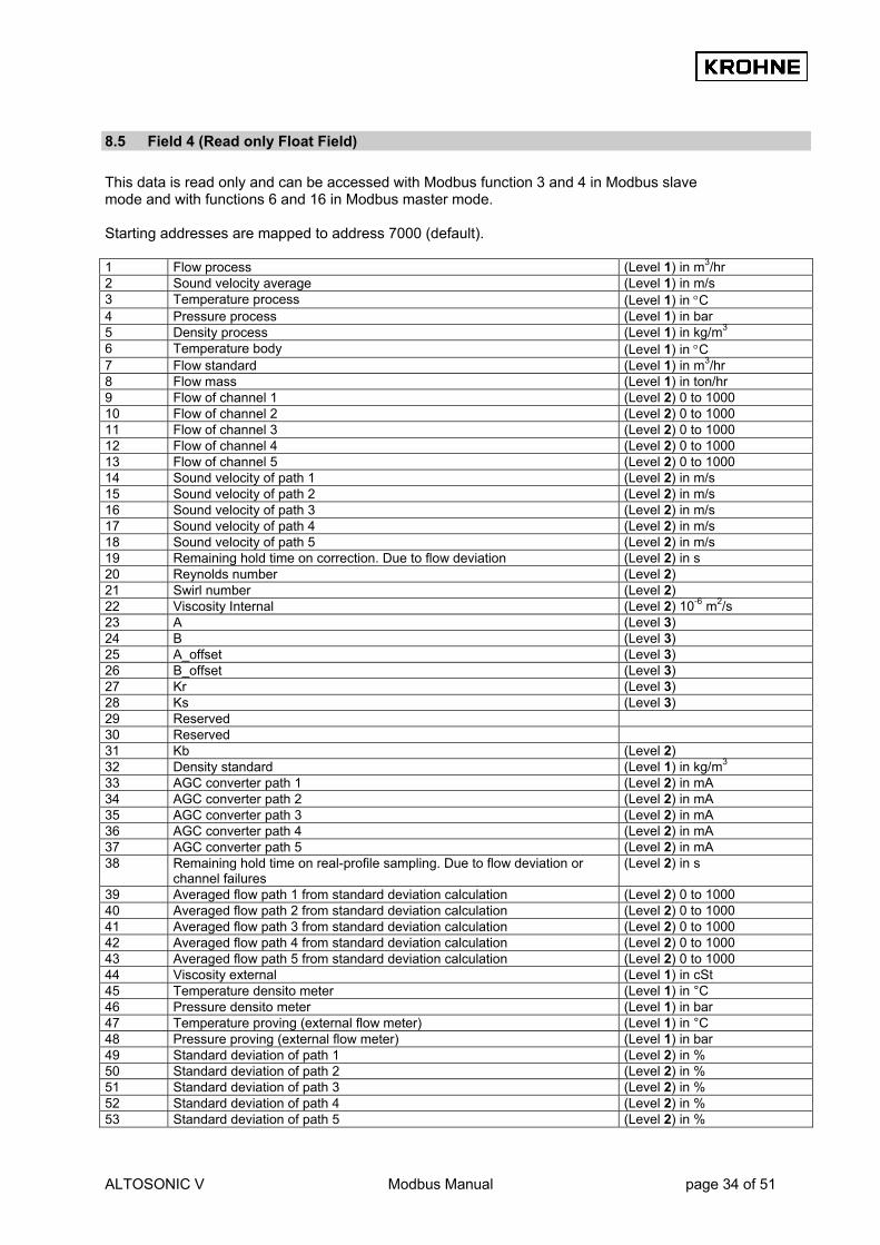
8.5 Field 4 (Read only Float Field) This data is read only and can be accessed with Modbus function 3 and 4 in Modbus slave mode and with functions 6 and 16 in Modbus master mode. Starting addresses are mapped to address 7000 (default). 1 Flow process (Level 1) in m3/hr 2 Sound velocity average (Level 1) in m/s 3 Temperature process (Level 1) in °C 4 Pressure process (Level 1) in bar 5 Density process (Level 1) in kg/m3 6 Temperature body (Level 1) in °C 7 Flow standard (Level 1) in m3/hr 8 Flow mass (Level 1) in ton/hr 9 Flow of channel 1 (Level 2) 0 to 1000 10 Flow of channel 2 (Level 2) 0 to 1000 11 Flow of channel 3 (Level 2) 0 to 1000 12 Flow of channel 4 (Level 2) 0 to 1000 13 Flow of channel 5 (Level 2) 0 to 1000 14 Sound velocity of path 1 (Level 2) in m/s 15 Sound velocity of path 2 (Level 2) in m/s 16 Sound velocity of path 3 (Level 2) in m/s 17 Sound velocity of path 4 (Level 2) in m/s 18 Sound velocity of path 5 (Level 2) in m/s 19 Remaining hold time on correction. Due to flow deviation (Level 2) in s 20 Reynolds number (Level 2) 21 Swirl number (Level 2) 22 Viscosity Internal (Level 2) 10-6 m2/s 23 A (Level 3) 24 B (Level 3) 25 A_offset (Level 3) 26 B_offset (Level 3) 27 Kr (Level 3) 28 Ks (Level 3) 29 Reserved 30 Reserved 31 Kb (Level 2) 32 Density standard (Level 1) in kg/m3 33 AGC converter path 1 (Level 2) in mA 34 AGC converter path 2 (Level 2) in mA 35 AGC converter path 3 (Level 2) in mA 36 AGC converter path 4 (Level 2) in mA 37 AGC converter path 5 (Level 2) in mA 38 Remaining hold time on real-profile sampling. Due to flow deviation or
channel failures (Level 2) in s
39 Averaged flow path 1 from standard deviation calculation (Level 2) 0 to 1000 40 Averaged flow path 2 from standard deviation calculation (Level 2) 0 to 1000 41 Averaged flow path 3 from standard deviation calculation (Level 2) 0 to 1000 42 Averaged flow path 4 from standard deviation calculation (Level 2) 0 to 1000 43 Averaged flow path 5 from standard deviation calculation (Level 2) 0 to 1000 44 Viscosity external (Level 1) in cSt 45 Temperature densito meter (Level 1) in °C 46 Pressure densito meter (Level 1) in bar 47 Temperature proving (external flow meter) (Level 1) in °C 48 Pressure proving (external flow meter) (Level 1) in bar 49 Standard deviation of path 1 (Level 2) in % 50 Standard deviation of path 2 (Level 2) in % 51 Standard deviation of path 3 (Level 2) in % 52 Standard deviation of path 4 (Level 2) in % 53 Standard deviation of path 5 (Level 2) in %
ALTOSONIC V Modbus Manual page 35 of 51
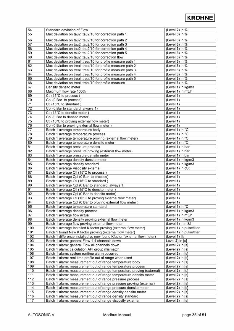
54 Standard deviation of Flow (Level 2) in % 55 Max deviation on tau2::tau2/10 for correction path 1 (Level 3) in %
56 Max deviation on tau2::tau2/10 for correction path 2 (Level 3) in % 57 Max deviation on tau2::tau2/10 for correction path 3 (Level 3) in % 58 Max deviation on tau2::tau2/10 for correction path 4 (Level 3) in % 59 Max deviation on tau2::tau2/10 for correction path 5 (Level 3) in % 60 Max deviation on tau2::tau2/10 for correction flow (Level 3) in % 61 Max deviation on treal::treal/10 for profile measure path 1 (Level 3) in % 62 Max deviation on treal::treal/10 for profile measure path 2 (Level 3) in % 63 Max deviation on treal::treal/10 for profile measure path 3 (Level 3) in % 64 Max deviation on treal::treal/10 for profile measure path 4 (Level 3) in % 65 Max deviation on treal::treal/10 for profile measure path 5 (Level 3) in % 66 Max deviation on treal::treal/10 for profile measure (Level 3) in % 67 Density densito meter (Level 1) in kg/m3 68 Maximum flow rate 100% (Level 1) in m3/h 69 Ctl (15°C to process ) (Level 1) 70 Cpl (0 Bar to process) (Level 1) 71 Ctl (15°C to standard ) (Level 1) 72 Cpl (0 Bar to standard, always 1) (Level 1) 73 Ctl (15°C to densito meter ) (Level 1) 74 Cpl (0 Bar to densito meter) (Level 1) 75 Ctl (15°C to proving external flow meter) (Level 1) 76 Cpl (0 Bar to proving external flow meter ) (Level 1) 77 Batch 1 average temperature body (Level 1) in °C 78 Batch 1 average temperature process (Level 1) in °C 79 Batch 1 average temperature proving (external flow meter) (Level 1) in °C 80 Batch 1 average temperature densito meter (Level 1) in °C 81 Batch 1 average pressure process (Level 1) in bar 82 Batch 1 average pressure proving (external flow meter) (Level 1) in bar 83 Batch 1 average pressure densito meter (Level 1) in bar 84 Batch 1 average density densito meter (Level 1) in kg/m3 85 Batch 1 average density standard (Level 1) in kg/m3 86 Batch 1 average Viscosity external (Level 1) in cSt 87 Batch 1 average Ctl (15°C to process ) (Level 1) 88 Batch 1 average Cpl (0 Bar to process) (Level 1) 89 Batch 1 average Ctl (15°C to standard ) (Level 1) 90 Batch 1 average Cpl (0 Bar to standard, always 1) (Level 1) 91 Batch 1 average Ctl (15°C to densito meter ) (Level 1) 92 Batch 1 average Cpl (0 Bar to densito meter) (Level 1) 93 Batch 1 average Ctl (15°C to proving external flow meter) (Level 1) 94 Batch 1 average Cpl (0 Bar to proving external flow meter ) (Level 1) 95 Batch 1 average temperature standard (Level 1) in °C 96 Batch 1 average density process (Level 1) in kg/m3 97 Batch 1 average flow actual (Level 1) in m3/h 98 Batch 1 average density proving external flow meter (Level 1) in kg/m3 99 Batch 1 average flow proving external flow meter (Level 1) in m3/h 100 Batch 1 average Installed K factor proving (external flow meter) (Level 1) in pulse/liter 101 Batch 1 found New K factor proving (external flow meter) (Level 1) in pulse/liter 102 Batch 1 difference installed vs new found Kfactor (external flow meter) (Level 1) % 103 Batch 1 alarm: general Flow 1-4 channels down Level 2) in [s] 104 Batch 1 alarm: general Flow all channels down (Level 2) in [s] 105 Batch 1 alarm: calculation API group mismatch (Level 2) in [s] 106 Batch 1 alarm: system runtime alarm occurred (Level 2) in [s] 107 Batch 1 alarm: real time profile out of range when used (Level 2) in [s] 108 Batch 1 alarm: measurement out of range temperature body (Level 2) in [s] 109 Batch 1 alarm: measurement out of range temperature process (Level 2) in [s] 110 Batch 1 alarm: measurement out of range temperature proving (external) (Level 2) in [s] 111 Batch 1 alarm: measurement out of range temperature densito meter (Level 2) in [s] 112 Batch 1 alarm: measurement out of range pressure process (Level 2) in [s] 113 Batch 1 alarm: measurement out of range pressure proving (external) (Level 2) in [s] 114 Batch 1 alarm: measurement out of range pressure densito meter (Level 2) in [s] 115 Batch 1 alarm: measurement out of range density densito meter (Level 2) in [s] 116 Batch 1 alarm: measurement out of range density standard (Level 2) in [s] 117 Batch 1 alarm: measurement out of range viscosity external (Level 2) in [s]

ALTOSONIC V Modbus Manual page 36 of 51
118 Batch 1 alarm: override applied temperature body (Level 2) in [s] 119 Batch 1 alarm: override applied temperature process (Level 2) in [s] 120 Batch 1 alarm: override applied temperature proving (external flow meter) (Level 2) in [s] 121 Batch 1 alarm: override applied temperature densito meter (Level 2) in [s] 122 Batch 1 alarm: override applied pressure process (Level 2) in [s] 123 Batch 1 alarm: override applied pressure proving (external flow meter) (Level 2) in [s] 124 Batch 1 alarm: override applied pressure densito meter (Level 2) in [s] 125 Batch 1 alarm: override applied density densito meter (Level 2) in [s] 126 Batch 1 alarm: override applied density standard (Level 2) in [s] 127 Batch 1 alarm: override applied viscosity external (Level 2) in [s] 128 Batch 2 average temperature body (Level 1) in °C 129 Batch 2 average temperature process (Level 1) in °C 130 Batch 2 average temperature proving (external flow meter) (Level 1) in °C 131. Batch 2 average temperature densito meter (Level 1) in °C 132. Batch 2 average pressure process (Level 1) in bar 133. Batch 2 average pressure proving (external flow meter) (Level 1) in bar 134. Batch 2 average pressure densito meter (Level 1) in bar 135. Batch 2 average density densito meter (Level 1) in kg/m3 136 Batch 2 average density standard (Level 1) in kg/m3 137 Batch 2 average Viscosity external (Level 1) in cSt 138 Batch 2 average Ctl (15°C to process ) (Level 1) 139 Batch 2 average Cpl (0 Bar to process) (Level 1) 140 Batch 2 average Ctl (15°C to standard ) (Level 1) 141 Batch 2 average Cpl (0 Bar to standard, always 1) (Level 1) 142 Batch 2 average Ctl (15°C to densito meter ) (Level 1) 143 Batch 2 average Cpl (0 Bar to densito meter) (Level 1) 144 Batch 2 average Ctl (15°C to proving external flow meter) (Level 1) 145 Batch 2 average Cpl (0 Bar to proving external flow meter ) (Level 1) 146 Batch 2 average temperature standard (Level 1) in °C 147 Batch 2 average density process (Level 1) in kg/m3 148 Batch 2 average flow actual (Level 1) in m3/h 149 Batch 2 average density proving external flow meter (Level 1) in kg/m3 150 Batch 2 average flow proving external flow meter (Level 1) in m3/h 151 Batch 2 average Installed K factor proving (external flow meter) (Level 1) in pulse/liter 152 Batch 2 found New K factor proving (external flow meter) (Level 1) in pulse/liter 153 Batch 2 difference installed vs new found Kfactor (external flow meter) (Level 1) % 154 Batch 2 alarm: general Flow 1-4 channels down Level 2) in [s] 155 Batch 2 alarm: general Flow all channels down (Level 2) in [s] 156. Batch 2 alarm: calculation API group mismatch (Level 2) in [s] 157 Batch 2 alarm: system runtime alarm occurred (Level 2) in [s] 158 Batch 2 alarm: real time profile out of range when used (Level 2) in [s] 159 Batch 2 alarm: measurement out of range temperature body (Level 2) in [s] 160 Batch 2 alarm: measurement out of range temperature process (Level 2) in [s] 161 Batch 2 alarm: measurement out of range temperature proving (external) (Level 2) in [s] 162 Batch 2 alarm: measurement out of range temperature densito meter (Level 2) in [s] 163 Batch 2 alarm: measurement out of range pressure process (Level 2) in [s] 164 Batch 2 alarm: measurement out of range pressure proving (external) (Level 2) in [s] 165 Batch 2 alarm: measurement out of range pressure densito meter (Level 2) in [s] 166 Batch 2 alarm: measurement out of range density densito meter (Level 2) in [s] 167 Batch 2 alarm: measurement out of range density standard (Level 2) in [s] 168 Batch 2 alarm: measurement out of range viscosity external (Level 2) in [s] 169 Batch 2 alarm: override applied temperature body (Level 2) in [s] 170 Batch 2 alarm: override applied temperature process (Level 2) in [s] 171 Batch 2 alarm: override applied temperature proving (external flow meter) (Level 2) in [s] 172 Batch 2 alarm: override applied temperature densito meter (Level 2) in [s] 173 Batch 2 alarm: override applied pressure process (Level 2) in [s] 174 Batch 2 alarm: override applied pressure proving (external flow meter) (Level 2) in [s] 175 Batch 2 alarm: override applied pressure densito meter (Level 2) in [s] 176 Batch 2 alarm: override applied density densito meter (Level 2) in [s] 177 Batch 2 alarm: override applied density standard (Level 2) in [s] 178 Batch 2 alarm: override applied viscosity external (Level 2) in [s] 179 Service value: temperature body (Level 2) in °C 180 Service value: temperature process (Level 2) in °C 181 Service value: temperature proving (external flow meter) (Level 2) in °C

ALTOSONIC V Modbus Manual page 37 of 51
182 Service value: temperature densito meter (Level 2) in °C 183 Service value: pressure process (Level 2) in Bar 184 Service value: pressure proving (external flow meter) (Level 2) in Bar 185 Service value: pressure densito meter (Level 2) in Bar 186 Service value: density densito meter (Level 2) in kg/m3 187 Service value: density standard (Level 2) in kg/m3 188 Service value: viscosity external (Level 2) in cSt 189 Flow profile in channel 1 (indication) (Level 1) in m/s 190 Flow profile in channel 2 (indication) (Level 1) in m/s 191 Flow profile in channel 3 (indication) (Level 1) in m/s 192 Flow profile in channel 4 (indication) (Level 1) in m/s 193 Flow profile in channel 5 (indication) (Level 1) in m/s 194..213 Krohne use only 214…220 Reserved
8.6 Field 5 (Read only Double Field) This data is read only and can be accessed with Modbus function 3 and 4 in Modbus slave mode and with functions 6 and 16 in Modbus master mode. Starting addresses are mapped to address 6000 (default). 1 Resetable totaliser: process sum (Level 1) in Liters 2 Flow process (Level 1) in m3/hr 3 Sound velocity average (Level 1) in m/s 4 Resetable totaliser: standard sum (Level 1) in Liters 5 Flow standard (Level 1) in m3/hr 6 Resetable totaliser: mass sum (Level 1) in kg 7 Flow mass (Level 1) in Ton/hr 8 Reserved (Level 1) 9 Resetable totaliser: process forward (Level 1) in Liters 10 Resetable totaliser: process reverse (Level 1) in Liters 11 Resetable totaliser: standard forward (Level 1) in Liters 12 Resetable totaliser: standard reverse (Level 1) in Liters 13 Resetable totaliser: mass forward (Level 1) in kg 14 Resetable totaliser: mass reverse (Level 1) in kg 15 Resetable totaliser: external flow meter process (Level 1) in Liters 16 Resetable totaliser: external flow meter standard (Level 1) in Liters 17 Resetable totaliser: external flow meter mass (Level 1) in kg 18 Non resetable totaliser: process sum (Level 1) Value in m3 19 Non resetable totaliser: process forward (Level 1) Value in m3 20 Non resetable totaliser: process reverse (Level 1) Value in m3 21 Non resetable totaliser: standard sum (Level 1) Value in m3 22 Non resetable totaliser: standard forward (Level 1) Value in m3 23 Non resetable totaliser: standard reverse (Level 1) Value in m3 24 Non resetable totaliser: mass sum (Level 1) Value in ton 25 Non resetable totaliser: mass forward (Level 1) Value in ton 26 Non resetable totaliser: mass reverse (Level 1) Value in ton 27…33 Reserved

ALTOSONIC V Modbus Manual page 38 of 51
8.7 Field 6 (Read/Write Float Field) In slave mode write to field by function 16, read from field by function 3. In Master mode write to field by function 3, read from field by function 16 Starting addresses are mapped to address 7500 (default). NOTE that for explanation on how to handle writing to these parameters: see chapters 7.6 How data is written to the float field 8.8 Explanation of Data Available to Modbus 1 API: time to update a parameter (read only) (Level 1) in sec, max 30 sec 2 API: correction type (Level 4) 0,1,2 3 API: density standard type (Level 4) 0,1,2 4 API: fluid type (Level 4) 0,1,2,3,4,5 5 API: stand. Density crude (fluid type 0) (Level 4) 610.5..1075.0 kg/m3 6 API: stand. Density gasoline (fluid type 1) (Level 4) 653.0.. 770.0 kg/m3 7 API: stand. Density trans.area(fluid type 2) (Level 4) 770.5.. 787.5 kg/m3 8 API: stand. Density jet group (fluid type 3) (Level 4) 788.0.. 838.5 kg/m3 9 API: stand. Density fuel oil (fluid type 4) (Level 4) 839.0..1075.0 kg/m3 10 API: stand. Density free fill (fluid type 5) (Level 4) 500.0..2000.0 kg/m3 11 API: free fill K0 (Level 4) –10e9 .. 10e9 12 API: free fill K1 (Level 4) –10e9 .. 10e9 13 API: free fill K2 (Level 4) –10e9 .. 10e9 14 API: temperature standard (Level 4) 0-30°C 15...20 Reserved 21 EXT: time to update a parameter (read only) (Level 1) in sec, max 30 sec 22 EXT: external K factor (Level 4) in pulse/liter 23 EXT/API: parameters changeable under flowing condition or beneath low-
flow cut-off (Level 4) 0=always 1=only < low flow cut-off
24...29 Reserved 30 UFP batch control:
Normal: Setup=9 (if UFP batch1 status batch=0 is no batch) Cancel=5 (if UFP batch1 status batch=1 is set-up) Start batch=119 (if UFP batch1 status batch=1 is set-up) End batch=229 (if UFP batch1 status batch=1 is running) reset printing=1009 (if UFP batch1 status batch=5…10 is printing) Confirm ticket=779 (if UFP batch1 status batch=10 is confirm) Continuous pipe line measurement, ticket on demand: End with no reset values=559 (if UFP batch1 status batch is not printing) End with reset values=229 (if UFP batch1 status batch is not printing) Reset printing=1009 (if UFP batch1 status batch 5…10 is printing) 559 and 229 have automatic freeze of batch values (on Modbus) for a maximum of 30 seconds (see also Boolean 2075)
(Level 4) On command value input: Return 0 if not accepted Return 1 if accepted Reset to -99999 after 5 seconds
31 Solartron1: time to update a parameter (read only) (Level 1) in sec, max 30 sec 32 Solartron1: K0 (Level 4) calib. Parameter 33 Solartron1: K1 (Level 4) calib. Parameter 34 Solartron1: K2 (Level 4) calib. Parameter 35 Solartron1: K18 (Level 4) calib. Parameter 36 Solartron1: K19 (Level 4) calib. Parameter 37 Solartron1: K20A (Level 4) calib. Parameter 38 Solartron1: K20B (Level 4) calib. Parameter 39 Solartron1: K21A (Level 4) calib. Parameter 40 Solartron1: K21B (Level 4) calib. Parameter 41 Solartron2: Time to update a parameter (read only) (Level 1) in sec, max 30 sec 42 Solartron2: K0 (Level 4) calib. Parameter 43 Solartron2: K1 (Level 4) calib. Parameter 44 Solartron2: K2 (Level 4) calib. Parameter 45 Solartron2: K18 (Level 4) calib. Parameter

ALTOSONIC V Modbus Manual page 39 of 51
46 Solartron2: K19 (Level 4) calib. Parameter 47 Solartron2: K20A (Level 4) calib. Parameter 48 Solartron2: K20B (Level 4) calib. Parameter 49 Solartron2: K21A (Level 4) calib. Parameter 50 Solartron2: K21B (Level 4) calib. Parameter 51 Sarasota1: Time to update a parameter (read only) (Level 1) in sec, max 30 sec 52 Sarasota1: K (Level 4) calib. Parameter 53 Sarasota1: T0 (Level 4) calib. Parameter 54 Sarasota1: D0 (Level 4) calib. Parameter 55 Sarasota1: Nt (Level 4) calib. Parameter 56 Sarasota1: Np (Level 4) calib. Parameter 57 Sarasota1: Tcal (Level 4) calib. Parameter 58 Sarasota1: Pcal (Level 4) calib. Parameter 59 Sarasota2: Time to update a parameter (read only) (Level 1) in sec, max 30 sec 60 Sarasota2: K (Level 4) calib. Parameter 61 Sarasota2: T0 (Level 4) calib. Parameter 62 Sarasota2: D0 (Level 4) calib. Parameter 63 Sarasota2: Nt (Level 4) calib. Parameter 64 Sarasota2: Np (Level 4) calib. Parameter 65 Sarasota2: Tcal (Level 4) calib. Parameter 66 Sarasota2: Pcal (Level 4) calib. Parameter 67 Input in UFP (if enabled in UFP): temperature body (Level 4) in °C 68 Input in UFP (if enabled in UFP): temperature process (Level 4) in °C 69 Input in UFP (if enabled in UFP): temperature proving, external flow meter (Level 4) in °C 70 Input in UFP (if enabled in UFP): temperature densito meter (Level 4) in °C 71 Input in UFP (if enabled in UFP): pressure process (Level 4) in Bar 72 Input in UFP (if enabled in UFP): pressure proving, external flow meter (Level 4) in Bar 73 Input in UFP (if enabled in UFP): pressure densito meter (Level 4) in Bar 74 Input in UFP (if enabled in UFP): density densito meter (Level 4) in kg/m3 75 Input in UFP (if enabled in UFP): density standard (Level 4) in kg/m3 76 Input in UFP (if enabled in UFP): viscosity dynamic (Level 4) in cSt 77 System time UFP adjust in seconds
See Boolean 2230 to enable write (Level 4) in sec, -7200…7200 seconds
78 OVERRIDE : time to update a parameter (read only) (Level 1) in sec, max 30 sec 79 OVERRIDE if set is enabled: temperature body (Level 4) in °C 80 OVERRIDE if set is enabled: temperature process to override (Level 4) in °C 81 OVERRIDE if set is enabled: temperature proving to override (Level 4) in °C 82 OVERRIDE if set is enabled: temperature densito meter to override (Level 4) in °C 83 OVERRIDE if set is enabled: pressure process to override (Level 4) in Bar 84 OVERRIDE if set is enabled: pressure proving to override (Level 4) in Bar 85 OVERRIDE if set is enabled: pressure densito meter to override (Level 4) in Bar 86 OVERRIDE if set is enabled: density densito meter to override (Level 4) in kg/m3 87 OVERRIDE if set is enabled: density standard to override (Level 4) in kg/m3 88 OVERRIDE if set is enabled: viscosity external to override (Level 4) in cSt 89 Batch reference number for internal batch ticket
Possible to enter during the batch (in case of a program stop number is set to 0. After batch stop, the number is reset to 0.
(Level 4)
90 Krohne use only 91..105 Reserved

ALTOSONIC V Modbus Manual page 40 of 51
8.8 Explanation of Data Available to Modbus Basic Flow measurement WARNING This warning occurs if 1…4 paths fail, but the system works within specifications. Possible sources of the warning are over range, path failure, deviation in sound velocity or communication failure.
Basic Flow measurement ERROR This error occurs if all paths fail. Possible sources of the error are over range, path failure, deviation in sound velocity, communication failure System Runtime WARNING This warning is caused by system failures or failures from the Modbus driver. See system messages These failures will not influence the flow measurement. The last warning number is saved into the integer and long integer field System Runtime warning/error number… System Runtime ERROR This error is caused by system failures. See system messages These failures might influence the flow measurement. The last error number is saved into the integer and long integer field System Runtime warning/error number. System Set-up WARNING This error is caused by insufficient statistical data during set-up. Default data is used until enough statistical information is recorded (under normal conditions). In this case the warning is self-resolving. Another possibility is an improper initialisation of the Modbus driver (Modbus will not be accessible). In this case, the warning remains active. The integer and long integer System Set-up warning/error number contains the error number.
See the ALTOSONIC-V Operating Manual System Set-up ERROR This error is caused by an improper initialisation. The Modbus driver may be initialised successfully. The integer and long integer System Set-up warning/error number contains the error number.
See the ALTOSONIC-V Operating Manual Resetable totaliser Rollover occurred Status for if the totaliser exceeds the value of 1E9 liter, the totaliser is decreased with 1E9 and the totaliser Rollover occurred Boolean is set. Resetable totaliser Reset occurred Status for if the totaliser has been reset (by Modbus, manually, or relay contact). Flow direction Status for the current flow direction: 0=forward direction, and 1=reverse direction. Algo. Basic flow on output Status for calculation with the basic algorithm. Algo. Reyn. Correction on output Status for calculation with the basic algorithm, including Reynolds correction algorithm. Swirl correction on output Status for calculation with the basic algorithm, including Swirl correction algorithm. Temperature correction on output Status for correction for tube expansion caused by temperature deviation.

ALTOSONIC V Modbus Manual page 41 of 51
Standard volume on output Status for the corrected/calculated standard conditions of 15 °C and 1 Bar. Correction parameters HOLD. Due to flow deviation In case of large flow deviation the correction parameters are ‘frozen’ until enough statistical information is available to perform a reliable correction. Overrange data sensor 1…5 This Boolean exists for each ultrasonic channel. If the flow converter measuring the flow is out of range (±125%) this Boolean is set. Path failure sensor 1…5 This Boolean exists for each ultrasonic channel. If the flow converter detects an ultrasonic path failure, this Boolean is set. Path failure is mostly due to gas, but might be caused by an obstructive solid particle. Deviation in sound velocity sensor 1…5 This Boolean exists for each ultrasonic channel. The measurement program calculates the mean sound velocity out of the three most nearby values and checks all channels on their deviation to this mean value. If the deviation is too large this Boolean is set. Communication failure sensor 1…5 This Boolean exists for each ultrasonic channel. The data transfer with the flow converter is tested with a data validation check, if this test is negative this Boolean is set. Real profile sampling on hold Warning that Real Profile Sampling is on hold due to channel failure (1..5), extreme flow deviations or low flow. External Viscosity meter, Temperature external densito meter, Pressure external densito meter, Temperature external flow meter, Pressure external flow meter out of range Warning that the specific reading is out of limits (set for low and high alarm). Acknowledge_flags_field_0
See chapter 7.5 for more information on this Boolean. General_acknowledge_flags_field_0
See chapter 7.5 to for more information on this Boolean. Reset All errors This Boolean can be set to reset/update all errors, occurred under runtime condition. This Boolean is self-resetting. Reset Totalisers and All Errors This Boolean can be set to reset all the totalisers AND to reset/update all errors AND process time, occurred under runtime condition. (Action is performed if Boolean is set to 1). This Boolean is self-resetting. Flow actual /Flow standard / Flow mass Value for the flow available as scaled integer, scaled long integer, float and double. The floating-point numbers represent the flow in m3/hr or kg/m3, the scaled integers are scaled to the full-scale value (-32768 … +32767 -125%… +125%). Sound velocity Value for the sound velocity, available as scaled integer, scaled long integer, float and double.

ALTOSONIC V Modbus Manual page 42 of 51
The floating-point numbers represent the sound velocity in m/s, the scaled integers are scaled to 32767 (scaled 0...32767 0...3276.7 m/s). Flow of path 1…5 Available as scaled integer and float, these values represent internal UFP-V units. Sound velocity of path 1...5 Available as scaled integer and float. The floating-point numbers represent the sound velocity in m/s, the scaled integers are scaled to 32767 (scaled 0…32767 0...3276.7 m/s). System Set-up warning/error number This value contains the number of the last occurred system set-up warning or system set-up error. System Runtime warning/error number This value contains the number of the last occurred system runtime warning or system runtime error. System messages 1…64 Each system message corresponds to a bit in this integer value. If a system message occurs, the accompanying bit is set, the bit remains set until the Reset_All_Errors Boolean is set. The messages are numbered from the least significant bit to the most significant bit. Integer values contains the occurred-status of 16 messages, Long integers contain the occurred-status of 32 messages, Process/standard/mass Totaliser Sum of forward and reverse for the process/standard/mass totalisers, available as long integer and double. All data types represents the totaliser in Liters (volumes) or (mass) kg, the totalisers have a rollover at 1E9. Is resetable. Forward process/standard/mass Totaliser Values for the forward totalisers, available as long integer and double. All data types represents the forward totalisers in Liters(volumes) or (mass) kg, the totalisers have a rollover at 1E9. Is resetable. Reverse process/standard/mass Totaliser Values for the reverse totalisers, available as long integer and double. All data types represents the forward totalisers in Liters(volumes) or kg(mass), the totalisers have a rollover at 1E9. Is resetable. Remaining HOLD time on real-profile sampling In case of large flow deviation or low flow, the real-profile sampling is on hold until the flow has stabilised. Until then no new real-profile is sampled API: Time to update a parameter (read only) Time remaining to update a float in the API application field. Starts at 20 seconds remaining time after the Boolean 2201 API enable writing data and counting down to 0 seconds. When at 0 seconds the Boolean 2201 will reset (0) and it is not possible to write to the application field. API: Correction type The type of correction to calculate the standard volume and/or mass. 0: Disable, no standard volume or mass will be calculated. 1: Standard volume/mass by API 2540 2: Mass measurement by process density (measured by densito meter)
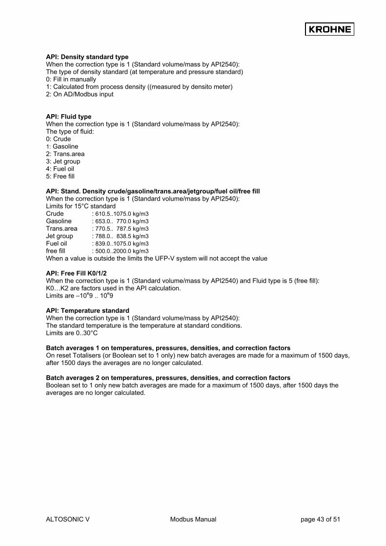
ALTOSONIC V Modbus Manual page 43 of 51
API: Density standard type When the correction type is 1 (Standard volume/mass by API2540): The type of density standard (at temperature and pressure standard) 0: Fill in manually 1: Calculated from process density ((measured by densito meter) 2: On AD/Modbus input API: Fluid type When the correction type is 1 (Standard volume/mass by API2540): The type of fluid: 0: Crude 1: Gasoline 2: Trans.area 3: Jet group 4: Fuel oil 5: Free fill API: Stand. Density crude/gasoline/trans.area/jetgroup/fuel oil/free fill When the correction type is 1 (Standard volume/mass by API2540): Limits for 15°C standard Crude : 610.5..1075.0 kg/m3 Gasoline : 653.0.. 770.0 kg/m3 Trans.area : 770.5.. 787.5 kg/m3 Jet group : 788.0.. 838.5 kg/m3 Fuel oil : 839.0..1075.0 kg/m3 free fill : 500.0..2000.0 kg/m3 When a value is outside the limits the UFP-V system will not accept the value API: Free Fill K0/1/2 When the correction type is 1 (Standard volume/mass by API2540) and Fluid type is 5 (free fill): K0…K2 are factors used in the API calculation. Limits are –10e9 .. 10e9 API: Temperature standard When the correction type is 1 (Standard volume/mass by API2540): The standard temperature is the temperature at standard conditions. Limits are 0..30°C Batch averages 1 on temperatures, pressures, densities, and correction factors On reset Totalisers (or Boolean set to 1 only) new batch averages are made for a maximum of 1500 days, after 1500 days the averages are no longer calculated. Batch averages 2 on temperatures, pressures, densities, and correction factors Boolean set to 1 only new batch averages are made for a maximum of 1500 days, after 1500 days the averages are no longer calculated.

ALTOSONIC V Modbus Manual page 44 of 51
8.9 The System Messages
The system messages contains the system runtime warnings and alarms. They are stored as bits into the integer data. Each system message is packed as one message per bit of the integer. The message is active if the accompanying bit is one. The messages are numbered from the least significant bit to the most significant bit. The status of the system is divided into: • System Runtime Warnings. These are caused by system failures. These failures will not influence the
flow measurement. • System Runtime Alarms. These are caused by system failures. These failures might influence the flow
measurement. Identified System Runtime Errors are numbered 1 to 60 are:
Identified System Runtime Errors are numbered 1 to 60, A = alarm, W = warning: Error no. In function Problem Consequence A : 1 Get RS485 data from
converters Overrun, missed data Missed data, message
A : 2 Self test Error in self-test Non-reliable memory A : 3 Batch start / stop Error during saving files of start or stop File lost but ticket is made A : 4 Profile correction (REAL) Error in state_correction Attempt divide to by zero W: 5 Read Backup all files Error in reading backup file Possible loss of backup file W: 6 Switching disk Error in finding a drive Message W: 7 System time A notice that the system time was adjusted
manually or by Modbus. No consequence for totalisers or process time, only on ticket time
W: 8 End of a calibration Error write in calibration report File lost, message A: 9 Batch status backup Status file corrupt Possible loss of batch status W: 10 Override values files Error in opening/closing override value file Override values not stored but
still in use A: 11 Batch totaliser backup Totaliser backup-file corrupt File lost , message A: 12 Batch average backup Average backup-file corrupt File lost, message A: 13 Batch ticket create Error in creating batch ticket file Ticket itself is made for printing
but lost during saving W: 14 Opening file (for update) Error in opening REAL file File lost, message W: 15 Closing file (for update) Error in closing REAL file File lost, message W: 16 API settings Error in file, defaults are loaded and saved Old settings lost W: 17 Batch 2 A alarm on batch 2 file (Batch 2 is only
used through Modbus with a Scada system) File lost, message
W: 18 Check free disk-space Error dos_getdiskfree() call Time-out function 30 s W: 19 Check free disk-space Low on disk-space Time-out function 30 s W: 20 Ad card overrun The requested AD card is not noticed Solve the problem W: 21 Opening file (for update) Error opening API table file File lost, message W: 22 Value check 1 or more API values defaulted Check the installed parameters W: 23 Opening file (for update) Error opening external flow meter file File lost, message W: 24 Value check Default external flow meter K-factor Check the installed K-factor W: 25 Counter input Unable to read Counter value Read on next entry A : 26 Calibration MP103 card MPCA File corrupt Install backup A : 27 Calibration AD card File corrupt Install backup A : 28 Calibration data Densito
Cells File corrupt Automatic install of default values
Set the correct values on-line A : 29 Batch ticket currently
saved A Requested batch ticket not available for printing
A ticket by that name was not saved or had a previous save error
A : 30 Batch ticket CRC error in a Batch ticket A ticket was not saved correctly or was changed manually
W: 31 Read batch ticket previously saved
A Requested batch ticket not available for printing
A ticket by that name was not saved or had a previous save error
W : 32 Batch ticket close file Error in closing a ticket file Ticket file not closed , probably because it could not be opened
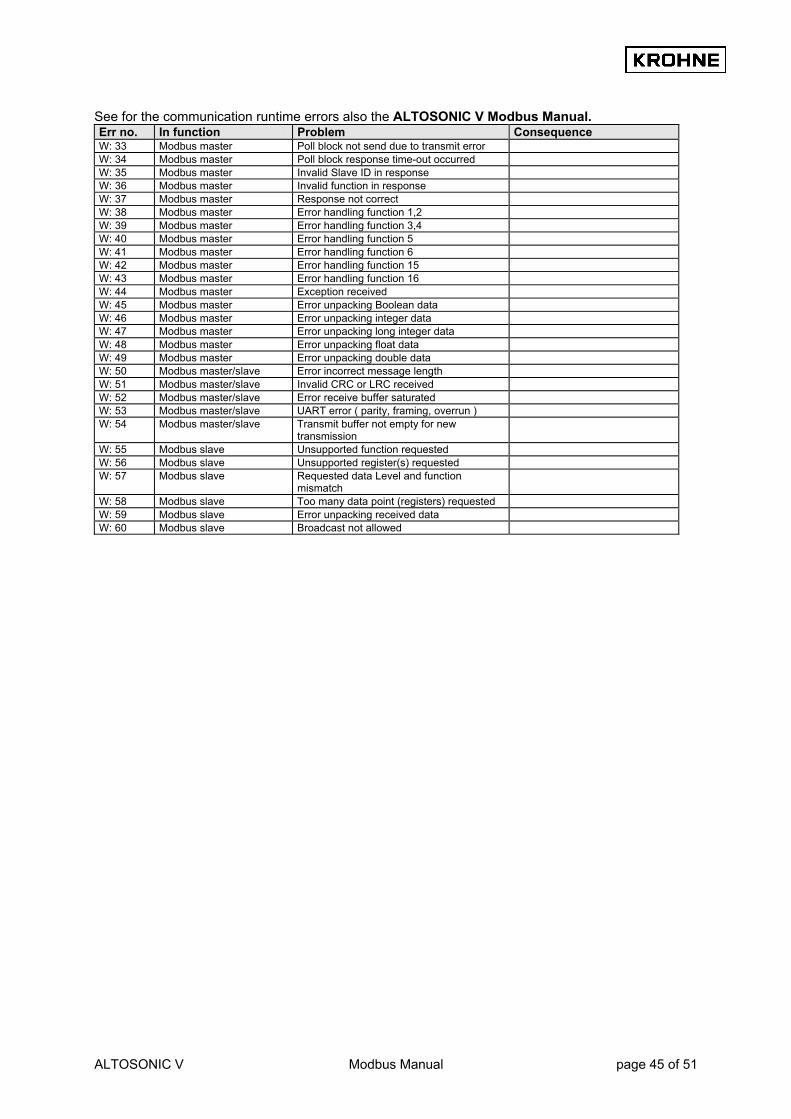
ALTOSONIC V Modbus Manual page 45 of 51
See for the communication runtime errors also the ALTOSONIC V Modbus Manual. Err no. In function Problem Consequence W: 33 Modbus master Poll block not send due to transmit error W: 34 Modbus master Poll block response time-out occurred W: 35 Modbus master Invalid Slave ID in response W: 36 Modbus master Invalid function in response W: 37 Modbus master Response not correct W: 38 Modbus master Error handling function 1,2 W: 39 Modbus master Error handling function 3,4 W: 40 Modbus master Error handling function 5 W: 41 Modbus master Error handling function 6 W: 42 Modbus master Error handling function 15 W: 43 Modbus master Error handling function 16 W: 44 Modbus master Exception received W: 45 Modbus master Error unpacking Boolean data W: 46 Modbus master Error unpacking integer data W: 47 Modbus master Error unpacking long integer data W: 48 Modbus master Error unpacking float data W: 49 Modbus master Error unpacking double data W: 50 Modbus master/slave Error incorrect message length W: 51 Modbus master/slave Invalid CRC or LRC received W: 52 Modbus master/slave Error receive buffer saturated W: 53 Modbus master/slave UART error ( parity, framing, overrun ) W: 54 Modbus master/slave Transmit buffer not empty for new
transmission
W: 55 Modbus slave Unsupported function requested W: 56 Modbus slave Unsupported register(s) requested W: 57 Modbus slave Requested data Level and function
mismatch
W: 58 Modbus slave Too many data point (registers) requested W: 59 Modbus slave Error unpacking received data W: 60 Modbus slave Broadcast not allowed

ALTOSONIC V Modbus Manual page 46 of 51
9 Appendices
9.1 Appendix A: Time out values The character length lies between 9 and 12 bits The UFP-V determines the time between two bytes to recognise a communication failure or the end of a message. UFP-V discriminates between a timeout between 2 bytes and a timeout after the last byte, which occurs at the end of a message. The time between two bytes is measured with a resolution of ±100 us. To detect the timeout state (end of message) a timer is incremented every millisecond. A received byte will reset the timer. Every millisecond the timer value will be checked for a timeout value, when it will exceed a defined value it will mark the last received byte as end of message. Notice that the serial communication is a asynchrony process with respect to the used timer interrupt, therefore a ‘jitter’ of 1 ms must be taken into account. Modbus defined timeout values for every baud rate with N number of bytes:
Baud rate
9 bit 10 bit 11 bit 12 bit
Timeout chars
3.5 4.0 3.5 4.0 3.5 4.0 3.5 4.0
1200 26.25 ms 30 ms 29.17 ms 33.34 ms 32.08 ms 36.67 ms 35.00 ms 40 ms 2400 13.16 ms 15 ms 14.58 ms 6.67 ms 16.04 ms 18.33 ms 17.50 ms 20 ms 4800 6.56 ms 7.5 ms 7.29 ms 8.33 ms 8.02 ms 9.17 ms 8.75 ms 10 ms 9600 3.28 ms 3.75 ms 3.65 ms 4.16 ms 4.01 ms 4.58 ms 4.38 ms 5 ms 19200 1.64 ms 1.88 ms 1.82 ms 2.08 ms 2.01 ms 2.29 ms 2.19 ms 2.5 ms
The maximum time to detect a timeout (end of message) used in UFP-V: Baud rate 9 10 11 12 1200 28…29 ms 31…32 ms 33…34 ms 36…37 ms 2400 14…15 ms 15…16 ms 16…17 ms 18…19 ms 4800 6…7 ms 7…8 ms 8…9 ms 9…10 ms 9600 3…4 ms 3…4 ms 4…5 ms 4…5 ms 19200 2…3 ms 2…3 ms 2…3 ms 2…3 ms
The maximum time between 2 characters in a message (GAP) used in UFP-V: Baud rate 9 10 11 12 1200 28.2 ms 31.3 ms 34.4 ms 37.5 ms 2400 14.1 ms 15.6 ms 17.2 ms 8.8 ms 4800 7.0 ms 7.8 ms 8.6 ms 9.4 ms 9600 3.5 ms 3.9 ms 4.3 ms 4.7 ms 19200 1.8 ms 1.95 ms 2.2 ms 2.4 ms

ALTOSONIC V Modbus Manual page 47 of 51
9.2 Appendix B: LRC Generation (As taken from the website: www.modicon.com/techpubs/crc7.html) The Longitudinal Redundancy Check (LRC) field is one byte, containing an eight-bit binary value. The LRC value is calculated by the transmitting device, which appends the LRC to the message. The receiving device recalculates an LRC during receipt of the message, and compares the calculated value to the actual value it received in the LRC field. If the two values are not equal, an error results. The LRC is calculated by adding together successive eight-bit bytes in the message, discarding any carries, then two's complementing the result. The LRC is an eight-bit field, therefore each new addition of a character that would result in a value higher than 255 decimal simply rolls over the field's value through zero. Because there is no ninth bit, the carry is discarded automatically. Generating an LRC Step 1 : Add all bytes in the message, excluding the starting colon and ending CRLF. Add them into an eight-bit field, so that carries will be discarded. Step 2 Subtract the final field value from FF hex (all 1's), to produce the ones-complement. Step 3 Add 1 to produce the two's-complement. Placing the LRC into the Message When the the eight-bit LRC (two ASCII characters) is transmitted in the message, the high order character will be transmitted first, followed by the low order character-e.g., if the LRC value is 61 hex (0110 0001):
Figure 8 LRC Character Sequence Example An example of a C language function performing LRC generation is shown below. The function takes two arguments: unsigned char *auchMsg ; A pointer to the message buffer containing binary data to be used for generating the LRC unsigned short usDataLen ; The quantity of bytes in the message buffer. The function returns the LRC as a type unsigned char. LRC Generation Function static unsigned char LRC(auchMsg, usDataLen) unsigned char *auchMsg ; /* message to calculate */ unsigned short usDataLen ; /* LRC upon quantity of */ /* bytes in message */ {
unsigned char uchLRC = 0 ; /* LRC char initialized */ while (usDataLen--) /* pass through message */ uchLRC += *auchMsg++ ; /* buffer add buffer byte*/ /* without carry */ return ((unsigned char)(-((char_uchLRC))) ; /* return twos complemen */ }
9.3 Appendix C: CRC generation (As taken from the website: www.modicon.com/techpubs/crc7.html) The Cyclical Redundancy Check (CRC) field is two bytes, containing a 16-bit binary value. The CRC value is calculated by the transmitting device, which appends the CRC to the message. The receiving device recalculates a CRC during receipt of the message, and compares the calculated value to the actual value it received in the CRC field. If the two values are not equal, an error results. The CRC is started by first preloading a 16-bit register to all 1's. Then a process begins of applying successive eight-bit bytes of the message to the current contents of the register. Only the eight bits of data

ALTOSONIC V Modbus Manual page 48 of 51
in each character are used for generating the CRC. Start and stop bits, and the parity bit, do not apply to the CRC. During generation of the CRC, each eight-bit character is exclusive ORed with the register contents. The result is shifted in the direction of the least significant bit (LSB), with a zero filled into the most significant bit (MSB) position. The LSB is extracted and examined. If the LSB was a 1, the register is then exclusive ORed with a preset, fixed value. If the LSB was a 0, no exclusive OR takes place. This process is repeated until eight shifts have been performed. After the last (eighth) shift, the next eight-bit character is exclusive ORed with the register's current value, and the process repeats for eight more shifts as described above. The final contents of the register, after all the characters of the message have been applied, is the CRC value. Generating a CRC Step 1 Load a 16-bit register with FFFF hex (all 1's). Call this the CRC register. Step 2 Exclusive OR the first eight-bit byte of the message with the low order byte of the 16-bit CRC register, putting the result in the CRC register. Step 3 Shift the CRC register one bit to the right (toward the LSB), zerofilling the MSB. Extract and examine the LSB. Step 4 If the LSB is 0, repeat Step 3 (another shift). If the LSB is 1, Exclusive OR the CRC register with the polynomial value A001 hex (1010 0000 0000 0001). Step 5 Repeat Steps 3 and 4 until eight shifts have been performed. When this is done, a complete eight-bit byte will have been processed. Step 6 Repeat Steps 2 ... 5 for the next eight-bit byte of the message. Continue doing this until all bytes have been processed. Result The final contents of the CRC register is the CRC value. Step 7 When the CRC is placed into the message, its upper and lower bytes must be swapped as described below. Placing the CRC into the Message When the 16-bit CRC (two eight-bit bytes) is transmitted in the message, the low order byte will be transmitted first, followed by the high order byte-e.g., if the CRC value is 1241 hex (0001 0010 0100 0001):
Figure 9 CRC Byte Sequence Example An example of a C language function performing CRC generation is shown on the following pages. All of the possible CRC values are preloaded into two arrays, which are simply indexed as the function increments through the message buffer. One array contains all of the 256 possible CRC values for the high byte of the 16-bit CRC field, and the other array contains all of the values for the low byte. Indexing the CRC in this way provides faster execution than would be achieved by calculating a new CRC value with each new character from the message buffer.
Note: This function performs the swapping of the high/low CRC bytes internally. The bytes are already swapped in the CRC value that is returned from the function. Therefore the CRC value returned from the function can be directly placed into the message for transmission. The function takes two arguments: unsigned char *puchMsg ; A pointer to the message buffer containing binary data to be used for generating the CRC unsigned short usDataLen ; The quantity of bytes in the message buffer. The function returns the CRC as a type unsigned short.

ALTOSONIC V Modbus Manual page 49 of 51
CRC Generation Function unsigned short CRC16(puchMsg, usDataLen) unsigned char *puchMsg ; /* message to calculate CRC upon */ unsigned short usDataLen ; /* quantity of bytes in message */ { unsigned char uchCRCHi = 0xFF ; /* high CRC byte initialized */ unsigned char uchCRCLo = 0xFF ; /* low CRC byte initialized */ unsigned uIndex ; /* will index into CRC lookup table */ while (usDataLen--) /* pass through message buffer */ { uIndex = uchCRCHi ^ *puchMsg++ ; /* calculate the CRC */ uchCRCHi = uchCRCLo ^ auchCRCHi[uIndex] ; uchCRCLo = auchCRCLo[uIndex] ; } return (uchCRCHi << 8 | uchCRCLo) ; } High Order Byte Table /* Table of CRC values for high-order byte */ static unsigned char auchCRCHi[] = { 0x00, 0xC1, 0x81, 0x40, 0x01, 0xC0, 0x80, 0x41, 0x01, 0xC0, 0x80, 0x41, 0x00, 0xC1, 0x81, 0x40, 0x01, 0xC0, 0x80, 0x41, 0x00, 0xC1, 0x81, 0x40, 0x00, 0xC1, 0x81, 0x40, 0x01, 0xC0, 0x80, 0x41, 0x01, 0xC0, 0x80, 0x41, 0x00, 0xC1, 0x81, 0x40, 0x00, 0xC1, 0x81, 0x40, 0x01, 0xC0, 0x80, 0x41, 0x00, 0xC1, 0x81, 0x40, 0x01, 0xC0, 0x80, 0x41, 0x01, 0xC0, 0x80, 0x41, 0x00, 0xC1, 0x81, 0x40, 0x01, 0xC0, 0x80, 0x41, 0x00, 0xC1, 0x81, 0x40, 0x00, 0xC1, 0x81, 0x40, 0x01, 0xC0, 0x80, 0x41, 0x00, 0xC1, 0x81, 0x40, 0x01, 0xC0, 0x80, 0x41, 0x01, 0xC0, 0x80, 0x41, 0x00, 0xC1, 0x81, 0x40, 0x00, 0xC1, 0x81, 0x40, 0x01, 0xC0, 0x80, 0x41, 0x01, 0xC0, 0x80, 0x41, 0x00, 0xC1, 0x81, 0x40, 0x01, 0xC0, 0x80, 0x41, 0x00, 0xC1, 0x81, 0x40, 0x00, 0xC1, 0x81, 0x40, 0x01, 0xC0, 0x80, 0x41, 0x01, 0xC0, 0x80, 0x41, 0x00, 0xC1, 0x81, 0x40, 0x00, 0xC1, 0x81, 0x40, 0x01, 0xC0, 0x80, 0x41, 0x00, 0xC1, 0x81, 0x40, 0x01, 0xC0, 0x80, 0x41, 0x01, 0xC0, 0x80, 0x41, 0x00, 0xC1, 0x81, 0x40, 0x00, 0xC1, 0x81, 0x40, 0x01, 0xC0, 0x80, 0x41, 0x01, 0xC0, 0x80, 0x41, 0x00, 0xC1, 0x81, 0x40, 0x01, 0xC0, 0x80, 0x41, 0x00, 0xC1, 0x81, 0x40, 0x00, 0xC1, 0x81, 0x40, 0x01, 0xC0, 0x80, 0x41, 0x00, 0xC1, 0x81, 0x40, 0x01, 0xC0, 0x80, 0x41, 0x01, 0xC0, 0x80, 0x41, 0x00, 0xC1, 0x81, 0x40, 0x01, 0xC0, 0x80, 0x41, 0x00, 0xC1, 0x81, 0x40, 0x00, 0xC1, 0x81, 0x40, 0x01, 0xC0, 0x80, 0x41, 0x01, 0xC0, 0x80, 0x41, 0x00, 0xC1, 0x81, 0x40, 0x00, 0xC1, 0x81, 0x40, 0x01, 0xC0, 0x80, 0x41, 0x00, 0xC1, 0x81, 0x40, 0x01, 0xC0, 0x80, 0x41, 0x01, 0xC0, 0x80, 0x41, 0x00, 0xC1, 0x81, 0x40 } ; Low Order Byte Table /* Table of CRC values for low-order byte */ static char auchCRCLo[] = { 0x00, 0xC0, 0xC1, 0x01, 0xC3, 0x03, 0x02, 0xC2, 0xC6, 0x06, 0x07, 0xC7, 0x05, 0xC5, 0xC4, 0x04, 0xCC, 0x0C, 0x0D, 0xCD, 0x0F, 0xCF, 0xCE, 0x0E, 0x0A, 0xCA, 0xCB, 0x0B, 0xC9, 0x09, 0x08, 0xC8, 0xD8, 0x18, 0x19, 0xD9, 0x1B, 0xDB, 0xDA, 0x1A, 0x1E, 0xDE, 0xDF, 0x1F, 0xDD, 0x1D, 0x1C, 0xDC, 0x14, 0xD4, 0xD5, 0x15, 0xD7, 0x17, 0x16, 0xD6, 0xD2, 0x12, 0x13, 0xD3, 0x11, 0xD1, 0xD0, 0x10, 0xF0, 0x30, 0x31, 0xF1, 0x33, 0xF3, 0xF2, 0x32, 0x36, 0xF6, 0xF7, 0x37, 0xF5, 0x35, 0x34, 0xF4, 0x3C, 0xFC, 0xFD, 0x3D, 0xFF, 0x3F, 0x3E, 0xFE, 0xFA, 0x3A, 0x3B, 0xFB, 0x39, 0xF9, 0xF8, 0x38, 0x28, 0xE8, 0xE9, 0x29, 0xEB, 0x2B, 0x2A, 0xEA, 0xEE, 0x2E, 0x2F, 0xEF, 0x2D, 0xED, 0xEC, 0x2C, 0xE4, 0x24, 0x25, 0xE5, 0x27, 0xE7, 0xE6, 0x26, 0x22, 0xE2, 0xE3, 0x23, 0xE1, 0x21, 0x20, 0xE0, 0xA0, 0x60, 0x61, 0xA1, 0x63, 0xA3, 0xA2, 0x62, 0x66, 0xA6, 0xA7, 0x67, 0xA5, 0x65, 0x64, 0xA4, 0x6C, 0xAC, 0xAD, 0x6D, 0xAF, 0x6F, 0x6E, 0xAE, 0xAA, 0x6A, 0x6B, 0xAB, 0x69, 0xA9, 0xA8, 0x68, 0x78, 0xB8, 0xB9, 0x79, 0xBB, 0x7B, 0x7A, 0xBA, 0xBE, 0x7E, 0x7F, 0xBF, 0x7D, 0xBD, 0xBC, 0x7C, 0xB4, 0x74, 0x75, 0xB5, 0x77, 0xB7, 0xB6, 0x76, 0x72, 0xB2, 0xB3, 0x73, 0xB1, 0x71, 0x70, 0xB0, 0x50, 0x90, 0x91, 0x51, 0x93, 0x53, 0x52, 0x92, 0x96, 0x56, 0x57, 0x97, 0x55, 0x95, 0x94, 0x54, 0x9C, 0x5C, 0x5D, 0x9D, 0x5F, 0x9F, 0x9E, 0x5E, 0x5A, 0x9A, 0x9B, 0x5B,

ALTOSONIC V Modbus Manual page 50 of 51
0x99, 0x59, 0x58, 0x98, 0x88, 0x48, 0x49, 0x89, 0x4B, 0x8B, 0x8A, 0x4A, 0x4E, 0x8E, 0x8F, 0x4F, 0x8D, 0x4D, 0x4C, 0x8C, 0x44, 0x84, 0x85, 0x45, 0x87, 0x47, 0x46, 0x86, 0x82, 0x42, 0x43, 0x83, 0x41, 0x81, 0x80, 0x40 } ;
9.4 Appendix D: Coms0300.dat File example as used by ALTOSONIC-V system ------------------------------------------------------------------------------------------------------------------------------------------- 1<1 UFC500 COMMUNICATION SETUP> 1.1 UFC_UART_BASEADDRESS =#3E8 // COM1=0x3F8, COM2=0x2F8 // COM3=0x3E8, COM4=0x2E8 1.2 UFC_UART_INTERRUPT =#4 // 3 OR 4, (IRQ3=COM2/4) (IRQ4=COM1/3) 1.3 UFC_UART_BAUDRATE =#28800 // DO NOT CHANGE ! 1.4 UFC_UART_RTS_MODE =#0 // ENABLE TRANSMITTER WITH LOGICAL 0 OR 1 ------------------------------------------------------------------------------------------------------------------------------------------- 2<PRINTER COMMUNICATION SETUP> 2.1 PRINTER_COMPORT =#1 //1,2,3,4 2.2 PRINTER_WORD_LENGTH =#8 //7 or 8 2.3 PRINTER_PARITY =#2 //0=disabled,1=odd,2=even 2.4 PRINTER_STOP_BITS =#1 //1 or 2 2.5 PRINTER_BAUDRATE =#9600 //38400, 19200, 9600, 4800, 2400, 1800 //1200, 600, 300, 200, 150, 134.5, 110, 75 2.6 PRINTER_DTR_POLARITY =#1 //0=pos,1=neg 2.7 PRINTER_RTS_POLARITY =#1 //0=pos,1=neg 2.8 PRINTER_TIMEOUT =#5000 //Timeout[ms] on acknowledges etc. 2.9 PRINTER_TIMEOUT_MANAGE =#10 //Timeout[ s] for print management switch ------------------------------------------------------------------------------------------------------------------------------------------- 3<MODBUS COMMUNICATION SETUP> 3.1 MODBUS_UART_BASEADDRESS =#2E8 // COM1=0x3F8, COM2=0x2F8 // COM3=0x3E8, COM4=0x2E8 3.2 MODBUS_UART_INTERRUPT =#3 // 3,4 : (IRQ3=COM2/4) (IRQ4=COM1/3) 3.3 MODBUS_UART_BAUDRATE =#9600 // 1200,2400,4800,9600,19200 3.3 MODBUS_UART_RTS_MODE =#0 // 0,1 : ENABLE TRANSMITTER LOGICAL 0 OR 1 3.4 MODBUS_UART_N_DATABITS =#8 // 7,8 : NUMBER OF DATABITS 3.5 MODBUS_UART_N_STOPBITS =#1 // 1,2 : NUMBER OF STOPBITS 3.6 MODBUS_UART_PARITY =#0 // 0..2: PARITY 0=NONE,1=ODD,2=EVEN 3.7 MODBUS_UART_HALF_DUPLEX =#0 // 0,1 : 0=FULL_DUPLEX,1=HALF DUPLEX 3.8 MODBUS_TRANSFER_MODE =#1 // 0,1 : 0=ASCII 1=RTU ------------------------------------------------------------------------------------------------------------------------------------------- 4<SYSTEM CHECK> 4.1 DISPLAY_SYSTEM_INTERRUPTS =#1 // 0,1 : 0=NO 1=YES 4.2 LOG_RECEIVED_DATA =#0 // 0..10240 : 0=NO to 10240 KB ------------------------------------------------------------------------------------------------------------------------------------------- 5<MODBUS TYPE DEFINITION > 5.1 MODBUS_DEVICE_TYPE =#1 // 1,2 : 1=SLAVE 2=MASTER 5.2 MODBUS_MODICON_COMPAT. =#1 // 0,1 : 0=NOT MODICON COMPATIBLE // 1=MODICON COMPATIBLE 5.3 MODBUS_SLAVE_ID =#1 // 0.. 247 5.4 FLAG_HOLD_TIME =#90 // N * 35 ms flag hold time. 5.5 TIME_OUT_ON_READIN =#10 // TIMEOUT in N seconds for New value input 5.6 TIME_CORRECTION_MODBUS =#1 // Update system time through modbus // 0=disable, 1= enable ------------------------------------------------------------------------------------------------------------------------------------------- 6<MODBUS SLAVE ADDRES DEFINITION> STARTREGISTERS: 6.1 DATAFIELD 1 =#1000 //R Boolean ACCES MODE 1 =#0 //0,1: 0=NORMAL 1=REVERSED DATATYPE 6.2 DATAFIELD 2 =#2000 //RW Boolean ACCES MODE 2 =#0 //0,1: 0=NORMAL 1=REVERSED DATATYPE 6.3 DATAFIELD 3 =#3000 //R integer ACCES MODE 3 =#0 //0,1: 0=NORMAL 1=REVERSED DATATYPE 6.4 DATAFIELD 4 =#5000 //R long integer ACCES MODE 4 =#0 //0,1: 0=NORMAL 1=REVERSED DATATYPE 6.5 DATAFIELD 5 =#7000 //R float ACCES MODE 5 =#0 //0,1: 0=NORMAL 1=REVERSED DATATYPE 6.6 DATAFIELD 6 =#6000 //R double ACCES MODE 6 =#0 //0,1: 0=NORMAL 1=REVERSED DATATYPE 6.7 DATAFIELD 7 =#7500 //RW float ACCES MODE 7 =#0 //0,1: 0=NORMAL 1=REVERSED DATATYPE
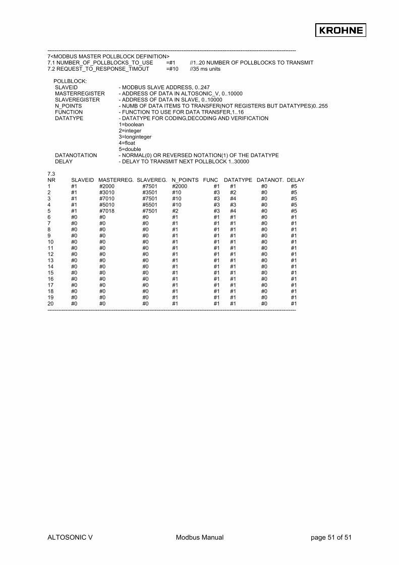
ALTOSONIC V Modbus Manual page 51 of 51
------------------------------------------------------------------------------------------------------------------------------------------- 7<MODBUS MASTER POLLBLOCK DEFINITION> 7.1 NUMBER_OF_POLLBLOCKS_TO_USE =#1 //1..20 NUMBER OF POLLBLOCKS TO TRANSMIT 7.2 REQUEST_TO_RESPONSE_TIMOUT =#10 //35 ms units POLLBLOCK: SLAVEID - MODBUS SLAVE ADDRESS, 0..247 MASTERREGISTER - ADDRESS OF DATA IN ALTOSONIC_V, 0..10000 SLAVEREGISTER - ADDRESS OF DATA IN SLAVE, 0..10000 N_POINTS - NUMB OF DATA ITEMS TO TRANSFER(NOT REGISTERS BUT DATATYPES)0..255 FUNCTION - FUNCTION TO USE FOR DATA TRANSFER,1..16 DATATYPE - DATATYPE FOR CODING,DECODING AND VERIFICATION 1=boolean 2=integer 3=longinteger 4=float 5=double DATANOTATION - NORMAL(0) OR REVERSED NOTATION(1) OF THE DATATYPE DELAY - DELAY TO TRANSMIT NEXT POLLBLOCK 1..30000 7.3 NR SLAVEID MASTERREG. SLAVEREG. N_POINTS FUNC DATATYPE DATANOT. DELAY 1 #1 #2000 #7501 #2000 #1 #1 #0 #5 2 #1 #3010 #3501 #10 #3 #2 #0 #5 3 #1 #7010 #7501 #10 #3 #4 #0 #5 4 #1 #5010 #5501 #10 #3 #3 #0 #5 5 #1 #7018 #7501 #2 #3 #4 #0 #5 6 #0 #0 #0 #1 #1 #1 #0 #1 7 #0 #0 #0 #1 #1 #1 #0 #1 8 #0 #0 #0 #1 #1 #1 #0 #1 9 #0 #0 #0 #1 #1 #1 #0 #1 10 #0 #0 #0 #1 #1 #1 #0 #1 11 #0 #0 #0 #1 #1 #1 #0 #1 12 #0 #0 #0 #1 #1 #1 #0 #1 13 #0 #0 #0 #1 #1 #1 #0 #1 14 #0 #0 #0 #1 #1 #1 #0 #1 15 #0 #0 #0 #1 #1 #1 #0 #1 16 #0 #0 #0 #1 #1 #1 #0 #1 17 #0 #0 #0 #1 #1 #1 #0 #1 18 #0 #0 #0 #1 #1 #1 #0 #1 19 #0 #0 #0 #1 #1 #1 #0 #1 20 #0 #0 #0 #1 #1 #1 #0 #1 -------------------------------------------------------------------------------------------------------------------------------------------

AustraliaKROHNE Australia Pty Ltd.Unit 19 No.9, Hudson Ave.Castle Hill 2154, NSWTEL.: +61(0)2-98948711FAX: +61(0)2-98994855e-mail: [email protected]
AustriaKROHNE Austria Ges.m.b.H.Modecenterstraße 14A-1030 WienTEL.: +43(0)1/203 45 32FAX: +43(0)1/203 47 78e-mail: [email protected]
BelgiumKROHNE Belgium N.V.Brusselstraat 320B-1702 Groot BijgaardenTEL.: +32(0)2-4 66 00 10FAX: +32(0)2-4 66 08 00e-mail: [email protected]
BrazilKROHNE ConautControles Automaticos Ltda.Estrada Das Águas Espraiadas, 230 C.P. 5606835 - 080 EMBU - SPTEL.: +55(0)11-4785-2700FAX: +55(0)11-4785-2768e-mail: [email protected]
ChinaKROHNE Measurement Instruments Co. Ltd.Room 7E, Yi Dian Mansion746 Zhao Jia Bang RoadShanghai 200030TEL.: +86(0)21-64677163FAX: +86(0)21-64677166Cellphone: +86(0)139 1885890e-mail: [email protected]
CISKanex KROHNE Engineering AGBusiness-Centre Planeta, Office 403ul. Marxistskaja 3109147 Moscow/RussiaTEL.: +7(0)095-9117165FAX: +7(0)095-9117231e-mail: [email protected]
Czech RepublicKROHNE CZ, spol. s r.o.Sobesická 156CZ-63800 BrnoTEL.: +420 545 532 111FAX: +420 545 220 093e-mail: [email protected]
AlgeriaArgentinaBulgariaCamaroonCanadaChile ColumbiaCroatiaDenmarkEcuadorEgyptFinlandFrench AntillesGreeceGuineaHong KongHungaryIndonesiaIvory CoastIranIrelandIsrael
Japan JordanKuwaitMaroccoMauritiusMexicoNew ZealandPakistanPolandPortugalSaudi ArabiaSenegalSingaporeSlovakiaSloveniaSwedenTaiwanThailandTurkeyTunesiaVenezuelaYugoslavia
FranceKROHNE S.A.Usine des OrsBP 98F-26 103 Romans CedexTEL.: +33(0)4-75 05 44 00FAX: +33(0)4-75 05 00 48e-mail: [email protected]
GermanyKROHNE MesstechnikGmbH & Co. KGLudwig-Krohne-StraßeD-47058 DuisburgTEL.: +49(0)203-301-0FAX: +49(0)203-301 389e-mail: [email protected]
IndiaKROHNE Marshall Ltd.A-34/35, M.I.D.C.Industrial Area, H-Block,Pimpri Poona 411018TEL.: +91(0)20 -744 20 20FAX: +91(0)20 -744 20 40e-mail: [email protected]
ItalyKROHNE Italia Srl.Via V. Monti 75I-20145 MilanoTEL.: +39(0)2-4 30 06 61FAX: +39(0)2-43 00 66 66e-mail: [email protected]
KoreaHankuk KROHNE2 F, 599-1Banghwa-2-DongKangseo-KuSeoulTEL.: +82(0)2665-85 23-4FAX: +82(0)2665-85 25e-mail: [email protected]
NetherlandsKROHNE AltometerKerkeplaat 12 NL-3313 LC DordrechtTEL.: +31(0)78-6306300FAX: +31(0)78-6306390e-mail: [email protected]
KROHNE Nederland B.V.Kerkeplaat 12NL-3313 LC DordrechtTEL.: +31(0)78-6306200FAX: +31(0)78-6306405Service Direkt: +31(0)78-6306222e-mail: [email protected]
NorwayKROHNEInstrumentation A.S.Ekholtveien 114 NO-1526 MossP.O. Box 2178, NO-1521 MossTEL.: +47(0)69-264860FAX: +47(0)69-267333e-mail: [email protected]: www.krohne.no
South AfricaKROHNE Pty. Ltd.163 New RoadHalfway House Ext. 13MidrandTEL.: +27(0)11-315-2685FAX: +27(0)11-805-0531e-mail: [email protected]
SpainI.I. KROHNE Iberia, S.r.L.Poligono Industrial NiloCalle Brasil, n°. 5E-28806 Alcalá de Henares -MadridTEL.: +34(0)91-8 83 21 52FAX: +34(0)91-8 83 48 54e-mail: [email protected]
SwitzerlandKROHNE AGUferstr. 90CH-4019 BaselTEL.: +41(0)61-638 30 30FAX: +41(0)61-638 30 40e-mail: [email protected]
United KingdomKROHNE Ltd.Rutherford DrivePark Farm Industrial EstateWellingborough,Northants NN8 6AE, UKTEL.: +44(0)19 33-408 500FAX: +44(0)19 33-408 501e-mail: [email protected]
USAKROHNE Inc.7 Dearborn RoadPeabody, MA 01960TEL.: +1-978 535-6060FAX: +1-978 535-1720e-mail: [email protected]
Overseas Representatives
NetherlandsKROHNE Oil & Gas B.V.Kerkeplaat 18NL-3313 LC DordrechtTel: +31(0)78 - 63 06 300Fax: +31(0)78 - 63 06 404E-mail: [email protected]
Subject to change without notice


![MODBUS IINDUSTRIE sWETTERSTATIONNDUSTRIE …€¦ · MODBUS rain[e]one Modbus INDUSTRY Modbus Pyranometer THP[pro] Modbus rain one Modbus IN Wiegender Nieder-schlagssensor Windrichtung](https://img.dokumen.tips/doc/110x75/5eb88fa576fba607cd617fd5/modbus-iindustrie-swetterstationndustrie-modbus-raineone-modbus-industry-modbus.jpg)