Embed Size (px)
Citation preview
313 134 391 101 43/03
..........................................................................................................2 Einbauanleitung: Elektroanlage für Anhängevorrichtung ........................................2
..........................................................................................................7 Instructions de montage : Installation électrique pour dispositif d’attelage..........................7
..........................................................................................................12 Installation instructions: Electrical system for towing hitch.................................................12
.........................................................................................................17 Istruzioni per l'installazione: Impianto elettrico per il gancio di traino.......................................17
.........................................................................................................22 Inbouwinstructie: Elektrische installatie voor trekhaak.............................................22
..........................................................................................................27 Návod k instalaci: Elektrické zařízení pro závěsné zařízení .......................................27

Einbauanleitung: Elektroanlage für Anhängevorrichtung
2 313 134 391 101 43/03 M-Klasse W163
Einbauanleitung: Elektroanlage für Anhängevorrichtung
Allgemeine Daten
Artikelnummer Westfalia Fahrzeughersteller
Fahrzeug
313 134 300 113 DaimlerChrysler M-Klasse W163
Einbauanleitung: Elektroanlage für Anhängevorrichtung
M-Klasse W163 313 134 391 101 43/03 3
Wichtige Hinweise
Vor Arbeitsbeginn die Einbauanleitung lesen. Der Elektroeinbausatz darf nur von qualifiziertem Fachpersonal eingebaut werden.
Vorsicht - Batterie abklemmen! Beschädigung der KFZ-Elektronik, elektronisch gespeicherte Daten können verloren gehen. Vor Arbeitsbeginn den Fehlerspeicher auslesen.
Vor dem Bohren sicherstellen, dass sich keine Gegenstände, wie z. B. Leitungen, hinter den Verkleidungen befinden.
Hinweis Bei der Montage auf folgende Punkte besonders achten:
• Leitungen dürfen weder eingeklemmt noch beschädigt sein.
• Alle Dichtungselemente ordnungsgemäß anbringen.
• Die Steckdosendichtung muss auf dem Isolierschlauch positioniert werden und nicht auf den Einzeladern.
• Leitungen so verlegen, dass diese weder am Fahrzeug scheuern noch abknicken.
• Leitungen nicht in unmittelbarer Nähe der Abgasanlage verlegen.
• Steuergeräte so anbringen, dass keine Feuchtigkeit eindringen kann. Der Kabelanschluss soll immer nach unten zeigen.
• Anhängersteuermodul entfetten, um eine bessere Haftung der Klebestellen zu gewährleisten.
Bei Anhängerbetrieb wird die Nebelschlussleuchte des Zugfahrzeugs abgeschaltet. Bei Anhängern ohne Nebelschlussleuchte muss diese nachgerüstet werden. Der Ausfall einer Blinkleuchte, auch am Anhänger, wird durch die Erhöhung der Blinkfrequenz angezeigt. Es ist keine zusätzliche Blinkkontrolle notwendig. Ein Steckdosenadapter darf nur im Anhängerbetrieb genutzt werden. Nach dem Anhängerbetrieb den Steckdosenadapter entfernen. Die Prüfung der Anhängerfunktionen mit einem Anhänger oder einem Prüfgerät mit Belastungswiderständen durchführen. Technische Änderungen vorbehalten!
Einbauanleitung: Elektroanlage für Anhängevorrichtung
4 313 134 391 101 43/03 M-Klasse W163
Einbauübersicht
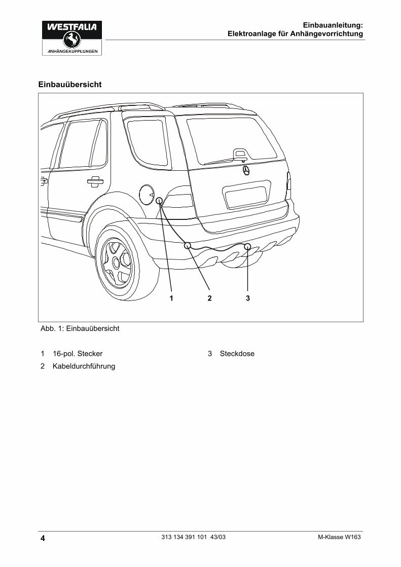
Abb. 1: Einbauübersicht 1 16-pol. Stecker 3 Steckdose 2 Kabeldurchführung
1 2 3
Einbauanleitung: Elektroanlage für Anhängevorrichtung
M-Klasse W163 313 134 391 101 43/03 5
Elektroanlage einbauen
1. Masseklemme der Batterie abklemmen. 2. Die kleine Abdeckung in der linken Seitenwandverkleidung entnehmen. 3. Das Leitungsende durch die Kabel-Durchführung, ausgehend vom Kofferraum, nach außen
zum Steckdosenhalteblech (Abb. 1/3) verlegen. 4. Die Gummitülle in die Kabel-Durchführung (Abb. 1/2) einsetzen. 5. Wenn ein Kabel und die Gummitülle bereits vorhanden sind, die vorhandene Gummitülle
entfernen. Bei der Gummitülle am Steckdosenstrang einen Schlitz einschneiden. Das zweite Kabel in den zweiten Durchgang der Gummitülle einführen und abdichten. 6. Den Kontakteinsatz in das Steckdosengehäuse eindrücken. 7. Das 3-polige Gehäuse auf den Mikroschalter in der Steckdose schieben und die
Gummidichtung an die Steckdose heranschieben. Kontakteinsatz muss einrasten! 8. Die Steckdose mit den beiliegenden Schrauben und Muttern am Halteblech (Abb. 1/3)
festschrauben. 9. Den Leitungsstrang mit Kabelbindern befestigen.
Anhängersteuermodul anschließen
10. Den 16-poligen Stecker (Abb. 1/1) mit dem passenden Gegenstück (befindet sich in der Nähe des Tankrohrs) zusammenstecken und befestigen.
11. Beiliegende 25A-Sicherung an Position F 18 an der E-Box/Sicherungsleiste vorne stecken.
Nebelschlussleuchte anschließen
Hinweis Zum Ausmessen der fahrzeugseitigen Signale geeignete Messgeräte verwenden!
12. Die grau/grüne Leitungsbrücke, die an der weißen Einzelleitung am Leitungsstrang angebunden ist, mittig durchtrennen und beide Enden 8-10 mm abisolieren und verzinnen.
13. Vom Fahrzeugleitungsstrang die grau/grüne Leitung zur Nebelschlussleuchte ausmessen und durchtrennen, abisolieren und verzinnen. Jeweils ein Ende mit je einer grau/grünen Einzelleitung fachgerecht verbinden und isolieren.
14. Die drei Leitungsenden mit Flachsteckhülsen wie folgt auf das beiliegende Relais stecken: Relais-Kontakt 85: weiße Einzelleitung aus Westfalia-Leitungsstrang Relais-Kontakt 86: grau/grüne Leitung, die vom Nebelschlussleuchten-Schalter kommt Relais-Kontakt 87a: grau/grüne Leitung, die zur Nebelschlussleuchte im Fahrzeug geht.

Einbauanleitung: Elektroanlage für Anhängevorrichtung
6 313 134 391 101 43/03 M-Klasse W163
Funktion prüfen
15. Masse der Fahrzeugbatterie wieder anschließen. 16. Die Anhängerfunktionen mit einem geeigneten Prüfgerät (mit Belastungswiderständen) oder
Anhänger prüfen. 17. Alle Leitungen mit Kabelbindern befestigen. 18. Alle ausgebauten Teile wieder einbauen.
Steckdosenbelegung
Kontakt Stromkreis Leitungsfarbe 1 Blinkleuchte, links schwarz/weiß
2 Nebelschlussleuchte weiß
3 Masse braun/weiß
4 Blinkleuchte, rechts schwarz/grün
5 Rückleuchte, rechts grau/rot
6 Bremsleuchte schwarz/rot
7 Rückleuchte, links grau/schwarz
8 Rückfahrscheinwerfer grün
9 Dauerplus rot
10 Ladeleitung --
11 Masse (Stromkreis 10) --
12 -- --
13 Masse (Stromkreis 9) braun
Instructions de montage : Installation électrique pour dispositif d’attelage
M-Klasse W163 313 134 391 101 43/03 7
Instructions de montage : Installation électrique pour dispositif d’attelage
Données générales
Numéro d'article Westfalia Fabricant du véhicule
Véhicule
313 134 300 113 DaimlerChrysler Classe M W163
Instructions de montage : Installation électrique pour dispositif d’attelage
8 313 134 391 101 43/03 M-Klasse W163
Remarques importantes
Avant de commencer l'intervention, lire les instructions d'installation. L'installation du module électronique ne doit être réalisée que par des techniciens qualifiés.
Attention - débrancher la batterie ! Endommagement de l'électronique du véhicule, les données enregistrées électroniquement peuvent être perdues. Extraire la mémoire des erreurs avant de commencer l'intervention.
Avant de commencer à percer, s'assurer que rien ne se trouve derrière le revêtement, comme des fils par exemple.
Remarque Observer avec attention les points suivants lors du montage :
• Les fils ne doivent pas être endommagés ou pincés.
• Installer tous les joints dans l'ordre établi.
• Le joint de la prise de courant doit être placé sur la gaine isolante et non sur un conducteur unique.
• Disposer les fils de façon à ce qu'ils ne puissent pas frotter sur le véhicule ou rompre.
• Ne pas placer les fils à proximité immédiate du système d'échappement.
• Brancher le dispositif de commande de manière à ce que l’humidité ne puisse pas s’infiltrer. Le raccord de câbles doit toujours être dirigé vers le bas.
• Dégraisser le module de commande du dispositif d'attelage afin de garantir une meilleure adhérence des joints de collage.
Lors de l'utilisation de l'attelage, les feux anti-brouillard arrières du véhicule tractant sont mis à l'arrêt. Pour les attelages sans feux anti-brouillard arrière, il faut en installer. Toute panne d'un clignotant, également au niveau de l'attelage, est indiquée par une augmentation de la fréquence de clignotement. Aucun dispositif de contrôle supplémentaire des clignotants n'est nécessaire. Un adaptateur de prise femelle ne doit être utilisé que pour le fonctionnement de l'attelage. Retirer cet adaptateur une fois que l'attelage n'est plus utilisé. Tester le fonctionnement de l'attelage avec un attelage ou un dispositif de contrôle avec une résistance fixe. Sous réserve de modifications techniques !
Instructions de montage : Installation électrique pour dispositif d’attelage
M-Klasse W163 313 134 391 101 43/03 9
Aperçu du montage
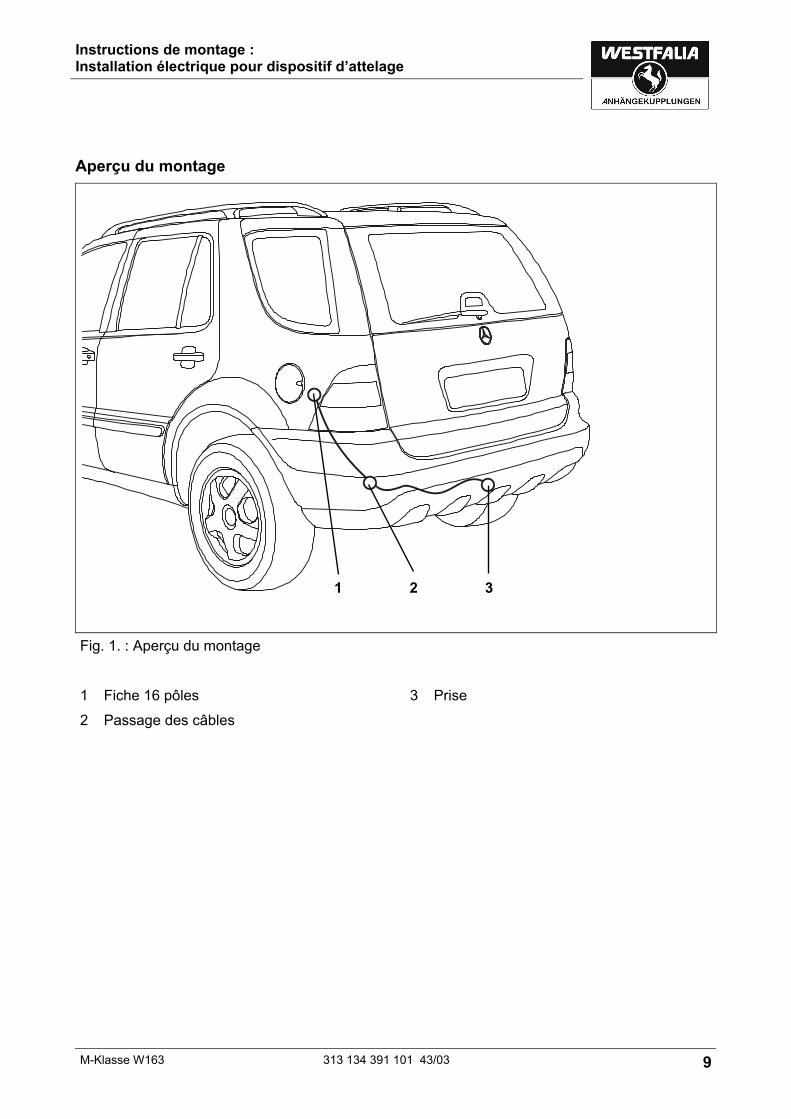
Fig. 1. : Aperçu du montage 1 Fiche 16 pôles 3 Prise 2 Passage des câbles
1 2 3

Instructions de montage : Installation électrique pour dispositif d’attelage
10 313 134 391 101 43/03 M-Klasse W163
Montage de l'installation électronique
1. Débrancher la borne de masse de la batterie. 2. Retirer le revêtement de petite taille du revêtement latéral gauche. 3. Faire passer l'extrémité du fil via le passage du câble, en partant du coffre à bagages vers
l'extérieur, jusqu'à la tôle de retenue de la prise (Fig. 1/3). 4. Insérer le passe-fil en caoutchouc dans le passage du câble (Fig. 1/2). 5. Si un câble et le passe-fil en caoutchouc sont déjà présents, retirer le passe-fil en
caoutchouc. Faire une encoche sur le conducteur de la prise au niveau du passe-fil en caoutchouc. Insérer et calfeutrer le second câble dans le deuxième passage du passe-fil en caoutchouc. 6. Appuyer le contact dans le bâti de la prise. 7. Pousser le bâti 3 pôles sur le microcontact dans la prise et faire glisser le joint en caoutchouc
sur la prise. Le contact doit s'insérer ! 8. Fixer la prise sur la plaque de retenue (Fig. 1/3) avec les vis et écrous fournis. 9. Fixer tous les conducteurs de fils avec des attaches-câbles.
Fixer le module de commande du dispositif d'attelage
10. Relier et fixer la fiche 16 pôles (Fig. 1/1) avec la fiche adaptée (qui se trouve près du tuyau du réservoir).
11. Insérer le fusible 25 A fourni sur l'emplacement F 18 sur la barre de fusibles/le boîtier électrique avant.
Connecter le feu anti-brouillard
Remarque Utiliser des appareils de mesure spéciaux pour la mesure des signaux côté véhicule !
12. Séparer en son milieu le pont de fil gris/vert qui est relié au fil unique blanc sur le conducteur de fils et étainer et isoler les deux extrémités sur 8-10 mm.
13. Mesure le fil gris/vert du conducteur de fils du véhicule jusqu'au feu anti-brouillard. Le séparer, l'isoler et l'étainer. Relier et isoler correctement chaque extrémité avec un fil unique gris/vert.
14. Insérer les trois extrémités de fil avec contact femelle à fiche plate comme suit sur le relais présent. Contact relais 85 : Fil unique blanc du conducteur de fil Westfalia Contact relais 86 : Fil gris/vert qui provient de la commande des feux anti-brouillard Contact relais 87a : Fil gris/vert qui se dirige dans le véhicule vers les feux anti-brouillard.
Instructions de montage : Installation électrique pour dispositif d’attelage
M-Klasse W163 313 134 391 101 43/03 11
Vérifier le fonctionnement
15. Reconnecter la masse de la batterie du véhicule. 16. Vérifier le fonctionnement de l'attelage avec un dispositif de contrôle adéquat (avec
résistance fixe) ou un attelage. 17. Fixer tous les fils avec des attaches-câbles. 18. Remonter toutes les pièces qui ont été démontées.
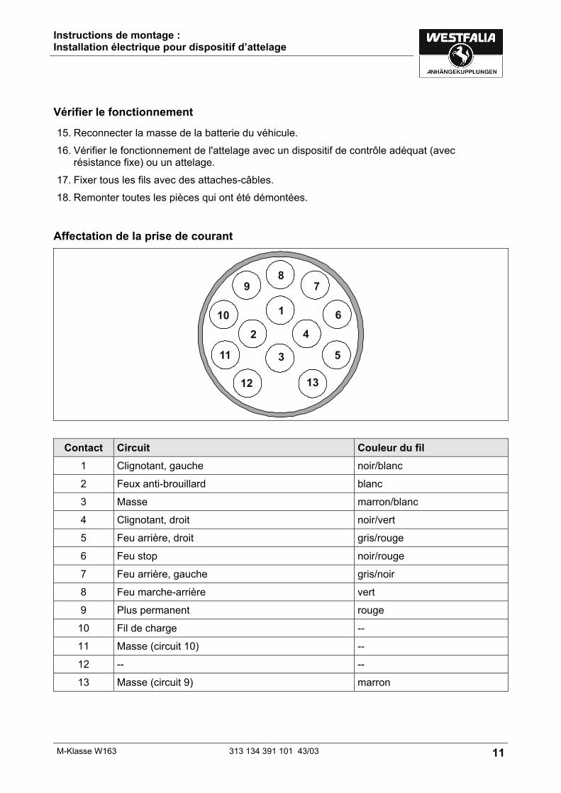
Affectation de la prise de courant
Contact Circuit Couleur du fil 1 Clignotant, gauche noir/blanc
2 Feux anti-brouillard blanc
3 Masse marron/blanc
4 Clignotant, droit noir/vert
5 Feu arrière, droit gris/rouge
6 Feu stop noir/rouge
7 Feu arrière, gauche gris/noir
8 Feu marche-arrière vert
9 Plus permanent rouge
10 Fil de charge --
11 Masse (circuit 10) --
12 -- --
13 Masse (circuit 9) marron
Installation instructions: Electrical system for towing hitch
12 313 134 391 101 43/03 M-Klasse W163
Installation instructions: Electrical system for towing hitch
General data
Part number Westfalia Vehicle Manufacturer
Vehicle
313 134 300 113 DaimlerChrysler M Class W163

Installation instructions: Electrical system for towing hitch
M-Klasse W163 313 134 391 101 43/03 13
Important notes
Read the installation manual prior to starting work. The electrical kit should only be installed by qualified personnel.
Caution – Disconnect the battery! Danger of damage to the vehicle’s electronic system. Data which are stored electronically may get lost. Read out the fault storage prior to starting work.
Make sure prior to drilling that no objects such as cables, for example, are located behind the covers.
Note During installation special attention has to be paid to the following points:
• Cables must not be pinched or damaged.
• All sealing elements have to be installed properly.
• The socket gasket has to be positioned on the insulating sleeve and not on the individual wires.
• Lay the cables such that they do not rub on the vehicle and are not bent.
• Do not lay any cables near the exhaust system.
• Install the controller such that it is protected against the ingress of humidity. The cable connection should always face downward.
• Degrease the trailer control module to ensure better adhesion on the adhesion points. When a trailer is used, the rear fog lamp of the traction vehicle is deactivated. In the case of trailers without rear fog lamp, a rear fog lamp has to be retrofitted. When a direction indicator lamp fails, also on the trailer, this is indicated by a higher flashing frequency. No additional direction indicator check is necessary. A socket adapter may only be used in conjunction with a trailer. When the trailer is no longer used, remove the socket adapter. Correct trailer operation has to be checked using a trailer or a test instrument with load resistors. Subject to technical alterations!
Installation instructions: Electrical system for towing hitch
14 313 134 391 101 43/03 M-Klasse W163
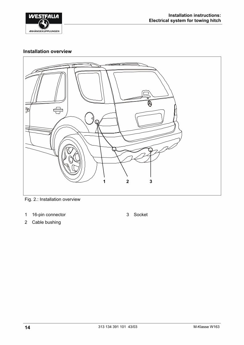
Installation overview
Fig. 2.: Installation overview 1 16-pin connector 3 Socket 2 Cable bushing
1 2 3

Installation instructions: Electrical system for towing hitch
M-Klasse W163 313 134 391 101 43/03 15
Installing the electrical system
1. Disconnect the ground terminal of the battery. 2. Remove the small cover in the left side panel covering. 3. Starting in the luggage trunk, lead the cable end through the cable leadthrough to the outside
up to the socket holder plate (Fig. 1/3). 4. Insert the rubber grommet into the cable leadthrough (Fig. 1/2). 5. If there is already a cable and the rubber grommet, remove the existing rubber grommet. Cut a slot into the rubber grommet on the socket cable harness. Introduce the second cable into the second hole of the rubber grommet and seal it. 6. Press the contact insert into the socket housing. 7. Push the 3-pin housing on the microswitch inside the socket and push the rubber grommet
towards the socket. Make sure that the contact insert locks into place! 8. Screw the socket onto the holding plate (Fig. 1/3) using the supplied screws and nuts. 9. Secure the cable harness using cable ties.
Connecting the trailer control module
10. Connect the 16-pin connector (Fig. 1/1) with its matching counterpart (located near the fuel tank tube) and fasten it.
11. Insert the enclosed 25 A fuse into position F 18 in the electrical box/fuse holder at the front.
Connecting the rear fog lamp
Note Use appropriate measuring instruments to measure the vehicle signals!
12. Cut the gray/green bridge connected to the single white line of the cable harness in the middle, strip the cable ends by 8-10 mm and tin-coat them.
13. Measure the gray/green line of the vehicle's cable harness leading to the rear fog lamp and cut it, strip the ends and tin-coat them. Connect each end with one gray/green single line and insulate them.
14. Connect the three cable ends to the enclosed relay as follows, using quick-connect receptacles. Relay contact 85: White single line from Westfalia cable harness Relay contact 86: Gray/green line coming from the rear fog lamp switch Relay contact 87a: Gray/green line leading to the rear fog lamp inside the vehicle.
Checking correct operation
15. Reconnect the ground of the vehicle’s battery.
Installation instructions: Electrical system for towing hitch
16 313 134 391 101 43/03 M-Klasse W163
16. Check the trailer function with the help of a suitable test instrument (with load resistors) or with the help of a trailer.
17. Secure all cables using cable ties. 18. Refit any parts removed for installation.
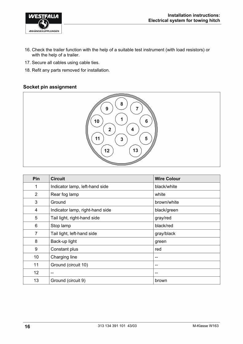
Socket pin assignment
Pin Circuit Wire Colour 1 Indicator lamp, left-hand side black/white
2 Rear fog lamp white
3 Ground brown/white
4 Indicator lamp, right-hand side black/green
5 Tail light, right-hand side gray/red
6 Stop lamp black/red
7 Tail light, left-hand side gray/black
8 Back-up light green
9 Constant plus red
10 Charging line --
11 Ground (circuit 10) --
12 -- --
13 Ground (circuit 9) brown
Istruzioni per l'installazione: Impianto elettrico per il gancio di traino
M-Klasse W163 313 134 391 101 43/03 17
Istruzioni per l'installazione: Impianto elettrico per il gancio di traino
Dati in generale
Codice articolo Westfalia Costruttore veicolo
Veicolo
313 134 300 113 DaimlerChrysler Classe M W163
Istruzioni per l'installazione: Impianto elettrico per il gancio di traino
18 313 134 391 101 43/03 M-Klasse W163
Note importanti
Prima di iniziare i lavori, leggere le istruzioni di montaggio. Il kit elettrico deve essere montato solo da personale qualificato.
Attenzione - Staccare la batteria! Danni all'elettronica del veicolo, i dati memorizzati possono essere persi. Prima di iniziare consultare la memoria degli errori.
Prima di forare assicurarsi che dietro al rivestimento non ci siano oggetti, come per es. cablaggi.
Nota Durante il montaggio prestare molta attenzione a quanto segue:
• I cavi non devono essere bloccati o danneggiati.
• Posizionare tutte le guarnizioni a regola d'arte.
• La guarnizione della presa deve essere posizionata sulla guaina isolante e non sui singoli fili.
• Posare i cablaggi in modo tale, che non sfreghino contro il veicolo e non risultino piegati.
• Non posare i cablaggi nelle immediate vicinanze dell'impianto gas di scarico.
• Montare le centraline in modo tale che non possa entrare umidità. Il collegamento del cavo deve essere sempre rivolto verso il basso.
• Sgrassare il modulo di comando rimorchio per migliorare l'adesione delle aree di incollaggio.
In caso di funzionamento con rimorchio viene spenta la luce retronebbia del veicolo. In caso di rimorchi non corredati di luce retronebbia, questa dovrà essere prevista. Il guasto al lampeggiante direzionale, viene indicato anche al rimorchio con l'aumento dell'intermittenza. Non è necessario altro dispositivo di controllo del lampeggio. La presa adattatore può essere impiegata solo in presenza del rimorchio. Staccando il rimorchio togliere anche la presa adattatore. Verificare le funzioni con il rimorchio stesso oppure un dispositivo di misurazione con resistenze di carico. Con riserva di modifiche tecniche!
Istruzioni per l'installazione: Impianto elettrico per il gancio di traino
M-Klasse W163 313 134 391 101 43/03 19
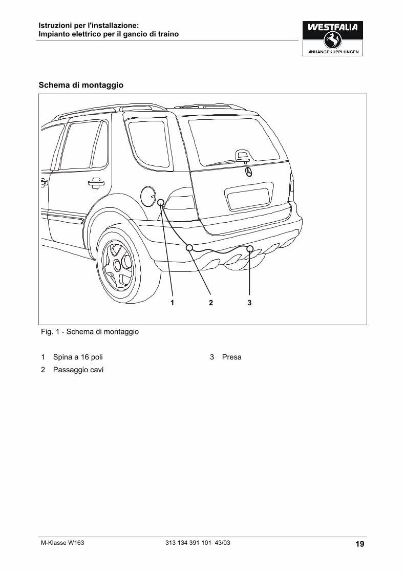
Schema di montaggio
Fig. 1 - Schema di montaggio 1 Spina a 16 poli 3 Presa 2 Passaggio cavi
1 2 3
Istruzioni per l'installazione: Impianto elettrico per il gancio di traino
20 313 134 391 101 43/03 M-Klasse W163
Montaggio dell'impianto elettrico
1. Staccare il morsetto di massa dalla batteria. 2. Togliere la piccola copertura nel rivestimento laterale sinistro. 3. Infilare il terminale del fascio di cavi attraverso l'apposita apertura, partendo dal bagagliaio,
verso l'esterno sino alla lamiera portapresa (fig. 1/3). 4. Infilare la bussola di gomma nel foro di passaggio cavi (fig. 1/2). 5. Se un cavo e la bussola di gomma sono già presenti, togliere quest'ultima. Tagliare una fessura nella bussola di gomma del fascio di cavi della presa. Infilare il secondo cavo nel secondo foro della bussola di gomma ed ermetizzare. 6. Premere il contatto ad innesto nel corpo della presa. 7. Applicare il corpo a 3 poli sul microinterruttore della presa ed avvicinare la guarnizione di
gomma alla presa. Il contatto ad innesto deve innestarsi correttamente! 8. Fissare la presa al supporto (fig. 1/3) mediante le viti ed i dadi forniti in dotazione. 9. Fissare il fascio di cavi con fascette stringicavo.
Collegamento del modulo di comando rimorchio
10. Collegare insieme la spina a 16 poli (fig. 1/1) ed il relativo connettore (si trova in prossimità del tubo del serbatoio) e fissare.
11. Applicare il fusibile da 25 A fornito in dotazione sulla posizione F 18 della scatola/striscia portafusibili.
Collegamento del retronebbia
Nota Per il rilevamento dei segnali del veicolo impiegare gli strumenti di misura idonei!
12. Tagliare al centro il ponticello grigio/verde collegato al conduttore bianco del fascio di cavi e spelare e stagnare entrambe le estremità per un tratto di 8-10 mm.
13. Misurare il conduttore grigio/verde del fascio di cavi del veicolo fino al retronebbia, quindi tagliarlo a misura, spelarlo e stagnarlo. Collegare ed isolare correttamente un'estremità con il conduttore grigio/verde.
14. Inserire le tre estremità con spinotti piatti nel relè fornito in dotazione nel modo seguente: Contatto relè 85: conduttore bianco del fascio di cavi Westfalia; Contatto relè 86: conduttore grigio/verde proveniente dall'interruttore retronebbia; Contatto relè 87a: conduttore grigio/verde verso il retronebbia nel veicolo.
Verifica del funzionamento
15. Ricollegare la massa della batteria del veicolo.
Istruzioni per l'installazione: Impianto elettrico per il gancio di traino
M-Klasse W163 313 134 391 101 43/03 21
16. Verificare il funzionamento del rimorchio mediante dispositivo idoneo (con resistenze di carico) o collegando il rimorchio stesso.
17. Fissare tutti i cavi con fascette stringicavo. 18. Rimontare tutte le parti smontate precedentemente.
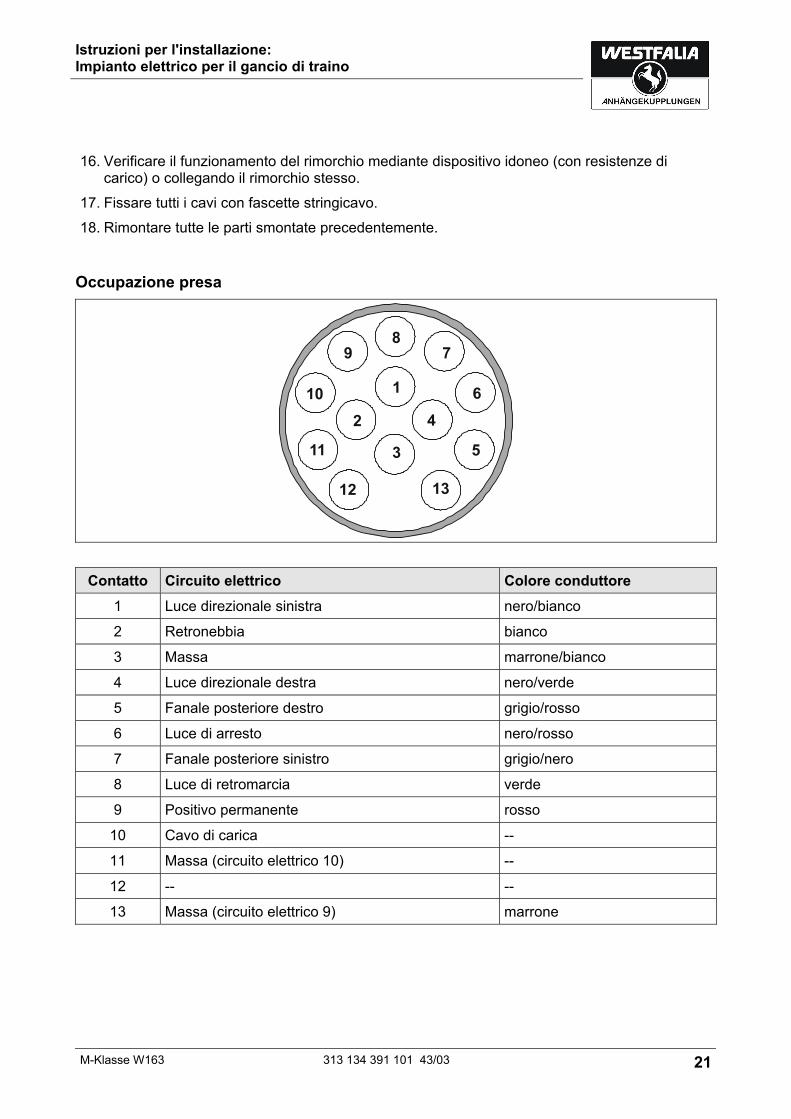
Occupazione presa
Contatto Circuito elettrico Colore conduttore 1 Luce direzionale sinistra nero/bianco
2 Retronebbia bianco
3 Massa marrone/bianco
4 Luce direzionale destra nero/verde
5 Fanale posteriore destro grigio/rosso
6 Luce di arresto nero/rosso
7 Fanale posteriore sinistro grigio/nero
8 Luce di retromarcia verde
9 Positivo permanente rosso
10 Cavo di carica --
11 Massa (circuito elettrico 10) --
12 -- --
13 Massa (circuito elettrico 9) marrone
Inbouwinstructie: Elektrische installatie voor trekhaak
22 313 134 391 101 43/03 M-Klasse W163
Inbouwinstructie: Elektrische installatie voor trekhaak
Algemene gegevens
Artikelnummer Westfalia Fabrikant voertuig
Voertuig
313 134 300 113 DaimlerChrysler M-klasse W163
Inbouwinstructie: Elektrische installatie voor trekhaak
M-Klasse W163 313 134 391 101 43/03 23
Belangrijke opmerkingen
Lees voor begin van de werkzaamheden de montagehandleiding door. Het elektrische montageset mag uitsluitend worden gemonteerd door gekwalificeerd personeel.
Pas op – accu afklemmen! Beschadiging van de voertuigelektronica, elektronisch bewaarde gegevens kunnen verloren gaan. Voor begin van de werkzaamheden foutgeheugen uitlezen.
Zorg voor het boren ervoor dat zich geen voorwerpen zoals b. v. leidingen achter de bekleding bevinden.
Pas op Let bij de montage vooral op de volgende punten:
• Leidingen mogen noch worden ingeklemd noch beschadigd.
• Alle dichtingselementen goed bevestigen.
• De stopcontactpakking moet op de isolatieslang worden gepositioneerd en niet op de enkelvoudige aders.
• Leidingen zo leggen dat deze noch aan het voertuig wrijven noch knikken.
• Leidingen niet in de directe nabijheid van de uitlaatinstallatie leggen.
• Regelapparaten dusdanig monteren dat geen vochtigheid binnen kan dringen. De kabelaansluiting moet altijd naar beneden wijzen.
• Besturingsmodule van de aanhanger ontvetten om een betere hechting van de plakplaats te garanderen.
Bij rijden met een aanhanger wordt de mistachterlamp van het trekvoertuig uitgeschakeld. Bij aanhangers zonder mistachterlamp moet deze achteraf worden geïnstalleerd. Wanneer een richtingaanwijzer uitvalt, ook op de aanhanger, wordt dit aangegeven door het verhogen van de knipperfrequentie. Een aanvullende controle van de richtingsaanwijzers is niet nodig. Een adapter voor de contactdoos mag uitsluitend worden gebruikt bij het rijden met aanhanger. Daarna moet de adapter worden verwijderd. Controleer de aanhangerfuncties door het aansluiten aan een aanhanger of m.b.v. een testapparaat met belastingsweerstanden. Technische wijzigingen voorbehouden!
Inbouwinstructie: Elektrische installatie voor trekhaak
24 313 134 391 101 43/03 M-Klasse W163
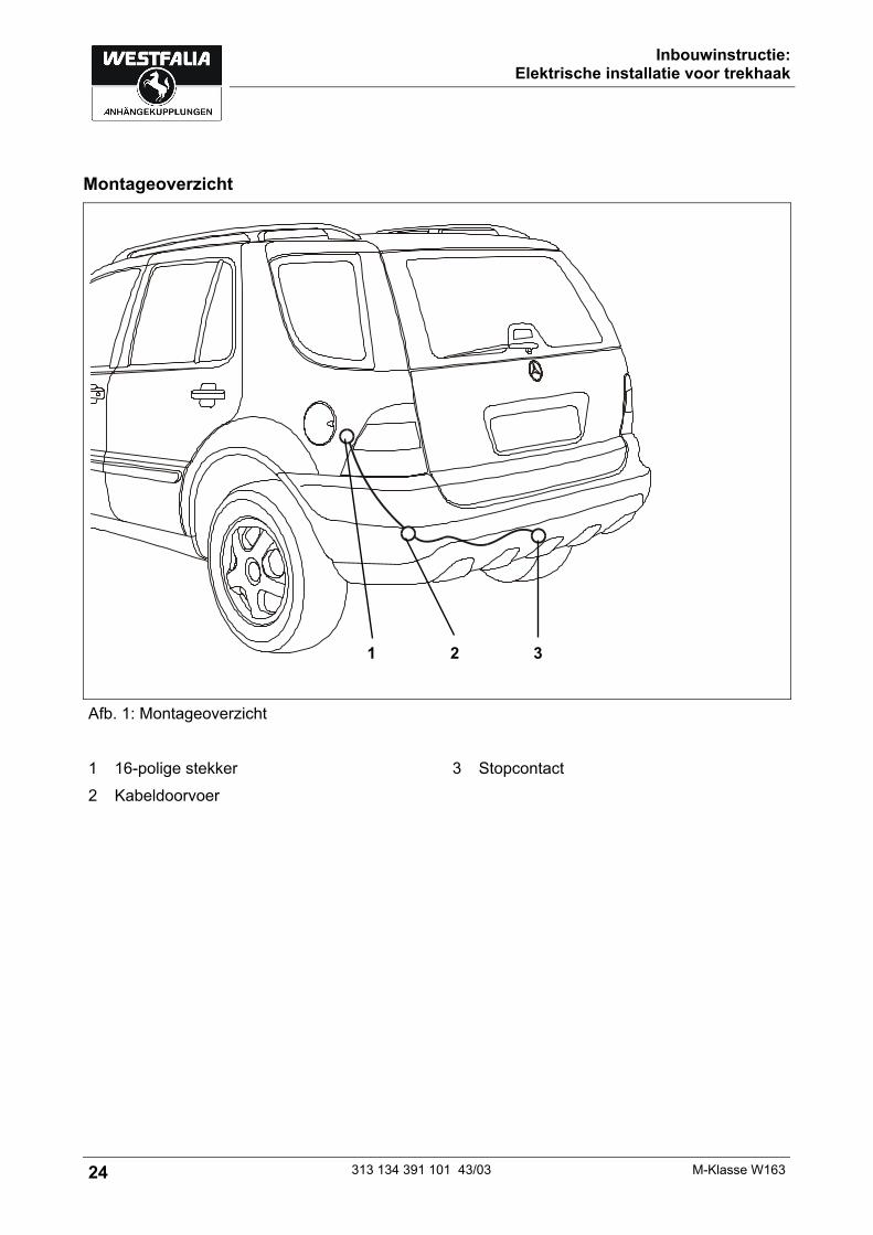
Montageoverzicht
Afb. 1: Montageoverzicht 1 16-polige stekker 3 Stopcontact 2 Kabeldoorvoer
1 2 3

Inbouwinstructie: Elektrische installatie voor trekhaak
M-Klasse W163 313 134 391 101 43/03 25
Elektrische installatie inbouwen 1. Massaklem van de accu afklemmen. 2. De kleine afdekking van de linker zijwandbekleding verwijderen. 3. Het kabeleinde door de kabeldoorvoer leggen. Daarbij van de kofferbak uitgaan en de kabel
dan naar buiten naar de stopcontact-bevestigingsplaat (afb. 1/3) leggen. 4. De rubberbus in de kabeldoorvoer (afb. 1/2) plaatsen. 5. Als een kabel en de rubberbus reeds aanwezig is, kunt u de aanwezige rubberbus
verwijderen. Breng een sleuf aan op de rubberbus van de stopcontact-strook. De tweede kabel in de tweede doorvoer van de rubberbus plaatsen en afdichten. 6. Het contact-inzetstuk in het huis van de stopcontact induwen. 7. Het 3-polige huis op de microschakelaar in het stopcontact plaatsen en de rubberen pakking
tegen het stopcontact schuiven. Het contact-inzetstuk moet inklikken! 8. Het stopcontact op de montageplaat (afb. 1/3) vastschroeven met de meegeleverde
schroeven en moeren. 9. De kabelbundel met kabelbinders bevestigen.
Besturingsmodule van de aanhanger aansluiten
10. De 16-polige stekker (afb. 1/1) met het passende contradeel (bevindt zich in de nabijheid van de tankbuis) verbinden en vastmaken.
11. De meegeleverde 25 A zekering op positie F 18 van de elektronicabox/zekeringslijst (voren) plaatsen.
Mistachterlamp aansluiten
Pas op Gebruik voor het meten van de voertuigsignalen hiervoor geschikte meetapparaten!
12. De grijs/groene jumper die met de witte enkelvoudige leiding van de kabelbundel verbonden is, door het midden doorknippen en beiden uiteinden op een lengte van 8-10 mm isoleren en vertinnen.
13. De grijs/groene leiding uit de voertuig-leidingbundel uitmeten die naar de mistachterlamp leidt. Dan deze leiding doorknippen, isoleren en vertinnen. De uiteinden telkens met één grijs/groene enkelvoudige leiding vakkundig verbinden en isoleren.
14. De drie leidingseinden met vlakke insteekbussen als volgt op het meegeleverde relais steken: Relais-contact 85: witte enkelvoudige leiding uit de Westfalia-leidingbundel Relais-contact 86: grijs/groene leiding die vanuit de mistachterlamp-schakelaar komt Relais-contact 87a: grijs/groene leiding die naar de mistachterlamp van het voertuig leidt.

Inbouwinstructie: Elektrische installatie voor trekhaak
26 313 134 391 101 43/03 M-Klasse W163
Functie controleren
15. Sluit de massa van de accu weer aan. 16. De aanhangerfuncties m.b.v. een geschikt testapparaat (met belastingsweerstanden) of
aanhanger controleren. 17. Alle leidingen met kabelbinders bevestigen. 18. Alle gedemonteerde onderdelen weer plaatsen.
Aansluitschema van het stopcontact
Contact Stroomkring Kleur van de leiding 1 Knipperlicht, links zwart/wit
2 Mistachterlamp wit
3 Massa bruin/wit
4 Knipperlicht rechts zwart/groen
5 Achterlamp rechts grijs/rood
6 Remlicht zwart/rood
7 Achterlamp links grijs/zwart
8 Achteruitrijlamp groen
9 Continu plus rood
10 Ladeleiding --
11 Massa (stroomkring 10) --
12 -- --
13 Massa (stroomkring 9) bruin

Návod k instalaci: Elektrické zařízení pro závěsné zařízení
M-Klasse W163 313 134 391 101 43/03 27
Návod k instalaci: Elektrické zařízení pro závěsné zařízení
Všeobecná data
Číslo zboží Westfalia Výrobce vozidla
Vozidlo
313 134 300 113 DaimlerChrysler model M W163
Návod k instalaci: Elektrické zařízení pro závěsné zařízení
28 313 134 391 101 43/03 M-Klasse W163
Důležitá upozornění
Před začátkem práce si přečtěte návod k montáži. Elektrickou sadu smí instalovat pouze kvalifikovaný odborný personál.
Pozor – odpojte akumulátor! Poškození elektroniky motorového vozidla, případná ztráta elektronicky do paměti uložených dat. Před začátkem práce vyčtěte paměť poruch.
Před vrtáním se ujistěte, že se za obloženími nenachází žádné předměty jako např. vodiče.
Upozornění Při montáži dbejte zvláště na následující body:
• Vedení nesmí být přiskřípnuta nebo poškozena.
• Všechny těsnicí prvky řádně připevněte.
• Těsnění zásuvky musí být umístěno na izolační hadici a ne na jednotlivých žilách.
• Vodiče veďte tak, aby se nedřely o vozidlo nebo se nezlomily.
• Vodiče neveďte v bezprostřední blízkosti výfuku.
• Řídicí jednotky připevněte tak, aby do nich nemohla vniknout vlhkost. Kabelová přípojka musí vždy ukazovat dolů.
• Na zvýšení přilnavosti lepených míst, odmastěte řídící modul přívěsu. Při jízdě s přívěsem se vypne koncové mlhové světlo vozidla. U přívěsů bez koncového mlhového světla, se toto světlo musí dodatečně instalovat. Přerušení funkce světla ukazatele směru jízdy, i na přívěsu, je signalizováno zvýšením frekvence blikání. Dodatečná kontrola blikání není nutná. Adaptér zásuvky se smí používat pouze při jízdě s přívěsem. Po ukončení jízdy s přívěsem, adaptér zásuvky odstraňte. Funkce přívěsu kontrolujte přímo prostřednictvím přívěsu nebo pomocí kontrolního přístroje se zatěžovacími odpory. Technické změny vyhrazeny!

Návod k instalaci: Elektrické zařízení pro závěsné zařízení
M-Klasse W163 313 134 391 101 43/03 29
Přehled montáže
Obr. 1: Přehled montáže 1 16pólová zástrčka 3 Zásuvka 2 Kabelová průchodka
1 2 3

Návod k instalaci: Elektrické zařízení pro závěsné zařízení
30 313 134 391 101 43/03 M-Klasse W163
Montáž elektrického zařízení
1. Odpojte zemnicí svorku akumulátoru. 2. Odeberte malý kryt v obložení levé stěny. 3. Konec vedení veďte kabelovou průchodkou ze zavazadlového prostoru, směrem ven k
plechovému držáku zásuvky (obr. 1/3). 4. Pryžovou průchodku vsaďte do otvoru pro kabel (obr. 1/2). 5. Pokud již existuje kabel a pryžová průchodka, odstraňte existující průchodku. Do pryžové průchodky u svazku vodičů zásuvky udělejte zářez. Veďte druhý kabel druhým průchodem pryžové průchodky a utěsněte jej. 6. Vtlačte vložku s kontakty do pouzdra zásuvky. 7. Na mikrospínač v zásuvce nasuňte 3pólové pouzdro a pryžové těsnění přisuňte k zásuvce.
Dotyková vložka musí zaskočit! 8. Pomocí přiložených šroubů a matic přišroubujte zásuvku pevně k plechovému držáku
(obr. 1/3). 9. Svazek vodičů připevněte stahovacími sponami na kabely.
Připojení řídícího modulu přívěsu
10. Spojte 16pólový konektor (obr. 1/1) s vhodným protějškem (nachází se v nedaleko hrdla palivové nádrže) a upevněte jej.
11. Vsaďte přiloženou 25A pojistku na místo F 18 v krabici s elektronikou/pojistkové liště vpředu.
Připojení koncového světla do mlhy
Upozornění K proměření signálů vozidla použijte vhodné měřící přístroje!
12. Šedozelený kabelový můstek připevněný k bílému samostatnému vodiči svazku fázových vodičů v prostředku přestřihněte, odizolujte 8-10 mm na obou koncích a odizolované úseky pocínujte.
13. Vyměřte šedozelený vodič svazku fázových vodičů vozidla, vedoucí ke koncovému světla do mlhy, přestřihněte, odizolujte a pocínujte jej. Spojte odborně každý z konců se šedozeleným protějškem samostatného vodiče a spoje izolujte.
14. Podle následujícího popisu nasaďte všechny tři konce vodičů s plochými nástrčkami na přiložené relé. Reléový kontakt 85: bílý samostatný vodič ze svazku fázových vodičů Westfalia Reléový kontakt 86: šedozelený vodič od spínače koncových světel do mlhy Reléový kontakt 87a: šedozelený vodič, vedoucí ke koncovému světlu do mlhy, instalovaný
ve vozidle.
Návod k instalaci: Elektrické zařízení pro závěsné zařízení
M-Klasse W163 313 134 391 101 43/03 31
Kontrola funkce
15. Ukostřete opět akumulátor vozidla. 16. Funkce přívěsu přezkoušejte vhodným kontrolním přístrojem (se zatěžovacími odpory), nebo
pomocí přívěsu. 17. Všechna vedení připevněte stahovacími sponami na kabely. 18. Všechny vymontované díly opět zamontujte.
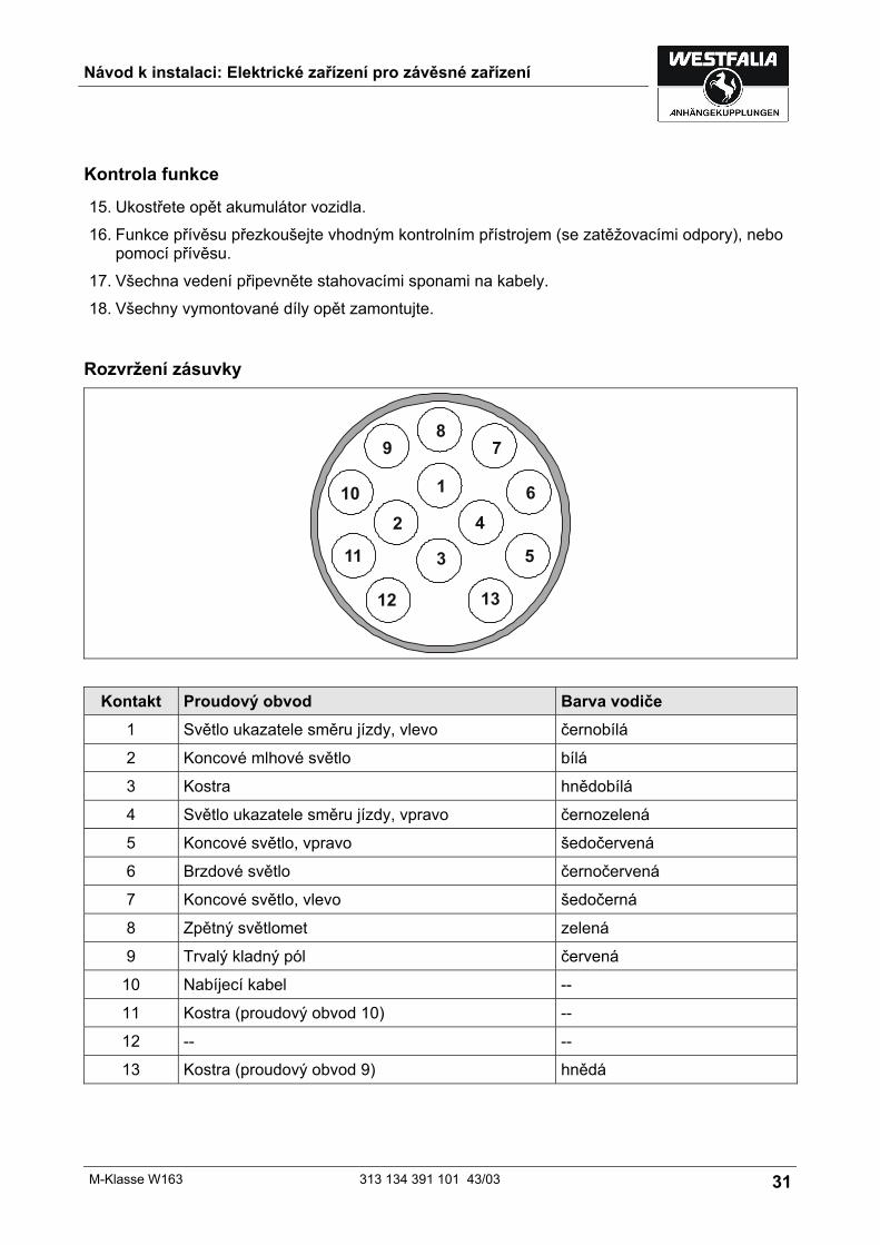
Rozvržení zásuvky
Kontakt Proudový obvod Barva vodiče 1 Světlo ukazatele směru jízdy, vlevo černobílá
2 Koncové mlhové světlo bílá
3 Kostra hnědobílá
4 Světlo ukazatele směru jízdy, vpravo černozelená
5 Koncové světlo, vpravo šedočervená
6 Brzdové světlo černočervená
7 Koncové světlo, vlevo šedočerná
8 Zpětný světlomet zelená
9 Trvalý kladný pól červená
10 Nabíjecí kabel --
11 Kostra (proudový obvod 10) --
12 -- --
13 Kostra (proudový obvod 9) hnědá