Embed Size (px)
Citation preview
8/3/2019 M. Busquet et al- Effect of lateral radiative losses on radiative shock propagation
http://slidepdf.com/reader/full/m-busquet-et-al-effect-of-lateral-radiative-losses-on-radiative-shock-propagation 1/4
Effect of lateral radiative losses on radiative shock propagation
M. Busquet a,*, E. Audit b, M. Gonzalez b, C. Stehle a, F. Thais b, O. Acef a, D. Bauduin a,P. Barroso a, B. Rus c, M. Kozlova c, J. Polan c, T. Mocek c
a LERMA, Observatoire de Paris, UPMC, CNRS, Place Jules Janssen, 92190 Meudon, Franceb Service d’Astrophysique, CEA-Saclay, Gif-sur-Yvette, Francec Institute of Physics, PALS Center, Prague, Czech Republic
Available online 4 February 2007
Abstract
Experimental and numerical studies of radiative shocks, of interest as scaled astrophysical objects, have been performed. Experiments were
conducted at the PALS facility in Prague with a xenon filled mini-shock tube using a laser accelerated plastic pusher. Numerical simulations of
the hydrodynamics including radiation effects have been performed with the 3D code HERACLES. Measurements have been made of the elec-
tronic density of the shocked gas and of the time history of the position of the radiative precursor. Simulations and experimental results show
good agreement when lateral radiative losses are taken into account, including a wall albedo of 40%.
Ó 2007 Elsevier B.V. All rights reserved.
Keywords: Radiative shocks; Laboratory astrophysics
1. Introduction
Radiative shocks can be defined as shocks of sufficient
strength that radiation arising from the compressed layer will
significantly alter the structure of the shock itself, with radiative
cooling of the downstream region and radiation heating and ion-
izing of a precursor. Radiative shocks are observed around astro-
nomical objects in a wide variety of environments, e.g.,
supernovae in their radiative cooling stage, bow shocks of stellar
jet in galactic medium, collision of interstellar clouds. Under-
standing the underlying physical phenomena is important for
the analysis of the time-dependence of these events. However,
each astronomical observation is unique and almost fixed in
time. Since the late 80s [1] there have been efforts by several
groups to scale these astrophysical events to accessible labora-
tory conditions for analytical and/or parametric studies. In this
study we explore radiative shocks produced by a laser in mini-
shock tube. [2e6]. In the experiment we performed on the
PALS laser facility in Prague, the aim was to study the time
history for a much longer time than in the experiment performed
inLULI [5] studying the slowing down of the radiative precursor
due to lateral radiative losses. As radiation emissivities and
opacities increase with the atomic number, we select xenon
for the medium in which the shock will propagate.
2. Target design, experimental setup and results
Thetargets aredesigned as mini-shock-tubes made of a 4 mm
long glass capillary with a square section of 700 mm filled with
xenon at 0.2 bar. A 1 cm3 reservoir prevents reduction of the xe-
non pressure during the 20 min between the filling and the lasershot. A 10 mm CH foil is glued at one end of the capillary and is
coated by a 0.5 mm layer of gold facing the xenon gas that pre-
vents preheating the gas by radiation and electrons created in the
expanding laser created corona. This foil is irradiated by the fre-
quencytripled( l ¼ 438 mm)iodine700 JPALSlaserwithapulse
duration of 0.35 ns, which is smoothed with a PZP-type random
phase plate to have a uniform focal spot of w650 mm with a re-
sulting intensity of up to 1.5Â 1014 W/cm2 on target. Laser ab-
lation of the front surface acceleratethe CH/Au pusher by rocket
effect and launches a strong shock in the gas. The laser pulse is* Corresponding author.
E-mail address: [email protected] (M. Busquet).
1574-1818/$ - see front matter Ó 2007 Elsevier B.V. All rights reserved.
doi:10.1016/j.hedp.2007.01.002
High Energy Density Physics 3 (2007) 8e11www.elsevier.com/locate/hedp
8/3/2019 M. Busquet et al- Effect of lateral radiative losses on radiative shock propagation
http://slidepdf.com/reader/full/m-busquet-et-al-effect-of-lateral-radiative-losses-on-radiative-shock-propagation 2/4
short enoughand the targetmassive enough that theback surface
of the pusher remains at solid density, launching a shock into the
unperturbed gas. The velocity of the pusher, which is computed
tobew65 km/s, atomic number and gas pressure give rise to the
formation of super-critical radiative shock [7e10]. To probe the
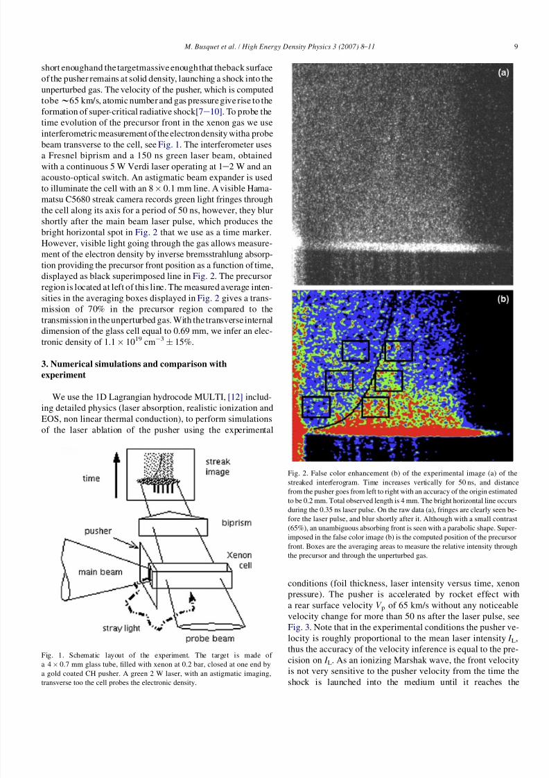
time evolution of the precursor front in the xenon gas we use
interferometric measurement of the electron density witha probebeam transverse to the cell, see Fig. 1. The interferometer uses
a Fresnel biprism and a 150 ns green laser beam, obtained
with a continuous 5 W Verdi laser operating at 1e2 W and an
acousto-optical switch. An astigmatic beam expander is used
to illuminate the cell with an 8 Â 0.1 mm line. A visible Hama-
matsu C5680 streak camera records green light fringes through
the cell along its axis for a period of 50 ns, however, they blur
shortly after the main beam laser pulse, which produces the
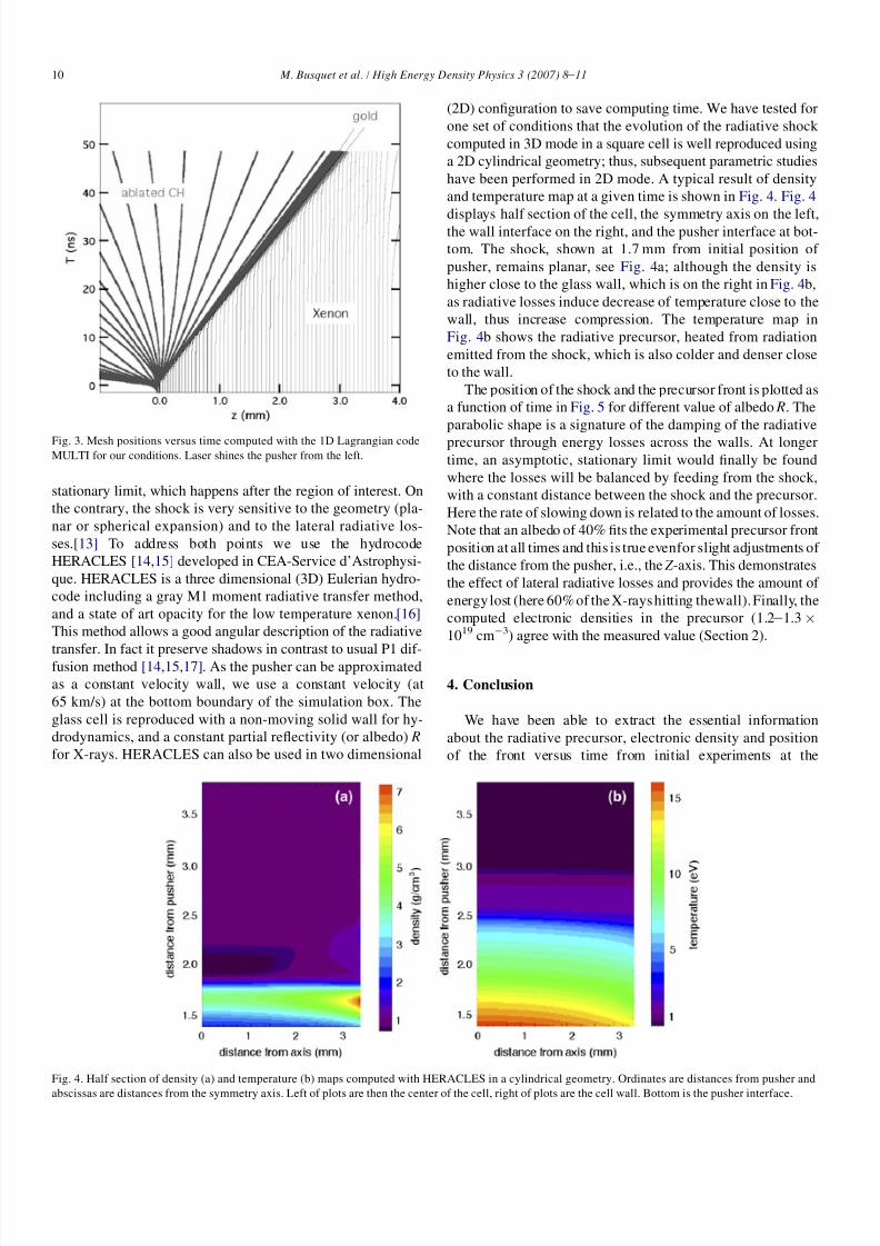
bright horizontal spot in Fig. 2 that we use as a time marker.
However, visible light going through the gas allows measure-
ment of the electron density by inverse bremsstrahlung absorp-
tion providing the precursor front position as a function of time,
displayed as black superimposed line in Fig. 2. The precursorregion is located at left of this line. The measured average inten-
sities in the averaging boxes displayed in Fig. 2 gives a trans-
mission of 70% in the precursor region compared to the
transmission in the unperturbed gas. With the transverse internal
dimension of the glass cell equal to 0.69 mm, we infer an elec-
tronic density of 1.1Â 1019 cmÀ3Æ 15%.
3. Numerical simulations and comparison with
experiment
We use the 1D Lagrangian hydrocode MULTI, [12] includ-
ing detailed physics (laser absorption, realistic ionization andEOS, non linear thermal conduction), to perform simulations
of the laser ablation of the pusher using the experimental
conditions (foil thickness, laser intensity versus time, xenon
pressure). The pusher is accelerated by rocket effect with
a rear surface velocity V p of 65 km/s without any noticeable
velocity change for more than 50 ns after the laser pulse, see
Fig. 3. Note that in the experimental conditions the pusher ve-
locity is roughly proportional to the mean laser intensity I L,
thus the accuracy of the velocity inference is equal to the pre-
cision on I L. As an ionizing Marshak wave, the front velocity
is not very sensitive to the pusher velocity from the time the
shock is launched into the medium until it reaches the
Fig. 1. Schematic layout of the experiment. The target is made of
a 4Â 0.7 mm glass tube, filled with xenon at 0.2 bar, closed at one end by
a gold coated CH pusher. A green 2 W laser, with an astigmatic imaging,
transverse too the cell probes the electronic density.
Fig. 2. False color enhancement (b) of the experimental image (a) of the
streaked interferogram. Time increases vertically for 50 ns, and distance
from the pusher goes from left to right with an accuracy of the origin estimated
to be 0.2 mm. Total observed length is 4 mm. The bright horizontal line occurs
during the 0.35 ns laser pulse. On the raw data (a), fringes are clearly seen be-
fore the laser pulse, and blur shortly after it. Although with a small contrast
(65%), an unambiguous absorbing front is seen with a parabolic shape. Super-
imposed in the false color image (b) is the computed position of the precursor
front. Boxes are the averaging areas to measure the relative intensity throughthe precursor and through the unperturbed gas.
9 M. Busquet et al. / High Energy Density Physics 3 (2007) 8e11
8/3/2019 M. Busquet et al- Effect of lateral radiative losses on radiative shock propagation
http://slidepdf.com/reader/full/m-busquet-et-al-effect-of-lateral-radiative-losses-on-radiative-shock-propagation 3/4
stationary limit, which happens after the region of interest. On
the contrary, the shock is very sensitive to the geometry (pla-
nar or spherical expansion) and to the lateral radiative los-
ses.[13] To address both points we use the hydrocode
HERACLES [14,15] developed in CEA-Service d’Astrophysi-
que. HERACLES is a three dimensional (3D) Eulerian hydro-
code including a gray M1 moment radiative transfer method,
and a state of art opacity for the low temperature xenon.[16]
This method allows a good angular description of the radiative
transfer. In fact it preserve shadows in contrast to usual P1 dif-fusion method [14,15,17]. As the pusher can be approximated
as a constant velocity wall, we use a constant velocity (at
65 km/s) at the bottom boundary of the simulation box. The
glass cell is reproduced with a non-moving solid wall for hy-
drodynamics, and a constant partial reflectivity (or albedo) R
for X-rays. HERACLES can also be used in two dimensional
(2D) configuration to save computing time. We have tested for
one set of conditions that the evolution of the radiative shock
computed in 3D mode in a square cell is well reproduced using
a 2D cylindrical geometry; thus, subsequent parametric studies
have been performed in 2D mode. A typical result of density
and temperature map at a given time is shown in Fig. 4. Fig. 4
displays half section of the cell, the symmetry axis on the left,the wall interface on the right, and the pusher interface at bot-
tom. The shock, shown at 1.7 mm from initial position of
pusher, remains planar, see Fig. 4a; although the density is
higher close to the glass wall, which is on the right in Fig. 4b,
as radiative losses induce decrease of temperature close to the
wall, thus increase compression. The temperature map in
Fig. 4b shows the radiative precursor, heated from radiation
emitted from the shock, which is also colder and denser close
to the wall.
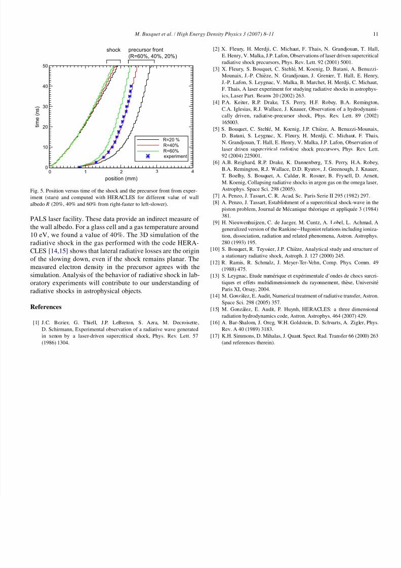
The position of the shock and the precursor front is plotted as
a function of time in Fig. 5 for different value of albedo R. The
parabolic shape is a signature of the damping of the radiative
precursor through energy losses across the walls. At longertime, an asymptotic, stationary limit would finally be found
where the losses will be balanced by feeding from the shock,
with a constant distance between the shock and the precursor.
Here the rate of slowing down is related to the amount of losses.
Note that an albedo of 40% fits the experimental precursor front
position at all times and this is true evenfor slight adjustments of
the distance from the pusher, i.e., the Z -axis. This demonstrates
the effect of lateral radiative losses and provides the amount of
energy lost (here 60% of the X-rays hitting thewall). Finally, the
computed electronic densities in the precursor (1.2e1.3Â
1019 cmÀ3) agree with the measured value (Section 2).
4. Conclusion
We have been able to extract the essential information
about the radiative precursor, electronic density and position
of the front versus time from initial experiments at the
Fig. 3. Mesh positions versus time computed with the 1D Lagrangian codeMULTI for our conditions. Laser shines the pusher from the left.
Fig. 4. Half section of density (a) and temperature (b) maps computed with HERACLES in a cylindrical geometry. Ordinates are distances from pusher and
abscissas are distances from the symmetry axis. Left of plots are then the center of the cell, right of plots are the cell wall. Bottom is the pusher interface.
10 M. Busquet et al. / High Energy Density Physics 3 (2007) 8e11
8/3/2019 M. Busquet et al- Effect of lateral radiative losses on radiative shock propagation
http://slidepdf.com/reader/full/m-busquet-et-al-effect-of-lateral-radiative-losses-on-radiative-shock-propagation 4/4
PALS laser facility. These data provide an indirect measure of
the wall albedo. For a glass cell and a gas temperature around
10 eV, we found a value of 40%. The 3D simulation of the
radiative shock in the gas performed with the code HERA-
CLES [14,15] shows that lateral radiative losses are the origin
of the slowing down, even if the shock remains planar. The
measured electron density in the precursor agrees with the
simulation. Analysis of the behavior of radiative shock in lab-
oratory experiments will contribute to our understanding of
radiative shocks in astrophysical objects.
References
[1] J.C. Bozier, G. Thiell, J.P. LeBreton, S. Azra, M. Decroisette,
D. Schirmann, Experimental observation of a radiative wave generated
in xenon by a laser-driven supercritical shock, Phys. Rev. Lett. 57
(1986) 1304.
[2] X. Fleury, H. Merdji, C. Michaut, F. Thais, N. Grandjouan, T. Hall,
E. Henry, V. Malka, J.P. Lafon, Observations of laser driven supercritical
radiative shock precursors, Phys. Rev. Lett. 92 (2001) 5001.
[3] X. Fleury, S. Bouquet, C. Stehle, M. Koenig, D. Batani, A. Benuzzi-
Mounaix, J.-P. Chieze, N. Grandjouan, J. Grenier, T. Hall, E. Henry,
J.-P. Lafon, S. Leygnac, V. Malka, B. Marchet, H. Merdji, C. Michaut,
F. Thais, A laser experiment for studying radiative shocks in astrophys-
ics, Laser Part. Beams 20 (2002) 263.
[4] P.A. Keiter, R.P. Drake, T.S. Perry, H.F. Robey, B.A. Remington,
C.A. Iglesias, R.J. Wallace, J. Knauer, Observation of a hydrodynami-
cally driven, radiative-precursor shock, Phys. Rev. Lett. 89 (2002)
165003.
[5] S. Bouquet, C. Stehle, M. Koenig, J.P. Chieze, A. Benuzzi-Mounaix,
D. Batani, S. Leygnac, X. Fleury, H. Merdji, C. Michaut, F. Thais,
N. Grandjouan, T. Hall, E. Henry, V. Malka, J.P. Lafon, Observation of
laser driven supercritical radiative shock precursors, Phys. Rev. Lett.
92 (2004) 225001.
[6] A.B. Reighard, R.P. Drake, K. Dannenberg, T.S. Perry, H.A. Robey,
B.A. Remington, R.J. Wallace, D.D. Ryutov, J. Greenough, J. Knauer,
T. Boelhy, S. Bouquet, A. Calder, R. Rosner, B. Fryxell, D. Arnett,
M. Koenig, Collapsing radiative shocks in argon gas on the omega laser,
Astrophys. Space Sci. 298 (2005).
[7] A. Penzo, J. Tassart, C. R. Acad. Sc. Paris Serie II 295 (1982) 297.
[8] A. Penzo, J. Tassart, Establishment of a supercritical shock-wave in the
piston problem, Journal de Mecanique theorique et appliquee 3 (1984)
381.
[9] H. Nieuwenhuijzen, C. de Jaeger, M. Cuntz, A. Lobel, L. Achmad, A
generalized version of the RankineeHugoniot relations including ioniza-
tion, dissociation, radiation and related phenomena, Astron. Astrophys.
280 (1993) 195.
[10] S. Bouquet, R. Teyssier, J.P. Chieze, Analytical study and structure of
a stationary radiative shock, Astroph. J. 127 (2000) 245.
[12] R. Ramis, R. Schmalz, J. Meyer-Ter-Vehn, Comp. Phys. Comm. 49
(1988) 475.
[13] S. Leygnac, Etude numerique et experimentale d’ondes de chocs surcri-
tiques et effets multidimensionnels du rayonnement, these, Universite
Paris XI, Orsay, 2004.
[14] M. Gonza´lez, E. Audit, Numerical treatment of radiative transfer, Astron.Space Sci. 298 (2005) 357.
[15] M. Gonzalez, E. Audit, P. Huynh, HERACLES: a three dimensional
radiation hydrodynamics code, Astron. Astrophys. 464 (2007) 429.
[16] A. Bar-Shalom, J. Oreg, W.H. Goldstein, D. Schvarts, A. Zigler, Phys.
Rev. A 40 (1989) 3183.
[17] K.H. Simmons, D. Mihalas, J. Quant. Spect. Rad. Transfer 66 (2000) 263
(and references therein).
R=60%
R=40%
R=20 %
experiment
position (mm)
0 1 3 420
10
30
40
20
50
t i m e ( n s )
shock precursor front
(R=60%, 40%, 20%)
Fig. 5. Position versus time of the shock and the precursor front from exper-
iment (stars) and computed with HERACLES for different value of wallalbedo R (20%, 40% and 60% from right-faster to left-slower).
11 M. Busquet et al. / High Energy Density Physics 3 (2007) 8e11