Embed Size (px)
Citation preview

M-1 GARANDTM 9-1005-222-12
PLUS SUPPLEMENTAL MATERIAL FROMTM 9-1005-222-35 and FM 23-5
Department of the Army Technical Manual
OPERATOR AND ORGANIZATIONALMAINTENANCE MANUAL INCLUDING
REPAIR PARTS AND SPECIAL TOOLS LIST
RIFLE, CALIBER .30 M 1RIFLE, CALIBER .30 M 1 C (Sniper's)
andRIFLE, CALIBER .30 M 1D (Sniper's)
M-1 GARAND
HEADQUARTERS, DEPARTMENT OF THE ARMY, 17 March, 1969

*TM 9 .1005 .222-12TECHNICAL MANUAL HEADQUARTERS, DEPARTMENT OF THE ARMYNo . 9-1005-222-12
Washington, D.C ., 17, March 1969
Operator and Organizational Maintenance Manual
RIFLE, CALIBER .30: M 1,M 1C (Sniper's), M 1D (Sniper's)
'This manual supersedes TM 9-1005.222.12P/2, 11 August 1965 in its entirety.
1
Editor ; Jeff LesemannAssistant Editor; Francois Rheault Artist ; Alan Longwith
This manual is current as of 2 December 1968
Paragraphs PagePREFACE 3INTRODUCTORY CHAPTER, "Origins and Development" 5
Chapter 1 . INTRODUCTIONSection I . General 1-1 .1-3 13
II . Description and data 1-4, 1-5 13
Chapter 2 . OPERATING INSTRUCTIONSSection l . Controls 2-1, 2-2 15
II . Operation under usual conditions 2.3 - 2-12 16III . Operation of materiel used in conjunction with major item . . . . 2-13,2-14 17IV . Operation unusual conditions 2-15 - 2-20 17
Chapter 3. SERVICE AND MAINTENANCE INSTRUCTIONSSection I . Service upon receipt of materiel 3-1, 3-2 19
II . Repair parts, special tools and equipment 3-3 - 3-5 19111. Lubrication instructions 3-6 20IV . Preventive maintenance checks and services 3-7 20V. Troubleshooting 3-8 21VI . Operators maintenance procedures 3-9 - 3-11 24VII . Organizational maintenance procedures 3-12 - 3-14 25
Chapter 4 . MAINTENANCE OF MATERIEL USED IN CONJUNCTIONWITH MAJOR ITEM 4-1 39
Chapter 5 . AMMUNITION 5.1, 5-2 41
Chapter 6 . DESTRUCTION OF MATERIEL TO PREVENT ENEMY USE 6-1 42
APPENDIX A. REFERENCES 42
APPENDIX B. ORGANIZATIONAL MAINTENANCE REPAIR PARTSAND SPECIAL TOOLS LIST
Section 1 . Introduction 4311. Basic issue items (Fig . 33,34) 46
III . Maintenance and operating supplies 46IV. Prescribed load allowance 47V. Repair Parts For :
Trigger housing assembly (Fig . 35) 48Barrel and receiver group (Fig . 36) 48Telescope, M84 (Fig . 37) 49Kit, winter trigger (Fig . 38, 39) 49
VI. Special Tools, test and support equipment (Fig . 33,34,40) . . . . 50
Appendix C. MAINTENANCE ALLOCATION CHARTSection I . Introduction 56
11. Maintenance allocation chart for Rifle, Caliber .30 Ml, M1C(Sniper's), and MID (Snipers) 57
ADDENDA SUPPLEMENTAL MATERIAL 58

m

TM9.1005-222-12Chapter 1
INTRODUCTIONSection I.' General
1 .1 . ScopeThese instructions are for use by the operator and organizational maintenance personnel . They
apply to Caliber .30 Rifles, Ml, M1C (Sniper's) and MID (Sniper's) .
1-2 . Forms and Recordsa. General. Refer to TM 38-750 (Army Equipment Records Procedure) for forms and records
required .b. Recommendations for Maintenance Manual Improvements . Report of errors,
omissions, and recommendations for improving this publication by the individual user isencouraged. Reports should be submitted on DA Form 2028 (Recommended Changes to DAPublications) and forwarded direct to :
Commanding GeneralU.S. Army Weapons CommandATTN: AMSWE-SMM-PRock Island, Illinois 61201
1-3 . Administrative StorageRefer to TM 740-90-1 for administrative storage .
Section II . DESCRIPTION AND DATA
1-4 . Descriptiona. General . The Rifles, Ml, M1C (Sniper's) and MID (Sniper's) (figs. 1, 10 and 11) are clip-
fed, gas-operated, air-cooled, semiautomatic shoulder weapons .b. Differences in Models .(1) The MlC has a telescope mounted to the receiver.(2) The MID has a telescope mounted to the barrel .(3) The M1C and MID also require a flash hider and a cheek pad .
1-5 . Tabulated Dataa. Rifle, M 1 .
Weight of rifle w/o equipment 9.5 lb. approx.Weight of rifle w/bayonet 10.5 lb . approx .Length of rifle 43 in.Length of barrel 24 in .*Muzzle velocity 2,750-2,800 fps*Maximum effective range 500 yd .*Maximum effective rate of fire (aimedrounds per minute) 16-24
*Number of cartridges in clip 8*Types of ammunition Ball, armor-piercing-incendiary,
tracer, blank, rifle grenade cartridge and dummyb. Rifles, M1C (Sniper's) and MID (Sniper's) .
Weight w/equipment (telescope, flash hider,gun sling, and cheek pad) 11.75 lb . approx .
Length of rifle w/flash hider, type T-37 46-1/8 in .*This information also applies to the M1C and MID Rifles .
1 3

Figure 10 U .S . Rifle, Caliber .30, M IC [Sniper's), with flush hider, M 2 . From the collection of BrV Douglas-
Figure I I . U.S . Rifle, Caliber .30, M 117 (Sniper's) wirh flash hider, T 37 .

TM9-1005-222-12Chapter 2
OPERATING INSTRUCTIONSSection 1. Controls
2-1 . GeneralThis section describes, locates, illustrates, and furnishes the operator with essential informa-
tion pertaining to the various controls provided to properly operate the materiel .
2-2 . ControlsRefer to table 2 .1 .
NOTE. COCK HAMMER BEFORE PLACING SAFETY ON .
Figure 1 2 . Controls .15

Table 2-1 . Controls
Item
(See fig . 12)
Purpose
Safety
To prevent accidental firing.Trigger
To release hammer to effect firing .Windage knob
To adjust lateral movement of rear sight .Elevating pinion
To adjust elevation of aperture .Clip latch
To hold clip in receiver until last round is fired .
Section 11. OPERATION UNDER USUAL CONDITIONS
2-3 . GeneralThis section contains instructions for the operation of the rifles under conditions of moderate
temperatures and humidity . Instructions for operation under unusual conditions are covered insection IV .
2-4 . Preparation for Firinga. Examine bore . Make certain it is free of powder fouling or corrosion.b . Check gas cylinder lock screw for secure installation .c . Check ammunition . Make certain it is clean and that it is of the proper type and grade .d . Cock the rifle and place the safety in safe position (fig . 12) .
2-5 . Service Before FiringPerform the before firing operations as indicated in table 3-3 .
2.6 . LoadingRefer to FM 23-5 .
2-7. ZeroingRefer to FM 23-5 .
2-S. Misfire, Hangfire, and Cook-offRefer to FM 23-5 and paragraph 2-9b, below .
2-9. Procedures for Removing a Round in Case of Failure to Firea. General After failure to fire, due to misfire, the following general precautions, as applicable,
will be observed until the round has been removed from the weapon and the cause of failuredetermined.
(1) Keep the weapon trained on the target and see that all personnel are clear of the muzzle .(2) Before retracting the bolt and removing the round, see that personnel, not required
for operation, are cleared from vicinity .(3) Make certain the round, removed from the weapon, is kept separate from other rounds
until it has been determined whether the round or weapon is at fault . If the weapon is determin-ed to be at fault, the round may be reloaded .b. Time Intervals. The definite time intervals for waiting, after failure of weapon to fire, areprescribed as follows : Always keep the round in the chamber for five seconds from the timea misfire occurs to insure against an explosion outside of the gun in event a hang-fire develops .If the barrel is hot and a misfire stops operation of the gun, wait five seconds with the roundlocked in the chamber to insure against hangfire dangers (a hangfire will occur within five secondsafter the primer is struck), then extract the round immediately to prevent cook-off . If the roundcannot be extracted within an additional five seconds, it must remain locked in the chamberfor five minutes because of the possibility of a cook-off. Also in the event the barrel is hot andmisfire occurs when attempting to resume firing after an intentional cessation of firing, the roundshould remain locked in the chamber for five minutes because of the possibility of a cook-off .
16

2-10. Service During FiringPerform the during firing operations as described in the operators preventive-maintenance
services (table 3-3) .
2 .11 . UnloadingRefer to FM 23-5 .
2.12 . Service After FiringPerform the after firing operations as described in the operator's preventive-maintenance
services (table 3-3) .
Section III. OPERATION OF MATERIEL USED IN CONJUNCTIONWITH MAJOR ITEM
2.13 . GeneralThe following materiel is not normally used continually . Therefore, it is necessary to protect
from weather and dampness in storage . Clean and lubricate materiel as required, whether inuse or in storage .
2-14. Equipmenta. Grenade Launcher, M7A3 and Grenade Launcher Sight, M15. Refer to FM 23-30.b. Bayonet-Knife, M5 and M5A 1 and Bayonet-Knife Scabbard, MBA 1 . Keep bayonet
in scabbard except when removed for training, inspections, cleaning, repair, or for use incombat or danger zones .
c. Winter Trigger Kit. Use the winter trigger kit only in extreme cold operation and onauthority of unit commander.
Section IV. OPERATION UNDER UNUSUAL CONDITIONS
2.15. GeneralReport any chronic failure of materiel resulting from subjection to extreme conditions (par 1-2) .
2-16. Operation in Extreme Colda. In climates consistently below 0°F, it is necessary to prepare the rifle for cold-weather opera-
tion. The rifle should be thoroughly cleaned wiith SD, dry cleaning solvent, and lubricated withLAW, weapons lubricating oil .b. Rifles should be free of moisture and excess oil . Moisture or too much oil on the working
parts will cause them to be sluggish in operation, or perhaps to fail completely .
c . Exercise moving parts through their entire range at required intervals . This movementhelps prevent parts from freezing in place and reduces effort required to operate them .d. Materiel not in use and stored outside must be protected with proper cover .
Note. Transferring weapon from cold to warm air may cause moisture to collect . If the weaponis brought into a warm room, allow it to reach room temperature before cleaning and lubricatingas required .
2-17. Operation in Extreme Heata. Hot, Dry Climates .
(1) The film of oil necessary for operation and preservation dissipates quickly in hot climates .Inspect the rifle, paying particular attention to all hidden surfaces such as bolt and lug, operatingrod and recess, cam surfaces and bolt locking recess in receiver, where corrosion might occurand not be quickly noticed .
(2) Perspiration from the hands contributes to rusting because it contains acids and salts .After handling materiel, clean, wipe dry, and restore the oil film using PL special, generalpurpose lubricating oil .
17

(3) Clean and oil the bore more frequently than usual .(4) Apply linseed o il. to wooden parts to prevent drying .
b. Hot, Damp, and Salty Atmosphere .(1) See a(1) and (2) above under hot, dry climates .(2) Inspect materiel frequently because of increased possibility of rust .(3) When material is active, clean and lubricate the bore and exposed metal surfaces more
frequently than prescribed for normal service .(4) Moist and salty atmosphere tend to emulsify oils and greases and destroy their rust-
preventive qualities. Inspect all parts frequently for corrosion .(5) When materiel is inactive, cover metal surfaces with a film of PL special, general
purpose lubricating oil .(6) Apply linseed oil to wooden parts to keep out moisture .
2 .18. Operation in Dusty or Sandy Areasa . Clean and lubricate the materiel more frequently in sandy or dusty areas . Exercise
particular care to keep sand out of mechanisms when carrying out inspecting and lubricatingoperations. Shield parts from flying sand with tarpaulins during disassembly and assemblyoperations.b. Before operating in sandy areas, remove lubricant from bolt, barrel and receiver, operating
rod, and trigger housing assembly, as they will pick up sand and from an abrasive which willcause rapid wear . Dry surfaces wear less than surfaces coated with lubricants contaminated withsand. Clean and lubricate all exposed parts after action is over .
2.19. Hand-Carried Fordinga . No special lubricaion is required before fording .b. Protect from water splashes .c. If immersion does occur, proceed as directed in paragraph 2-20 .
2.20. Maintenance After Immersiona. General. During hand-carried fording, water seepage into bolt, trigger housing, receiver,
and operating rod assembly will usually occur. It is advisable, therefore, that the service out-lined below be accomplished on all weapons submerged in water as soon as practical to preventdamage to the weapon .b. Procedures.
(1) After submersion in salt water, wash in clear water to remove corrosive salts .(2) Drain all trapped moisture and wipe dry .(3) Assemblies which require disassembly for proper lubrication must be disassembled, dried,
and lubricated as soon as possible .
Note. Items not authorized for operator disassembly/assembly must be cleaned by organiza-tional maintenance personnel .
CARTRIDGE CLIP -MENBARREL AND RECEIVER GROUP -
Figure 13. U.S . Rifle, Caliber .30, M 1. Major assembly group.18

TM9.1005.222.12Chapter 3
SERVICE AND MAINTENANCE INSTRUCTIONSSection I. Service Upon Receipt of Materiel
3-1 . Generala. When a new or reconditioned Rifle, Ml, M1C (Sniper's) or MID (Sniper's) is received,
it is the responsibility of the officer in charge to determine whether the materiel has beenproperly prepared for service by the supplying organization and to be sure it is in condition toperform its function .b. All basic issue items will be checked with the listing in appendix B .c . A record will be made of all missing parts, tools, and equipment, and of any malfunctions .
Corrective action should be initiated as soon as possible .
3.2 . ServicesRefer to table 3-1 for services performed on receipt of materiel .
Table 3 .1 . Service upon Receipt of materiel
Section II. REPAIR PARTS, SPECIAL TOOLS AND EQUIPMENT
3-3 . Tools and EquipmentTools and equipment issued with the Caliber .30 Rifles, M1, M1C (Sniper's) and MID (Sniper's)
are listed in the basic issue items list, appendix B .
3-4. Special Tools and EquipmentSpecial tools and equipment are listed and illustrated in appendix B .
3-5. Maintenance Repair PartsOrganizational maintenance repair parts are listed and illustrated in appendix B .
19
Step Action Reference
RIFLESNote . When new rifles are received, they are sealed in
vapor proof, volatile corrosion inhibitor (VCI) bags .They are packed two in a carton and five cartons in abox .
1 Remove carton from box and rifle from carton and bags .
2 Check for missing items . App B,Note . Items must agree with Basic issue items list . Sec II
3 Clean and lubricate bore and chamber . Par 3-11a and 3-6
4 Field strip and inspect for missing parts and FM 23-5proper assembly .
5 Clean and lubricate the following : Par 3-1 laLocking lugs of bolt and 3-6Bolt guidesCamming surfaces of operating rod
6 Perform "before operation" Table 3-3preventive maintenance checks and services .

Section III. LUBRICATION INSTRUCTIONS
3.6. 'Generala. Make certain all metal parts have been cleaned with SD, dry cleaning • solvent . Dry
thoroughly . Apply a light coat of preservative, PL special, general purpose lubricating oil, forabove 0°F, and LAW, weapons lubricating oil, for below 0°F . Apply a light coat of rifle greaseto the following surfaces :
(1) Locking lugs of bolt, operating lug, and recesses .(2) Bolt guide.(3) Cams on trigger and hammer .
b. Refer to table 3-2 for a listing of lubrication and cleaning materiels and stock numbersfor requisitioning purposes .
c. Refer to paragraph 2-16 thru 2-20 for specific lubrication instructions under unusualconditions .
Table 3-2 . materiels Required for Maintenance Functions
Federal stock number
8020-244-0153
7920-295-2491
6850-965-2332
6850-224-66566850-224-66576850-224-66585350-221-0872
6850-281-1985
9150-273-23899150-231-66899150-754-00638010-221-06119150-292-9689
7920-205-1711
Item
BRUSH, ARTISTS: metal, ferrule, flat, chisel edges, 7/16 Ig .exposed bristleBRUSH, CLEANING, TOOL AND PARTS: rd, 100 percenttampico fiber .CARBON REMOVING COMPOUND : (P-C- 111) (5 gal. pail)CLEANING COMPOUND, RIFLE BORE : (CR)2 oz. can6 oz. can1 qt. canCLOTH, ABRASIVE: crocus, ferric oxide and quartz, jean-cloth-backing, closed-coating. (CA)DRY CLEANING SOLVENT: (SD) (1 gal can)LUBRICATING OIL, GENERAL PURPOSE : (PL special)4 oz . can1 qt . canGREASE, RIFLE: (1 lb. can)LINSEED OIL, RAW: (I gal . can) (TT-L-00215)LUBRICATING OIL, WEAPONS : (LAW) for below zerooperations (1 qt. can)RAG, WIPING: cotton (50 lb . bale)
Section IV. PREVENTIVE MAINTENANCE CHECKS AND SERVICES
3.7. Preventive Maintenancea. Purpose . To assure maximum operational readiness the operator must perform certain
scheduled maintenance services at designated intervals . See basic preventive maintenance pro-cedures (1) thru (3) under b below, and table 3-3 .
b. Preventive Maintenance Performed by Operator .(1) Rust, dirt, grit, gummed oil, and water cause rapid deterioration of outer surfaces and
internal mechanisms . Exercise care to keep all surfaces clean and properly lubricated . Exteriorsurfaces of the weapon (or components) are not to be cleaned or polished with treated clothsor other commercial compounds .
(2) Tighten loose parts .(3) Every six months check to see if all modifications have been applied . Refer to DA
Pam 310-7 . No alteration or modification will be made except as authorized by modificationwork order.
20

Table 3.3. Preventive maintenance Checks and Services
Section V. TROUBLESHOOTING
3.8. GeneralRefer to table 3-4 for troubleshooting .
21
Z
Interval B-Before operation
A-After operationD-During operation
W-WeeklyOperatorDaily Org.
Item to be inspected Procedure ReferenceB D A W
1 1 - - - Ml, M1C, MID Hand cycle the action to insure binding is notpresent .
2 2 - - - Trigger housing assembly Actuate safety. Safety will not engage whenhammer is forward .
Fig. 12
3 3 - - - Barrel and receiver Actuate windage knob and elevatingpinion of rear sight group for properoperation . Aperture must retain positionagainst thumb pressure .
Fig. 12
4 4 - - - Barrel and receiver Check front sight for secure installation.5 - 5 - - Ml, M1C, MID Check gas cylinder lock screw for
secure installation.Note. Do not tighten lock screw whenweapon is hot .
6 - - 6 - M1, M1C, MID Clean chamber, bore, and all components . Par3-11a
7 - - 7 - MI, MIC, MID Lubricate . Par3.6

Table 3.4. Troubleshooting
Firing pin worn, damaged, ormovement restricted
Inadequate firing pin protrusion
Weak or broken hammer spring
Replace firing pin (8, fig . 36 ) .
Evacuate to direct supportmaintenance personnel .
Replace hammer spring(4, fig. 35) .
MALFUNCTION I
PROBABLE CAUSECORRECTIVE ACTION
OPERATOR
I
ORGANIZATIONAL
Failure to load Damaged clip
Replace clip .Improperly assembled receiver
Disassemble, and reassemblecomponents
correctly (refer to FM 23-5) .Failure to feed Weak or broken operating rod Replace spring (2, fig . 36) .
springBinding or damaged operating rod Evacuate to direct support
maintenance personnel .Bolt fails to close Dirty or deformed ammunition
Clean or replace ammunition .Cartridge case holding bolt out
Pull bolt to the rear and removeof battery
dirty or deformed cartridge .Dirty chamber
Clean chamber (par 3-1 la) .Extractor does not snap over rim
Clean bolt assembly and extractor Replace extractor (5, fig . 36 ) .of cartridge
recess (par 3-lla) .Frozen ejector spring and plunger Replace ejector (6, fig. 36 ).Restricted movement of or Evacuate to direct supportdamaged operating rod maintenance personnel .
Weak or broken operating rod Replace spring (2, fig. 36 ) .spring
Damaged receiver Evacuate to direct supportmaintenance personnel .
Failure to fire Bolt not in battery
See "bolt fails to close" .Defective ammunition
Follow procedures for misfires(refer to FM 23-5) .

Hammer damaged or broken
Short recoil
Gas cylinder lock screw looseGas cylinder lock not fully seated
Carbon or foreign matter in gascylinder or barrel port
Defective operating rod springGas cylinder not fully seated
Failure of clip to eject Broken or deformed latch spring
Evacuate to direct supportmaintenance personnel
Tighten lock screw (15,fig . 36 ) .Tighten gas cylinder lock
(16, fig . 36 ).Clean (par 3-1 la) .
,,,,,,
Replace if necessary(15, fig . 36) .
Replace spring (2 fig . 36).Remove and properly installgas
cylinder (figs. 22, 23)
Evacuate to direct supportmaintenance personnel .
Evacuate to direct support-maintenance personnel .
Replace extractor (5, fig . 36 ) .Remove cartridge case fig . 14 ) .
Replace ejector (6, fig . 36 ) .
Evacuate to direct supportmaintenance personnel .
Evacuate to direct supportmaintenance personnel .
Replace latch spring(27, fig . 36) .
Improper lubrication in coldweather
Unserviceable gas cylinder
Clean and lubricate properly(par 2-16) .
-,-,,,,,,,,,,,,
Failure to extract
Failure to eject
Unserviceable gas piston
Cartridge seized iii chamber
Damaged or deformed extractorRuptured cartridge caseShort recoilWeak, frozen or distorted
Remove cartridge and cleanchamber (par 3-11a) .
See "short recoil" . .-_„„„_,,,,,_--.
Failure of bolt to beheld rearward afterlast round is fired
ejector spring and plungerInsufficient . rearward movement
of boltDefective or broken operating
rod catchDefective operating rod .
See "short recoil" .
--------------------------

EXTRACTOR
Figure 14. Removal of ruptured cartridge case .
Section VI. OPERATORS MAINTENANCE PROCEDURES
3.9. Removal/Installation of Major Groups and AssembliesRefer to FM 23-5 . Also see fig . 13 and fig. 15 .
3 .10. Disassembly/Assembly Barrel and Receiver GroupRefer to FM 23-5 . Also see figs. 20 through 30 .
3 .11 . Cleaning, Inspection, and Repaira. Cleaning .
(1) General .(a) Immediately after firing, thoroughly clean bore with a bore brush saturated with CR,
rifle bore cleaning compound .(b) After cleaning with CR, run dry swabs thni the bore until the swabs are clean . Make
certain that no trace of burned powder or other foreign substances are left in bore . Then applya light coat of PL special, general purpose lubricating oil .
(c) Clean the chamber with a cleaning brush dipped in CR .(d) Clean all surfaces exposed to powder fouling (bolt face, chamber, piston area of
operating rod assembly and gas cylinder lock screw) with CR .
Note . This compound is not a lubricant . Wipe dry and oil all parts which require lubrication .
CAUTION. The use of abrasives, steel wool, wire brushes, or scrapers on the piston areaof the operating rod assembly will change critical dimensions that may cause the weapon tomalfunction and is therefore prohibited . The application of lubricants to this area is alsoprohibited .
(e) For general usage, SD, dry cleaning solvent, may be used to clean or wash greaseand oil from all parts of the rifle .
(2) General precautions in cleaning .(a) SD, dry cleaning solvent, is flammable and should not be used near an open flame .
Have fire extinguishers available when using this material . This solvent evaporates quickly andhas a drying effect on the skin . If used without gloves it may cause cracks in the skin ; in someindividuals, mild irritation or inflammation may bedevelop . Use only in well-ventiilated areas .
(b) The use of gasoline, kerosene, bezene (benzol) or high-pressure water, steam, or air,for cleaning the weapon is prohibited .
(c) Do not dilute CR, rifle bore cleaning compound . Do not add antifreeze . Store cleanerin a warm place. Shake CR well before using .
(3) Cleaning of sling and scabbard . Clean mildewed canvas by scrubbing with a drybrush . If water is necessary to remove dirt, it must not be used until mildew has been removed .Oil and grease may be removed by scrubbing with issue soap and water . Rinse well with waterand dry .
CAUTION. At no time is gasoline or any solvent to be used to remove oil or grease fromcanvas .
19
24

To prevent mildew, air canvas items frequently .(4) Cleaning. Clean with a dry cloth . Periodically rub raw linseed oil on wooden com-
ponents to prevent drying or the absorption of moisture .
CAUTION. Do not apply linseed oil to those surfaces next to the barrel . Application ofoil to these surfaces creates heavy smoking when the barrel is hot . This smoke will obscure theoperator's vision . Portions which swell due to high moisture content should be dried before ap-plying the linseed oil . Do not allow linseed oil to contact or remain on metal parts .b. Inspection. Refer to paragraph 3-7 .c . Repair . Turn rifle into organizational maintenance personnel for any necessary repair.
Section VII . ORGANIZATIONAL MAINTENANCE PROCEDURES
3.12. Removal/Installation of Major Groups and AssembliesRefer to FM 23-5 .
3-13. Disassembly/Assembly of Major Group and AssembliesRefer to figures 15 through 30, 35, 36 and 41 .NOTE. White dots indicate disassembly, and black dots indicate assembly .
3-14. Cleaning, Inspection, and Repaira. Cleaning.
(1) General . Refer to paragraph 3-11a for general cleaning procedures .(2) Removing carbon . On component parts which have a hard carbon residue it may be
necessary to clean these parts with P-C-111, carbon removing compound . Observe the follow-ing procedures when using P-C-111 .
WARNING. Avoid contact of P-C-111 with skin . If contact does occur, wash compoundoff thoroughly with running water . A good lanolin base cream is helpful if applied after washingoff compound. Recommend use of gloves and protective equipment .
(a)Using a suitable container, fill with fresh compound .(b) Before soaking a component in compound, remove all grease, dirt and oil as indicated
in paragraph 3-lla . Place parts to be cleaned in a container and make certain they arecompletely immersed.
(c) Soak for 2 to 16 hours as necessary . Remove parts and drain. Rinse with water orsolvent. To effectively remove carbon, brush with a stiff bristle brush (not wire) under runningwater.
(d) Wipe parts dry and lubricate (par 3-6) .b. Inspection and Repair .Refer to table 3-5 .
NOTE. For items not authorized at organizational maintenance level, evacuate to directsupport maintenance personnel .
Table 3-5 . Organizational Maintenance Functions
Warning: Before starting an inspection, be sure toclean the weapon. Do not actuate the trigger untilthe weapon has been cleared . Inspect the chamberto insure that it is empty, and check to see thatno ammunition is in position to be introduced .
25
iITEM
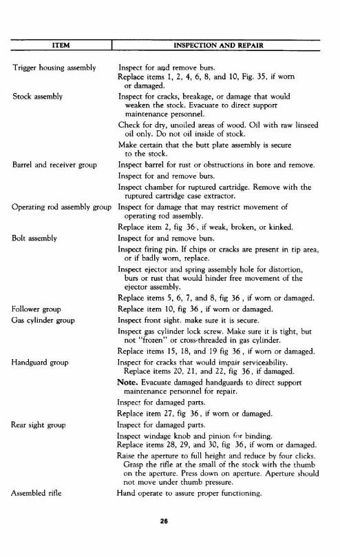
Inspect for and remove burs .Replace items 1, 2, 4, 6, 8, and 10, Fig . 35, if wornor damaged .
Inspect for cracks, breakage, or damage that wouldweaken the stock . Evacuate to direct supportmaintenance personnel .
Check for dry, unoiled areas of wood . Oil with raw linseedoil only . Do not oil inside of stock .
Make certain that the butt plate assembly is secureto the stock .
Barrel and receiver group
Inspect barrel for rust or obstructions in bore and remove .Inspect for and remove burs .Inspect chamber for ruptured cartridge . Remove with theruptured cartridge case extractor .
Operating rod assembly group Inspect for damage that may restrict movement ofoperating rod assembly .
Replace item 2, fig 36, if weak, broken, or kinked .Bolt assembly
Inspect for and remove burs .Inspect firing pin. If chips or cracks are present in tip area,or if badly worn, replace .
Inspect ejector and spring assembly hole for distortion,burs or rust that would hinder free movement of theejector assembly.
Replace items 5, 6, 7, and 8, fig 36 , if worn or damaged .Follower group
Replace item 10, fig 36 , if worn or damaged .Gas cylinder group
Inspect front sight . make sure it is secure .Inspect gas cylinder lock screw . Make sure it is tight, but
not "frozen" or cross-threaded in gas cylinder .Replace items 15, 18, and 19 fig 36, if worn or damaged .
Handguard group
Inspect for cracks that would impair serviceability .Replace items 20, 21, and 22, fig 36, if damaged .
Note. Evacuate damaged handguards to direct supportmaintenance personnel for repair .
Inspect for damaged parts .Replace item 27, fig 36, if worn or damaged .
Rear sight group
Inspect for damaged parts .Inspect windage knob and pinion for binding.Replace items 28, 29, and 30, fig 36, if worn or damaged .Raise the aperture to full height and reduce by four clicks .
Grasp the rifle at the small of the stock with the thumbon the aperture. Press down on aperture . Aperture shouldnot move under thumb pressure .
Assembled rifle
Hand operate to assure proper functioning .
Trigger housing assembly
Stock assembly
26
INSPECTION AND REPAIR

NOTE:UN000K HAMMERBEFORE DISASSEMBLING PIN
S
I
UNSEAT TRIGGER PIN .
04
figure 15 . Removal I installatiuun i ma)1rr groups and assemb4e,+ .
"me ~
.OCKING LUG
1
.-A
4
0
Figure 16 . Disassembly 1 assembly of trigger housing assembly (I of 4)
0

DISASSEMBLEJASSEMBLE TRIGGER
Figure 17. Disassembly / assembly of trigger housing assembly (2 of 4) .
HOUSINUI
am
1.11-1110 0"W"
DFSASSEMBLE ..•ASSEMBILE HAMMER SPRING ROUSING .HAMMER HELICAL COMPRESSION SPRING ANDHAMMER SPRING PLUNGER .
SPRING
PLUNGERI
i

4
ROTATE TRIGGER GUARD
UNSEATING EJECTOR
DISAS~LMhlF P,StiFS,'=_ : IPIGGLH GUARD
Figure 18 . Disassembly / assembly of truer housing assembly (3 of 4}.

DISASSEMBLE/ASSEMBLE CLIP EJECTOR
Figure 19. Disassembly I assembly of trigger housing assembly (4 of 4 ) .
DISCONNECT/ATTACHOPERATING ROD AND BOLT
Figure 20 . Removal / installation of bolt assembly .

DISASSEMBLY : PLACE TOOL IN BOLT AS SHOWNAPPLY PRESSURE AND TURN CLOCKWISE TOREMOVE EXTRACTORNOTE BE CAREFUL TO PREVENT SPRING ANDPLUNGER ASSEMBLIES FROM FLYING .
DISASSEMBLE/ASSEMBLE EXTRACIC' : .
OISASSEMBLE!ASSEMBLE EXTRACTORAND CARTRIDGE EJECTOR .
0
DISASSEMBLL .ASSEMBLE EXTRACTORSPRING PLUNGER .
Figure 21. Disassembly / assembly of bolt assembly .
ASSEMBLY. HOLD BOLT IN HAND WITH THUMB ONEXTRACTOR PLACF TOOL S,O GROOVE IS OVEREJECTOR AND COMPRESS EJECTOR AND SPRING INTOBOLT PUSH EXTRACTOR IN PLACE WITH THUMB
S
DISASSEMBLE+'ASSEMBLE FIRING PIN

(D NOTE- USE COMBINATION TOOL TO LOOSENGAS CYLINDER LOCK SCREW
DISASSEMBLEIASSEMBLE GAS CYLINDER LOCK SCREW
O
DISASSEMBLEIASSEMBLE GAS CYLINDER LOCK
0
S
Figure 22. Disassembly / assembly of gas cylinder group (1 of 2) .
DISASSEMBLE A':
ASH HIDER T37 FROMRFLE M IC M
LOOSEN GAS CYLINDER ASSEMBLY FROM BARREL .

Figure 23 . Disassembly / assembly of gas cylinder group (2 of 2) .
Figure 24 . Removal / installation of operating rod assembly .

DISASSEMBLE1ASSEMB
DEF ~
~ PIN
FOLLOWER ASSEMBLY
DISASSEMBLE/ASSEMBLE Fi;L.L
AF'v10
DISASSEMBLE FOLLOWERREMOVE!, NSTAL! . FOLL
7t5SEM8LY .
SL IDE FROM FOLLOWER .
Figure 25 . Disassernbiy I assembly of magazine fo&wer group (I of 2) .
I
DISASSEMBLE+ASSEMBLE BLILLE GJIUL
NOTE : DISASSEMBLY OFFOLLOWER ASSEMBLY ISNECESSARY ONLY IFREPAIR OR REPLACEMENTOF PARTS IS REQUIRED

DISASSEMBLEIASSEMBLEOPERATING ROD CATCH ASSEMBLY .
PIN -
kI∎
FOLLOWER SLIDE AND FOLLOWER DISASSEMBLED .
R
ARM-
OPERATING ROD CATCH ASSEMBLY DISASSEMBLED
Figure 26 . Disassembly / assembly of magazine follower group (2 of 2) .
-FOLLOWER SLIDE
FOLLOWER
ACCELLHATOR

LOOSEN/TIGHTFN RAND
L. > 4$0
DISASSL'v1E'. .= -ASSEMBLE FRONT HAND GUARD
0
0DISASSEMBLE/ASSEMBLE SPRING PIN
DISASSEMBLEASSEMBLE BAND
Figure 27, Disassembly / assembly of handguard group (l of 2) .
0

Figure 28. Disassembly / assembly of handguard group (2 of 2) .
REMOVE LATCH P1N, LATCH AND HELICALCOMPRESSION SPRING .
Figure 29. Disassembly / assembly of latch group.

0
NOTE : DEPRESS ELEVATING PINION (LEFT SID)PRIOR TO TURNING WINOAGE KNOB LOCKINGNUT
DISASSEMBLETASSEMBLE APERTURE
9
SEPARATE REAR SIGHT COVER FROM BASE .
Figure 30. D sassemhly 1 assembly of rear sight group .
DISASSEMBLEASSEMBLE ELEVATING PINION .
0
40DISASSEMBLE ;ASSEMBLE REAR SIGHT COVER AND BASE

TM9-1005-222-12Chapter 4
MAINTENANCE OF MATERIEL USEDIN CONJUNCTION WITH MAJOR ITEM
4-1 . GeneralRefer to table 4-1 .
Table 4-1. Maintenance of Equipment
39
Maintenance functionItem Operator's maintenance Organizational maintenanceGrenade Launcher, M7A3
Remove/install (fig. 31). Repair/replace.Clean/lubricate. Refer to TM 9-1005-234-14P
for authorized parts .Grenade Launcher Sight,
Remove/install (fig . 31) . Repair/replace .M15
Clean/lubricate . Refer to TM 9-1005-234-14Pfor authorized parts .
Bayonet-Knife,
Remove/install (fig 31) . Repair/replace .M5 and M5A1
Clean/lubricate . Refer to TM 9-1005-237-15Pfor authorized parts .
Scabbard, M8A1
Clean . Repair/replace .Refer to TM 9-1005-237-15P
for authorized parts .Winter trigger kit
Clean/lubricate . Repair/replace .Adjust trigger bar .Refer to appendix B for
authorized parts .

INSTALL/REMOVE GRENADE LAUNCHER
ALIGNING CLICK SPRI
TIPSTO MOUNTING PLATE NOTCHES .
FguYe 31. Materiel used irk c[rnj trg timi with majur items .
4 0

TM9-1005-222-12Chapter 5
AMMUNITION
Ammunition is loaded into 8 round clips, which are inserted, en bloc, into the magazine .(see fig . 32) .
5-1. TypesRefer to SC 1305/30 IL for identification of various types of ammunition .
5.2. Care, handling, Preservation, and DestructionRefer to TM 9-1300-206.
Figure 32 . Cart+idges and dip .
TM9-1005-222-12Chapter 6
DESTRUCTION OF MATERIEL TO PREVENTENEMY USE
6-1. Generala. Destruction of the rifle when subject to capture or abandonment in the combat zone, will
be undertaken only when in the judgment of the commander concerned such action is necessary .If destruction is resorted to, the equipment must be so badly damaged that it cannot be restoredto a usable condition in the combat zone either by repair or cannibalization . The reporting ofthe destruction of equipment is to be through regular channels .b. Priorities for destruction of repair parts are :(1) Firing pin(2) Extractor(3) Ejector(4) Hammer spring(5) Tigger(6) Safety
4 1

Appendix AREFERENCES
A. I . Publication IndexesConsult the following publication indexes frequently for the latest changes or revisions of
references and for new publications relating to material covered in this manual .
Index of Administrative Publications DA Pam 310-1Index or Army Films, Transparencies, GTA Charts, and RecordingsDA Pam 108-1Index of Blank Forms DA Pam 310-2Index of Doctrinal, Training and Organizational PublicationsDA Pam 310-3U.S. Army Equipment Index of Modification Work OrdersDA Pam 310-7Index of Supply Catalogs and Supply Manuals(excluding types 7, 8 and 9) DA Pam 310-6
Index of Technical Manuals, Technical Bulletins, Supply manuals(types 7, 8 and 9) Supply Bulletins, and Lubrication OrdersDA Pam 310-4
A-2 . FormsDA Form 2028, Recommended Changes to DA PublicationsDA Form 2407, Maintenance RequestDD Form 6, Report of Damaged or Improper ShipmentDA Form 9-79, Parts Requisition
A-3. Other PublicationsThe following explanatory publications pertain to this material .a. General
Accident Reporting and Records AR385-40Administrative Storage of Equipment TM 740-90-1Army Equipment Record Procedures TM 38-750Authorized Abbreviations and Brevity Codes AR 320-50Dictionary of United States Army Terms AR 320-5Military Symbols FM 21-30
b. Ammunition .Ammunition, General TM 9-1900Care, Handling, Preservation, and Destruction of AmmunitionTM 9-1300-206Disposal of Supplies and Equipment: AmmunitionAR 755-140-1Explosives and Demolition FM 5-25Malfunctions Involving Ammunition and ExplosivesAR 700-1300-8
c. Inspection and Maintenance .Cleaning of Ordinance Materiel TM 9-208-1Grenades and Pyrotechnics FM 23-30Operator, Organizational, DS and GS Maintenance Repair Parts andSpecial Tool Lists for Launchers, Grenade, M7A3 and M76TM 9-1005-234-14P
Organizational, DS, GS and Deposit Maintenance Repair Parts and Special ToolsList: Bayonet-Knife, M4, M5, M5A1, M6 and M7, and Bayonet-Knife Scabbard M8A1 TM 9-1005-237-15P
U.S . Rifle Caliber .30, M1 FM 23-5
d. Training.Military Training Management FM 21-5Techniques of Military Instruction FM 21-6
42

Appendix BORGANIZATIONAL MAINTENANCE REPAIR PARTS
AND SPECIAL TOOLS LIST
Section I. INTRODUCTION
B-1 . ScopeThis appendix lists basic issue items, repair parts, and special tools required for the perfor-
mance of organizational maintenance of the Rifles M1, MIC (Sniper's) and MID (Sniper's) .
B-2. GeneralThe Basic Issue Items, Repair Parts, and Special Tools List is divided into the following sections :a. Basic Issue Items List-Section II . A list of items which accompany the rifle and are
required by the operator/crew for installation, operation, or maintenance .b. Maintenance and Operating Supplies-Section III . A listing of maintenance and
operating supplies required for initial operation .c. Prescribed Load Allowance (PLA) .Section IV. A composite listing of repair parts,
special tools, test and support equipment having quantitative allowances for initial stockageat the organizational level .
d. Repair Parts-Section V. A list of repair parts authorized for the performance ofmaintenance at the organizational level in figure and item number sequence .
e. Special Tools, Test and Support Equipment-Section VI . A list of special tools, testand support equipment authorized for the performance of maintenance at the organizational level .
f. Federal Stock Number and Reference Number Index-Section VII . A list of Federalstock numbers in ascending numerical sequence, followed by a list of reference numbers,appearing in all the listings, in ascending alpha-numeric sequence, cross-referenced to theillustration figure number and item number .
B-3. Explanation of ColumnsThe following provides an explanation of columns in the tabular lists in Sections II through VI .a. Source, Maintenance, and Recoverability Codes (SMR) .(1) Source Code . Indicates the selection status and source for the listed item . Source
codes used are:
Code
ExplanationPRepair parts which are stocked in or supplied from the GSA/DSA, or
Army supply system, and authorized for use at indicated maintenancecategories .
P2Repair parts which are procured and stocked for insurance purposesbecause the combat or military essentiality of the end item dictates that aminimum quantity be available in the supply system .
MRepair parts which are not procured or stocked but are to be manufac-tured in indicated maintenance levels .
AAssemblies which are not procured or stocked as such but are made up oftwo or more units . Such component units carry individual FSN's anddescriptions, are procured and stocked separately and can be assembled toform the required assembly at indicated maintenance categories .
XParts and assemblies which are not procured or stocked and the mortalityof which is normally below that of the applicable end item or compo-nent. The failure of such part or assembly should result in retirement ofthe end item from the supply system.
X1Repair parts which are not procured or stocked . The requirement for suchitems will be filled by use of the next higher assembly or component .
43

X2 Repair parts which are not stocked . The indicated maintenance categoryrequiring such repair parts will attempt to obtain through cannibalization ;if not obtainable through cannibalization, such repair parts will be requisi-tioned with supporting justification through normal supply channels .
•
. . . . . . . . . Major assemblies that are procured with PEMA funds for issue initial onlyto be used as exchange assemblies at DSU and GSU level . Theseassemblies will not be stocked above DSU and GSU level or returned toDepot supply level .
(2) Maintenance Code.Indicates the lowest category of maintenance authorized toinstall the item . The maintenance level codes are :Code
ExplanationCCrew or operator•
. . . . . . . . . OrganizationalFDirect Support•
. . . . . . . . . General Support•
. . . . . . . . . Depot(3) Recoverability Code. Indicates whether unserviceable items should be returned for
recovery or salvage. Items not coded are expendable . The recoverability code is .Code
ExplanationRRepair parts and assemblies which are economically repairable at DSU
and GSU activities and are normally furnished by supply on an exchangebasis .
SRepair parts and assemblies which are economically repairable at DSUand GSU activities and normally are furnished by supply on an exchangebasis . When items are determined by a GSU to be uneconomicallyrepairable, they will be evacuated to a depot for evaluation and analysisbefore final disposition .
THigh dollar value recoverable repair parts which are subject to specialhandling and are issued on an exchange basis . Such repair parts are nor-mally repaired or overhauled at depot maintenance activities .
•
. . . . . . . . . Repair parts specifically selected for salvage by reclamation units becauseof precious metal content, critical materials, high dollar value reusablecasings, or castings .No Codeindicated-Part will be considered expendable .b. Federal Stock Number . Indicates the Federal stock number
assigned to the item and will be used for requisitioning purposes .c. Description. Indicates the Federal item name and any additional
description of the item required . The abbreviation "w/e" when used as apart of the nomenclature, indicates the Federal stock number includes allarmament, equipment, accessories, and repair parts issued with the item .A part number or other reference number is followed by the applicablefive-digit Federal supply code for manufacturers in parentheses .d. Unit of Measure (U/M) . A 2 character alphabetic abbreviation
indicating the amount or quantity of the item upon which the allowancesare based, e .g ., ft, ea, pr, etc.e. Quantity Incorporated in Unit. Indicates the quantity of the
item used in the functional group or assembly . A"V" appearing in thiscolumn in lieu of a quantity indicates that a definite quantity cannot beindicated (e .g., shims, spacers, etc.) .
44

f. Quantity Furnished with Equipment . Indicates the quantity ofan item furnished with the equipment (BILL only) .g. Component Application. Identifies the component application of
each maintenance or operating supply item (M&O supplies only) .k. 15-Day Organizational Maintenance Allowances .
(1) The allowance columns are divided into four subcolumns . In-dicated in each sub-column opposite the first appearance of each item isthe total quantity of items authorized for the number of equipments sup-ported. Subsequent appearances of the same item will have the letters"REF" in the allowance columns. Items authorized for use as required butnot for initial stockage are identified with an asterisk in the allowancecolumn.
(2) The quantitative allowances for organizational level ofmaintenance represents one initial prescribed load for a 15-day period forthe number of equipments supported . Units and organizations authorizedadditional prescribed loads will multiply the number of prescribed loadsauthorized by the quantity of repair parts reflected in the appropriate den-sity column to obtain the total quantity of repair parts authorized .
(3) Organizational units providing maintenance for more than 100of these equipments shall determine the total quantity of parts requiredby converting the equipment quantity to a decimal factor by placing adecimal point before the next to last digit of the number to indicate hun-dredths, and multiplying the decimal factor by the parts quantity authoriz-ed in the 51-100 allowance column . Example, authorized allowance for51-100 equipments is 12 ; for 140 equipments multiply 12 by 1 .40 or16.80 rounded off to 17 parts required .
(4) Subsequent changes to allowances will be limited as follows : Nochange in the range of items as follows : No change in the range of itemsis authorized . If additional items are considered necessary, recommenda-tions should be forwarded to Commanding General, Headquarters, U .S .Army Weapons Command, ATTN: AMSWE-SMM-SA, Rock Island, Il-linois 61201, for exception or revision to the allowance list . Revisions tothe range of items authorized will be made by the U .S. Army WeaponsCommand based upon engineering experience, demand data, or TAERSinformation.
1 . Illustration.(1) Figure Number . Indicates the figure number of the illustration in which the item
is shown.(2) Item Number. Indicates the callout number used to reference the item in the
illustration .
Note. Items called-out on illustration, but not listed, are for disassembly purposes only .
B-4. Special InformationIdentification of the usable on codes of this publication are :
Code
Used onNo Code . . . M1, M1C, and MIDAM1BM1CCMIDDM1 and MlCEM1 and MIDFM1C and MID
45

B-5. How to Locate Repair Partsa.When Federal stock number or reference number is unknown . :
(1) First. Using the table of contents determine the functional group or assembly, withinwhich the repair part belongs . This is necessary since illustrations are prepared for functionalgroups and assemblies, and listings are divided into the same groups .
(2) Second . Find the illustration covering the functional group or assembly to which therepair part belongs .
(3) Third . Identify the repair part on the illustration and note the illustration figure anditem number of the repair part .
(4) Fourth. Using the Repair Parts Listing, find the functional group or assembly to whichthe repair part belongs and locate the illustration figure and item number noted in the illustration .
b. When Federal stock number or reference number is known :(1) First . Using the Index of Federal Stock Numbers and Reference Numbers find the
pertinent Federal stock number or reference number . This index is in ascending FSN sequencefollowed by a list of reference numbers in alpha-numeric sequence, cross-referenced to theillustration figure number and item number .
(2) Second. Using the Repair Part Listing, find the functional group or assembly of therepair part and the illustration figure number and item number referenced in the Index of FederalStock Numbers and Reference Numbers .
B-6. Federal Supply Codes for Manufacturers
Section 11. BASIC ISSUE ITEMS LIST
46
(2) (3) (4) (5) (6) (7)Illustration
Federal Stock No . Description
Reference Number & Mfr . Code
Unit ofissue
Qtymc .in
unit
Qty.fum
ithequip.
(a)Fig.No
(b)ItemNo .
1005-556-4174
RIFLES, CALIBER .30, M1, M1C(SNIPER'S) AND MID (SNIPER'S)REPAIR PARTS : NONE AUTHORIZEDTOOLS AND EQUIPMENTBRUSH, CLEANING, SMALL ARMS : EA -- 1 33 1BORE 5564174 (19205)
1005-691-1381 BRUSH, CLEANING, SMALL ARMS : EA -- 1 33 2CHAMBER 7790582 (19205)
1005-791-3377 CASE LUBRICANT: 7790995 (19205) EA -- 1 33 71005-650-4510 CASE, SMALL ARMS CLEANING ROD: EA -- 1 33 6
7267754 (19204)1005-793-6761 HANDLE ASSEMBLY: CLEANING ROD : EA -- 1 33 3
7266115 (19204)1005-726-6109 ROD SECTION, CLEANING, EA -- 4 33 4
SMALL ARMS: 7266109 (19205)1005-654-4058 SLING, SMALL ARMS: 6544058 EA -- 1 34
(19205)1005-726-6110 SWAB HOLDER SECTION, EA -- 1 33 5
SMALL ARMS CLEANING ROD :7266110 (19204)
Code Manufacturer19200 . . . . . . Frankford Arsenal19204 . . . . . . Rock Island Arsenal19205 . . . . . . Springfield Armory

CALIBER .30 RIFLESM1, M1C (Sniper's)and MID (Sniper's)
Section III. MAINTENANCE AND OPERATING SUPPLIES
1005-288-3565
(1)
(2)
(3)Component application
Federal stock number
Description
SWAB, SMALL ARMSCLEANING: COTTON2V sq (1,000 IN PKG)5019316 (19204)
Section IV. PRESCRIBED LOAD ALLOWANCE
47
(1)Federal stock No .
(2)Description
(3)Qty .mc
to um pack
(4)15-day organizational
maint . allowance
Usable on code(a)1 5
(b)620
(c)2150
(d)51 .100
1005-313-9441REPAIR PARTS:SCREW - 2 2 2
1005-501-3667 PIN, SHOULDER, HEADED - -- 2 21005-554-6015 SAFETY, SMALL ARMS - -- -- 2 21005-554-6018 EJECTOR - -- -- -- 21005-554-6024 GUARD, HAND GUN
D -- 2 21005-554-6026 TRIGGER -- -- -- -- 21005-556-4245 GUARD, HAND GUN 2 2 21005-600-8616 EJECTOR, CARTRIDGE 2 21005-600-6818 PLUNGER, EXTRACTOR SPRING -- 2 2 21005.600.8868 APERTURE, SIGHT -- 2 2 21005.600.8879 PIN, FIRING -- 2 21005-600-8885 SPRING, HELICAL, COMPRESSION - 2 21005-600-8887 SPRING, HELICAL, COMPRESSION -- 2 2 21005-600-8891 SWIVEL, STACKING -- -- 2 2 21005-614-7568 SPRING, HELICAL, COMPRESSION -- -- 2 21005-731-2556 GUARD, HAND, GUN
C -- -- 2 2 21005-731-2737 KNOB -- 2 2 21005-819-4501 PIN, TRIGGER -- 2 2 21005-953-9504 EXTRACTOR, CARTRIDGE -- 2 2 21005-999-3400 PINION -- 2 2 35305-501-3678 SCREW, MACHINE -- - -- 2 25315-501-3668 PIN, STRAIGHT, HEADED -- -- 2 2 3
1005-288-3565TOOLS AND EQUIPMENT :SWAB, SMALL ARMS CLEANING -- 2 2 2
1005-556-4174 BRUSH, CLEANING, SMALL ARMS -- 2 3 61005-650-4510 CASE, SMALL ARMS CLEANING ROD -- -- 2 2 21005-654-4058 SLING, SMALL ARMS -- 2 2 31005-691-1381 BRUSH CLEANING, SMALL ARMS -- -- 2 2 31005-694-1662 BUFFER, CLEANING ROD -- -- 2 2 31005-726-6109 ROD SECTION, CLEANING, -- -- 2 2 2
1005-726-6110SMALL ARMS
SWAB HOLDER SECTION, SMALL -- -- 2 2 3
1005-791-3377ARMS CLEANING ROD
CASE, LUBRICANT 2 2 21005-793-6761 HANDLE ASSEMBLY -- -- 2 2 21240-763-1596 CASE, TELESCOPE -- -- 2 2

Section V . REPAIR PARTS LIST(1)
Source maint .recov . code
(2)Federal stock No .
(3)Description
(4)Unitof
mean
(5)Qtyme inunit
(6)15 day organizationalmaintenance alw
(7)Illustration
(a) (b) (c)
Reference Number & Mfr Code
Usable on Code(a)1 5
(b)6-20
(c)21-50
(d)51-100
(a)FigureNo
(b)ItemNo .
P O -- 1005-819-4501
REPAIR PARTS FOR :RIFLES, CALIBER .30, M1, M1C (SNIPER'S)AND MID (SNIPER'S)TRIGGER HOUSING ASSEMBLYPIN, TRIGGER : EA 1 * 1 2 3 35 17791367 (19205)
P O 1005-554-6026 TRIGGER: 5546026 (19205) EA 1 * * * 2 35 2P 0 -- 1005-600-8887 SPRING, HELICAL, COMPRESSION : EA 1 * 2 2 2 35 4
20 COILS, HAMMER 6008887 (19205)P 0 -- 5315-501-3668 PIN, STRAIGHT, HEADED : S, FL-FIL-HD, EA 1 2 2 3 B-2 -6
0.187 MAX DIA SHANK, Ya NOM LG UNDER5013668 (19204)
P 0 -- 1005-554-6015 SAFETY SMALL ARMS : EA 1 * * 2 2 35 8/8WP O -- 1005-554-6018 EJECTOR: CLIP 5546018 (19205) EA 1 * * * 2 35 10
P 0 -- 1005-614-7568BARREL AND RECEIVER GROUP :SPRING, HELICAL, COMPRESSION : 200 EA 1 2 2 36 2
---TOTAL COILS, OPERATING ROD 6147568 (19205)
BOLT ASSEMBLY 5546023P 0 -- 1005-953-9504 EXTRACTOR, CARTRIDGE : EA I * 2 2 2 36 5P 0 -- 1005-600-8616 EJECTOR, CARTRIDGE : EA 1 * * 2 2 36 6P 0 -- 1005-600-8618 PLUNGER, EXTRACTOR SPRING : EA 1 * 2 2 2 36 7
6008618 (19205)P O -- 1005-600-8879 PIN, FIRING: BOLT ASSY 6008879 (19205) EA 1 * * 2 2 36 8P 0 -- 1005-501-3667 PIN, SHOULDER, HEADED: FOLLOWER ARM EA 1 * * 2 2 36 10
5013667 (19204)P 0 -- 1005-313-9441 SCREW: GAS CYLINDER LOCK EA 1 2 2 2 36 15
7267797 (19205)

P 0 -- 5305-501-3678 SCREW, MACHINE : S, FIL-HD, NO . 10(0 .190) EA 1 2 2 36 18-32NF-2 X 0.700 MAX LG (STACKING SWIVEL)5013678 (19204)
P 0 -- 1005-600-8891 SWIVEL, STACKING: GAS CYLINDER EA 1 2 2 2 36 196008891 (19205)
P O R 1005-556-4245 GUARD, HAND, GUN: FRONT EA 1 * 2 2 2 36 20P 0 R 1005-554-6024 GUARD, HAND, GUN: REAR
D EA I * * 2 2 36 23P 0 R 1005-731-2556 GUARD, HAND, GUN: REAR EA I * 2 2 2 36 24
7312556 (19205)P O -- 1005-600-885 SPRING, HELICAL, COMPRESSION : EA 1 * * 2 2 36 27
6-7/8 COILS (LATCH) 6008885 (19205)P O -- 1005-731-2737 KNOB: WINDAGE EA 1 * 2 2 2 36 28P O -- 1005-999-3400 PINION: ELEVATING 11010364 (19204) EA 1 * 2 2 3 36 29P O -- 1005-600-8868 APERTURE, SIGHT : 6008868 (19204) EA 1 * 2 2 2 36 30
P O -- 1240-766-7454TELESCOPE, M84EYESHIELD: 7667454 (19200) EA 1 37 2
P O 1005-775-0364KIT, WINTER TRIGGERTRIGGER ASSEMBLY, WINTER: M5 EA 1 * 38 ' 1
7790808 (19205)P O -- 5305-990-6435 SCREW, TAPPING, THREAD FORMING : EA 2 * 38 2
7791415 (19205)P 0 -- 1005-010-5022 WASHER, HINGE RETAINING : TRIGGER EA 1 * 38 3
ASSEMBLY 7791237 (19205)P 0 -- 1005-778-0580 SAFETY, WINTER : EA 1 38 5
7790903 (19205)
1005-777-1369
MATERIAL REQUIRED FOR COLD WEATHERCLIMATESTHE FOLLOWING ITEM IS ISSUED OR REQ-UISITIONED ONLY BY SPECIAL AUTHORIZA-TION OF AREA COMMANDER.KIT, WINTER TRIGGER : FOR ARCTIC HANDWEAR EA5910520 (19204)
NOTE. INSTALLATION WILL BE PERFORMED BYDIRECT SUPPORT MAINTENANCE PERSONNEL .

Section VI. SPECIAL TOOLS, TEST AND SUPPORT EQUIPMENT111
Source mnint .recur . code
(2)Federal stock No .
(3)Description
(4)Unit
ofmeans
(5)Qtyinc inunit
(6)15 day organizationalmaintenance alw •
(7)Illustration
(a) (h) (c)
Reference Number & Mfr Code
Usable on Code(a)1 5
(b)&20
(c)21 50
(d)51 100
(a)FigureNo
(b)ItemNo .
C -- 1005-228-3536
TOOLS AND EQUIPMENTTOOLS AND EQUIPMENT AUTHORIZEDFOR UNIT REPLACEMENTSWAB, SMALL ARMS CLEANING : PG 2 2 2COTTON, 2Y SQ (1,000 IN PG)5019316 (19204)
C 1005-556-4174 BRUSH, CLEANING, SMALL ARMS: BORE EA -- 2 3 6 33 15564174 (19205)
1005-650-4510 CASE, SMALL ARMS CLEANING ROD: EA -- 2 2 2 33 67267754 (19205)
C -- 1005-654-4058 SLING, SMALL ARMS: EA -- 2 2 3 34C -- 1005-691-1381 BRUSH, CLEANING, SMALL ARMS: EA -- 2 2 3 33 2
CHAMBER 7790583 (19205)1005-726-6109 ROD SECTION, CLEANING, SMALL ARMS: EA 2 2 2 33 4
7266109 (19205)C 1005-726-6110 SWAB HOLDER SECTION, SMALL ARMS EA -- 2 2 3 33 5
CLEANING ROD: 7266110 (19204)1005-791-3377 CASE, LUBRICANT: 7790995 (19205) EA -- 2 2 2 33 71005-793-6761 HANDLE ASSEMBLY : CLEANING ROD EA -- 2 2 2 33 3
7266115 (19204)
0 1005-722-8907
ORGANIZATIONAL MAINTENANCE TOOLSAND EQUIPMENT (FOR ARMORERS USE)THE 15-DAY LEVEL IS NOT APPLICABLE .ENVELOPE: FABRIC, 2-BUTTON, 3H X 4-7/8W EA -- 1 -- -- -- 40 17228907 (19205)
0 4933-628-9700 REFLECTOR, GUN BARREL: EA -- 1 -- -- -- 40 27790138 (19205)
4933-652-9950 EXTRACTOR, RUPTURED CARTRIDGE CASE : EA 1 -- -- -- 40 37790352 (19205)

0~.rmmr-
-5
Figure 33 . Basic leaning tools.
Figure 34 . Web sling .
51
OIL 1~

e
Figure 35 . Trigger assembly - exploded view.
52
-10

Figure 35. Barrel and receiver group - explodesd view.

Figure 38 . Winter trigger kit - exploded view .
RI
ADAPTERNG- 10
Figure 39. Winter trigger kit, type T-36 .
Figure 37 . Telescope, M 84 .
54
2-
-3
Figure 40. Special tools and equipment .

3--
1
--
5, PIN STRAIGHT6 . CAP7 . PLUNGER8 SPRING9 BUTT PLATE
1 SCREW2 - PLATE3 - SCREW4 • BRACKET AND SPRING5-SCREW6 LEVEL ASSEMBLY7 - BODY
V
% -5
55
I MACHINE SCREW2 . BUTT STOCK SWIVEL3 . BUTT PLATE SWIVEL4 . BUTT PLATE ASSEMBLY
fig . sFigure 41- Si ock group - exploded view .
Figure 42. Grenade launcher sight, M 15 - exploded view .
10 STOCK SHOULDER13_v
11 MACHINE SCREW12 . SWIVEL STOCK13 . FFRRIJLE
12-C14 . STOCK
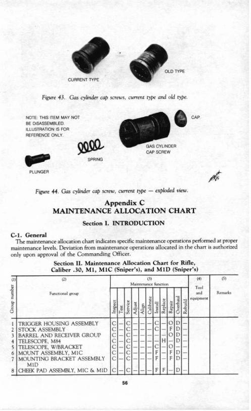
NOTE THIS ITEM MAY NOTBE DISASSEMBLED .ILLUSTRATION IS FORREFERENCE ONLY .
CURRENT TYPE
Figure 43 . Gas cylinder cap screws, current type and r.,ld type .
SPRING
PLUNGER
Figure 44- Gas cylinder cap screw, current type - exploded view .
Appendix CMAINTENANCE ALLOCATION CHART
Section I. INTRODUCTION
C- 1. GeneralThe maintenance allocation chart indicates specific maintenance operations performed at proper
maintenance levels . Deviation from maintenance operations allocated in the chart is authorizedonly upon approval of the Commanding Officer .
Section 11 . Maintenance Allocation Chart for Rifle,Caliber .30, MI, M IC (Sniper's), and MID (Sniper's)
L L) TYPE
56
CAP
A
L11
R1
Functional ,grcup
~
(3)Mamrcnancr function
14)
T~ In
er uipmenr
(5)
Remarks
H ¢
y
4cc va
vr7
r.oc
I TRIGGER HOUSING ASSEMBLY C - C' - - - - o 1) -2 STOCK ASSEMBLY C' - C - F D3 BARREL AND RECEIVER GROUP C - C - t7 D -4 TELESCOPE, M84 C - C - - - - H - D -5 TELESCOPE, WIBRACKET C - C - - - C - 0 - -6 MOUNT ASSEMBLY, MIC C . --- C - - - F - F D
7 MOUNTING BRACKET ASSEMBLY - C - - - F - F D -M1D
8 1 CHEEK PAD ASSEMBLY, M1C & M1D - - -- - F - D -

BS
5 . PIN STRAIGHT6-CAP7 PLUNGER8 SPRING9 BUTT PLATE
1 SCREW2 - PLATE3-SCREW4 BRACKET AND SPRING5 - SCREW6 - LEVEL ASSEMBLY7-BODY
w
55
1 MACHINE SCREW2 BUTT STOCK SWIVEL3 BUTT PLATE SWIVEL4- BUTT PLATE ASSEMBLY10 STOCK SHOULDER11 . MACHINE SCREW12 . SWIVEL STOCK13 .FFRRULE14 STOCK
Fig . 8Figure 41 . Stuck group - exploded view .
Figure 42- Grenade launcher sight, M 15 - exploded view .
17
13-%p

C-2. Maintenance FunctionsThe maintenance allocation chart designates overall responsibility for the maintenance function
of an end item or assembly . Maintenance functions will be limited to and defined as follows :
INSPECT
To determine serviceability of an item by comparing its physical, mechanical,and electrical characteristics with established standards .
TEST
To verify serviceability and to detect electrical or mechanical failure by use oftest equipment .
SERVICE
To clean, to preserve, to charge, and to add fuel, lubricants, cooling agents,and air.
ADJUST
To rectify to the extent necessary to bring into proper operating range .ALIGN
To adjust specified variable elements of an item to bring to optimum performance.
CALIBRATE To determine the corrections to be made in the readings of instruments or testequipment used in precise measurement . Consists of the comparison of two in-struments, one of which is a certified standard of known accuracy, to detectand adjust any discrepancy in the accuracy of the instrument being comparedwith the certified standard .
INSTALL
To set up for use in an operational environment such as an emplacement, site,or vehicle .
REPLACE
To replace unserviceable items with serviceable assemblies, subassemblies, or part .
REPAIR To restore an item to serviceable condition . This includes, but is not limitedto, inspection, cleaning, preserving, adjusting, replacing, welding, riveting, andstrengthening.
OVERHAUL To restore an item to a completely serviceable condition as prescribed bymaintenance serviceability standards using the Inspect and Repair Only asNecessary (IROAN) technique .
REBUILD To restore an item to a standard as nearly as possible to original or new condi-tion in appearance, performance, and life expectancy . This isaccomplished through complete disassembly of the item, inspection of all partsor components, repair or replacement of worn or unserviceable elements (items)using original manufacturing tolerances and specifications, and subsequentreassembly of the item .
C-3. Explanation of FormatPurpose and use of the format are as follows :a. Column 1, Group Number. . Lists group numbers, to identify components and assemblies.b. Column 2, Functional Group . Lists the noun names of groups and assemblies on which
maintenance is authorized.c . Column 3, Maintenance Functions . Lists the various categories of maintenance to be per-
formed on the weapon .d. Use of Codes . Explanation of the use of codes in maintenance function, column 3, is as
follows :
Code
Explanation
Code
ExplanationCOperator/crewOOrganizational
HGeneral SupportFDirect Support
DDepot
e. Column 4, Tools and Equipment. This column will be used to specify those tools and testequipment required to perform the designated function .f. Column 5, Remarks. Self-explanatory .Note: Columns not utilized are considered not applicable .
57

ADDENDASupplemental Material From TM 9-1005-222-35
Figure 45 . Gaping diameter of gas piston .
PLAIN RING GAGEI
BARREL GAS PORT
Figure 46. Gaging barrel diameter at gas port.
58
' "T, pi
BOLT ASSEMBLY
Figure 47 . Gaging firing pin protrusion .
Figure 48 . Reaming and gaping front interior of gas cylinder .
HHOULOER OrtMUST BE FLUSH CPI. VESF
ti TWO POSITIONS
1jW' APART .

CURRENT DESIGN
SERVICEABLE
PLUG PROTRUDES PLUG STFP PROTRUCI
///~
F////f~/q -GAGINGSURFACE
ORIGINAL DESIGN
CHECKING GAGE - RECEIVER UNSERVICEABLE
Figure 49. Gaping receiver .
59

REJECT LIMIT 0 .310
Figure 50 . Caging breech bore.
Figure _51 . Checking heads pace .
1 - MACHINE SCREW2 - GRIP . LH AND RH3 . SPRING PIN4 . LATCHING LEVER5 - HELICAL COMPRESSION SPRING6 BLADE ASSEMBLY
4-
W"I%Q
60
_ 1- 1
-2
45L& MIN . - 6 .5 MAX .(M 1C M 1D)
Figure 52 . Checking trigger pull .
Figure 53 . Bayonet knife, M 5A 1 - exploded view .NOTE: Bayonet knife M 5 differs internally, only, in position of helical spring .

Figure 54. Telescope, M 82 and mount assembly (M I C, Sniper only) .From the collection of Bill Douglas .
61
Figure 55 . Telescope . M 84 and mount assembly (M I D, Sniper only) .

CHEEK PAD-
-SCREWS--
a
CHEEK PAD ASSEMBLY - EXPLODED VIEW(M 1C (Snipers) and M $D [sniper's] only) .
DRILLING HOLES IN STOCK ASSEMBLY FOR INSTALLINGWOOD SCREWS
Figure 5 6 . 1nstaUationfremoVal of cheek pad assembly, Rifles M IC and M 1D {Sniper's}
REMOVEINST.aLL CHEEK PAD .
1~'GE
p,Ss
CHEEK PAD WITH LACE INSTALLED ON RIFLE . M 1COR MID

MARKING LOCATION FOR U HILL .N G H01 ES DRILLING HOLES IN STOCK ASSEMBLY
Figure 57 . Installation of winter trigger bit .
Figure 58 . Installation of alternate winter trigger hit . Type T-36
WINTER TRIGGERASSEMBLY
WINTER TRIGGERINSTALLED ONSTAMPEDTRIGGER GUAHU
WINTER TRIGGER ASSEMBLY INSTALLED

By Order of the Secretary of the Army :W.C. WESTMORELAND,General, United States Army,Chief of Staff.
Official:KENNETH G. WICKHAM,Major General, United States Army,The Adjutant General.
DISTRIBUTION :To be distributed in accordance with DA Form 12-40, (qty rqr block no . 128) Organiza-
tional maintenance requirements for Rifles, Caliber .30 : Ml, M1C (Sniper's) and MID (Sniper's) .
64