Embed Size (px)
Citation preview

Bureau of Indian Standards
LVDC-Redefining Electricity First International Conference on Low Voltage Direct Current
New Delhi, India,
26 & 27 October 2015
InternationalElectrotechnicalCommission

Enabling an LVDC last mile distribution network
Dr Abdullah Emhemed
Prof Graeme BurtUniversity of Strathclyde
Department of Electronic and Electrical Engineering
Technology and Innovation Centre
Tel: +44 141 4447274
Glasgow-United Kingdom

Overview
1. Issues with an existing LVAC last mile network
2. Moving to an LVDC last mile: motivations
3. Moving to an LVDC last mile: challenges
4. Protection challenges
5. Protection solution
6. Conclusions

NOP
11/0.4kV
MV
Su
pp
ly
http://corrupteddevelopment.com/
1. Issues with existing LVAC last mile
Operates at 60 -70% of their limits with losses 3%
Under pressure to host more renewables
Benefit the least from load diversity
Under pressure to host more heat and transport demand
Become a bottleneck to connect further EV and heat pumps, power flow could reach up to 130%-150% in future UK system
Distribution networks are aging
Requires AC-DC conversion for supplying DC loads and hosting renewable
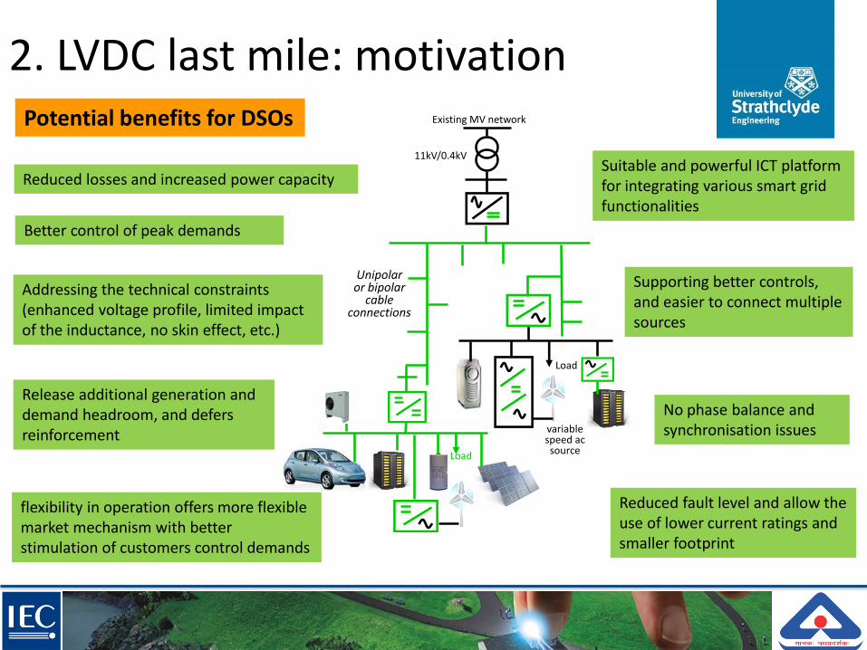
2. LVDC last mile: motivation
Load
Existing MV network
11kV/0.4kV
Load
variable speed ac source
Unipolaror bipolar
cable connections
Addressing the technical constraints (enhanced voltage profile, limited impact of the inductance, no skin effect, etc.)
Reduced losses and increased power capacity
Supporting better controls, and easier to connect multiple sources
flexibility in operation offers more flexible market mechanism with better stimulation of customers control demands
No phase balance and synchronisation issues
Better control of peak demands
Potential benefits for DSOs
Suitable and powerful ICT platform for integrating various smart grid functionalities
Reduced fault level and allow the use of lower current ratings and smaller footprint
Release additional generation and demand headroom, and defers reinforcement

Selected projects of DC in distribution
ScottishPower £15m ANGLE – DC project
KEPCO aims to replace a number of existing AC rural MV distribution networks supplying light loads by LVDC networks to save up to 5% of the total operating cost
Real rural LVDC network as a part of Finnish national Smart Grids research programme
Potential benefits for DSOs
2. LVDC last mile: motivation
P. Muutinen et al. “Experiences from use of an LVDC system in public electricity distribution” CIRED 2013

2. LVDC last mile: motivation
Load
Existing MV network
11kV/0.4kV
Load
variable speed ac source
Unipolaror bipolar
cable connections
Reduced energy waste and losses by reducing AC-DC conversion stages
More suitable for devices generate and consume DC (80% of todays load are DC)
Power converter interfaces are more mature and their associated costs are declining
Better control of energy leads to better market services and consumers cost savings
Potential benefits for end-users

IET LVDC Code of Practice
Section 4: Recognised standards of d.c. power distribution over telecommunications cabling
Section 5: Proprietary d.c. power distribution over telecommunications cabling
Section 6: Proprietary d.c. power distribution over proprietary cabling
Section 7: Proprietary d.c. power distribution over conventional single phase a.c. power supply cabling
Section 8: Proprietary d.c. power distribution over conventional 3-phase a.c. power supply cabling
2. LVDC last mile: motivation

If we are designing the first last mile today, would be an AC or DC?

3. LVDC last mile: challenges
Very limited experienceHuge investment in AC Interaction with existing AC gridLack of standards (topology, voltages, cable connections, etc.)international systematic approach on LVDC not yet providedLVDC benefits versus the costExisting LV protection is too simple and not capable of enabling the potential benefits afforded by LVDC last mile networks

4. Protection challenges
Characterisation of DC faults
DC protection for safety challenge
The requirement for high speed DC protection
Detecting and locating DC faults challenge
Protection against DC voltage disturbances
DC faults interruption challenge
Protection is top priority of any electrical distribution system
Does DC protection require more caution?
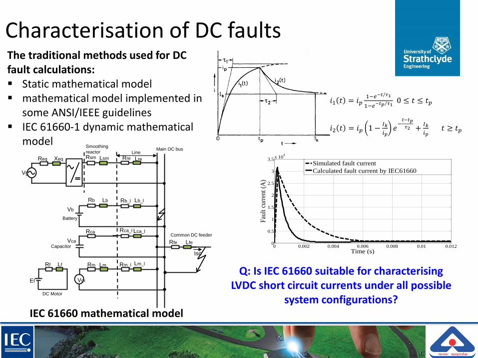
Characterisation of DC faults
0 0.002 0.004 0.006 0.008 0.01 0.0120
0.5
1
1.5
2
2.5
3
3.5x 10
4
Time (s)
Fau
lt c
urr
ent
(A)
Simulated fault current
Calculated fault current by IEC61660
Main DC bus
Rm Lm
Rca
Vg
Rsm Lsm LreRre
Common DC feeder
Isc
LfeRfe
Rb Lb
Battery
Vb
Capacitor Vca
Rca_l Lca_l
Rb_l Lb_l
Rm_l Lm_l
Vm
DC Motor
Ef
Rf Lf
XeqReq
Line
Smoothing
reactor
IEC 61660 mathematical model
The traditional methods used for DC fault calculations: Static mathematical model mathematical model implemented in
some ANSI/IEEE guidelines IEC 61660-1 dynamic mathematical
model
𝑖1 𝑡 = 𝑖𝑝1−𝑒 −𝑡 𝜏1
1−𝑒 −𝑡𝑝 𝜏1
0 ≤ 𝑡 ≤ 𝑡𝑝
𝑖2 𝑡 = 𝑖𝑝 1 −𝐼𝑘
𝑖𝑝𝑒−𝑡−𝑡𝑝
𝜏2 +𝐼𝑘
𝑖𝑝𝑡 ≥ 𝑡𝑝
Q: Is IEC 61660 suitable for characterising LVDC short circuit currents under all possible
system configurations?

DC protection for safety challenge
0V30V200V 120V400V 60V1500V
Band I (ELVDC)Band II (LVDC)
Comparable safety margin as for AC for direct contact (IEC60479) can be provided in 2-wire & 3-wire systems
Dangerous and could kill in case of direct contact
For <30V and in normal dry conditions for <60V, basic protection is not required for SELV and PELV systems
Comparable safety margin can be provided only with 3-wire system with grounded middle point
*The IEC 23E/WG2 workshop, “DC distribution system and consequences for RCDs”
Protection for safety : RCDs are not widely and commercially available for DC
Protection for equipment: detecting, locating, and interrupting DC faults are challenging

How does DC influence the existing earthing systems?
L+L-PE
L+
L-PE
0(N)
TN-S d.c. system
2-wire system
3-wire system
TN-C d.c. system
L+
L-PE
PEN
L+
L-
PE
L+
L-
0(N)
L+
L-PE
TN-C-S d.c. system
L+
L-
PE
L-
PE
0(N)
L+
L-
PE
0(N)
L+
L-
PE
L+
TT d.c. system IT d.c. system
3-wire DC systems can have lower touch voltages
DC protection for safety challenge

The requirement for high speed
4.8 5 5.2 5.4 5.6 5.8-1
0
1
2
3
4
Time (sec)D
C c
urren
t (k
A)
Fault3 (at 1km) Fault4 (at 2km)
Fault1(at 0km)
Fault2 (at 0.5km)
4.995 5 5.005 5.01 5.015 5.02 5.025-1
0
1
2
3
4
Time (sec)
DC
cu
rren
t (
kA
)
Fault1(at 0km)Fault2 (at 0.5km)
Fault3 (at 1km)
Fault4 (at 2km)
Transient DC
fault current
Steady state DC
fault current
2 - level VSC
F2 F3
F4
0.75kV LVDC last mile
Load1
Load2
NOP
RMU
11/0.4 kV 4.5% 500kVA
11kV AC system
1km
2km
F1
CB1
CB2
Power electronics poor short circuit capability
DC current circulates in the converter and other sensitive equipment
Protection systems need to be very fast to- prevent a high transient and steady state DC currents from
damaging equipment
- prevent the main converters from losing control and unnecessary tripping; and
- reduce the impact of post-fault power quality and stability

Detecting and locating DC faults challenge
The natural small DC line impedances can lead to more complexity for locating DC faults
Resistive faults hard to detect
Solutions
Using differential protection (time synchronisation issue)
Using signal processing techniques-based protection such as Travelling waves and Active Impedance Estimation (AIE)
0 200 400 600 800 1000 1200
-100
-50
0
50
100
150
200
Time (micro sec)
Cu
rren
t (A
)

5 6 7 8 9 10 11 12
0
0.5
1
1.5
Time (sec)
DC
Vo
lta
ge (
kV
) Post-fsult4 DC voltage
Post-fault1 DC voltage
Post-fault2 DC voltage
Post-fault3 DC voltage
Protection against DC voltage disturbances
Fast propagation of voltage disturbance
Sensitivity of AC/DC and DC/DC to voltage drops
Rapid DC voltage drop
Overvoltage on the DC side
caused by a line-to-earth fault on the AC side
Caused by the loss of the supply DC neutral/earth of a bipolar DC system
Post-fault transient overvoltage due the release of substantial energy stored in the
inductor ((1
2𝐿𝐼2) due slow protection
Voltage surge protection or fast protection that reduces the fault duration and magnitude are required

DC faults interruption challenge
DC arcs are more aggressive than AC
DC fault without zero crossing do not provide a natural low point to extinguish the fault arc
More complex techniques such as increased arc length and arc splitters are required

Mechanical breakers complied with IEC 60947-2
- LVAC Moulded Case CBs and Miniature CBs (magnetic trip units to be adjusted for DC)
- DC CBs equipped with permanent magnetic- DC CBs equipped with electronic trip units- Lower DC current and voltage ratings compared to
equivalent AC due to the higher risk of fire in DC
DC solid state breakers
- 900 times faster than LVDC mechanical breaker - On-state losses issues
http://www.electronicproducts.com
Using different converter topologies
DC hybrid breakers????
- Full bridge DC/DC chopper - full-bridge Modular Multi-level Converters
DC faults interruption challenge

Protection
functions
Relays C IED1 IED2 IED3 IED4
Current directions 1 0 0 0 0
Trip function - - - -
Blocking reverse current -
Reclosing function - - - - -
Protection
functions
Relays C IED1 IED2 IED3 IED4
Current directions 1 1 0 0 0
Trip function - - - -
Blocking reverse current -
Reclosing function - - - -
dc-dc48-12V
ac-dc
ACCB
F1
F2
LVDC last mile
AC grid
AC/DCSSCB
F3C
SSCB
SSCB
SSCB
dc-dcICT links
Elect links
Smart DC home
Communication-assisted
Fault detection and locations are based on DC current directions and magnitudes, and DC voltages
Using multiple IEDs
Using solid state circuit breakers for interrupting DC faults
Features
Multi-function DC protection for enabling an LVDC last mile
5. Protection solution

LVDC testing facilities

DC
Po
wer
So
urc
e
Lo
ad1
SSCB1
SSCB2 SSCB4
SSCB3
Loa
d2
LR2 2
L LR2 2
L
LR L
LR L
LR2 2
L LR2 2
L
IED4
IED3
IED2
IED1
V V
VV
V
IED5
SSCB5
Communication link
2I
2V
3I
3V
1I
1V
1C
1F
3C
2C4I
4V
3F
5I
5V2F
Feeder1
Feeder2
PCC
LVDC experiment circuit schematic
Validating the concept

Validating the concept
Start
The SSCB remains open
Reclosing function is performed and loads are
energised
The fault is temporary
End
Measure I (mag and dir) & Vdc at each IED
The fault is located at the PCC, the AACB is tripped and all downstream
µgenrators are tripped
The end user is faulted and its local SSCB directly operates
The fault is on the main feeder, and its IED trips the associated SSCB, and remotely trips all the
µgenrators connected to the feeder
The IED feeder with (+) current direction
takes the lead
I & V within the nominal limits
The converter IED current
direction is (+) and the feeder
IED is (-)
Any of the customers IEDs has a current
with (+) direction
YES NO
YES
YES
NO
NO YES
NO
Deployment of the Algorithm
using LabVIEW
Loads
Mimic LVDC
cablesCRIO: hardware-
software interface
Actual experiment setup

0 50 100 150 200 250 300 350 400 450 500 550 600 650 700
-100
-50
0
50
100
150
200
Time (s)
Cur
rent
(A
)
The supply (grid) DCfault contributionwith protection
The supply (grid) DC faultcontribution without protection
The DC fault contributions fromfeeder 1 and 2 without protection
The DC fault contributions fromfeeder 1 and 2 with protection
0 50 100 150 200 250 300 350 400 450 500 550 600 650 700-5
0
5
10
15
20
25
Time (s)
DC
vol
tage
s (V
)V1 at IED1
V2 at IED2
V4 at IED4
V5 at IED5
V3 at IED3
DC
Pow
er
Sourc
e
Loa
d1
SSCB1
SSCB2 SSCB4
SSCB3
Loa
d2
LR2 2
L LR2 2
L
LR L
LR L
LR2 2
L LR2 2
L
IED4
IED3
IED2
IED1
V V
VV
V
IED5
SSCB5
Communication link
2I
2V
3I
3V
1I
1V
1C
1F
3C
2C4I
4V
3F
5I
5V2F
Feeder1
Feeder2
PCC
Experimental results
100 150 200 250 300 350 400 450 500 550 600 650 700 750 800 850 900 950 10000
50
100
150
200
250
300
350
400
Time (s)
Cur
rent
(A
)
Fault current for F3 fault
Fault current for F2 fault
Fault current for F1 fault
6. Conclusions
LVDC distribution systems have the potential to bring benefits to future electricity grids
Replacing or energising an existing part of AC circuits using DC is still at very early stages and limited by practical technical solutions and lack of standards
The fund to LVDC projects is still limited to national levels
Protection and safety one of the major concerns
The developed fast acting DC protection has demonstrated more resilient performance for future LVDC networks

Thank you & Q