Embed Size (px)
Citation preview

Aalborg Universitet
Advanced LVDC Electrical Power Architectures and Microgrids
A Step toward a New Generation of Power Distribution Networks
Dragicevic, Tomislav; Vasquez, Juan Carlos; Guerrero, Josep M.; Skrlec, Davor
Published in:I E E E Electrification Magazine
DOI (link to publication from Publisher):10.1109/MELE.2013.2297033
Publication date:2014
Document VersionEarly version, also known as pre-print
Link to publication from Aalborg University
Citation for published version (APA):Dragicevic, T., Vasquez, J. C., Guerrero, J. M., & Skrlec, D. (2014). Advanced LVDC Electrical PowerArchitectures and Microgrids: A Step toward a New Generation of Power Distribution Networks. I E E EElectrification Magazine, 2(1), 54-65 . https://doi.org/10.1109/MELE.2013.2297033
General rightsCopyright and moral rights for the publications made accessible in the public portal are retained by the authors and/or other copyright ownersand it is a condition of accessing publications that users recognise and abide by the legal requirements associated with these rights.
? Users may download and print one copy of any publication from the public portal for the purpose of private study or research. ? You may not further distribute the material or use it for any profit-making activity or commercial gain ? You may freely distribute the URL identifying the publication in the public portal ?
Take down policyIf you believe that this document breaches copyright please contact us at [email protected] providing details, and we will remove access tothe work immediately and investigate your claim.
Downloaded from vbn.aau.dk on: November 24, 2021

Advanced LVDC Electrical Power
Architectures and Microgrids A Step towards a New Generation of Power Distribution Networks
Electrification Magazine, IEEE
Current trends indicate that worldwide electricity distribution networks are experiencing a
transformation towards direct-current (DC) at both generation and consumption level. This
tendency is powered by the outburst of various electronic loads and, at the same time, with the
struggle to meet the high set goals for share of renewable energy sources (RESs) in satisfying
total demand. RESs operate either natively at DC or have a DC link in the heart of their power
electronic interface, whereas the end point connection of electronic loads, batteries and fuel cells
is exclusively DC. Therefore, merging these devices into dedicated DC distribution architectures
through corresponding DC-DC converters arises as an attractive option not only in terms of
enhancing efficiency due to reduction of conversion steps, but also for having power quality
independence from the utility mains. These kinds of systems generally provide improved
reliability in comparison to their alternating current (AC) counterparts since the number of active
elements in DC-DC power electronic devices is smaller than in DC-AC converters. Besides that,
control design in DC systems is significantly simpler since there are no reactive and harmonic
power flows or problems with synchronization.
1. Historical Perspective: Return to DC
Present electrical power supply systems are the product of a long-term technological
development that basically started at the end of 19th
century. The trigger for its rapid uprising
was the invention of transformer, a first device that was able to transform AC voltages to

different values, and hence to keep the line losses at low levels, even when transmitting electric
power at long distances. Indeed, the transformer was the main odd for the victory of AC in the
famous “Battle of the Currents”, where Thomas Alva Edison and George Westinghouse publicly
confronted their newly proposed DC and AC power systems, respectively. The outcome of this
industrial war was strongly influenced by work of Nikola Tesla who invented a number of
breakthrough AC based devices and principles that kept its vital importance in industrial
applications up to present days. The final result was a global acceptance of AC as the
fundamental architecture for electricity generation, transmission and distribution. Shortly
thereafter, electricity became a publicly accessible good around the globe, hence triggering the
blossom of entire industry. This rapid development eventually brought up to another major
technological milestone: the invention of transistor. Being considered as one of the greatest
findings of twentieth century, the transistor was initially designed to lay the foundation for the
progress in computer and communications area. However, as a byproduct it has also enabled the
transformation of DC voltages, sparking a power electronics revolution. Nowadays, some fifty
years after its onset, power electronics is firmly established as an integral part of modern industry
which strongly underpins the new tendencies in power systems, one of which is the return of DC
in big style.
2. The Future of Integrated Power Distribution Systems: Compliance with
Smart Grid Objectives
It is a common belief that the energy, control and communications technologies have reached the
level of maturity which is sufficient to put forward a new power utility shift known as the Smart
Grid. The concept of Smart Grid was originally envisioned to stimulate the improvement of
electric power network in accordance with certain goals, such as:

Providing power quality for 21st century needs.
Operating resiliently against physical and cyber-attacks.
Accommodating all generation and storage options.
Enabling new products, services, and markets.
Optimizing assets and operating efficiently.
The concrete measures that should be taken in order to accomplish these objectives have been the
subject of intensified research over the past decade. This article explores the strategy which is
able to deal with all of them at the same time: a fundamental turnaround at the grassroots levels
of low voltage distribution systems from AC to DC architecture. In that sense, a particular DC
subsystem connected to a supreme AC distribution through dedicated DC-AC converter
automatically implies power quality independence from utility mains. Furthermore, it gives a
natural interface for modern electronic loads, as well as for most renewable energy sources and
energy storage systems like batteries. Possibility of islanded operation that makes the system
fully resistant to major blackouts in main grid is much more simple to design on DC due to
inexistence of synchronization problems and reactive power flows. Moreover, with proper
selection of nominal operating voltage, its efficiency will generally be higher than its AC
counterpart. Having these facts in mind, the authors envisage that these kinds of DC subsystems
will constitute the core of future distribution networks and that they will be gradually adopted in
applications such as DC homes, hybrid electric vehicle (HEV) charging stations, as well as
commercial and industrial facilities.
The foresight of the next generation distribution system that goes in line with aforementioned
discussion is depicted in Figure 1. It shows a number of DC powered subsystems connected to a
single synchronous AC system that include appliances in which DC is already utilized for years,

such as telecommunication systems, data centers, and DC renewable generation facilities.
However, it is the extension of DC to future appliances and to those that were traditionally
operating on AC backbone that will make a true difference. For instance, HEV charging station
formed around a common DC link has the ability of providing much faster recharging service to
connected vehicles than presently available AC chargers. Moreover, since the grid connection
may be realized by means of dedicated DC/AC converter, the grid support and power exchange
control at the associated point of common coupling (PCC) are straightforward. Substitution of
traditional AC architectures in favor of DC for the case of future households and commercial
buildings is expected to remarkably enhance their energy efficiencies since the major share of
their consumption is formed by devices that require a DC link in the interface point or in one of
the conversion stages. In this regard, appliances such as LED lighting, consumer electronics and
variable frequency drive (VFD) machines (refrigerators, heaters, air conditioners, washing
machines, etc.) may contribute to overall efficiency improvement by omitting one or several
DC/AC conversion stage(s). Another example for legitimate use of DC architecture is an
electrical power supply of a typical industrial factory facility where a potential for improving the
propulsion efficiency stems from a possibility to run a group of VFD motors from the common
DC link.
Today, residential DC architectures operating at 380 V are in the development stage and are only
a few steps away from the real-world implementation. Indeed, recent studies have roughly
estimated their cost-effectiveness, indicating up to 30% efficiency gain in comparison with
traditional low voltage AC. Electrical distributions of some of applications mentioned above are
addressed in more detail in following subsections, which are sequenced in line with their
growing nominal voltage.

2.1. Low Power Consumer Electronics
Battery is a “life vein” of consumer electronic devices such as MP3 players, cell phones, tablets,
digital cameras, laptop computers and others. Their entire electrical systems consist of a number
of DC-DC converter stages that are connected to battery terminals. These converters transform
the voltage to levels appropriate for fundamental loads such as display, processor, camera,
wireless module and other application adapted consumption (see Figure 2 for the typical
electrical layout of a modern smartphone).
Nowadays, lithium-ion polymer (Li-Po) battery cells are a common choice for consumer
electronics due to particularly high energy density and a convenient property that allows for high
degree of flexibility in the hardware design. However, unlike batteries from the previous
generations, a significant shortening of the lifetime or even hazardous conditions may occur if
lithium-based batteries are exposed to mistreatments such as high temperature or over-
charge/discharge operation. Therefore, a battery management system (BMS) whose main
function is recharge control, state of charge (SOC) and state of health (SOH) monitoring, has
become a constituent part of modern gadgets. In relation to required storage capacity, it is
generally possible to achieve a sufficient storage capacity for smartphones by utilizing a single
3.7 V Li-Po battery cell, whereas two to three paralleled cells are needed for tablets and digital
cameras. On the other hand, it is a common practice to assemble series-parallel cell arrangements
for supplying more demanding devices such as high-performance laptops. For these kinds of
packs, commercial BMSs often come with an integrated equalization circuit, which is necessary
for balancing the charge among the respective cells.
By referencing back to Figure 2, one may observe that DC-AC converter is the ultimate
conversion step towards the grid. With the aim of increase of energy efficiency, this conversion

stage may be avoided by using only a single stage DC-DC, given that there are readily accessible
DC sockets from dedicated DC power architecture. One example of such architecture, i.e. the
typical telecommunication power supply system, is presented in the next subsection.
2.2. Telecommunication Industry
The -48 V telecommunication power supply station is likely the best known example of a full-
scale DC distribution. Standard measure of reliability in this kind of system is five nines
(99.999%), whereas, for comparison, the usual requirement for the AC bulk power systems is
three nines (99.9%). There is a big difference in permissible downtime between the two, i.e. 5
minutes and 9 hours per year, respectively. The reason why such a high reliability may be
achieved in DC systems is a possibility for a direct connection of the central battery stack to the
common bus. This kind of strategy is, similarly like in the case of consumer electronics, also
popular in telecom industry.
In order to have high quality signal coverage over the large area, telecom companies are putting
more and more telecom stations into operation. Those of them that are built on remote locations
normally operate in islanded mode since they stand either too far from the AC utility mains or
have a consumption that is too low for performing cost-effective grid expansion. In that sense,
replacement of conventional diesel generators that require regular maintenance and refuel with
RESs as main energy sources emerges as an increasingly popular solution for modern
installations. The battery stack then has a dual role:
1. Back-up power and stabilization: Capacity of the battery is usually high enough to
provide long-term backup power and to ensure stability.
2. Smoothing the common bus voltage: Voltage transients in the common bus that arise
from fluctuating RES production and load profile are largely suppressed by the battery

polarization dynamics. It is worth mentioning that another DC storage technology, i.e. the
electrochemical double-layer capacitor (EDLC), is also often deployed for this short-term
power leveling purpose since it has an exceptionally high power density.
Typical electrical layout of a remote telecom DC distribution system based on RES is shown in
Figure 3. One may note that all components except of secondary batteries are connected to the
main bus through power electronic interfaces. Therefore, required voltage levels for electronic
loads are achieved by processing the battery voltage through dedicated point of load (POL)
converters. On the other hand, RESs are connected through either single or double converter
interfaces, depending on the type of the source. Nevertheless, their last conversion stage is
ordinarily based on a DC-DC converter with integrated bus-signaling control scheme which
determines the appropriate operating mode depending on the battery voltage (DC sources such as
PV panels and fuel cells can be connected through single DC-DC converter stage whereas in
case of AC sources such as small wind turbines, an intermediate DC link needs to be formed
using additional AC-DC converter). In general, there are two relevant modes in that sense:
constant power mode which implies operation under MPPT algorithms, and voltage regulation
mode where part of available energy from RES is dumped in order to regulate the charging of the
battery.
A distributed resolution of aforementioned control strategy gained a lot of popularity in industry
since it enables the plug’n’play feature for additional sources. For this reason, but also due to
inherent stability of these kinds of systems, the construction of customized DC renewable energy
parks for telecom stations was made possible in an ad hoc manner, by a simple buildup of the
system using commercially available modules. Nevertheless, this kind of approach may be

considered useful only for small scale electrical power supplies that do not require precise
control over the common bus voltage and are not anticipated for substantial future expansions.
2.3. Vehicular Technology: HEVs and Fast DC Charging Stations
The concept of electric car finds its roots at the end of 19th
century, where first vehicles were
developed largely relying on DC motor technology that was invented by Thomas Davenport in
1834. The accompanying industrial buzz resulted in several successful applications, such as
electric grid powered trolley systems for public transportation and coal mining. On the other
hand, motors in vehicles that required more freedom of movement such as taxis and passenger
cars were powered by electrochemical batteries. Electric vehicles (EVs) of that time had a
number of advantages over their gasoline and steam powered rivals such as significantly quicker
start time, and no issues associated with vibration, smell and noise. However, development of
inter-city road infrastructure in USA in early 20th
century highlighted the problem of their
limited range on one hand, while discovery of vast deposits of oil greatly reduced driving costs
of gasoline cars which soon completely took over the market.
Nevertheless, auxiliary 6 V DC electrical systems remained a vital part of road vehicles that
supplied power for electrical starters. The voltage was eventually increased to 14 V to support
newer and stronger engines with high performance starters and it was kept as the industry
standard up to date. Apart from ignition, the usage of electrical distribution eventually spread
also to power other appliances such as lighting, instrumentation and electric motor drives.
However, the propulsion of these vehicles remained based exclusively on internal combustion
engines (ICE) only until recent times.
A strong interest in EVs has been awakened again in the last few decades when concerns related
to reduction of fossil fuel reserves and a fact that vast greenhouse gas emissions come from
transportation sector became the main driving factor. A lot of academic and industrial effort has
been directed towards development of a more electric vehicle concept, giving birth to three main
groups of vehicular technologies; EVs, hybrid electric vehicles (HEVs) and fuel cell vehicles,
where the difference between them lies in the manner of power generation for vehicle
propulsion. So, the only source of power for EVs is electrochemical battery, while HEVs and
fuel cell vehicles are driven by the compound of a battery and ICE or hydrogen fuel cell,
respectively. Battery is still the major limiting factor for wider use of EVs, because power and
energy density in even the best technologies is not predicted to be competitive with those of
liquid fuels anytime soon. On the other hand, the technology of hydrogen fuel cell vehicles has
still not matured enough and although it offers good efficiency and practically zero emissions,
challenges related with hydrogen production and its storage within the vehicle keep restraining
its market penetration.
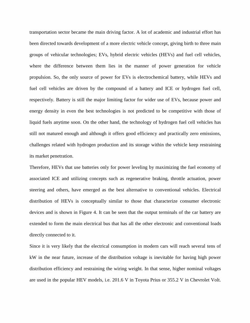
Therefore, HEVs that use batteries only for power leveling by maximizing the fuel economy of
associated ICE and utilizing concepts such as regenerative braking, throttle actuation, power
steering and others, have emerged as the best alternative to conventional vehicles. Electrical
distribution of HEVs is conceptually similar to those that characterize consumer electronic
devices and is shown in Figure 4. It can be seen that the output terminals of the car battery are
extended to form the main electrical bus that has all the other electronic and conventional loads
directly connected to it.
Since it is very likely that the electrical consumption in modern cars will reach several tens of
kW in the near future, increase of the distribution voltage is inevitable for having high power
distribution efficiency and restraining the wiring weight. In that sense, higher nominal voltages
are used in the popular HEV models, i.e. 201.6 V in Toyota Prius or 355.2 V in Chevrolet Volt.

By deploying power electronic converters, buses with other voltages can be realized, including
the classical 14 V bus which may serve for electrical supply of standard loads such as window
lifters, consumer electronic chargers or ventilation systems.
Another important prerequisite for the rapid increase in number of plug-in HEVs on the roads is
the construction of advanced EV charging infrastructure. A highly desirable feature of EV
charging stations in that sense is the ability to provide a re-charging procedure that is as similar
as possible to conventional petrol stations, as seen from the vehicle user. The main obstacle in
achieving this capability is the limitation of power extraction from conventional AC plugs of up
to 10 kW, which makes recharging process very slow and hence unattractive for public locations.
As a solution to this problem, fast charging directly from the station’s DC link has emerged as a
viable alternative. However, since it implies power extraction of up to 50 kW, there is a
legitimate concern about the adverse impact of large fleets of charging stations on utility mains.
Therefore, from the standpoint of present authors, it will be mandatory to use some kind of
dedicated energy storage system (ESS), at least for short-term power-leveling purposes. Diagram
of an EV fast charging station formed around a common DC link that uses a flywheel ESS for
the power balancing task is shown in Figure 5. Flywheel is selected here since it provides very
high power density and incomparably longer cycle-life than electrochemical batteries and hence
suits this kind of application much better, despite higher initial cost.
2.4. Enhancement of Conventional DC Power Distribution Architectures
The main factor contributing to high reliability and robustness of telecom systems, consumer
electronics and HEVs, i.e. direct connection of battery to the common bus, entails several major
drawbacks that come more into play in cases when more expandable and flexible DC systems are
required. The most prominent problems include mandatory rigid design of a battery pack,

decentralized charging that causes circulating currents, and inability to directly control voltage of
the common bus. In this regard, it is the connection of battery stack to a common bus via
dedicated DC-DC converter what distinguishes fully flexible systems from the applications
addressed in previous sections. This simple, yet effective topological change not only allows for
complete control over the battery recharging and common bus voltage, but also greatly facilitates
the system’s extensibility. However, even though the battery can now have a dedicated charger
that cancels out the circulating current effect, it cannot control the common bus and its own
voltage at the same time, hence other converters need to take care over the common bus voltage
regulation during the regulated charging process. Moreover, the effective capacity of the battery
is no longer seen at the main terminals, as it is now replaced by the several orders of magnitude
lower capacitance given only by the output filters of DC-DC converters. Therefore, control
design of bus regulating converters now becomes a much more challenging problem from
stability point of view. Additionally, a communication infrastructure between converters is often
adopted in order to coordinate and synchronize their actions in realizing functionalities such as
secondary or supervisory control, as depicted in Figure 6.
On the other hand, the controllability of a singular DC bus voltage results also in the
controllability of tie-line current flows towards other DC buses. Consequently, by adapting the
voltages of respective buses, it becomes possible to control complex DC power distribution
architectures. Functionally, such a structure can then be identified as microgrid (MG), a concept
that attracted considerable attention of the academic community over the past decade. The
following section looks back at the origin of MG and explores the possibilities on tailoring the
results from that research field to advanced DC power distribution architectures.
3. Changing the Energy Paradigm: Distributed Generation and Microgrids

Since the very beginning of the introduction of distributed generation, coordination among
various distributed generators (DGs) was recognized as a key prerequisite not only for the full
exploitation of their potential benefits, but also for avoiding negative impacts on utility. In that
sense, a MG concept emerged as one of possible resolutions for efficient integration of a growing
number of DGs scattered throughout the network. It is basically a small grid which gathers local
loads and DGs, and may operate in both grid-connected and islanded modes. Being an
independent entity which optimally coordinates local DGs and loads, MG was envisioned to
greatly reduce the number of nodes under the jurisdiction of distribution system operator and
hence to simplify the top level-communication infrastructure. This is so because internal
coordination of groups of final consumers and small DGs consolidated within the intelligent
MGs could be done independently from the distribution system and operator may hence only
consider power exchange with MG at the PCC.
Early MG efforts were largely focused on AC so as to line up with the existing power system
infrastructure. To that end, significant efforts focusing on improvement of current sharing, power
quality, stability, energy management and smooth mode transitions have been undertaken in
order to perfect and standardize the operation of inverter-based AC MGs. The topic has further
expanded, even to the level of a hierarchical control classification. Hence, AC MGs began to be
perceived as full-scale distribution systems compatible with the main utility. However, the initial
motivation has led to a somewhat misleading judgment that the standardization of MG topology
and control should be carried out literally following the guidelines imposed by the large AC
power systems. It is so due to fundamental differences between today’s technology and those at
the turn of twentieth century, the time when solid state power converters did not yet exist.
Indeed, the outcome of the famous “Battle of the Currents” which spawned the global direction

of power system evolution in favor of AC architecture could have been different if they did exist.
Nowadays, inspired by new trends in electricity production and consumption, as well as
remarkable technological improvements in power electronics, the same AC vs. DC debate takes
place again. However, this time it appears that the odds are on the side of DC, at least on the low
voltage level. Indeed, merging local DC devices into fully controllable and flexible DC MGs
arises as an attractive possibility for this paradigm shift.
4. DC Microgrids: Full-Scale Electricity Power Distribution Systems Adjusted to
Modern Trends
Advanced low voltage DC distribution systems for household and commercial appliances have
been under consideration for quite some time in both academia and industry. Recent comparative
analyses between performances of traditional AC systems and their DC counterparts have raised
a question about the most appropriate DC voltage level, which is to be adopted as a future
standard. However, as different types of modern consumer electronic appliances are operated on
distinctive voltage levels, it is generally agreed that future DC systems should not be formed
around one standardized bus, but of multiple buses with different voltages. In that sense, 380 V
is used as a rule for the high voltage bus since it is known to match the industry standard for
consumer electronics with the power factor correction circuit at the input. Moreover, this voltage
offers best efficiency gains in comparison to AC and is hence predicted to serve as the principal
distribution bus that supplies high demanding loads such as HEV chargers, washing machines,
rotating ESS etc. A number of lower voltage buses (48, 24 or 12 V) that power less demanding
loads like electronic devices and LED lighting and ventilation are foreseen to be built upon it
using dedicated power electronic interfaces. The structure that comprises a single high voltage
bus and a number of low voltage buses is depicted in Figure 7.

Nevertheless, when one considers a number of mutually interconnected DC subsystems, which is
preferably done on high voltage buses (i.e. 380 V), each one of them needs to have flexible
control over its internal voltage. This property may be achieved by sources whose converters are
designed for voltage support, i.e. voltage source converters (VSCs). If VSC converters are
programmed in a non-stiff manner, a number of sources may control the bus simultaneously.
This voltage regulating strategy is commonly referred to as the voltage-droop (VD) and is used
for primary control of DC buses MGs. Corresponding control law may be expressed as follows:
odMGrefDC iRvv , (1)
where DCv and MGrefv , are the common bus and reference voltage, respectively, oi is the output
current, whereas dR is the virtual resistance which defines the steady-state slope. As soon as it is
ensured that at least one converter operates in voltage regulating mode, other kinds of units may
be connected to the same bus. In that sense, it is desirable that RES exploit as much renewable
energy as possible, and hence their converters are run by the respective MPPT algorithms in
normal operating mode. This means that for given environmental conditions (sun and wind),
RES will follow the reference imposed by the algorithm, which is typically executed several
orders of magnitude slower than inner loop controllers. Therefore, RES can be considered as a
constant power (CP) source in dynamic sense. This point is depicted in Figure 8, where one may
see the operational principle of three converters connected to one common bus, with two
converters being operated in VD mode (with different slopes) and one converter in MPPT mode.
However, if the voltage of the bus is regulated exclusively by the law stated in (1), its deviation
from the reference value is unavoidable. This feature does not represent a significant problem in
autonomous applications with a single bus, but in case of multi-bus DC systems, voltage
deviations will be projected to uncontrolled tie-line current flows. In order to have a full control

over the MG, a higher control level that is able to assign correct voltage references to every bus
with respect to required current exchanges between them needs to be installed on top of primary
level.
4.1. Multi DC Microgrid clusters
A structure that incorporates both control levels, normally referred to as primary and secondary
control, is depicted in Figure 9. It should be noted that exclusively 380 V voltage buses are
designed to participate in inter-MG current exchange and only they are hence represented in the
figure. Tie-line current between two MGs can be regulated by imposing the appropriate voltage
drop between their buses. This voltage drop can be calculated by secondary current flow
controller which will generate positive or negative value (depending whether the current is
regulated to enter or exit the bus), and consequently cause increase or decrease of respective
common bus voltage. The extent to which units contribute can be actively regulated with
participation factors. Apart from enforced voltage drop, droop coefficient settings and load
variations also have an influence on steady-state voltage which may then in total considerably
deviate from the nominal value. For that purpose, a secondary voltage regulator can be deployed
in parallel with current flow controller to restore the deviation. Naturally, not every single bus
can be operated at the nominal value, but the best that can be done is to restore the average
voltage of all buses. Therefore, as depicted in Figure 9, two signals will form the outer voltage
reference designated for primary control loop, i.e. tv and sv .
It can be noted that secondary control in Figure 9 is designed in decentralized fashion, so that
every MG has a dedicated secondary controllers that are able to exchange information with its
neighbors others using communication infrastructure which is normally referred to as the
networked control system (NCS). Such an NCS may be realized by means of static averaging

calculation or using dynamic consensus algorithms. Both of aforementioned variations represent
a quite active research area.
Another control layer, referred to as the supervisory control or energy management system
(EMS), may be incorporated as well. Its functionalities are much more flexible and normally
comprise decision making mechanisms that aim to enhance the operational efficiency or to
govern the MG through different operational modes. One of the roles under the jurisdiction of
supervisory control is to determine required current exchanges between different MGs depending
on internal parameters such as SOCs of online ESS systems and/or energy available from RES.
Conclusion
Nowadays, world has to deal with a scenario where various electronic loads start to dominate the
overall consumption profile. HEVs are emerging as a worthy opponent to conventional vehicles,
and there is no end in sight for rising share of RES in total electricity production. Since DC
electricity is an integral part of a large portion of these modern technologies, there is a need for
reevaluation of the electrical distribution paradigm that was thought to be resolved in favor of
AC at the turn of 20th
century. In that sense, introduction of dedicated low voltage DC electrical
distribution systems that are able to bring the new technologies together and interface them with
AC utility in a more efficient and reliable manner is gradually becoming a reality.
This article examined electrical distributions of several modern DC-based industrial appliances,
and correspondingly, outlined the need for modification of existing DC architectures in order to
enhance their controllability and flexibility. A roadmap for this shift was proposed through the
application of DC MG technology, where several control levels have been examined. In line with
that, a layout of multi-bus DC MG with associated hierarchical control structure that is able to

regulate the current flows between different buses with respect to nominal voltage levels has
been presented.
For further reading
P. Fairley, “Edison’s Revenge: The Rise of DC Power,” MIT Technology Review, 2012. [Online]. Available: http://www.technologyreview.com/news/427504/edisons-revenge-the-rise-of-dc-power/. [Accessed: 21-May-2013].
M. Liserre, T. Sauter, and J. Y. Hung, “Future Energy Systems: Integrating Renewable Energy Sources into the Smart Power Grid Through Industrial Electronics,” Industrial Electronics Magazine, IEEE, vol. 4, no. 1, pp. 18–37, Mar. 2010.
S. Massoud Amin and B. F. Wollenberg, “Toward a smart grid: power delivery for the 21st century,” Power and Energy Magazine, IEEE, vol. 3, no. 5, pp. 34–41, 2005.
H. Farhangi, “The path of the smart grid,” Power and Energy Magazine, IEEE, vol. 8, no. 1, pp. 18–28, 2010.
B. T. Patterson, “DC, Come Home: DC Microgrids and the Birth of the ‘Enernet’,” Power and Energy Magazine, IEEE, vol. 10, no. 6, pp. 60–69, 2012.
G. AlLee and W. Tschudi, “Edison Redux: 380 Vdc Brings Reliability and Efficiency to Sustainable Data Centers,” Power and Energy Magazine, IEEE, vol. 10, no. 6, pp. 50–59, 2012.
D. Boroyevich, I. Cvetkovic, D. Dong, R. Burgos, F. Wang, and F. Lee, “Future electronic power distribution systems a contemplative view,” in 2010 12th International Conference on Optimization of Electrical and Electronic Equipment, 2010, pp. 1369–1380.
R. H. Lasseter, “MicroGrids,” in 2002 IEEE Power Engineering Society Winter Meeting. Conference Proceedings (Cat. No.02CH37309), vol. 1, pp. 305–308.
F. Katiraei, M. R. Iravani, and P. W. Lehn, “Micro-Grid Autonomous Operation During and Subsequent to Islanding Process,” IEEE Transactions on Power Delivery, vol. 20, no. 1, pp. 248–257, Jan. 2005.
J. M. Guerrero, J. C. Vasquez, J. Matas, L. G. de Vicuna, and M. Castilla, “Hierarchical Control of Droop-Controlled AC and DC Microgrids—A General Approach Toward Standardization,” IEEE Transactions on Industrial Electronics, vol. 58, no. 1, pp. 158–172, Jan. 2011.
H. Kakigano, Y. Miura, and T. Ise, “Low-Voltage Bipolar-Type DC Microgrid for Super High Quality
T. Dragicevic, J. Guerrero, J. Vasquez, and D. Skrlec, “Supervisory control of an adaptive-droop regulated DC microgrid with battery management capability,” Power Electronics, IEEE Transactions on, vol. 29, no. 2, pp. 695–706, 2014.

Annex - Figures:
-48 VDC remote telecom station
380 VDC pHEV charging station
380 VDC data center380 VDC
powered home
Distribution system
substation
AC transmission system
Grid rectifierGrid tied bidirectional
inverter
DC-DC
converters
+
+
+
+
-
-
-
-
DC renewable energy park
VFD industrial machinery
Flywheel
Multistage AC-DC
converters
+ -
Grid rectifier
LED street lighting
Grid inverter
Bi-directional AC-DC converters
380 VDC commercial
building
FIGURE 1. Vision of the future electricity distribution loaded with independent dc distribution
architectures.

DC-DC
DC-DC
DC-DC
DC-DC
AC-DC DC-DC
Wall socket, AC grid
Adapter
WiFi module
LCD panel Touch
screen control Camera
Charge control
3.7-20 Vdc bus
Battery pack
Optional cell charge
equalization(for series cell connections)
FIGURE 2. Block diagram of a typical modern smartphone.
DC-DC
DC-DC
Flywheel
Small wind turbine
PV array
Plug-in load sockets
Local control
Voltage meas.
Current meas.
DC-DC
Local control
Voltage meas.
Current meas.
Local control
Voltage meas.
Current meas.
AC-DC
AC-DC
DC-DC
DC-DC
DC-DC
POL converters AC-DC
Secondarybattery
FIGURE 3. Configuration of renewable energy based -48 V remote telecom power system.

High voltage storage system
Propulsion system
Bidirectional DC-AC
Electric machine 1
DC-DC
Low vo
ltage dc b
us
Conventional lo
ads
DC-AC
DC-AC
Steering system
AC-DC DC-DC
Air conditioning
pHEV charging station socket
Internal combustion
engine
Planetary gear unit
Electric machine 2
High volta
ge dc bus
FIGURE 4. Electrical distribution of HEVs.
DC-ACAC-DC
Grid converter
Flywheel converter
DC-DC
Flywheel
HEV
Local grid control
DC link
.
vBATiBAT
ω
Fast charge
controller
vDC
DSOcommands
.
Flywheel controlvDC
.
Grid
va,b,c
ia,b,c
va,b,c
ia,b,c
Electric machine
FIGURE 5. Diagram of a HEV dc fast charging station.

PV array Small wind turbine & generator
Battery bank Flywheel
Loads
Distributed generation
Common DC bus
Communication bus
Po
wer
lin
e
Mea
sure
men
ts Local control
level
Communication flow
Power flow
Higher control level:· Secondary control· Supervisory control
(EMS)
DC-DCDC-DC
DC-ACDC-DC
DC-AC
DC-DC
FIGURE 6. Flexible single dc bus dc system.

Com
munic
ation n
etw
ork
380 Vdc
Washing machine
48 Vdc
Air conditioner
Ceilingfan
Refrigerators
Electric Vehicles Flywheels
Consumer Electronics
Li-on batteries
To another DC bus
48 Vdc
24 Vdc
LED lights
DC-DC
DC-DCDC-AC
DC-DC
DC-DC
DC-AC
DC-DC
DC-DC
DC-DC
DC-AC
DC-DC
FIGURE 7. Structure of multi-bus DC microgrid.
vDC
vref,MG
vDC
io,MPPTio, VD 2
vDC
io, VD 1
iOP1 iOP2 iOP3
FIGURE 8. Primary voltage control of a flexible dc bus with distributed sources.

PWMgenerator( )vG s
DC Source 1
( )cG s
1dR
VDC1
VDC1
Voltage control Current control
Droop control
vref iref
io
PWMgenerator( )vG s
DC Source m
( )cG s
VDCm
Voltage control Current control
Droop control
Vref iref
io
VDCm
Primary Control
. . .
sec( )G s
Voltage secondary control
( )PFCG s
Power flow control
Participation factor
1i
im
Primary Control
i+1MG
Communication
iMG
i-1MG
Communication
MG
i bu
s
,1
ii
tie
,
1i
iti
e
MGsv
iMGv
outI
inI
tv
sv
iMGv
iMGv
mdR
380 VDC buses
DC-DC
DC-DC
DC-DC
DC-DC
DC-DC
To low voltage bus
To low voltage bus
To low voltage bus
Sup
ervi
sory
co
ntr
ol
*
1,outI
*
2,outI
*
3,outI
FIGURE 9. Multi-bus dc microgrid with primary&secondary loops and supervisory control.