Embed Size (px)
Citation preview
1
Exploration Science by the NLSI LUNAR Team: Lunar L2-Farside Missions, LUNAR Simulation Lab, Deployment of Lunar Radio Arrays, Drilling in the Regolith, Superconducting Bearings, &
Lunar Cement
Science associated with the Human Exploration of the Moon undertaken by the NASA Lunar Science Institute LUNAR1 Team
Director: Dr. Jack Burns, University of Colorado Boulder
Deputy Director: Dr. Joseph Lazio, JPL
The LUNAR team, in collaboration with Lockheed-Martin, is devising strategies for early robotic exploration and deployment of radio arrays (right) on the lunar farside using teleoperation from the Orion Crew Module (left).
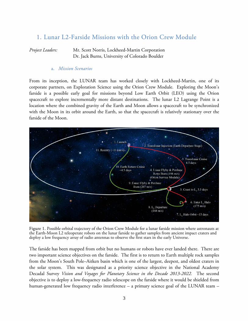
The LUNAR team is working with Honeybee Robotics to develop a gas-assisted drill tool (left) to thermally anchor next-generation retroreflectors to the lunar regolith. LUNAR team members have developed mirrors for future telescopes from lunar simulant cement (right).
1 The Lunar University Network for Astrophysics Research (LUNAR, http://lunar.colorado.edu) is funded by the NASA Lunar Science Institute (http://lunarscience.arc.nasa.gov) via Cooperative Agreement NNA09DB30A.

2
Summary
The Lunar University Network for Astrophysics Research (LUNAR) is a team of researchers and students at leading universities, NASA centers, and federal research laboratories undertaking investigations aimed at using the Moon as a platform for science. The LUNAR team is also exploring technologies that are likely to have a dual purpose, serving both exploration and science.
In collaboration with Lockheed-Martin, the LUNAR team is investigating human missions to the lunar L2 point that could be a proving ground for future missions to deep space while also overseeing scientifically important investigations. On an L2 mission, the astronauts would travel 15% farther from Earth than did the Apollo astronauts and spend almost three times longer in deep space. Such missions would validate the Orion Crew Exploration Vehicle’s life support systems for shorter durations, would demonstrate the high-speed reentry capability needed for return from deep space, and would measure astronauts’ radiation dose from cosmic rays and solar flares to verify that Orion provides sufficient protection, as it is designed to do. On such missions, the astronauts could teleoperate control landers on the lunar farside, which would obtain samples from the geologically interesting farside and deploy a lunar radio telescope. Such telerobotic oversight would also demonstrate capability for future, more complex deep space missions.
The LUNAR Simulation Laboratory at U. Colorado has been developed to mimic the temperature and photon radiation environment of the Moon’s surface over the course of a full lunar rotation. It has begun testing science equipment and deployment techniques using mini-rovers that are envisioned for both robotic and human exploration of the Moon. It serves as a facility to test other, Exploration-specific technologies, both for the Moon or other airless bodies such as NEOs.
Automated sensor deployment techniques are needed for surface missions in which instrument packages (either for Exploration or science) should or must be deployed at some distance from a lander. One option for deployment is a rover, but lower mass options, involving spring-and-pulley systems, are also being explored by the LUNAR team. Intended originally for lunar sensors, a spring-and-pulley system may be a useful technology for other low gravity environments.
Drilling in the lunar regolith requires a different approach than used on Earth, as the Apollo astronauts discovered. Such drilling may be required either for stability or thermal control. The LUNAR team, with partner Honeybee Robotics, has been exploring a gas-assisted pneumatic drill, which is demonstrating relatively deep penetrations with limited resource requirements.
In the thermal environment of the lunar night, and potentially on non-illuminated portions of larger asteroids, normal mechanical bearings and lubricants do not function well. The LUNAR team is exploring superconducting bearings, originally with the motivation for telescopes, useful also for communication equipment and other devices that require pointing or orientation control.
Regolith may prove to be an effective construction material. The LUNAR team has been exploring how modest equipment could be used to fuse lunar regolith into a concrete-like material, which could then be used for construction of large structures, without the expense of having to carry most of the material to the surface.
3
1. Lunar L2-Farside Missions with the Orion Crew Module Project Leaders: Mr. Scott Norris, Lockheed-Martin Corporation
Dr. Jack Burns, University of Colorado Boulder
a. Mission Scenarios
From its inception, the LUNAR team has worked closely with Lockheed-Martin, one of its corporate partners, on Exploration Science using the Orion Crew Module. Exploring the Moon’s farside is a possible early goal for missions beyond Low Earth Orbit (LEO) using the Orion spacecraft to explore incrementally more distant destinations. The lunar L2 Lagrange Point is a location where the combined gravity of the Earth and Moon allows a spacecraft to be synchronized with the Moon in its orbit around the Earth, so that the spacecraft is relatively stationary over the farside of the Moon.
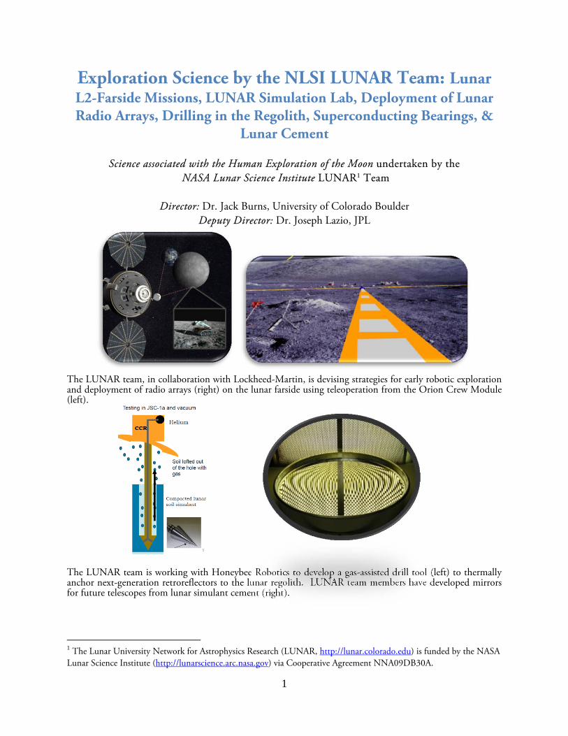
Figure 1. Possible orbital trajectory of the Orion Crew Module for a lunar farside mission where astronauts at the Earth-Moon L2 teleoperate robots on the lunar farside to gather samples from ancient impact craters and deploy a low frequency array of radio antennas to observe the first stars in the early Universe. The farside has been mapped from orbit but no humans or robots have ever landed there. There are two important science objectives on the farside. The first is to return to Earth multiple rock samples from the Moon’s South Pole–Aitken basin which is one of the largest, deepest, and oldest craters in the solar system. This was designated as a priority science objective in the National Academy Decadal Survey Vision and Voyages for Planetary Science in the Decade 2013-2022. The second objective is to deploy a low-frequency radio telescope on the farside where it would be shielded from human-generated low frequency radio interference – a primary science goal of the LUNAR team –

4
allowing astronomers to explore the currently unobserved Dark Ages and Cosmic Dawn. These early Universe observations were identified as one of three Science Objectives in the National Academy Decadal Survey New Worlds, New Horizons in Astronomy and Astrophysics: “Cosmic Dawn: Searching for the First Stars, Galaxies, and Black Holes.” The robotic lander and rover would be launched first on a slow but efficient trajectory to the Moon, to ensure that the rover is on its way before risking the crew launch. Next, three astronauts would be launched in an Orion spacecraft. If a heavy lift launch vehicle is developed, it would be capable of launching the crew directly towards the Moon. However, the mission can be performed by existing, smaller rockets, using a more complex launch arrangement. First, Orion would be launched to Low Earth Orbit on a rocket such as a Delta IV Heavy. Then, a modified Centaur upper stage would launch on a separate rocket such as an upgraded Atlas V, a second Delta IV, or an Ariane 5E contributed by the European Space Agency. Orion would dock to the Centaur stage in low orbit, and the Centaur would then boost Orion towards the Moon. Using either launch method, Orion would fly past the Moon for a gravity slingshot maneuver towards the L2 point. Orion would use its propulsion system to enter a halo orbit around the L2 point. From this vantage point 40,000 miles above the Farside of the Moon, Orion would have continuous line-of-sight visibility to both the entire Farside of the Moon, and the Earth. The LUNAR team has worked with Lockheed-Martin in developing a mission scenario in which astronauts, orbiting at the unique vantage point of L2, could remotely operate robots on the lunar surface to deploy a low frequency farside array of radio antennas. Astronauts will learn teleoperation techniques that will later be used to explore Mars from orbit. Astronauts would orbit the L2 point for about two weeks – long enough to operate a rover through the full length of a lunar day.
Figure 2. Remotely operated rover on the lunar farside (left). Deployed farside radio telescope array (right).

5
b. Exploration Benefits
The L2-Farside mission is a logical early step beyond low Earth orbit in advance of longer trips to more distant and challenging destinations like asteroids. Astronauts on an L2-Farside mission would travel 15% farther from Earth than the Apollo astronauts did, and spend almost three times longer in deep space. Each flight would prove out Orion’s life support systems for one-month duration missions before attempting a six month long asteroid mission. It would demonstrate the high speed reentry capability needed for return from the Moon or deep space – 40 to 50% faster than reentry from low Earth Orbit. The mission would measure astronauts’ radiation dose from cosmic rays and solar flares to verify that Orion provides sufficient protection, as it is designed to do. Currently the medical effects of deep space radiation are not well understood, so a one-month mission would Figure 3. L2-Farside mission using Orion. would improve our understanding without exposing astronauts to excessive risk. The L2-Farside mission also supports the development of key exploration technologies. For example, the Centaur stage used for the Earth orbit departure maneuver uses ultra-cold liquid oxygen and hydrogen propellants. Future human lunar landings and Mars missions would benefit from the ability to store these cryogenic propellants for weeks or months, instead of the current state of the art of several hours. The L2-Farside mission is an opportunity to demonstrate cryo-storage durations of a few days in an operational scenario rather than a test.
2. LUNAR Simulation Laboratory at the University of Colorado Project Leader: Dr. Jack Burns, University of Colorado Boulder
a. Description of the LUNAR Simulation Laboratory (LSL) With funding from NLSI, the LUNAR team has constructed a LUNAR Simulation Laboratory (LSL) at the University of Colorado to mimic lunar surface conditions during the day and night, and to test materials and material deployment that might be used for future space science and human exploration of the Moon. The core of the LSL consists of a vacuum chamber with a diameter of 1.1 meters and depth of 0.9 m. It can achieve a vacuum pressure of 10-8 torr. The simulated lunar surface plate can be thermally cycled to temperatures equivalent on the Moon between day (100 C) and night (-150 C). An
6
ultraviolet lamp is installed within the chamber to simulate the photon radiation environment of the Moon down to wavelengths of 100 nm. A video camera operates within the LSL to monitor experiments in real time. We can also continuously measure the thermal, mechanical, and electrical properties of test materials within the chamber.
b. Experiments with the LSL LUNAR has designed and carried out experiments to investigate the feasibility of using Kapton, a polyimide film, as the framework for a lunar telescope array. This low frequency radio telescope will be placed on the farside of the Moon to study the Dark Ages and Cosmic Dawn in the early Universe, low frequency radio emissions from the magnetospheres of Earth-like exoplanets, particle acceleration in the heliosphere of the Sun, and other astronomical phenomena. The telescope will be subjected to harsh conditions such as temperature variation from about -150 C to 100 C and ultraviolet radiation. The series of experiments conducted to date have investigated any changes in the Kapton's properties. Most recently, two experiments were performed each lasting one month. The vacuum chamber used was taken down to high vacuum (<10-7 Torr) and cycled down to -150 C for 24 hours and then up to 100 C for 24 hours. This was repeated for one month, simulating one lunar year.
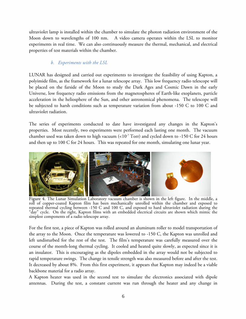
Figure 4. The Lunar Simulation Laboratory vacuum chamber is shown in the left figure. In the middle, a roll of copper-coated Kapton film has been mechanically unrolled within the chamber and exposed to repeated thermal cycling between -150 C and 100 C, and exposed to hard ultraviolet radiation during the “day” cycle. On the right, Kapton films with an embedded electrical circuits are shown which mimic the simplest components of a radio telescope array. For the first test, a piece of Kapton was rolled around an aluminum roller to model transportation of the array to the Moon. Once the temperature was lowered to -150 C, the Kapton was unrolled and left undisturbed for the rest of the test. The film's temperature was carefully measured over the course of the month-long thermal cycling. It cooled and heated quite slowly, as expected since it is an insulator. This is encouraging as the dipoles embedded in the array would not be subjected to rapid temperature swings. The change in tensile strength was also measured before and after the test. It decreased by about 8%. From this first experiment, it appears that Kapton may indeed be a viable backbone material for a radio array. A Kapton heater was used in the second test to simulate the electronics associated with dipole antennas. During the test, a constant current was run through the heater and any change in

7
resistivity was measured. Analyses of the results of this recent experiment are currently under way to determine if any degradation of the electrical properties of the embedded circuit occurred. The Kapton was electronically imaged under a microscope before and after thermal cycling to search for any evidence of delamination. Currently, the LUNAR team is constructing a small rover (10 x 10 cm2) with space-qualified components for use in the LSL. Once inside the chamber, the rover will be deployed to test strategies for unrolling the Kapton film, much as a robot on the Moon would. This experiment will help us to define the challenges of robotic Kapton deployment for a future lunar mission. We will be upgrading the LSL later in the year so that lunar simulant (regolith) can be placed within the chamber and serve as a more realistic surface from which we will conduct further experiments. The LUNAR team has also begun to work with Chris McQuin from the ATHLETE rover Mechanical Team at JPL to do thermal testing of actuator/joint components of this candidate lunar rover using the LSL at Colorado.
c. Exploration Benefits The Lunar Simulation Laboratory at the University of Colorado is designed to mimic the temperature and photon radiation environment of the Moon’s surface over the course of a full lunar rotation. It is an appropriate facility to test science equipment and deployment techniques that are envisioned for both robotic and human exploration of the Moon as well as other bodies such as NEOs. Thus, the LSL is relevant to advancing the Exploration goals of NASA.
3. Deployment Mechanisms for Surface Experimental Packages
Project Leaders: Dr. Robert MacDowall, NASA Goddard Space Flight Center Dr. Joseph Lazio, JPL
a. A Lunar Radio Array
During the Apollo missions, the astronauts deployed a series of small instrument packages, e.g., the Apollo Lunar Surface Experiments Package (ALSEP). The return of future robotic and crewed missions will be significantly enhanced if they are also capable of deploying small instrument packages, sometimes at distances from the lander; indeed, it is possible that automatic deployment of packages may be required as part of robotic precursor missions. One obvious deployment mechanism would be via a rover. We describe here an automatic deployment mechanism that is intended to be less massive, with lower power requirements. As an illustration, we consider the deployment of a novel antenna concept for use in studying the surface boundary exosphere of an airless body such as the Moon or a precursor to a future solar radio observatory.

8
Radio astronomy observations from the lunar surface provide access to data not available from Earth or satellites because of the lack of a significant lunar ionosphere, the stable 2-D surface on which to deploy antennas, and/or the radio quiet zone on the farside of the Moon. Each of these benefits plays a key role in some area of scientific interest. For example, radio images of redshifted 21-cm signals from neutral hydrogen originating from the very early Universe, the so-called Dark Ages before the first stars, require a large low-frequency radio array on the farside of the Moon, blocking the interference from terrestrial radio transmitters which would overwhelm the weak cosmological signal. Alternatively, imaging of solar radio bursts at frequencies below those observable from Earth’s surface would be possible for the first time with an array of ~50 antennas with a baseline of up to 1 km located on the lunar nearside. This concept has been proposed by the LUNAR team as the Radio Observatory on the Lunar Surface for Solar studies (ROLSS), shown in Figure 5, where the antennas and leads are metal deposited on rolls of Kapton® film, deployed in a Y-configuration. Finally, one or a few antennas on the lunar surface could be used to track the density of the lunar ionosphere by using the technique of riometry. A riometer is based on the simple physical principle that an ionized medium will not transmit radiation below its characteristic plasma frequency, which is based on the density of the medium. By measuring the cutoff frequency of a lunar ionosphere, a riometer uniquely determines the density of the ionized atmosphere of the Moon.
The first radio astronomy measurements from the lunar surface will necessarily be obtained by a pathfinder system, much smaller than the ROLSS array, to demonstrate feasibility of the system. We anticipate that deployment of two antennas (on Kapton® film) from a deployer mounted on the outside of a lander (e.g., Lunar Express, Odyssey Moon, etc.) is a reasonable approach. This deployer would require limited power and communication services from the lander, but would otherwise be independent of the lander and its primary science. The LUNAR team is actively seeking opportunities to deliver the ROLSS pathfinder (hereafter ROLSS-P) to the lunar surface. The technology has other substantial science-enabling capabilities for plasma environmental studies, subsurface geology, etc. If one can place a sheet of Kapton on the Moon, then one can measure surface charging, detection and quantification of a lunar ionosphere, dust detection, etc. (similar devices could be used on Mars). The deployer could also eject other systems, such as a ULF magnetotelluric system (R. Grimm), on either the Moon or Mars, or electrometers or biosensors or any distributed network of sensors to be located over 100-200m. LUNAR team members are working to develop an inexpensive ROLSS-P test unit, identify flight-qualified components that correspond to the components of the test unit, determine mass, volume, power, and cost requirements, demonstrate the statistical reliability of the deployer with hundreds of
Figure 5. Artist conception of ROLSS radio observatory on lunar surface. ROLSS has three 500 m arms with approximately 50 antennas total. Signals from each antenna are collected at the central hub and telemetered to Earth for processing of the radio images.

9
deployments on surfaces of various types (emulating different lunar surfaces), and document possible alternate approaches. This system will be capable of deploying other “packages,” representing small devices like electrometers or biosensors, thereby demonstrating a range of applications for the deployer.
This deployer system, shown in Figure 6, uses a spring deployed anchor to pull out and hold a double line, one end of which is attached to the leading edge of the film roll, the other to a small motor. In the model shown, the anchor and film canister is mounted on the outside of the lander. For deployment, the cover is opened, then the spring-driven anchor is released. Next, the motor begins pulling in the line, which sets the anchor and pulls out the film (schematic in Figure 8) with the deposited antennas. In order that the anchor not be a single point of failure, it is imperative that 1) the deployer launches it sufficiently far so that there are multiple opportunities for it to catch and hold, and 2) that the design of the anchor provides very high probability of “setting” on the various surfaces expected. For a flight mission, an optimized anchor, based on the expected surfaces at the landing site, would be designed and flown. Ideally, one wants a design that will collect sand or other debris or catch on small ridges in relatively smooth surfaces or catch on larger objects. For initial work, the team has been focusing on a “low profile scope with multi-scale teeth” (Figure 8), as that appears to be a robust design that will work under a wide variety of circumstances on a variety of surfaces. In addition to the issue of the anchor needing to set, there are also other potential risks related to large objects in the environment or non-optimal landing. A first mitigation for such issues would be
Figure. 6. Cartoon of film antenna deployment, which would use a mechanical spring to launch the anchor. Launching and setting an anchor first, providing a pulley point for the line from the motor to the leading edge of the film, is among the most reliable ways to deploy the antenna on the surface. Deployment stops when the “bead” on the line reaches the motor switch. Antennas and traces on film shown in Figure 3.
Figure 7. Schematic of two dipole antennas and traces (not to scale) on Kapton film. A total length of 50 m would be appropriate for low frequency solar radio burst detection in a pathfinder mode.
10
to make the deployer pointable in one or two dimensions. Clearly, adding one or more pointing motors, etc., will increase mass and other requirements, but the trade space for such options need to be examined thoroughly. Such a deployment mechanism would allow for instrument packages to be an augmentation of future New Frontiers missions. If efforts to build cost-effective lunar landers, such as Odyssey
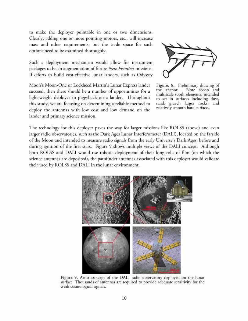
Moon‘s Moon-One or Lockheed Martin’s Lunar Express lander succeed, then there should be a number of opportunities for a light-weight deployer to piggyback on a lander. Throughout this study, we are focusing on determining a reliable method to deploy the antennas with low cost and low demand on the lander and primary science mission. The technology for this deployer paves the way for larger missions like ROLSS (above) and even larger radio observatories, such as the Dark Ages Lunar Interferometer (DALI), located on the farside of the Moon and intended to measure radio signals from the early Universe’s Dark Ages, before and during ignition of the first stars. Figure 9 shows multiple views of the DALI concept. Although both ROLSS and DALI would use robotic deployment of their long rolls of film (on which the science antennas are deposited), the pathfinder antennas associated with this deployer would validate their used by ROLSS and DALI in the lunar environment.
Figure 9. Artist concept of the DALI radio observatory deployed on the lunar surface. Thousands of antennas are required to provide adequate sensitivity for the weak cosmological signals.
Figure. 8. Preliminary drawing of the anchor. Note scoop and multiscale tooth elements, intended to set in surfaces including dust, sand, gravel, larger rocks, and relatively smooth hard surfaces.

11
b. Exploration Benefits The return of future robotic and crewed missions to the Moon will be enhanced considerably if they are also capable of deploying small instrument packages, sometimes at distances from the lander. In addition, as a risk reduction step, it may be necessary to undertake robotic precursor missions to some destinations. If so, it is possible that automatic deployment of packages such as proposed by the LUNAR team may be required as part of robotic precursor missions.
4. New Approaches to Drilling in the Lunar Regolith with Applications for Lunar Laser Ranging
Project Leaders: Dr. Douglas Currie, University of Maryland, College Park Dr. Kris Zacny, Honeybee Robotics
a. Robotic deployment of Retroreflector using gas-assisted drill
Many of the planned lunar science activities require drilling into the regolith, for example heat flow, core sampling as well as the optimal emplacement of the Lunar Laser Ranging Retroreflector for the 21st Century (LLRRA-21). New technologies have emerged since the Apollo missions but have not had the opportunity of being tested “in-situ”. LUNAR has supported the University of Maryland working with Astrobotics and Honeybee in order to define a new lunar laser ranging system as part of the Google Lunar X Prize (GLXP) program. This would consist of using the pneumatic drill developed by Honeybee on the Lander being developed by Astrobotics. Thus, this whole new
Figure 10. (Left and middle): Gas-assisted drilling tool developed by Honeybee Robotics with support from LUNAR. Astrobotics lander (right), including a Honeybee drill, are being proposed to deploy a next-generation lunar laser retroreflector on the lunar surface as part of the Google Lunar X-Prize competition.

12
concept may be tested in the real environment within the next few years. This program will provide information that will be of great value for missions like the Lunar Geophysical Network (a.k.a. ILN) as well as other missions to land on the surface of airless bodies.
b. Exploration Benefits The drilling technology developed to deploy a next generation Lunar Laser Ranging Retroreflector will be fundamental to construction and science activities as part of human exploration of the Moon. The Apollo astronauts demonstrated the difficulty of drilling and securing instruments to the lunar regolith using traditional tools. The drilling technology development supported by LUNAR will revolutionize human surface operations in the lunar environment.
5. The Design and Fabrication of Superconducting Bearings for Advanced Scientific Equipment on the Moon
Project Leaders: Dr. Peter C. Chen, Lightweight Telescopes, Inc. & Code 671, NASA Goddard Space Flight Center
Dr. Douglas M. Rabin, Code 670, NASA Goddard Space Flight Center Dr. Paul D. Lowman, Code 698, NASA Goddard Space Flight Center
a. Superconducting Bearings for Lunar Telescopes
As part of the efforts of the LUNAR team, research is being undertaken to address a challenge that is unique to the Moon. Lunar nights are long (15 days), and temperatures range from 100 K to 30 K inside shadowed craters. Pointing instruments on the Moon therefore require bearing systems that can position and track precisely over long time periods, preferably with no maintenance, and preferably do not fail with loss of power. The idea being developed involves using high temperature superconductors (HTS) as bearings in lunar telescopes. In a HTS-permanent magnet system the magnet is levitated above the HTS but is firmly held in place without physical contact and with no wobbling. The HTS bearing is passive, requires no power to maintain levitation, and has no mechanical wear. Our team is nearing completion in the development of a novel configuration HTS bearing system for telescopes. This design uses trunnion bearings wherein cylindrical magnets are mounted to rotate horizontally around their axes (Figure 11). Unlike previous designs, this one is scalable. Larger loads can be accommodated by adding more units in a train-like fashion. The same basic configuration can
Figure 11. A laboratory demonstration showing a Questar telescope levitated above a pair of superconductors.

13
therefore be used for instrument masses ranging from grams to tons. An artist’s concept of a future large or extremely large telescope, made of ‘lunar cement’ (see Section 6) and mounted on HTS bearings, is shown in Figure 12.
b. Exploration Benefits
Normal mechanical bearings and lubricants do not function well under lunar conditions. Aside from telescopes, many other devices have the same or similar requirements. These devices range in size from centimeters (laser comm systems) to meters (communication dishes, optical interferometers, solar panels during daytime) to decameters and beyond (radio interferometers). Thus, these superconducting bearings may have a variety of additional applications in the lunar environment associated with human exploration activities.
6. Investigation of the Mechanical Properties of Lunar Regolith
Simulant Cements Project Leaders: Dr. Peter C. Chen, Lightweight Telescopes, Inc. & Code 671, NASA
Goddard Space Flight Center Dr. Douglas M. Rabin, Code 670, NASA Goddard Space Flight Center Dr. Paul D. Lowman, Code 698, NASA Goddard Space Flight Center
a. Fabrication of Hardened Structures from the Lunar Regolith
The surface of the Moon is covered by a layer of dust several meters deep. This lunar regolith is generally considered a nuisance and a health hazard. However, our research, undertaken with support from LUNAR, is studying a variety of ways to put this regolith material to use for the enhancement and enablement of future activities on the Moon and other airless, dust-coated bodies.
We have found that, using a mixture a lunar regolith simulant (JSC-1AC), an epoxy, and carbon nanotubes, a very hard substance akin to cement is formed (Figure 13). This ‘lunar cement’ can be used, among other things, to fabricate solar collectors as well as large to extremely large telescopes
Figure 12. Artist’s concept of a future very large telescope on the Moon using superconductor b i

14
(Figures 14, 15). Funding from the LUNAR program has enabled research into new types of regolith simulants, the investigation of the mechanical properties of the cement, and the development of applications that are unique to the Moon. These are shown in Figures 16 and 17 below.
b. Exploration Benefits An important goal for human exploration of the solar system involves learning to “live off the land” on planetary surfaces. The work of our LUNAR team to fabricate hardened structures from regolith simulant cement has potential wide applications beyond future telescopes, including solar arrays, habitats, roadways, and radiation shielding. Examples of other potentially innovative applications are shown in Figures 16 and 17.
Figure 17. A model to demonstrate a lunar space launch system made using superconductors and lunar cement.
Figure 14. A 30 cm diameter mirror made of lunar cement and epoxy, viewed against a screen with regularly spaced holes.
Figure 13. A demonstration of the hardness of ‘lunar cement’.
Figure 15. A prototype ‘moondust telescope mirror’ made with lunar cement.
Figure 16. An idea of using moondust to provide radiation shielding for a human mission to Mars. A shield made of lunar cement is made on the Moon, then launched by a superconductor space launch system to mate with the Earth- launched, Mars-bound spacecraft.

15
7. Selenodesy Project Leaders: Dr. Thomas Murphy, University of California at San Diego Dr. Douglas Currie, University of Maryland Dr. Stephen Merkowitz, NASA Goddard Space Flight Center
a. Lunar Laser Ranging to Lunokhod 1 with assist from LRO Lunar Laser Ranging (LLR) is one of the key projects for the LUNAR team. LLR provides unique measurements of the Moon’s fluid core as well as constraints on gravitation via limits on the deviations from General Relativity. Recently, a major advance in LLR was made via the recovery of the Soviet-era Lunokhod 1 retroreflector. Lunokhod 1 (Figure 18) has never been ranged to, since the coordinates of the final resting place were not sufficiently accurate. Using high resolution imagery, LRO (LROC) identified the location of Lunokhod 1 and these coordinates were given to LUNAR Co-I Thomas Murphy for use at the APOLLO (Apache Point Observatory Lunar Laser-ranging Operation) Station. This allowed laser returns to be obtained from Lunokhod 1 for the first time. However, the LLR position of Lunokod 1 was different from the LRO coordinates by 100 meters. Thus, this new tie point should allow a very significant upgrade to the selenodetic coordinate system being used by LRO. Additional retroreflectors, which the LUNAR team is designing, will serve to tie down the coordinate system in a variety of new locations.
b. Exploration Benefits An accurate grid or selenographic coordinate system will be critical in future robotic and/or manned missions. The LUNAR LLR program, using Apollo-era retroreflectors along with next-generation retroreflectors emplaced robotically, will provide a lunar coordinate system accurate to 1-meter that will be essential for human activities on the surface of the Moon.
Figure 18. Lunokhod 1 lander (left). LRO LROC image of the Lunokhod 1 lander (right). The APOLLO lunar laser ranging operation recently successfully recovered laser signals from Lunokhod 1 but found a lateral offset of 100 meters. Next generation retroreflectors will significantly improve the selenographic coordinate system in preparation for human surface operations.