Embed Size (px)
Citation preview
Section 1 · Module 1 · Page 1
All Rights Reserved © Alcatel-Lucent @@YEAR3JK Issue 1
Do not delete this graphic elements in here:
All Rights Reserved © Alcatel-Lucent 2009
Module 1Introduction
LTE Basics

Section 1 · Module 1 · Page 2
All Rights Reserved © Alcatel-Lucent @@YEAR3JK Issue 1
All Rights Reserved © Alcatel-Lucent 2009
LTE Basics
2
Blank Page
This page is left blank intentionally
First editionMarius OLTEAN2009-1001
RemarksAuthorDateEdition
Document History

Section 1 · Module 1 · Page 3
All Rights Reserved © Alcatel-Lucent @@YEAR3JK Issue 1
All Rights Reserved © Alcatel-Lucent 2009
LTE Basics
3
Course Objectives
Upon completion of this course, you should be able to:
Understand the market trend that drives LTEKnow the basics about the LTE standardization List the main technologies employed at the PHY layer Describe the structure of the radio frame in LTE Explain the protocol stack corresponding to the LTE standardizationDescribe the ALU architecture for LTE

Section 1 · Module 1 · Page 4
All Rights Reserved © Alcatel-Lucent @@YEAR3JK Issue 1
All Rights Reserved © Alcatel-Lucent 2009
LTE Basics
4
1. LTE and the wireless market

Section 1 · Module 1 · Page 5
All Rights Reserved © Alcatel-Lucent @@YEAR3JK Issue 1
All Rights Reserved © Alcatel-Lucent 2009
LTE Basics
5
1 LTE and the wireless market
Market Trends
The trend of the market shows an increase and an acceleration of the data mobile traffic in the next years.
This has been possible thanks to the “3G improvements”:EV-DO with CDMA2000HSDPA and HSUPA with WCDMA
Mobile Data Traffic Evolution
With the recent introduction of HSDPA and EV-DO Rev A, there has been a significant increase in mobile data traffic, with some operators quadrupling their Packet Switched traffic in one year. At this growth rate, and with the proliferation of new applications on the network, cells in hot spots will be quickly saturated and the network will require densification in these overloaded areas. This can be delivered by using a higher capacity solution such as LTE. Mobile traffic growth is illustrated on this slide: mobile data traffic (in Gigabits per year), with a typical operator in a western country with a 60 million population.

Section 1 · Module 1 · Page 6
All Rights Reserved © Alcatel-Lucent @@YEAR3JK Issue 1
All Rights Reserved © Alcatel-Lucent 2009
LTE Basics
6
1 LTE and the wireless market
3G Limitations
The limiting factors of the 3G technologies are:
Data rates:Throughput of 14.4 Mbps in DL for the HSDPA (WCDMA)Throughput of 14.7 Mbps in DL for the EV-DO Rev B (CDMA2000)
Latency in the range of 50 to 100 ms
No straight connection in the IP domain3G radio access technologies are not natively based on IPThe current trend is to evolve towards end-to-end IP networks
No flexibility in spectrum management

Section 1 · Module 1 · Page 7
All Rights Reserved © Alcatel-Lucent @@YEAR3JK Issue 1
All Rights Reserved © Alcatel-Lucent 2009
LTE Basics
7
1.1 LTE objectives
3G LTE targets
LTE objectives:
Improved performance and capacityUser-plane latency: < 5 ms one way (UE to Core Network)Peak data rates of 100 Mbps in downlink and 50 Mbps in uplink
SimplicityFlexible carrier bandwidths (from 1.4 MHz up to 20 MHz)Both FDD and TDD allowedA wide area of choice for the spectrum (15 FDD bands and 8 TDD bands)Flat IP based architecture
Reduce transport network cost Natively based on IP, i.e. IP transport network for all the services. That brings flexibility and saves the cost
Wide range of terminals Not only mobile phones, but other electronic devices too (notebooks, smart phones)HO and roaming support to existing mobile networks

Section 1 · Module 1 · Page 8
All Rights Reserved © Alcatel-Lucent @@YEAR3JK Issue 1
All Rights Reserved © Alcatel-Lucent 2009
LTE Basics
8
2. Standardization

Section 1 · Module 1 · Page 9
All Rights Reserved © Alcatel-Lucent @@YEAR3JK Issue 1
All Rights Reserved © Alcatel-Lucent 2009
LTE Basics
9
2.1 Standardization bodies
What is the 3GPP?
The 3GPP, 3rd Generation Partnership Project is a collaboration between groups of telecommunication associations where all the telecom actors are involved:
ManufacturersOperatorsGovernments
The 3GPP has specified the following standards:
GSMGPRSGERANWCDMAHSDPA
The 3rd Generation Partnership Project (3GPP) is a collaboration between groups of telecommunication associations, to make a globally applicable third generation 3G mobile phone system specification within the scope of the International Mobile Telecommunication-2000 project of the International Telecommunication Union (ITU). 3GPP specifications are based on evolved Global Systel for Mobile Communication (GSM) specifications. 3GPP standardization encompasses Radio, Core Network and Service architecture.
The groups are the European Telecommunications Standarts Institute, Association of Radio Industries and Businesses/Telecommunication Technology Committee (ARIB/TTC) (Japan), Alliance for Telecommunications Industry Solutions (North America) and (South Korea). The project was established in December 1998.
3GPP should not be confused with 3rd Generation Partnership Project 2 (3GGP2), which specifies standards for another 3G technology based on IS-95 (CDMA), commonly known as CDMA2000.

Section 1 · Module 1 · Page 10
All Rights Reserved © Alcatel-Lucent @@YEAR3JK Issue 1
All Rights Reserved © Alcatel-Lucent 2009
LTE Basics
10
2.1 Standardization bodies
3GPP2
3GPP2 stands for 3rd Generation Partnership Project 2.
The participating associations are: ARIB/TTC (Japan)China Communications Standards AssociationTelecommunication Industry Association (North America)Telecommunication Technology Association (South Korea)
The 3GPP2 specifies: CDMAOneCDMA200O, EV-DO
3GPP2 was born out of the International Telecommunication Union's (ITU) International Mobile Telecommunications “IMT-2000” initiative, covering high speed, broadband, and Internet Protocol (IP)-based mobile systems featuring:
network-to-network interconnection,
feature/service transparency,
global roaming,
seamless services independent of location.
IMT-2000 is intended to bring high-quality mobile multimedia telecommunications to a worldwide mass market by achieving the goals of increasing the speed and ease of wireless communications, responding to the problems faced by the increased demand to pass data via telecommunications, and providing "anytime, anywhere" services.

Section 1 · Module 1 · Page 11
All Rights Reserved © Alcatel-Lucent @@YEAR3JK Issue 1
All Rights Reserved © Alcatel-Lucent 2009
LTE Basics
11
2.2 3GPP standards evolution
3GPP Releases
The 3G LTE standard is defined by the 3GPP release 8.

Section 1 · Module 1 · Page 12
All Rights Reserved © Alcatel-Lucent @@YEAR3JK Issue 1
All Rights Reserved © Alcatel-Lucent 2009
LTE Basics
12
2.3 3GPP requirements for LTE
3GPP Requirements
The 3GPP requirements are:
Maximum throughput in DL: 326.4 Mbits/sec with 4 antennas (MIMO) and 172.8 Mbits/sec with 2 antennas for a bandwidth of 20 MHzMaximum throughput in UL: 86.4 Mbits/sec for a bandwidth of 20 MHz200 users per cell for a bandwidth of 5 MHz A latency below 5 ms (one-way path) for short IP packetsMore flexibility for the bandwidth allocation and usage (from 1.4 MHz to 20 MHz)
Current 3G systems used fixed 5 MHz bandwidth Cell range of 5 Km with optimal performance. 30 Km with reasonable performanceCo-existence with the current standards and smooth transition from the earlier technologies

Section 1 · Module 1 · Page 13
All Rights Reserved © Alcatel-Lucent @@YEAR3JK Issue 1
All Rights Reserved © Alcatel-Lucent 2009
LTE Basics
13
2.3 3GPP requirements for LTE
Carriers and Bandwidths for LTE
e-UTRAN is designed to operate in the frequency bands defined in the following table:

Section 1 · Module 1 · Page 14
All Rights Reserved © Alcatel-Lucent @@YEAR3JK Issue 1
All Rights Reserved © Alcatel-Lucent 2009
LTE Basics
14
3. PHY layer techniques

Section 1 · Module 1 · Page 15
All Rights Reserved © Alcatel-Lucent @@YEAR3JK Issue 1
All Rights Reserved © Alcatel-Lucent 2009
LTE Basics
15
3. PHY layer techniques
PHY layer key points
OFDMAOFDM is improved by multiple access and scalabilityCyclic prefix added (two possible durations)In UL, SC-FDMA is employed, which can be regarded as a modified version ofOFDM, or, alternatively, as a single carrier transmission
Link adaptationThe transmission parameters are adapted in real time to the state of the channelAdaptive Modulation & Coding, time/frequency sensitive scheduling, interference management, power control algorithms
Channel coding done by turbo-codesMultiple antennas algorithms
Tx diversityBeam formingSpatial Multiplexing

Section 1 · Module 1 · Page 16
All Rights Reserved © Alcatel-Lucent @@YEAR3JK Issue 1
All Rights Reserved © Alcatel-Lucent 2009
LTE Basics
16
3.1 OFDMA and SC-FDMA
OFDMA Principles
The total amount of available resources (subcarriers) is shared between different users for the duration of the OFDMA symbolAt the same time, sub-carriers may carry data to/from different users
Frequency
Sub-carrier
Time
Data for several users
Symbols #1
Symbols #2
Symbols #3
User 1
User 1
User 1
User 2
User 2
User 2
User 2
User 3
User 3
User 3User 4User 4

Section 1 · Module 1 · Page 17
All Rights Reserved © Alcatel-Lucent @@YEAR3JK Issue 1
All Rights Reserved © Alcatel-Lucent 2009
LTE Basics
17
OFDMA (used in DL) has a high value of the PAR parameterimportant challenge for the Power Amplifiers PAR reduction required by complex signal processing
In the UL, a modified version of OFDM is employedTwo names are used: SCFDMA, or DFT-precoded OFDMLower PAR is achievedLess expensive amplifiers in the UE, increased battery life, less complex signal processing
eNode-B
DLUL
DL : OFDMA
UL : SC-FDMA
3.1 OFDMA and SC-FDMADifference between DL and UL
Section 1 · Module 1 · Page 18
All Rights Reserved © Alcatel-Lucent @@YEAR3JK Issue 1
All Rights Reserved © Alcatel-Lucent 2009
LTE Basics
18
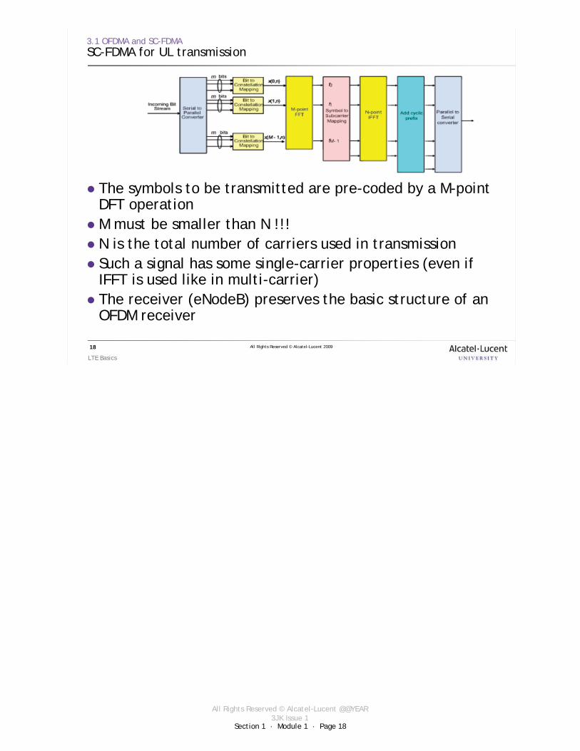
3.1 OFDMA and SC-FDMASC-FDMA for UL transmission
The symbols to be transmitted are pre-coded by a M-point DFT operationM must be smaller than N !!!N is the total number of carriers used in transmissionSuch a signal has some single-carrier properties (even if IFFT is used like in multi-carrier)The receiver (eNodeB) preserves the basic structure of an OFDM receiver

Section 1 · Module 1 · Page 19
All Rights Reserved © Alcatel-Lucent @@YEAR3JK Issue 1
All Rights Reserved © Alcatel-Lucent 2009
LTE Basics
19
3.1 OFDMA and SC-FDMAWhy “Single-carrier” FDMA?
The “original” symbols (x0, x1, x2 and x3) are retrieved in the vector obtained after IFFTThey will sequentially modulate a high-frequency carrier

Section 1 · Module 1 · Page 20
All Rights Reserved © Alcatel-Lucent @@YEAR3JK Issue 1
All Rights Reserved © Alcatel-Lucent 2009
LTE Basics
20
3.2 Multiple antennas techniques in LTE
Need for multiple antenna techniques
The highly-challenging requirements of LTE can only be met by using multiple antennas techniquesMultiple antennas can be used in both eNodeB and UE Multiantenna configuration determined by:
Multiantenna processing to be appliedNumber of Tx/Rx antennas
In LTE, the multiple antennas algorithm can be adapted on a “per-user-basis”
Section 1 · Module 1 · Page 21
All Rights Reserved © Alcatel-Lucent @@YEAR3JK Issue 1
All Rights Reserved © Alcatel-Lucent 2009
LTE Basics
21
3.2 Multiple antennas techniques in LTE
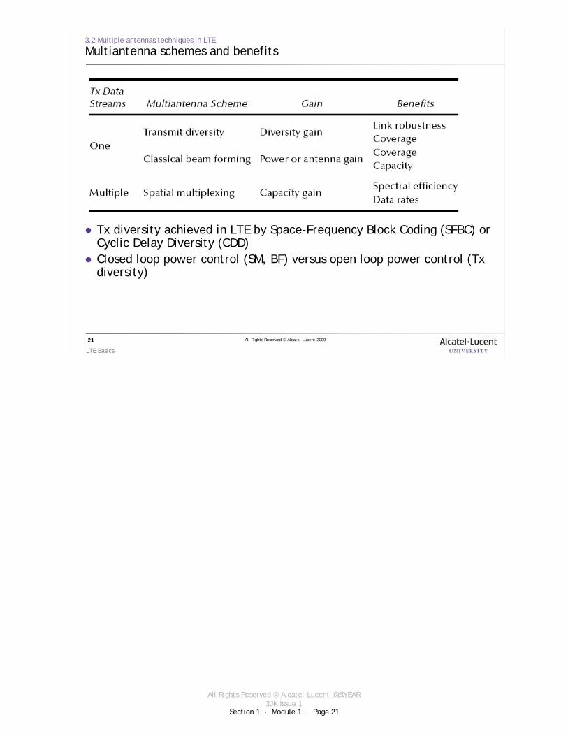
Multiantenna schemes and benefits
Tx diversity achieved in LTE by Space-Frequency Block Coding (SFBC) or Cyclic Delay Diversity (CDD)Closed loop power control (SM, BF) versus open loop power control (Txdiversity)

Section 1 · Module 1 · Page 22
All Rights Reserved © Alcatel-Lucent @@YEAR3JK Issue 1
All Rights Reserved © Alcatel-Lucent 2009
LTE Basics
22
3.2 Multiple antennas techniques in LTE
Cyclic delay diversity
Tx diversity relies on multiple antennas at the transmitter sideSpatial diversity can be achieved when transmitting one data streamCDD
The same signal, with different delays is transmitted by the different antennasA delay of the time-domain OFDM symbol can be perceived like a phase shift in the frequency domainTransparency to the UE, so it can be applied in conjunction with other techniques (SM)

Section 1 · Module 1 · Page 23
All Rights Reserved © Alcatel-Lucent @@YEAR3JK Issue 1
All Rights Reserved © Alcatel-Lucent 2009
LTE Basics
23
3.2 Multiple antennas techniques in LTE
Space-frequency block coding
SFBC is a variation of the famous STBC, better adapted to OFDMAlamouti’s scheme is applied to the frequency-domain OFDM symbol (prior to IFFT)This technique mainly enhances the robustness of the link
Section 1 · Module 1 · Page 24
All Rights Reserved © Alcatel-Lucent @@YEAR3JK Issue 1
All Rights Reserved © Alcatel-Lucent 2009
LTE Basics
24
3. PHY layer techniques
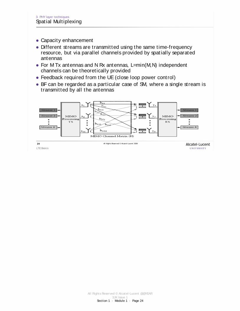
Spatial Multiplexing
Capacity enhancementDifferent streams are transmitted using the same time-frequency resource, but via parallel channels provided by spatially separated antennasFor M Tx antennas and N Rx antennas, L=min(M,N) independent channels can be theoretically provided Feedback required from the UE (close loop power control)BF can be regarded as a particular case of SM, where a single stream is transmitted by all the antennas

Section 1 · Module 1 · Page 25
All Rights Reserved © Alcatel-Lucent @@YEAR3JK Issue 1
All Rights Reserved © Alcatel-Lucent 2009
LTE Basics
25
4. OFDMA parameters for LTE
Section 1 · Module 1 · Page 26
All Rights Reserved © Alcatel-Lucent @@YEAR3JK Issue 1
All Rights Reserved © Alcatel-Lucent 2009
LTE Basics
26
4 OFDMA and LTE
OFDMA Parameters for LTE
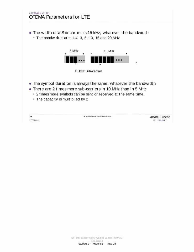
The width of a Sub-carrier is 15 kHz, whatever the bandwidthThe bandwidths are: 1.4, 3, 5, 10, 15 and 20 MHz
5 MHz 10 MHz
… …15 kHz Sub-carrier
The symbol duration is always the same, whatever the bandwidthThere are 2 times more sub-carriers in 10 MHz than in 5 MHz
2 times more symbols can be sent or received at the same time.The capacity is multiplied by 2

Section 1 · Module 1 · Page 27
All Rights Reserved © Alcatel-Lucent @@YEAR3JK Issue 1
All Rights Reserved © Alcatel-Lucent 2009
LTE Basics
27
4 OFDMA and LTE
OFDMA Parameters for LTE [cont.]
1200 (1201)900 (901)600 (601)300 (301)150 (151)75 (76)Number of useful sub-carriers
204815361024512256128Number of sub-carriers (FFT size)
30.72 MHz(8 × 3.84)
23.04 MHz(6 × 3.84)
15.36 MHz(4 × 3.84)
7.68 MHz(2 × 3.84)3.84 MHz1.92 MHz
(1/2 × 3.84)Sampling frequency
15 kHz Sub-carrier spacing
20 MHz15 MHz10 MHz5 MHz3 MHz1.4 MHzSpectrum allocation
5 MHz7.68 MHz
For the 5 MHz, there are 512 sub-carriers of 15 kHz, whereas the total band is 7.68 MHz. It is larger than the 5 MHz band!But only 301 sub-carriers are used (Pilot, DC, data), the other ones are guard sub-carriers:
301 Sub-ca * 15 kHz = 4.515 MHz
Used bandwidth
FFT sizes are chosen so that sampling rates are a multiple of the UMTS chip rate (3.84 MHz).
It eases the implementation of dual mode UMTS/LTE terminals

Section 1 · Module 1 · Page 28
All Rights Reserved © Alcatel-Lucent @@YEAR3JK Issue 1
All Rights Reserved © Alcatel-Lucent 2009
LTE Basics
28
4 OFDMA and LTE
OFDMA Parameter for LTE [cont.]
The symbol duration depends on the sub-carrier bandwidth.
2 Cyclic Prefixes are defined:Long CP: 16.67 micro secondsShort CP: 4.69 micro seconds
The total duration of a symbol is:
Useful duration + CP = 66.6 + 16.67 Total duration = 83.33 µs (long CP)
1 1 66.615
UsefulSymbolDuration sSub CarrierBW kHz
= = = μ−
#4#3#2#1
User 1
User 1
User 1
User 2
User 2
User 2
User 2
User 3
User 3
User 3User 4User 4
Time
Section 1 · Module 1 · Page 29
All Rights Reserved © Alcatel-Lucent @@YEAR3JK Issue 1
All Rights Reserved © Alcatel-Lucent 2009
LTE Basics
29
Exercise 1
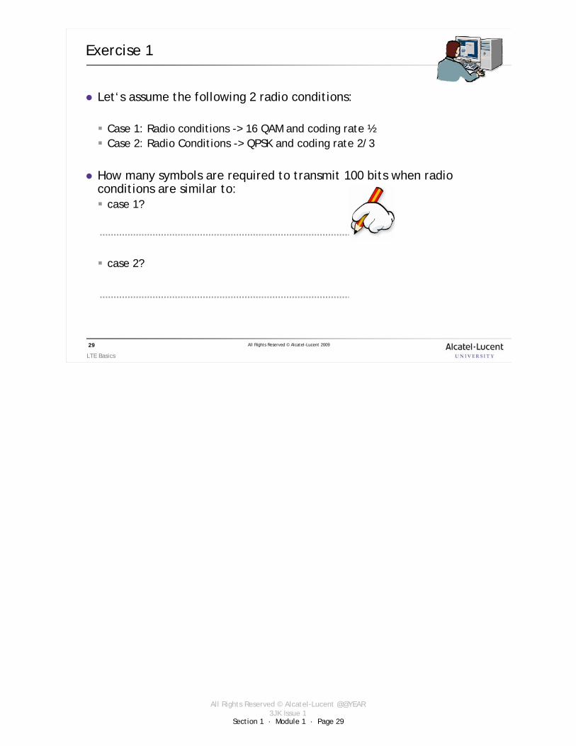
Let‘s assume the following 2 radio conditions:
Case 1: Radio conditions -> 16 QAM and coding rate ½Case 2: Radio Conditions -> QPSK and coding rate 2/3
How many symbols are required to transmit 100 bits when radioconditions are similar to:
case 1?
case 2?

Section 1 · Module 1 · Page 30
All Rights Reserved © Alcatel-Lucent @@YEAR3JK Issue 1
All Rights Reserved © Alcatel-Lucent 2009
LTE Basics
30
Exercise 2
Let‘s assume the following:Guard time for symbol = 2 µsTotal symbol duration = 8 * guard timeTotal Bandwidth = 5 MHzBest modulation = 64 QAM and coding rate: 2/3
Taking in account the above assumptions, could you determine the maxbit rate this system can reach?
Note: The values are not LTE compliant (this is only an exercise !)
Hint: determine the number of sub-carriers.

Section 1 · Module 1 · Page 31
All Rights Reserved © Alcatel-Lucent @@YEAR3JK Issue 1
All Rights Reserved © Alcatel-Lucent 2009
LTE Basics
31
5. Radio Frame Structure

Section 1 · Module 1 · Page 32
All Rights Reserved © Alcatel-Lucent @@YEAR3JK Issue 1
All Rights Reserved © Alcatel-Lucent 2009
LTE Basics
32
5. Radio Frame Structure
Basic Frame Structure
FDD is commonly referred to as “paired spectrum” transmissionThe FDD RF frame is called Type 1 by the 3GPP.The RF length is 10 ms.
RF #3RF #2RF #1 ……
DL Carrier
UL Carrier
The radio frame is made up of 10 sub-frames of 1 ms each.Each sub-frame is made up of 2 slots of 0.5ms each.
RF #1
10 sub-frames
2 slots
RF #3RF #2RF #1
#9#8#7#6#5#4#3#2#1#0
#2#1

Section 1 · Module 1 · Page 33
All Rights Reserved © Alcatel-Lucent @@YEAR3JK Issue 1
All Rights Reserved © Alcatel-Lucent 2009
LTE Basics
33
5.1 Resource units on the radio interface
Slots
Each slot is made up of:7 symbols in case of short CP6 symbols in case of long (also called extended) CP
#9#8#7#6#5#4#3#2#1#0
RF #1
10 sub-frames
Tu= 66.7µs
Tu = Useful Symbol DurationTcp = Cyclic Prefix durationTecp = Extended Cyclic Prefix duration
#7
Tcp = 4.7 µs
#6#5#4#3#2#1
#6#5#4#3#2#1
Tecp = 16.7 µs
#2#1

Section 1 · Module 1 · Page 34
All Rights Reserved © Alcatel-Lucent @@YEAR3JK Issue 1
All Rights Reserved © Alcatel-Lucent 2009
LTE Basics
34
5.1 Resource units on the radio interface
Resource Block
A slot can be represented as follows:
#7#6#5#4#3#2#1
time
Frequency
5 MHz (300 sub-ca)10 MHz (600 sub-ca)
1 sub-carrier/1 OFDM symbol is called a Resource Element
A group of 12 sub-carriers/7(or 6) symbols is
called a Resource Block (RB)
For data transmission, the minimum amount of resources allocable is 2 RBs.
#289
#149
#300

Section 1 · Module 1 · Page 35
All Rights Reserved © Alcatel-Lucent @@YEAR3JK Issue 1
All Rights Reserved © Alcatel-Lucent 2009
LTE Basics
35
5.1 Resource units on the radio interface
Resource block: a different view
There are 84 resource elements (subcarriers) composing a RB (72 for the long CP)The way that the subcarriers are allocated is: 7 OFDMA symbols x 12 subcarriers/OFDMA symbol = 84 subcarriersThe 7 OFDMA symbols which are part of a RB span 0.5ms (1 slot, ½ subframe)The physical bandwidth of a RB is 180 KHz

Section 1 · Module 1 · Page 36
All Rights Reserved © Alcatel-Lucent @@YEAR3JK Issue 1
All Rights Reserved © Alcatel-Lucent 2009
LTE Basics
36
5.1 Resource units on the radio interface
Resource Element Group
The Resource Block is not well suited for the control channel (the radio signaling).
The control channels are mapped to the Resource Elements Groups (REGs), which represent less radio resources
A REG is made up of 4 (or 6 if there are pilot sub-carriers) sub-carriers during 1 OFDM symbol.
Sub-carriers
Symbols
1 REG
#12
#11
#10
#9
#8
#7
#6
#5
#4
#3
#2
#1

Section 1 · Module 1 · Page 37
All Rights Reserved © Alcatel-Lucent @@YEAR3JK Issue 1
All Rights Reserved © Alcatel-Lucent 2009
LTE Basics
37
6. Protocol Stack

Section 1 · Module 1 · Page 38
All Rights Reserved © Alcatel-Lucent @@YEAR3JK Issue 1
All Rights Reserved © Alcatel-Lucent 2009
LTE Basics
38
6 Protocol Stack
Radio Interface Overview
An End-to-end service is mapped on the radio interface on a radio bearer.The radio bearer is managed by the radio protocols running in the eNodeB and the UE.
Radio S1
S1 and S5/S8 bearers refer to specific LTE interface within eUTRAN and EPC
EPS: Extended Packet Service (the “assembly” of the radio interface eUTRAN and the evolved Packet Core )

Section 1 · Module 1 · Page 39
All Rights Reserved © Alcatel-Lucent @@YEAR3JK Issue 1
All Rights Reserved © Alcatel-Lucent 2009
LTE Basics
39
6.1 Protocols architecture
Protocols on the radio interface
eNode-B
PDCP
Physical Layer
MAC Layer
RLC
RRC
NAS
Control PlaneUser Plane
PDCP
Physical Layer
MAC Layer
RLC
RRC
NAS
Control PlaneUser Plane
Transport Channel
Logical Channel
Radio Bearer
Physical Channel
Non-Access StratumSignaling between Core Network and UE
Radio Signaling
RRC = Radio Resource Control
PDCP = Packet Data Convergence Protocol
RLC = Radio Link Control
PDCP, RLC and MAC can be seen as layer-2 sublayers
L2 L2
Section 1 · Module 1 · Page 40
All Rights Reserved © Alcatel-Lucent @@YEAR3JK Issue 1
All Rights Reserved © Alcatel-Lucent 2009
LTE Basics
40
Higher layers
6.2 Protocols on the radio interface
RRC
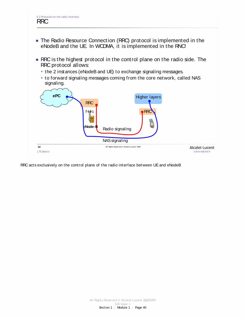
The Radio Resource Connection (RRC) protocol is implemented in the eNodeB and the UE. In WCDMA, it is implemented in the RNC!
RRC is the highest protocol in the control plane on the radio side. The RRC protocol allows:
the 2 instances (eNodeB and UE) to exchange signaling messages.to forward signaling messages coming from the core network, called NAS signaling.
RRC
RRC
eNode-B
ePC
Radio signaling
NAS signaling
RRC acts exclusively on the control plane of the radio interface between UE and eNodeB
Section 1 · Module 1 · Page 41
All Rights Reserved © Alcatel-Lucent @@YEAR3JK Issue 1
All Rights Reserved © Alcatel-Lucent 2009
LTE Basics
41
6.2 Protocols on the radio interface
2.3 RRC [cont.]
RRC protocol is in charge of:Broadcast of System Information related to the Non-Access Stratum (NAS) and Access Stratum (AS)PagingEstablishment, maintenance and release of an RRC connection between the UE and E-UTRAN including:
Allocation of temporary identifiers between UE and E-UTRAN.Configuration of signaling radio bearer(s) for RRC connection.Low priority SRB and high priority SRB.Security functions including key management.Establishment, configuration, maintenance and release of point to point Radio Bearers.
Mobility functions including:UE measurement reporting and control of the reporting for inter-cell and inter-RAT mobility.Handover.UE cell selection and reselection and control of cell selection and reselection.Context transfer at handover.
Establishment, configuration, maintenance and release of Radio Bearers for MBMS services.QoS management functions.UE measurement reporting and control of the reporting.NAS direct message transfer to/from NAS from/to UE.
The NAS layer performs:
Authentication
Security control
Idle mode mobility handling
Idle mode paging origination
MBMS = Multimedia Broadcast/Multicast Service
SRB = Signaling Radio Bearer

Section 1 · Module 1 · Page 42
All Rights Reserved © Alcatel-Lucent @@YEAR3JK Issue 1
All Rights Reserved © Alcatel-Lucent 2009
LTE Basics
42
6.2 Protocols on the radio interface
2.3 RRC [cont.]
RRC uses the following states:
RRC_IdleThe UE is not connected. There is no radio link. The network knows that the UE is present on the network and is able to reach it in case of incoming call.The UE switches in idle mode when it is connected and there is no traffic. This allows to save radio resources and its battery.
RRC_ConnectedThe UE has an e-UTRAN-RRC connection.The network can transmit/receive data to/from the UE and knows its location at the cell level.The network manages the mobility with handover.

Section 1 · Module 1 · Page 43
All Rights Reserved © Alcatel-Lucent @@YEAR3JK Issue 1
All Rights Reserved © Alcatel-Lucent 2009
LTE Basics
43
6.2 Protocols on the radio interface
PDCP
The main services provided by the Packet Data Convergence Protocol (PDCP) are:
PDCP
Physical Layer
MAC Layer
RLC
RRC
NAS
User Plane Control PlaneFor the user plane:
IP header compression and decompression with the Robust Header Compression (ROHC) method onlyCipheringTransfer of user dataIn-sequence delivery of upper layer PDUs at HO in the uplink
For the control plane:Ciphering and Integrity Protection to secure the transmission of core network signaling

Section 1 · Module 1 · Page 44
All Rights Reserved © Alcatel-Lucent @@YEAR3JK Issue 1
All Rights Reserved © Alcatel-Lucent 2009
LTE Basics
44
6.2 Protocols on the radio interface
RLC
The Radio Link Control (RLC) protocol provides the following services:
PDCP
Physical Layer
MAC Layer
RLC
RRC
NAS
User Plane Control PlaneSegmentation of SDU according to the sizeRe-Segmentation of PDURadio Bearer to logical channel mapping
Transfer of data in 3 modes:
TM Transparent ModeWithout retransmission. For real-time service.
UM Unacknowledged ModeWithout retransmission, but error statistics (BLER)It can be used for the signaling.
AM Acknowledged ModeWith retransmission. For non real-time services, like web browsing.

Section 1 · Module 1 · Page 45
All Rights Reserved © Alcatel-Lucent @@YEAR3JK Issue 1
All Rights Reserved © Alcatel-Lucent 2009
LTE Basics
45
6.3 MAC Layer
Media Access Control functions
The MAC layer provides the following services:
PDCP
Physical Layer
MAC Layer
RLC
RRC
NAS
User Plane Control PlaneLogical Channel to Transport channel mapping
Scheduling:There is no dedicated channel allocated to a UE. Time and frequency resources are dynamically shared between the users in DL and UL.The scheduler is part of the MAC layer and controls the assignment of uplink and downlink resources.

Section 1 · Module 1 · Page 46
All Rights Reserved © Alcatel-Lucent @@YEAR3JK Issue 1
All Rights Reserved © Alcatel-Lucent 2009
LTE Basics
46
6.3 MAC Layer
MAC Scheduler
eNodeB
DL
UL
Frequency
Time
The scheduler (in the eNodeB) determines dynamically, each 1 ms (each subframe), which UEs is scheduled to transmit/receive data on the UL/DL shared channel, and what resources to be used
The basic time-frequency unit is the resource block (RB).
To select the adapted modulation and coding rate, the scheduler needs measurement reports in DL and UL.

Section 1 · Module 1 · Page 47
All Rights Reserved © Alcatel-Lucent @@YEAR3JK Issue 1
All Rights Reserved © Alcatel-Lucent 2009
LTE Basics
47
2.3 MAC Layer
MAC scheduler [cont.]
eNode-B
eNodeB
Scheduler
Buffer
Data
Multiplexing
Modulation, Coding
Transmission
eNodeB
UE
DL channel quality measurement
In downlink, the scheduler needs the following inputs to schedule data:
Amount of dataData typeRadio resource availableRadio Condition in DL
The UE reports regularly its measurement report, called Channel Quality Indicator (CQI).

Section 1 · Module 1 · Page 48
All Rights Reserved © Alcatel-Lucent @@YEAR3JK Issue 1
All Rights Reserved © Alcatel-Lucent 2009
LTE Basics
48
UE
2.3 MAC Layer
MAC scheduler [cont.]
eNode-B
eNodeB
Scheduler
Buffer
Data
Multiplexing
Modulation, Coding
Transmission
eNodeB
UL channel quality measurement
In uplink, the mechanism is similar but:
Measurements are made by the eNodeB
The eNodeB scheduler controls the UE transmission
Request to transmit

Section 1 · Module 1 · Page 49
All Rights Reserved © Alcatel-Lucent @@YEAR3JK Issue 1
All Rights Reserved © Alcatel-Lucent 2009
LTE Basics
49
7. ALU Solution for LTE

Section 1 · Module 1 · Page 50
All Rights Reserved © Alcatel-Lucent @@YEAR3JK Issue 1
All Rights Reserved © Alcatel-Lucent 2009
LTE Basics
50
7. ALU Solution for LTE
Architecture overview
EPS = eUTRAN + ePC
Long Term Evolution (LTE) is the newest 3GPP standard for mobilenetwork technology.
P-GWS-GW
HSS
PDN
MGW
IMS
Transport
PCRF
PSTN
User and control
Control only
LTE
OFDM
SC-FDMA
eUTRAN
ePC
All-IP network carries all types of traffic, including VoIP.
Provides control functions for LTE access networks.
Routes and forwards user data packets to eNodeB.
Connects UE to external packet data networks.
AAA
Controls QoS policy for each service data flow that passes through the SGW and PGW.
IMS network provides services, including VoIP.
S1-MME
S1-U S5/S8
Gx
SGi
SWx
SGi
S6aS11
S6b
MMEx2
Gxc

Section 1 · Module 1 · Page 51
All Rights Reserved © Alcatel-Lucent @@YEAR3JK Issue 1
All Rights Reserved © Alcatel-Lucent 2009
LTE Basics
51
7. ALU Solution for LTE
eUTRAN
eUTRAN comes from evolved UTRANThe interface between the user equipment (UE) and eNodeBeNodeB is the key element of UTRAN, implementing the air interface according to 3-GPP release 8 specificationsThe key points of the air interface are:
OFDMA for DL, SC-FDMA for ULSmart antenna algorithms (Tx Diversity, Spatial Multiplexing, BeamForming)Turbo-codes for error correctionAdaptive modulation and codingBoth FDD and TDD are described by the standard
The resources allocation and scheduling on the air it is entirely done by the eNodeBThe other physical device communicating over the eUTRAN is the User Equipment
Section 1 · Module 1 · Page 52
All Rights Reserved © Alcatel-Lucent @@YEAR3JK Issue 1
All Rights Reserved © Alcatel-Lucent 2009
LTE Basics
52
7. ALU Solution for LTE
ePC
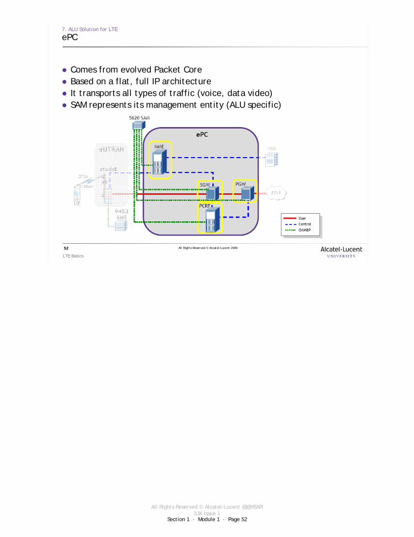
Comes from evolved Packet CoreBased on a flat, full IP architectureIt transports all types of traffic (voice, data video)SAM represents its management entity (ALU specific)

Section 1 · Module 1 · Page 53
All Rights Reserved © Alcatel-Lucent @@YEAR3JK Issue 1
All Rights Reserved © Alcatel-Lucent 2009
LTE Basics
53
7. ALU Solution for LTE
ePC components
MME (Mobility Management entity)Control plane onlyResponsible for mobility and air link managementAuthentication, tracking, paging, bearer activation
Serving Gateway (SGW)Forwarding of user plane data packetsAnchor point for inter eNodeB and inter-technology handover (HO between LTE and earlier 3GPP technologies)
Packet data Gateway (PGW)Connection point between UE and external data networks Anchor point for inter-technology mobility (non 3GPP technologies)Traffic policy enforcement, charging support
Policy and Charging Rules Function (PCRF)Dynamic control of the QoS for the provided servicesGives to SGW and PGW the rules for the treatment of each service data flow

Section 1 · Module 1 · Page 54
All Rights Reserved © Alcatel-Lucent @@YEAR3JK Issue 1
All Rights Reserved © Alcatel-Lucent 2009
LTE Basics
54
External references (other than ALU docs)
G. Gomez, D. Morales Jimenez and oth., “Long term evolution: 3 GPP LTE radio and cellular access technology”, Taylor and Francis Group, 2009.E. Dahlman, S. Parkvall and oth., “3G Evolution: HSPA and LTE for mobile broadband”, Elsevier Academic Press, 2007.Ericsson’s white paper: “LTE: an introduction”, 2009.Motorola’s white paper: “Long term evolution (LTE): overview of LTE Air-Interface”, 2007.D. Astely, E. Dahlman and oth., “LTE: the evolution of mobile broadband”, IEEE Communications Magazine, April 2009, pp. 44-51.H.G. Myung, “Single Carrier FDMA”, 2008, available online at:http://hgmyung.googlepages.com/scfdma.