Embed Size (px)
Citation preview

LTE-Advanced Physical Layer Design and Test Challenges: Carrier Aggregation
Presented by
Agilent Technologies
Agenda
• Overview of carrier aggregation- Carrier aggregation modes- Operating bands- Cell configuration- Deployment scenarios- Layer 1 and 2 structure- Resource scheduling
• Design and test challenges• Summary/Agilent solutions• Resources
March, 2014
LTE-Advanced Carrier Aggregation
2

LTE Major Features
Feature CapabilityAccess modes FDD & TDDChannel BW (1RB = 12 subcarriers = 180 kHz)
1.4 MHz 3 MHz 5 MHz 10 MHz 15 MHz 20 MHz6 RB 15 RB 25 RB 50 RB 75 RB 100 RB
Transmission Scheme Downlink: OFDMA (Orthogonal Frequency Division Multiple Access)
Uplink: SC-FDMA (Single Carrier Frequency Division Multiple Access
Modulation Schemes QPSK, 16QAM, 64QAMMIMO Technology Downlink: Tx diversity, Rx diversity, Single-User MIMO (up to 4x4),
beamformingUplink: Multi-User MIMO
Peak Data Rates Downlink: 150 Mbps (2x2 MIMO, 20 MHz, 64QAM); 300 Mbps (4x4 MIMO, 20 MHz, 64QAM) Uplink: 75 Mbps @ 20 MHz BW, 64QAM
Bearer services Packet only – no circuit switched voice or data services are supported voice must use VoIP
Transmission Time Interval
1 ms
March, 2014
LTE-Advanced Carrier Aggregation
3

Release 10 and Beyond ProposalsRadio Aspects
1. Carrier aggregation
2. Enhanced uplink multiple accessa) Clustered SC-FDMAb) Simultaneous Control and Data
3. Enhanced multiple antenna transmissiona) Downlink 8 antennas, 8 streamsb) Uplink 4 antennas, 4 streams
4. Relaying
5. Home eNB mobility enhancements
6. Heterogeneous network support
7. Self Optimizing networks (SON)
8. Coordinated Multipoint (CoMP)
Rel 10 LTE-A proposed to ITU
Other Release 10 and beyond
March, 2014
LTE-Advanced Carrier Aggregation
4

What is Carrier Aggregation?
• Extends the maximum transmission bandwidth, up to 100 MHz, by aggregating up to five LTE carriers – also known as component carriers (CCs)
• Lack of sufficient contiguous spectrum forces use of carrier aggregation to meet peak data rate targets:- 1 Gbps in the downlink and 500 Mbps in the uplink
• Motivation:- Achieve wide bandwidth transmissions - Facilitate efficient use of fragmented spectrum- Efficient interference management for control channels in heterogeneous networks
fBand A ≈ Band B
March, 2014
LTE-Advanced Carrier Aggregation
5
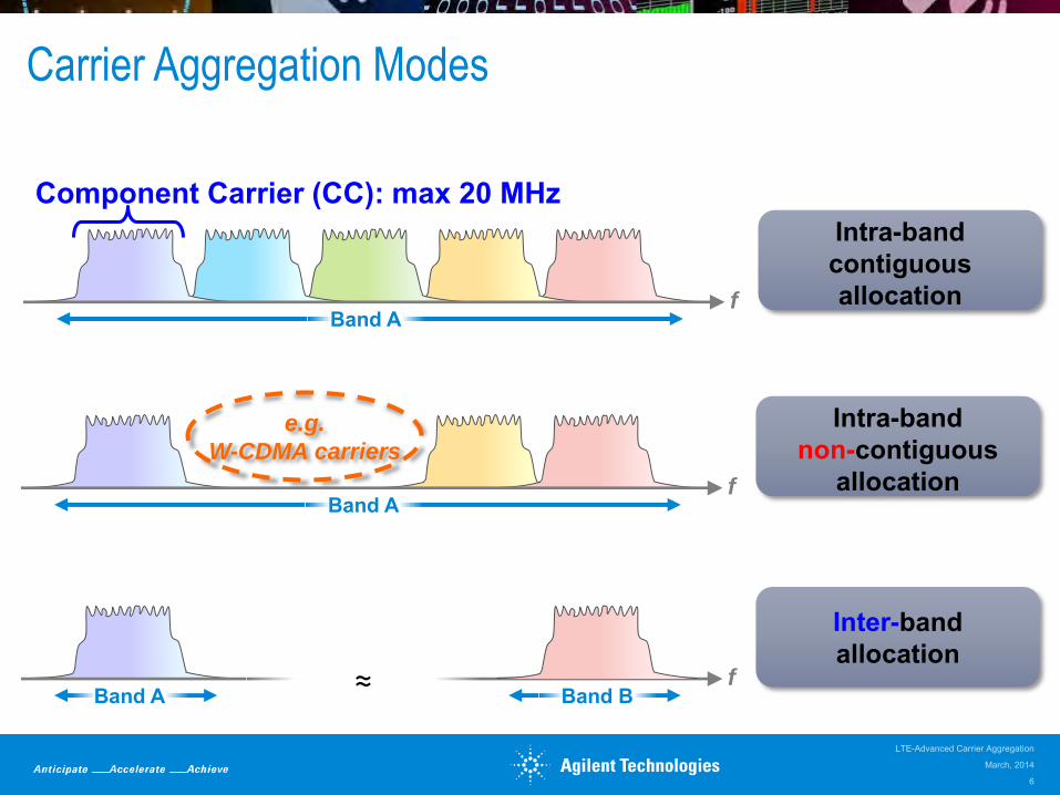
Inter-band allocation
fBand A ≈ Band B
Band A
Component Carrier (CC): max 20 MHz
f
Intra-band contiguous allocation
Intra-band non-contiguous
allocationfBand A
e.g.
W-CDMA carriers
Carrier Aggregation Modes
March, 2014
LTE-Advanced Carrier Aggregation
6

Release 10:o Signaling to support up to 5 CCo Scenarios limited to 2 CCso Maximum aggregated bandwidth is 40MHzo TDD inter-band with same DL-UL configurationso Prioritized support intra band contiguous and inter bando Rest of scenarios were postponed to later Releases
Intra - band Contiguous CA
E-UTRA CA
Band
E-UTRA operating
Band
Uplink (UL) band Downlink (DL) band Duplex mode
UE transmit / BS receive Channel BW MHz
UE receive / BS transmit Channel BW MHz FUL_low (MHz) – FUL_high
(MHz) FDL_low (MHz) – FDL_high
(MHz) CA_40 40 2300 – 2400 [401)] 2300 – 2400 [401)] TDD CA_1 1 1920 – 1980 40 2110 – 2170 40 FDD
[1) For the first phase of LTE TDD CA for UE side, with eventual goal for 50MHz]
Inter - band Non -Contiguous CA
E-UTRA CA Band
E-UTRA operating
Band
Uplink (UL) band Downlink (DL) band Duplex mode
UE transmit / BS receive Channel BW MHz
UE receive / BS transmit Channel BW MHz FUL_low (MHz) – FUL_high
(MHz) FDL_low (MHz) – FDL_high
(MHz)
CA_1-5 1 1920 – 1980 101) 2110 – 2170 10 FDD 5 824 – 849 101) 869 – 894 10
1) Only one uplink component carrier is used in any of the two frequency bands at any time.
Modes and Deployments
Inter-band Intra-band cont
1 23
CA
Band C
ombinations
Rel.10
March, 2014
LTE-Advanced Carrier Aggregation
7
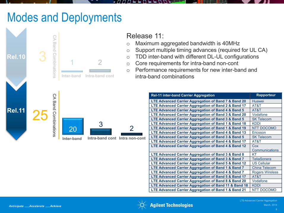
Release 11:o Maximum aggregated bandwidth is 40MHzo Support multiple timing advances (required for UL CA)o TDD inter-band with different DL-UL configurationso Core requirements for intra-band non-conto Performance requirements for new inter-band and
intra-band combinationsInter-band Intra-band cont
Inter-band
1 23
CA
Band C
ombinations
25
CA
Band C
ombinations
Rel.10
Intra-band cont
Modes and Deployments
Intra non-cont
Rel.11
2203
March, 2014
LTE-Advanced Carrier Aggregation
8
Rel-11 inter-band Carrier Aggregation RapporteurLTE Advanced Carrier Aggregation of Band 7 & Band 20 HuaweiLTE Advanced Carrier Aggregation of Band 2 & Band 17 AT&TLTE Advanced Carrier Aggregation of Band 4 & Band 5 AT&TLTE Advanced Carrier Aggregation of Band 3 & Band 20 VodafoneLTE Advanced Carrier Aggregation of Band 3 & Band 5 SK TelecomLTE Advanced Carrier Aggregation of Band 1 & Band 18 KDDILTE Advanced Carrier Aggregation of Band 1 & Band 19 NTT DOCOMOLTE Advanced Carrier Aggregation of Band 4 & Band 13 EricssonLTE Advanced Carrier Aggregation of Band 3 & Band 5 SK TelecomLTE Advanced Carrier Aggregation of Band 4 & Band 17 AT&TLTE Advanced Carrier Aggregation of Band 4 & Band 12 Cox
CommunicationsLTE Advanced Carrier Aggregation of Band 3 & Band 8 KTLTE Advanced Carrier Aggregation of Band 3 & Band 7 TeliaSoneraLTE Advanced Carrier Aggregation of Band 5 & Band 12 US CellularLTE Advanced Carrier Aggregation of Band 1 & Band 7 China TelecomLTE Advanced Carrier Aggregation of Band 4 & Band 7 Rogers WirelessLTE Advanced Carrier Aggregation of Band 5 & Band 17 AT&TLTE Advanced Carrier Aggregation of Band 8 & Band 20 VodafoneLTE Advanced Carrier Aggregation of Band 11 & Band 18 KDDILTE Advanced Carrier Aggregation of Band 1 & Band 21 NTT DOCOMO

2
Release 12:o Core requirements uplink CA in inter-bando Performance requirements for intra-band non-contiguouso Core analysis for 3 component carriers in inter-bando Maximum aggregated bandwidth is 50MHz
Inter-band Intra-band cont
20Inter-band
1 23
CA
Band C
ombinations
25
CA
Band C
ombinations
48 12Inter-band
25Inter 3 CC
95
CA
Band C
ombinations
Intra-band cont
10Intra non-cont
Rel.10
Rel.11
Intra-band cont
Modes and Deployments
Intra non-cont
3
Rel.12
March, 2014
LTE-Advanced Carrier Aggregation
9
Rel.13
13 new configs so far
CA
Band C
ombinations

New UE Categories
UE Category
Data Rate DL/UL
(Mbps)
Downlink UplinkMax number
of layersMax number
of layersSupport for
64QAM
1 10 / 5 1 1 No
2 50 / 25 2 1 No
3 100 / 50 2 1 No
4 150 / 50 2 1 No
5 300 / 75 4 1 Yes
6 300 / 50 2 or 4 1 or 2 No
7 300 / 100 2 or 4 1 or 2 No
8 3000 / 1500 8 4 Yes
LTELTE
-A
March, 2014
LTE-Advanced Carrier Aggregation
10
Carrier Aggregation- Cell Configuration
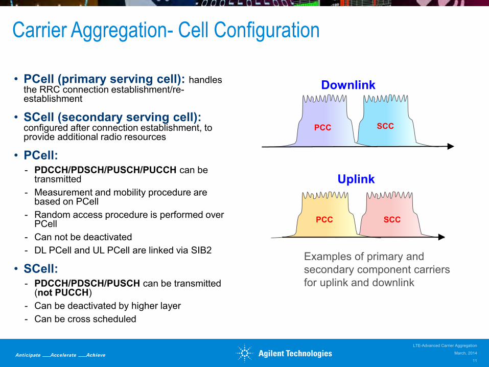
• PCell (primary serving cell): handles the RRC connection establishment/re-establishment
• SCell (secondary serving cell): configured after connection establishment, to provide additional radio resources
• PCell:- PDCCH/PDSCH/PUSCH/PUCCH can be
transmitted- Measurement and mobility procedure are
based on PCell- Random access procedure is performed over
PCell- Can not be deactivated- DL PCell and UL PCell are linked via SIB2
• SCell:- PDCCH/PDSCH/PUSCH can be transmitted
(not PUCCH)- Can be deactivated by higher layer- Can be cross scheduled
March, 2014
LTE-Advanced Carrier Aggregation
11
Uplink
Examples of primary and secondary component carriers for uplink and downlink
PCC SCC
Downlink
PCC SCC

TDD Carrier Aggregation with Different Subframe Configuration – 3GPP Release 11
• Release 10 only allowed same UL/DL configuration in all component carriers
• Release 11 different UL/DL configuration can be used - the UE is required to transmit and receive in parallel in some subframes
• TDD UEs would need duplex filter similar to FDD UEs to be able to transmit and receive simultaneously
• If UE doesn’t have duplex filter, it would follow the UL/DL configuration of PCC and conflicting subframes in SCC are not used by the UE
March, 2014
LTE-Advanced Carrier Aggregation
12
#0 #2 #3 #4 #5 #7 #8 #9#1 #6DL S UL DL DL DL S UL DL DL
DL S UL UL DL DL S UL UL DL
PCCUL/DL Config #1
SCCUL/DL Config #2
Subframes 3 and 8 of SCC can only be used by full-duplex UEs
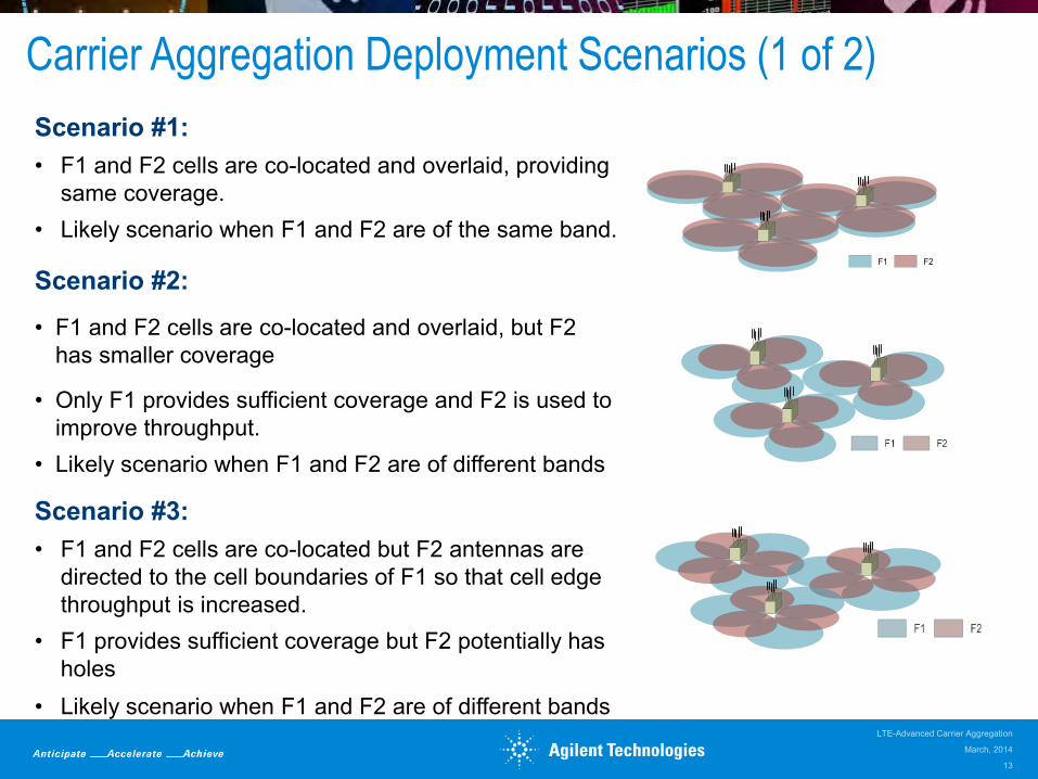
Carrier Aggregation Deployment Scenarios (1 of 2)
F1 F2
Scenario #1:• F1 and F2 cells are co-located and overlaid, providing
same coverage. • Likely scenario when F1 and F2 are of the same band.
March, 2014
LTE-Advanced Carrier Aggregation
13
Scenario #2:
• F1 and F2 cells are co-located and overlaid, but F2 has smaller coverage
• Only F1 provides sufficient coverage and F2 is used to improve throughput.
• Likely scenario when F1 and F2 are of different bands
Scenario #3:• F1 and F2 cells are co-located but F2 antennas are
directed to the cell boundaries of F1 so that cell edge throughput is increased.
• F1 provides sufficient coverage but F2 potentially has holes
• Likely scenario when F1 and F2 are of different bands

Carrier Aggregation Deployment Scenarios (2 of 2)
Scenario #4:• F1 provides macro coverage and on F2 Remote
Radio Heads (RRHs) are used to improve throughput at hot spots.
• Likely scenario when F1 and F2 are of different bands,
Scenario #5:• Similar to scenario #2, but frequency selective
repeaters are deployed to extend coverage for one of the frequencies.
March, 2014
LTE-Advanced Carrier Aggregation
14

Layer 2 Structure for Carrier Aggregation
• Data aggregation happens in MAC layer, changes to protocol layer is kept to a minimum except some new RRC messages to add, remove or reconfigure SCC
• The MAC layer divides the data between different CCs and separate HARQ processes for each CC
Independent HARQ per
CC
Segm.ARQ etc
Multiplexing UE1
Segm.ARQ etc...
Scheduling / Priority Handling
Logical Channels
Transport Channels
MAC
RLC Segm.ARQ etc
Segm.ARQ etc
PDCPROHC ROHC ROHC ROHC
Radio Bearers
Security Security Security Security
...
HARQ HARQ...
Multiplexing UEn
HARQ HARQ...
CC1 CCx... CC1 CCy...
Multiplexing
...
Scheduling / Priority Handling
Transport Channels
MAC
RLC
PDCP
Segm.ARQ etc
Segm.ARQ etc
Logical Channels
ROHC ROHC
Radio Bearers
Security Security
HARQ HARQ...
CC1 CCx...Layer 2 Structure for the UL
(3GPP TR 36.912 V10.0.0, Figure 5.2.1-2)Layer 2 Structure for the DL
(Derived from 3GPP TR 36.912 V10.0.0, Figure 5.2.1--1)
RRC
IP RRC IP RRC
March, 2014
LTE-Advanced Carrier Aggregation
15

MAC to Physical Layer Mapping for Carrier Aggregation
• There is one transport block, up to two in case of spatial multiplexing, and one HARQ entity per scheduled component carrier
• A UE can be scheduled over multiple component carriers simultaneously
March, 2014
LTE-Advanced Carrier Aggregation
16
….
Example of 5 component carriers each with different modulation format
Channel coding
HARQ
modulation
Resource mapping
CC2
Channel coding
HARQ
modulation
Resource mapping
CC1
One UE
TrBlk 1 TrBlk 2
Channel coding
HARQ
modulation
Resource mapping
CC5
TrBlk 5
..
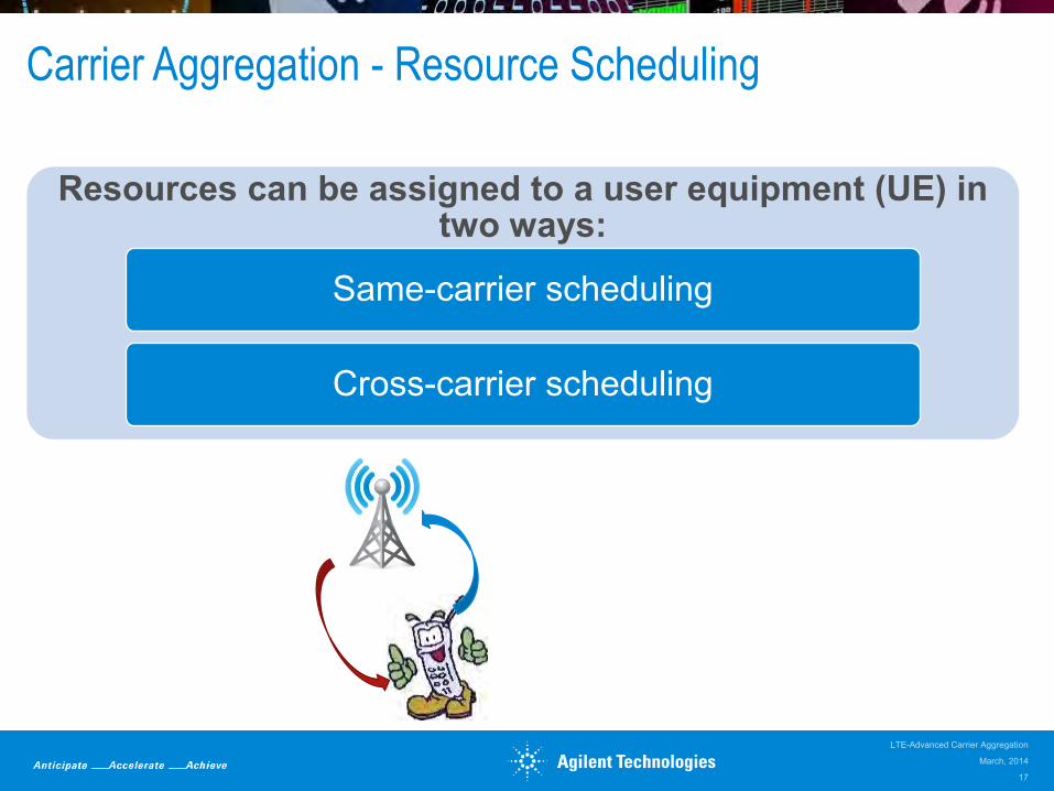
Carrier Aggregation - Resource Scheduling
Resources can be assigned to a user equipment (UE) in two ways:
Same-carrier scheduling
Cross-carrier scheduling
March, 2014
LTE-Advanced Carrier Aggregation
17

Same Carrier Scheduling
• Separate PDCCH for each CC
• Resource scheduling are on the same component carrier(Downlink assignments/ Uplink grants)
• Reusing Release 8/9 PDCCH structure and DCI (Downlink Control Information) formats for backward compatibility
• Each component carrier can be analyzed individually
PDSCHSubframe
PDCCHCC#0 CC#1 CC#2
PDCCH PDCCH
PDSCH PDSCH
PDCCH (Physical Downlink Control Channel) carries the uplink and downlink resource grant.
f
March, 2014
LTE-Advanced Carrier Aggregation
18
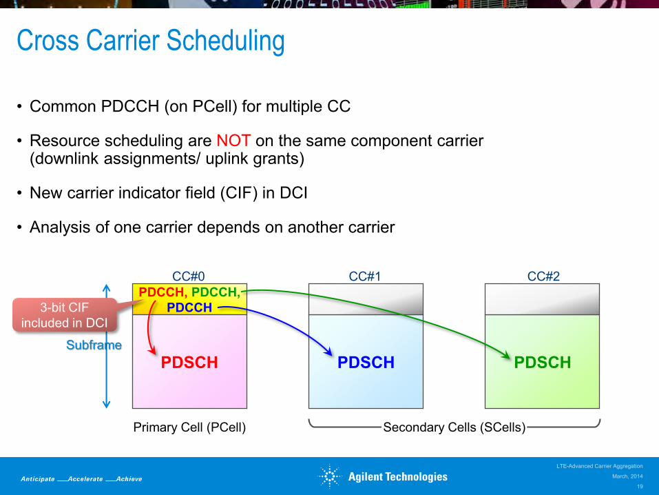
Cross Carrier Scheduling
• Common PDCCH (on PCell) for multiple CC
• Resource scheduling are NOT on the same component carrier(downlink assignments/ uplink grants)
• New carrier indicator field (CIF) in DCI
• Analysis of one carrier depends on another carrier
PDCCH, PDCCH,PDCCH
PDSCH PDSCH PDSCHSubframe
CC#0 CC#1 CC#2
Primary Cell (PCell) Secondary Cells (SCells)
3-bit CIF included in DCI
March, 2014
LTE-Advanced Carrier Aggregation
19

Macro Cell
Pico CellCC1 for Macro Cell
CC2 for Macro Cell
CC2 Low Power
CC1Low Power
Cross-Carrier Scheduling:Interference management for control channels in heterogeneous networks
• Cross-carrier scheduling provides interference management for control channels known as Inter-Cell Interference Coordination (ICIC) for PDCCH.
• In this example, CC1 of Macro Cell would cause high interference to CC1 of pico cell, therefore pico cell uses CC2 for PDCCH messages to schedule PDSCH transmission on CC1
• Macro cell uses CC1 to schedule PDSCH transmission on both CC1 and CC2
PDC
CH
PDSCH
PDSCH scheduled by PDCCH from
CC1
Macro Cell
PDC
CH
PDSCH
PDSCH scheduled by PDCCH from
CC2
Pico Cell
CC1
CC2
CC1
CC2
Cross-carrier scheduling avoids control channel interference
March, 2014
LTE-Advanced Carrier Aggregation
20
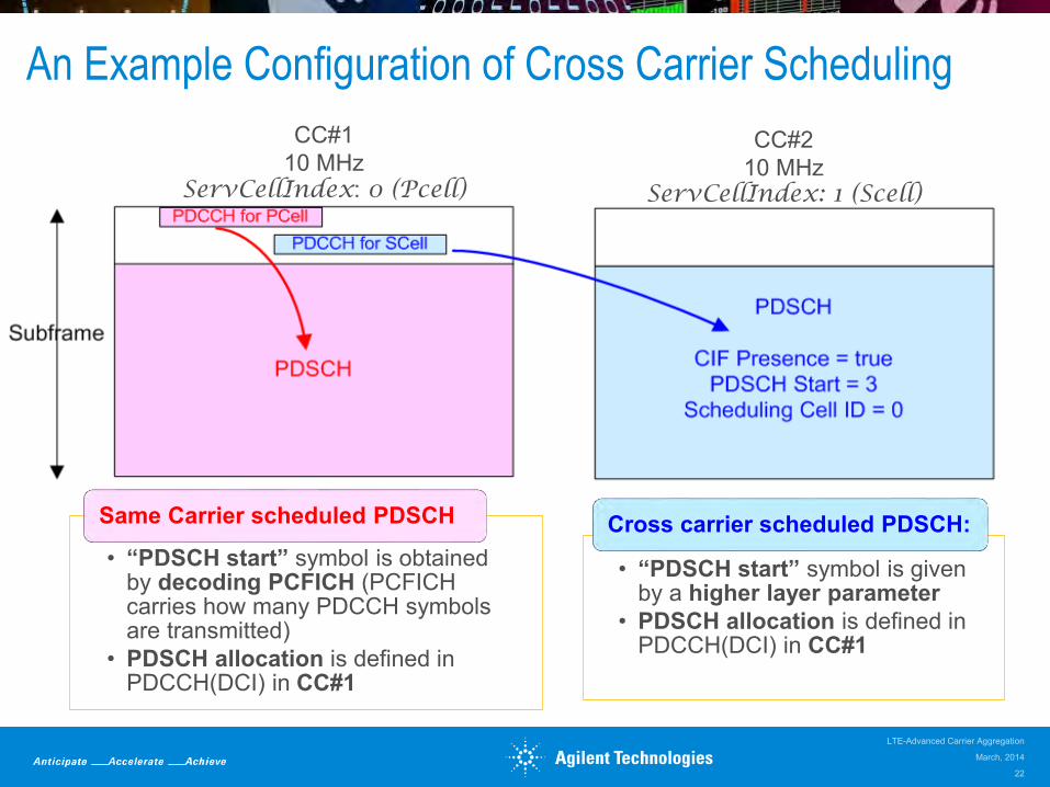
An Example Configuration of Cross Carrier Scheduling
CC#110 MHz
ServCellIndex: 0 (Pcell)
CC#210 MHz
ServCellIndex: 1 (Scell)
• “PDSCH start” symbol is obtained by decoding PCFICH (PCFICH carries how many PDCCH symbols are transmitted)
• PDSCH allocation is defined in PDCCH(DCI) in CC#1
Same Carrier scheduled PDSCH
• “PDSCH start” symbol is given by a higher layer parameter
• PDSCH allocation is defined in PDCCH(DCI) in CC#1
Cross carrier scheduled PDSCH:
March, 2014
LTE-Advanced Carrier Aggregation
22
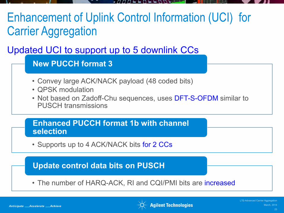
Enhancement of Uplink Control Information (UCI) for Carrier Aggregation
Updated UCI to support up to 5 downlink CCs
• Convey large ACK/NACK payload (48 coded bits)• QPSK modulation• Not based on Zadoff-Chu sequences, uses DFT-S-OFDM similar to
PUSCH transmissions
New PUCCH format 3
• Supports up to 4 ACK/NACK bits for 2 CCs
Enhanced PUCCH format 1b with channel selection
• The number of HARQ-ACK, RI and CQI/PMI bits are increased
Update control data bits on PUSCH
March, 2014
LTE-Advanced Carrier Aggregation
23
Agenda
• Overview of carrier aggregation- Carrier aggregation modes- Operating bands- Cell configuration- Deployment scenarios- Layer 1 and 2 structure- Resource scheduling
• Design and test challenges• Agilent solutions• Resources
March, 2014
LTE-Advanced Carrier Aggregation
24
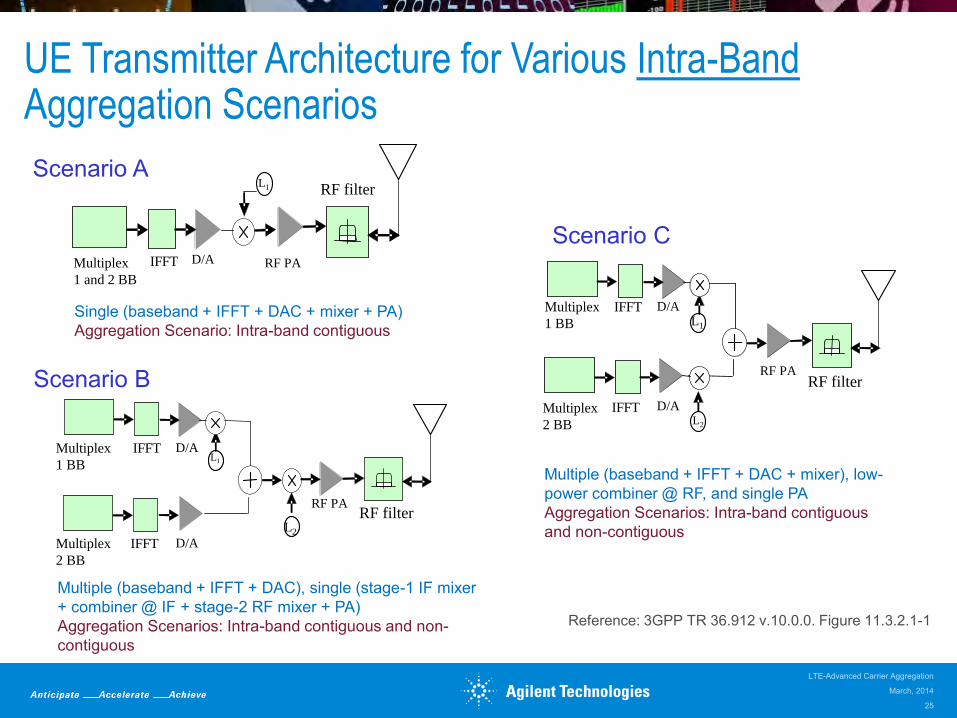
UE Transmitter Architecture for Various Intra-BandAggregation Scenarios
RF PA
RF filter
Multiplex
1 and 2 BB
D/AIFFT
L1
Single (baseband + IFFT + DAC + mixer + PA)Aggregation Scenario: Intra-band contiguous
Multiplex
1 BB
Multiplex
2 BB
IFFT
IFFT
D/A
D/A
L1
RF PA
L2
RF filter
Multiple (baseband + IFFT + DAC), single (stage-1 IF mixer + combiner @ IF + stage-2 RF mixer + PA)Aggregation Scenarios: Intra-band contiguous and non-contiguous
Multiplex
1 BB
Multiplex
2 BB
IFFT
IFFT
D/A
D/A
RF PARF filter
L2
L1
Multiple (baseband + IFFT + DAC + mixer), low-power combiner @ RF, and single PAAggregation Scenarios: Intra-band contiguous and non-contiguous
Scenario A
Scenario B
Scenario C
Reference: 3GPP TR 36.912 v.10.0.0. Figure 11.3.2.1-1
March, 2014
LTE-Advanced Carrier Aggregation
25
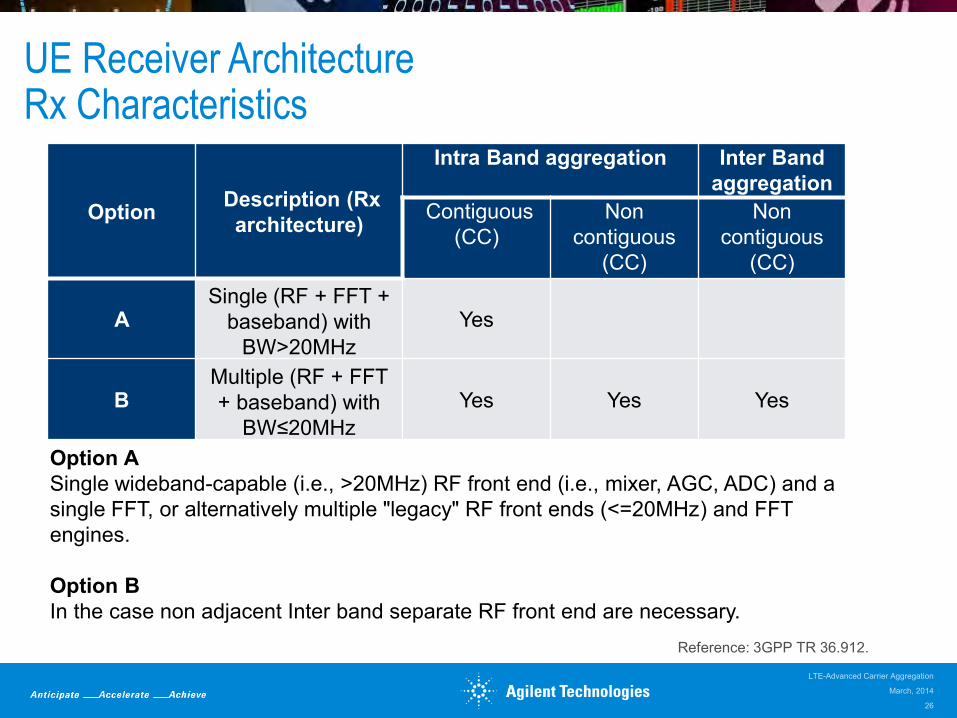
UE Receiver ArchitectureRx Characteristics
Option Description (Rx architecture)
Intra Band aggregation Inter Band aggregation
Contiguous (CC)
Non contiguous
(CC)
Non contiguous
(CC)
ASingle (RF + FFT +
baseband) with BW>20MHz
Yes
BMultiple (RF + FFT + baseband) with
BW≤20MHzYes Yes Yes
Option ASingle wideband-capable (i.e., >20MHz) RF front end (i.e., mixer, AGC, ADC) and a single FFT, or alternatively multiple "legacy" RF front ends (<=20MHz) and FFT engines.
Option BIn the case non adjacent Inter band separate RF front end are necessary.
Reference: 3GPP TR 36.912.
March, 2014
LTE-Advanced Carrier Aggregation
26
Design Challenges – Intra-Band CA
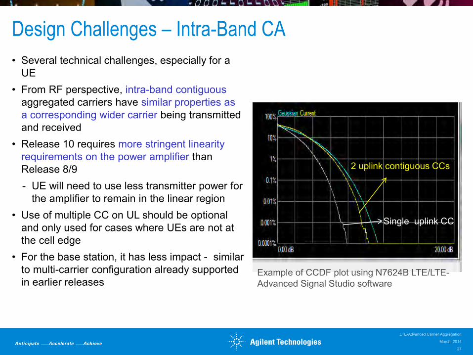
• Several technical challenges, especially for a UE
• From RF perspective, intra-band contiguous aggregated carriers have similar properties as a corresponding wider carrier being transmitted and received
• Release 10 requires more stringent linearity requirements on the power amplifier than Release 8/9- UE will need to use less transmitter power for
the amplifier to remain in the linear region• Use of multiple CC on UL should be optional
and only used for cases where UEs are not at the cell edge
• For the base station, it has less impact - similar to multi-carrier configuration already supported in earlier releases
Example of CCDF plot using N7624B LTE/LTE-Advanced Signal Studio software
2 uplink contiguous CCs
Single uplink CC
March, 2014
LTE-Advanced Carrier Aggregation
27

Design Challenges - Inter-band CA
Major challenges for the UE
• Multiple simultaneous receive chains
• Multiple simultaneous transmit chains
Challenging radio environment
• In terms of intermodulation and cross-modulation within the UE device.
• Need to design front-end components that help reduce harmonics, and other intermodulation products, which meet 3GPP requirements.
• Simultaneous transmit or receive with MIMO support add significantly to the challenge of antenna design
Less impact for the base station
• Similar to current base stations supporting multi-bands
Reference: 3GPP TR 36.912 v.10.0.0. Figure 11.3.2.1-1
Multiplex 1
BB
Multiplex 2
BB
IFFT
IFFT
D/A
D/ARF PA RF filterL2
L1RF PA
RF filter
RF filter
March, 2014
LTE-Advanced Carrier Aggregation
28

SystemVue LTE-Advanced Carrier Aggregation
Scenario number
Deployment scenarioTransmission BWs of LTE-A carriers
# of LTE-A component carriersDuplex modes
1Single-band contiguous spec. alloc. @ 3.5GHz band for FDD
UL: 40 MHz
DL: 80 MHz
UL: Contiguous 2x20 MHz CCsDL: Contiguous 4x20 MHz CCs
FDD
2Single-band contiguous spec. alloc. @ Band 40 for TDD
100 MHz Contiguous 5x20 MHz CCs TDD
4
Single-band, non-contiguous spec. alloc. @ 3.5GHz band for FDD
UL: 40 MHz
DL: 80 MHz
UL: Non-contiguous 1x20 + 1x20 MHz CCsDL: Non-contiguous 2x20 + 2x20 MHz CCs
FDD
Re
Im
Env
1 1 0 1 0
1 1 0 1 0
UE1_Dat a
HARQ _Bit s
f r m _TD
f r m _FD
UE1_M odSym bols
UE1_ChannelBit s
SC_St at usUE1_PM I
LTE_A
DL
Src
UEs_n_SCID=0;0;0;0;0;0 [[0, 0, 0, 0, 0, 0]]UserDefinedAntMappingMatrix=NO
LTE_A_DL_Src_2
FcChange
Spect rum Anal yzer
CCDF
Stop=10msStart=0s
CCDF_CA
CCDF
Stop=10msStart=0sWoCA
ModOUT
QUADOUT
FreqPhas eQ
IAm p
Re
Im1 1 0 1 0
1 1 0 1 0
UE1_Dat a
HARQ _Bit s
f r m _TD
f r m _FD
UE1_M odSym bols
UE1_ChannelBit s
SC_St at usUE1_PM I
LTE_A
DL
Src
UEs_n_SCID=0;0;0;0;0;0 [[0, 0, 0, 0, 0, 0]]UserDefinedAntMappingMatrix=NO
LTE_A_DL_Src_4
ModOUT
QUADOUT
FreqPhas eQ
IAm p
Re
Im1 1 0 1 0
1 1 0 1 0
UE1_Dat a
HARQ _Bit s
f r m _TD
f r m _FD
UE1_M odSym bols
UE1_ChannelBit s
SC_St at usUE1_PM I
LTE_A
DL
Src
UEs_n_SCID=0;0;0;0;0;0 [[0, 0, 0, 0, 0, 0]]UserDefinedAntMappingMatrix=NO
LTE_A_DL_Src_3
ModOUT
QUADOUT
FreqPhas eQ
IAm p
Re
Im
ModOUT
QUADOUT
FreqPhas eQ
IAm p
1 1 0 1 0
1 1 0 1 0
UE1_Dat a
HARQ _Bit s
f r m _TD
f r m _FD
UE1_M odSym bols
UE1_ChannelBit s
SC_St at usUE1_PM I
LTE_A
DL
Src
UEs_n_SCID=0;0;0;0;0;0 [[0, 0, 0, 0, 0, 0]]UserDefinedAntMappingMatrix=NO
LTE_A_DL_Src_1
20MHzCCs
March, 2014
LTE-Advanced Carrier Aggregation
29

Test Challenges: Power Amplifier Characterization
Agilent Solution:• Signal Studio software generates LTE-
Advanced signals compliant to 3GPP standard to test power and modulation characteristics of components and transmitters.
• Supports up to 5 component carriers within up to 160 MHz I/Q bandwidth with MXG vector signal generator
• CCDF curve to get insight into the waveform power statistics as system parameters are varied
Test Challenge: Characterizing the LTE-Advanced UE or eNB power amplifier presents RF challenge. The different carrier aggregation configurations will stress the amplifier in different ways since each will have different peak-to-average ratios.
Configure up to 5 component
carriers
March, 2014
LTE-Advanced Carrier Aggregation
30

Test Challenges: Analyze eNB Unwanted Emissions inside Sub-Block Gap
Agilent Solutions:• X-Series LTE-Advanced measurement
application (N9080B/N9082B)• Supports LTE-Advanced RF conformance testing
per 3GPP Release 10/11 for both UE and eNB• Supports the new cumulative ACLR (CACLR)
and cumulative SEM requirement inside sub-block gap
Test Challenge: For Release 11, there is new RF conformance testing required for base station transmitters to measure unwanted emissions inside sub-block gap contributed from carriers on both sides of the gap
Depending on sub-block gap, one or both inner
offsets can overlap resulting in CACLR
March, 2014
LTE-Advanced Carrier Aggregation
31
Sub-block 1
Base Station RF Bandwidth
Sub-block 2
fBand A
Ex. W-CDMA carriers
Sub-block gap
Refer to “LTE-Advanced Base Station RF Conformance Testing” paper for full detail on RF conformance testing
≈
Resource
block
Test Challenges: Inter-Band Carrier Aggregation Analysis
Band A Band B
N7109A
OR
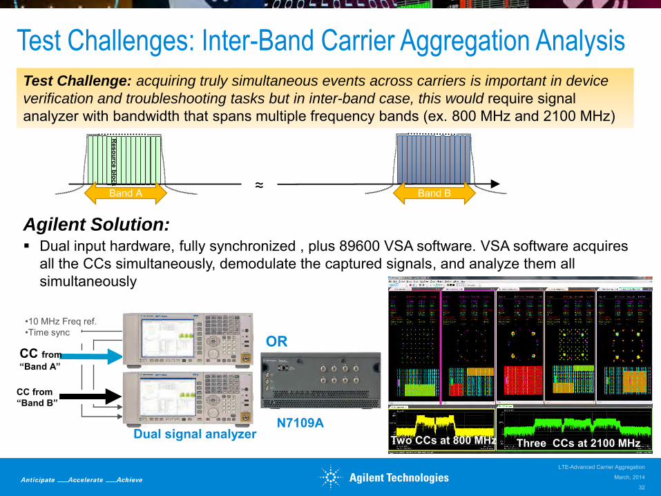
Test Challenge: acquiring truly simultaneous events across carriers is important in device
verification and troubleshooting tasks but in inter-band case, this would require signal analyzer with bandwidth that spans multiple frequency bands (ex. 800 MHz and 2100 MHz)
•10 MHz Freq ref.•Time sync
CC from “Band A”
CC from “Band B”
Dual signal analyzer
Agilent Solution: Dual input hardware, fully synchronized , plus 89600 VSA software. VSA software acquires
all the CCs simultaneously, demodulate the captured signals, and analyze them all simultaneously
Two CCs at 800 MHz Three CCs at 2100 MHz
March, 2014
LTE-Advanced Carrier Aggregation
32
Test Challenges: Analyze Time Alignment Error between Multiple Component Carriers
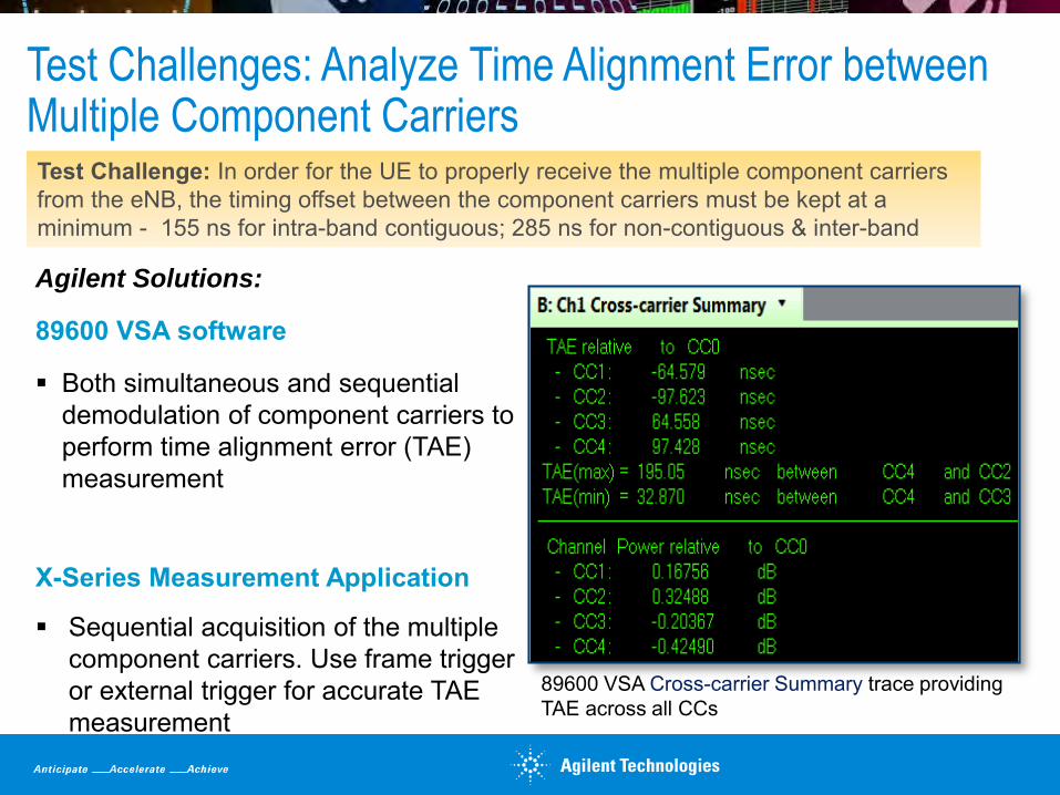
Agilent Solutions:
89600 VSA software
Both simultaneous and sequential demodulation of component carriers to perform time alignment error (TAE) measurement
X-Series Measurement Application
Sequential acquisition of the multiple component carriers. Use frame trigger or external trigger for accurate TAE measurement
Test Challenge: In order for the UE to properly receive the multiple component carriers from the eNB, the timing offset between the component carriers must be kept at a minimum - 155 ns for intra-band contiguous; 285 ns for non-contiguous & inter-band
89600 VSA Cross-carrier Summary trace providing TAE across all CCs

Test Challenges: Simultaneous Analysis of Inter-Band Aggregation plus Downlink MIMO
Agilent Solution:
• N7109A multi-channel signal analysis system: 2, 4 or 8 channels, 40 MHz demodulation BW per channel
Test Challenge: when inter-band carrier aggregation is combined with spatial multiplexing MIMO, it requires test tools that has a minimum of 4 inputs (two inputs per CC).
Up to 8 channels
MIMO Info trace for CC0
MIMO Info trace for CC1
Frequency response for CC0
Frequency response for CC0
Constellation for CC0
Constellation for CC1
Example of 2x2 MIMO and inter-band carrier aggregation with two component carriers
March, 2014
LTE-Advanced Carrier Aggregation
34

Test Challenges: LTE-Advanced eNB Receiver Test
Agilent Solution
• Create either FDD or TDD signals
• PUCCH format 3 and 1b enable generation of feedback for multiple component carriers
• PUSCH UCI multiplexing enhanced for feedback of up to 5 component carriers
• Predefined configuration of LTE-Advanced conformance tests with randomized HARQ-ACK in PUCCH
Test Challenge: Test eNB ability to decode UCI transmissions with feedback for multiple component carriers.
March, 2014
LTE-Advanced Carrier Aggregation
35
Agenda
• Overview of carrier aggregation- Carrier aggregation modes- Operating bands- Cell configuration- Deployment scenarios- Layer 1 and 2 structure- Resource scheduling
• Design and test challenges• Summary/Agilent solutions• Resources
March, 2014
LTE-Advanced Carrier Aggregation
37

Summary
• Carrier aggregation is one of the most important features for LTE-Advanced enabling:- Higher data rates- Facilitate efficient use of fragmented spectrum- Interference management in heterogeneous networks
• It is introduced in LTE Release 10 with enhancements in Release 11 and more improvements planned in Rel. 12 and beyond
• It introduces various design challenges, especially for UE • New test challenges for both UE and eNB • Agilent was first to market with LTE-Advanced solution addressing system
simulation, signal generation and analysis tools
March, 2014
LTE-Advanced Carrier Aggregation
38

Agilent LTE and LTE-Advanced Portfolio
Signal Generators
RDX for DigRF v4
Systems for RF and Protocol Conformance
RF Module Development
RF Proto RF Chip/module
DesignSimulation
BTS and MobileBB Chipset Development
L1/PHY
FPGA and ASIC
Conformance
RF and BB Design
IntegrationL1/PHY System
Design Validation
System LevelRF Testing
BTSor
MobileProtocol Development
L2/L3
DigRF v4
Pre-Conformance
Network Deployment
Manufacturing
SystemVue (BB) ADS/GG (RF/A)
N5971A IFT Software
Scopes and Logic Analyzers
Baseband Generator and
Channel Emulator
Signal creationsoftware
RF Handheld Analyzers
EXM Manufacturing test set
Battery draincharacterization
E7515A UXM wireless test set
RF & Protocol test platforms
Signal Analyzers with LTE/LTE-Advanced Measurement Apps
89600 WLA 89600 VSA
N7109A Multi-Channel Signal Analysis
System
March, 2014
LTE-Advanced Carrier Aggregation
39

LTE/LTE-Advanced Signal Studio SoftwareFor RF Transmitter & Receiver Tests
Physical layer-coded signals for Transmitter amplifier test (Basic option)
Transport layer-coded signals for Receiver BLER test (Advanced option)
User-friendly, parameterized, and reconfigurable setupReal-time uplink LTE FDD / TDD signal creationCreate multi-carrier signals in one waveformCreate MIMO precoding with embedded multi-path fadingSupports multiple signal-generator platforms:
X-Series MXG/EXG
1st generation MXG
ESG-C / PSG
PXB
EXT
M9381A VSG
SystemVueEDA software
EXM
March, 2014
LTE-Advanced Carrier Aggregation
40
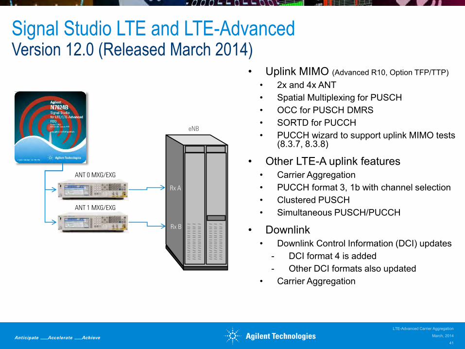
Signal Studio LTE and LTE-AdvancedVersion 12.0 (Released March 2014)
• Uplink MIMO (Advanced R10, Option TFP/TTP)
• 2x and 4x ANT• Spatial Multiplexing for PUSCH• OCC for PUSCH DMRS• SORTD for PUCCH• PUCCH wizard to support uplink MIMO tests
(8.3.7, 8.3.8)
• Other LTE-A uplink features• Carrier Aggregation• PUCCH format 3, 1b with channel selection• Clustered PUSCH• Simultaneous PUSCH/PUCCH
• Downlink • Downlink Control Information (DCI) updates
- DCI format 4 is added- Other DCI formats also updated
• Carrier Aggregation
ANT 0 MXG/EXG
ANT 1 MXG/EXG
Rx A
Rx B
eNB
March, 2014
LTE-Advanced Carrier Aggregation
41

N7649B Test Case ManagerNow Supports Receiver Performance Tests
• Simple and easy to use user interface- Provides minimum set of parameters and
configure instruments according to the standard requirements
• TS36.141 Receiver Test for FDD and TDD- Clause 7 Receiver Characteristics (Rel-10)- Clause 8 Receiver Performance (Rel-9)- eNB Type selection
• Wide Area, Local Area, Home BS• Supported Platforms
- Clause 7: MXG-B, EXG-B, MXG-A, ESG-C, PXB
- Clause 8: MXG-B(*), EXG-B(*), PXB• * Requires external fader
• Graphic to show how carriers are positioned• SCPI log to assist remote automation• 30 days free trial license is available
Visit www.agilent.com/find/TCM to find out more!
March, 2014
LTE-Advanced Carrier Aggregation
42

LTE/LTE-Advanced Signal Analysis ApplicationsFor RF Transmitter Test
Scalable transmitter test solutions
Tailor capability & performance fromSISO to MIMO/beamforming
Use 89600 VSA with varieties of demodulation result traces/capabilities for deep-dive analysis in R&D, design validation, troubleshooting, etc.
Use X-Series measurement applications with ease-of-use presets, demodulation and power/ spectrum measurements for manual & automated tests in QA, conformance testing, manufacturing, etc.
Co-reside with multi-formats in one box
W-CDMA/HSPA+, GSM/EDGE, cdma2000, 1xEV-DO, WLAN…
89600B VSA Softwareultimate analysis flexibility for R&D
X-Series Signal Analyzer(EXA/MXA/PXA)
N9080B/82B Software One-button measurementsfor conformance testing
March, 2014
LTE-Advanced Carrier Aggregation
43

• Carrier Aggregation: Simultaneous demodulation of up to 5 CCs.
• DL (OFDMA) & UL (SC-FDMA) in a single option
• All LTE/LTE-A modulation types: BPSK, QPSK, 16QAM, 64QAM, CAZAC (Zadoff-Chu)
• FDD/TDD 4x4 DL MIMO analysis & TDD 8x2 DL Beamforming analysis
• 8x8 DL MIMO analysis for LTE-Advanced FDD & TDD
• UL MIMO single channel analysis for LTE-Advanced
• 89600 WLA: MAC, RRC, RLC layer add-on to the 89600 VSA for UL & DL LTE FDD
• Rich varieties of modulation analysis results & traces with full PHY channel-based color coding
• Supports multiple platforms: Systemvue EDA simulation SW, X-Series signal analyzers, Oscilloscopes, logic analyzers, PXI VSAs, N7109A multi-channel signal analyzer
44
LTE/LTE-Advanced RF Transmitter Test Solution89600 VSA Software
89600 VSA
89600 WLA
March, 2014
LTE-Advanced Carrier Aggregation

LTE/LTE-Advanced RF Transmitter Test SolutionN9080B/N9082B X-Series Measurement Application
Output power level tests- Channel power- Transmit ON/OFF power (TDD base station
only)
Transmitted signal quality - EVM, frequency error, I/Q offset…- Time alignment error - Comprehensive list of EVM measurements and
color-coded displays to troubleshoot errors
Unwanted emissions - Spectrum emissions mask (SEM) - Adjacent channel leakage ratio (ACLR) - Cumulative ACLR (CACLR) and cumulative
SEM for non-contiguous CA- Occupied bandwidth - Spurious emissions- Transmitter intermodulation
All measurements support LTE and LTE-A with up to 5 component carriers, both contiguous and non-contiguous carrier aggregation (CA)
March, 2014
LTE-Advanced Carrier Aggregation
45
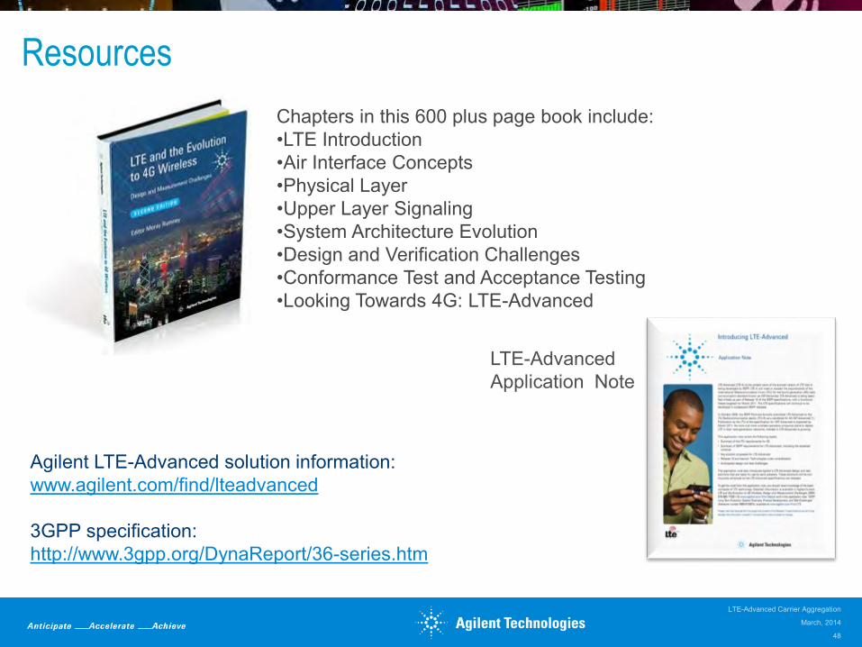
Resources
Agilent LTE-Advanced solution information: www.agilent.com/find/lteadvanced
3GPP specification:http://www.3gpp.org/DynaReport/36-series.htm
LTE-Advanced Application Note
Chapters in this 600 plus page book include:•LTE Introduction•Air Interface Concepts•Physical Layer•Upper Layer Signaling•System Architecture Evolution•Design and Verification Challenges•Conformance Test and Acceptance Testing•Looking Towards 4G: LTE-Advanced
March, 2014
LTE-Advanced Carrier Aggregation
48

March, 2014
LTE-Advanced Carrier Aggregation
49