Embed Size (px)
Citation preview

LTE-A Base Station Transmitter Tests According to TS 36.141 Rel. 10 Application Note
Products:
ı R&S®FSW
ı R&S®FSQ
ı R&S®FSV
ı R&S®SMW200A
ı R&S®SMU200A
ı R&S®SMBV100A
ı R&S®SMJ100A
3GPP TS36.141 defines conformance tests for E-
UTRA base stations (eNodeB). Release 10 (LTE-
Advanced) added several tests, such as those
for multicarrier scenarios.
This application note describes how all required
transmitter (Tx) tests (TS36.141 Chapter 6) can
be performed quickly and easily by using signal
and spectrum analyzers from Rohde & Schwarz.
A few tests additionally require signal
generators from Rohde & Schwarz.
Examples illustrate the manual operation. A free
software program enables and demonstrates
remote operation.
The LTE base station receiver (Rx) tests (TS36.141
Chapter 7) are described in Application Note
1MA195.
The LTE base station performance (Px) tests
(TS36.141 Chapter 8) are described in Application
Note 1MA162.
Ber
nhar
d S
chul
z
5.20
15 -
1M
A15
4_4e
App
licat
ion
Not
e

Table of Contents
1MA154_4e Rohde & Schwarz 2
Table of Contents
1 Introduction ......................................................................................... 4
2 General Transmitter Test Information ............................................... 6
2.1 Note ............................................................................................................................... 6
2.2 Multicarrier Test Scenarios ......................................................................................... 6
2.3 Tx Test Setup ............................................................................................................... 9
2.4 Instruments and Options ..........................................................................................10
2.5 Multistandard Radios and TS 37.141 .......................................................................13
3 Transmitter Tests (Chapter 6) .......................................................... 14
3.1 Basic Operation .........................................................................................................15
3.1.1 FSx Spectrum and Signal Analyzer .............................................................................15
3.1.2 SMx Vector Signal Generator ......................................................................................18
3.1.3 R&S TSrun Demo Program .........................................................................................21
3.2 Base Station Output Power (Clause 6.2) .................................................................27
3.2.1 Home BS Output Power Measurements (Clause 6.2.6…6.2.8) ..................................29
3.3 Output Power Dynamics (Clause 6.3) ......................................................................51
3.3.1 Total Power Dynamic Range (Clause 6.3.2) ...............................................................51
3.4 Transmit ON/OFF Power (Clause 6.4) ......................................................................53
3.5 Transmitted Signal Quality (Clause 6.5) ..................................................................57
3.5.1 Frequency Error (Clause 6.5.1) and Error Vector Magnitude (Clause 6.5.2) ..............57
3.5.2 Time Alignment Error (Clause 6.5.3) ...........................................................................59
3.5.3 DL RS Power (Clause 6.5.4) .......................................................................................64
3.6 Unwanted Emissions (Clause 6.6) ...........................................................................65
3.6.1 Occupied Bandwidth (Clause 6.6.1) ............................................................................66
3.6.2 Adjacent Channel Leakage Power (ACLR) (Clause 6.6.2) .........................................68
3.6.3 Operating Band Unwanted Emissions (SEM) (Clause 6.6.3) ......................................76
3.6.4 Transmitter Spurious Emissions (Clause 6.6.4) ..........................................................78
3.7 Transmitter Intermodulation (Clause 6.7) ...............................................................82
4 Appendix ........................................................................................... 91
4.1 R&S TSrun Program ..................................................................................................91
4.2 References ..................................................................................................................96
4.3 Additional Information ..............................................................................................97
4.4 Ordering Information .................................................................................................97

Table of Contents
1MA154_4e Rohde & Schwarz 3
The following abbreviations are used in this Application Note for Rohde & Schwarz test
equipment:
ı The R&S®SMW200A vector signal generator is referred to as the SMW.
ı The R&S®SMATE200A vector signal generator is referred to as the SMATE.
ı The R&S®SMU200A vector signal generator is referred to as the SMU.
ı The R&S®SMBV100A vector signal generator is referred to as the SMBV.
ı The R&S®FSQ signal analyzer is referred to as the FSQ.
ı The R&S®FSV spectrum analyzer is referred to as the FSV.
ı The R&S®FSW spectrum analyzer is referred to as the FSW.
ı The SMW, SMATE, SMBV and SMU are referred to as the SMx.
ı The FSQ, FSV and FSW are referred to as the FSx.
ı The software R&S®TSrun is referred to as the TSrun.
ı The software E-UTRA/LTE and LTE- Advanced Signal Analysis is referred to as
the PC-SW.

Introduction
Note
1MA154_4e Rohde & Schwarz 4
1 Introduction
Long Term Evolution (LTE) networks or Evolved Universal Terrestrial Radio Access (E-
UTRA) (from Releases 8 and 9) have long since been introduced into daily usage. As a
next step, 3GPP has added several extensions in Release 10, known as LTE-
Advanced (LTE-A). These include a multicarrier aggregation option, changes to MIMO
(up to 8x8 in the downlink and introduction of MIMO in the uplink).
An overview of the technology behind LTE and LTE-Advanced is provided in
Application Note 1MA111.
The LTE-A conformance tests for base stations (eNodeB) are defined in 3GPP TS
36.141 Release 10 [1] and include transmitter (Tx), receiver (Rx) and performance (Px)
tests. T&M instruments from Rohde & Schwarz can be used to perform all tests easily
and conveniently.
This application note describes the transmitter (Tx) tests in line with TS36.141 Chapter
6. It explains the necessary steps in manual operation for signal and spectrum
analyzers and signal generators. A free remote-operation software program is
additionally provided. With this software, users can remotely control and demo tests on
base stations quickly and easily. It also provides the SCPI commands required to
implement each test in user-defined test programs.
The receiver (Rx) tests (TS36.141 Chapter 7) are described in Application Note
1MA195 and the performance (Px) tests (TS36.141 Chapter 8) are covered in
Application Note 1MA162.
The following abbreviations are used in this application note:
Abbreviations for 3GPP standards
TS 36.141 Application Note
E-UTRA FDD or TDD LTE (FDD or TDD)
UTRA-FDD W-CDMA
UTRA-TDD TD-SCDMA
GSM, GSM/EDGE GSM
Table 1-1: Abbreviations for 3GPP standards
Table 1-2 gives an overview of the Transmitter tests defined in line with Chapter 6 of
TS36.141. All can be carried out using instruments from Rohde & Schwarz. These
tests are individually described in this application note.
Introduction
Note
1MA154_4e Rohde & Schwarz 5
Covered TX tests
Chapter
(TS36.141)
Test
Base station output power
6.2 Base station output power
6.2.6 Home BS output power for adjacent channel WCDMA protection
6.2.7 Home BS output power for adjacent channel LTE protection
6.2.8 Home BS output power for co-channel LTE protection
Output power dynamics
6.3.2 Total dynamic range
Transmit ON/OFF power
6.4 Transmit ON/OFF power
Transmitter signal quality
6.5.1 Frequency error
6.5.2 Error vector magnitude
6.5.3 Time alignment error
6.5.4 DL RS power
Unwanted emissions
6.6.1 Occupied bandwidth
6.6.2 Adjacent channel leakage power ratio
6.6.3 Operating band unwanted emissions
6.6.4 Transmitter spurious emissions
Transmitter intermodulation
6.7 Transmitter intermodulation
Table 1-2: Covered TX tests

General Transmitter Test Information
Note
1MA154_4e Rohde & Schwarz 6
2 General Transmitter Test Information
2.1 Note
Very high power occurs on base stations! Be sure to use suitable attenuators in order
to prevent damage to the test equipment.
2.2 Multicarrier Test Scenarios
Multicarrier configurations are a significant portion of LTE-A according to Rel. 10.
These allow multiple carriers (even those using a different radio access technology) to
be transmitted simultaneously, but independently of one another, from a single base
station (multicarrier, MC). Another special attribute of LTE-A is the ability to link
multiple carriers using carrier aggregation (CA). This allows an increase in the data
rate to an individual subscriber (user equipment, UE). Overlapping of adjacent carriers
is also possible, making more effective use of the bandwidth.
A distinction is made between the following CA scenarios:
ı Intra-band contiguous
ı Inter-band non-contiguous
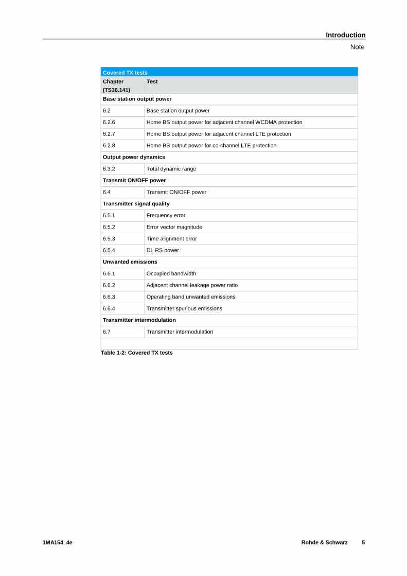
Intra-band contiguous carrier aggregation
In this scenario, multiple carriers are transmitted in parallel within a single bandwidth of
an LTE operating band (bands 1 to 25 for FDD and 33 to 43 for TDD; see [1]). Fig. 2-1
defines carrier aggregation. Table 2-1 lists the CA bands defined in [1]. This scenario is
currently possible in bands 1 and 40.
General Transmitter Test Information
Multicarrier Test Scenarios
1MA154_4e Rohde & Schwarz 7
Fig. 2-1: Definition of intra-band contiguous carrier aggregation [1].
Intra-band contiguous CA operating bands
LTE
CA Band
LTE
Band
Uplink (UL) operating band
FUL_low – FUL_high
[MHz]
Downlink (DL) operating band
FDL_low – FDL_high
[MHz]
Duplex Mode
CA_1 1 1920 – 1980 2110 – 2170 FDD
CA_40 40 2300 – 2400 2300 – 2400 TDD
Table 2-1: List of bands for intra-band CA
The distance between the individual carriers is calculated as follows:
3.06.0
1.0 2_1_2_1_
ChannelChannelChannelChannel BWBWBWBW
Fig. 2-2: Possible offset between two carriers.

General Transmitter Test Information
Multicarrier Test Scenarios
1MA154_4e Rohde & Schwarz 8
Inter-band non-contiguous carrier aggregation
Carrier aggregation is also possible across multiple frequency bands. At present, this is
possible with bands 1 and 5:
Inter-band non-contiguous CA operating bands
LTE
CA Band
LTE
Band
Uplink (DL) operating band
FUL_low – FUL_high
[MHz]
Downlink (DL) operating band
FDL_low – FDL_high
[MHz]
Duplex Mode
CA_1-5
1 1920 – 1980 2110 – 2170
FDD 5 824 – 849 869 – 894
Table 2-2: Inter-band non-contiguous CA
Test scenarios for multicarrier tests
To make transmitter tests easy and comparable, TS36.141 Chapter 4.10 [1] defines
multicarrier test scenarios. All Tx tests, with the exception of the occupied bandwidth
test, follow these basic steps:
ı Within the maximum available bandwidth, the narrowest supported LTE carrier is
placed at the lower edge.
ı A 5 MHz carrier is placed at the higher edge.
ı The remaining free spectrum, starting from the right, is filled with 5 MHz carriers
until no more carriers fit into the remaining bandwidth.
ı If the base station does not support 5 MHz carriers, then the narrowest supported
carrier is used instead.
ı The offset to the edges is as shown in Table 2-3. There are no precise
specifications for the bandwidths 1.4 MHz and 3 MHz.
Definition of Foffset
Channel bandwidth [MHz] Foffset [MHz]
1.4, 3.0 Not defined
5, 10, 15, 20 BWChannel/2
Table 2-3: Calculation of Foffset

General Transmitter Test Information
Tx Test Setup
1MA154_4e Rohde & Schwarz 9
Example
The process for multicarrier configuration is explained based on an example (fictitious)
base station using the following parameters:
ı Aggregated channel bandwidth (BWChannel_CA) = 20 MHz
ı Support for 1.4 MHz and 5 MHz
1. The 1.4 MHz carrier is placed at the lower edge; the offset is not defined. Foffset =
0.7 MHz is used.
2. The first 5 MHz carrier is placed at the upper edge at an offset of 2.5 MHz.
3. The remaining two 5 MHz carriers are placed following the above formula at an
offset of 4.8 MHz from the adjacent carrier to the right (carrier aggregation, CA).
No additional carriers fit in the spectrum, leaving a free area of 4 MHz (Fig. 2-3).
Fig. 2-3: Example MC scenario. BWChannel_CA is 20 MHz. One 1.4 MHz carrier and three 5 MHz carriers
fit into the 20 MHz bandwidth.
2.3 Tx Test Setup
Fig. 2-4 shows the basic setup for the Tx test. An FSx is used to perform the test. An
attenuator connects the FXs to the DUT. An external trigger is additionally required for
some tests (such as TDD tests). In several tests, the SMx feeds an additional signal

General Transmitter Test Information
Instruments and Options
1MA154_4e Rohde & Schwarz 10
via a circulator. A few tests (on/off power and time alignment) require special setups;
these are described in the respective sections.
Fig. 2-4: Basic Tx test setup; some tests require a special setup.
2.4 Instruments and Options
Several different spectrum analyzers can be used for the tests described here:
ı FSW
ı FSQ
ı FSV
The E-UTRA/LTE measurements software option is available for each of the listed
analyzers. The following are needed for the Tx tests:
ı FSx-K100 E-UTRA/LTE FDD downlink measurements
ı FSx-K102 E-UTRA/LTE downlink MIMO measurements
ı FSx-K104 E-UTRA/LTE TDD downlink measurements

General Transmitter Test Information
Instruments and Options
1MA154_4e Rohde & Schwarz 11
Test instruments can also be controlled via the external PC software application E-
UTRA/LTE and LTE-Advanced Signal Analysis:
ı FSx-K100PC E-UTRA/LTE FDD downlink measurements
ı FSx-K102PC E-UTRA/LTE downlink MIMO measurements
ı FSx-K104PC E-UTRA/LTE TDD downlink measurements
This software requires either an installed option (FSx-K10x; see above) on the test
instrument or else a dongle installed on a PC. The PC SW can also be used to control
an RTO oscilloscope as a test instrument.
Fig. 2-5: LTE FW option versus external PC SW.
A few tests require additional signals; for example, to simulate adjacent carriers. These
are provided via vector signal generators. The following are suitable:
ı SMW
ı SMU
ı SMJ
ı SMATE
ı SMBV
One of the tests (home BS output power with co-channel LTE and option 2) requires
two LTE signals. These signals can be generated by using a two-path generator or by
adding a generator. The following software options are required:
ı SMx-K55 LTE
ı SMx-K42 W-CDMA
ı SMx-K62 AWGN
Table 2-4 gives an overview of the required instruments and options.

General Transmitter Test Information
Instruments and Options
1MA154_4e Rohde & Schwarz 12
Table 2-4: Overview of required instruments and software options
Notes:
ı 6.5.3 Time alignment for CA: RTO is recommended for the test
ı 6.2.6 Home BS co-channel LTE: Simulation requires 3 LTE signals

General Transmitter Test Information
Multistandard Radios and TS 37.141
1MA154_4e Rohde & Schwarz 13
2.5 Multistandard Radios and TS 37.141
TS 37.141 applies when more than one radio access technology (RAT) is supported on
a signal base station (multi-RAT). The conformance specifications overlap for some Tx
tests, which can alternatively be performed in line with 37.141. See TS37.141 [5] and
Chapter 4.9 from TS36.141 [1]. Refer also to the application note Measuring
Multistandard Radio Base Stations according to TS 37.141 [6].
TS36.141 and TS37.141
RF requirement Clause in TS36.141 Clause in TS 37.141
Base station output power 6.2.5 6.2.1.5
Transmit ON/OFF power 6.4 6.4
Transmitter spurious emissions 6.6.4.5 6.6.1.5
Operating band unwanted emissions 6.6.3.5.1, 6.6.3.5.2 6.6.2.5
Transmitter intermodulation 6.7.5 6.7.5.1
Table 2-5: Overlaps between TS36.141 and TS37.141

Transmitter Tests (Chapter 6)
Multistandard Radios and TS 37.141
1MA154_4e Rohde & Schwarz 14
3 Transmitter Tests (Chapter 6)
Specification TS36.141 defines the tests required in the various frequency ranges
(bottom, middle, top, B M T) of the operating band. The same applies for multicarrier
scenarios. In instruments from Rohde & Schwarz, the frequency range can be set to
any frequency within the supported range independently of the operating bands.
In order to allow comparisons between tests, test models (TMs) standardize the
resource block (RB) allocations. For LTE, these are called enhanced TMs (E-TM) to
differentiate them from the TMs for W-CDMA. The E-TMs are stored as predefined
settings in instruments from Rohde & Schwarz.
Table 3-1 provides an overview of the basic parameters for the individual tests. The
chapter in TS36.141 and the corresponding chapter in the application note are both
listed. Both the required E-TMs and the frequencies to be measured (B M T) are
included. There is also a column listing the single carriers (SC) and multicarriers (MC)
to be used for the test. The following terms are used:
ı Any: Any supported channel BW
ı Max: The maximum supported channel BW
ı The occupied bandwidth must be measured using several different MC
combinations

Transmitter Tests (Chapter 6)
Basic Operation
1MA154_4e Rohde & Schwarz 15
Basic parameter overview
Chapter
TS36.141
Chapter
AppNote
Name Test models
Channels Single/Multi-carrier
Comment
6.2 3.2 BS Max Output Power E-TM1.1 B M T Max SC
Max MC
6.2.6 3.2.1 Home BS Output Power adjacent W-CDMA E-TM1.1
(TM1)
M Any SC
6.2.7 Home BS Output Power adjacent LTE E-TM1.1
(E-TM1.1)
M Any SC
6.2.6 Home BS Output Power co-channel LTE E-TM1.1
(any)
M Any SC
6.3.2 3.3.1 Total Power Dynamic Range E-TM3.1
E-TM2
B M T Any SC
6.4 3.4 Transmit ON/OFF Power E-TM1.1
M Max SC
Max MC
TDD only
6.5.1 3.5.1 Frequency Error
E-TM3.1
E-TM3.2
E-TM3.3
E-TM2
B M T Any SC
6.5.2 Error Vector Magnitude (EVM)
6.5.3 3.5.2 Time Alignment Error E-TM1.1
M Max SC
Max MC
TX, MIMO
CA
6.5.4 3.5.3 Reference Symbol Power E-TM1.1
B M T Any SC
6.6.1 3.6.1 Occupied Bandwidth E-TM1.1 B M T Any SC
MC
Different
MCs
6.6.2 3.6.2 Adjacent Channel Leakage Power (ACLR) E-TM1.1
E-TM1.2
B M T Any SC
Max MC
6.6.3 3.6.3 Operating Band Unwanted Emissions (SEM) E-TM1.1
E-TM1.2
B M T Any SC
6.6.4 3.6.4 Transmitter Spurious Emissions E-TM1.1
B M T Any SC
6.7 3.7 Transmitter Intermodulation E-TM1.1
B M T Max SC
Max MC
Table 3-1: Basic parameter overview
3.1 Basic Operation
3.1.1 FSx Spectrum and Signal Analyzer
Most of the tests described here follow the same initial steps. They are explained here
once:
1. Launch the LTE test application
a) FSW, FSV: Press the MODE key. Select LTE.

Transmitter Tests (Chapter 6)
Basic Operation
1MA154_4e Rohde & Schwarz 16
Fig. 3-1: FSW: launching the LTE option.
b) FSQ: Navigate through the lower hardkey menu bar. Select LTE.
c) PC SW: Launch the PC software and type in the remote address (see the
manual)
2. Choose Downlink as the direction
3. Set the duplex mode (FDD or TDD)
4. Select the wanted test model (E-TM) (example: 10 MHz with E-TM1.1)
Fig. 3-2: FSW: setting duplex mode, direction, and test model.
Tx tests can be fundamentally divided into demodulation tests and spectrum
measurements. In demodulation tests, the LTE signal is acquired and then various test
results are calculated based on the I/Q data. Spectrum measurements determine the
level versus frequency of a selected signal. Fig. 3-3 shows the available selection in
the FSW.

Transmitter Tests (Chapter 6)
Basic Operation
1MA154_4e Rohde & Schwarz 17
Fig. 3-3: FSW: selecting the LTE tests (On/Off power is available only for TDD).
For MC scenarios a special MC filter is available for the demodulation tests. It can be
set under DEMOD. The filter minimizes influences from adjacent carriers:
Fig. 3-4: Enabling the MC filter.
An FSW is used whenever possible in the sections below to illustrate the test
examples. Special settings such as external triggers for TDD signals are discussed in
the individual sections.
5. Set the frequency
6. Set the attenuation and reference level (these settings are available via hardkey
AMPT)
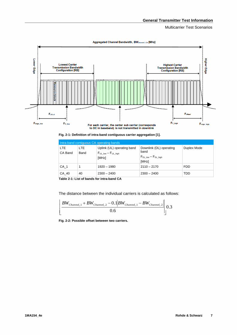
Fig. 3-5 shows the LTE demodulation measurement in the FSW.
Transmitter Tests (Chapter 6)
Basic Operation
1MA154_4e Rohde & Schwarz 18
Fig. 3-5: LTE overview in the FSW: Under Result Summary (bottom left), the test values are
summarized in scalar form.
3.1.2 SMx Vector Signal Generator
The SMx is used here to generate additional LTE or W-CDMA signals, such as
interferers or adjacent channel signals. Only the basic steps for LTE are provided here.
Several special settings are needed for the individual tests. Significantly different
settings, such as those for W-CDMA, are discussed directly in the corresponding
chapters.
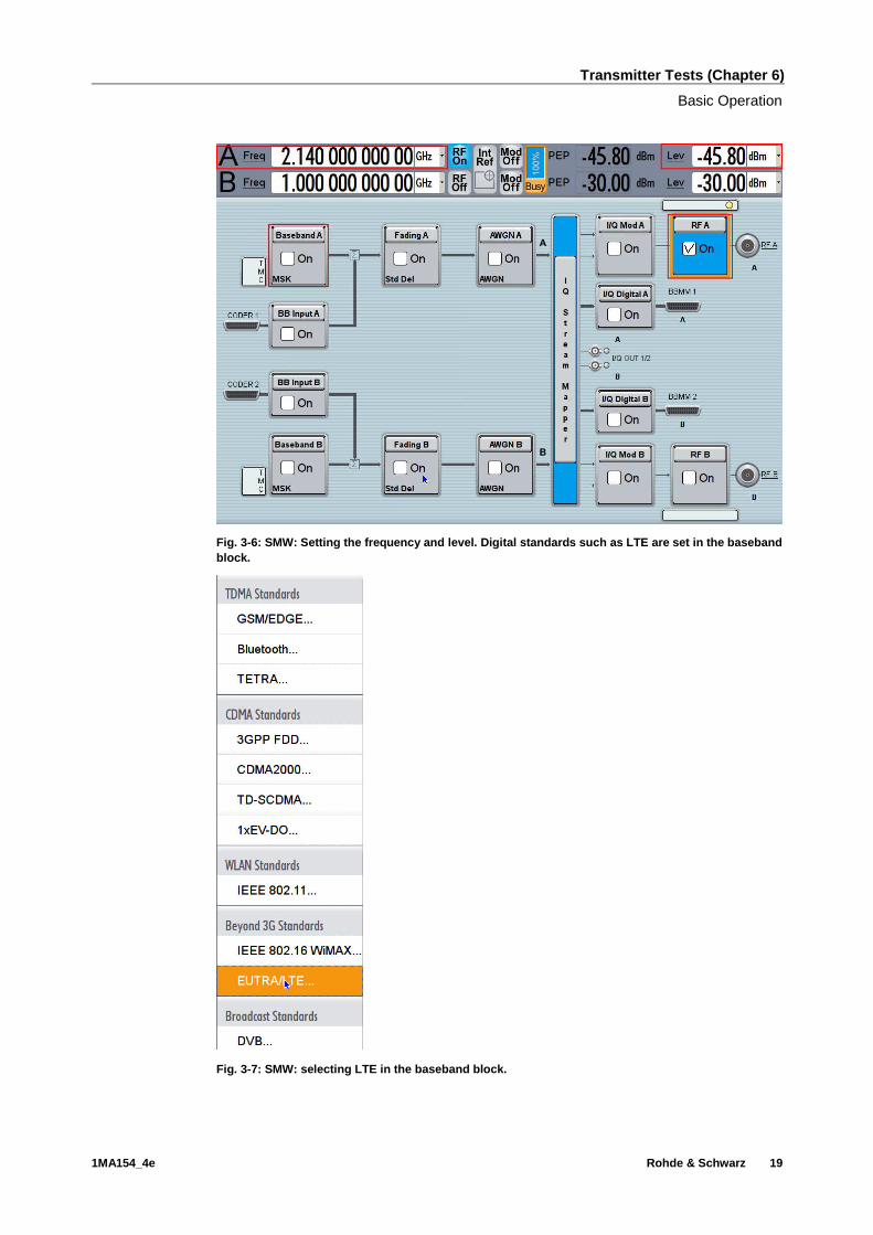
1. Set the center frequency and the levels (Freq and Lev)(Fig. 3-6)
2. Select the LTE standard in baseband block A (E-UTRA/LTE) (Fig. 3-7)
Transmitter Tests (Chapter 6)
Basic Operation
1MA154_4e Rohde & Schwarz 19
Fig. 3-6: SMW: Setting the frequency and level. Digital standards such as LTE are set in the baseband
block.
Fig. 3-7: SMW: selecting LTE in the baseband block.

Transmitter Tests (Chapter 6)
Basic Operation
1MA154_4e Rohde & Schwarz 20
3. Make the basic settings such as Duplexing (FDD or TDD) and the Link Direction
(normally Downlink (OFDMA); one test requires Uplink) (Fig. 3-8)
Fig. 3-8: SMW: general LTE settings: duplexing, link direction.
4. Select a filter. No filters are defined in the LTE. The SMx therefore offers several
optimizations (Fig. 3-9).
Fig. 3-9: SMW: selecting the LTE filter settings.

Transmitter Tests (Chapter 6)
Basic Operation
1MA154_4e Rohde & Schwarz 21
3.1.3 R&S TSrun Demo Program
This Application Note comes with a demonstration program module called LTE BS Tx
Test for the software R&S TSrun which is free of charge. The module covers all
required tests (see table below).
The LTE BS Tx Test module represents a so called test for the TSrun software. See
Section 4.1 for some important points on the basic operation of TSrun.
Each test described in this application note can be executed quickly and easily using
the module. Additional individual settings can be applied.
The program offers a straightforward user interface, and SCPI remote command
sequence export functions for integrating the necessary SCPI commands into any
user-specific test environment. A measurement report will be generated on each run. It
can be saved to a file in different formats including PDF and HTML.
Following SCPI resources are needed:
ı FSx
ı SMx
The module allows both the control of the LTE FW options on the FSx as well as the
external PC software (Fig. 3-10).
Fig. 3-10: Overview of the TSrun demo program and LTE test options. In the setup on the left, TSrun
directly controls the LTE FW option on the FSx via VISA. The setup on the right shows the control
using the external PC software. In this case, both the PC software and TSrun run on the same PC.
TSrun directly controls the PC software.
Transmitter Tests (Chapter 6)
Basic Operation
1MA154_4e Rohde & Schwarz 22
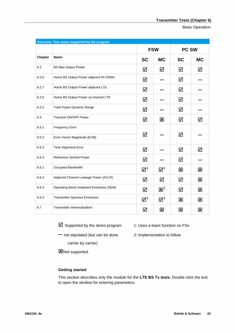
Overview: Test cases supported by the program
FSW PC SW
Chapter Name SC MC SC MC
6.2 BS Max Output Power
6.2.6 Home BS Output Power adjacent W-CDMA ─ ─
6.2.7 Home BS Output Power adjacent LTE ─ ─
6.2.6 Home BS Output Power co-channel LTE ─ ─
6.3.2 Total Power Dynamic Range ─ ─
6.4 Transmit ON/OFF Power
6.5.1 Frequency Error
─ ─
6.5.2 Error Vector Magnitude (EVM)
6.5.3 Time Alignment Error ─
6.5.4 Reference Symbol Power ─ ─
6.6.1 Occupied Bandwidth
1 1
6.6.2 Adjacent Channel Leakage Power (ACLR)
6.6.3 Operating Band Unwanted Emissions (SEM)
2
6.6.4 Transmitter Spurious Emissions
1 1
6.7 Transmitter Intermodulation
Supported by the demo program 1: Uses a basic function on FSx
─ not stipulated (but can be done 2: Implementation to follow
carrier by carrier)
Not supported.
Getting started
This section describes only the module for the LTE BS Tx tests. Double-click the test
to open the window for entering parameters.

Transmitter Tests (Chapter 6)
Basic Operation
1MA154_4e Rohde & Schwarz 23
Fig. 3-11: Full overview: setting parameters for the LTE BS Tx test.
General settings
The basic parameters are set at the top right:
ı Reset Devices: Sends a reset command to all connected instruments
ı Simulation: Generates a signal using the SMx for demonstration purposes.
ı Ext. PC-SW: Check this to use the external PC software. The PC software must
already be running and configured on the same computer. As the PC software
controls the FSx, the remote address of the FSx must be set in the PC software.
Use localhost as the remote address to control the PC software with TSrun.
ı External ref: Switches the FSx over to an external reference source (typ.
10 MHz).

Transmitter Tests (Chapter 6)
Basic Operation
1MA154_4e Rohde & Schwarz 24
Fig. 3-12: General settings.
The Attenuation section is used to enter compensations for external path
attenuations.
Fig. 3-13: Attenuation settings.
Test cases
This is the main parameter. Select the wanted test case here. All other remaining
parameters in the window are grayed out or set active based on the requirements for
the selected test case. These parameters are described in detail in the individual
sections below.
Fig. 3-14: Available test cases.

Transmitter Tests (Chapter 6)
Basic Operation
1MA154_4e Rohde & Schwarz 25
Based on the selected test case, helpful hints are provided in the Comments section
and an illustration of the basic test setup is displayed.
Fig. 3-15: Brief notes are provided in the Comments section (top right) based on the selected test
case.
Fig. 3-16: The Test Setup section (bottom right) displays a basic setup for the selected test case
along with the location of the signals in the spectrum.
Settings for measured signal
Use this section to define the basic parameters for the LTE signal to be measured:
ı Center Frequency for SC
ı The test model E-TM (E-TM1.1 is required for most test cases)
ı Duplexing Mode
ı Ref. Level: Set here the expected reference level.
ı Bandwidth

Transmitter Tests (Chapter 6)
Basic Operation
1MA154_4e Rohde & Schwarz 26
Fig. 3-17: Main settings for measured signal.
Multi-Carrier
Several tests can be carried out with MC. Selecting the Multi-Carrier option grays out
the center frequency and bandwidth parameters and allows you to enter up to ten
carriers along with their frequency and bandwidth.
Note: No logical checks of the MC settings are made. The frequencies must be
entered in rising sequence. In other words, start with TX1 for the lowest
frequency and then enter each subsequent frequency, ending with the highest
frequency.

Transmitter Tests (Chapter 6)
Base Station Output Power (Clause 6.2)
1MA154_4e Rohde & Schwarz 27
Fig. 3-18: Multicarrier settings.
More advanced settings for specific tests cases are described in the corresponding
sections below.
3.2 Base Station Output Power (Clause 6.2)
The rated output power (PRAT) of the base station is the mean power level per carrier
for BS operating in single carrier, multicarrier, or carrier aggregation configurations that
the manufacturer has declared to be available at the antenna connector during the
transmitter ON period [1].
The test is performed for SC as well as MC.
The power declared by the manufacturer must not exceed the values specified in Table
3-2. Table 3-3 shows the allowed tolerances.
Maximum rated output power for different BS classes
BS class PRAT
Wide Area BS No upper limit
Local Area BS ≤ ±24 dBm
Home BS ≤ ±20 dBm
The limit is lower by 3 dB for two ports, by 6 dB for four ports and 9 dB for eight ports for Local Area and Home BS
Table 3-2: Maximum rated output power

Transmitter Tests (Chapter 6)
Base Station Output Power (Clause 6.2)
1MA154_4e Rohde & Schwarz 28
Requirements for BS output power
Frequency range Limit
f ≤ 3.0 GHz ±2.7 dB
3.0 GHz < f ≤ 4.2 GHz ±3.0 dB
Relaxed limits apply for extreme conditions
Table 3-3: Limits for BS output power
Test setup
Fig. 3-19: Test setup for BS output power.
The DUT (base station) transmits at the declared maximum PRAT. E-TM1.1 is
required.
Procedure
The test can be performed in one of two different ways:
ı Demodulation -> Result Summary: This method uses a single data record from
the same test to obtain different values, such as EVM, frequency error, etc. The
procedure follows the basic instructions provided in Section 3.1.1. The calculated
power is displayed under Power (see Fig. 3-20).
ı Channel Power / ACLR: This method can be used to determine the output power
and the adjacent channel power simultaneously. Use as channel filter ‘Rect’.
Fig. 3-20: Output power in the result summary.
For MC scenarios, each carrier must be tested individually.
Demo program
No further special settings are needed for this test. The test is carried out as a
demodulation. The output power and other measurements are reported. In the case of
MC tests, each individual carrier is tested in sequence.

Transmitter Tests (Chapter 6)
Base Station Output Power (Clause 6.2)
1MA154_4e Rohde & Schwarz 29
Fig. 3-21: Example report for test case 6.2.
3.2.1 Home BS Output Power Measurements (Clause 6.2.6…6.2.8)
In addition to the general output power requirements, Release 10 also introduced
special tests for home BS. There is no conventional network planning for home BS.
Instead they are installed as a supplement to the various existing provider networks.
This increases the risk of interference because the home BS can transmit on adjacent
channels as well as on the same channels as an existing network. As a result, a home
BS must adapt (reduce) its output power to the specific conditions. These scenarios
are covered by the following requirements.
All three tests are required only for SC.
3.2.1.1 Home BS Output Power for Adjacent UTRA Channel Protection
(Clause 6.2.6)
The Home BS shall be capable of adjusting the transmitter output power to minimize
the interference level on the adjacent channels licensed to other operators in the same
geographical area while optimizing the Home BS coverage. These requirements are
only applicable to Home BS. The requirements in this clause are applicable for AWGN
radio propagation conditions [1].
A W-CDMA signal is provided for the test on the adjacent channel. In addition, AWGN
is simulated in the same channel of the wanted signal. The output power of the home
BS is measured at different levels of the W-CDMA and the AWGN signals. Pout must
not exceed the values in Table 3-4 for the four different input parameter sets.

Transmitter Tests (Chapter 6)
Base Station Output Power (Clause 6.2)
1MA154_4e Rohde & Schwarz 30
Fig. 3-22: Home BS with adjacent W-CDMA signal.
Requirements based on input conditions
Testcase PCPICH
(dBm)
PTotal
(dBm)
PAWGN
(dBm)
Carrier/Noise
(dB)
Pout
(dBm)
Limits
(normal conditions)
1 -80 -70 -50
- 20
≤ 20
+ 2.7 dB (f ≤ 3 GHz)
+ 3.0 dB (3 GHz ≤ f ≤ 4.2 GHz) 2 -90 -80 -60 ≤ 10
3 -100 -90 -70 ≤ 8
4 -100 -90 -50 ≤ 10
Table 3-4: Requirements for home BS with adjacent W-CDMA signal
Test setup
The following setup is used for this test. The FSx measures via a circulator the output
power (Tx) of the home BS. The SMx generates both the adjacent W-CDMA carrier
and the AWGN and feeds the signal to the home BS via a circulator.
Fig. 3-23: Test setup for a home BS with adjacent W-CDMA signal. The SMW generates both the W-
CDMA signal and the AWGN. The analyzer measures the Tx power.

Transmitter Tests (Chapter 6)
Base Station Output Power (Clause 6.2)
1MA154_4e Rohde & Schwarz 31
Overview of settings:
ı The DUT (base station) generates the wanted signal at FC with BWChannel and E-
TM1.1.
ı The SMx generates the W-CDMA signal as adjacent channel with TM1, offset Fc ±
BWChannel/2 ± 2.5 MHz (to the right or left of the wanted signal)
ı The SMx generates AWGN on the same channel as the wanted LTE signal of the
DUT. The bandwidth corresponds to BWChannel.
Procedure
The procedure is shown with an example of BWChannel = 20 MHz and Testcase 1.
1. Set the frequency of the SMx to the center frequency of the wanted signal
Generating the W-CDMA signal in the adjacent channel
2. Select W-CDMA (3GPP FDD) in baseband block A (Fig. 3-24)
Fig. 3-24: SMW: selecting the 3GPP FDD (W-CDMA) signal in the baseband block.
3. Go to the Basestations tab (Fig. 3-25)

Transmitter Tests (Chapter 6)
Base Station Output Power (Clause 6.2)
1MA154_4e Rohde & Schwarz 32
Fig. 3-25: SMW: W-CDMA base stations.
4. Click Test Setups/Models
5. Select a TM1 (any number of channels) (Fig. 3-26)
Fig. 3-26: SMW: selecting TM1 for W-CDMA.
6. Switch on the baseband and set the frequency offset of the wanted LTE carrier in
order to set the W-CDMA carrier in the adjacent channel: Foff = BWLTE / 2 + 2.5
MHz (example: Foff = 20 MHz / 2 + 2.5 MHz = 12.5 MHz) (Fig. 3-27 and Fig. 3-28)
Fig. 3-27: SMW: offsets in the baseband.

Transmitter Tests (Chapter 6)
Base Station Output Power (Clause 6.2)
1MA154_4e Rohde & Schwarz 33
Fig. 3-28: Setting the frequency offset for the W-CDMA carrier (e.g. 12.5 MHz).
7. In the SMx, the default level for the P-CPICH is –10 dB relative to the total level of
the SMx. Set the total level accordingly (example: Test Case 1: PCPICH = –80 dBm:
Ptotal = –80 dBm – (–10 dB) = –70 dBm)
Fig. 3-29: SMW: CPICH level in W-CDMA.
AWGN
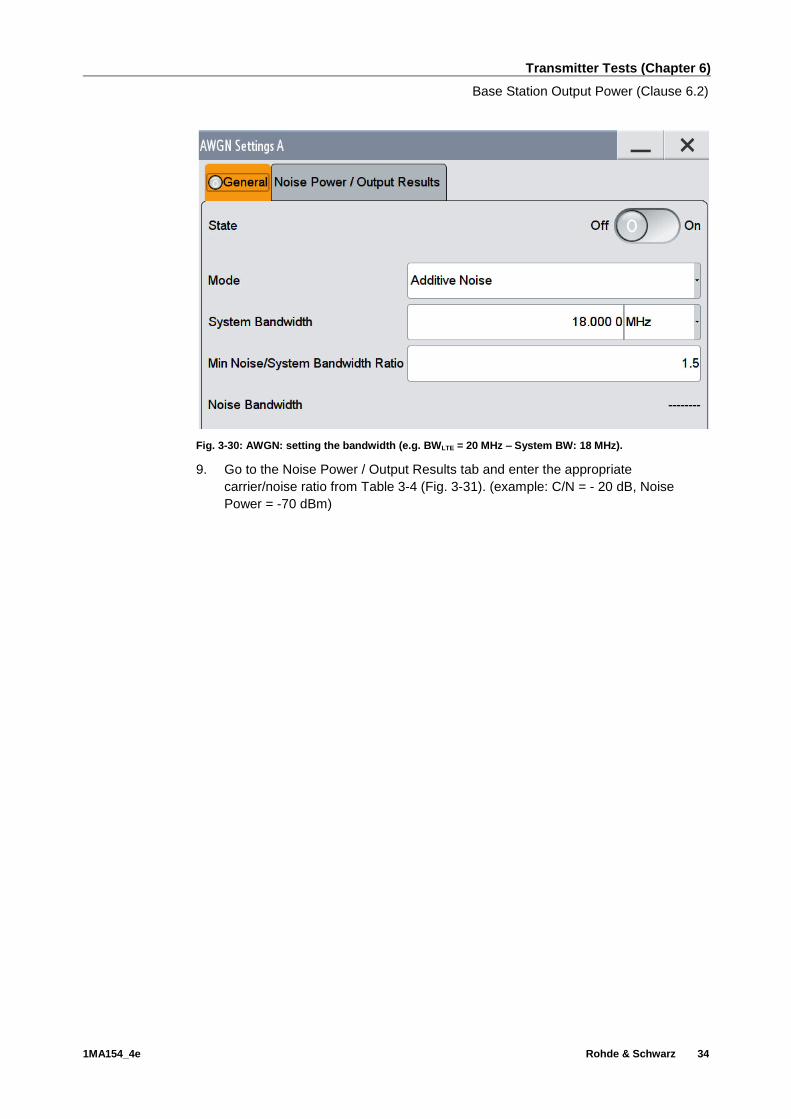
8. Click the AWGN block and set the bandwidths (Fig. 3-30).(example: System BW =
18 MHz)
Transmitter Tests (Chapter 6)
Base Station Output Power (Clause 6.2)
1MA154_4e Rohde & Schwarz 34
Fig. 3-30: AWGN: setting the bandwidth (e.g. BWLTE = 20 MHz – System BW: 18 MHz).
9. Go to the Noise Power / Output Results tab and enter the appropriate
carrier/noise ratio from Table 3-4 (Fig. 3-31). (example: C/N = - 20 dB, Noise
Power = -70 dBm)

Transmitter Tests (Chapter 6)
Base Station Output Power (Clause 6.2)
1MA154_4e Rohde & Schwarz 35
Fig. 3-31: AWGN: Setting the noise power relative to the carrier power via the carrier/noise ratio (e.g.
the carrier power is –70 dBm, so the noise power in test case 1 should be –50 dBm: –70 dB – (–50
dB) = –20 dB).
Fig. 3-32: Overview of the SMW for W-CDMA with AWGN. The W-CDMA signal is offset to the
adjacent channel in the baseband.
Measurement with FSx
Measure the Pout of the home BS for all test cases (Table 3-4) and both offsets.
The test can be performed in one of two different ways:
ı Demodulation -> Result Summary: This method uses a single data record from
the same test to obtain different values, such as EVM, frequency error, etc. The

Transmitter Tests (Chapter 6)
Base Station Output Power (Clause 6.2)
1MA154_4e Rohde & Schwarz 36
procedure follows the basic instructions provided in Section 3.1.1. The calculated
power is displayed under Power (see Fig. 3-33).
ı Channel Power / ACLR: This method can be used to determine the output power
and the adjacent channel power simultaneously. Use as channel filter ‘Rect’.
Fig. 3-33: Output power in der result summary.
Demo program
For this test, additional parameters must be defined. The test is carried out as a
demodulation measurement. The output power and other measurements are reported.
Fig. 3-34: Special settings for output power with adjacent W-CDMA.
The level for the adjacent W-CDMA carrier and AWGN can be entered directly. Please
note the settings from the specification listed in Table 3-4.
By default, the W-CDMA carrier is set to the right of the wanted signal. Checking
mirror sets it to the left.

Transmitter Tests (Chapter 6)
Base Station Output Power (Clause 6.2)
1MA154_4e Rohde & Schwarz 37
Fig. 3-35: Example report for test case 6.2.6.
3.2.1.2 Home BS Output Power for Adjacent E-UTRA Channel Protection
(Clause 6.2.7)
The Home BS shall be capable of adjusting the transmitter output power to minimize
the interference level on the adjacent channels licensed to other operators in the same
geographical area while optimizing the Home BS coverage. These requirements are
only applicable to Home BS. The requirements in this clause are applicable for AWGN
radio propagation conditions [1].
Fig. 3-36: Home BS with adjacent LTE signal.
An LTE signal is provided for the test on the adjacent channel. AWGN is also
simulated in the same channel of the wanted signal. The output power measurements

Transmitter Tests (Chapter 6)
Base Station Output Power (Clause 6.2)
1MA154_4e Rohde & Schwarz 38
for the home BS is to be measured at different levels of the LTE signal and the AWGN.
Pout must not exceed the values in Table 3-5 for the four different input parameter sets.
In the specification, the level of the adjacent LTE signal is set via the reference symbol
power using the formula . Because the required test model E-
TM1.1 assigns all RBs, the total level (Ptotal) can be entered directly and set on the
SMx.
Requirements based on input conditions for adjacent LTE
Test case
Ptotal
(dBm)
PAWGN
(dBm)
Carrier/Noise
(dB)
Pout
(dBm)
Limits
(normal conditions)
1 –65 –50 - 15 ≤ 20
+2.7 dB (f ≤ 3 GHz)
+3.0 dB (3 GHz ≤ f ≤ 4.2 GHz) 2 –75 –60 - 15 ≤ 10
3 –90 –70 - 20 ≤ 8
4 –90 –50 - 40 ≤ 10
Table 3-5: Requirements for home BS with adjacent LTE signal
Test setup
The following setup is used for this test. The FSx measures via a circulator the output
power (Tx) of the home BS. The SMx provides both the adjacent LTE carrier and the
AWGN and feeds the signal to the home BS via a circulator.
Fig. 3-37: Test setup for a home BS with adjacent LTE signal. The SMW generates both the LTE
signal and the AWGN.
Overview of settings:
ı The DUT (base station) generates the wanted signal at FC with BWChannel and E-
TM1.1.
ı The SMx generates the LTE signal as an adjacent channel with the same
BWChannel and E-TM1.1, offset Fc ± BWChannel (to the right or left of the wanted
signal)
ı The SMx generates AWGN on the same channel as the wanted LTE signal of the
DUT. The bandwidth corresponds to BWChannel.
RB
sc
DL
RB NN 10log10

Transmitter Tests (Chapter 6)
Base Station Output Power (Clause 6.2)
1MA154_4e Rohde & Schwarz 39
Procedure
The procedure is shown with an example of BWChannel = 20 MHz and Testcase 1.
1. Set the frequency of the SMx to the center frequency of the wanted signal
Generating the adjacent LTE signal
2. Generate an LTE signal that is equivalent to the wanted signal (see 3.1.2)
3. Select test model E-TM1.1. (Fig. 3-38)(example E-TM1.1 with 20 MHz)
Fig. 3-38: Selecting the test model in LTE.
4. Switch on the baseband and set the frequency offset of the wanted LTE carrier in
order to set the LTE carrier in the adjacent channel: Foff = BWLTE (example.
20 MHz) (Fig. 3-39 and Fig. 3-40)
Fig. 3-39: SMW: offsets in the baseband.
Transmitter Tests (Chapter 6)
Base Station Output Power (Clause 6.2)
1MA154_4e Rohde & Schwarz 40
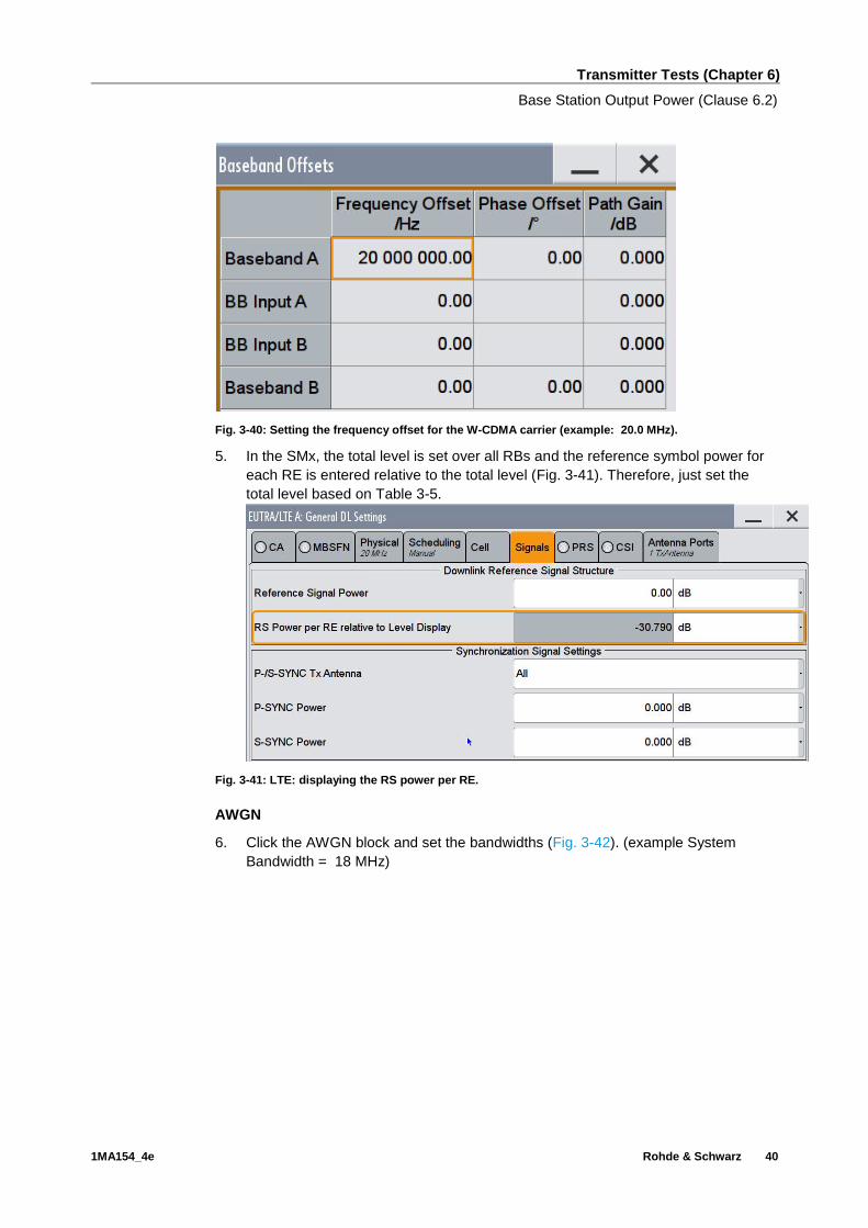
Fig. 3-40: Setting the frequency offset for the W-CDMA carrier (example: 20.0 MHz).
5. In the SMx, the total level is set over all RBs and the reference symbol power for
each RE is entered relative to the total level (Fig. 3-41). Therefore, just set the
total level based on Table 3-5.
Fig. 3-41: LTE: displaying the RS power per RE.
AWGN
6. Click the AWGN block and set the bandwidths (Fig. 3-42). (example System
Bandwidth = 18 MHz)

Transmitter Tests (Chapter 6)
Base Station Output Power (Clause 6.2)
1MA154_4e Rohde & Schwarz 41
Fig. 3-42: AWGN: setting the bandwidth (example: BWLTE = 20 MHz -> System BW: 18 MHz).
7. Go to the Noise Power / Output Results tab and enter the appropriate
carrier/noise ratio from (Fig. 3-43).
Fig. 3-43: AWGN: Setting the noise power relative to the carrier power via the carrier/noise ratio
(example: the carrier power is –65 dBm, so the noise power in test case 1 should be –50 dBm: –65
dB – (–50 dB) = –15 dB).

Transmitter Tests (Chapter 6)
Base Station Output Power (Clause 6.2)
1MA154_4e Rohde & Schwarz 42
Measurement with FSx
Measure the Pout of the home BS for all test cases (Table 3-5) and both offsets.
The test can be performed in one of two different ways:
ı Demodulation -> Result Summary: This method uses a single data record from
the same test to obtain different values, such as EVM, frequency error, etc. The
procedure follows the basic instructions provided in Section 3.1.1. The calculated
power is displayed under Power (see Fig. 3-44).
ı Channel Power / ACLR: This method can be used to determine the output power
and the adjacent channel power simultaneously. Use as channel filter ‘Rect’.
Fig. 3-44: Output power in the result summary.
Demo program
For this test, additional parameters must be defined. The test is carried out as a
demodulation measurement. The output power and other measurements are reported.
Fig. 3-45: Special settings for output power with adjacent LTE.
The level for the adjacent LTE carrier and AWGN can be entered directly. Please note
the settings from the specification listed in Table 3-5.
By default, the LTE carrier is set to the right of the wanted signal. Checking mirror
sets it to the left.

Transmitter Tests (Chapter 6)
Base Station Output Power (Clause 6.2)
1MA154_4e Rohde & Schwarz 43
Fig. 3-46: Example report for test case 6.2.7.
3.2.1.3 Home BS Output Power for Co-Channel E-UTRA Protection (Clause
6.2.8)
To minimize the co-channel DL interference to non-CSG macro UEs operating in close
proximity while optimizing the CSG Home BS coverage, Home BS may adjust its
output power according to the requirements set out in this clause. These requirements
are only applicable to Home BS. The requirements in this clause are applicable for
AWGN radio propagation conditions [1].
A downlink LTE signal with different levels is provided for the test on the same
channel. AWGN is also simulated in the same channel. The output power for the home
BS is to be measured. For so called option 2, an LTE signal is additionally generated
for the uplink.

Transmitter Tests (Chapter 6)
Base Station Output Power (Clause 6.2)
1MA154_4e Rohde & Schwarz 44
Fig. 3-47: Home BS with co-channel LTE signal.
Because no configurations are defined for the co-channel LTE signals, the test
parameters can vary widely:
Home BS output power for co-channel LTE
Input Conditions Pout
Ioh (DL) > CRS Ês + 10log10(
DLRBN RB
scN) + 30 dB
≤ 10 dBm
Ioh (DL) ≤ CRS Ês + 10log10(
DLRBN RB
scN) + 30 dB
≤ max (- 10 dBm, min (Pmax, CRS Ês +
10log10(
DLRBN RB
scN) + 30 dB ))
Table 3-6: Home BS output power for co-channel E-UTRA channel protection [1]
Requirements based on input conditions for co-channel LTE
Test case PtotalDL
(dBm)
PAWGN
(dBm)
PtotalUL
(dBm)
Pout
(dBm)
Limits
(normal conditions)
1
–10 – 10log10(
DLRBN RB
scN)
–50
–98
See condition defined in table
3-6
+2.7 dB (f ≤ 3 GHz)
+3.0 dB (3 GHz ≤ f ≤ 4.2 GHz) 2
–20 – 10log10(
DLRBN RB
scN)
–60
3
–40 – 10log10(
DLRBN RB
scN)
–70
4
–90 – 10log10(
DLRBN RB
scN)
–50
Table 3-7: Requirements based on input conditions for co-channel LTE
The example below uses E-TM1.1 for the downlink signal and FRC1 for the uplink
signal, which simplifies the settings (see Table 3-8).

Transmitter Tests (Chapter 6)
Base Station Output Power (Clause 6.2)
1MA154_4e Rohde & Schwarz 45
Test setup
The following setup is used for this test. The FSx measures via circulator the output
power (Tx) of the home BS. The SMx provides both the adjacent downlink LTE carrier
and the AWGN and feeds the signal to the home BS via a circulator. For option 2, the
SMx additionally provides the LTE uplink signal via the second path.
Fig. 3-48: Test setup for a home BS with co-channel LTE signal.The SMW generates both the LTE
signal and the AWGN.
Overview of settings:
ı The DUT (base station) generates the wanted signal at FC with BWChannel and E-
TM1.1.
ı The SMx generates the co-channel LTE downlink signal with the same BWChannel.
There is no special configuration required.
ı The SMx generates AWGN on the same channel as the wanted LTE signal of the
DUT. The bandwidth corresponds to BWChannel.
ı For option 2, the SMx additionally generates an LTE uplink signal. There is no
special configuration required.
Procedure
The procedure is shown with an example of BWChannel = 20 MHz and Testcase 1. To
simplify the settings, E-TM1.1 is used (see Table 3-8).
1. Set the frequency of the SMx to the center frequency of the wanted signal
Generating the downlink LTE signal
2. Generate an LTE signal that is equivalent to the wanted signal (see 3.1.2)
3. Select test model E-TM1.1. (Fig. 3-49) (example with 20 MHz)

Transmitter Tests (Chapter 6)
Base Station Output Power (Clause 6.2)
1MA154_4e Rohde & Schwarz 46
Fig. 3-49: Selecting the test model in LTE.
4. In the SMx, the total level is set over all RBs and the reference symbol power for
each RE is entered relative to the total level (Fig. 3-50). Therefore, set the total
level based on Table 3-8.
Fig. 3-50: LTE: displaying the RS power per RE.
AWGN
5. Click the AWGN block and set the bandwidths (Fig. 3-51). (example: System BW
= 18 MHz)
Transmitter Tests (Chapter 6)
Base Station Output Power (Clause 6.2)
1MA154_4e Rohde & Schwarz 47
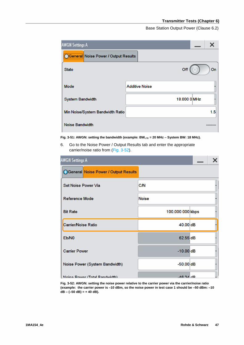
Fig. 3-51: AWGN: setting the bandwidth (example: BWLTE = 20 MHz – System BW: 18 MHz).
6. Go to the Noise Power / Output Results tab and enter the appropriate
carrier/noise ratio from (Fig. 3-52).
Fig. 3-52: AWGN: setting the noise power relative to the carrier power via the carrier/noise ratio
(example: the carrier power is –10 dBm, so the noise power in test case 1 should be –50 dBm: –10
dB – (–50 dB) = + 40 dB).

Transmitter Tests (Chapter 6)
Base Station Output Power (Clause 6.2)
1MA154_4e Rohde & Schwarz 48
Option 2 only: Generating the uplink LTE signal
7. Set the link direction to Uplink (SC-FDMA).
8. Set the corresponding bandwidth.
Fig. 3-53: Setting the uplink in the LTE.
Fig. 3-54: Setting the bandwidth BW in the uplink.
9. Click UE1.
10. Select the corresponding FRC and switch FRC state On. (example: FRC A3-7)

Transmitter Tests (Chapter 6)
Base Station Output Power (Clause 6.2)
1MA154_4e Rohde & Schwarz 49
Fig. 3-55: Displaying the simulated UE1. The UE parameters can be entered with a mouse click.
Fig. 3-56: Setting the FRC for the UE. (example: A3-7)
Measurement with FSx
If E-TM1.1 is used for the wanted signal, Table 3-7 is simplified as follows:
Requirements based on input conditions for adjacent LTE
Test case
PtotalDL
(dBm)
PAWGN
(dBm)
Carrier/Noise
(dB)
PtotalUL
(dBm)
Pout
(dBm)
Limits
(normal conditions)
1 –10 –50 + 40
–98
≤ 20
+2.7 dB (f ≤ 3 GHz)
+3.0 dB (3 GHz ≤ f ≤ 4.2 GHz) 2 –20 –60 + 40 ≤ 10
3 –40 –70 + 30 ≤ Pmax
4 –90 –50 - 40 ≤ 10
Table 3-8: Requirements for home BS with co-channel LTE signal for an example using E-TM1.1

Transmitter Tests (Chapter 6)
Base Station Output Power (Clause 6.2)
1MA154_4e Rohde & Schwarz 50
Measure the Pout of the home BS for all test cases (Table 3-8) and both offsets.
The test can be performed in one of two different ways:
ı Demodulation -> Result Summary: This method uses a single data record from
the same test to obtain different values, such as EVM, frequency error, etc. The
procedure follows the basic instructions provided in Section 3.1.1. The calculated
power is displayed under Power (see Fig. 3-57).
ı Channel Power / ACLR: This method can be used to determine the output power
and the adjacent channel power simultaneously. Use as channel filter ‘Rect’.
Fig. 3-57: Output power in the result summary.
Demo program
For this test, additional the parameters must be defined. The test is carried out as a
demodulation measurement. The output power and other measurements are reported.
Fig. 3-58: Special settings for output power with co-channel LTE.
The level for the co-channel LTE carrier and AWGN can be entered directly. The uplink
level is needed only for option 2. Please note the settings from the specification listed
in Table 3-7.

Transmitter Tests (Chapter 6)
Output Power Dynamics (Clause 6.3)
1MA154_4e Rohde & Schwarz 51
Fig. 3-59: Example report for test case 6.2.8.
3.3 Output Power Dynamics (Clause 6.3)
3.3.1 Total Power Dynamic Range (Clause 6.3.2)
The total power dynamic range is the difference between the maximum and the
minimum transmit power of an OFDM symbol for a specified reference condition [1].
The measured OFDM symbols shall not contain RS, PBCH or synchronization signals.
The test software includes this automatically in the calculation and displays the result
as OSTP (OFDM symbol transmit power) in the Result Summary. The test is
performed only for SC.
Dynamic range requirements
Channel bandwidth (MHz) Power dynamic range
1.4 7.3
3 11.3
5 13.5
10 16.5
15 18.3
20 19.6
Table 3-9: BS total power dynamic range, paired spectrum

Transmitter Tests (Chapter 6)
Output Power Dynamics (Clause 6.3)
1MA154_4e Rohde & Schwarz 52
Test setup
Fig. 3-60: Test setup for BS output power.
The DUT (base station) transmits at the declared maximum PRAT sequentially with
two different configurations.
ı E-TM3.1
ı E-TM2
Procedure
The test can be performed in one of two different ways:
ı Demodulation -> Result Summary: This method uses a single data record from
the same test to obtain different values, such as EVM, frequency error, etc. The
procedure follows the basic instructions provided in Section 3.1.1. The calculated
power is displayed under Power (see Fig. 3-61).
ı Channel Power / ACLR: This method can be used to determine the output power
and the adjacent channel power simultaneously. Use as channel filter ‘Rect’.
Fig. 3-61: Result summary: OSTP (OFDM symbol transmit power).
Two measurements are taken. The total power dynamic range is the difference
between the two measurements OSTPE-TM3.1 – OSTPE-TM2.
Demo program
No further special settings are needed for this test. The test is carried out as a
demodulation measurement. Two measurements for the different TMs are performed
one after the other. The difference is reported as Dynamic range. A dialog box tells the
user when to change to the next TM. Simulation is not supported.

Transmitter Tests (Chapter 6)
Transmit ON/OFF Power (Clause 6.4)
1MA154_4e Rohde & Schwarz 53
Fig. 3-62: Example report for test case 6.3.1.
3.4 Transmit ON/OFF Power (Clause 6.4)
Transmitter OFF power is defined as the mean power measured over 70 µs filtered
with a square filter of bandwidth that is equal to the transmission bandwidth
configuration of the base station (BWConfig) centered on the assigned channel
frequency during the transmitter OFF period. [1]
For BS supporting intra-band contiguous CA, the transmitter OFF power is defined as
the mean power measured over 70 us filtered with a square filter of bandwidth equal to
the aggregated channel bandwidth BWChannel_CA centered on (Fedge_high+Fedge_low)/2
during the transmitter OFF period. [1]
This test applies only for TDD and is defined for both SC and MC.
Fig. 3-63 shows the definition of the ranges and Table 3-10 lists the limits.
OFF-to-ON
period
ON-to-OFF
period
Fig. 3-63: Definition of transmitter ON and OFF periods [1].
Transmitter OFF power limit
Frequency range Limit
f ≤ 3 GHz -83 dBm/MHz
3 GHz < f ≤ 4.2 GHz -82.5 dBm/MHz
Table 3-10: Transmitter OFF limits
.

Transmitter Tests (Chapter 6)
Transmit ON/OFF Power (Clause 6.4)
1MA154_4e Rohde & Schwarz 54
Test setup
Additional hardware is required for this test. An RF limiter is used to limit the power
received at the analyzer during the transmitter ON periods. This enables the full
dynamic range for the measurements in the OFF periods. In addition, an attenuator is
used to absorb the reflected power for limiters without optimal VSWR.
Fig. 3-64: Test setup: transmit ON/OFF.
The DUT (base station) generates the wanted signal at FC with BWChannel and E-TM1.1.
Procedure
The ON/OFF measurement for single carrier is included in all options. The ability to
test multicarriers is currently available only using the external LTE PC SW.
1. In the software, go to MEAS - PVT and select the ON/OFF POWER
measurement. Duplexing may already be set up to TDD. The TDD configuration
must be defined (UL/DL configuration and special subframe). These parameters
are automatically set correctly when the test module (E-TM) is selected.
2. You can change the settings under GENERAL SETTINGS (see Fig. 3-65). For
tests with carrier aggregation, enter the frequency range (Lower and Higher
Edge) (BWChannel_CA) for the test. Under (Center) Frequency, select the frequency
of one of the carriers to be measured. The Number of Frames is preset to 50
frames per the specification. Press the Noise Correction button to perform an
additional measurement to enable more dynamic by subtraction of the noise. An
external trigger is to be used for MC tests. To do this, press the ADJ Timing
button before starting the test. This automatically sets the appropriate timings for
the actual measurement.
3. The limit can be modified via an XML file (see the manual)

Transmitter Tests (Chapter 6)
Transmit ON/OFF Power (Clause 6.4)
1MA154_4e Rohde & Schwarz 55
Fig. 3-65: Settings for ON/OFF POWER.

Transmitter Tests (Chapter 6)
Transmit ON/OFF Power (Clause 6.4)
1MA154_4e Rohde & Schwarz 56
Fig. 3-66 displays the On/Off measurement using the PC SW as an example.
Fig. 3-66: ON/OFF power measurement: At the top is a display of the measured OFF power and the
transition period times. At the bottom are the progression versus time and the limit check.
Demo program
This test is possible for TDD only. The measured OFF power is displayed. By default,
the test uses Noise Cancellation. At present, the measurement with the PC SW uses
one frame only, while the FSW option measurement uses 50 frames. The times for the
Rising and Falling Period are also measured and reported.
Fig. 3-67: Noise cancellation at transmit On/Off.

Transmitter Tests (Chapter 6)
Transmitted Signal Quality (Clause 6.5)
1MA154_4e Rohde & Schwarz 57
Fig. 3-68: Example report for test case 6.4.
3.5 Transmitted Signal Quality (Clause 6.5)
3.5.1 Frequency Error (Clause 6.5.1) and Error Vector Magnitude (Clause
6.5.2)
The two tests are defined only for SC.
Frequency error is the measure of the difference between the actual BS transmit
frequency and the assigned frequency [1].
Table 3-11 shows the limits for the various base stations.
Frequency error requirements
BS class Accuracy
Wide Area BS ± (0.05 ppm + 12 Hz)
Local Area BS ± (0.1 ppm + 12 Hz)
Home BS ± (0.25 ppm + 12 Hz)
Table 3-11: Frequency error requirements [1]
For this measurement the FSx must be synchronized via External Reference to the
basestation under test.
The error vector magnitude is a measure of the difference between the ideal symbols
and the measured symbols after the equalization. This difference is called the error
vector. The EVM result is defined as the square root of the ratio of the mean error
vector power to the mean reference power expressed in percent [1].
Table 3-12 shows the limits for the various modulation modes.

Transmitter Tests (Chapter 6)
Transmitted Signal Quality (Clause 6.5)
1MA154_4e Rohde & Schwarz 58
EVM requirements
Modulation scheme PDSCH EVM [%]
QPSK 18.5
16QAM 13.5
64QAM 9
Table 3-12: EVM requirements [1]
Test setup
Fig. 3-69: Test setup for BS output powerThe DUT (base station) transmits with the declared
maximum PRAT. The following configurations are specified:
ı E-TM3.1
ı E-TM3.2
ı E-TM3.3
ı E-TM2
Procedure
The signal is demodulated for the test. The test results are displayed in a scalar
overview under RESULT SUMMARY. This method uses a single data record from the
same test to obtain different values, such as power, crest factor, etc. The procedure
follows the basic instructions provided in Section 3.1.1. The calculated power is
displayed under EVM PDSCH and Frequency Error (see Fig. 3-70).
Fig. 3-70: Result summary: EVM and frequency error.
In addition to the required measured values for frequency errors and EVM, the
summary also includes results such as sample error, I/Q imbalance, etc.

Transmitter Tests (Chapter 6)
Transmitted Signal Quality (Clause 6.5)
1MA154_4e Rohde & Schwarz 59
Demo program
No further special settings are needed for this test. The test is carried out as a
demodulation measurement. The frequency error and EVM are reported. In the case of
MC tests, each individual carrier is measured in sequence.
Fig. 3-71: Example report for test case 6.5.1.
3.5.2 Time Alignment Error (Clause 6.5.3)
Frames of the LTE signals present at the BS transmitter antenna ports are not perfectly
aligned in time. In relation to each other, the RF signals present at the BS transmitter
antenna ports experience certain timing differences. [1]
Time alignment error (TAE) is defined as the largest timing difference between any two
signals. This test is only applicable for base stations supporting TX diversity, MIMO
transmission, carrier aggregation and their combinations.
The test is performed for SC as well as MC.
Table 3-13 lists the limits for various combinations.
Time alignment error limits
Transmission combination Limit
MIMO/TX diversity single carrier 90 ns
Intra-band CA with or without MIMO or TX diversity 155 ns
Inter-band CA with or without MIMO or TX diversity 285 ns
Table 3-13: Time alignment error limits [1]
Demo program
No further special settings are needed for this test. Take note of the special test setup.
The difference is output in ns.

Transmitter Tests (Chapter 6)
Transmitted Signal Quality (Clause 6.5)
1MA154_4e Rohde & Schwarz 60
Fig. 3-72: Example report for test case 6.5.3.
3.5.2.1 Single Carrier (MIMO, Tx Diversity)
Test setup
The following setup is used for this test. The antennas to be measured are connected
via a hybrid coupler. The FSx is connected via an attenuator. To achieve precise
measurements, the RF cables being used should be equal in electrical length.
Fig. 3-73: Test setup: time alignment for SC.
Procedure
Up to 4 antennas can be measured in parallel. The measurement is taken on the
reference signals (RS) of the individual antennas, and PDSCHs are ignored.
1. Start the test using MEAS and "Time Alignment"
2. The measurement is always relative to one reference antenna. The antenna can
be changed under "Reference Antenna".

Transmitter Tests (Chapter 6)
Transmitted Signal Quality (Clause 6.5)
1MA154_4e Rohde & Schwarz 61
Fig. 3-74: Time alignment: Up to 4 antennas can be measured. The measurement is displayed relative
to one selectable reference antenna.
3.5.2.2 Multicarrier (CA)
The CA measurement (including intra-band) can be performed in one of two different
ways:
ı PC SW with RTO: Simple, precise measurement, in parallel with MIMO
ı FSx with external trigger: Two-shot measurement, making the test less precise
than with the RTO
PC SW with RTO
Test setup
Fig. 3-75: Test setup for the time alignment error measurement for CA with RTO. The two carriers are
measured simultaneously with one RTO.

Transmitter Tests (Chapter 6)
Transmitted Signal Quality (Clause 6.5)
1MA154_4e Rohde & Schwarz 62
Procedure
1. In the PC SW, go to General Settings. In the Time Alignment Measurement
Settings section, set the Num of Component Carrier field to 2 and then set the
corresponding frequency of the second carrier in the (CC2 Frequency) field (Fig.
3-76).
2. Additional settings for the second carrier can be made under CC2 DEMOD
SETTINGS.
3. Start the test (Fig. 3-77)
Fig. 3-76: Settings for time alignment measurements with CA.
Transmitter Tests (Chapter 6)
Transmitted Signal Quality (Clause 6.5)
1MA154_4e Rohde & Schwarz 63
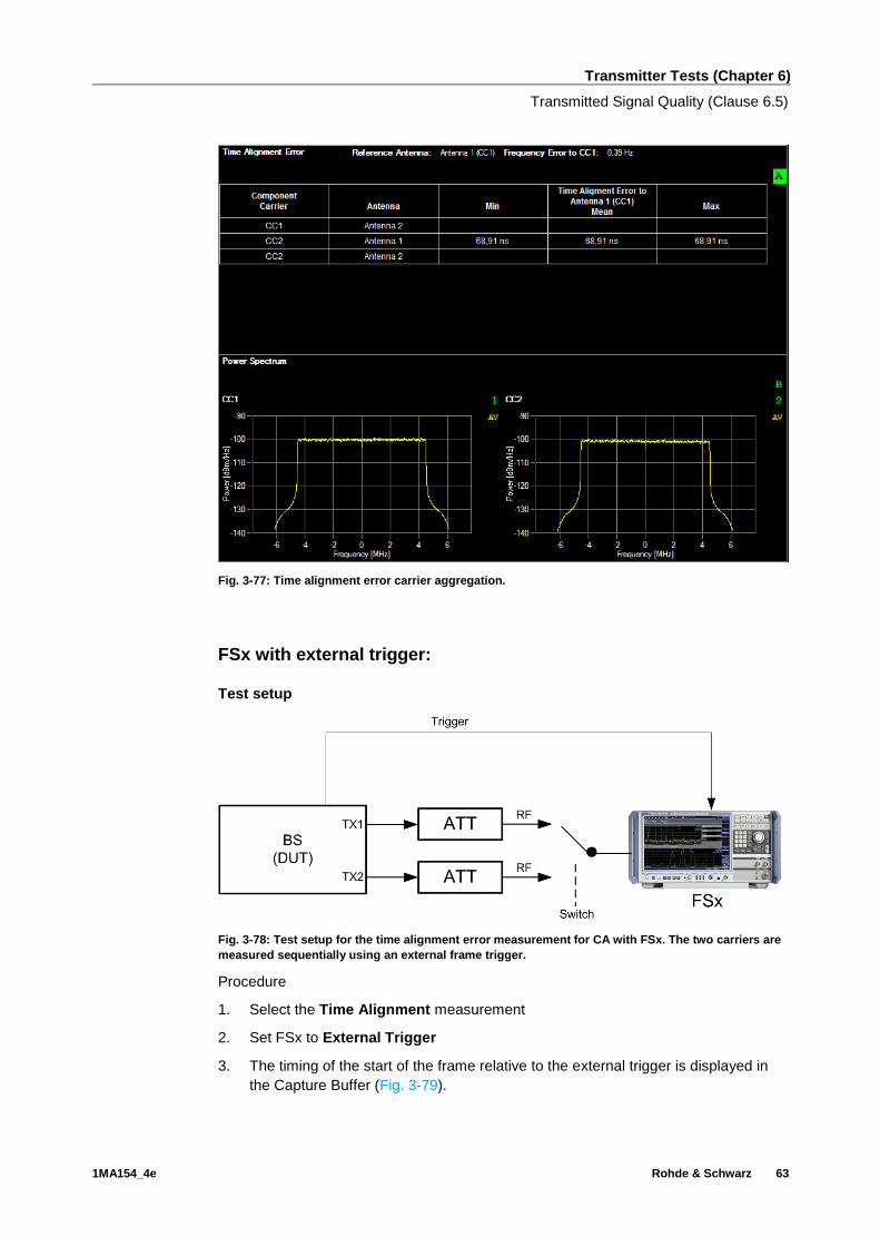
Fig. 3-77: Time alignment error carrier aggregation.
FSx with external trigger:
Test setup
Fig. 3-78: Test setup for the time alignment error measurement for CA with FSx. The two carriers are
measured sequentially using an external frame trigger.
Procedure
1. Select the Time Alignment measurement
2. Set FSx to External Trigger
3. The timing of the start of the frame relative to the external trigger is displayed in
the Capture Buffer (Fig. 3-79).

Transmitter Tests (Chapter 6)
Transmitted Signal Quality (Clause 6.5)
1MA154_4e Rohde & Schwarz 64
Fig. 3-79: Measuring the offset to the external trigger.
4. Repeat the measurement for the second carrier and calculate the difference for
the two measured values.
3.5.3 DL RS Power (Clause 6.5.4)
DL RS power is the resource element power of downlink reference symbol. The
absolute DL RS power is indicated on the downlink shared channel (DL-SCH) in
Layer 2.
The test is defined only for SC.
Table 3-14 lists the tolerances dependent on the frequency range.
DL RS power
Frequency range Deviation to indicated power
≤ 3 GHz ± 2.9 dB
3 GHz ≤ f ≤ 4.2 GHz ± 3.2 dB
Table 3-14: DL RS power requirements
Test setup
Fig. 3-80: Test setup for BS output power.
The DUT (base station) transmits with the declared maximum PRAT. E-TM1.1 is
required.
Procedure
The signal is demodulated for the test. The test results are displayed in a scalar
overview under RESULT SUMMARY. This method uses a single data record from the
same test to obtain different values, such as power, crest factor, etc. The procedure
follows the basic instructions provided in Section 3.1.1. The calculated power is
displayed under RSTP (see Fig. 3-81).

Transmitter Tests (Chapter 6)
Unwanted Emissions (Clause 6.6)
1MA154_4e Rohde & Schwarz 65
Fig. 3-81: Result summary: display of the DL RS power (RSTP).
Demo program
No further special settings are needed for this test. The test is carried out as a
demodulation measurement. The reference symbol power is reported.
Fig. 3-82: Example report for test case 6.5.4.
3.6 Unwanted Emissions (Clause 6.6)
Unwanted emissions consist of out-of-band emissions and spurious emissions. Out-of-
band emissions are unwanted emissions immediately outside the channel bandwidth
resulting from the modulation process and non-linearity in the transmitter but excluding
spurious emissions. Spurious emissions are emissions which are caused by unwanted
transmitter effects such as harmonics emission, parasitic emission, intermodulation
products and frequency conversion products, but exclude out-of-band emissions [1].

Transmitter Tests (Chapter 6)
Unwanted Emissions (Clause 6.6)
1MA154_4e Rohde & Schwarz 66
3.6.1 Occupied Bandwidth (Clause 6.6.1)
Occupied Bandwidth is the width of a frequency band such that, below the lower and
above the upper frequency limits, the mean powers emitted are each equal to a
specified percentage β/2 of the total mean transmitted power. It defines the spectral
properties of emission in a simple manner.
The value of β/2 shall be taken as 0.5%. This results in a power bandwidth of 99%.
The measurement of the spectrum is carried out with resolution bandwidth (RBW) of
30 kHz or less and the measurement points mentioned in Table 3-15.
Span and measurement points for OBW measurement
Channel bandwidth [MHz] 1.4 3 5 10 15 20 >20
Span [MHz] 10 10 10 20 30 40 CAChannelBW _*2
Minimum number of measurement points
1429 227 400 400 400 400
kHz
BW CAChannel
100
*2 _
Table 3-15: OBW: span and measurement points
The measured bandwidth (OBW) shall be smaller than the nominal bandwidth (see
Table 3-15, top row). For multicarrier scenarios, the OBW should be smaller than the
aggregated bandwidth. Multiple combinations shall be tested as described in Section
4.10.2 [1].
Test setup
Fig. 3-83: Test setup for BS output power.
The DUT (base station) transmits with the declared maximum PRAT. E-TM1.1 is
required.
The general base unit function "OBW" is used for the test. For TDD signals, the trigger
must be set to external.
Procedure (example: 10 MHz bandwidth)
1. Press MODE and then select Spectrum
2. Press MEAS and select OBW
3. Verify the %Power Bandwidth default setting of 99%

Transmitter Tests (Chapter 6)
Unwanted Emissions (Clause 6.6)
1MA154_4e Rohde & Schwarz 67
4. Set the Channel Bandwidth (example: 10 MHz)
5. Press Overview and select "Bandwidth"
Fig. 3-84: OBW: set the bandwidth and sweep.
6. On the SWEEP tab, set the sweep points and Optimization to "speed"
7. Set the Span per Table 3-15 (example: 20 MHz)
8. The spectrum and the calculated OBW are displayed.
Fig. 3-85: OBW measurements (in the example, an OBW of 8.91 MHz is calculated for a 10 MHz
channel).
The measurement is performed in the same way for multicarrier scenarios. In this
case, the aggregated bandwidth is entered manually as the bandwidth (see step 4).
Demo program
No further special settings are needed for this test. It is performed in the base unit as a
general spectrum measurement, which means that it cannot be performed directly
using the PC SW. The measured bandwidth OBW is reported.

Transmitter Tests (Chapter 6)
Unwanted Emissions (Clause 6.6)
1MA154_4e Rohde & Schwarz 68
Fig. 3-86: Example report for test case 6.6.1.
3.6.2 Adjacent Channel Leakage Power (ACLR) (Clause 6.6.2)
Adjacent channel leakage power ratio (ACLR) is the ratio of the filtered mean power
centered on the assigned channel frequency to the filtered mean power centered on an
adjacent channel frequency. The requirements shall apply outside the base station RF
bandwidth edges regardless of the type of transmitter (single carrier or multicarrier) [1].
Fig. 3-87: ACLR for single carrier; red marks the measurement regions.

Transmitter Tests (Chapter 6)
Unwanted Emissions (Clause 6.6)
1MA154_4e Rohde & Schwarz 69
Fig. 3-88: ACLR for multicarrier; red marks the measurement regions.
Table 3-16 through Table 3-18 list the relative and absolute limits.
Base station ACLR in paired spectrum
Channel bandwidth of LTE lowest (highest) carrier transmitted BWChannel [MHz]
BS adjacent channel center frequency offset below the lowest or the above the highest carrier center frequency transmitted
Assumed adjacent channel carrier
Filter on the adjacent channel frequency and corresponding filter bandwidth
ACLR limit [dB]
1.4, 3.0, 5, 10, 15, 20
BWChannel LTE of same BW Square ( BWConfig ) 44.2
2 x BWChannel LTE of same BW Square ( BWConfig ) 44.2
BWChannel/2 + 2.5 MHz 3.84 Mcps WCDMA RRC ( 3.84 Mcps ) 44.2
BWChannel/2 + 7.5 MHz 3.84 Mcps WCDMA RRC ( 3.84 Mcps ) 44.2
Table 3-16: ACLR paired spectrum (FDD)

Transmitter Tests (Chapter 6)
Unwanted Emissions (Clause 6.6)
1MA154_4e Rohde & Schwarz 70
Base station ACLR in unpaired spectrum
Channel bandwidth of LTE lowest (highest) carrier transmitted BWChannel [MHz]
BS adjacent channel center frequency offset below the lowest or the above the highest carrier center frequency transmitted
Assumed adjacent channel carrier
Filter on the adjacent channel frequency and corresponding filter bandwidth
ACLR limit [dB]
1.4, 3.0 BWChannel LTE of same BW Square ( BWConfig ) 44.2
2 x BWChannel LTE of same BW Square ( BWConfig ) 44.2
BWChannel/2 + 0.8 MHz 1.28 Mcps WCDMA RRC ( 1.28 Mcps ) 44.2
BWChannel/2 + 2.4 MHz 1.28 Mcps WCDMA RRC ( 1.28 Mcps ) 44.2
5, 10, 15, 20 BWChannel LTE of same BW Square ( BWConfig ) 44.2
2 x BWChannel LTE of same BW Square ( BWConfig ) 44.2
BWChannel/2 + 0.8 MHz 1.28 Mcps WCDMA RRC ( 1.28 Mcps ) 44.2
BWChannel/2 + 2.4 MHz 1.28 Mcps WCDMA RRC ( 1.28Mcps ) 44.2
BWChannel/2 + 2.5 MHz 3.84 Mcps WCDMA RRC ( 3.84 Mcps ) 44.2
BWChannel/2 + 7.5 MHz 3.84 Mcps WCDMA RRC ( 3.84 Mcps ) 44.2
Table 3-17: ACLR unpaired spectrum (TDD)
Test requirements for ACLR
Category A
BS Type Minimum Absolute Value
Wide Area -13 dBm/MHz
Local Area -32 dBm/MHz
Home BS -50 dBm/MHz
Category B Wide Area -15 dBm/MHz
Table 3-18: ACLR: absolute minimum requirements
Test setup
Fig. 3-89: Test setup for BS output power.
The DUT (base station) transmits with the declared maximum PRAT. E-TM1.1 and E-
TM1.2 are required.
Both cases -- LTE and WCDMA as adjacent channels-- are handled (see tables). Both
relative and absolute limits apply, although the easier to fulfill have to be met (see
Table 3-18 for absolute values). "Paired spectrum" applies to FDD and "unpaired
spectrum" to TDD configurations.

Transmitter Tests (Chapter 6)
Unwanted Emissions (Clause 6.6)
1MA154_4e Rohde & Schwarz 71
For TDD signals, the trigger must be set to external.
Single carrier
1. In the LTE option, start the measurement using MEAS and "Channel Power
ACLR"
2. Under CP/ACLR CONFIG, set the corresponding parameters. The measurement
for single carrier scenarios automatically takes data such as the bandwidth and
spacing from the signal description:
Fig. 3-90: ACLR: general settings.

Transmitter Tests (Chapter 6)
Unwanted Emissions (Clause 6.6)
1MA154_4e Rohde & Schwarz 72
Fig. 3-91: ACLR: channel settings: bandwidth for Tx and adjacent channels.
Fig. 3-92: ACLR relative and absolute limits are based on the BS category (see also Table 3-18).
Transmitter Tests (Chapter 6)
Unwanted Emissions (Clause 6.6)
1MA154_4e Rohde & Schwarz 73
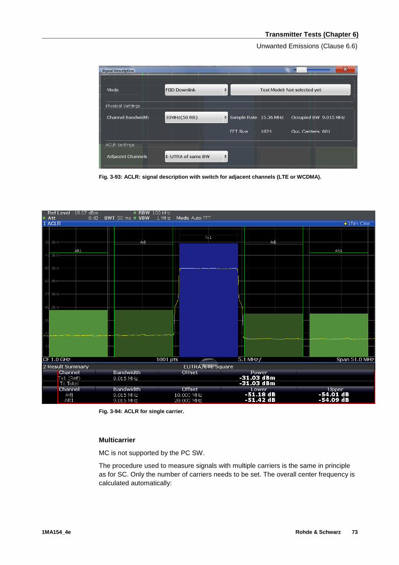
Fig. 3-93: ACLR: signal description with switch for adjacent channels (LTE or WCDMA).
Fig. 3-94: ACLR for single carrier.
Multicarrier
MC is not supported by the PC SW.
The procedure used to measure signals with multiple carriers is the same in principle
as for SC. Only the number of carriers needs to be set. The overall center frequency is
calculated automatically:

Transmitter Tests (Chapter 6)
Unwanted Emissions (Clause 6.6)
1MA154_4e Rohde & Schwarz 74
ı Odd number of Tx channels: The middle Tx channel is centered to center
frequency.
ı Even number of Tx channels: The two Tx channels in the middle are used to
calculate the frequency between those two channels. This frequency is aligned to
the center frequency.
The procedure is illustrated here using the multicarriers example from chapter 2.2 (see
Fig. 2-3):
Fig. 3-95: Setting the 4 carrier bandwidths, 1.095 MHz + 3 times 4.515 MHz.
Fig. 3-96: Setting the 4 carrier spacings, 1.4 MHz + 3 times 5 MHz.

Transmitter Tests (Chapter 6)
Unwanted Emissions (Clause 6.6)
1MA154_4e Rohde & Schwarz 75
Fig. 3-97: ACLR with multicarriers.
Note that in this case, two measurements must be taken because the outer carriers
have different bandwidths (1.4 MHz and 5 MHz in the example) and therefore the
adjacent channels to be measured also have different bandwidths per Table 3-16 and
Table 3-17. These must be set under Adjacent channels (Fig. 3-95 and Fig. 3-96).
Demo program
This test requires additional settings. The BS category affects the limit settings. The
adjacent channel to be measured must also be specified. Noise Cancellation is
enabled by default.
Fig. 3-98: Special settings for ACLR.
The measured power values for the individual channels are output together with a
global limit check. MC tests are not supported by the PC SW.

Transmitter Tests (Chapter 6)
Unwanted Emissions (Clause 6.6)
1MA154_4e Rohde & Schwarz 76
Fig. 3-99: Example report for test case 6.6.2 with a two-carrier MC configuration.
3.6.3 Operating Band Unwanted Emissions (SEM) (Clause 6.6.3)
The operating band unwanted emission limits are defined from 10 MHz below the
lowest frequency of the downlink operating band up to 10 MHz above the highest
frequency of the downlink operating band.
In multicarrier or intra-band contiguous carrier aggregation, the test measurement is
applicable below the lower edge of the lowest carrier and above the higher edge of the
highest carrier in the aggregated channel bandwidth present in an operating band.
The test requirements shall apply as per categories either A or B. The minimum
mandatory requirement is mentioned in subclause 6.6.3.5.1 or subclause 6.6.3.5.2 [1],
whichever is applicable to the different type of base stations. There are other optional
requirements applicable regionally in subclause 6.6.3.5[2-3] [1].
Test setup
Fig. 3-100: Test setup for BS output power.
The DUT (base station) transmits with the declared maximum PRAT. E-TM1.1 and E-
TM1.2 are required.

Transmitter Tests (Chapter 6)
Unwanted Emissions (Clause 6.6)
1MA154_4e Rohde & Schwarz 77
For TDD signals, the trigger must be set to external.MC is not supported at this time. It
will follow later in the internal FSW.
Procedure
The test is implemented in the LTE as a spectrum emission mask (SEM).
1. Under MEAS, select "Spectrum Emission Mask" in LTE.
2. The parameters defined under Signal Description (see Fig. 3-101) cause the
correct settings for the SEM test to be entered automatically. The BS category is
also important in that it determines the limits.
Fig. 3-101: SEM: selecting the predefined settings in LTE.
Fig. 3-102 shows a SEM test. The Result Summary displays the results of the
individual ranges. The global limit check is displayed along the top.
Fig. 3-102: Operating band unwanted emission (SEM).
Demo program

Transmitter Tests (Chapter 6)
Unwanted Emissions (Clause 6.6)
1MA154_4e Rohde & Schwarz 78
No further special settings are needed for this test. The test is carried out as a
spectrum measurement. The measured power values for the individual ranges are
output together with a global limit check. MC tests are not yet supported.
Fig. 3-103: Example report for test case 6.6.3.
3.6.4 Transmitter Spurious Emissions (Clause 6.6.4)
Spurious emissions are emissions which are caused by unwanted transmitter effects
such as harmonics emission, parasitic emission, intermodulation products and
frequency conversion products, but exclude out-of-band emissions [1].
Fig. 3-104: Spurious emissions.
The transmitter spurious emission limits apply from 9 kHz to 12.75 GHz, excluding the
frequency range from 10 MHz below the lowest frequency of the downlink operating
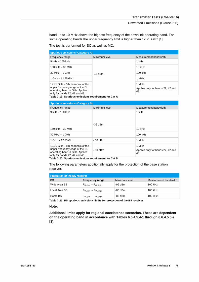
Transmitter Tests (Chapter 6)
Unwanted Emissions (Clause 6.6)
1MA154_4e Rohde & Schwarz 79
band up to 10 MHz above the highest frequency of the downlink operating band. For
some operating bands the upper frequency limit is higher than 12.75 GHz [1].
The test is performed for SC as well as MC.
Spurious emissions (Category A)
Frequency range Maximum level Measurement bandwidth
9 kHz – 150 kHz
-13 dBm
1 kHz
150 kHz – 30 MHz 10 kHz
30 MHz – 1 GHz 100 kHz
1 GHz – 12.75 GHz 1 MHz
12.75 GHz – 5th harmonic of the upper frequency edge of the DL operating band in GHz. Applies only for bands 22, 42 and 43.
1 MHz
Applies only for bands 22, 42 and 43.
Table 3-19: Spurious emissions requirement for Cat A
Spurious emissions (Category B)
Frequency range Maximum level Measurement bandwidth
9 kHz – 150 kHz
-36 dBm
1 kHz
150 kHz – 30 MHz 10 kHz
30 MHz – 1 GHz 100 kHz
1 GHz – 12.75 GHz - 30 dBm 1 MHz
12.75 GHz – 5th harmonic of the upper frequency edge of the DL operating band in GHz. Applies only for bands 22, 42 and 43.
- 30 dBm
1 MHz
Applies only for bands 22, 42 and 43.
Table 3-20: Spurious emissions requirement for Cat B
The following parameters additionally apply for the protection of the base station
receiver:
Protection of the BS receiver
BS Frequency range Maximum level Measurement bandwidth
Wide Area BS FUL_low – FUL_high -96 dBm 100 kHz
Local Area BS FUL_low – FUL_high -88 dBm 100 kHz
Home BS FUL_low – FUL_high -88 dBm 100 kHz
Table 3-21: BS spurious emissions limits for protection of the BS receiver
Note:
Additional limits apply for regional coexistence scenarios. These are dependent
on the operating band in accordance with Tables 6.6.4.5.4-1 through 6.6.4.5.5-2
[1].

Transmitter Tests (Chapter 6)
Unwanted Emissions (Clause 6.6)
1MA154_4e Rohde & Schwarz 80
Test setup
The test requires a notch (or a diplexer) filter that suppresses the frequency range of
the LTE carrier on the base station. This makes it possible to meet high dynamic
requirements (e.g. DUT transmits with 24 dBm, Limit in Protection receiver test –96
dBm -> dynamic is 120 dB).
Fig. 3-105: Test setup: spurious emissions.
The DUT (base station) transmits with the declared maximum PRAT. E-TM1.1 is
required.
Procedure
1. In spectrum mode, select MEAS and then "Spurious Emissions".
2. Under Sweep List check the settings and adapt them as necessary. The
predefined level values apply for Category A.
3. Press Adjust X-Axis. The settings are prefilled.
Fig. 3-106: Spurious emissions: predefined sweep list.

Transmitter Tests (Chapter 6)
Unwanted Emissions (Clause 6.6)
1MA154_4e Rohde & Schwarz 81
Fig. 3-107: Spurious emissions up to 12.75 GHz. The carrier is suppressed using filters. The results
for the individual ranges are displayed at the bottom, and at the top is the limit check.
Demo program
This test requires additional settings. The BS category affects the limit settings. The
test is performed in the base unit as a spectrum measurement, which means that it
cannot be performed directly using the PC SW. The measured ranges and a limit
check are reported.
Fig. 3-108: Special settings for spurious emissions.
Fig. 3-109: Example report for test case 6.6.4.

Transmitter Tests (Chapter 6)
Transmitter Intermodulation (Clause 6.7)
1MA154_4e Rohde & Schwarz 82
3.7 Transmitter Intermodulation (Clause 6.7)
The transmit intermodulation requirement is a measure of the capability of the
transmitter to inhibit the generation of signals in its nonlinear elements caused by
presence of the own transmit signal and an interfering signal reaching the transmitter
via the antenna. The requirement applies during the transmitter ON period and the
transmitter transient period.
The transmit intermodulation level is the power of the intermodulation products when
an E-UTRA signal of channel bandwidth 5 MHz as an interfering signal is injected into
an antenna connector at a mean power level of 30 dB lower than that of the mean
power of the wanted signal. [1]
The test is performed for SC as well as MC.
Fig. 3-110: Transmit intermodulation.
Transmit intermodulation
Wanted signal Interfering signal Parameter Frequency offset
LTE signal with maximum bandwidth with E-TM1.1
5 MHz LTE signal with
E-TM1.1
- 30 dBc
Interfering signal center frequency offset from the lower ( higher ) edge of the wanted signal
±2.5 MHz
±7.5 MHz
±12.5 MHz
Table 3-22: Transmit intermodulation parameters

Transmitter Tests (Chapter 6)
Transmitter Intermodulation (Clause 6.7)
1MA154_4e Rohde & Schwarz 83
Test setup
Fig. 3-111: Test setup: transmitter intermodulation.
Overview of settings:
ı The DUT (base station) generates the wanted signal at FC with BWChannel and E-
TM1.1.
ı The SMx generates a 5 MHz LTE signal with E-TM1.1 and the offsets in
accordance with Table 3-22
Procedure
Use the SMx to generate a 5 MHz LTE signal with E-TM1.1 as described in Section
3.1.2. The frequency offset is entered directly under Frequency as described in Table
3-22. Set the level so that it is 30 dB under the level of the wanted signal.
The measurements shall be limited to the frequency ranges of all third and fifth order
intermodulation products, excluding the channel bandwidths of the wanted and
interfering signals.
The measurement regions are then calculated according to the table:
Measurement regions calculation
Order of intermodulation products Center frequency Intermodulation width
3rd order
2F1 ± F2 2*BWChannel + 1*5 MHz
2F2 ± F1 2*5 MHz + 1*BWChannel
5th order
3F1 ± 2F2 3*BWChannel + 2*5 MHz
3F2 ± 2F1 3*5 MHz + 2*BWChannel
4F1 ± F2 4*BWChannel + 1*5 MHz
4F2 ± F1 4*5 MHz + 1*BWChannel
Note: F1: Wanted signal, F2: Interferer
Table 3-23: Calculating the measurement regions for the intermodulation product
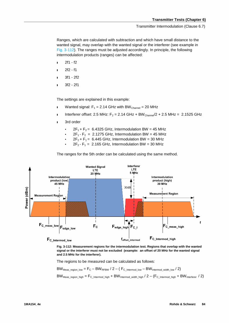
Transmitter Tests (Chapter 6)
Transmitter Intermodulation (Clause 6.7)
1MA154_4e Rohde & Schwarz 84
Ranges, which are calculated with subtraction and which have small distance to the
wanted signal, may overlap with the wanted signal or the interferer (see example in
Fig. 3-112). The ranges must be adjusted accordingly. In principle, the following
intermodulation products (ranges) can be affected:
ı 2f1 - f2
ı 2f2 - f1
ı 3f1 - 2f2
ı 3f2 - 2f1
The settings are explained in this example:
ı Wanted signal: F1 = 2.14 GHz with BWChannel = 20 MHz
ı Interferer offset: 2.5 MHz: F2 = 2.14 GHz + BWChannel/2 + 2.5 MHz = 2.1525 GHz
ı 3rd order
▪ 2F1 + F2 = 6.4325 GHz, Intermodulation BW = 45 MHz
▪ 2F1 - F2 = 2.1275 GHz, Intermodulation BW = 45 MHz
▪ 2F2 + F1 = 6.445 GHz, Intermodulation BW = 30 MHz
▪ 2F2 - F1 = 2.165 GHz, Intermodulation BW = 30 MHz
The ranges for the 5th order can be calculated using the same method.
Fig. 3-112: Measurement regions for the intermodulation test. Regions that overlap with the wanted
signal or the interferer must not be excluded (example: an offset of 20 MHz for the wanted signal
and 2.5 MHz for the interferer).
The regions to be measured can be calculated as follows:
BWMeas_region_low = FC – BWRFBW / 2 – ( FC_Intermod_low – BWIntermod_width_low / 2)
BWMeas_region_high = FC_Intermod_high + BWIntermod_width_high / 2 – (FC_Intermod_high + BWInterferer / 2)

Transmitter Tests (Chapter 6)
Transmitter Intermodulation (Clause 6.7)
1MA154_4e Rohde & Schwarz 85
The following regions result for the example:
BWMeas_region_low = 2140 MHz – 2127.5 MHz – 20 MHz / 2 + 45 MHz / 2 = 25 MHz
BWMeas_region_high = 2165 MHz – 2140 MHz – 20 MHz / 2 – 5 MHz + 30 MHz / 2 = 25
MHz
Measurements
The same conditions apply for these measurements as for:
ı ACLR
ı Operating band unwanted emissions (SEM)
ı Spurious emissions
The measurement regions can be limited to the regions containing the intermodulation
products.
ACLR
The procedure for the ACLR measurement is the same as described for ACLR in
Section 3.6.2, except that the measurement regions must be adapted:
1. Start the ACLR test
2. Set the bandwidth for TX1 (example: 18 MHz) and for the ADJ channel on the
intermodulation bandwidth (e.g. 25 MHz)
Fig. 3-113: Transmit intermodulation: Setting the bandwidths (18 MHz for the wanted signal and
25 MHz for the intermodulation bandwidth in the example).
3. Set the offset of the left intermodulation product (e.g. FC – FC_meas_low = 22.5 MHz).

Transmitter Tests (Chapter 6)
Transmitter Intermodulation (Clause 6.7)
1MA154_4e Rohde & Schwarz 86
Fig. 3-114: Transmit intermodulation: set the intermodulation product spacing (FC – FC_meas_low =
22.5 MHz in the example).
5 MHz BW
Interferer
20 MHz BW
Wanted Signal
Measurement Region,
25 MHz
FC_meas_low
Fig. 3-115: Transmit intermodulation: measuring the left intermodulation product.
4. Set the spacing of the right intermodulation product (example: FC_meas_high – FC =
BWMeas_region_low / 2 + BWChannel / 2 + BW Interferer = 27.5 MHz).

Transmitter Tests (Chapter 6)
Transmitter Intermodulation (Clause 6.7)
1MA154_4e Rohde & Schwarz 87
5MHz BW
Interferer
FC_meas_high
Measurement Region,
25MHz
20MHz BW
Wanted Signal
Fig. 3-116: Transmit intermodulation: Measuring the right intermodulation product. The interferer is
excluded from the test.
5. Repeat the procedure for the other tests (3rd + 5th order, each with different
offsets)
Operating band unwanted emission (SEM)
The procedure for the SEM measurement is the same as described for SEM in Section
3.6.3, except that the measurement regions must be adjusted:
1. Adjust the measurement region to the intermodulation products. This is done via
SPAN (example: intermodulation regions to be measured = 25 MHz on both sides,
SPAN = 2 * 25 MHz + 20 MHz (BWwanted signal) = 70 MHz)
2. Adjust the SWEEP times for the modified regions in the SWEEP LIST, e.g. by
setting to AUTO (Fig. 3-117).

Transmitter Tests (Chapter 6)
Transmitter Intermodulation (Clause 6.7)
1MA154_4e Rohde & Schwarz 88
Fig. 3-117: Setting the sweep time.
20 MHz BW
Wanted Signal 5 MHz BW
Interferer
Measurement Region,
25 MHz
Measurement Region,
25 MHz
Fig. 3-118: Transmit intermodulation: adjusted SEM test.
Spurious emissions
The procedure for the spurious emissions test is the same as described for Spurious
Emissions in Section 3.6.4.
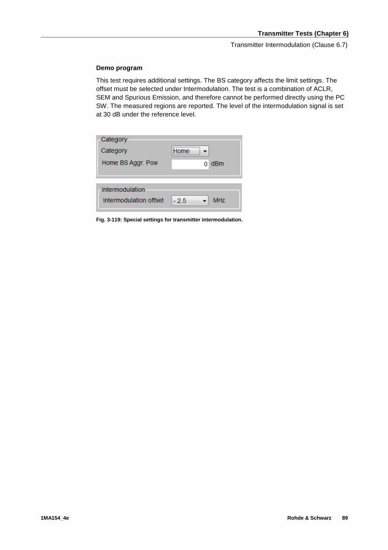
Transmitter Tests (Chapter 6)
Transmitter Intermodulation (Clause 6.7)
1MA154_4e Rohde & Schwarz 89
Demo program
This test requires additional settings. The BS category affects the limit settings. The
offset must be selected under Intermodulation. The test is a combination of ACLR,
SEM and Spurious Emission, and therefore cannot be performed directly using the PC
SW. The measured regions are reported. The level of the intermodulation signal is set
at 30 dB under the reference level.
Fig. 3-119: Special settings for transmitter intermodulation.

Transmitter Tests (Chapter 6)
Transmitter Intermodulation (Clause 6.7)
1MA154_4e Rohde & Schwarz 90
Fig. 3-120: Example report for test case 6.7. The measurement is taken on the intermodulation
products.
Appendix
1MA154_4e Rohde & Schwarz 91
4 Appendix
4.1 R&S TSrun Program
The TSrun software application makes it possible to combine tests (modules) provided
by Rohde & Schwarz into test plans to allow rapid and easy remote control of test
instruments. This program is available free of charge from our website.
Requirements
Operating system:
ı Microsoft Windows XP / Vista / Windows 7 / Windows 8
ı .NET framework V4.0 or higher
General PC requirements:
ı Pentium 1 GHz or faster
ı 1 Gbyte RAM
ı 100 Mbyte space harddisk
ı XGA monitor (1024x768)
Remote control interface:
ı National Instruments VISA
ı GPIB card
Or
ı LAN connectionAfter TSrun is launched, the following splash screen appears:

Appendix
1MA154_4e Rohde & Schwarz 92
Fig. 4-1: Overview TSrun
Tests and test plans
Tests are separate, closed modules for TSrun. A test plan can consist of one or more
tests.

Appendix
1MA154_4e Rohde & Schwarz 93
Fig. 4-2: Overview of a test plan in TSrun. The test plan in the example contains only one test
(LTE_BS_Tx_Tests). After the test is completed, the bar along the bottom can be used to display the
measurement and SCPI reports.
The LTE BS tests can be found under Tests/ApplicationNotes.
Click RUN to start the current test plan.
SCPI connections
Under Resources|SCPI Connections you can add all required instruments for remote
control.

Appendix
1MA154_4e Rohde & Schwarz 94
Fig. 4-3: Setting the SCPI connections.
Use Configure… to open a wizard for entering the VISA parameters (Fig. 4-5). Enter
"localhost" for the external PC SW. Use the Test Connection button to test the
connection to the instrument. When the Demo Mode button is enabled, no instruments
need to be connected because TSrun will run in demo mode and output a fictitious test
report.
Fig. 4-4: SCPI connections.

Appendix
1MA154_4e Rohde & Schwarz 95
Fig. 4-5: Wizard for entering VISA parameters. Both the IP address and a host name can be entered
directly.
Reports: Measurement and SCPI
After the test is completed, TSrun automatically generates both a measurement and a
SCPI report.
The measurement report shows the actual results and the selected settings.
The SCPI report returns a LOG file of all transmitted SCPI commands. These can then
be copied and easily used in separate applications.

Appendix
1MA154_4e Rohde & Schwarz 96
Fig. 4-6: SCPI report.
4.2 References
[1] Technical Specification Group Radio Access Network; E-UTRA Base station
conformance testing , Release 10; 3GPP TS 36.141, V 10.12.0, September 2013
[2] Rohde & Schwarz: UMTS Long Term Evolution (LTE) Technology Introduction,
Application Note 1MA111, October 2012
[3] Rohde & Schwarz: LTE-A Base Station Receiver Tests according to TS 36.141
Rel. 10, Application Note 1MA195, October 2013
[4] Rohde & Schwarz: LTE-A Base Station Performance Tests according to TS
36.141 Rel. 10, Application Note 1MA162, October 2013
[5] Technical Specification Group Radio Access Network; E-UTRA, UTRA and
GSM/EDGE; Multistandard Radio (MSR) Base Station (BS) conformance testing,
Release 10; 3GPP TS 37.141, V 10.10.0, July 2013
[6] Rohde & Schwarz: Measuring Multistandard Radio Base Stations according to
TS 37.141, Application Note 1MA198, July 2012

Appendix
1MA154_4e Rohde & Schwarz 97
4.3 Additional Information
Please send your comments and suggestions regarding this white paper to
4.4 Ordering Information
Ordering information for signal generators
Vector signal generator
Product description Type Ordering No.
Vector Signal Generator SMU200A 1141.2005.02
Baseband Generator SMU-B9 1161.0766.02
Baseband Generator SMU-B10 1141.7007.02
SMU-B11 Baseband Generator SMU-B11 1159.8411.02
Baseband Main Module SMU-B13 1141.8003.04
1st RF path SMU-B10x
2nd RF path SMU-B20x
AWGN SMU-K62 1159.8511.02
Digital Standard LTE/E-UTRA SMU-K55 1408.7310.02
LTE Release 10 / LTE-Advanced SMU-K85 1408.8498.02
3GPP FDD SMU-K42
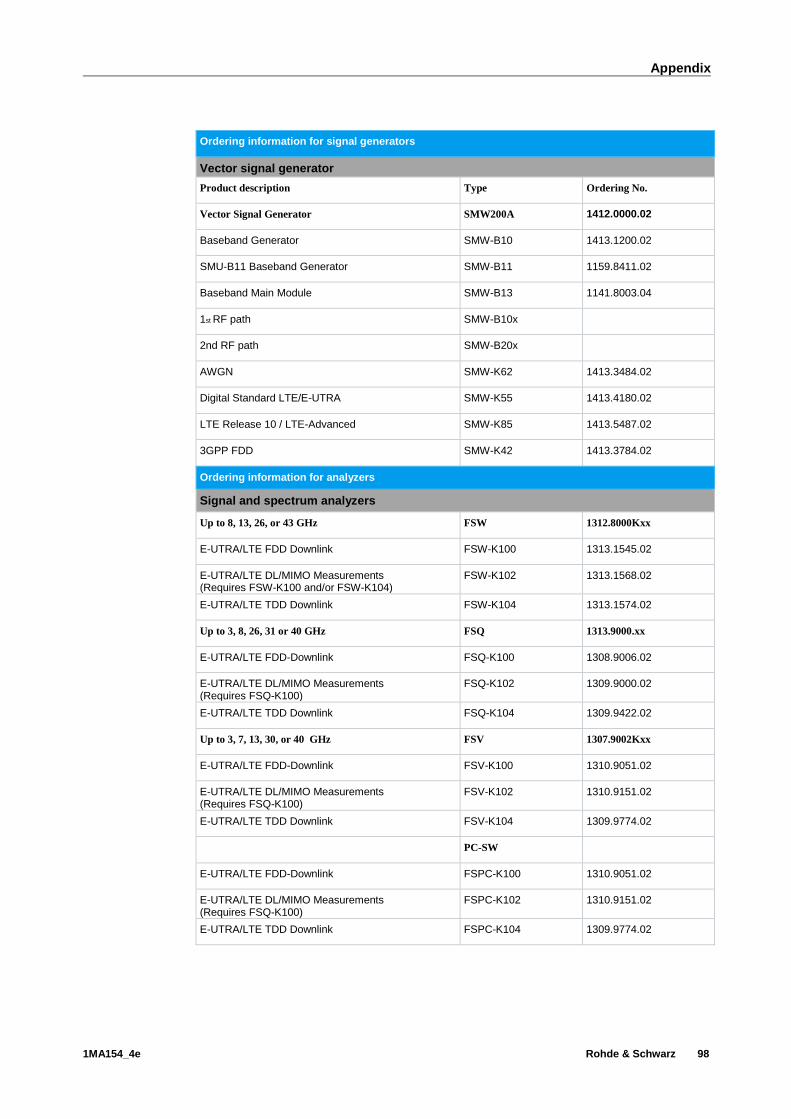
Appendix
1MA154_4e Rohde & Schwarz 98
Ordering information for signal generators
Vector signal generator
Product description Type Ordering No.
Vector Signal Generator SMW200A 1412.0000.02
Baseband Generator SMW-B10 1413.1200.02
SMU-B11 Baseband Generator SMW-B11 1159.8411.02
Baseband Main Module SMW-B13 1141.8003.04
1st RF path SMW-B10x
2nd RF path SMW-B20x
AWGN SMW-K62 1413.3484.02
Digital Standard LTE/E-UTRA SMW-K55 1413.4180.02
LTE Release 10 / LTE-Advanced SMW-K85 1413.5487.02
3GPP FDD SMW-K42 1413.3784.02
Ordering information for analyzers
Signal and spectrum analyzers
Up to 8, 13, 26, or 43 GHz FSW 1312.8000Kxx
E-UTRA/LTE FDD Downlink FSW-K100 1313.1545.02
E-UTRA/LTE DL/MIMO Measurements (Requires FSW-K100 and/or FSW-K104)
FSW-K102 1313.1568.02
E-UTRA/LTE TDD Downlink FSW-K104 1313.1574.02
Up to 3, 8, 26, 31 or 40 GHz FSQ 1313.9000.xx
E-UTRA/LTE FDD-Downlink FSQ-K100 1308.9006.02
E-UTRA/LTE DL/MIMO Measurements (Requires FSQ-K100)
FSQ-K102 1309.9000.02
E-UTRA/LTE TDD Downlink FSQ-K104 1309.9422.02
Up to 3, 7, 13, 30, or 40 GHz FSV 1307.9002Kxx
E-UTRA/LTE FDD-Downlink FSV-K100 1310.9051.02
E-UTRA/LTE DL/MIMO Measurements (Requires FSQ-K100)
FSV-K102 1310.9151.02
E-UTRA/LTE TDD Downlink FSV-K104 1309.9774.02
PC-SW
E-UTRA/LTE FDD-Downlink FSPC-K100 1310.9051.02
E-UTRA/LTE DL/MIMO Measurements (Requires FSQ-K100)
FSPC-K102 1310.9151.02
E-UTRA/LTE TDD Downlink FSPC-K104 1309.9774.02

Appendix
1MA154_4e Rohde & Schwarz 99

About Rohde & Schwarz
Rohde & Schwarz is an independent group of
companies specializing in electronics. It is a leading
supplier of solutions in the fields of test and
measurement, broadcasting, radiomonitoring and
radiolocation, as well as secure communications.
Established more than 75 years ago, Rohde &
Schwarz has a global presence and a dedicated
service network in over 70 countries. Company
headquarters are in Munich, Germany.
Regional contact
Europe, Africa, Middle East +49 89 4129 12345 [email protected] North America 1-888-TEST-RSA (1-888-837-8772) [email protected] Latin America +1-410-910-7988 [email protected] Asia/Pacific +65 65 13 04 88 [email protected]
China +86-800-810-8228 /+86-400-650-5896 [email protected]
Environmental commitment
ı Energy-efficient products
ı Continuous improvement in environmental
sustainability
ı ISO 14001-certified environmental
management system
This application note and the supplied programs
may only be used subject to the conditions of use
set forth in the download area of the Rohde &
Schwarz website.
R&S® is a registered trademark of Rohde & Schwarz GmbH & Co.
KG; Trade names are trademarks of the owners.


![LTE-A Base Station Receiver Tests - Rohde & Schwarz...The LTE-A conformance tests for base stations (eNodeB) are defined in 3GPP TS 36.141 Release 14 [1] and include transmitter (Tx),](https://img.dokumen.tips/doc/110x75/5f0bf4fb7e708231d4330dac/lte-a-base-station-receiver-tests-rohde-schwarz-the-lte-a-conformance.jpg)


![An LTE Transmitter Using a Class-A/B Power Mixer[1]](https://img.dokumen.tips/doc/110x75/5681637c550346895dd45a75/an-lte-transmitter-using-a-class-ab-power-mixer1.jpg)