Embed Size (px)
Citation preview

NCHRP 24-31
LRFD DESIGN SPECIFICATIONS FOR SHALLOW FOUNDATIONS
Final Report September 2009
APPENDIX H
DESIGN EXAMPLES
Prepared for National Cooperative Highway Research Program
Transportation Research Board National Research Council
Shailendra Amatya Geotechnical Engineering Research Laboratory, University of Massachusetts Lowell,
1 University Avenue, Lowell, MA 01854
Samuel G. Paikowsky Geosciences Testing and Research, Inc., 55 Middlesex Street, Ste. 225,
North Chelmsford, MA 01863 and
Geotechnical Engineering Research Laboratory, University of Massachusetts Lowell, 1 University Avenue, Lowell, MA 01854
Kerstin Lesny
Institute of Soil Mechanics and Foundation Engineering Department of Civil Engineering, University of Duisburg-Essen, Germany
LIMITED USE DOCUMENT
This Appendix is furnished only for review by members of the NCHRP project panel and is regarded as fully privileged. Dissemination of information included herein must be approved by the NCHRP and Geosciences Testing and Research, Inc.


H-i
TABLE OF CONTENTS H.1. EXAMPLE 1: BRIDGE PIER ON NATURAL SOIL DEPOSITS – GEC6-
EXAMPLE 1 ............................................................................................................... H-1 H.1.1. Subsurface Condition H.1.2. Loads, Load Combinations and Limit States H.1.3. Soil Parameter Estimation H.1.4. Nominal Bearing Resistances at the Limit State
H.1.4.1. Footing Information: Embedment and Shape H.1.4.2. Bearing Capacity Factors H.1.4.3. Bearing Capacity Modification Factors H.1.4.4. Modified Bearing Capacity Factors H.1.4.5. Groundwater Table Modification Factors H.1.4.6. Bearing Capacity
H.1.5. Allowable Bearing Resistance at the Limit State H.1.5.1. Overview H.1.5.2. AASHTO (2007) Method H.1.5.3. Schmertmann et al. (1978) Method H.1.5.4. Hough (1959) Method
H.1.6. Resistance Factors H.1.7. Design Footing Width H.1.8. Sliding Resistance H.1.9. Discussions and Conclusions
H.2. EXAMPLE 2: BILLERICA BRIDGE, CENTRAL PIER ON GRAVEL FILL ......... H-22 H.2.1. General Information H.2.2. Subsurface Conditions H.2.3. Loads, Load Combinations and Limit States H.2.4. Nominal Bearing Resistances at the Limit State
H.2.4.1. Footing Information H.2.4.2. Bearing Capacity Factors H.2.4.3. Bearing Capacity Modification Factors H.2.4.4. Modified Bearing Capacity Factors for Strength-I C7 LS H.2.4.5. Groundwater Table Modification Factors H.2.4.6. Bearing Capacity for Strength-I C7 LS
H.2.5. Allowable Bearing Resistances at the Limit States H.2.5.1. Overview H.2.5.2. AASHTO (2007) Method H.2.5.3. Schmertmann et al. (1978) Method H.2.5.4. Hough (1959) Method
H.2.6. Resistance Factors H.2.7. Design Footing Width H.2.8. Sliding Resistance H.2.9. Discussions and Conclusions
H.3. EXAMPLE 3: BILLERICA BRIDGE, EAST ABUTMENT ON GRAVEL FILL .... H-39 H.3.1. Subsurface Conditions H.3.2. Loads, Load Combinations and Limit States

H-ii
H.3.3. Nominal Bearing Resistances at the Limit States H.3.4. Design Footing Width H.3.5. Sliding Resistance H.3.6. Discussions and Conclusions
H.4. EXAMPLE 4: INTEGRAL BRIDGE ABUTMENT ON STRUCTURAL FILL – GEC6–EXAMPLE 2 ................................................................................................. H-47 H.4.1. Subsurface Conditions H.4.2. Loads, Load Combinations and Limit States H.4.3. Nominal Bearing Resistances at the Limit States H.4.4. Design Footing Width H.4.5. Sliding Resistance H.4.6. Discussions and Conclusions
H.5. EXAMPLE 5: STUB SEAT-TYPE BRIDGE ABUTMENT ON STRUCTURAL FILL – GEC6-EXAMPLE 3 ...................................................................................... H-55 H.5.1. Subsurface Conditions H.5.2. Loads, Load Combinations and Limit States H.5.3. Nominal Bearing Resistances at the Limit States H.5.4. Design Footing Width H.5.5. Sliding Resistance H.5.6. Discussions and Conclusions
H.6. EXAMPLE 6: FULL HEIGHT BRIDGE ABUTMENT ON NATURAL SOIL − GEC6-EXAMPLE 4 .................................................................................................. H-64 H.6.1. Subsurface Conditions H.6.2. Loads, Load Combinations and Limit States H.6.3. Nominal Bearing Resistances at the Limit States H.6.4. Design Footing Width H.6.5. Sliding Resistance H.6.6. Discussions and Conclusions
H.7. EXAMPLE 7: NEW MARLBOROUGH BRIDGE, SOUTH ABUTMENT ON ROCK ....................................................................................................................... H-72 H.7.1. General Information H.7.2. Subsurface Conditions H.7.3. Loads, Load Combinations and Limit States H.7.4. Estimation of Rock Parameters H.7.5. Nominal and Allowable Bearing Resistances at the Limit States H.7.6. Design Footing Width H.7.7. Sliding Resistance H.7.8. Discussions and Conclusions

H-1
H.1 EXAMPLE 1: BRIDGE PIER ON NATURAL SOIL DEPOSITS – GEC6-EXAMPLE 1
H.1.1 Subsurface Condition
The subsurface conditions given in Example C1 of FHWA Geotechnical Engineering Circular No. 6 (GEC6), Appendix C (Kimmerling, 2002) are summarized in Table H-1. The groundwater table is at a depth of 30.0ft below the ground surface and the soil unit weight is assumed to be 125pcf for all the layers. The soil friction angles are calculated using the correlation with SPT blow counts proposed by Peck, Hanson and Thornburn (PHT) as modified by Kulhawy and Mayne (1990). This calculation is compatible with the methodology used in developing the resistance factors. The footing is to be cast in-situ on the silty sand layer.
TABLE H-1. Soil parameters – Example 1 (GEC6-Example 1)
Depth (ft) SPT Layer # Depth (ft) Soil Description γ (pcf) φf (deg)
2.5 6 1 7.55 Lean Clay 124.9 not needed 5.0 7 2 14.4 Silty Sand 124.9 34.5 7.5 18 3a 30.0 Well-graded Sand above GW 124.9 37.5
10.1 20 3b 39.7 Well-graded Sand below GW 62.4 36.0 12.6 22 4 49.5 Clean, uniform Sand 62.4 35.0 15.1 42 20.0 38 * Groundwater table present at a depth of 30.0ft 24.9 47 29.9 33 34.8 45 39.7 49 44.6 42 49.5 37
H.1.2 Loads, Load Combinations and Limit States
The loading from the structure at the footing base is presented in Table H-2. The notations for the loadings and the sign conventions used in the calculation follow Figure 120 of Chapter 5, hence the moments My and Mz in Figure H-1 correspond to M3 and M2, respectively, and vertical load P to F1. F2 is the horizontal loading along the transverse direction of the bridge (along y-axis). It should be noted that all load components are one-way inclined (across the bridge) and two-way eccentric. In addition to the loadings given in Table H-2, the weight of the footing and the soil above the footing have been considered as a vertical-centric load of 519.2 kips (1154.02 kN).
Table H-3 includes the investigated load combinations and the resultant characteristic loading as well as the resultant load inclination F2/F1 and the eccentricity in both directions; e2 = eL and e3 = eB for the different load combinations. Here, M2 = Mz and M3 = My and for the square footing B = L (see Figure 120 of Chapter 5 and Figure H-1). Table H-4 summarizes the load factors for the strength limit state applied to the bearing capacity calculations (Table H-4.1) and the sliding calculations (Table H-4.2).

H-2
Figure H-1. Geometry of interior bridge pier founded on spread footing – example 1 (GEC6-Example 1)
TABLE H-2. Load at the column base of the bridge pier
Load at Column Base F1 kips (kN)
F2 kips (kN)
M2 kip-ft (kNm)
M3 kip-ft (kNm)
dead load (DL) 1438.7 (6400.0) 37.5 (167.0) 155.6 (211.0) 551.5 (748.0) live load (LL) 375.4 (1670.0) 9.4 (42.0) 301.6 (409.0) 144.9 (196.5) impact (IM) (neglected) 70.8 (315.0) 1.8 (8.0) 56.8 (77.0) 27.3 (37.0) wind on structure (WS) 198.7 (884.0) 11.0 (49.0) 65.6 (89.0) 166.6 (226.0) wind on live load (WL) 4.0 (18.0) 0.9 (4.0) 5.2 (7.0) 19.2 (26.0) earthquake (EQ) 375.6 (1671.0) 180.7 (804.0) 1235.1 (1675.0) 4089.3 (5546.0)
TABLE H-3. Load combinations and resultant characteristic (unfactored) loading
Load Combinations
F1 kips (kN)
F2 kips (kN)
M2 kips-ft (kNm)
M3 kips-ft (kNm)
F2/F1 eL = M3/F1
ft (m)
eB = M2/F1 ft
(m) Service-I: DL+LL+WS+WL
2137.2 (9507.2)
51.2 (227.7)
482.0 (653.7)
765.6 (1038.3) 0.024 0.358
(0.109) 0.226
(0.069)
Strength-I: DL+LL 2073.6 (9224.0)
47.0 (209.0)
457.2 (620.0)
696.4 (944.5) 0.023 0.335
(0.102) 0.220
(0.067)
Extreme-I: DL+EQ 2073.8 (9225.0)
218.3 (971.0)
1390.6 (1886.0)
4640.8 (6294.0) 0.105 2.237
(0.682) 0.669
(0.204)

H-3
TABLE H-4.1 Load factors used for the bearing capacity strength limit state
Load Combination Limit State DL DW EH
LL, IM, CE, BR, PL, LS,
EL
WA WS WL FR EQ
Strength-I 1.25 1.5 1.5 1.75 1 0.0 0 1 0 Strength-II 1.25 1.5 1.5 1.35 1 0.0 0 1 0 Strength-III 1.25 1.5 1.5 0.00 1 1.4 0 1 0 Strength-IV 1.25 1.5 1.5 0.00 1 0.0 0 1 0 DC ONLY 1.50 1.5 1.5 Strength-V 1.25 1.5 1.5 1.35 1 0.4 1 1 0 Extreme Event-I 1.25 1.5 1.5 γEQ 1 0.0 0 1 1 Extreme Event-II 1.25 1.5 1.5 0.50 1 0.0 0 1 0 Service-I 1.00 1.0 1.0 1.00 1 0.3 1 1 0 Service-II 1.00 1.0 1.0 1.30 1 0.0 0 1 0 Service-III 1.00 1.0 1.0 0.80 1 0.0 0 1 0
γEQ shall be determined on project-specific basis γEQ =0 or 1 (0 in the example)
TABLE H-4.2 Load factors used for the sliding strength limit state
Load Combination Limit State DL DW EH
LL, IM, CE, BR, PL, LS,
EL
WA WS WL FR EQ
Strength-I 0.9 0.65 1.5 1.75 1 0.0 0 1 0 Strength-II 0.9 0.65 1.5 1.35 1 0.0 0 1 0 Strength-III 0.9 0.65 1.5 0.00 1 1.4 0 1 0 Strength-IV 0.9 0.65 1.5 0.00 1 0.0 0 1 0 DC ONLY 1.5 1.50 1.5 Strength-V 0.9 0.65 1.5 1.35 1 0.4 1 1 0 Extreme Event-I 0.9 0.65 1.5 γEQ 1 0.0 0 1 1 Extreme Event-II 0.9 0.65 1.5 0.50 1 0.0 0 1 0 Service-I 1.0 1.00 1.0 1.00 1 0.3 1 1 0 Service-II 1.0 1.00 1.0 1.30 1 0.0 0 1 0 Service-III 1.0 1.00 1.0 0.80 1 0.0 0 1 0
γEQ shall be determined on project-specific basis γEQ =0 or 1 (0 in the example) The calculation of the bearing resistance and the sliding resistance is based on the
characteristic load components (i.e., load eccentricity and inclination are obtained from unfactored load components) as given in Table H-3. However, for stability analysis, the design load components are required, which are summarized in Table H-5. The loads for Service-I are not factored (except for WS component), whereas, those for Strength-I and Extreme-I are factored by the load factors specified in Section 3 of the AASHTO (2007) specifications and provided in Tables H-4.1 and H-4.2. As the different limiting conditions make use of different factors (e.g. increased vertical loading for bearing capacity evaluation and decreased vertical loading for friction resistance in sliding evaluation), Table H-5 was divided to represent the
H-4
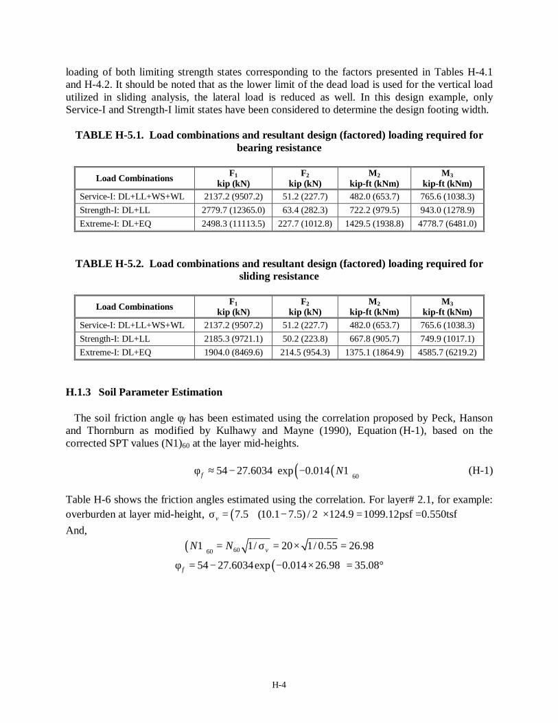
loading of both limiting strength states corresponding to the factors presented in Tables H-4.1 and H-4.2. It should be noted that as the lower limit of the dead load is used for the vertical load utilized in sliding analysis, the lateral load is reduced as well. In this design example, only Service-I and Strength-I limit states have been considered to determine the design footing width.
TABLE H-5.1. Load combinations and resultant design (factored) loading required for
bearing resistance
Load Combinations F1 kip (kN)
F2 kip (kN)
M2 kip-ft (kNm)
M3 kip-ft (kNm)
Service-I: DL+LL+WS+WL 2137.2 (9507.2) 51.2 (227.7) 482.0 (653.7) 765.6 (1038.3) Strength-I: DL+LL 2779.7 (12365.0) 63.4 (282.3) 722.2 (979.5) 943.0 (1278.9) Extreme-I: DL+EQ 2498.3 (11113.5) 227.7 (1012.8) 1429.5 (1938.8) 4778.7 (6481.0)
TABLE H-5.2. Load combinations and resultant design (factored) loading required for sliding resistance
Load Combinations F1
kip (kN) F2
kip (kN) M2
kip-ft (kNm) M3
kip-ft (kNm) Service-I: DL+LL+WS+WL 2137.2 (9507.2) 51.2 (227.7) 482.0 (653.7) 765.6 (1038.3) Strength-I: DL+LL 2185.3 (9721.1) 50.2 (223.8) 667.8 (905.7) 749.9 (1017.1) Extreme-I: DL+EQ 1904.0 (8469.6) 214.5 (954.3) 1375.1 (1864.9) 4585.7 (6219.2)
H.1.3 Soil Parameter Estimation
The soil friction angle φf has been estimated using the correlation proposed by Peck, Hanson and Thornburn as modified by Kulhawy and Mayne (1990), Equation (H-1), based on the corrected SPT values (N1)60 at the layer mid-heights.
( )( )6054 27.6034 exp 0.014 1f Nφ ≈ − ⋅ − (H-1)
Table H-6 shows the friction angles estimated using the correlation. For layer# 2.1, for example: overburden at layer mid-height, ( )7.5 (10.1 7.5) / 2 124.9 1099.12psf =0.550tsfvσ = + − × = And,
( )
( )6060
1 1/ 20 1/ 0.55 26.98
54 27.6034exp 0.014 26.98 35.08v
f
N N= σ = × =
φ = − − × = °

H-5
Table H-6. Estimation of soil friction angle from SPT N counts
Layer # Depth (ft) N60 Layer mid-height
overburden σv (tsf)
Corrected (N1)60 (Liao and
Whitmann 1986)
φf (deg) (PHT 1990)
1.1 2.5 6 0.079 21.37 lean clay 1.2 5.0 7 0.235 14.43
1.3 7.5 18 0.392 28.75 2.1 10.1 20 0.550 26.98 35.08 2.2 12.6 22 0.707 26.16 34.86 2.3 15.1 42 0.864 45.19 39.34 3a.1 20.0 38 1.095 36.31 37.40 3a.2 24.9 47 1.402 39.69 38.16 3a.3 29.9 33 1.709 25.24 34.61 3b.1 34.8 45 1.939 32.31 36.44 3b.2 39.7 49 2.093 33.87 36.82 4.1 44.6 42 2.246 28.02 35.35 4.2 49.5 37 2.400 23.88 34.24
The required soil parameters have been taken as the weighted average of the parameters of each layer to a depth of 2B + Df., considered as the influence depth from the ground level. E.g. For footing width of B = 4.9ft placed at an embedment depth of 7.5ft: The depth of influence for bearing capacity calculation is 2B + Df = 17.4ft. Hence,
64.365.74.17
37.40 15.1)-(17.4 39.34 12.6)-(15.1 34.86 10.1)-(12.6 35.08 7.5)-(10.1 average f =−
+++=φ
The average soil friction angle thus obtained hence varies according to the footing width. H.1.4 Nominal Bearing Resistances at the Limit State H.1.4.1 Footing Information: Embedment and Shape
The bearing resistances of square footings with widths 2.95ft to 20.70ft have been calculated. Since the soft lean clay is present at a shallow depth, underlain by stiffer sand layers, the footing has been considered to rest on the second soil layer, on silty sand, at an embedment depth of 7.55ft from the ground surface.
From Table H-3, the load eccentricities along the footing width and footing length are, respectively, eB = 0.220ft and eL = 0.335ft. Hence, for a trial footing width of, say, 4.9ft, the effective width B′ = B − 2eB = 4.9 − 2×0.220 = 4.48ft and the effective length L′ = L − 2eL = 4.9 − 2×0.335 = 4.25ft. H.1.4.2 Bearing Capacity Factors

H-6
The bearing resistances have been calculated for Strength-I limit state according to AASHTO (2007) (equation 10.6.3.1.2), Equations (95) through (99) in the draft Final Report, with depth modification factor as mentioned in Table 28.
For cohesionless soils, c = 0, hence the bearing capacity factors required are given by Equations (H-2) and (H-3).
( ) 2exp tan tan4 2
fq fN
φππ φ
= ⋅ +
(H-2)
( )2 1 tanq fN Nγ φ= + ⋅ (H-3)
For B = 4.9ft, the average φf has been obtained as 36.64°. Hence
Nq = exp{π tan(36.6)} tan2(45+36.6/2) = 41.00 , and Nγ = 2 (41.0+1) tan(36.6) = 62.46 H.1.4.3 Bearing Capacity Modification Factors Shape factors:
( )1 tan '/ ' 1 tan(36.6) (4.48 / 4.25) 1.784q fs B Lφ= + = + ⋅ = (H-4a) 1 0.4( '/ ') 1 0.4(4.48 / 4.25) 0.578s B Lγ = − = − = (H-4b)
Depth factors: For the current example, due to the presence of lean clay layer, the depth factor dq is taken as 1.0. Load inclination factors: The bearing capacity modification factors for load inclination are given by Equations (H-6).
( )
1' ' cot
n
qf
HiV A c φ
= − + ⋅ ⋅
(H-6a)
( )
1
1' ' cot
n
f
HiV A cγ φ
+ = − + ⋅ ⋅
(H-6b)
where H and V are the horizontal and vertical components of the applied inclined load P (unfactored), A′ is the effective area of footing, c′ is soil cohesion; and
( )( )
( )( )
2 22 / 2 /cos sin
1 / 1 /L B B L
nL B B L
θ θ ′ ′ ′ ′+ +
= + ′ ′ ′ ′+ + (H-6c)
where θ is the projected direction of load in the plane of the footing, measured from the side of length L in degrees; L′ and B ′ are effective length and width. Here the projected direction of the inclined load in the plane of the footing θ = 0°. Hence

H-7
2 4.25 / 4.48 1.5131 4.25 / 4.48
n += =
+
Then
1.51347.01 0.9659
2073.6 0qi = − = +
and
(1.513 1)47.01 0.9440
2073.6 0iγ
+ = − = +
H.1.4.4 Modified Bearing Capacity Factors
Nqm = Nqsqdqiq= 41.0×1.784×1.0×0.9659 = 70.64 and Nγm = Nγsγiγ = 62.46×0.578×0.9440 = 34.10 H.1.4.5 Groundwater Table Modification Factors
For B = 4.9ft, the groundwater table is below the depth of 1.5B from the footing base as well as the footing embedment Df;
1.5B+Df = 1.5×4.9 + 7.5 = 14.85ft < 29.9ft (GWT)
Therefore, the soil unit weights γ1 and γ2 are equal to γ. When 1.5B + Df > GWT, the soil unit weight below the footing base is taken as:
2 1 11.5w fw D D
B − γ
γ = γ × − − γ
H.1.4.6 Bearing Capacity
The nominal (unfactored) bearing resistance of the footing of width 4.9ft calculated using the bearing capacity equation given in AASHTO (2007) is thus
1 20.5
0 124.9 7.55 70.64 0.5 124.9 4.25 34.10 75.61ksfu cm f qm mq cN D N B Nγ′= + γ + γ
= + × × + × × × =
Table H-7 presents values of the average soil parameters, the bearing capacity factors and their modification factors and the calculated bearing capacity for footing widths 2.95ft to 20.67ft.

H-8
Table H-7. Detailed bearing capacity calculation for Example 1. Soil parameters and GWT:
124.929.9
Footing information:1.007.551.00 (taken as 1.0 because of lean clay layer present till the depth of Df from GL)1.00 (Vesic 1975)
Load eccentricity and inclination:0.023 (H along transverse dir.)0.3360.221
B (ft) B' L' 2B+Df avg φf Nq Nγ sq sγ pow n iq iγ Nqm Nγm 1.5B+Df γ1 γ2 qn (ksf) Qn (kips)2.95 2.51 2.28 13.5 35.6 35.90 52.84 1.788 0.560 1.524 0.9657 0.9438 62.00 27.90 12.0 124.9 124.9 62.40 357.43.94 3.50 3.27 15.4 36.5 40.01 60.59 1.791 0.572 1.517 0.9658 0.9439 69.20 32.70 13.5 124.9 124.9 71.88 820.44.92 4.48 4.25 17.4 36.6 40.99 62.46 1.784 0.578 1.513 0.9659 0.9440 70.64 34.10 14.9 124.9 124.9 75.61 1439.55.91 5.46 5.23 19.4 36.8 41.66 63.75 1.780 0.582 1.511 0.9660 0.9441 71.63 35.05 16.4 124.9 124.9 78.96 2258.06.89 6.45 6.22 21.3 36.9 42.54 65.46 1.780 0.585 1.509 0.9660 0.9441 73.14 36.16 17.9 124.9 124.9 82.96 3326.37.87 7.43 7.20 23.3 37.1 43.40 67.13 1.780 0.587 1.508 0.9660 0.9441 74.64 37.21 19.4 124.9 124.9 87.07 4660.88.86 8.42 8.19 25.3 37.1 43.71 67.72 1.779 0.589 1.507 0.9661 0.9442 75.11 37.64 20.8 124.9 124.9 90.02 6202.59.84 9.40 9.17 27.2 36.9 42.30 64.99 1.769 0.590 1.506 0.9661 0.9442 72.30 36.20 22.3 124.9 124.9 88.86 7661.1
10.83 10.39 10.15 29.2 36.7 41.19 62.85 1.762 0.591 1.506 0.9661 0.9442 70.10 35.06 23.8 124.9 124.9 88.29 9311.111.81 11.37 11.14 31.2 36.6 40.81 62.13 1.758 0.592 1.505 0.9661 0.9442 69.33 34.71 25.3 124.9 124.9 89.47 11331.512.80 12.35 12.12 33.1 36.6 40.74 62.00 1.757 0.592 1.505 0.9661 0.9442 69.15 34.68 26.7 124.9 124.9 91.41 13690.913.78 13.34 13.11 35.1 36.6 40.71 61.93 1.755 0.593 1.504 0.9661 0.9442 69.04 34.67 28.2 124.9 124.9 93.44 16336.114.76 14.32 14.09 37.1 36.6 40.79 62.09 1.755 0.593 1.504 0.9661 0.9442 69.16 34.79 29.7 124.9 124.9 95.78 19331.515.75 15.31 15.08 39.0 36.6 40.86 62.22 1.755 0.594 1.504 0.9661 0.9442 69.26 34.89 31.2 124.9 121.4 97.20 22430.016.73 16.29 16.06 41.0 36.6 40.62 61.76 1.753 0.594 1.504 0.9661 0.9442 68.78 34.66 32.6 124.9 117.9 97.64 25545.017.72 17.28 17.04 43.0 36.5 40.27 61.09 1.750 0.595 1.503 0.9661 0.9442 68.09 34.30 34.1 124.9 114.9 97.73 28777.418.70 18.26 18.03 44.9 36.4 39.91 60.40 1.748 0.595 1.503 0.9661 0.9442 67.38 33.93 35.6 124.9 112.1 97.78 32188.319.68 19.24 19.01 46.9 36.3 39.35 59.34 1.744 0.595 1.503 0.9661 0.9442 66.31 33.35 37.1 124.9 109.6 97.24 35576.620.67 20.23 20.00 48.9 36.2 38.86 58.40 1.741 0.595 1.503 0.9661 0.9443 65.36 32.83 38.5 124.9 107.4 96.83 39170.0
eccenticity, eB
γ (pcf)Dw (ft)
inclination, H/V eccenticity, eL
depth factor, dq
depth factor, dγ
B/LDf (ft)

H-9
H.1.5 Allowable Bearing Resistance at the Limit State H.1.5.1 Overview
The allowable bearing resistances for a Service limit state of allowable settlement of 1.5inches have been obtained using the AASHTO (2007) method (equation 10.6.2.4.2-1), Schmertmann (1978), and Hough (1959) settlement calculation methods.
1. Influence depth:
The influence depth below the footing base for all settlement calculations has been calculated as given in Table H-8 below.
Table H-8. Influence depth below footing base for different footing shapes
L/B ratio Influence depth below
footing base 0 < L/B ≤ 5 2B 5 < L/B < 10 3B
L/B ≥ 10 4B
2. Corrected SPT-N value and Es from correlation with (N1)60 at each layer mid-height:
Table H-9. Corrected SPT (N1)60 values at mid-layer depths, their correlations with Young’s modulus of elasticity Es and values of Es for each layer defined
Layer # Depth (ft) N60
Mid-layer Overburden
σv (tsf)
(N1)60 (Liao and Whitmann 1996)
Es from (N1)60 (AASHTO 2007)
(tsf) Es (tsf)
1.1 2.5 6 0.079 21.37 lean clay 1.2 5.0 7 0.235 14.43
1.3 7.5 18 0.392 28.75 2.1 10.1 20 0.550 26.98 7(N1)60 188.85 2.2 12.6 22 0.707 26.16 7(N1)60 183.13 2.3 15.1 42 0.864 45.19 7(N1)60 316.34 3a.1 20.0 38 1.095 36.31 7(N1)60 254.20 3a.2 24.9 47 1.402 39.69 7(N1)60 277.85 3a.3 29.9 33 1.709 25.24 7(N1)60 176.70 3b.1 34.8 45 1.939 32.31 7(N1)60 226.20 3b.2 39.7 49 2.093 33.87 7(N1)60 237.10 4.1 44.6 42 2.246 28.02 7(N1)60 196.16 4.2 49.5 37 2.400 23.88 7(N1)60 167.19
H.1.5.2 AASHTO (2007) Method
AASHTO method uses half-space elastic solution to estimate the settlement under the footing, given by Equation (H-7) below.
H-10
2(1 )
es z
q ASE− ν
=β
(H-7)
where q is the applied vertical stress on the footing with base area A, ν and Es are Poisson’s ratio and modulus of elasticity of underlying soil layer, respectively, βz is the elastic shape and rigidity factor (Table 10.6.2.4.2-1, AASHTO 2007). The elastic shape and rigidity factor is interpolated for the intermediate L/B ratios. Here, Poisson’s ratio ν has been taken 0.3 and βz = 1.08 (square and rigid footing)
1. Weighted average mean soil parameters: For a square footing of B = 4.9ft, the depth of influence for settlement calculation is 2B + Df = 17.4ft. Hence,
(10.1-7.5) 188.9 (12.6-10.1) 183.1 (15.1-12.6) 316.3 (17.4-15.1) 254.2average 234.8tsf17.4 7.5sE + + +
= =−
2. Load required to develop settlement of 1.5inches:
2 2(1.5 /12) 234.8 1.08 7.1tsf
(1 ) (1 0.3 ) 4.9 4.9e s zS Eq
Aβ × ×
= = =− ν − ×
Thus, it is estimated from the AASHTO method that a load of 7.1tsf on the footing produces a settlement of 1.5inches. The load required to produce a settlement of 1.5in for other footing sizes can be obtained in similar fashion. H.1.5.3 Schmertmann et al. (1978) Method
The settlement is estimated using the following equation:
1 21
nz
e ii s i
IS C C q zE=
= ∆ ∆
∑ (H-8)
where, Se = settlement (ft) i = ith layer below the footing base ∆zi = thickness of individual layer (ft) n = number of soil layers below the footing base up to the influence depth ∆q = net applied pressure = q − q0
q = applied footing stress (tsf) q0 = effective stress at footing depth σ′vp = initial effective vertical pressure at the depth zp where Izp occurs
C1 = depth correction factor = 1.0 − 0.5(q0 /∆q) ≥ 0.5 C2 = creep correction factor = 1.0 + 0.2log(10t) t = time for creep calculation in years, and Iz = strain influence factor, given as follows
For a square (axisymmetric) footing:

H-11
Iz = 0.1 at depth = 0 Iz = Izp at depth = zp = 0.5B Iz = 0.0 at depth = D = 2.0B
For a strip footing with L/B = 10: Iz = 0.2 at depth = 0 Iz = Izp at depth = zp = 1.0B Iz = 0.0 at depth = D = 4.0B
For footings with 1 < L/B < 10: At depth = 0, Iz is interpolated value between 0.1 and 0.2 zp is interpolated between 0.5B and 1.0B, and influence depth at which Iz = 0 is interpolated between 2.0B and 4.0B The maximum value of Iz at depth zp is given by:
0.5 0.1'zpvp
qIσ∆
= + (H-9)
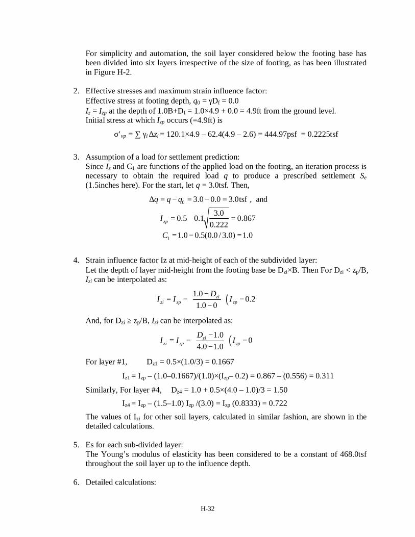
1. Sub-division of subsurface layers:
For simplicity and automation, the soil layer considered below the footing base has been divided into six layers irrespective of the size of footing as illustrated in Figure H-2. Here, L/B = 1. Hence zp = 0.5B = 2.45ft and D = 2.0B = 9.8ft.
Strain influence factor,
Iz
Dep
th b
elow
foot
ing,
z
Izp
zp
D
0zp / 3
(D − zp) / 3
zp / 3zp / 3
(D − zp) / 3
(D − zp) / 3
Figure H-2. Subsurface layer division for Schmertmann (1978) method
2. Effective stresses and maximum strain influence factor: Effective stress at footing depth, q0 = γDf = 124.9 × 7.55 = 943.0psf = 0.4715tsf Iz = Izp at the depth of 0.5B+Df = 0.5×4.9 + 7.55 = 10.0ft from the ground level.

H-12
Initial stress at which Izp occurs (=10.0ft) is σ′vp = ∑ γi ∆zi
= 124.9×2.5 + 124.9×(5.0–2.5) + 124.9×(7.5–5.0) + 124.9×(10.0–7.5) = 1249psf = 0.6245tsf
3. Assumption of a load for settlement prediction:
Since Iz and C1 are functions of the applied load on the footing, an iteration process is necessary to obtain the required load q to produce a prescribed settlement Se (1.5inches here). For the start, let q = 3.0tsf. Then,
3.0 0.4715 2.53tsfq∆ = − = , and
2.530.5 0.1 0.7010.6245zpI = + =
1 1.0 0.5(0.4715 / 2.53) 0.9068 0.5C = − = >
4. Strain influence factor Iz at mid-height of each of the subdivided layer:
Let the depth of layer mid-height from the footing base be Dzi×B. Then For Dzi < zp/B, Izi can be interpolated as:
( )0.50.1
0.5 0zi
zi zp zpDI I I− = − − −
And, for Dzi ≥ zp/B, Izi can be interpolated as:
( )0.50
2.0 0.5zi
zi zp zpDI I I− = − − −
For layer #1, Dz1 = 0.5×(0.5/3) = 0.0833
Iz1 = Izp – 2 (0.5–0.0833)×(Izp– 0.1) = 0.701 – (–0.5010) = 0.2002
Similarly, For layer #4, Dz4 = 0.5 + 0.5×(2.0 – 0.5)/3 = 0.75 Iz4 = Izp – (0.75–0.5) Izp / (1.5) = Izp (0.8333) = 0.5843
The values of Izi for other soil layers, calculated in similar fashion, are shown in the detail calculations.
5. Es for each sub-divided layer:
The Young’s modulus of elasticity has been taken as the weighted average of each soil layer present in the subsurface below the footing base, which has been subdivided as shown in Figure H-2. For layer #1 to #3, Es = 188.85tsf (since zp < 10.1ft from the ground surface, ref. Table H-9). For layer #4, the depth ranges from 10.0ft (= zp+ Df) to 12.5ft (= zp+ (D–zp)/3 + Df). Hence, the weighted average of Es , considered to be at the mid-height of layer 4, is obtained from Table H-9 as:

H-13
188.85(10.1 10.0) 183.13(12.5 10.1)avg 183.30tsf(12.5 10.0)sE − + −
= =−
and so on for other layers.
6. Detailed calculations: After the sum of (Iz / Es)×∆z is obtained, the resulting settlement can be calculated using Equation (H-8). The detailed calculation is shown below. The calculation is repeated with trial applied loads q until the required settlement is obtained.
B (ft) = 4.9
From GL, zp (ft) = 10.0From GL, D (ft) = 17.4
σ'vp (tsf) = 0.6245q0 (tsf) = 0.4715
Trail 1:
Let q (tsf) = 3.00Then ∆q = 2.53
Izp = 0.7012C1 = 0.9068C2 = 1.0000
Subdivided Layer #
Depth below GL
(ft)
Depth below footing base
(ft)
Layer thickness
∆z (ft)
Mid-height depth below footing base
Dz (ft)
Strain influence factor, Iz
Average Es (tsf) Iz/ Es * ∆z
1 8.4 0.817 0.817 0.408 0.2002 188.85 0.0008662 9.2 1.633 0.817 1.225 0.4006 188.85 0.0017323 10.0 2.450 0.817 2.042 0.6010 188.85 0.0025994 12.5 4.900 2.450 3.675 0.5843 183.30 0.0078105 14.9 7.350 2.450 6.125 0.3506 308.28 0.0027866 17.4 9.800 2.450 8.575 0.1169 259.06 0.001105
sum: 0.016899Se (in) = 0.465

H-14
Example of a next trial:
Let q (tsf) = 7.04Then ∆q = 6.57
Izp = 0.8243C1 = 0.9641C2 = 1.0000
Subdivided Layer #
Depth below GL
(ft)
Depth below footing base
(ft)
Layer thickness
∆z (ft)
Mid-height depth below footing base
Dz (ft)
Strain influence factor, Iz
Average Es (tsf) Iz/ Es * ∆z
1 8.4 0.817 0.817 0.408 0.2207 188.85 0.0009542 9.2 1.633 0.817 1.225 0.4621 188.85 0.0019983 10.0 2.450 0.817 2.042 0.7036 188.85 0.0030424 12.5 4.900 2.450 3.675 0.6869 183.30 0.0091815 14.9 7.350 2.450 6.125 0.4121 308.28 0.0032756 17.4 9.800 2.450 8.575 0.1374 259.06 0.001299
sum: 0.019751Se (in) = 1.500
Hence, for a footing of width 4.9ft, a load of 7.0tsf is estimated to produce a settlement of 1.5in using Schmertmann (1978) method. The load required to produce a settlement of 1.5in for other footing sizes can be obtained in similar fashion.
H.1.5.4 Hough (1959) Method
The settlement below a footing is estimated as:
0
1 0
1 ln'
nv i vi
e ii i v i
S zC=
σ + ∆σ= ∆ σ
∑ (H-10)
where C′i is bearing capacity index obtained based on corrected (N1)60 value from Figure H-3 ( = (1 + e0) / Cc ; e0 is initial void ratio and Cc is virgin compressibility index); ∆zi is the layer thickness of layer i, σv0i is initial effective overburden pressure and ∆σvi change in effective vertical stress both at mid-height of layer i, n is the number of layers present within the influence depth below the footing base.

H-15
Figure H-3. Bearing capacity index versus corrected SPT value (= (N1)60) (Cheney and Chassie 1982, modified from Hough 1959)
1. Bearing capacity index C′ based on corrected SPT value at layer mid-height: In the calculation presented here, the value of C′ has taken from digitized and fitted curves of Figure H-3 for automation. The curve fittings are listed in Table H-10 below.
Table H-10. Bearing capacity index from corrected SPT values based on Figure H-3
Soil description Fitted curve from Figure H-3
Clean uniform med Sand C′ = 0.0746(N1)602 + 0.1313(N1)60 + 51.157
Well graded silty Sand and Gravel C′ = 0.0335(N1)602 + 0.8276(N1)60 + 42.86
Clean well-graded fine to coarse Sand C′ = 0.0002(N1)603 - 0.01(N1)60
2 + 2.1694(N1)60 + 27.145 Well-graded fine to medium silty Sand C′ = 0.009(N1)60
2 + 1.3134(N1)60 + 28.052 Sandy Clay C′ = 0.0052(N1)60
2 + 1.1066(N1)60 + 24.928 Inorganic Silt C′ = 0.0022(N1)60
2 + 1.2166(N1)60 + 16.49

H-16
A soil layer has been taken as the layer for each SPT observation present, e.g. layer numbers 2.1 and 2.2 shown in Table H-11 are two layers.
Table H-11. Bearing capacity index C′ for each soil layer
Layer # Depth (ft) N60
Mid-layer overburden
σv0 (tsf)
(N1)60 (Liao and Whitmann 1996)
Soil description
BC index C'
1.1 2.5 6 0.079 21.371.2 5.0 7 0.235 14.431.3 7.5 18 0.392 28.752.1 10.1 20 0.550 26.98 70.02.2 12.6 22 0.707 26.16 68.62.3 15.1 42 0.864 45.19 105.83a.1 20.0 38 1.095 36.31 87.63a.2 24.9 47 1.402 39.69 94.43a.3 29.9 33 1.709 25.24 66.93b.1 34.8 45 1.939 32.31 79.93b.2 39.7 49 2.093 33.87 82.94.1 44.6 42 2.246 28.02 113.44.2 49.5 37 2.400 23.88 96.8
Lean clay
silty sand
well graded sand
(taken as fine to med.)
clean uniform sand
2. Increase in stress at each layer mid-height: The increase in stress at layer mid-height is obtained using 2:1 method of stress distribution. This method approximates the vertical stress ∆σv at a depth z which is caused by a footing of dimension L×B loaded with a force Q as the following.
( )( )v
QB z L z
∆σ =+ +
(H-11)
3. Settlement in each layer and total settlement:
The influence depth has been taken according to Table H-8. For a square footing of B = 4.9ft placed at and embedment depth Df of 7.55ft, influence depth from the ground surface is 17.35ft. Further, as ∆σv is directly related to the applied load Q, it is easier to estimate the required load to produce a prescribed settlement of 1.5in by hit and trial. For the start, trial 1, an applied vertical stress of 3tsf is assumed at the footing base. The detailed calculations using Equations (H-10) and (H-11) and the bearing capacity index C′ from Table H-11 are presented below.

H-17
B (ft) = 4.9L (ft) = 4.9
Depth of influence from GL (ft) = 2B + Df = 17.35
Trial 1:
Let q (tsf) = 3.00Then,
applied load (ton) = 72.03
Layer # Depth (ft)
Layer thickness
∆z (ft)
Depth of layer mid-height from
footing base z (ft)
Initial effective vertical stress at layer mid-height,
σv 0 (tsf)
Increase in pressure at layer
mid-height ∆σv (tsf)
Bearing capacity index
C'
Settlement in each layer
∆H (in)
1.1 2.51.2 5.01.3 7.52.1 10.1 2.5 1.3 0.550 1.899 70.04 0.28092.2 12.6 2.5 3.8 0.707 0.955 68.57 0.16412.3 15.1 2.5 6.3 0.864 0.575 105.79 0.06273a.1 17.4 2.3 8.7 1.013 0.391 90.48 0.0425
sum: 0.550
Se (in) = 0.550 Example of a next trial:
Let q (tsf) = 23.40Then,
applied load (ton) = 561.83
Layer # Depth (ft)
Layer thickness
∆z (ft)
Depth of layer mid-height from footing base, z
(ft)
Initial effective vertical stress at layer mid-height,
σv 0 (tsf)
Increase in pressure at layer mid-height, ∆σv
(tsf)
Bearing capacity index
C'
Settlement in each layer
∆H (in)
1.1 2.51.2 5.01.3 7.52.1 10.1 2.5 1.3 0.550 14.811 70.04 0.62612.2 12.6 2.5 3.8 0.707 7.448 68.57 0.46952.3 15.1 2.5 6.3 0.864 4.483 105.79 0.22383a.1 17.4 2.3 8.7 1.013 3.051 90.48 0.1807
sum: 1.500
Se (in) = 1.500
For a footing of width 4.9ft, a load of 16.35tsf is estimated to produce a settlement of 1.5in using Hough (1959) method. The load required to produce a settlement of 1.5in for other footing sizes can be estimated in a similar fashion.

H-18
H.1.6 Resistance Factors
The footing will be constructed on the in-situ soil stratum (natural soil condition) without replacing the silty sand layer with an engineering fill. Hence the resistance factors to be used are the ones given for natural deposited granular soil condition. The newly proposed factors developed in this research for Strength-I design corresponding to the inclined-eccentric positive eccentricity loading condition are as shown in Table H-12, which varies according to the average soil friction angle of the granular material considered. It can be seen that the resistance factor is expected to be essentially 0.40, as φ = 0.35 is applicable for either very small or large footings. The resistance factor in the current AASHTO (2007) specification is given as φ = 0.45 and has been presented here for comparison. No resistance factors exist in the current specifications for Service limit state, hence, the estimated load required to produce a settlement of 1.5in has been left unfactored.
Table H-12 Average soil friction angle and recommended resistance factor variation according to the footing size (thereby the influence depth)
B (ft) Average φf (deg)
Recommended φ B (ft) Average
φf (deg) Recommended
φ 2.95 35.60 0.35 12.80 36.60 0.40 3.94 36.45 0.35 13.78 36.59 0.40 4.92 36.64 0.40 14.76 36.61 0.40 5.91 36.77 0.40 15.75 36.62 0.40 6.89 36.93 0.40 16.73 36.57 0.40 7.87 37.09 0.40 17.72 36.51 0.35 8.86 37.14 0.40 18.70 36.44 0.35 9.84 36.89 0.40 19.68 36.33 0.35
10.83 36.68 0.40 20.67 36.23 0.35 11.81 36.61 0.40
H.1.7 Design Footing Width
The load eccentricities according to Table H-3 are: for the Strength-I limit state across the footing length eL = 0.335 ft and across the footing width eB = 0.220 ft, and for the Service-I limit state: eL = 0.358 ft and eB = 0.226 ft. The maximum load eccentricity for design is hence 0.358 ft. Hence the minimum admissible footing width is B = 2.15ft (= eB×6 = 0.358ft×6). At this stage, the footing is designed for Strength-I and Service-I vertical loads. The maximum vertical factored load for Strength-I limit state (bearing resistance - see Table H-5.1) is 2780 kips, and the vertical unfactored load is 2140 kips for Service-I limit state (bearing resistance and sliding resistance see Table H-5.1 and H-5.2).
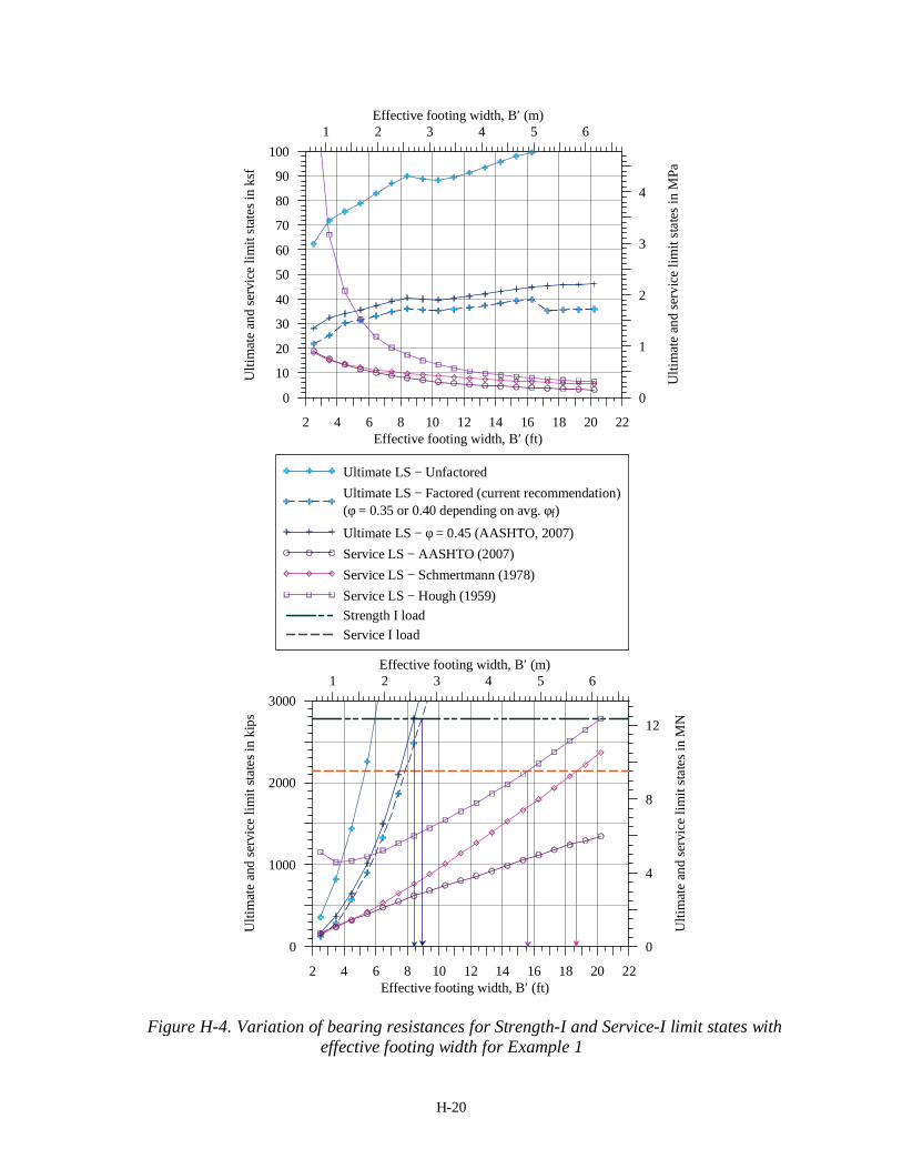
Figure H-4 presents the unfactored as well as the factored bearing resistances for different effective footing widths. The bearing loading intensities (stresses) are plotted in the upper figure, whereas the lower ones present the bearing loads. The footing width refers to the effective width for both bearing capacity and settlement analyses. While the settlement analyses were carried out

H-19
for the geometrical (full) foundation width, in the presentation of Figure H-4, the width was transformed to be the effective width.
Applying the aforementioned vertical loads to the corresponding limit states in Figure H-4 results with the following: (a) the unfactored strength limit states is satisfied by a footing size of 6.75×6.75ft (full geometrical size = 6 + 2×0.36), and (b) the unfactored allowable bearing resistance obtained using Hough (1959) method results in footing dimensions of 16.25 ft ×16.25 ft and using Schmertmann (1978) method results in dimensions of 19.50 ft×19.50 ft, whereas, AASHTO (2007) method results with a much larger footing. The original example (FHWA GEC – Example 1) resulted with a full geometrical foundation size of 16.5×16.5ft based on the Hough method, which is close to the foundation size obtained here. For the factored Strength-I bearing resistance, a square footing of 9.75ft side meets the requirement of all resistance factors criteria, whereas, to meet the factored Service-I bearing resistances demand, a footing larger than the relations presented in the figure (effective width of 21.0 ft) is necessary. Extrapolating the trend in Service-I bearing resistance, a square footing of about 50.0ft side is required.
The conclusions from Figure H-4 are, therefore:
1. Based on strength limit state alone; the following foundation sizes are sufficient: • Strength limit state φ = 0.35 to 0.40: 9.75ft×9.75 ft • Strength limit state φ = 0.45: 9.25×9.25 ft
2. Based on unfactored serviceability limit state (current AASHTO); a minimum footing size of 16.25×16.25ft is required.
H-20
2 4 6 8 10 12 14 16 18 20 22Effective footing width, B′ (ft)
0
1000
2000
3000
Ulti
mat
e an
d se
rvic
e lim
it sta
tes i
n ki
ps
1 2 3 4 5 6Effective footing width, B′ (m)
0
4
8
12
Ulti
mat
e an
d se
rvic
e lim
it st
ates
in M
N
2 4 6 8 10 12 14 16 18 20 22Effective footing width, B′ (ft)
0
10
20
30
40
50
60
70
80
90
100
Ulti
mat
e an
d se
rvic
e lim
it st
ates
in k
sf
1 2 3 4 5 6Effective footing width, B′ (m)
0
1
2
3
4
Ulti
mat
e an
d se
rvic
e lim
it st
ates
in M
Pa
Ultimate LS − UnfactoredUltimate LS − Factored (current recommendation)(φ = 0.35 or 0.40 depending on avg. φf)Ultimate LS − φ = 0.45 (AASHTO, 2007)Service LS − AASHTO (2007)Service LS − Schmertmann (1978)Service LS − Hough (1959)Strength I loadService I load
Figure H-4. Variation of bearing resistances for Strength-I and Service-I limit states with effective footing width for Example 1

H-21
H.1.8 Sliding Resistance
The footing is poured on site; hence, the recommended resistance factors for cast in-place footings to be used for sliding resistance are φτ = 0.40 when lateral load due to at-rest earth pressure is acting and φτ = 0.45 when lateral load due to active earth pressure is acting. The relation between soil-footing friction angle δs and soil friction angle is tanδs = 0.91tanφf for cast in-place footings. Hence, for φf = 34.5°, nominal sliding resistance, F2τ = F1 × tan(δs) = F1 × 0.91tan(34.5). The minimum factored vertical load for the designed footing width for Strength-I and Service-I load for sliding (Table H-5.2) is 2137.2kips (Service-I), for which the lateral load is 51.2kips. That is, Factored sliding resistance, φτF2τ = 0.40 × 2137.2 × 0.91tan(34.5) = 534.7kips > 51.2kips. Hence the designed footing is safe in sliding. H.1.9 Discussions and Conclusions
It can be seen from Figure H-4 that Service limit states govern the footing dimension in this design example. While the ultimate limit state (Strength I) can be satisfied with a foundation size of 9.75×9.75ft (considering all possibilities), the serviceability limit state requires a foundation size of at least 16.25×16.25ft. The AASTHO (2007) method gives the most conservative estimate of the allowable load for the given allowable 1.5inch settlement. Schmertmann (1978) method gives allowable loads comparable to those obtained using the AASHTO method for smaller footings, while it gives the allowable loads closer to those obtained using Hough (1959) method as the footing width increases. For that reason, one can conclude that: (i) the recommended new strength limit state factors would not affect this design example as it is controlled by the service limit, and (ii) if resistance factors were to be applied to the service limit, for the given example and a limit settlement of 1.5inch the foundation size would increase significantly.

H-22
H.2 EXAMPLE 2: BILLERICA BRIDGE, CENTRAL PIER ON GRAVEL FILL H.2.1 General Information
The central pier and the east abutment of the Billerica B-12-025 (2004) bridge are analyzed in examples 2 and 3, respectively. Billerica bridge B-12-025 (2004) is a 2-span, continuous medium length span (CM-M); skewed structure with a skew angle of 20°-13′-32″. The bridge dimensions and the footing dimensions used are:
Bridge:
Span lengths 112.8ft-112.8ft (34.4m-34.4m) Span width 49.0ft (14.93m)
Foundations: East Abutment width = 12.5ft (3.8m); length = 61.65ft (18.79m); average height of abutment from abutment footing base = 23.4ft
(7.14m); footing thickness = 2.95ft (0.9m); abutment wingwall –acute side = 42.45ft (12.94m), obtuse side = 41.34ft (12.60m)
Central Pier width = 13.12ft (4.0m); length = 52.4ft (15.96m); thickness = 3.28ft (1.0m);
given maximum bearing pressure = 37.6ksf (1800kPa) for Strength LS (factored bearing pressure = 13.16ksf or 630kPa), and 6.27ksf (300kPa) for Service LS for allowable settlement of maximum 1.5inches (38mm)
West Abutment width = 12.5ft (3.8m); length = 61.65ft (18.79m); height of abutment from abutment footing base = 23.4ft (7.14m);
footing thickness = 2.95ft (0.9m); abutment wingwall –acute side = 36.2ft (11.04m), obtuse side = 30.85ft (9.40m)
H.2.2 Subsurface Condition
The subsurface at the central pier location consists (based on boring GB-22) approximately of 3ft of loose granular fill overlaying 5.5ft of very dense coarse sand and gravel overlaying a rock layer. The geotechnical report (URS, 2001) called for the replacement of the loose fill with gravel borrow material that would extend to the proposed footing elevation. As such, the foundation design follows the geotechnical report assuming the central pier to be founded on compacted gravel. The parameters provided for the gravel borrow in the geotechnical report are: bulk unit weight γ (γ') = 120.0 pcf (63.65 pcf) (18.85/9.99 kN/m³), internal friction angle of 38° and interfacial friction angle between the footing base and the soil δs = 29.7°. The groundwater table is located at elevation 157.5 ft (48.0 m) and the foundation base is at elevation of 160.1ft (48.8m).
H.2.3 Loads, Load Combinations and Limit States
The different load components as provided are summarized in Table H-13. The weight of the
footing and the soil above the footing has been considered as a vertical centric load of 519.2kips in addition to the vertical load component F1.
H-23
Table H-14 summarizes the investigated load combinations and the resultant characteristic loading as well as the resultant load inclination 1
23
22 FFF + and eccentricity in both directions
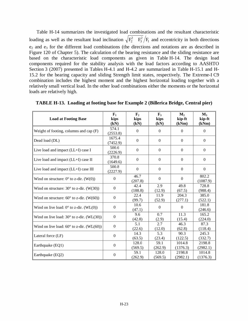
e2 and e3 for the different load combinations (the directions and notations are as described in Figure 120 of Chapter 5). The calculation of the bearing resistance and the sliding resistance are based on the characteristic load components as given in Table H-14. The design load components required for the stability analysis with the load factors according to AASHTO Section 3 (2007) presented in Tables H-4.1 and H-4.2 are summarized in Table H-15.1 and H-15.2 for the bearing capacity and sliding Strength limit states, respectively. The Extreme-I C9 combination includes the highest moment and the highest horizontal loading together with a relatively small vertical load. In the other load combinations either the moments or the horizontal loads are relatively high.
TABLE H-13. Loading at footing base for Example 2 (Billerica Bridge, Central pier)
Load at Footing Base F1
kips (kN)
F2 kips (kN)
F3 kips (kN)
M2 kip-ft (kNm)
M3 kip-ft (kNm)
Weight of footing, columns and cap (F) 574.1 (2553.8) 0 0 0 0
Dead load (DL) 1675.4 (7452.9) 0 0 0 0
Live load and impact (LL+I) case I 500.6 (2226.9) 0 0 0 0
Live load and impact (LL+I) case II 370.8 (1649.6) 0 0 0 0
Live load and impact (LL+I) case III 500.8 (2227.9) 0 0 0 0
Wind on structure: 0° to z-dir. (W(0)) 0 46.7 (207.8) 0 0 802.2
(1087.9)
Wind on structure: 30° to z-dir. (W(30)) 0 42.4 (188.8)
2.9 (12.9)
49.8 (67.5)
728.8 (988.4)
Wind on structure: 60° to z-dir. (W(60)) 0 22.4 (99.7)
11.9 (52.9)
204.3 (277.1)
385.0 (522.1)
Wind on live load: 0° to z-dir. (WL(0)) 0 10.6 (47.1) 0 0 181.8
(246.6)
Wind on live load: 30° to z-dir. (WL(30)) 0 9.6 (42.8)
0.7 (2.9)
11.3 (15.4)
165.2 (224.0)
Wind on live load: 60° to z-dir. (WL(60)) 0 5.1 (22.6)
2.7 (12.0)
46.3 (62.8)
87.3 (118.4)
Lateral force (LF) 0 14.3 (63.5)
5.3 (23.4)
90.3 (122.5)
245.3 (332.7)
Earthquake (EQ1) 0 128.0 (569.5)
59.1 (262.9)
1014.8 (1376.3)
2198.8 (2982.1)
Earthquake (EQ2) 0 59.1 (262.9)
128.0 (569.5)
2198.8 (2982.1)
1014.8 (1376.3)

H-24
TABLE H-14. Load combinations and resultant characteristic (unfactored) loading for Example 2
Load
Combi-nations
Load Components F1
kips (kN)
F2 kips (kN)
F3 kips (kN)
M2 kips-ft (kNm)
M3 kips-ft (kNm) 1
23
22
FFF +
e2 = M3/F1 ft
(m)
e3 = M2/F1 ft
(m)
C1 F+DL + (L+I(caseII)) 2620.3 (11656.3) 0.0 0.0 0.0 0.0 0.000 0.000 0.000
C2 F+DL + (LL+I(caseIII))
2750.3 (12234.6) 0.0 0.0 0.0 0.0 0.000 0.000 0.000
C3 F+DL + (LL+I(caseII)) + W(0)
2620.3 (11656.3)
46.7 (207.8) 0.0 0.0 802.2
(1087.9) 0.018 0.305 (0.093) 0.000
C4 F+DL + (LL+I(caseII)) + W(60)
2620.3 (11656.3)
22.4 (99.7)
11.9 (52.9)
204.3 (277.1)
385.0 (522.1) 0.010 0.148
(0.045) 0.079
(0.024)
C5 F+DL + (LL+I(caseII)) + W(0) + WL(0)
2620.3 (11656.3)
57.3 (254.9) 0.0 0.0 984.0
(1334.6) 0.022 0.374 (0.114) 0.000
C6 F+DL + (LL+I(caseII)) + W(60) + WL(60)
2620.3 (11656.3)
27.5 (122.3)
14.6 (64.9)
250.6 (339.9)
472.3 (640.6) 0.012 0.180
(0.055) 0.095
(0.029)
C7 F+DL + (LL+I(caseII)) + W(0) + WL(0) + LF
2620.3 (11656.3)
71.6 (318.4)
5.3 (23.4)
90.3 (122.5)
1229.3 (1667.3) 0.027 0.469
(0.143) 0.036
(0.011)
C8
F+DL + (LL+I(caseII)) + W(60) + WL(60) + LF
2620.3 (11656.3)
41.8 (185.9)
19.9 (88.3)
341.0 (462.4)
717.6 (973.3) 0.018 0.272
(0.083) 0.131
(0.040)
C9 F+DL + (LL+I(caseII)) + EQ1
2620.3 (11656.3)
128.0 (569.5)
59.1 (262.9)
1014.8 (1376.3)
2198.8 (2982.1) 0.054 0.840
(0.256) 0.387
(0.118)
C10 F+DL + (LL+I(caseII)) + EQ2
2620.3 (11656.3)
59.1 (262.9)
128.0 (569.5)
2198.8 (2982.1)
1014.8 (1376.3) 0.054 0.387
(0.118) 0.840
(0.256)

H-25
TABLE H-15.1. Load combinations and resultant design (factored) loading required for bearing resistance
Load
Combinations F1
kips(kN) F2
kips(kN) F3
kips(kN) M2
kip-ft (kNm) M3
kip-ft (kNm) Service-I C1 2620.3 (11656.3) 0.00 0.0 0.0 0.0 Service-I C2 2750.3 (12234.6) 0.00 0.0 0.0 0.0 Service-I C3 2620.3 (11656.3) 14.0 (62.3) 0.0 0.0 240.7 (326.4) Service-I C4 2620.3 (11656.3) 6.7 (29.9) 3.6 (15.9) 61.3 (83.1) 115.5 (156.6) Service-I C5 2620.3 (11656.3) 24.6 (109.4) 0.0 0.0 422.5 (573.0)
Service-I C6 2620.3 (11656.3) 11.8 (52.5) 6.3 (27.9) 107.6 (146.0) 202.8 (275.1) Strength-I C1 3460.8 (15395.2) 0.0 0.0 0.0 0.0 Strength-I C2 3688.3 (16407.2) 0.0 0.0 0.0 0.0 Strength-I C7 3460.8 (15395.2) 25.0 (111.2) 9.2(41.0) 158.1 (214.4) 429.3 (582.2) Strength-V C5 3312.5 (14735.3) 29.3 (130.2) 0.0 0.0 502.7 (681.8) Strength-V C6 3312.5 (14735.3) 14.1 (62.5) 7.5 (33.2) 128.1 (173.7) 241.3 (327.3) Strength-V C7 3312.5 (14735.3) 48.6 (216.0) 7.1 (31.6) 122.0 (165.4) 833.9 (1130.9) Strength-V C8 3312.5 (14735.3) 33.3 (148.3) 14.6 (64.8) 250.0 (339.1) 572.5 (776.4)
Extreme-I C9 3182.7 (14158.0) 128.0 (569.5) 59.1 (262.9) 1014.8 (1376.3) 2198.8 (2982.1) Extreme-I C10 3182.7 (14158.0) 59.1 (262.9) 128.0 (569.5) 2198.8 (2982.1) 1014.8 (1376.3)
TABLE H-15.2. Load combinations and resultant design (factored) loading required for
sliding resistance
Load Combinations
F1 kips(kN)
F2 kips(kN)
F3 kips(kN)
M2 kip-ft (kNm)
M3 kip-ft (kNm)
Service-I C3 2620.3 (11656.3) 14.0 (62.3) 0.0 0.0 240.7 (326.4) Service-I C4 2620.3 (11656.3) 6.7 (29.9) 3.6 (15.9) 61.3 (83.1) 115.5 (156.6) Service-I C5 2620.3 (11656.3) 24.6 (109.4) 0.0 0.0 422.5 (573.0)
Service-I C6 2620.3 (11656.3) 11.8 (52.5) 6.3 (27.9) 107.6 (146.0) 202.8 (275.1) Strength-I C7 2673.5 (11892.8) 25.0 (111.2) 9.2(41.0) 158.1 (214.4) 429.3 (582.2) Strength-V C5 2525.2 (11233.0) 29.3 (130.2) 0.0 0.0 502.7 (681.8) Strength-V C6 2525.2 (11233.0) 14.1 (62.5) 7.5 (33.2) 128.1 (173.7) 241.3 (327.3) Strength-V C7 2525.2 (11233.0) 48.6 (216.0) 7.1 (31.6) 122.0 (165.4) 833.9 (1130.9) Strength-V C8 2525.2 (11233.0) 33.3 (148.3) 14.6 (64.8) 250.0 (339.1) 572.5 (776.4) Extreme-I C9 2395.4 (10655.6) 128.0 (569.5) 59.1 (262.9) 1014.8 (1376.3) 2198.8 (2982.1) Extreme-I C10 2395.4 (10655.6) 59.1 (262.9) 128.0 (569.5) 2198.8 (2982.1) 1014.8 (1376.3)

H-26
H.2.4 Nominal Bearing Resistances at the Limit State H.2.4.1 Footing Information:
The footing length is kept fixed at 52.4 ft, which is comparable to the bridge span width, and is assumed to have no embedment depth. The bearing resistances of footings with length fixed and widths varied from 2.95ft to 20.70ft have been calculated.
The load combinations considered for the bearing resistance estimation of the rectangular footings are Strength-I C7 and Strength-I C2 limit states according to AASHTO (2007) with an embedment depth equal to zero. The Strength-I C7 limit state has the 2-way load inclination and 2-way load eccentricity with the highest load inclination as well as the highest load eccentricity along the footing width among the possible load combinations considered, whereas, Strength-I C2 limit state has the highest unfactored as well as factored vertical-centric loading (Tables H-14 and H-15).
For Strength-I C7 LS, the maximum load eccentricities along the footing width and the footing length are 0.469ft and 0.034ft, respectively. Detailed calculations for an example footing of width B = 4.9ft are presented here. The effective footing dimensions for the C7 limit state are as follows
Effective width B' = B – 2e2 = 4.9 – 2×0.469 = 3.98ft
Effective length L' = L – 2e3 = 52.4 – 2×0.034 = 52.3ft Here, the eccentricity ratios across the footing length (e3/L, Table H-14) are very small, even
for load combination C10 related to Extreme-I loading conditions (a maximum of 0.016). Hence, the effect of the load eccentricity across the footing length can be neglected for practical purposes for this example, however, the calculations have been presented using the effective length.
H.2.4.2 Bearing Capacity Factors
Since the average φf has been assumed to be 38.0°, the bearing capacity factors are as follows.
Nq = exp{π tan(38.0)} tan2(45+38.0/2) = 48.93 , and Nγ = 2 (48.93+1) tan(38.0) = 78.02 H.2.4.3 Bearing Capacity Modification Factors
Shape factors for Strength-I C7 LS:
1 tan ( / ) 1 tan(38)(3.98 / 52.29) 1.060q fs B L′ ′= + φ = + = 1 0.4( '/ ') 1 0.4(3.98 / 52.29) 0.970s B Lγ = − = − =
Depth factors: The footing is assumed to be on the ground surface, i.e. Df = 0. Hence, dq = 1.0.
Load inclination factors for Strength-I C7 LS: Here, the projected direction of the inclined load in the plane of the footing is given by

H-27
θ = tan-1(F3/F2) = tan-1(5.3/71.6) = 4.233. Hence
2 22 52.29 / 3.98 2 3.98 / 52.29cos (4.233) sin (4.233) 1.0751 52.29 / 3.98 1 3.98 / 52.29
n + + = + = + +
Then
1.075
2 271.6 5.31 0.9712620.3 0qi
+= − =
+ and
(1.075 1)
2 271.6 5.31 0.9442620.3 0
i+
γ
+= − =
+
H.2.4.4 Modified Bearing Capacity Factors for Strength-I C7 LS
Nqm = Nqsqdqiq= 48.93×1.060×1.0×0.971 = 50.32 and Nγm = Nγsγiγ = 78.02×0.970×0.944 = 71.41 H.2.4.5 Groundwater Table Modification Factors Here, Df = 0.0 < Dw (=2.6ft). Hence,
γ1 = γ For B = 4.9ft, 1.5B+Df = 4.9 + 0.0 = 4.9ft > 2.6ft (GWT). Therefore,
262.4 2.6 0.01 1 120.1 1.0 1 79.8pcf
1.5 120.1 1.5 4.9w fw D D
B − γ − γ = γ − − = − − = γ ×
H.2.4.6 Bearing Capacity for Strength-I C7 LS
Hence, the nominal (unfactored) bearing resistance of the footing of width 4.9ft calculated using the bearing capacity equation given in AASHTO (2007) is
1 20.5
0 0 0.5 79.8 3.98 71.41 11.36ksfu cm f qm mq cN D N B Nγ′= + γ + γ
= + + × × × =
Table H-16(a) presents the details of the nominal bearing capacity calculation for Strength-I, combination C7 loading in which the load is 2-way inclined and 2-way eccentric, and Table H-16(b) presents the details for Strength-I combination C2 loading in which the load is vertical-centric for footing of length 52.4ft and widths varying from 2.95ft to 20.67ft.
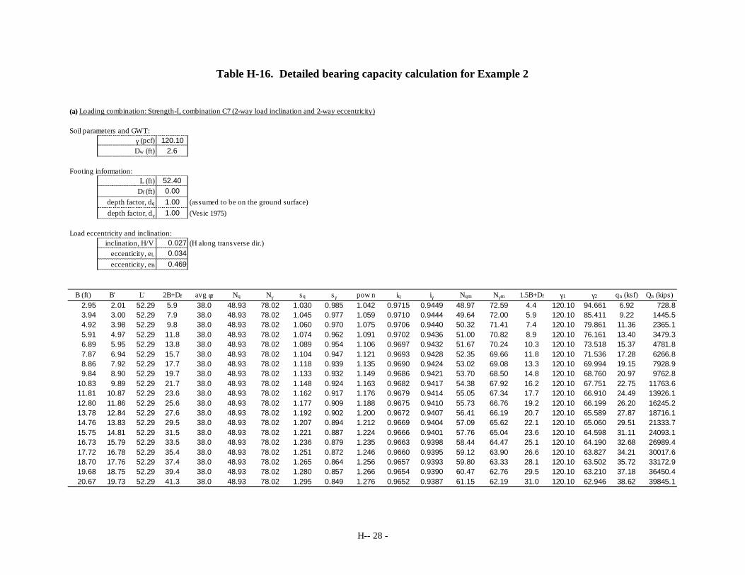
H-- 28 -
Table H-16. Detailed bearing capacity calculation for Example 2 (a) Loading combination: Strength-I, combination C7 (2-way load inclination and 2-way eccentricity)
Soil parameters and GWT:120.10
2.6
Footing information:52.400.001.00 (assumed to be on the ground surface)1.00 (Vesic 1975)
Load eccentricity and inclination:0.027 (H along transverse dir.)0.0340.469
B (ft) B' L' 2B+Df avg φf Nq Nγ sq sγ pow n iq iγ Nqm Nγm 1.5B+Df γ1 γ2 qn (ksf) Qn (kips)2.95 2.01 52.29 5.9 38.0 48.93 78.02 1.030 0.985 1.042 0.9715 0.9449 48.97 72.59 4.4 120.10 94.661 6.92 728.83.94 3.00 52.29 7.9 38.0 48.93 78.02 1.045 0.977 1.059 0.9710 0.9444 49.64 72.00 5.9 120.10 85.411 9.22 1445.54.92 3.98 52.29 9.8 38.0 48.93 78.02 1.060 0.970 1.075 0.9706 0.9440 50.32 71.41 7.4 120.10 79.861 11.36 2365.15.91 4.97 52.29 11.8 38.0 48.93 78.02 1.074 0.962 1.091 0.9702 0.9436 51.00 70.82 8.9 120.10 76.161 13.40 3479.36.89 5.95 52.29 13.8 38.0 48.93 78.02 1.089 0.954 1.106 0.9697 0.9432 51.67 70.24 10.3 120.10 73.518 15.37 4781.87.87 6.94 52.29 15.7 38.0 48.93 78.02 1.104 0.947 1.121 0.9693 0.9428 52.35 69.66 11.8 120.10 71.536 17.28 6266.88.86 7.92 52.29 17.7 38.0 48.93 78.02 1.118 0.939 1.135 0.9690 0.9424 53.02 69.08 13.3 120.10 69.994 19.15 7928.99.84 8.90 52.29 19.7 38.0 48.93 78.02 1.133 0.932 1.149 0.9686 0.9421 53.70 68.50 14.8 120.10 68.760 20.97 9762.8
10.83 9.89 52.29 21.7 38.0 48.93 78.02 1.148 0.924 1.163 0.9682 0.9417 54.38 67.92 16.2 120.10 67.751 22.75 11763.611.81 10.87 52.29 23.6 38.0 48.93 78.02 1.162 0.917 1.176 0.9679 0.9414 55.05 67.34 17.7 120.10 66.910 24.49 13926.112.80 11.86 52.29 25.6 38.0 48.93 78.02 1.177 0.909 1.188 0.9675 0.9410 55.73 66.76 19.2 120.10 66.199 26.20 16245.213.78 12.84 52.29 27.6 38.0 48.93 78.02 1.192 0.902 1.200 0.9672 0.9407 56.41 66.19 20.7 120.10 65.589 27.87 18716.114.76 13.83 52.29 29.5 38.0 48.93 78.02 1.207 0.894 1.212 0.9669 0.9404 57.09 65.62 22.1 120.10 65.060 29.51 21333.715.75 14.81 52.29 31.5 38.0 48.93 78.02 1.221 0.887 1.224 0.9666 0.9401 57.76 65.04 23.6 120.10 64.598 31.11 24093.116.73 15.79 52.29 33.5 38.0 48.93 78.02 1.236 0.879 1.235 0.9663 0.9398 58.44 64.47 25.1 120.10 64.190 32.68 26989.417.72 16.78 52.29 35.4 38.0 48.93 78.02 1.251 0.872 1.246 0.9660 0.9395 59.12 63.90 26.6 120.10 63.827 34.21 30017.618.70 17.76 52.29 37.4 38.0 48.93 78.02 1.265 0.864 1.256 0.9657 0.9393 59.80 63.33 28.1 120.10 63.502 35.72 33172.919.68 18.75 52.29 39.4 38.0 48.93 78.02 1.280 0.857 1.266 0.9654 0.9390 60.47 62.76 29.5 120.10 63.210 37.18 36450.420.67 19.73 52.29 41.3 38.0 48.93 78.02 1.295 0.849 1.276 0.9652 0.9387 61.15 62.19 31.0 120.10 62.946 38.62 39845.1
eccenticity, eB
γ (pcf)Dw (ft)
inclination, H/V eccenticity, eL
depth factor, dq
depth factor, dγ
L (ft)Df (ft)

H-- 29 -
Table H-16 continued. (b) Loading combination: Strength-I, combination C2 (vertical eccentric)
Soil parameters and GWT:120.10
2.6
Footing information:52.400.001.00 (assumed to be on the ground surface)1.00 (Vesic 1975)
Load eccentricity and inclination:0.000 (H along transverse dir.)0.0000.000
B (ft) B' L' 2B+Df avg φf Nq Nγ sq sγ pow n iq iγ Nqm Nγm 1.5B+Df γ1 γ2 qn (ksf) Qn (kips)2.95 2.95 52.36 5.9 38.0 48.93 78.02 1.044 0.977 1.058 1.0000 1.0000 51.09 76.26 4.4 120.10 94.661 10.66 1647.93.94 3.94 52.36 7.9 38.0 48.93 78.02 1.059 0.970 1.075 1.0000 1.0000 51.81 75.68 5.9 120.10 85.411 12.72 2622.94.92 4.92 52.36 9.8 38.0 48.93 78.02 1.073 0.962 1.090 1.0000 1.0000 52.53 75.09 7.4 120.10 79.861 14.76 3802.35.91 5.91 52.36 11.8 38.0 48.93 78.02 1.088 0.955 1.106 1.0000 1.0000 53.25 74.50 8.9 120.10 76.161 16.75 5180.86.89 6.89 52.36 13.8 38.0 48.93 78.02 1.103 0.947 1.120 1.0000 1.0000 53.96 73.92 10.3 120.10 73.518 18.72 6753.47.87 7.87 52.36 15.7 38.0 48.93 78.02 1.117 0.940 1.135 1.0000 1.0000 54.68 73.33 11.8 120.10 71.536 20.65 8514.88.86 8.86 52.36 17.7 38.0 48.93 78.02 1.132 0.932 1.149 1.0000 1.0000 55.40 72.74 13.3 120.10 69.994 22.55 10459.99.84 9.84 52.36 19.7 38.0 48.93 78.02 1.147 0.925 1.162 1.0000 1.0000 56.12 72.16 14.8 120.10 68.760 24.42 12583.7
10.83 10.83 52.36 21.7 38.0 48.93 78.02 1.162 0.917 1.175 1.0000 1.0000 56.84 71.57 16.2 120.10 67.751 26.25 14880.811.81 11.81 52.36 23.6 38.0 48.93 78.02 1.176 0.910 1.187 1.0000 1.0000 57.56 70.98 17.7 120.10 66.910 28.05 17346.212.80 12.80 52.36 25.6 38.0 48.93 78.02 1.191 0.902 1.200 1.0000 1.0000 58.28 70.40 19.2 120.10 66.199 29.81 19974.813.78 13.78 52.36 27.6 38.0 48.93 78.02 1.206 0.895 1.211 1.0000 1.0000 58.99 69.81 20.7 120.10 65.589 31.55 22761.314.76 14.76 52.36 29.5 38.0 48.93 78.02 1.220 0.887 1.223 1.0000 1.0000 59.71 69.22 22.1 120.10 65.060 33.25 25700.615.75 15.75 52.36 31.5 38.0 48.93 78.02 1.235 0.880 1.234 1.0000 1.0000 60.43 68.64 23.6 120.10 64.598 34.91 28787.716.73 16.73 52.36 33.5 38.0 48.93 78.02 1.250 0.872 1.245 1.0000 1.0000 61.15 68.05 25.1 120.10 64.190 36.54 32017.317.72 17.72 52.36 35.4 38.0 48.93 78.02 1.264 0.865 1.255 1.0000 1.0000 61.87 67.46 26.6 120.10 63.827 38.14 35384.318.70 18.70 52.36 37.4 38.0 48.93 78.02 1.279 0.857 1.266 1.0000 1.0000 62.59 66.88 28.1 120.10 63.502 39.71 38883.519.68 19.68 52.36 39.4 38.0 48.93 78.02 1.294 0.850 1.276 1.0000 1.0000 63.31 66.29 29.5 120.10 63.210 41.24 42509.820.67 20.67 52.36 41.3 38.0 48.93 78.02 1.308 0.842 1.285 1.0000 1.0000 64.02 65.70 31.0 120.10 62.946 42.74 46258.1
eccenticity, eB
γ (pcf)Dw (ft)
inclination, H/V eccenticity, eL
depth factor, dq
depth factor, dγ
L (ft)Df (ft)

H-30
H.2.5 Allowable Bearing Resistances at the Limit State H.2.5.1 Overview
The allowable bearing resistances for a Service-I limit state of an allowable settlement of 1.5inches have been obtained using the AASHTO (2007) method (equation 10.6.2.4.2-1), Schmertmann et al. (1978) and Hough (1959) settlement calculation methods.
1. Influence depth: For a footing of width L×B = 52.4ft×4.9ft, L/B > 10, therefore, the influence depth below the footing base for settlement calculations is 19.6ft (= 4×4.9ft) (Table H-13).
2. Corrected SPT-N value and Es from correlation with (N1)60:
The corrected SPT-N value has been assumed to be at the mid-height of the influence depth below the footing base. It has been estimated using the correlation of soil friction angle φf and (N1)60 as:
( )60( 1) ln (54 ) / 27.6034 ( 0.014) 39fN = − φ − ≈
Hence for gravel, the Young’s modulus Es has been estimated using the following modified correlation given in AASHTO (2007) (Table C10.4.6.3-1)
60 600.167( 1) ksi 12 ( 1) tsf 468tsfsE N N= = × =
H.2.5.2 AASHTO (2007) Method
The variation of the elastic shape and rigidity factor βz with L/B ratio is given in Table H-17 for rigid footings (Table 10.6.2.4.2-1, AASHTO 2007). For the intermediate L/B ratios, βz needs to be interpolated as is presented in Table H-18.
Table H-17. Rigidity factor for rigid base footings (AASHTO 2007)
L/B Rigidity Factor βz
1 1.08 2 1.10 3 1.15 5 1.24
≥ 10 1.41

H-31
Table H-18. Interpolated rigidity factors for trial footing widths with a constant length L
L (ft) B (ft) L/B Rigidity Factor βz
52.4 2.95 17.73 1.410 52.4 3.94 13.30 1.410 52.4 4.92 10.64 1.410 52.4 5.91 8.87 1.371 52.4 6.89 7.60 1.328 52.4 7.87 6.65 1.296 52.4 8.86 5.91 1.271 52.4 9.84 5.32 1.251 52.4 10.83 4.84 1.233 52.4 11.81 4.43 1.215 52.4 12.80 4.09 1.199 52.4 13.78 3.80 1.186 52.4 14.76 3.55 1.175 52.4 15.75 3.33 1.165 52.4 16.73 3.13 1.156 52.4 17.72 2.96 1.148 52.4 18.70 2.80 1.140 52.4 19.68 2.66 1.133 52.4 20.67 2.53 1.127
Here, the Poisson’s ratio ν of 0.3 has been taken for the gravel subsurface. Load required to
develop settlement of 1.5inches:
2 2(1.5 /12) 468 1.41 5.65tsf
(1 ) (1 0.3 ) 4.9 52.4e s zS Eq
Aβ × ×
= = =− ν − ×
Thus, it is estimated from the AASHTO method that a load of 5.65tsf on the footing produces a settlement of 1.5inches. The load required to produce a settlement of 1.5in for other footing sizes can be obtained in the similar fashion. H.2.5.3 Schmertmann (1978) Method
Here, L/B = 52.4/4.92 = 10.6 >10.0. Hence, Iz = 0.2 at depth = 0 Iz = Izp at depth = zp = 1.0B = 4.9ft Iz = 0.0 at depth = D = 4.0B = 19.6ft
The maximum value of Iz at depth zp is given by:
0.5 0.1'zpvp
qIσ∆
= +
1. Sub-division of subsurface layers:
H-32
For simplicity and automation, the soil layer considered below the footing base has been divided into six layers irrespective of the size of footing, as has been illustrated in Figure H-2.
2. Effective stresses and maximum strain influence factor:
Effective stress at footing depth, q0 = γDf = 0.0 Iz = Izp at the depth of 1.0B+Df = 1.0×4.9 + 0.0 = 4.9ft from the ground level. Initial stress at which Izp occurs (=4.9ft) is
σ′vp = ∑ γi ∆zi = 120.1×4.9 – 62.4(4.9 – 2.6) = 444.97psf = 0.2225tsf
3. Assumption of a load for settlement prediction:
Since Iz and C1 are functions of the applied load on the footing, an iteration process is necessary to obtain the required load q to produce a prescribed settlement Se (1.5inches here). For the start, let q = 3.0tsf. Then,
0 3.0 0.0 3.0tsfq q q∆ = − = − = , and
3.00.5 0.1 0.8670.222zpI = + =
1 1.0 0.5(0.0 / 3.0) 1.0C = − =
4. Strain influence factor Iz at mid-height of each of the subdivided layer:
Let the depth of layer mid-height from the footing base be Dzi×B. Then For Dzi < zp/B, Izi can be interpolated as:
( )1.00.2
1.0 0zi
zi zp zpDI I I− = − − −
And, for Dzi ≥ zp/B, Izi can be interpolated as:
( )1.00
4.0 1.0zi
zi zp zpDI I I− = − − −
For layer #1, Dz1 = 0.5×(1.0/3) = 0.1667
Iz1 = Izp – (1.0–0.1667)/(1.0)×(Izp– 0.2) = 0.867 – (0.556) = 0.311
Similarly, For layer #4, Dz4 = 1.0 + 0.5×(4.0 – 1.0)/3 = 1.50 Iz4 = Izp – (1.5–1.0) Izp /(3.0) = Izp (0.8333) = 0.722
The values of Izi for other soil layers, calculated in similar fashion, are shown in the detailed calculations.
5. Es for each sub-divided layer:
The Young’s modulus of elasticity has been considered to be a constant of 468.0tsf throughout the soil layer up to the influence depth.
6. Detailed calculations:

H-33
After the sum of (Iz / Es)×∆z is obtained, the resulting settlement can be calculated using Equation (H-8). The detailed calculation is shown below. The calculation is repeated with trial applied loads q until the required settlement is obtained.
B (ft) = 4.9
From GL, zp (ft) = 4.9From GL, D (ft) = 19.6
σ'vp (tsf) = 0.222q0 (tsf) = 0.00
Trail 1:
Let q (tsf) = 3.00Then ∆q = 3.00
Izp = 0.8672C1 = 1.0000C2 = 1.0000
Subdivided Layer #
Depth below GL
(ft)
Depth below footing base
(ft)
Layer thickness
∆z (ft)
Mid-height depth below footing base
Dz (ft)
Strain influence factor, Iz
Average Es (tsf) Iz/ Es * ∆z
1 1.6 1.633 1.633 0.817 0.3112 468.00 0.0010862 3.3 3.267 1.633 2.450 0.5336 468.00 0.0018623 4.9 4.900 1.633 4.083 0.7560 468.00 0.0026384 9.8 9.800 4.900 7.350 0.7227 468.00 0.0075665 14.7 14.700 4.900 12.250 0.4336 468.00 0.0045406 19.6 19.600 4.900 17.150 0.1445 468.00 0.001513
sum: 0.019206Se (in) = 0.691
Example of a next trial:
Let q (tsf) = 5.66Then ∆q = 5.66
Izp = 1.0044C1 = 1.0000C2 = 1.0000
Subdivided Layer #
Depth below GL
(ft)
Depth below footing base
(ft)
Layer thickness
∆z (ft)
Mid-height depth below footing base
Dz (ft)
Strain influence factor, Iz
Average Es (tsf) Iz/ Es * ∆z
1 1.6 1.633 1.633 0.817 0.3341 468.00 0.0011662 3.3 3.267 1.633 2.450 0.6022 468.00 0.0021023 4.9 4.900 1.633 4.083 0.8703 468.00 0.0030374 9.8 9.800 4.900 7.350 0.8370 468.00 0.0087635 14.7 14.700 4.900 12.250 0.5022 468.00 0.0052586 19.6 19.600 4.900 17.150 0.1674 468.00 0.001753
sum: 0.022079Se (in) = 1.500
H-34
Hence, for a footing of width 4.9ft, a load of 5.66tsf is estimated to produce a settlement of 1.5in using Schmertmann (1978) method. The load required to produce a settlement of 1.5in for other footing sizes can be obtained in the similar fashion.
H.2.5.4 Hough (1959) Method
1. Bearing capacity index C′ based on corrected SPT value at layer mid-height: In the calculation presented here, the value of C′ has taken from digitized and fitted curves of Figure H-3 for automation. The curve fittings are listed in Table H-10. For well graded silty Sand and Gravel,
C′ = 0.0335(N1)602 + 0.8276(N1)60 + 42.86 = 0.0335×392 + 0.8276×39 + 42.86
= 126.090
2. Increase in stress at each layer mid-height:
The increase in stress at layer mid-height is obtained using 2:1 method of stress distribution. This method approximates the vertical stress ∆σv at a depth z which is caused by a footing of dimension L×B loaded with a force Q as the following.
( )( ) ( )( )v
Q BLqB z L z B z L z
∆σ = = ⋅+ + + +
3. Estimation of load required:
Since the layer is assumed to be of homogeneous gravel borrow of unit weight 120.1pcf, the load required for the stated settlement of 1.5in can be calculated by rearrangement of Equation (H-10), without the need for iteration. Layer thickness = depth of influence below footing base = ∆z = 19.6ft Layer mid-height depth from footing base z = ∆z/2 = 9.8ft Initial effective overburden pressure at layer mid-height,
σv0 = 120.1×9.8 - 62.4(9.8 - 2.6) = 727.7psf = 0.364tsf Equation (H-10) can be arranged as follows to estimate the load required, q.
010 0
0
log 10 1eS Cze v v
v vv
S Cz
′ ∆
′ σ + ∆σ = ⇒ ∆σ = σ − ∆ σ
Hence,
( )
0
(1.5/12 126.0 /19.6
( )( ) 10 1
(4.9 9.8)(52.4 9.8) (0.364) 10 1 6.95tsf4.9 52.4
eS Cz
vB z L zq
BL
′ ∆
×
+ + = ⋅σ −
+ += − =
×

H-35
For a footing of width 4.9ft, a load of 6.95tsf is estimated to produce a settlement of 1.5in using Hough (1959) method. The load required to produce a settlement of 1.5in for other footing sizes can be estimated in the similar fashion.
H.2.6 Resistance Factors
The footing for the central pier is to be constructed on site, resting on a gravel fill, hence in a controlled soil condition for which soil friction angle is assumed to be 38°. The resistance factors, recommended in this study, to be used for Strength-I corresponding to the C2 loading combination is 0.70, while that corresponding to the C7 loading combination is 0.45 (positive eccentricity). The AASHTO (2007) specification recommends φ = 0.45. No resistance factors exist in the current specifications for the Service limit state, hence, the estimated load required to produce a settlement of 1.5in has been left unfactored. H.2.7 Design Footing Width
The maximum load eccentricity of 0.47ft across the footing width, according to Table H-14, is
caused by the load combination C7 for both Strength-I and Service-I load conditions. In addition, the eccentricity ratios across the footing length (e3/L) are very small even for the load combination C10 related to Extreme-I loading conditions (a maximum of 0.016), hence, the effect of the load eccentricity across the footing length can be neglected for all practical purposes for this example. The maximum load eccentricity for design is thus taken as along the footing width only with a rounded-off value of e2 = 0.50ft. Hence, the minimum admissible footing width is B = 3.0ft (=eB×6=0.50ft×6), considering the limiting eccentricity ratio eB/B of 1/6.
The maximum factored vertical load from Strength-I load is 3688.3 kips (corresponding to Strength-I C2), whereas, that for Service-I load is 2750.3 kips (corresponding to Service-I C2) (refer to Table H-15.1), whereas, the factored vertical load from Strength-I C7 is 3460.8kips.
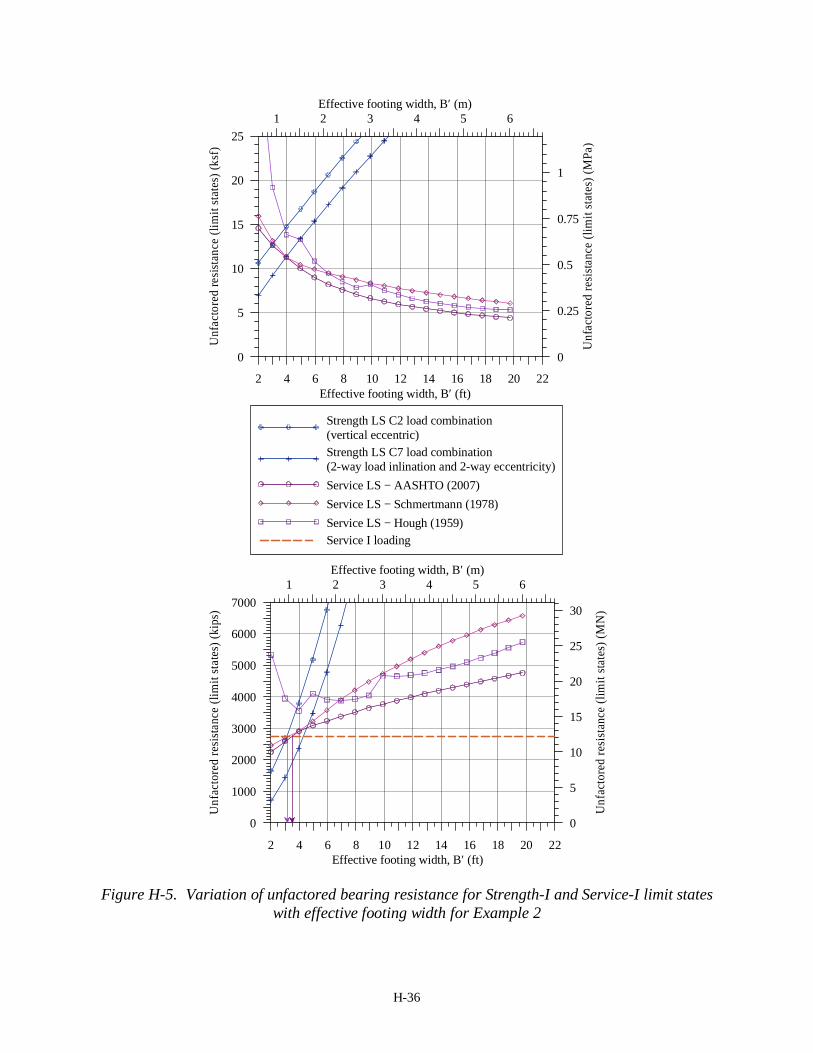
Figures H-5 and H-6 present the unfactored and factored bearing resistances for Strength-I loading, respectively, for different effective footing widths. The bearing load intensities (stresses) are plotted in the upper figures, whereas the lower ones present the bearing loads. The footing width refers to the effective width for both bearing capacity and settlement analyses. While the settlement analyses were carried out for the geometrical (full) foundation width, in the presentation of Figures H-5 and H-6, the width was transformed to be the effective width.
Applying the aforementioned corresponding vertical loads for the limit states in Figures H-5 and H-6, the following results are obtained: (a) for unfactored Service limit state (current AASHTO specifications), a footing width of 3.0ft (minimum admissible width) is required according to Hough (1959) method, 4.3ft is required according to Schmertmann (1978) method and 4.5ft is required according to AASHTO (2007) method, and (b) for factored Strength-I limit state, the minimum required footing width is 6.0ft when Strength-I C2 loading is considered, 8.9 ft when Strength-I C7 loading is considered. The recommended resistance factor in this study for Strength-I C7 loading is φ = 0.45, which corresponds to the current AASHTO (2007) specifications recommendation, thus the minimum footing width required as per the AASHTO(2007) specifications is also 8.9ft.
H-36
2 4 6 8 10 12 14 16 18 20 22Effective footing width, B′ (ft)
0
1000
2000
3000
4000
5000
6000
7000
Unf
acto
red
resi
stanc
e (li
mit
stat
es) (
kips
)
1 2 3 4 5 6Effective footing width, B′ (m)
0
5
10
15
20
25
30U
nfac
tore
d re
sist
ance
(lim
it sta
tes)
(MN
)
2 4 6 8 10 12 14 16 18 20 22Effective footing width, B′ (ft)
0
5
10
15
20
25
Unf
acto
red
resis
tanc
e (li
mit
stat
es) (
ksf)
1 2 3 4 5 6Effective footing width, B′ (m)
0
0.25
0.5
0.75
1
Unf
acto
red
resi
stanc
e (li
mit
stat
es) (
MPa
)
Strength LS C2 load combination(vertical eccentric)Strength LS C7 load combination(2-way load inlination and 2-way eccentricity)Service LS − AASHTO (2007)Service LS − Schmertmann (1978)Service LS − Hough (1959)Service I loading
Figure H-5. Variation of unfactored bearing resistance for Strength-I and Service-I limit states
with effective footing width for Example 2

H-37
2 4 6 8 10 12 14 16 18 20 22Effective footing width, B′ (ft)
0
1000
2000
3000
4000
5000
Fact
ored
ulti
mat
e lim
it st
ate
and
unfa
ctor
ed se
rvic
e lim
it st
ate
(kip
s)
1 2 3 4 5 6Effective footing width, B′ (m)
0
5
10
15
20
Fact
ored
ulti
mat
e lim
it st
ate
and
unfa
ctor
ed se
rvic
e lim
it st
ate
(MN
)
2 4 6 8 10 12 14 16 18 20 22Effective footing width, B′ (ft)
0
5
10
15
20
25
Fact
ored
ulti
mat
e lim
it st
ate
and
unfa
ctor
ed se
rvic
e lim
it st
ate
(ksf
)
1 2 3 4 5 6Effective footing width, B′ (m)
0
0.25
0.5
0.75
1
Fact
ored
ulti
mat
e lim
it st
ate
and
unfa
ctor
ed se
rvic
e lim
it st
ate
(MPa
)
Strength LS, C2 load − φ = 0.70Strength LS, C7 load − φ = 0.45Strength LS − φ = 0.45 (AASHTO, 2007)Service LS − AASHTO (2007)Service LS − Schmertmann (1978)Service LS − Hough (1959)Service I loadingStrength I, C2 loadingStrength I, C7 loading
Figure H-6 Variation of factored bearing resistance for Strength-I and unfactored resistance
for Service-I limit state with effective footing width for Example 2

H-38
The conclusions possible from Figures H-5 and H-6 are therefore:
1. Based on the strength limit state alone; the following foundation sizes (full geometric) are sufficient: • Strength limit state φ = 0.45: 8.9ft×52.4 ft • Strength limit state φ = 0.70: 6.0ft×52.4 ft
2. Based on the unfactored serviceability limit state (current AASHTO): a footing size of 4.5ft×52.4ft is required.
It can be noted that the Strength (C7) limit state determines the design in this design example. H.2.8 Sliding Resistance
The interfacial friction angle between the footing base and the gravel borrow fill is given as δs = 29.7° in the geotechnical report. This interfacial friction angle is conservative compared to the one recommended in this study. For φf = 38°, the interfacial friction angle obtained from the recommended relation is
tan(δs) = 0.91 tan(38) ⇒ δs = 35.4° But here, nominal sliding resistance has been calculated as follows:
F2τ = F1 × tan(δs) = F1 × tan(29.7) The minimum factored vertical load shown in Table H-15.2 for the designed footing width for
Strength-I and Service-I load against sliding is 2620.3kips (Service-I C5), for which the maximum lateral load is 24.6kips. Though in the case of the central pier no lateral force is caused by the earth pressure, the recommended resistance factors is taken as the minimum of the recommended in this study for cast in-situ footings, i.e. φτ = 0.40. Hence,
Factored sliding resistance, φτF2τ = 0.40 × 2620.3×tan(29.7) = 597.8kips > 24.6kips
The designed footing is safe in sliding for the Service-I C5 loading. For other load combinations, e.g. Strength-I C7, though the resultant lateral load is larger ( =(25.02+9.22)0.5 = 26.6kips), the vertical load is larger ( =2673.5kips) too. The factored sliding resistance for this vertical load is 610.0kips, which is much larger than the lateral load of 26.6kips. Therefore, the designed footing is safe in sliding. H.2.9 Discussions and Conclusions
It is seen from Figures H-5 and H-6 that the Strength limit states govern the footing dimension
in this design example. The Strength limit states are satisfied with a full geometric foundation width of 8.9ft (considering a maximum eccentricity of 0.50ft). The unfactored Service limit state requires a foundation width of at least 4.5ft. The footing widths for both of these limit states are smaller than the actually constructed footing, of width 13.1ft. This could be due to the difference in the settlement estimation methods used in the design reference and this study; the reference uses settlement estimation method described in Peck et al. (1974), which has not been used in this study.

H-39
H.3 EXAMPLE 3: BILLERICA BRIDGE, EAST ABUTMENT ON GRAVEL FILL H.3.1 Subsurface Condition
For general information regarding the Billerica Bridge, please refer to section 5.4.1. The subsurface at the east abutment location (based on boring GB-21) consists of 9inch of asphalt overlaying approximately 7.8ft of dense granular fill and then 4.0ft of very dense coarse sand and gravel overlaying a rock layer. The geotechnical report (URS, 2001) called for the replacement of the fill with gravel borrow material that would extend to the proposed footing elevation. As such, the foundation design follows the geotechnical report assuming the east abutment to be founded on the top of a compacted gravel layer, as for the central pier presented in Example 2. The parameters provided for the gravel borrow in the geotechnical report are: bulk unit weight γ (γ') = 120.0 pcf (63.65 pcf) (18.85/9.99 kN/m³), internal friction angle φf = 38° and interfacial friction angle between the footing base and the soil δs = 29.7°. The unit weight of the soil backfill of the abutment is taken as 124.9 pcf (19.6 kN/m³). The groundwater table is located at elevation 157.5 ft (48.0 m) and the foundation base is at elevation of 166.7ft (50.8m).
H.3.2 Loads, Load Combinations and Limit States
The load components as given in the reference are summarized in Table H-19. The loads are provided in units of force per unit foundation length referring to the abutment length of 61.65ft (across the bridge). The dead load includes the weights of superstructure and abutment as well as the soil backfill. The investigated load combinations and the resultant characteristic loading as well as the eccentricity e2 (refer to Figure 120 of Chapter 5 for load notations and directions) for the different load combinations are summarized in Table H-20. The design load components required for the stability analysis, which are the factored characteristic loadings with load factors according to AASHTO Section 3 (2007) (presented in Tables H-4.1 and H-4.2), are summarized in Tables H-21.1 and H-21.2 for the bearing capacity and sliding strength limit states, respectively. Only Service-I and Strength-I limit states have been used here for the determination of the design footing width. Due to the large magnitude of earth pressures at the abutment, the lateral loads and the eccentricities are markedly higher than those presented in the central pier analysis in example 2.
TABLE H-19. Loading at footing base for Example 3
Load at footing base F1
kip/ft (kN/m) F2
kip/ft (kN/m) M3
kip-ft/ft (kNm/m) dead load (DL) 35.80 (522.36) 0.0 -37.16 (-165.32) live load (LL) 4.40 (64.23) 1.61 (23.56) 23.24 (103.38) earth pressure (E) 0.0 9.61 (140.20) 90.14 (400.97) wind on structure (W) 0.0 0.19 (2.73) 3.25 (14.44) wind on live load (WL) 0.0 0.04 (0.61) 0.73 (3.23) lateral force (LF) 0.0 0.13 (1.94) 2.31 (10.26) temperature effects (RST) 0.0 0.59 (8.64) 10.28 (45.71) earthquake (EQ) 0.0 3.97 (57.87) 68.82 (306.13)

H-40
TABLE H-20. Load combinations and resultant characteristic (unfactored) loading for Example 3
Load
combi-nations
Load components F1
kips/ft (kN/m)
F2 kips/ft (kN/m)
M3 kips-ft/ft (kNm/m)
F2/F1 e2 = M3/F1
ft (m)
C1 DL + LL + E 40.2 (586.6)
11.2 (163.8)
76.2 (339.0) 0.279
1.896 (0.578)
C2 DL + E + W 35.8 (522.4)
9.8 (142.9)
56.2 (250.1) 0.274
1.571 (0.479)
C3 DL + LL + E + W + WL + LF
40.2 (586.6)
11.6 (169.0)
82.5 (367.0) 0.288
2.053 (0.626)
C4 DL + LL + E + RST 40.2 (586.59)
11.8 (172.4)
86.5 (384.7) 0.294
2.152 (0.656)
C5 DL + E + W + RST 35.8 (522.4)
10.4 (151.6)
66.5 (295.8) 0.290
1.856 (0.566)
C6 DL + LL + E + W + WL + LF + RST
40.2 (586.6)
12.2 (177.7)
92.8 (412.7) 0.303
2.309 (0.704)
C7 DL + LL + E + EQ 40.2 (586.6)
20.8 (304.0)
145.0 (645.2) 0.518
3.608 (1.100)
TABLE H-21.1. Load combinations and resultant design (factored) loading for bearing resistance
Limit state
load combinations
F1 kip/ft (kN/m)
F2 kip/ft (kN/m)
M3 kip-ft/ft (kNm/m)
Service-I C1 40.2 (586.6) 11.2 (163.8) 76.2 (339.0) Service-I C2 35.8 (522.4) 9.7 (141.0) 53.9 (240.0) Service-I C3 40.2 (586.6) 11.5 (167.1) 80.2 (356.9) Service-I C4 40.2 (586.6) 11.9 (174.1) 88.5 (393.9) Service-I C5 35.8 (522.4) 10.4 (151.4) 66.3 (294.8) Service-I C6 40.2 (586.6) 12.2 (177.5) 92.6 (411.7) Strength-I C1 52.5 (765.4) 17.2 (251.5) 129.4 (575.7) Strength-I C4 52.5 (765.4) 17.9 (261.9) 141.8 (630.6) Strength-V C2 50.7 (739.7) 16.9 (246.4) 125.3 (557.2) Strength-V C3 50.7 (739.7) 16.6 (242.1) 120.1 (534.4) Strength-V C5 44.8 (653.0) 15.2 (221.8) 102.4 (455.4) Strength-V C6 50.7 (739.7) 17.6 (256.8) 137.6 (612.1) Extreme-I C7 49.2 (717.2) 20.0 (291.7) 180.8 (804.3)
γEQ = 1.0

H-41
TABLE H-21.2. Load combinations and resultant design (factored) loading for sliding resistance
Limit state
load combinations
F1 kip/ft (kN/m)
F2 kip/ft (kN/m)
M3 kip-ft/ft (kNm/m)
Service-I C1 40.2 (586.6) 11.2 (163.8) 76.2 (339.0) Service-I C2 35.8 (522.4) 9.7 (141.0) 53.9 (240.0) Service-I C3 40.2 (586.6) 11.5 (167.1) 80.2 (356.9) Service-I C4 40.2 (586.6) 11.9 (174.1) 88.5 (393.9) Service-I C5 35.8 (522.4) 10.4 (151.4) 66.3 (294.8) Service-I C6 40.2 (586.6) 12.2 (177.5) 92.6 (411.7) Strength-I C1 39.9 (582.5) 17.2 (251.5) 142.4 (633.6) Strength-I C4 39.9 (582.5) 17.9 (261.9) 154.8 (688.4) Strength-V C2 38.2 (556.8) 16.9 (246.4) 138.3 (615.1) Strength-V C3 38.2 (556.8) 16.6 (242.1) 133.1 (592.2) Strength-V C5 32.2 (470.1) 15.2 (221.8) 115.4 (513.3) Strength-V C6 38.2 (556.8) 17.6 (256.8) 150.6 (669.9) Extreme-I C7 36.6 (534.4) 20.0 (291.7) 193.8 (862.2)
H.3.3 Nominal and Allowable Bearing Resistances at the Limit States
The bearing resistances of rectangular footings with widths of 2.95ft to 20.70ft, with the footing length kept fixed at 61.65ft according to the length of the abutment, have been calculated for Strength-I C4 limit state, according to AASHTO (2007) equation 10.6.3.1.2 with embedment depth equal to zero (note: the results are presented in the following sections as effective widths). The allowable bearing resistance for a Service-I limit state for a settlement of 1.5inches has been obtained using the AASHTO (2007) settlement calculation method (equation 10.6.2.4.2-1), Schmertmann (1978) and Hough (1959) settlement calculation methods.
From Table H-20, the Strength-I C4 loading on the footing produces one-way eccentricity of e2 = 2.15ft along the footing width along with one-way inclination. Hence for an example footing width of, say, B = 4.9ft, the effective footing width is B′= 4.9 − 2×2.15 = 0.6ft.
The footing for the abutment is placed on a gravel borrow fill compacted to result in an internal friction of 38°. The recommended resistance factor for Strength-I C4 load in/on controlled soil condition with soil of φf = 38° is φ = 0.45, which coincides with that recommended in AASHTO (2007) specifications. No resistance factors exist in the current specifications for the service limit state, hence, the estimated load required to produce a settlement of 1.5in has been left unfactored. H.3.4 Design Footing Width
The maximum load eccentricity corresponding to Strength-I loading is 2.15ft, produced by C4 load combination, whereas, for Service-I loading is 2.31ft produced by C6 load combination, along the footing width in both limit states, according to Table H-20. Hence, the minimum foundation width required for the limiting eccentricity is B = 13.86ft (=2.31ft×6). The maximum

H-42
vertical factored load for Strength-I limit state (bearing resistance; Table H-21.1) is 52.5kip/ft and the vertical unfactored load for Service-I limit state is 40.2kips/ft.
Figures H-7 and H-8 present the unfactored and factored bearing resistances for different effective footing widths. The bearing load intensities (stresses) are plotted in the upper figures, whereas the lower ones present the bearing loads per unit length of the foundation to be compatible with the load representation. The footing width refers to the effective width for both bearing capacity and settlement analyses. While the settlement analyses were carried out for the geometrical (full) foundation width, in the presentation of Figures H-7 and H-8, the width was transformed to be the effective width.
Figure H-7 shows the variation of unfactored bearing capacities with effective footing width for different Strength limit states as well as Service limit state estimated using AASHTO (2007) method. It can be seen that the unfactored load combination C7, which is related to the Extreme-I event (Tables H-20 and H-21.1), is the dominant load combination for design. But the current discussions are limited to the Strength-I limit state load combinations, namely C1 and C4, since the resistance factors have been developed only for the Strength-I limit states. Figure H-8 shows the variation of factored bearing capacities with effective footing width for Service-I and Strength-I (C4) loadings.
Applying the aforementioned vertical loads for the corresponding limit states in Figure H-8, the following results are obtained: (a) the minimum footing width required for Strength-I loading is 15.44ft when the recommended resistance factor of φ = 0.45 is applied, and (b) the minimum effective width required for Service-I LS, can be taken as the minimum admissible footing width for the limiting eccentricity corresponding to a full width 13.86ft (which corresponds to B' = 9.25ft in Figures H-7 and H-8).
The conclusions possible from Figures H-7 and H-8 are therefore:
1. Based on strength limit state alone, the following foundation size (full geometry) is sufficient: a. Strength limit state φ = 0.45: 15.5 ft×61.65 ft
2. Based on unfactored serviceability limit state (current AASHTO), all admissible footings for limiting eccentricity are safe: 13.9ft×61.65 ft

H-43
4 6 8 10 12 14 16 18 20Effective footing width, B′ (ft)
0
25
50
75
100
125
150
Unf
acto
red
resi
stan
ce (l
imit
stat
es) (
kip/
ft)
1.5 2.5 3.5 4.5 5.5Effective footing width, B′ (m)
0
1000
2000
Unf
acto
red
resi
stan
ce (l
imit
stat
es) (
kN/m
)
4 6 8 10 12 14 16 18 20Effective footing width, B′ (ft)
0
2
4
6
8
10
12
Unf
acto
red
resi
stan
ce (l
imit
stat
es) (
ksf)
1.5 2.5 3.5 4.5 5.5Effective footing width, B′ (m)
0
100
200
300
400
500
Unf
acto
red
resi
stan
ce (l
imit
stat
es) (
kPa)
(1-way load inlination and 1-way eccentricity)Strength LS - Load combination Strength-I (C4)Strength LS - Load combination Strength-V (C6)Strength LS - Load combination Extreme-I (C7)Service LS − AASHTO (2007)Service LS − Schmertmann et al (1978)Service LS − Hough (1959)Service I loading
Figure H-7. Variation of unfactored bearing resistance for Strength and Service-I limit states with effective footing width for Example 3; loads are expressed per unit length of the foundation
(L = 61.65ft)

H-44
4 6 8 10 12 14 16 18 20Effective footing width, B′ (ft)
0
2
4
6
8
10
12
Fact
ored
ulti
mat
e lim
it st
ate
and
unfa
ctro
ed se
rvic
e lim
it st
ate
(ksf
)
1.5 2.5 3.5 4.5 5.5Effective footing width, B′ (m)
0
100
200
300
400
500
Fact
ored
ulti
mat
e lim
it st
ate
and
unfa
ctor
ed s
ervi
ce li
mit
stat
e (k
Pa)
Strength I LS − φ = 0.45 (Recom)Strength I LS − φ = 0.45 (AASHTO, 2007)Service LS − AASHTO (2007)Service LS − Schmertmann (1978)Service LS − Hough (1959)Strength I loadingService I loading
4 6 8 10 12 14 16 18 20Effective footing width, B′ (ft)
0
25
50
75
100
125
150
Fact
ored
ulti
mat
e lim
it st
ate
and
unfa
ctor
ed s
ervi
ce li
mit
stat
e (k
ip/ft
)
1.5 2.5 3.5 4.5 5.5Effective footing width, B′ (m)
0
500
1000
1500
2000Fa
ctor
ed u
ltim
ate
limit
stat
e an
dun
fact
ored
ser
vice
lim
it st
ate
(kN
/m)
Figure H-8. Variation of factored bearing resistance for Strength-I C4 loading combination and unfactored Service-I limit states with effective footing width for Example 3; loads are
expressed per unit length of the foundation (L = 61.65ft)

H-45
H.3.5 Sliding Resistance
The interfacial friction angle between the footing base and the gravel borrow fill is given as δs = 29.7° in the geotechnical report. This interfacial friction angle is conservative compared to the one recommended in this study. For φf = 38°, the interfacial friction angle obtained from the recommended relation in this study is as follows, which has been used only for the purpose of comparison:
tan(δs) = 0.91 tan(38) ⇒ δs = 35.4° The recommended resistance factor for cast in-situ footings when at-rest earth pressure is
acting is φτ = 0.40 and that when active earth pressure is acting is φτ = 0.45. The current AASHTO (2007) specification recommends φτ = 0.80. Here, the lateral earth load considered during the design process is related to the at-rest earth pressure. For the back-fill with soil friction angle φf = 38°, the ratio of the lateral active earth pressure coefficient to the lateral at-rest earth pressure coefficient, Ka / K0 = 1 / (1 + sin φf ) = 1/1.616, assuming Rankine’s active earth pressure and at-rest earth pressure for normally consolidated cohessionless sand.
For the designed footing, the minimum factored vertical load and the corresponding lateral loads under Strength-I and Service-I loadings, thereby, the factored sliding resistance in each case are as follows. Service-I LS:
At-rest earth pressure: The minimum vertical load = 35.8kips/ft, and the corresponding maximum lateral
load = 10.4kips/ft (Table H-21.2) δs = 29.7°: φτF2τ = 0.40 × 35.8×tan(29.7) = 8.2kips/ft < 10.4kips/ft δs = 35.4°: φτF2τ = 0.40 × 35.8×tan(35.4) = 10.2kips/ft < 10.4kips/ft Active earth pressure:
The corresponding lateral load involving active earth pressure is (Tables H-19 and H-21.2)
2110.4 9.61 9.61 6.74kips/ft
1.616EaF = − + × =
.
δs = 29.7°: φτF2Ea = 0.45 × 35.8×tan(29.7) = 9.2kips/ft > 6.74kips/ft δs = 35.4°: φτF2Ea = 0.45 × 35.8×tan(35.4) = 11.4kips/ft > 6.74kips/ft Current AASHTO: δs = 29.7°: φτF2τ = 0.80 × 35.8×tan(29.7) = 16.3kips/ft > 10.4kips/ft δs = 35.4°: φτF2τ = 0.80 × 35.8×tan(35.4) = 20.4kips/ft > 10.4kips/ft
Strength I LS:
At-rest earth pressure: The minimum vertical load = 39.9kips/ft, and the corresponding maximum lateral
load = 17.9kips/ft (Table H-21.2) δs = 29.7°: φτF2τ = 0.40 ×39.9×tan(29.7) = 9.10kips/ft < 17.9kips/ft δs = 35.4°: φτF2τ = 0.40 ×39.9×tan(35.4) = 11.34kips/ft < 17.9kips/ft
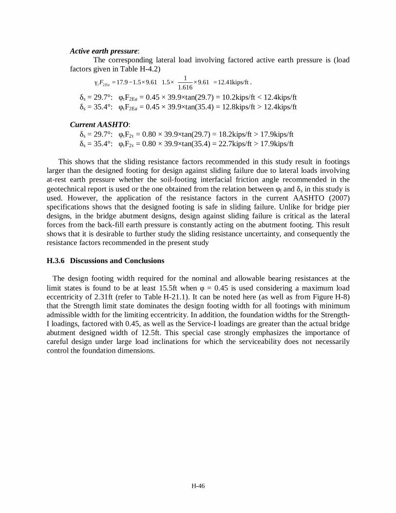
H-46
Active earth pressure: The corresponding lateral load involving factored active earth pressure is (load
factors given in Table H-4.2)
2117.9 1.5 9.61 1.5 9.61 12.41kips/ft
1.616i EaF γ = − × + × × =
.
δs = 29.7°: φτF2Ea = 0.45 × 39.9×tan(29.7) = 10.2kips/ft < 12.4kips/ft δs = 35.4°: φτF2Ea = 0.45 × 39.9×tan(35.4) = 12.8kips/ft > 12.4kips/ft Current AASHTO: δs = 29.7°: φτF2τ = 0.80 × 39.9×tan(29.7) = 18.2kips/ft > 17.9kips/ft δs = 35.4°: φτF2τ = 0.80 × 39.9×tan(35.4) = 22.7kips/ft > 17.9kips/ft
This shows that the sliding resistance factors recommended in this study result in footings
larger than the designed footing for design against sliding failure due to lateral loads involving at-rest earth pressure whether the soil-footing interfacial friction angle recommended in the geotechnical report is used or the one obtained from the relation between φf and δs in this study is used. However, the application of the resistance factors in the current AASHTO (2007) specifications shows that the designed footing is safe in sliding failure. Unlike for bridge pier designs, in the bridge abutment designs, design against sliding failure is critical as the lateral forces from the back-fill earth pressure is constantly acting on the abutment footing. This result shows that it is desirable to further study the sliding resistance uncertainty, and consequently the resistance factors recommended in the present study
H.3.6 Discussions and Conclusions
The design footing width required for the nominal and allowable bearing resistances at the
limit states is found to be at least 15.5ft when φ = 0.45 is used considering a maximum load eccentricity of 2.31ft (refer to Table H-21.1). It can be noted here (as well as from Figure H-8) that the Strength limit state dominates the design footing width for all footings with minimum admissible width for the limiting eccentricity. In addition, the foundation widths for the Strength-I loadings, factored with 0.45, as well as the Service-I loadings are greater than the actual bridge abutment designed width of 12.5ft. This special case strongly emphasizes the importance of careful design under large load inclinations for which the serviceability does not necessarily control the foundation dimensions.

H-47
H.4 EXAMPLE 4: INTEGRAL BRIDGE ABUTMENT ON STRUCTURAL FILL – GEC6–EXAMPLE 2
H.4.1 Subsurface Conditions
The subsurface conditions and the abutment geometry given in Example B2 of FHWA Geotechnical Engineering Circular No. 6 (GEC6), Appendix B (Kimmerling, 2002) is shown in Figure H-9, and the soil parameters are summarized in Table H-22. The groundwater table is located at 42.0 ft (12.81 m) below the surface of the proposed bridge approach elevation. The abutment is placed on structural fill of well graded silty sand and gravel that is 15.0ft (4.57m) deep below the footing base. The fill forms a slope with a grade of 2H:1V at a distance of 1.5 times the width of the proposed footing from the slope.
The soil friction angles are calculated using the correlation with SPT blow counts proposed by Peck, Hanson and Thornburn (PHT) as modified by Kulhawy and Mayne (1990). This calculation of the soil friction angle is compatible with the methodology used in developing the resistance factors. The footing is poured on site, hence, the base friction angle δs is assumed to be equal to the soil friction angle φf .
Figure H-9 Geometry and soil conditions of integral bridge abutment – Example 4 (1m ≈ 3.3ft)
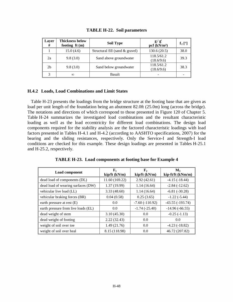
H-48
TABLE H-22. Soil parameters
Layer #
Thickness below footing ft (m) Soil Type γ / γ'
pcf (kN/m³) φf [°]
1 15.0 (4.6) Structural fill (sand & gravel) 130.6 (20.5) 38.0
2a 9.8 (3.0) Sand above groundwater 118.5/61.2 (18.6/9.6) 39.3
2b 9.8 (3.0) Sand below groundwater 118.5/61.2 (18.6/9.6) 38.3
3 ∞ Basalt - -
H.4.2 Loads, Load Combinations and Limit States Table H-23 presents the loadings from the bridge structure at the footing base that are given as
load per unit length of the foundation being an abutment 82.0ft (25.0m) long (across the bridge). The notations and directions of which correspond to those presented in Figure 120 of Chapter 5. Table H-24 summarizes the investigated load combinations and the resultant characteristic loading as well as the load eccentricity for different load combinations. The design load components required for the stability analysis are the factored characteristic loadings with load factors presented in Tables H-4.1 and H-4.2 (according to AASHTO specifications, 2007) for the bearing and the sliding resistances, respectively. Only the Service-I and Strength-I load conditions are checked for this example. These design loadings are presented in Tables H-25.1 and H-25.2, respectively.
TABLE H-23. Load components at footing base for Example 4
Load component F1
kip/ft (kN/m) F2
kip/ft (kN/m) M3
kip-ft/ft (kNm/m) dead load of components (DL) 11.60 (169.22) 2.92 (42.61) -4.15 (-18.44) dead load of wearing surfaces (DW) 1.37 (19.99) 1.14 (16.64) -2.84 (-12.62) vehicular live load (LL) 3.33 (48.60) 1.14 (16.64) -6.81 (-30.28) vehicular braking forces (BR) 0.04 (0.58) 0.25 (3.65) -1.22 (-5.44) earth pressure at rest (E) 0.0 -7.60 (-110.92) -43.55 (-193.74) earth pressure from live loads (EL) 0.0 -1.74 (-25.40) -14.96 (-66.55) dead weight of stem 3.10 (45.30) 0.0 -0.25 (-1.13) dead weight of footing 2.22 (32.43) 0.0 0.0 weight of soil over toe 1.49 (21.76) 0.0 -4.23 (-18.82) weight of soil over heal 8.15 (118.98) 0.0 46.72 (207.82)

H-49
TABLE H-24. Load combinations and resultant characteristic (unfactored) loading
Load combinations Load components
F1 kip/ft
(kN/m)
F2 kip/ft
(kN/m)
Mcenter kip-ft/ft
(kNm/m) F2/F1
e2 = M3/F1 ft (m)
C1 EG+DL+DW+E +LL+EL+BR
31.3 (456.9)
3.5 (50.5)
31.3 (139.2) 0.111 1.000
(0.305)
C2 EG+DL+DW+E 27.9 (407.7)
3.5 (51.7)
8.3 (36.9) 0.127 0.298
(0.091)
TABLE H-25.1. Load combinations and resultant design (factored) loading
for bearing resistance
Limit state load combinations F1 kip/ft (kN/m)
F2 kip/ft (kN/m)
M3 kip-ft/ft (kNm/m)
Service-I C1 31.3 (456.9) 3.5 (50.5) 31.3 (139.2)
Strength-I C1 41.2 (600.67) 5.9 (86.13) 62.2 (276.74)
Strength-I C2 35.3 (514.61) 6.0 (88.16) 63.8 (283.65)
TABLE H-25.2. Load combinations and resultant design (factored) loading
for sliding resistance
Limit state load combinations F1 kip/ft (kN/m)
F2 kip/ft (kN/m)
M3 kip-ft/ft (kNm/m)
Service-I C1 31.3 (456.9) 3.5 (50.5) 31.3 (139.2)
Strength-I C1 30.7 (448.0) 7.9 (115.2) 73.1 (325.3)
Strength-I C2 24.8 (361.9) 8.0 (117.2) 40.4 (179.5)
γEQ assumed to be 0.0 in this example
H.4.3 Nominal and Allowable Bearing Resistances at the Limit States The bearing resistances of rectangular footings with widths of 2.95 ft to 20.70 ft have been
calculated for Strength-I limit states (C1 and C2 loads) as well as for the Service-I limit state taking an embedment depth equal to 4.5ft (note: the results are presented in the following sections as effective width). The footing length corresponds to the fixed length of the abutment and is kept fixed at 82.0 ft. The bearing resistances have been calculated according to Figure 10.6.3.1.2c-2 of AASHTO (2007) (Section 10) to account for the effect of the slope. The allowable bearing resistance for a Service-I limit state of allowable settlement of 1.5inches has been obtained using the AASHTO (2007) settlement calculation method (equation 10.6.2.4.2-1), Schmertmann (1978) and Hough (1959) settlement calculation methods.
The footing for the abutment is placed on a structural fill, which is to be compacted to result in an internal friction of 38°. The resulting average soil friction angle to the depth of influence for

H-50
different footing sizes are obtained as within 38±0.5°, or 38°. Hence, the recommended resistance factor for the Strength-I loads (both C1 and C2 produce one-way inclined and one-way-eccentric loading) in/on controlled soil condition is taken as φ = 0.45 for positive eccentricity for soil of φf = 38°. This resistance factor coincides with that recommended in AASHTO (2007) specifications. No resistance factors exist in the current specifications for the service limit state, hence, the estimated load required to produce a settlement of 1.5in has been left unfactored.
H.4.4 Design Footing Width
From Table H-24, it can be seen that the maximum load eccentricity along the footing width is
1.0ft produced by the C1 load combination. Hence, the minimum foundation width admissible by the limiting eccentricity to B/6 is B = 6.0ft (=1.0ft×6). The maximum vertical Strength-I loading is 41.2kips/ft while the maximum Service-I loading is 31.3kips/ft (Table H-25.1).
Figures H-10 and H-11 present the unfactored and factored bearing resistances for different effective footing widths. The bearing load intensities (stresses) are plotted in the upper figures, whereas the lower ones present the bearing loads per unit length of the foundation to be compatible with the load presentation. The footing width refers to the effective width for both bearing capacity and settlement analyses. While the settlement analyses were carried out for the geometrical (full) foundation width, in the presentation of Figures H-10 and H-11, the width was transformed to be the effective width.
Figure H-10 shows the variation of the unfactored bearing capacities with effective footing width for different Strength limit states as well as the Service limit states estimated. The unfactored load combination C1 causes a larger load eccentricity and lower load inclination, while C2 causes a higher load inclination but a smaller load eccentricity with a smaller vertical load component (Table H-24). From the figure, it is seen that the difference of the bearing resistances for both these load combinations is, however, very small. Hence, Strength-I C1, which has higher vertical loading, has been considered. Figure H-11 shows the variation of factored bearing capacities with effective footing width for Service-I and Strength-I C1 loadings.
Applying the aforementioned vertical loads for the corresponding limit states in Figure H-11, the following results are obtained: all footing widths larger than the minimum admissible width satisfy the Strength-I as well as the Service-I load requirements.
The conclusions possible from Figures H-10 and H-11 are therefore:
1. Based on strength limit state alone, the following foundation size (full geometry) is sufficient: Strength limit state φ = 0.45: 6.0ft×82.0 ft
2. Based on the unfactored service limit state (current AASHTO) also, all the footing sizes admissible by limiting eccentricity are safe: 6.0 ft×82.0 ft
These footing widths are smaller than the designed width of 9.84ft in GEC6, which uses Hough
(1959) method for the settlement calculation. This discrepancy can arise due to the way the soil parameters are evaluated and considered settlement estimation.
For comparison, when the limiting eccentricity of B/4 is taken instead of B/6 used here, the minimum admissible footing dimension is 4.0ft×82.0ft. Then referring to Figure H-11, the minimum admissible footing size still governs the footing design. Hence, the choice of the limiting eccentricity totally governs the design in this example.

H-51
2 4 6 8 10 12 14 16 18 20Effective footing width, B′ (ft)
0
25
50
75
100
125
150
175
200
Unf
acto
red
resi
stan
ce (l
imit
state
s) (k
ip/ft
)
1 2 3 4 5 6Effective footing width, B′ (m)
0
500
1000
1500
2000
2500
Unf
acto
red
resi
stanc
e (li
mit
stat
es) (
kN/m
)
2 4 6 8 10 12 14 16 18 20Effective footing width, B′ (ft)
0
10
20
30
40
Unf
acto
red
resis
tanc
e (li
mit
stat
es) (
ksf)
1 2 3 4 5 6Effective footing width, B′ (m)
0
400
800
1200
1600
Unf
acto
red
resi
stanc
e (li
mit
state
s) (k
Pa)
(1-way load inlination and 1-way eccentricity)Strength LS - Load combination C1Strength LS - Load combination C2Service LS − AASHTO (2007)Service LS − Schmertmann et al (1978)Service LS − Hough (1959)Service I loading
Figure H-10. Variation of unfactored bearing resistance for Strength-I and Service-I limit states with effective footing width for Example 4.

H-52
2 4 6 8 10 12 14 16 18 20Effective footing width, B′ (ft)
0
25
50
75
100
125
Fact
ored
ulti
mat
e lim
it st
ate
and
unfa
ctor
ed se
rvic
e lim
it st
ate
(kip
/ft)
1 2 3 4 5 6Effective footing width, B′ (m)
0
400
800
1200
1600
Fact
ored
ulti
mat
e lim
it st
ate
and
unfa
ctor
ed se
rvic
e lim
it sta
te (k
N/m
)
2 4 6 8 10 12 14 16 18 20Effective footing width, B′ (ft)
0
5
10
15
20
25
Fact
ored
ulti
mat
e lim
it sta
te a
ndun
fact
ored
serv
ice
limit
state
(ksf
)
1 2 3 4 5 6Effective footing width, B′ (m)
0
200
400
600
800
1000
Fact
ored
ulti
mat
e lim
it sta
te a
ndun
fact
ored
serv
ice
limit
stat
e (k
Pa)
Strength I LS − φ = 0.45 (Recom)Strength I LS − φ = 0.45 (AASHTO, 2007)Service LS − AASHTO (2007)Service LS − Schmertmann et al (1978)Service LS − Hough (1959)Strength I loadingService I loading
Figure H-11. Variation of factored bearing resistance for Strength-I C1 and unfactored Service-I limit states with effective footing width for Example 4.

H-53
H.4.5 Sliding Resistance
The footing is poured on site; the recommended resistance factor for cast in-place footings
when at-rest earth pressure is acting is φτ = 0.40 and that when active earth pressure is acting is φτ = 0.45, while the current AASHTO (2007) specification recommends φτ = 0.80.
Here, the lateral earth load considered during the design process is related to the at-rest earth pressure. For the back-fill with soil friction angle φf = 38°, the ratio of the lateral active earth pressure coefficient to the lateral at-rest earth pressure coefficient, Ka / K0 = 1/(1 + sin φf ) = 1/1.616, assuming Rankine’s active earth pressure and at-rest earth pressure for normally consolidated cohessionless sand. Also, for φf = 38°, the interfacial friction angle obtained from the recommended relation in this study is as follows:
tan(δs) = 0.91 tan(38) ⇒ δs = 35.4° For the designed footing, the minimum factored vertical load and the corresponding lateral
loads under Strength-I and Service-I loadings, thereby, the factored sliding resistance in each case are as follows. Service-I LS:
At-rest earth pressure: The minimum vertical load = 31.3kips/ft and the corresponding maximum total
lateral load = 3.5kips/ft (Table H-25.2) when at-rest earth pressure is acting. Hence, Factored sliding resistance φτF2E0 = 0.40 × 31.3×tan(35.4) = 8.90kips/ft > 3.5kips/ft Active earth pressure:
The corresponding lateral load involving active earth pressure is (Tables H-23 and H-25.2)
213.5 ( 7.60) ( 7.60) 6.40kips/ft
1.616EaF = − − + × − =
.
Factored sliding resistance φτF2Ea = 0.45 × 31.3×tan(35.4) = 10.01kips/ft > 6.40kips/ft Current AASHTO: Factored sliding resistance φτF2τ = 0.80 × 31.3×tan(35.4)
= 17.8kips/ft > 3.5kips/ft > 6.40kips/ft Strength I LS:
At-rest earth pressure: The minimum vertical load = 30.7kips/ft, and the corresponding maximum lateral
load = 7.9kips/ft (Table H-25.2) when active earth pressure is acting. Hence, Factored sliding resistance φτF2E0 = 0.40 × 30.7×tan(35.4) = 8.73kips/ft > 7.9kips/ft Active earth pressure:
The corresponding lateral load involving active earth pressure is (Tables H-23 and H-25.2)
217.9 1.5 ( 7.60) 1.5 ( 7.60) 12.25kips/ft
1.616EaF = − × − + × × − =
.

H-54
Factored sliding resistance φτF2Ea = 0.45 × 30.7×tan(35.4) = 9.82kips/ft < 12.25kips/ft Current AASHTO: Factored sliding resistance φτF2τ = 0.80 × 30.7×tan(35.4)
= 17.45kips/ft > 7.9kips/ft > 12.25kips/ft
This shows that the sliding resistance factors recommended in this study result in footings larger than the designed footing for design against sliding failure due to lateral loads involving at-rest as well as active earth pressures, except when unfactored lateral active earth pressure is considered. Since the design of abutment footings against sliding is critical, further study on the application of the resistance factors for sliding is necessary. H.4.6 Discussions and Conclusions
The limiting eccentricity governs the footing design in the example. From Figures H-10 and H-
11 it is seen that for both the Strength-I and Service-I limit states, the footing dimension required is that of the minimum admissible size for limiting eccentricity. When the limiting eccentricity of B/6 is used, a footing of 6.0ft×82.0ft fulfills the requirements for Strength-I and Service-I limit states. When the limiting eccentricity of B/4 is used, a footing of 4.0ft×82.0ft fulfills the requirements for both the limit states. A footing of 6.0ft×82.0ft may be recommended for this example.

H-55
H.5 EXAMPLE 5: STUB SEAT-TYPE BRIDGE ABUTMENT ON STRUCTURAL FILL – GEC6-EXAMPLE 3
H.5.1 Subsurface Conditions
The subsurface conditions and the abutment geometry given in Example C2 of FHWA
Geotechnical Engineering Circular No. 6 (GEC6), Appendix C (Kimmerling, 2002) shown in Figure H-12, and the soil parameters are summarized in Table H-26. The groundwater table is located 51.9 ft (15.81 m) below the surface of the proposed bridge approach elevation. The abutment is placed on structural fill of well graded silty sand and gravel which is 15.0ft (4.57m) deep below the footing base. The fill forms a slope with a grade of 2H:1V at a distance of 1.5 times the width of the proposed footing from the slope.
The soil friction angles are calculated using the correlation with SPT blow counts proposed by Peck, Hanson and Thornburn (PHT) as modified by Kulhawy and Mayne (1990). As also mentioned in the Example 1 presented here, this calculation of soil friction angle is compatible with the methodology used in developing the resistance factors. The footing is poured on site, hence, the base friction angle δs is assumed to be equal to the soil friction angle φf .
Figure H-12. Geometry and soil conditions of stub seat-type abutment for Example 5 (1m≈3.3ft).

H-56
TABLE H-26. Soil parameters
Layer
# Thickness below
footing ft (m) Soil type γ psf (kN/m³) φf [°]
1 15.0 (4.6) Sand and Gravel (fill) 130.6 (20.50) 38.00 2 19.7 (6.0) Silt 110.2 (17.30) 30.11 3 19.7 (6.0) silty Sand below groundwater 124.9 (19.60) 31.54 4 ∞ Gravel, dense -
H.5.2 Loads, Load Components and Limit States The loadings from the bridge structure at the footing base are given for per unit length of the
foundation in Table H-27, the notations and directions of which correspond to those presented in Figure 120 of Chapter 5. The moment M3 refers to the moment at the center of the footing and counter-clockwise moments are taken positive. Table H-28 summarizes the investigated load combinations and the resultant characteristic loading as well as the load eccentricity for different load combinations. The design load components required for the stability analysis are the factored characteristic loadings with load factors presented in Tables H-4.1 and H-4.2 (according to AASHTO specifications, 2007) for the bearing and the sliding resistances, respectively. Only the Service-I and Strength-I load conditions are checked for this example. These design loadings are presented in Tables H-29.1 and H-29.2, respectively.
TABLE H-27. Loading at footing base
Load components F1
kip/ft (kN/m) F2
kip/ft (kN/m) M3
kip-ft/ft (kNm/m) dead load of components (DL) 14.35 (209.32) 0.00 -9.88 (-43.95) vehicular live load (LL) 4.22 (61.52) 0.00 -2.90 (-12.91) dead load on wearing surfaces (DW) 1.22 (17.84) 0.00 -0.84 (-3.74) shear loads from bearing pads (V) 0.00 2.87 (41.88) -30.50 (-135.68) active earth pressure from soil fill (E) 0.00 4.79 (69.86) -27.43 (-122.02) earth pressure from live loads (EL) 0.00 1.10 (16.00) -9.42 (-41.92) dead weight of stem (EG) 3.93 (57.29) 0.00 -1.61 (-7.16) dead weight of footing (EG) 2.37 (34.59) 0.00 0.00 weight of soil over toe (EG) Neglected weight of soil over heal (EG) 9.44 (137.72) 0.00 26.78 (119.13)

H-57
TABLE H-28. Load combinations and resultant characteristic (unfactored) loading
Load combinations Load components
F1 kip/ft
(kN/m)
F2 kip/ft
(kN/m)
M3 kip-ft/ft
(kNm/m) F2/F1
e2 =M3/F1 ft (m)
C1: EG+DL+DW+E 31.3 (456.8)
4.8 (69.9)
13.0 (57.8) 0.153 0.413
(0.126)
C2: EG+DL+DW+E+V 31.3 (456.8)
7.7 (111.7)
43.5 (193.4) 0.245 1.387
(0.423)
C3: EG+DL+DW+E+LL+EL 35.5 (518.3)
5.9 (85.9)
25.3 (112.6) 0.166 0.712
(0.217)
C4: EG+DL+DW+E+LL+EL+V 35.5 (518.3)
8.8 (127.7)
55.8 (248.3) 0.246 1.571
(0.479)
TABLE H-29.1. Load combinations and resultant design (factored) loading for bearing resistance
Load combinations F1
kip/ft (kN/m) F2
kip/ft (kN/m) M3
kip-ft/ft (kNm/m) Service-I C2 31.3 (456.8) 7.7 (111.7) 43.5 (193.4) Strength-I C1 39.4 (575.4) 7.2 (104.8) 23.3 (103.6) Strength-I C2 39.4 (575.4) 10.6 (155.0) 59.9 (266.4) Strength-V C3 42.9 (625.7) 9.1 (132.8) 51.2 (227.6) Strength-V C4 42.9 (625.7) 12.5 (183.0) 87.8 (390.4)
TABLE H-29.2. Load combinations and resultant design (factored) loading for sliding resistance
Load Combinations F1
kip/ft (kN/m) F2
kip/ft (kN/m) M3
kip-ft/ft (kNm/m) Service-I C2 31.3 (456.8) 7.7 (111.7) 43.5 (193.4) Strength-I C1 27.9 (406.6) 7.2 (104.8) 27.9 (124.2) Strength-I C2 27.9 (406.6) 10.6 (155.0) 64.5 (287.1) Strength-V C3 36.8 (537.2) 9.1 (132.8) 47.0 (209.0) Strength-V C4 36.8 (537.2) 12.5 (183.0) 83.6 (371.8)
H.5.3 Nominal and Allowable Bearing Resistances at Limit States The bearing resistances of rectangular footings with widths of 2.95 ft to 20.70 ft have been
calculated for Strength-I limit states for the C2 load combination, as well as for the Service-I limit state taking embedment depth equal to 4.5ft (note: the results are presented in the following sections as effective width). The footing length corresponds to the fixed length of the abutment and is kept fixed at 82.0 ft. The bearing resistances have been calculated according to Figure 10.6.3.1.2c-2 of AASHTO (2007) (Section 10) to account for the effect of the slope. The

H-58
allowable bearing resistance for a Service-I limit state of an allowable settlement of 1.5inches has been obtained using the AASHTO (2007) settlement calculation method (equation 10.6.2.4.2-1), Schmertmann (1978) and Hough (1959) settlement calculation methods
The footing for the abutment is placed on gravel borrow fill, filled to a shallow depth. Table H-30 shows the variation of average soil friction angle of the soil strata below footing base, along with whether the subsurface is considered controlled or natural soil condition and the recommended resistance factors for bearing resistance. The soil condition has been taken as natural, if less than 50% of the influence depth below the footing base is gravel borrow fill, i.e., more than 50% of this is natural strata. The recommended resistance factors considered thus vary according to the average friction angle as well as the soil condition for different footing width, which ranges from 0.45 for smaller footings and 0.35 for larger footings. The current AASHTO (2007) specification recommends the use of φ = 0.45 for all footing sizes. No resistance factors exist in the current specifications for the service limit state, hence, the estimated load required to produce a settlement of 1.5in has been left unfactored.
Table H-30 Variation of average φf and thereby the recommended resistance factors
according to the footing width for the given subsurface conditions
B (ft) Average φf (°)
Soil Condition*
Recommended φ B (ft) Average
φf (°) Soil
Condition* Recommended
φ
2.95 38.00 Controlled 0.45 12.80 35.18 Controlled 0.40 3.94 38.00 Controlled 0.45 13.78 34.86 Controlled 0.40 4.92 38.00 Controlled 0.45 14.76 34.58 Controlled 0.40 5.91 38.00 Controlled 0.45 15.75 34.33 Natural 0.35 6.89 38.00 Controlled 0.45 16.73 34.11 Natural 0.35 7.87 37.70 Controlled 0.45 17.72 33.94 Natural 0.35 8.86 37.02 Controlled 0.45 18.70 33.85 Natural 0.35 9.84 36.45 Controlled 0.40 19.68 33.77 Natural 0.35 10.83 35.96 Controlled 0.40 20.67 33.69 Natural 0.35 11.81 35.54 Controlled 0.40
* Soil condition taken as Natural when more than 50% of the subsurface strata within the influence depth below the footing base incorporates natural strata.
H.5.4 Design Footing Width
The largest load eccentricity caused by the load combinations related to Service-I and Strength-
I loads, according to the characteristic loadings listed in Table H-28, is 1.39 ft from C2 combination (C3 and C4 combinations are applicable to Strength-V only, so, not considered at present). Hence, the minimum admissible footing due to limited eccentricity is of width B = 8.35ft (=1.39ft×6) considering the limiting eccentricity as B/6. The maximum vertical loading in Strength-I is 39.4kips/ft while the maximum in Service-I is 31.3kips/ft.
Figures H-13 and H-14 present the unfactored and factored bearing resistances for different effective footing widths. The bearing load intensities (stresses) are plotted in the upper figures, whereas the lower ones present the bearing loads per unit length of the foundation to be compatible with the load presentation. The footing width refers to the effective width for both

H-59
bearing capacity and settlement analyses. While the settlement analyses were carried out for the geometrical (full) foundation width, in the presentation of Figures H-13 and H-14, the widths were transformed to be the effective widths.
Figure H-13 shows the variation of the unfactored bearing capacities with effective footing width for different Strength limit states as well as the Service limit state. The unfactored load combination C2 causes a larger load eccentricity as well as a larger load inclination compared to the combination C1 (Table H-28). Figure H-14 shows the variation of factored bearing capacities with effective footing width for Strength-I limit state for C2 load combination and unfactored Service-I limit state. It is to be noted that while the AASHTO (2007) method leads to lower allowable loads for 1.5inch settlement as the footing size increases, the allowable pressure (stress) decreases with the increase in the footing width. On the other hand, Schmertmann (1978) and Hough (1959) methods show an overall increase in the allowable pressures with an increase in the footing size. This difference is attributed by the fact that in AASHTO (2007) method the soil elastic modulus has been taken as the weighted average of all the soil strata to the influence depth from the footing base, whereas Schmertmann (1978) method estimate the settlement caused by each soil stratum using the average modulus for each stratum and Hough (1959) method uses bearing capacity index C′ based on empirical curves for different soil types.
Applying the aforementioned vertical loads for the corresponding limit states in Figure H-14, the following results are obtained: (a) the minimum footing width (full size) required for the Strength-I limit state is B = 6.4ft, which is smaller than the minimum admissible footing of width B = 8.35ft, and (b) the minimum effective footing widths required for Service-I loadings are smaller than 14.8ft when AASHO method of settlement estimation is used, while using Schmertmann (1978) and Hough (1959) methods result in a footing of minimum admissible width is sufficient.
The conclusions possible from Figures H-13 and H-14 are therefore:
1. Based on the strength limit state alone, the minimum admissible footing size (full geometry) is required: • Strength limit state φ = 0.45 to 0.35: 8.35ft×82.0 ft • Strength limit state φ = 0.45 (current AASHTO): 8.35ft×82.0 ft
2. Based on the unfactored serviceability limit state (current AASHTO): 8.35ft×82.0 ft is recommended
The footing dimensions obtained here for the factored service limit state provides a footing of a
smaller dimension compared to 10.5ft obtained in GEC6. The discrepancy in the widths can arise from the differences in the way different soil parameters are considered and the settlement calculation methods used.
Further, for comparison, when the limiting eccentricity of B/4 is taken instead of B/6 used here, the minimum admissible footing dimension is 5.6ft×82.0ft. In this case, the Strength-I limit state governs the design as the Service-I limit state requires the minimum admissible footing size. In this sense, the choice of the limiting eccentricity governs which limit state, either Strength-I or Service-I, dominates the footing design in this example.

H-60
2 4 6 8 10 12 14 16 18 20Effective footing width, B′ (ft)
0
25
50
75
100
125
Unf
acto
red
resi
stanc
e (li
mit
state
s) (k
ip/ft
)
1 2 3 4 5 6Effective footing width, B′ (m)
0
500
1000
1500
Unf
acto
red
resis
tanc
e (li
mit
stat
es) (
kN/m
)
2 4 6 8 10 12 14 16 18 20Effective footing width, B′ (ft)
0
5
10
15
20
25
30
Unf
acto
red
resis
tanc
e (li
mit
stat
es) (
ksf)
1 2 3 4 5 6Effective footing width, B′ (m)
0
200
400
600
800
1000
1200
1400
Unf
acto
red
resi
stanc
e (li
mit
stat
es) (
kPa)
(1-way load inlination and 1-way eccentricity)Strength LS - Load combination C1Strength LS - Load combination C2Service LS − AASHTO (2007)Service LS − Schmertmann (1978)Service LS − Hough (1959)Service I loading
Figure H-13. Variation of unfactored bearing resistance for Strength-I and Service-I limit states with effective footing width for Example 5.

H-61
2 4 6 8 10 12 14 16 18 20Effective footing width, B′ (ft)
0
4
8
12
Fact
ored
ulti
mat
e lim
it sta
te a
ndun
fact
ored
serv
ice
limit
stat
e (k
sf)
1 2 3 4 5 6Effective footing width, B′ (m)
0
100
200
300
400
500
Fact
ored
ulti
mat
e lim
it sta
te a
ndun
fact
ored
serv
ice
limit
stat
e (k
Pa)
Strength LS − φ = 0.35-0.45 (varying; Recom)Strength LS − φ = 0.45 (AASHTO, 2007)Service LS − AASHTO (2007)Service LS − Schmertmann (1978)Service LS − Hough (1959)Strength I loading (factored)Service I loading
2 4 6 8 10 12 14 16 18 20Effective footing width, B′ (ft)
0
25
50
75
Fact
ored
ulti
mat
e lim
it st
ate
and
unfa
ctor
ed se
rvic
e lim
it st
ate
(kip
/ft)
1 2 3 4 5 6Effective footing width, B′ (m)
0
200
400
600
800
1000
Fact
ored
ulti
mat
e lim
it st
ate
and
unfa
ctor
ed se
rvic
e lim
it st
ate
(kN
/m)
Figure H-14. Variation of factored bearing resistance for Strength-I C2 and unfactored Service-I limit states with effective footing width for Example 5.

H-62
H.5.5 Sliding Resistance The footing is cast in-place; the recommended resistance factor for cast in-place footings when
at-rest earth pressure is acting is φτ = 0.40 and that when active earth pressure is acting is φτ = 0.45, while the current AASHTO (2007) specification recommends φτ = 0.80.
Here, the lateral earth load considered during the design process is related to the active earth pressure. For the back-fill with soil friction angle φf = 38°, the ratio of the lateral at-rest earth pressure coefficient to the lateral active earth pressure coefficient, K0 / Ka = (1 + sin φf ) = 1.616, assuming Rankine’s active earth pressure and at-rest earth pressure for normally consolidated cohessionless sand.
Also, for φf = 38°, the interfacial friction angle obtained from the recommended relation in this study is as follows, which has been used only for the purpose of comparison:
tan(δs) = 0.91 tan(38) ⇒ δs = 35.4° For the designed footing, the minimum factored vertical load and the corresponding lateral
loads under Strength-I and Service-I loadings, thereby, the factored sliding resistance in each case are as follows. Service-I LS:
At-rest earth pressure: The minimum vertical load = 31.3kips/ft and the corresponding maximum total
lateral load = 7.7kips/ft (Table H-29.2) when active earth pressure is acting. Hence, the corresponding maximum total lateral load when at-rest earth pressure is acting is (refer to Tables H-27 and H-29.2):
( )2 0 7.7 4.79 1.616 4.79 10.65kips/ftEF = − + × = Factored sliding resistance φτF2E0 = 0.40 × 31.3×tan(35.4) = 8.90kips/ft < 10.65kips/ft Active earth pressure: Factored sliding resistance φτF2Ea = 0.45 × 31.3×tan(35.4) = 10.01kips/ft > 7.70kips/ft Current AASHTO: Factored sliding resistance φτF2τ = 0.80 × 31.3×tan(35.4)
= 17.8kips/ft > 10.65kips/ft > 7.70kips/ft Strength I LS:
At-rest earth pressure: The minimum vertical load = 27.9kips/ft, and the corresponding maximum lateral
load = 10.6kips/ft (Table H-29.2) when active earth pressure is acting. Hence, the corresponding maximum total lateral load when at-rest earth pressure is acting is (refer to Tables H-27 and H-29.2):
( )2 0 10.6 1.5 4.79 1.5 1.616 4.79 15.03kips/ftEF = − × + × × = Factored sliding resistance φτF2E0 = 0.40 × 27.9×tan(35.4) = 7.93kips/ft < 15.03kips/ft Active earth pressure: Factored sliding resistance φτF2Ea = 0.45 × 27.9×tan(35.4) = 8.92kips/ft < 10.60kips/ft

H-63
Current AASHTO: Factored sliding resistance φτF2τ = 0.80 × 27.9×tan(35.4)
= 15.86kips/ft > 15.03kips/ft > 10.60kips/ft
This shows that the sliding resistance factors recommended in this study result in footings larger than the designed footing for design against sliding failure due to lateral loads involving at-rest as well as active earth pressures, except when unfactored lateral active earth pressure is considered. Since the design of abutment footings against sliding is critical, further study on the application of the resistance factors for sliding is necessary. H.5.6 Discussions and Conclusions
From Figures H-13 and H-14, it is seen that the limiting eccentricity governs the footing design
in this example when the limiting eccentricity is chosen as B/6. Further, within the range of the minimum admissible footing width, the recommended resistance factor is essentially φ = 0.45, and for footing larger than this should be taken as φ = 0.40 (Table H-30). A footing of size 8.35ft×82.0ft sufficiently fulfills the requirements for Strength-I and Service-I limit states.
If, however, the limiting eccentricity is chosen as B/4, the minimum footing dimension required for Strength-I limit state is 6.4ft×82.0ft, whereas, that required for the Service-I limit state is equal to the minimum admissible footing size of 5.6ft×82.0ft. Hence Strength-I limit stated governs the design if limiting eccentricity of B/4 is considered.
A footing of 8.35ft×82.0ft is recommended for design.

H-64
H.6 EXAMPLE 6: FULL HEIGHT BRIDGE ABUTMENT ON NATURAL SOIL − GEC6-EXAMPLE 4
H.6.1 Subsurface Conditions
The subsurface conditions and the abutment geometry given in Example B4 of FHWA
Geotechnical Engineering Circular No. 6 (GEC6), Appendix C (Kimmerling, 2002) shown in Figure H-15, and the soil parameters are summarized in Table H-31. The groundwater table is located 14.75ft (4.5 m) below the surface of the ground surface. The abutment is placed in the natural soil of well graded sand of thickness 19.7 ft (6.0 m), which is underlain by shale. This is a special example in which the failure plane is assumed to be limited to the sand layer for nominal bearing resistance analysis, as the consideration of the shale layer would require a different method for which the nominal bearing resistance factor has not been calibrated in the current research study, hence, ignored. Further, the depth of influence zone is assumed to be limited to the sand layer (and the shale layer considered incompressible) for the allowable bearing resistance analysis.
The soil friction angles are calculated using the correlation with SPT blow counts proposed by Peck, Hanson and Thornburn (PHT) as modified by Kulhawy and Mayne (1990). As also mentioned in the Example 1 presented here, this calculation of soil friction angle is compatible with the methodology used in developing the resistance factors. The footing is poured on site, hence, the base friction angle δs is assumed to be equal to the soil friction angle φf .
Figure H-15. Geometry and soil conditions of full height bridge abutment – Example 6

H-65
TABLE H-31. Soil parameters
Layer # Thickness
ft (m) Soil type γ kip/ft3 (kN/m³) φf [°]
1a 14.8 (4.5) Sand above groundwater 0.12 (19.60) 36.6 1b 4.9 (1.5) Sand below groundwater 0.12 (19.60) 37.0 2 ∞ Shale 0.15 (23.50) -
H.6.2 Loads, Load Combinations and Limit States The loadings from the bridge structure at the footing base are given for per unit length of the
foundation in Table H-32, the notations and directions of which correspond to those presented in Figure 120 of Chapter 5. The moment M3 refers to the moment at the center of the footing and counter-clockwise moments are taken positive. Table H-33 summarizes the investigated load combinations and the resultant characteristic loading as well as the load eccentricity for different load combinations. Note that the load combination C1 results in higher load inclination and lower load eccentricity as compared to C2 and vice-versa. The design load components required for the stability analysis are the factored characteristic loadings with load factors presented in Tables H-4.1 and H-4.2 (according to AASHTO specifications, 2007) for the bearing and the sliding resistances, respectively. Only the Service-I and Strength-I load conditions are checked for this example. These design loadings are presented in Tables H-34.1 and H-34.2, respectively.
TABLE H-32. Loading at footing base for Example 6
Load Component F1
kip/ft (kN/m) F2
kip/ft (kN/m) M3
kip-ft/ft (kNm/m) dead load (D) 15.6 (227.0) 2.9 (41.9) -120.1 (-534.2) live load (L) 4.2 (61.6) 0.0 -15.5 (-68.8) active earth pressure from soil fill (E) 0.0 11.5 (168.4) -107.3 (-477.2) dead weight of stem 9.3 (136.3) 0.0 -26.6 (-118.1) dead weight of footing (EG) 7.5 (110.0) 0.0 0.0 weight of soil over toe (EG) 1.0 (14.5) 0.0 -6.5 (-28.8) weight of soil over heal (EG) 23.1 (337.3) 0.0 84.7 (376.6)
TABLE H-33. Load combinations and resultant characteristic (unfactored) loading
Load combinations
Load components
F1 kip/ft
(kN/m)
F2 kip/ft
(kN/m)
M3 kip-ft/ft
(kNm/m) F2/F1
e2 = M3/F1 ft (m)
C1 EG+D+E 56.5 (825.0)
14.4 (210.3)
175.7 (781.7) 0.255 3.109
(0.948)
C2 EG+D+E+L 60.8 (886.6)
14.4 (210.3)
191.2 (850.5) 0.237 3.146
(0.959)
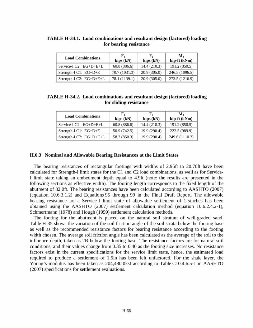
H-66
TABLE H-34.1. Load combinations and resultant design (factored) loading
for bearing resistance
Load Combinations F1 kips (kN)
F2 kips (kN)
M3 kip-ft (kNm)
Service-I C2: EG+D+E+L 60.8 (886.6) 14.4 (210.3) 191.2 (850.5) Strength-I C1: EG+D+E 70.7 (1031.3) 20.9 (305.0) 246.5 (1096.5) Strength-I C2: EG+D+E+L 78.1 (1139.1) 20.9 (305.0) 273.5 (1216.9)
TABLE H-34.2. Load combinations and resultant design (factored) loading for sliding resistance
Load Combinations F1
kips (kN) F2
kips (kN) M3
kip-ft (kNm) Service-I C2: EG+D+E+L 60.8 (886.6) 14.4 (210.3) 191.2 (850.5) Strength-I C1: EG+D+E 50.9 (742.5) 19.9 (290.4) 222.5 (989.9) Strength-I C2: EG+D+E+L 58.3 (850.3) 19.9 (290.4) 249.6 (1110.3)
H.6.3 Nominal and Allowable Bearing Resistances at the Limit States The bearing resistances of rectangular footings with widths of 2.95ft to 20.70ft have been
calculated for Strength-I limit states for the C1 and C2 load combinations, as well as for Service-I limit state taking an embedment depth equal to 4.9ft (note: the results are presented in the following sections as effective width). The footing length corresponds to the fixed length of the abutment of 82.0ft. The bearing resistances have been calculated according to AASHTO (2007) (equation 10.6.3.1.2) and Equations 95 through 99 in the Final Draft Report. The allowable bearing resistance for a Service-I limit state of allowable settlement of 1.5inches has been obtained using the AASHTO (2007) settlement calculation method (equation 10.6.2.4.2-1), Schmertmann (1978) and Hough (1959) settlement calculation methods.
The footing for the abutment is placed on the natural soil stratum of well-graded sand. Table H-35 shows the variation of the soil friction angle of the soil strata below the footing base as well as the recommended resistance factors for bearing resistance according to the footing width chosen. The average soil friction angle has been calculated as the average of the soil to the influence depth, taken as 2B below the footing base. The resistance factors are for natural soil conditions, and their values change from 0.35 to 0.40 as the footing size increases. No resistance factors exist in the current specifications for the service limit state, hence, the estimated load required to produce a settlement of 1.5in has been left unfactored. For the shale layer, the Young’s modulus has been taken as 204,480.0ksf according to Table C10.4.6.5-1 in AASHTO (2007) specifications for settlement evaluations.

H-67
Table H-35 Average soil friction angle and recommended resistance factor variation according to the footing size (thereby the influence depth) in natural soil condition
B (ft) Average φf (deg)
Recommended φ B (ft) Average
φf (deg) Recommended
φ 2.95 36.50 0.35 12.80 36.75 0.40 3.94 36.50 0.35 13.78 36.75 0.40 4.92 36.50 0.35 14.76 36.75 0.40 5.91 36.56 0.40 15.75 36.75 0.40 6.89 36.61 0.40 16.73 36.75 0.40 7.87 36.75 0.40 17.72 36.75 0.40 8.86 36.75 0.40 18.70 36.75 0.40 9.84 36.75 0.40 19.68 36.75 0.40
10.83 36.75 0.40 20.67 36.75 0.40 11.81 36.75 0.40
H.6.4 Design Footing Width
The largest load eccentricity caused by the load combinations related to Service-I and Strength-
I loads, according to the characteristic loadings listed in Table H-33, is 3.15ft from C2 combination. Hence, the minimum admissible footing due to limited eccentricity is of width Bmin = 18.9ft (=3.15ft×6) considering the limiting eccentricity as B/6. The maximum vertical loading in Strength-I C1 is 50.9kips/ft and Strength-I C2 is 58.3kips/ft while that in Service-I is 60.8kips/ft.
Figures H-16 and H-17 present the unfactored and factored bearing resistances for different effective footing widths. The bearing load intensities (stresses) are plotted in the upper figures, whereas the lower ones present the bearing loads per unit length of the foundation to be compatible with the load presentation. The footing width refers to the effective width for both bearing capacity and settlement analyses. While the settlement analyses were carried out for the geometrical (full) foundation width, in the presentation of Figures H-16 and H-17, the widths were transformed to be the effective widths.
Figure H-16 shows the variation of the unfactored bearing capacities with effective footing width for the two Strength limit states as well as for the Service limit state. The unfactored load combination C2 causes a larger load eccentricity but a smaller load inclination compared to the combination C1 (Table H-33). Because the effect of the load inclination on the bearing resistance is greater, the load combination C2 provides a higher unfactored resistance than the load combination C1. Figure H-17 shows the variation of factored bearing capacities with effective footing width for Strength-I C2 loading and unfactored bearing capacities for Service-I loading.
Applying the aforementioned vertical loads for the corresponding limit states in Figures H-17, the following results are obtained: (a) the minimum footing width (full size) required for the Strength-I limit state is B = 13.6ft, which is smaller than the minimum admissible footing of width Bmin = 18.9ft, and (b) the minimum effective footing widths required for Service-I loadings are B = 13.55ft (<Bmin) when AASHTO (2007) method of settlement estimation is used, while using Schmertmann (1978) and Hough (1959) methods result in a footing of minimum admissible width.

H-68
4 6 8 10 12 14 16 18 20Effective footing width, B′ (ft)
0
50
100
150
200
250
Unf
acto
red
resi
stan
ce (l
imit
stat
es) (
kip/
ft)
1.5 2.5 3.5 4.5 5.5Effective footing width, B′ (m)
0
1000
2000
3000
Unf
acto
red
resi
stan
ce (l
imit
stat
es) (
kN/m
)
4 6 8 10 12 14 16 18 20Effective footing width, B′ (ft)
-5
0
5
10
15
20
25
30
Unf
acto
red
resi
stan
ce (l
imit
stat
es) (
ksf)
1.5 2.5 3.5 4.5 5.5Effective footing width, B′ (m)
0
200
400
600
800
1000
1200
1400
Unf
acto
red
resi
stan
ce (l
imit
stat
es) (
kPa)
(1-way load inlination and 1-way eccentricity)Strength LS - Load combination C1Strength LS - Load combination C2Service LS − AASHTO (2007)Service LS − Schmertmann (1978)Service LS − Hough (1959)Service I loading
Figure H-16. Variation of unfactored bearing resistance for Strength-I and Service-I limit states with effective footing width for Example 6

H-69
4 6 8 10 12 14 16 18 20Effective footing width, B′ (ft)
0
5
10
15
20
25
Fact
ored
ulti
mat
e lim
it st
ate
and
unfa
ctor
ed se
rvic
e lim
it st
ate
(ksf
)
1.5 2.5 3.5 4.5 5.5Effective footing width, B′ (m)
0
200
400
600
800
1000
Fact
ored
ulti
mat
e lim
it st
ate
and
unfa
ctor
ed se
rvic
e lim
it st
ate
(kPa
)
Strength I LS − φ = 0.40 (Recom)Strength I LS − φ = 0.45 (AASHTO, 2007)Service LS − AASHTO (2007)Service LS − Schmertmann (1978)Service LS − Hough (1959)Strength I loadingService I loading
4 6 8 10 12 14 16 18 20Effective footing width, B′ (ft)
0
25
50
75
100
125
150
175
200
Fact
ored
ulti
mat
e lim
it sta
te a
ndun
fact
ored
serv
ice
limit
stat
e (k
ip/ft
)
1.5 2.5 3.5 4.5 5.5Effective footing width, B′ (m)
0
500
1000
1500
2000
2500
Fact
ored
ulti
mat
e lim
it sta
te a
ndun
fact
ored
serv
ice
limit
stat
e (k
N/m
)
Figure H-17. Variation of factored bearing resistance for Strength-I C2 and unfactored Service-I limit states with effective footing width for Example 6
H-70
The conclusions possible from Figures H-16 and H-17 are therefore:
1. Based on the strength limit state alone, the minimum admissible footing size (full geometry is required:
• Strength limit state φ = 0.35 to 0.40: 18.9 ft×82.0 ft • Strength limit state φ = 0.45 (current AASHTO): 18.9 ft×82.0 ft
2. Based on the unfactored serviceability limit state (current AASHTO), 18.9 ft×82.0 ft is required.
The footing dimensions obtained above for the factored service limit state provides a footing
larger than that obtained in GEC6 (of width 17.1 ft). In this example, it is seen that the minimum allowable footing size decided according to the limiting eccentricity governs the design when eB/B is taken as 1/6. In GEC6, the limiting eccentricity is taken as B/4, i.e. the minimum admissible width is 12.6ft. When the limiting eB/B is taken as ¼, the footing dimension obtained for factored strength limit state is 13.6ft and those obtained for unfactored serviceability limit state is 13.55ft when AASHTO (2007) method is used and 12.6ft when Schmertmann (1978) and Hough (1959) methods are used. Therefore, the Strength-I limit sate governs the design when limiting eccentricity of B/4 is used. Though in GEC6, Hough (1959) method of settlement estimation has been used with limiting eccentricity of B/4, the discrepancy in the widths can arise from the differences in the way different soil parameters are considered and the settlement calculation methods used. H.6.5 Sliding Resistance
The footing is cast in-place; the recommended resistance factor for cast in-place footings when
at-rest earth pressure is acting is φτ = 0.40 and that when active earth pressure is acting is φτ = 0.45, while the current AASHTO (2007) specification recommends φτ = 0.80.
Here, the lateral earth load considered during the design process is related to the active earth pressure. The back-fill is well-graded silty sand and gravel for which soil friction angle φf = 38°. The ratio of the lateral at-rest earth pressure coefficient to the lateral active earth pressure coefficient for the back-fill is K0 / Ka = (1 + sin φf ) = 1.616, assuming Rankine’s active earth pressure and at-rest earth pressure for normally consolidated cohessionless sand.
The abutment rests on well-graded sand with φf = 36.5°, therefore, the interfacial friction angle obtained from the recommended relation in this study is as follows:
tan(δs) = 0.91 tan(36.5) ⇒ δs = 33.95° For the designed footing, the minimum factored vertical load and the corresponding lateral
loads under Strength-I and Service-I loadings, thereby, the factored sliding resistance in each case are as follows. Service-I LS:
At-rest earth pressure: The minimum vertical load = 56.5kips/ft and the corresponding maximum total
lateral load = 14.4kips/ft (Table H-33, C1 combination) when active earth pressure is acting. Hence, the corresponding maximum total lateral load when at-rest earth pressure is acting is (refer to Tables H-32 and H-33):
( )2 0 14.4 11.5 1.616 11.5 21.48kips/ftEF = − + × = .
H-71
Factored sliding resistance φτF2E0 = 0.40 × 56.5×tan(33.95) = 15.2kips/ft < 21.5kips/ft Active earth pressure: Factored sliding resistance φτF2Ea = 0.45 × 56.5×tan(33.95) = 17.1kips/ft > 14.4kips/ft Current AASHTO: Factored sliding resistance φτF2τ = 0.80 × 56.5×tan(33.95)
= 30.4kips/ft > 21.5kips/ft > 14.4kips/ft Strength I LS:
At-rest earth pressure: The minimum vertical load = 50.9kips/ft, and the corresponding maximum lateral
load = 19.9kips/ft (Table H-34.2) when active earth pressure is acting. Hence, the corresponding maximum total lateral load when at-rest earth pressure is acting is (refer to Tables H-32 and H-34.2):
( )2 0 19.9 1.5 11.5 1.5 1.616 11.5 27.0kips/ftEF = − × + × × = Factored sliding resistance φτF2E0 = 0.40 × 56.5×tan(33.95) = 15.2kips/ft < 27.0kips/ft Active earth pressure: Factored sliding resistance φτF2Ea = 0.45 × 56.5×tan(33.95) = 17.1kips/ft < 19.9kips/ft Current AASHTO: Factored sliding resistance φτF2τ = 0.80 × 56.5×tan(33.95)
= 30.4kips/ft > 27.0kips/ft > 19.9kips/ft
This shows that the sliding resistance factors recommended in this study result in footings larger than the designed footing for design against sliding failure due to lateral loads involving at-rest as well as active earth pressures, except when unfactored lateral active earth pressure is considered. Since the design of abutment footings against sliding is critical, further study on the application of the resistance factors for sliding is necessary. H.6.6 Discussions and Conclusions
From Figures H-16 and H-17 it is seen that the limiting eccentricity governs the footing design
in this example when the limiting eccentricity is chosen as B/6. Further, within the range of the minimum admissible footing width, the recommended resistance factor is essentially φ = 0.40 (Table H-35). A footing of size 18.9ft×82.0ft fulfills the requirements for Strength-I and Service-I limit states. If, however, the limiting eccentricity is chosen as B/4, the minimum footing dimension required for Strength-I limit state is 13.6ft×82.0ft, whereas, that required for the Service-I limit state is equal to the minimum admissible footing size of 12.6ft×82.0ft except when AASHTO (2007) method is used for service limit state estimation. Hence Strength-I limit stated governs the design if limiting eccentricity of B/4 is considered. A footing of 18.9ft×82.0ft may be recommended for design.
H-72
H.7 EXAMPLE 7: NEW MARLBOROUGH BRIDGE, SOUTH ABUTMENT ON ROCK
H.7.1 General Information
The south abutment of the New Marlborough Bridge N-08-013 (2005) is analyzed in example 7. The New Marlborough bridge N-08-013 is a simple, single-span and short length span (SS-S). The constructed bridge dimensions and footing dimensions are: Bridge:
Span length 38.5ft (11.73m) Span width 32.2ft (9.81m)
Foundations: South Abutment Width = 10.5 ft (3.2m); length = 38.4ft (11.71m); average height of abutment from abutment footing base = 9.0ft
(2.75m); abutment wingwall –SE side = 20.5ft (6.25m), SW side = 17.2ft (5.25m)
North Abutment Width = 10.5 ft (3.8m); length = 38.4ft (11.71m); average height of abutment from abutment footing base = 9.0ft
(2.75m); abutment wingwall –NE side = 26.3ft (8.0m), NW side = 23.0ft (7.0m)
H.7.2 Subsurface Condition
The subsurface at the south abutment location based on boring B-1 consists of 6inch of asphalt
and 6inch of road base overlaying approximately 9.4ft of dry, loose to medium dense fine sand, with inorganic silt, and trace of gravel overlaying a quartzite rock layer. The geotechnical report (Mass Highway, 1999) called for placing the footing on a horizontal leveled rock ledge excavated at least 6inch deep. Based on boring B-1, the quartzite rock has an RQD of 59% up to a depth of 20.6ft (6.28m) to which drilled sample has been obtained. The point load strength has been reported to be 2,700psi.
The parameters provided in the geotechnical report for the gravel borrow used in the backfill are: bulk unit weight γ = 130.0pcf (20.4kN/m³) and internal friction angle φf = 35°. The groundwater table is located at elevation 851.7ft (259.6m) and the foundation base is at elevation of 856.3ft (261.0m), i.e. the GWT is 4.6ft (1.4m) below the footing base. Hence the backfill soil is assumed to be dry for the design purpose.
H.7.3 Loads, Load Combinations and Limit States
The provided load components are summarized in Table H-36. The loads are provided in units
of force per unit foundation length referring to the abutment length of 38.4ft (across the bridge). The dead (DL) load includes the weight of the superstructure and the abutment, whereas the vertical pressure from the dead load of earth fill is EV and earth surcharge load is ES. The investigated load combination and the resultant characteristic loading as well as the eccentricity e2 (refer to Figure 120 of Chapter 5 for load notations and directions) for the load combination considered is summarized in Table H-37. The loading produces one-way inclination and one-way eccentricity with a negative eccentricity (refer to Figure 69b in section 3.7). The design load

H-73
components required for the stability analysis, which are the factored characteristic loadings with load factors according to AASHTO Section 3 (2008) (presented in Tables H-4.1 and H-4.2), are summarized in Tables H-38.1 and H-38.2 for the bearing capacity and sliding strength limit states, respectively. Only Service-I and Strength-I limit states will be used here for the design of the footing width. Settlement evaluation is excluded but should be considered even if it is less likely to control the design of a footing on rock.
TABLE H-36. Loading at footing base for Example 7
Load at footing base F1
kip/ft (kN/m) F2
kip/ft (kN/m) M3
kip-ft/ft (kNm/m) dead load (DL) 15.2 (222.1) 0.0 -45.3 (-201.4) live load (LL) 1.9 (28.0) 0.0 -4.2 (-18.7) at-rest earth pressure (EH) 0.0 6.4 (93.6) 43.0 (191.1) Vertical load of earth fill (EV) 8.2 (119.7) 0.0 -63.0 (-280.3) earth surcharge (ES) 1.0 (14.1) 1.1 (16.0) 3.4 (15.0) live load surcharge (LS) 1.5 (22.3) 1.7 (25.3) -2.1 (-9.4)
TABLE H-37. Load combinations and resultant characteristic (unfactored) loading for Example 7
Load
combi-nations
Load components F1
kips/ft (kN/m)
F2 kips/ft (kN/m)
M3 kips-ft/ft (kNm/m)
F2/F1 e2 = M3/F1
ft (m)
C1 DL+LL+EH+EV+ES+LS 27.8 (406.2)
9.2 (134.9)
-68.3 (-303.6) 0.332 -7.383
(-2.250)
TABLE H-38.1. Load combinations and resultant design (factored) loading for bearing resistance
Limit state load combinations
F1 kip/ft (kN/m)
F2 kip/ft (kN/m)
M3 kip-ft/ft (kNm/m)
Service-I C1 27.8 (405.2) 9.2 (134.9) -68.3 (-303.6) Strength-I C1 37.6 (548.4) 13.3 (194.6) -89.6 (-398.8)
TABLE H-38.2. Load combinations and resultant design (factored) loading for sliding resistance
Limit state load
combinations F1
kip/ft (kN/m) F2
kip/ft (kN/m) M3
kip-ft/ft (kNm/m) Service-I C1 27.8 (405.2) 9.2 (134.9) -68.3 (-303.6) Strength-I C1 28.7 (418.2) 12.5 (182.6) -54.3 (-241.4)

H-74
H.7.4 Estimation of Rock Parameters Based on Table 11 (Deere, 1968) in section 1.8.2 of the report, the rockmass quality
corresponding to the given RQD of 59% is Fair. Using this information and Table 10.4.6.4-3 in AASHTO (2008) (Table 17 in section 1.8.3 of the report), the RMR ranges from 41 to 60. From Table 10.4.6.4-4 in AASHTO (2008) (Table 19 in section 1.8.3 of the report), for fair quality quartzite rock, the material constants are; m = 0.275 and s = 0.00009, and the joint spacing range from 1ft to 3ft. From Table 12 (Bieniawski, 1978) in section 1.8.2 of the report, for the Fair rockmass with 41≤ RMR ≤60, the internal friction angle of the rockmass lies between 25° and 35°. Hence a friction angle of 30° (hence Nφ = 0.30) and a joint spacing of 2ft (average of the ranges) have been adopted, similarly to the way the uncertainty of the methods have been established for calibration.
Based on the correlation between the point load strength and unconfined compressive strength proposed by Prakoso (2002), the unconfined compressive strength of the quartzite rockmass has been taken as
23.3 23.3 2700 62910psi 9059ksfu sq I= × = × = =
where Is is the point load strength. The rockmass Young’s modulus of elasticity, Em, for the quartzite rock of RQD = 59% has
been estimated based on the average Young’s modulus of elasticity of intact quartzite Ei and the ratio of Em to Ei given by O’Neill and Reese (1999) (Table 10.4.6.5-1 in AASTHO, 2008). The average Young’s modulus of elasticity for intact quartzite has been taken as Ei = 9.59×10⁻³ ksi (Table C10.4.6.5-1 in AASHTO, 2008) and the Em/Ei ratio for RQD = 59% is about 0.42. Hence, the rockmass modulus of elasticity, Em = 4.03×10⁻³ ksi. Average value of Poisson’s ratio for the rock has been taken as 0.14 (Table C10.4.6.5-2 in AASHTO, 2008).
H.7.5 Nominal and Allowable Bearing Resistances at the Limit States
The bearing resistances of rectangular footings with widths of 4.0ft to 14.0ft, with the footing
length kept fixed at 38.4ft according to the length of the abutment, have been calculated for Strength-I C1 limit state. Carter and Kulhawy (1988) method and Goodman (1989) method for non-fractured rockmass have been used to estimate the nominal bearing capacities. The recommended resistance factor in the present study as well as that recommended in AASHTO (2008) have been applied and the resulting footing widths compared. The recommended resistance factor to be used with Carter and Kulhawy (1988) method for the range of RMR established is φ = 1.00, and φ = 0.35 when the RMR range is not considered, while that to be used with Goodman (1989) method for both the joint spacing s′ and friction angle φf estimated from RQD is φ = 0.30. The resistance factor in the current AASHTO (2008) specifications is φ = 0.45, irrespective of the estimation method used.
For the footing on the quartzite rock with small Poisson’s ratio and large Em, the settlement can be expected to be very small, which is observed in the calculation of the allowable bearing resistance for the Service-I limit state using the AASHTO (2008) settlement calculation method (equation 10.6.2.4.4-3). No resistance factors had been yet established for the settlement evaluation.
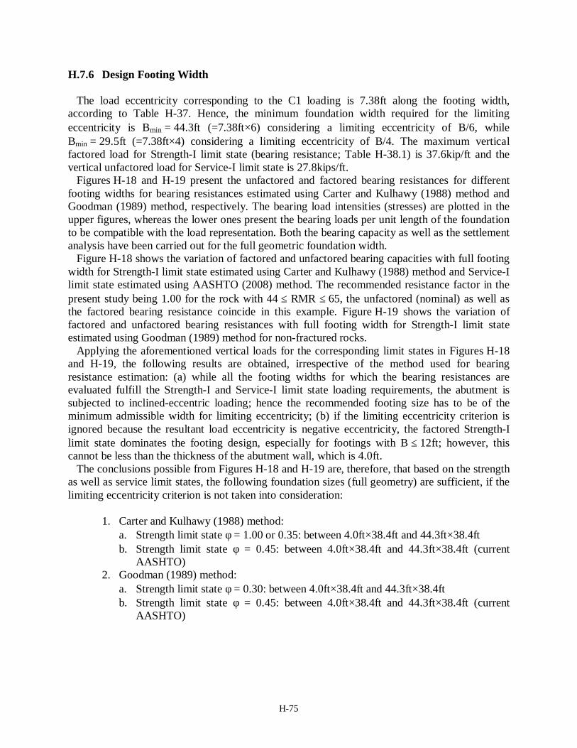
H-75
H.7.6 Design Footing Width The load eccentricity corresponding to the C1 loading is 7.38ft along the footing width,
according to Table H-37. Hence, the minimum foundation width required for the limiting eccentricity is Bmin = 44.3ft (=7.38ft×6) considering a limiting eccentricity of B/6, while Bmin = 29.5ft (=7.38ft×4) considering a limiting eccentricity of B/4. The maximum vertical factored load for Strength-I limit state (bearing resistance; Table H-38.1) is 37.6kip/ft and the vertical unfactored load for Service-I limit state is 27.8kips/ft.
Figures H-18 and H-19 present the unfactored and factored bearing resistances for different footing widths for bearing resistances estimated using Carter and Kulhawy (1988) method and Goodman (1989) method, respectively. The bearing load intensities (stresses) are plotted in the upper figures, whereas the lower ones present the bearing loads per unit length of the foundation to be compatible with the load representation. Both the bearing capacity as well as the settlement analysis have been carried out for the full geometric foundation width.
Figure H-18 shows the variation of factored and unfactored bearing capacities with full footing width for Strength-I limit state estimated using Carter and Kulhawy (1988) method and Service-I limit state estimated using AASHTO (2008) method. The recommended resistance factor in the present study being 1.00 for the rock with 44 ≤ RMR ≤ 65, the unfactored (nominal) as well as the factored bearing resistance coincide in this example. Figure H-19 shows the variation of factored and unfactored bearing resistances with full footing width for Strength-I limit state estimated using Goodman (1989) method for non-fractured rocks.
Applying the aforementioned vertical loads for the corresponding limit states in Figures H-18 and H-19, the following results are obtained, irrespective of the method used for bearing resistance estimation: (a) while all the footing widths for which the bearing resistances are evaluated fulfill the Strength-I and Service-I limit state loading requirements, the abutment is subjected to inclined-eccentric loading; hence the recommended footing size has to be of the minimum admissible width for limiting eccentricity; (b) if the limiting eccentricity criterion is ignored because the resultant load eccentricity is negative eccentricity, the factored Strength-I limit state dominates the footing design, especially for footings with B ≤ 12ft; however, this cannot be less than the thickness of the abutment wall, which is 4.0ft.
The conclusions possible from Figures H-18 and H-19 are, therefore, that based on the strength as well as service limit states, the following foundation sizes (full geometry) are sufficient, if the limiting eccentricity criterion is not taken into consideration:
1. Carter and Kulhawy (1988) method:
a. Strength limit state φ = 1.00 or 0.35: between 4.0ft×38.4ft and 44.3ft×38.4ft b. Strength limit state φ = 0.45: between 4.0ft×38.4ft and 44.3ft×38.4ft (current
AASHTO) 2. Goodman (1989) method:
a. Strength limit state φ = 0.30: between 4.0ft×38.4ft and 44.3ft×38.4ft b. Strength limit state φ = 0.45: between 4.0ft×38.4ft and 44.3ft×38.4ft (current
AASHTO)
H-76
4 6 8 10 12 14Footing width, B (ft)
0
1000
2000
3000
4000
5000
Lim
it st
ates
(ksf
)
1.5 2.5 3.5Footing width, B (m)
0
5000
10000
15000
20000
Lim
it sta
tes (
kPa)
4 6 8 10 12 14Footing width, B (ft)
10
100
1000
10000
100000
Lim
it st
ates
(kip
/ft)
1.5 2.5 3.5Footing width, B (m)
1000
10000
100000
1000000Li
mit
stat
es (k
N/m
)
Strength-I LS − nominalStrength-I LS − φ = 1.00 (Recommended)Strength-I LS − φ = 0.35 (Reco; RMR unknown)Strength-I LS − φ = 0.45 (AASHTO, 2008)Service-I LS − 1.00in settlementStrength-I C1 LoadService-I C1 Load
Figure H-18. Variation of factored bearing resistance for Strength-I C1 loading, estimated using Carter and Kulhawy (1988) method, with footing width for Example 7; loads are expressed
per unit length of the foundation (L = 38.4ft)

H-77
4 6 8 10 12 14Footing width, B (ft)
0
4000
8000
12000
16000
20000
Lim
it st
ates
(ksf
)
1.5 2.5 3.5Footing width, B (m)
0
200000
400000
600000
800000
Lim
it st
ates
(kPa
)
4 6 8 10 12 14Footing width, B (ft)
10
100
1000
10000
100000
1000000
Lim
it st
ates
(kip
/ft)
1.5 2.5 3.5Footing width, B (m)
1000
10000
100000
1000000
10000000Li
mit
stat
es (k
N/m
)
Strength-I LS − nominalStrength-I LS − φ = 0.30 (Recommended)Strength-I LS − φ = 0.45 (AASHTO, 2008)Service-I LS − 1.00in settlementStrength-I C1 LoadService-I C1 Load
Figure H-19 Variation of factored bearing resistance for Strength-I C1 loading, estimated using Goodman (1989) method for non-fractured rock, with footing width for Example 7; loads are
expressed per unit length of the foundation (L = 38.4ft)

H-78
For the constructed footing size of B = 10.5ft, the estimated factored bearing resistance using Carter and Kulhawy (1988) method is estimated to be 27.1×10³ kip/ft when RMR is considered for the selection of φ and 9.5×10³ kip/ft when RMR range is ignored; the factored bearing resistance is 28.4×10³ kip/ft using Goodman (1989) method, while the estimated load required for 1.0in settlement is 30.4×10³ kip/ft. All of these capacities fulfill the required Strength-I and Service-I LS loadings by very large margins. H.7.7 Sliding Resistance
The concrete/rock adhesion should result with an interface shear strength equal to the lower of
the two. Considering a reduction factor (beyond the scope of the presented research) should show sufficient width to resist all loads. For the purpose of demonstration only, the sliding resistance is evaluated assuming contact with granular material, serving also as the lowest possible resistance.
For φf = 30°, the interfacial friction angle between the footing base and the rock ledge obtained from the recommended relation in this study, though strictly valid from the interface of concrete and granular soils, is as follows:
tan(δs) = 0.91 tan(30.0) ⇒ δs = 27.7°
Note, in the actual design calculation, δs was taken as equal to 30°. The recommended resistance factor for cast in-situ footings when at-rest earth pressure is acting is φτ = 0.40 and that when active earth pressure is acting is φτ = 0.45. The current AASHTO (2007) specification recommends φτ = 0.80. Here, the lateral earth load considered during the design process is related to the at-rest earth pressure. For the back-fill with soil friction angle φf = 35°, the ratio of the lateral active earth pressure coefficient to the lateral at-rest earth pressure coefficient, Ka / K0 = 1 / (1 + sin φf ) = 1/1.574, assuming Rankine’s active earth pressure and at-rest earth pressure for normally consolidated cohessionless sand.
For the constructed footing of B = 10.5ft, the minimum factored vertical load and the corresponding lateral loads under Strength-I and Service-I loadings, thereby, the factored sliding resistance in each case are as follows. Service-I LS:
At-rest earth pressure: The minimum vertical load = 27.8kips/ft, and the corresponding lateral load =
6.4kips/ft from the earth pressure alone (Table H-38.2) δs = 27.7°: Sliding resistance φτF2τ = 0.40 × 27.8×tan(27.7) = 5.8kips/ft < 6.4kips/ft δs = 30.0°: Sliding resistance φτF2τ = 0.40 × 27.8×tan(30.0) = 6.4kips/ft = 6.4kips/ft Active earth pressure:
The corresponding lateral load involving active earth pressure is (Tables H-36 and H-38.2)
21 6.4 4.07kips/ft
1.574EaF = × = .
δs = 27.7°: Sliding resistance φτF2Ea = 0.45 × 27.8×tan(27.7) = 6.5kips/ft > 4.07kips/ft δs = 30.0°: Sliding resistance φτF2Ea = 0.45 × 27.8×tan(30.0) = 7.2kips/ft > 4.07kips/ft
H-79
Current AASHTO: δs = 27.7°: Sliding resistance φτF2τ = 0.80 × 27.8×tan(27.7) = 11.7kips/ft > 6.4kips/ft δs = 30.0°: Sliding resistance φτF2τ = 0.80 × 27.8×tan(30.0) = 12.8kips/ft > 6.4kips/ft
Strength I LS:
At-rest earth pressure: The minimum vertical load = 28.7kips/ft, and the corresponding lateral load =
9.6kips/ft (=1.50×6.4) from the earth pressure alone (Table H-38.2) δs = 27.7°: Sliding resistance φτF2τ = 0.40 ×28.7×tan(27.7) = 6.0kips/ft < 9.6kips/ft δs = 30.0°: Sliding resistance φτF2τ = 0.40 ×28.7×tan(30.0) = 6.6kips/ft < 9.6kips/ft Active earth pressure:
The corresponding lateral load involving factored active earth pressure is (load factors given in Table H-4.2)
211.50 6.4 6.10kips/ft
1.574i EaF γ = × × =
.
δs = 27.7°: Sliding resistance φτF2Ea = 0.45 × 28.7×tan(27.7) = 6.8kips/ft > 6.1kips/ft δs = 30.0°: Sliding resistance φτF2Ea = 0.45 × 28.7×tan(30.0) = 7.4kips/ft > 6.1kips/ft Current AASHTO: δs = 27.7°: Sliding resistance φτF2τ = 0.80 × 28.7×tan(27.7) = 12.0kips/ft > 9.6kips/ft δs = 30.0°: Sliding resistance φτF2τ = 0.80 × 28.7×tan(30.0) = 13.2kips/ft > 9.6kips/ft
This shows that the footing of width B = 10.5ft is safe in sliding except when the at-rest earth
pressure for Service-I LS vertical load is acting and φτ recommended in the present study is applied to the sliding resistance. The interfacial friction angle δs either can be assumed to be equal to 30.0° or can be obtained from the correlation presented.
H.7.8 Discussions and Conclusions
The design footing width required for limiting the eccentricity is found to be very large; 44.3ft
if limiting eccentricity of B/6 is considered or 29.5ft if B/4 is considered. The load eccentricity in this example creates negative eccentricity, which acts “in favor” in terms of bearing capacity as has been discussed in section 3.7 (Loading direction effect for inclined eccentric loading) and shown in Figure 69 in section 3.7 of the report. Without considering the limiting eccentricity, a small footing of size B = 4.0ft is found to be sufficient for bearing resistances in Strength as well as Service limit states. Strength-I limit state governs the design for B ≤ 12.0ft. The recommended footing is between 4.0ft×38.4ft and 12.0ft×38.4ft, at the discretion of the geotechnical and structural engineer, depending on the local practice.
H-80
REFERENCES
AASHTO (2007). LRFD Bridge Design Specifications Section 10: Foundations, American Association of State Highway & Transportation Officials, Washington, DC.
AASHTO (2008). LRFD Bridge Design Specifications Section 10: Foundations, American Association of State Highway & Transportation Officials, Washington, DC.
Bieniawski, Z.T. (1978). “Determining Rock Mass Deformability: Experience from Case Histories”, Int. Journal Rock Mechanics Min. Sci. and Geomech., Abstract, 15:237-248.
Carter, J.P., and F.H. Kulhawy (1988). Analysis and Design of Foundations Socketed into Rock. Report No. EL-5918, Empire State Electric Engineering Research Corporation and Electric Power Research Institute, New York, NY, p. 158.
Cheney, R.S., and Chassie, R.G. (1982). Soils and Foundations Workshop Manual, FHWA Report no. FHWA-NHI-88-009, NHI Course No. 13212, Washington, DC, 338pp.
Goodman, R.E. (1989) Introduction to Rock Mechanics. Second Edition, John Wiley & Sons. Hough, B.K. (1959). “Compressibility as the Basis for Soil Bearing Value,” Journal of the Soil
Mechanics and Foundations Division, ASCE, Vol. 85, No. SM4, August, pp.11-40. Kimmerling, R. E. (2002). Geotechnical Engineering Circular No. 6 Shallow Foundations,
FHWA Report no. FHWA-IF-02-054, Washington, D.C., 310pp Kulhawy, F. and Mayne, P. (1990). Manual on Estimation of Soil Properties for Foundation
Design, Report EPRI-EL-6800, Electric Power Research Institute, Palo Alto, California Liao, S.S.C., and Whitman, R.V. (1986). “Overburden Correction Factors for SPT in Sand”,
Journal of Geotechnical Engineering, ASCE, Vol.112, No.3, pp.373-377. Mass Highway (1999). “Geotechnical Report Bridge N-8-13 Mill River Road Over Konkapot River New Marlborough”, internal geotechnical report submitted by Haig Merguerian to the Massachusetts Highway Department, May 1999. O’Neill, M.W. and Reese, L.C. (1999). Drilled Shafts: Construction, Procedures and Design
Methods, ADSC-TL-4, FHWA-IF-99-025. Peck, R. B., Hanson, W. E. and Thornburn, T. H. (1974). Foundation Engineering, John Wiley
and Sons, New York Prakoso, W. A. (2002). Reliability-Based Design of foundations on rock masses for transmission
line and similar structures, PhD dissertation, Cornell University. Schmertmann, J.H., and Hartman, J.P. and Brown, P.R. (1978). “Improved Strain Influence
Factor Diagrams,” Journal of the Geotechnical Engineering Division, ASCE, Vol.104, No. GT8, pp113-1135.
URS. (2001). Geotechnical Design Report for Bridge No. B-12-025: Rangeway Road over Route 3, Route 3 North Transportation Improvements Project, Final Report, URS, Wayne, New Jersey