Embed Size (px)
Citation preview
Page 1
www.sensata.comCopyright © 2017 Sensata Technologies Inc.
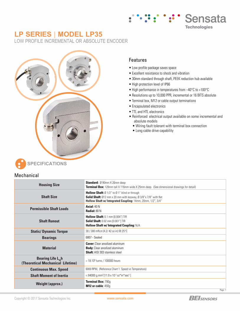
LP SERIES | MODEL LP35LOW PROFILE INCREMENTAL OR ABSOLUTE ENCODER
SPECIFICATIONS
Features
Mechanical
• Low profile package saves space• Excellent resistance to shock and vibration• 30mm standard through shaft, PEEK reduction hub available• High protection level of IP66• High performance in temperatures from –40°C to +100°C• Resolutions up to 10,000 PPR, incremental or 16 BITS absolute• Terminal box, M12 or cable output terminations• Encapsulated electronics• TTL and HTL electronics• Reinforced electrical output available on some incremental and
absolute models• Wiring fault tolerant with terminal box connection• Long cable drive capability
Housing SizeStandard: Ø 90mm X 26mm deepTerminal Box: 128mm tall X 116mm wide X 25mm deep. (See dimensional drawings for detail)
Shaft SizeHollow Shaft: Ø 1/2” to Ø 1” blind or throughSolid Shaft: Ø12 mm x 20 mm with keyway, Ø 3/8“x 7/8“ with flatHollow Shaft w/ Integrated Coupling: 14mm, 20mm, 1/2”, 3/4”
Permissible Shaft LoadsAxial: 40 NRadial: 80 N
Shaft RunoutHollow Shaft: 0.1 mm [0.004”] TIRSolid Shaft: 0.02 mm [0.001”] TIRHollow Shaft w/ Integrated Coupling: N/A
Static/ Dynamic Torque 30 / 300 mN.m [4.2/ 42 oz-in] @ 25°C
Bearings 6807 - Sealed
MaterialCover: Clear anodized aluminumBody: Clear anodized aluminumShaft: AISI 303 stainless steel
Bearing Life L10h(Theoretical Mechanical Lifetime)
> 18.109 turns / 100000 hours
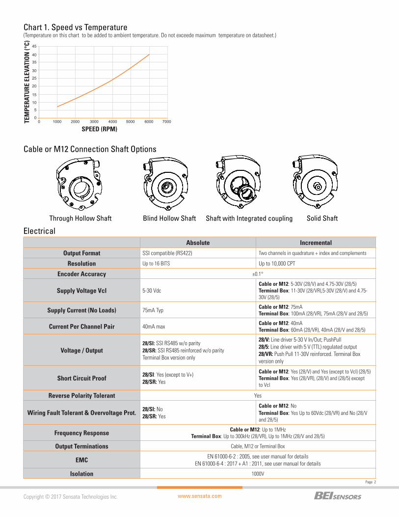
Continuous Max. Speed 6000 RPM, (Reference Chart 1. Speed vs Temperature)
Shaft Moment of Inertia < 84000 g.mm2 [11.9 x 10⁻³ oz*in*sec2 ]
Weight (approx.)Terminal Box: 790gM12 or cable: 450g
www.sensata.com
Page 2
Copyright © 2017 Sensata Technologies Inc.
Electrical
Cable or M12 Connection Shaft Options
Through Hollow Shaft Blind Hollow Shaft Shaft with Integrated coupling Solid Shaft
TEM
PERA
TURE
ELE
VATI
ON
(°C)
SPEED (RPM)
0
5
10
15
20
25
30
35
40
45
0 1000 2000 3000 4000 5000 6000 7000
Chart 1. Speed vs Temperature(Temperature on this chart to be added to ambient temperature. Do not exceede maximum temperature on datasheet.)
Absolute Incremental
Output Format SSI compatible (RS422) Two channels in quadrature + index and complements
Resolution Up to 16 BITS Up to 10,000 CPT
Encoder Accuracy ±0.1°
Supply Voltage Vcl 5-30 VdcCable or M12: 5-30V (28/V) and 4.75-30V (28/5)Terminal Box: 11-30V (28/VR),5-30V (28/V) and 4.75-30V (28/5)
Supply Current (No Loads) 75mA Typ Cable or M12: 75mATerminal Box: 100mA (28/VR), 75mA (28/V and 28/5)
Current Per Channel Pair 40mA max Cable or M12: 40mATerminal Box: 60mA (28/VR), 40mA (28/V and 28/5)
Voltage / Output28/SI: SSI RS485 w/o parity 28/SR: SSI RS485 reinforced w/o parityTerminal Box version only
28/V: Line driver 5-30 V In/Out; PushPull 28/5: Line driver with 5 V (TTL) regulated output 28/VR: Push Pull 11-30V reinforced. Terminal Box version only
Short Circuit Proof 28/SI: Yes (except to V+) 28/SR: Yes
Cable or M12: Yes (28/V) and Yes (except to Vcl) (28/5)Terminal Box: Yes (28/VR), (28/V) and (28/5) except to Vcl
Reverse Polarity Tolerant Yes
Wiring Fault Tolerant & Overvoltage Prot. 28/SI: No 28/SR: Yes
Cable or M12: NoTerminal Box: Yes Up to 60Vdc (28/VR) and No (28/V and 28/5)
Frequency Response Cable or M12: Up to 1MHzTerminal Box: Up to 300kHz (28/VR), Up to 1MHz (28/V and 28/5)
Output Terminations Cable, M12 or Terminal Box
EMC EN 61000-6-2 : 2005, see user manual for details EN 61000-6-4 : 2017 + A1 : 2011, see user manual for details
Isolation 1000V
www.sensata.comCopyright © 2017 Sensata Technologies Inc.
Page 3
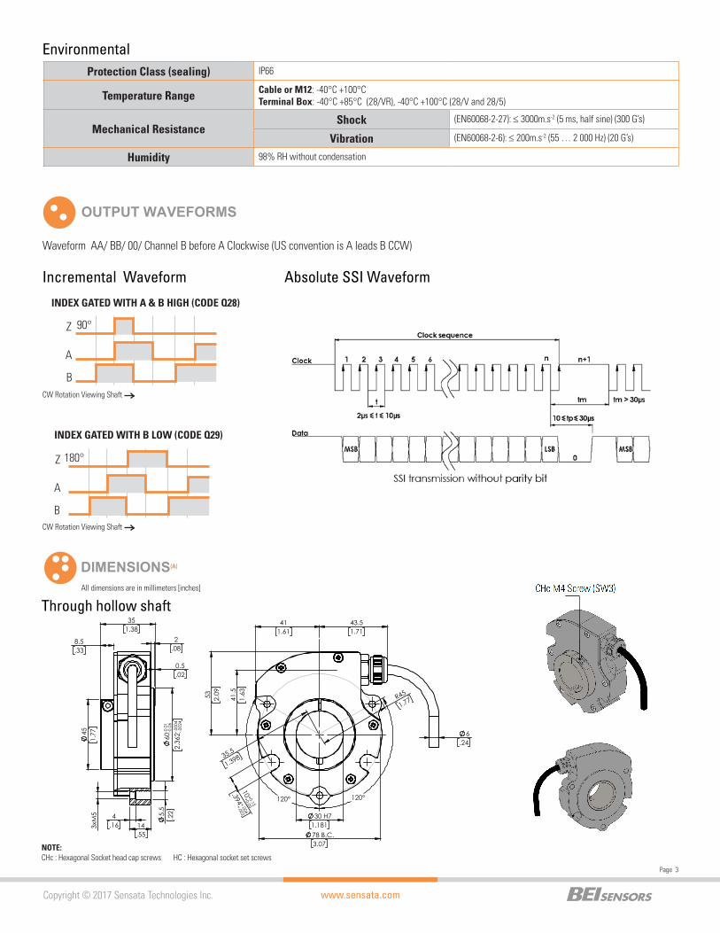
INDEX GATED WITH A & B HIGH (CODE Q28)
90°
A
Z
B
INDEX GATED WITH B LOW (CODE Q29)
180°
A
Z
B
OUTPUT WAVEFORMS
Waveform AA/ BB/ 00/ Channel B before A Clockwise (US convention is A leads B CCW)
Absolute SSI WaveformIncremental Waveform
Environmental
CW Rotation Viewing Shaft
CW Rotation Viewing Shaft
Protection Class (sealing) IP66
Temperature Range Cable or M12: -40°C +100°C Terminal Box: -40°C +85°C (28/VR), -40°C +100°C (28/V and 28/5)
Mechanical ResistanceShock (EN60068-2-27): ≤ 3000m.s-2 (5 ms, half sine) (300 G’s)
Vibration (EN60068-2-6): ≤ 200m.s-2 (55 … 2 000 Hz) (20 G’s)
Humidity 98% RH without condensation
DIMENSIONS(A)
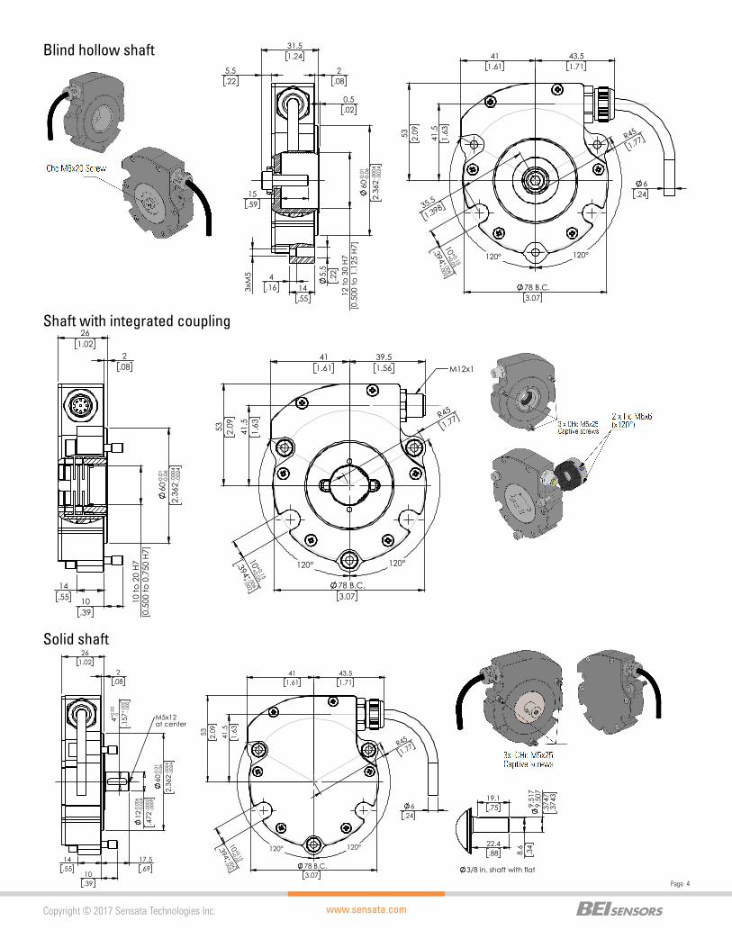
NOTE: CHc : Hexagonal Socket head cap screws HC : Hexagonal socket set screws
Through hollow shaft All dimensions are in millimeters [inches]
53 2.09
41.5
1.63 R45
1.77
43.51.71
35.5
1.398
411.61
10 ++ 0.150.05
.394 ++ .006.002
6.24
120° 120°
78 B.C.3.07
30 H71.181
351.38
60- -0.
010.
06
2.36
2- -.000
4.0
024
5.5
.22
14.55
4.16 3xM
5
0.5.02
2.08
8.5.33
451.
77
www.sensata.com
Page 4
Copyright © 2017 Sensata Technologies Inc.
Shaft with integrated coupling
Solid shaft
Blind hollow shaft
53 2.09
41.5
1.63 R45
1.77
35.5
1.398
411.61
10 ++ 0.150.05
.394 ++ .006.002
6.24
43.51.71
120° 120°
78 B.C.3.07
60- -0.
010.
06
2.36
2- -.000
4.0
024
5.5
.22
14.55
4.16 3
xM5
0.5.02
2.08
5.5.22
31.51.24
12 to
30
H7
[0.5
00 to
1.1
25 H
7]
15.59
53 2.09
411.61
39.51.56
R45
1.77
10 ++ 0.150.05
.394 ++ .006.002
120° 120° 78 B.C.3.07
41.5
1.63
M12x1
261.02
2.08
10
to 2
0 H7
[0
.500
to 0
.750
H7]
60- -0.
010.
06
2.36
2- -.000
4.0
024
14.55 10
.39
53 2.09
411.61
R45
1.77
10 ++ 0.150.05
.394 ++ .006.002
6.24
43.51.71
120° 120° 78 B.C.3.07
41.5
1.63
261.02
2.08
60- -0.
010.
06
2.36
2- -.000
4.0
024
14.55
10.39
12- -0.
006
0.02
4
.472
- -.000
2.0
009
4+
0.05
0
.157
+ -.002
.000
17.5.69
M5x12at center
9.51
79.
507
.374
7.3
74319.1
.75
22.4.88 8.
6.3
4
3/8 in. shaft with flat
www.sensata.comCopyright © 2017 Sensata Technologies Inc.
Page 5
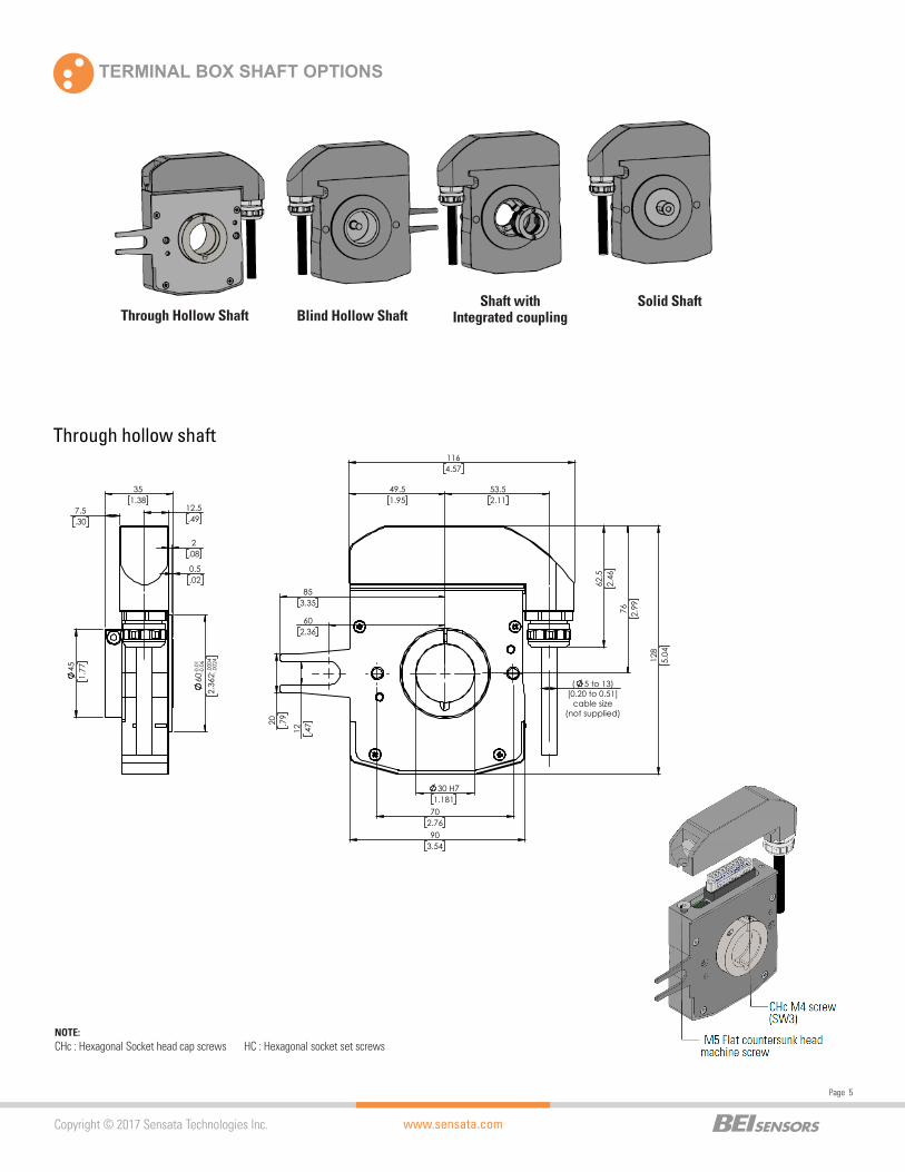
TERMINAL BOX SHAFT OPTIONS
Through hollow shaft
NOTE: CHc : Hexagonal Socket head cap screws HC : Hexagonal socket set screws
Through Hollow Shaft Blind Hollow ShaftShaft with
Integrated couplingSolid Shaft
12 .4720 .7
9
903.54
602.36
853.35
702.76
53.52.11
49.51.95
1164.57
128
5.04
76 2.99
62.5
2.46
( 5 to 13) [0.20 to 0.51]
cable size(not supplied)
30 H71.181
351.38
7.5.30
451.
77
12.5.49
60- -0.
010.
06
2.36
2- -.000
4.0
024
2.08
0.5.02
www.sensata.com
Page 6
Copyright © 2017 Sensata Technologies Inc.
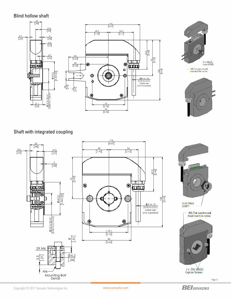
Blind hollow shaft
Shaft with integrated coupling
12 .4720 .7
9
903.54
602.36
853.35
702.76
53.52.11
49.51.95
1164.57
128
5.04
76 2.99
62.5
2.46
( 5 to 13) [0.20 to 0.51]
cable size(not included)
5.7.22
60- -0.
010.
06
2.36
2- -.000
4.0
024
25.98
2.08
0.5.02
12.5.49
12 to
30
H7
0.50
0 to
1.1
25 H
7
21.1.83
6.7.26
1164.57
62.5
2.46
= 70 =2.76
491.93
542.13
128
5.04
76 2.99
5 to 13 [0.20 to 0.51]
cable size(not supplied)
903.54
25.98
2.08
5.6.22
14.5.57
60- -0.
010.
06
2.36
2- -.000
4.0
024
10 to
20
H7
[0.5
0 to
0.7
5 H7
)
6.2.24
2X M6
8 .31
5.5
.21
Mounting BoltDetail
M6

www.sensata.comCopyright © 2017 Sensata Technologies Inc.
Page 7
TETHER OPTIONS FOR STANDARD CABLE OR M12 CONNECTOR
Other options available, consult factory. Tethers come with all the hardware shown.
T2- Long tether arm with ¼”-20 adj. hardware – M9445/053-02 T3-Short tether arm with ¼”-20 adj, hardware (fits 56C) – M9445/058-02
552,17
25 0,98
44,5
1,75
12 0,47
18.3
/ 28
.30,
72 /
1.11
1/4"-20 with hex nuts
762,99
1024,02
1556,10
1184,65
1445,67
26 1,02
12 0,47
30° Typ
72,42,85
77,43,05
12 0,47
26 1,02
90,23,55
30° Typ
25 0,98
44,5
1,75
18.3
/ 28
.30,
72 /
1.11
12 0,47
501,97
1/4"-20 x 2" with hex nuts
Solid shaft 1164.57
62.5
2.46
= 70 =2.756
76 2.99
5 to 13 [0.20 to 0.51]
cable size(not supplied)
903.543
542.13
491.93
128
5.04
25.98
14.5.57
2.08
17.5.69
4+0.1 0
.157
+ -.002
.000
12- -0.
006
0.02
4
.472
- -.000
2.0
009
60- -0.
010.
06
2.36
2- -.000
4.0
024
5.6.22
9.51
79.
507
.374
7.3
743
22.4.88
19.1.75
8.6
.34
3/8 in. Shaft with Flat
www.sensata.com
Page 8
Copyright © 2017 Sensata Technologies Inc.
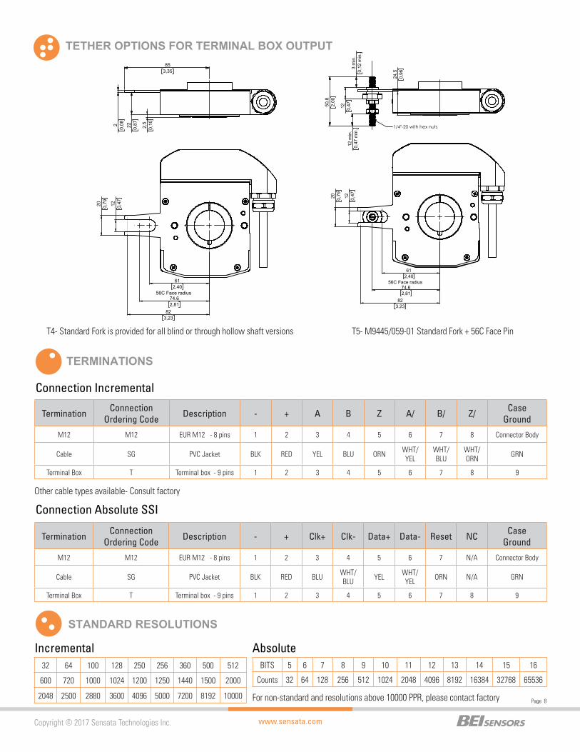
Connection Incremental
Connection Absolute SSI
Incremental Absolute
Termination Connection Ordering Code Description - + A B Z A/ B/ Z/ Case
Ground
M12 M12 EUR M12 - 8 pins 1 2 3 4 5 6 7 8 Connector Body
Cable SG PVC Jacket BLK RED YEL BLU ORN WHT/YEL
WHT/ BLU
WHT/ ORN GRN
Terminal Box T Terminal box - 9 pins 1 2 3 4 5 6 7 8 9
TERMINATIONS
Other cable types available- Consult factory
TETHER OPTIONS FOR TERMINAL BOX OUTPUT
T4- Standard Fork is provided for all blind or through hollow shaft versions T5- M9445/059-01 Standard Fork + 56C Face Pin20 0,79 12 0,47
56C Face radius 74.62,81
612,40
823,23
50,8
2,00
24,5
0,96
12 m
in.
0,47
min
.
12 0,47
3 m
in.
0,12
min
.
1/4"-20 with hex nuts
20 0,79 12 0,47
56C Face radius 74.62,81
612,40
823,23
22 0,872
0,08
853,35
2,5
0,10
Termination Connection Ordering Code Description - + Clk+ Clk- Data+ Data- Reset NC Case
Ground
M12 M12 EUR M12 - 8 pins 1 2 3 4 5 6 7 N/A Connector Body
Cable SG PVC Jacket BLK RED BLU WHT/BLU YEL WHT/
YEL ORN N/A GRN
Terminal Box T Terminal box - 9 pins 1 2 3 4 5 6 7 8 9
STANDARD RESOLUTIONS
For non-standard and resolutions above 10000 PPR, please contact factory
32 64 100 128 250 256 360 500 512
600 720 1000 1024 1200 1250 1440 1500 2000
2048 2500 2880 3600 4096 5000 7200 8192 10000
BITS 5 6 7 8 9 10 11 12 13 14 15 16
Counts 32 64 128 256 512 1024 2048 4096 8192 16384 32768 65536
www.sensata.comCopyright © 2017 Sensata Technologies Inc.
Page 9
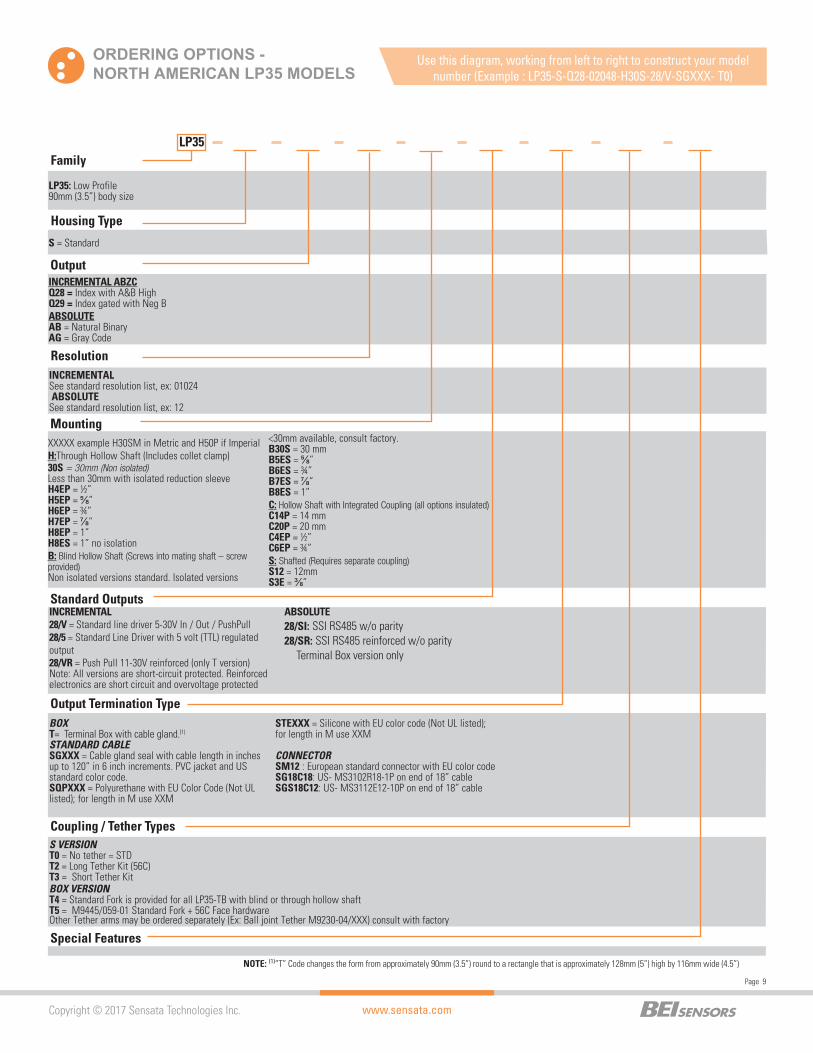
ORDERING OPTIONS -NORTH AMERICAN LP35 MODELS
INCREMENTAL See standard resolution list, ex: 01024 ABSOLUTE See standard resolution list, ex: 12
Mounting
Standard Outputs
Output Termination Type
Coupling / Tether Types
Special Features
XXXXX example H30SM in Metric and H50P if ImperialH:Through Hollow Shaft (Includes collet clamp)30S = 30mm (Non isolated)Less than 30mm with isolated reduction sleeveH4EP = ½”H5EP = ” H6EP = ¾”H7EP = ”H8EP = 1”H8ES = 1” no isolationB: Blind Hollow Shaft (Screws into mating shaft – screw provided)Non isolated versions standard. Isolated versions
<30mm available, consult factory.B30S = 30 mmB5ES = ”B6ES = ¾”B7ES = ”B8ES = 1”C: Hollow Shaft with Integrated Coupling (all options insulated)C14P = 14 mmC20P = 20 mmC4EP = ½”C6EP = ¾”S: Shafted (Requires separate coupling)S12 = 12mmS3E = ”
INCREMENTAL28/V = Standard line driver 5-30V In / Out / PushPull28/5 = Standard Line Driver with 5 volt (TTL) regulated output28/VR = Push Pull 11-30V reinforced (only T version)Note: All versions are short-circuit protected. Reinforced electronics are short circuit and overvoltage protected
ABSOLUTE28/SI: SSI RS485 w/o parity 28/SR: SSI RS485 reinforced w/o parity
Terminal Box version only
BOXT= Terminal Box with cable gland.(1) STANDARD CABLESGXXX = Cable gland seal with cable length in inches up to 120” in 6 inch increments. PVC jacket and US standard color code.SQPXXX = Polyurethane with EU Color Code (Not UL listed); for length in M use XXM
STEXXX = Silicone with EU color code (Not UL listed); for length in M use XXM
CONNECTORSM12 : European standard connector with EU color code SG18C18: US- MS3102R18-1P on end of 18” cableSGS18C12: US- MS3112E12-10P on end of 18” cable
S VERSIONT0 = No tether = STDT2 = Long Tether Kit (56C)T3 = Short Tether KitBOX VERSIONT4 = Standard Fork is provided for all LP35-TB with blind or through hollow shaftT5 = M9445/059-01 Standard Fork + 56C Face hardwareOther Tether arms may be ordered separately (Ex: Ball joint Tether M9230-04/XXX) consult with factory
FamilyLP35
Housing Type
Output
Resolution
LP35: Low Profile90mm (3.5”) body size
S = Standard
INCREMENTAL ABZCQ28 = Index with A&B HighQ29 = Index gated with Neg BABSOLUTEAB = Natural BinaryAG = Gray Code
Use this diagram, working from left to right to construct your model number (Example : LP35-S-Q28-02048-H30S-28/V-SGXXX- T0)
NOTE: (1)“T” Code changes the form from approximately 90mm (3.5”) round to a rectangle that is approximately 128mm (5”) high by 116mm wide (4.5”)
www.sensata.comSpecification No. 02160-00_Rev.01/05/18
Page 10
CONTACT US
Americas+1 (800) 350 2727 – Option 1 [email protected], Middle East & Africa+33 (3) 88 20 [email protected] [email protected] +86 (21) 2306 1500Japan +81 (45) 277 7117Korea +82 (31) 601 2004India +91 (80) 67920890Rest of Asia +886 (2) 27602006 ext 2808
Copyright © 2017 Sensata Technologies, Inc.
Sensata Technologies, Inc. (“Sensata”) data sheets are solely intended to assist designers (“Buyers”) who are developing systems that incorporate Sensata products (also referred to herein as “components”). Buyer understands and agrees that Buyer remains responsible for using its independent analysis, evaluation and judgment in designing Buyer’s systems and products. Sensata data sheets have been created using standard laboratory conditions and engineering practices. Sensata has not conducted any testing other than that specifically described in the published documentation for a particular data sheet. Sensata may make corrections, enhancements, improvements and other changes to its data sheets or components without notice.Buyers are authorized to use Sensata data sheets with the Sensata component(s) identified in each particular data sheet. HOWEVER, NO OTHER LICENSE, EXPRESS OR IMPLIED, BY ESTOPPEL OR OTHERWISE TO ANY OTHER SENSATA INTELLECTUAL PROPERTY RIGHT, ANDNO LICENSE TO ANY THIRD PARTY TECHNOLOGY OR INTELLECTUAL PROPERTY RIGHT, IS GRANTED HEREIN. SENSATA DATA SHEETS ARE PROVIDED “AS IS”. SENSATA MAKES NO WARRANTIES OR REPRESENTATIONS WITH REGARD TO THE DATA SHEETS OR USE OF THE DATA SHEETS, EXPRESS, IMPLIED OR STATUTORY, INCLUDING ACCURACY OR COMPLETENESS. SENSATA DISCLAIMS ANY WARRANTY OF TITLE AND ANY IMPLIED WARRANTIES OF MERCHANTABILITY, FITNESS FOR A PARTICULAR PURPOSE, QUIET ENJOYMENT, QUIET POSSESSION, AND NON-INFRINGEMENT OF ANY THIRD PARTY INTELLECTUAL PROPERTY RIGHTS WITH REGARD TO SENSATA DATA SHEETS OR USE THEREOF.All products are sold subject to Sensata’s terms and conditions of sale supplied at www.sensata.com SENSATA ASSUMES NO LIABILITY FOR APPLICATIONS ASSISTANCE OR THE DESIGN OF BUYERS’ PRODUCTS. BUYER ACKNOWLEDGES AND AGREES THAT IT IS SOLELY RESPONSIBLE FOR COMPLIANCE WITH ALL LEGAL, REGULATORY AND SAFETY-RELATED REQUIREMENTS CONCERNING ITS PRODUCTS, AND ANY USE OF SENSATA COMPONENTS IN ITS APPLICATIONS, NOTWITHSTANDING ANY APPLICATIONS-RELATED INFORMATION OR SUPPORT THAT MAY BE PROVIDED BY SENSATA.Mailing Address: Sensata Technologies, Inc., 529 Pleasant Street, Attleboro, MA 02703, USA.
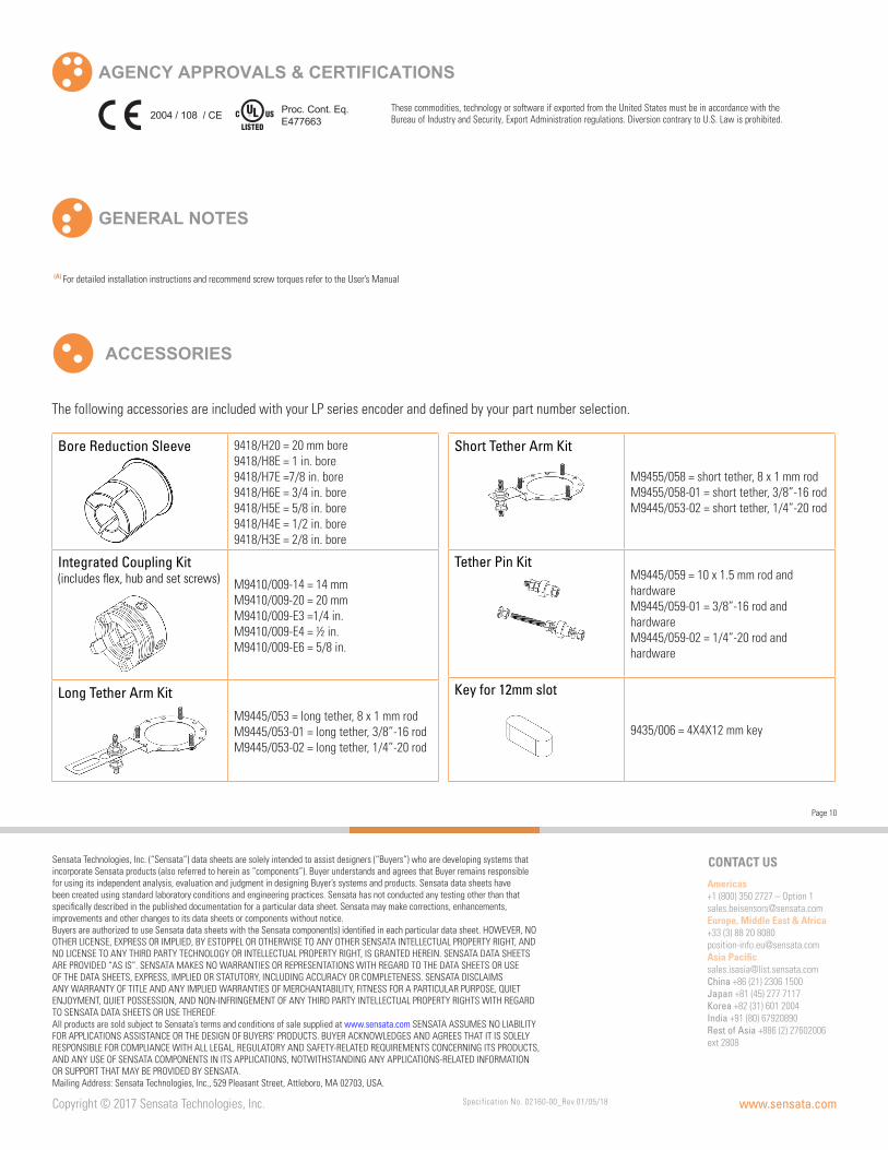
AGENCY APPROVALS & CERTIFICATIONS
GENERAL NOTES
These commodities, technology or software if exported from the United States must be in accordance with the Bureau of Industry and Security, Export Administration regulations. Diversion contrary to U.S. Law is prohibited.2004 / 108 / CE Proc. Cont. Eq.
E477663
(A) For detailed installation instructions and recommend screw torques refer to the User’s Manual
ACCESSORIES
The following accessories are included with your LP series encoder and defined by your part number selection.
Bore Reduction Sleeve 9418/H20 = 20 mm bore9418/H8E = 1 in. bore9418/H7E =7/8 in. bore9418/H6E = 3/4 in. bore9418/H5E = 5/8 in. bore9418/H4E = 1/2 in. bore9418/H3E = 2/8 in. bore
Integrated Coupling Kit (includes flex, hub and set screws) M9410/009-14 = 14 mm
M9410/009-20 = 20 mmM9410/009-E3 =1/4 in.M9410/009-E4 = ½ in.M9410/009-E6 = 5/8 in.
Long Tether Arm Kit
M9445/053 = long tether, 8 x 1 mm rodM9445/053-01 = long tether, 3/8”-16 rodM9445/053-02 = long tether, 1/4”-20 rod
Short Tether Arm Kit
M9455/058 = short tether, 8 x 1 mm rodM9455/058-01 = short tether, 3/8”-16 rodM9445/053-02 = short tether, 1/4”-20 rod
Tether Pin KitM9445/059 = 10 x 1.5 mm rod and hardwareM9445/059-01 = 3/8”-16 rod and hardwareM9445/059-02 = 1/4”-20 rod and hardware
Key for 12mm slot
9435/006 = 4X4X12 mm key


![Supplier Quality Manual - Sensata Technologies 1004255 SENSATA GSQM_rev R.pdfAdvanced Product Quality Planning [APQP] 23 9.5 . Special Characteristics SC [Key Product Characteristics](https://img.dokumen.tips/doc/110x75/5e24d9355e98e958745d5a8e/supplier-quality-manual-sensata-technologies-1004255-sensata-gsqmrev-rpdf-advanced.jpg)