Embed Size (px)
Citation preview

Lower Fox River Site Operation & Maintenance Plan
for the Water Treatment Plant
VOLUME I
Prepared for Appleton Papers Inc.
Georgia-Pacific Consumer Products LP NCR Corporation
For Submittal to Wisconsin Department of Natural Resources
U.S. Environmental Protection Agency
Prepared by Tetra Tech EC, Inc.
June 2009 EPA Region 5 Records Ctr.
376921
Document Control Number: LFRR-09-0219
Package Status Date Prepared Bv Approved Bv Pages Affected RevO 6/30/09 M.R.Bilimoria R.J. Feeney All
J. Francis
9/18/09

"It TETRATECHEC.INC.
Lower Fox River Remedial Action OUs 2-5
CONTROLLED DOCUMENT FORM
CONTRACTOR:
PROJECT NO.:
PROJECT NAME:
DOCUMENT CONTROL NO.
WORK PHASE:
DATE OF DOCUMENT:
DOCUMENT TITLE:
RECIPIENT GROUP:
SPECIFICATION SECTION AND PARAGRAPH NO. OF REQUIREMENT:
RECIPIENT:
METHOD OF DELIVERY:
SUBMITTED MATERIALS:
FILE NO.:
Tetra Tech EC Inc.
106-3876
Lower Fox River Remediation of OUs 2-5
LFRR-09-0219
2B
June 2009 Operation & Maintenance Plan for the Water Treatment Plant
Volume I
US Environmental Protection Agency
Name Jim Hahnenberg - USEPA
Address Chicago, IL 60604
Phone (312)353-42134
Paper Copy
Volume I & Volume II (Appendices A through E)
10.1.4 WTP O&M Plan
CONTROLLED DOCUMENT NO.: LFRR-09-0219-006
THIS FORM MUST REMAIN WITH THE ASSOCIATED DOCUMENT
September 2009 Rev. 0

Lower Fox River Site Operation & Maintenance Plan
for the Water Treatment Plant
VOLUME I
Prepared for Appleton Papers Inc.
Georgia-Pacific Consumer Products LP NCR Corporation
For Submittal to Wisconsin Department of Natural Resources
U.S. Environmental Protection Agency
Prepared by Tetra Tech EC, Inc.
August 2009
Document Control Number: LFRR-09-0219
Package Status RevO
Date 8/3/09
Prepared Bv M.R. Bilimoria J. Francis
Approved Bv R.J. Feeney
Pages Affected All
8/3/09

TABLE OF CONTENTS
1.0 INTRODUCTION 1 1.1 Purpose 1 1.2 Organization of the O&M Plan 4 1.3 Using the O&M Plan 5 1.4 Site Location and Background 5 1.5 Description of OUs 5 1.6 Project Overview and Objectives 6 1.7 General Description of WTP 6
1.7.1 ....Water Treatment System Overview 9 1.8 Staffing and Training 15
1.8.1 ....Staffing 15 1.8.2 ....Training 15
1.9 Supporting Documentation 15 2.0 REGULATORY COMPLIANCE 16
2.1 Discharge ofTreated Water (Effluent) 16 2.1.1 ....Installation of WTP Outfall 16 2.1.2 ....Effluent Water Quality Discharge Performance Goals 17
2.2 Waste Storage, Transportation and Disposal 19 3.0 RECORDS MANAGEMENT 21
3.1 Introduction 21 3.2 Process Control Recording 21
3.2.1 ....Process Monitoring 21 3.2.2....Equipment Operation Monitoring 33
3.3 Laboratory Data 33 3.4 Inventory Monitoring and Recording 33 3.5 Personnel Management 33
4.0 SAMPLING AND ANALYSIS PLAN DESCRIPTION 34 4.1 Purpose 34 4.2 Sampling and Analysis Data Objectives 34
4.2.1 ....Generalized Scope of Work 34 4.2.2 ....Data Quality Objectives 35
4.3 Sampling Program Procedtores and Requirements 35 4.3.1 ....Sampling and Monitoring Programs 36 4.3.2 ....Quality Control Sample Requirements 40 4.3.3 ....Equipment Decontamination Procedures 41 4.3.4 ....Sample Identification, Documentation, Chain of Custody, Packaging, and Shipping 42
4.4 Laboratory Analytical Procedures and Requirements 45 4.4.1 ....Analytical Procedures 45 4.4.2....Laboratory Reporting Requirements 45 4.4.3....Data Review 46
5.0 HEALTH AND SAFETY 48 5.1 Introduction 48 5.2 Summary of Major Risks 48 5.3 Zero Incident Performance 48 5.4 Activity Hazard Analyses 49 5.5 Personal Protective Equipment 49
6.0 PROCESS DESCRIPTION AND OPERATION 50 i
8/3/09

6.1 Process Loop # 1 - Influent Process Water (wastewater) from SDDP 50 6.1.1 ....Major Equipment 50 6.1.2 ....System Functional Description 51 6.1.3 ....Interlock Summary 52
6.2 Process Loop #2 - Multi-media Sand Filtration 53 6.2.1 ....Major Equipment 53 6.2.2 ....System Functional Description 59 6.2.3 ....Interlock Summary 63
6.3 Process Loop #3 - Bag Filtration 64 6.3.1 ....Major Equipment 64 6.3.2 ....System Functional Description 65 6.3.3 ....Interlock Summary 65
6.4 Process Loop #4 - Granular Activated Carbon Adsorption 65 6.4.1 ....Major Equipment 66 6.4.2 ....System Functional Description 70 6.4.3 ....Interlock Summary 73
6.5 Process Loop #5 -Cartridge Filtration 73 6.5.1 ....Major Equipment 73 6.5.2....System Functional Description 74 6.5.3 ....Interlock Summary 75
6.6 Process Loop #6 -Treated Effluent to Muhi-port Diffuser 75 6.6.1 ....Major Equipment 75 6.6.2....SystemFunctional Description 76 6.6.3 ....Interlock Summary 78
6.7 Process Loop #7 - Backwash Water 78 6.7.1 ....Major Equipment 78 6.7.2 ....System Functional Description 79 6.7.3 ....Interlock Summary 80
6.8 Process Loop #8 - Compressed Air Generation 80 6.8.1 ....Major Equipment 80 6.8.2.... System Functional Description 81 6.8.3 ....Interlock Summary 81
6.9 Process Loop #9 -Building Sump and Sand-trap Sump 81 6.9.1 ....Major Equipment 81 6.9.2 ....System Functional Description 82 6.9.3 ....Interlock Summary 83
7.0 OPERATIONS 84 7.1 Introduction 84 7.2 Influent Process Water Pumping 84
7.2.1 ....Equipment Specifications 84 7.2.2 ....Operation and Controls 84
7.3 Multi-media Sand Filtration 85 7.3.1 ....Equipment Specifications 85 7.3.2 ....Operation and Control 85
7.4 Bag Filtration 86 7.4.1 ....Equipment Specifications 86 7.4.2 ....Operation and Control 86
7.5 Cartridge Filtration 87 7.5.1 ....Equipment Specifications 87 7.5.2 ....Operation and Control 87
7.6 Granular Activated Carbon Adsorption 88 ii
8/3/09
7.6.1 ....Equipment Specifications 88 7.6.2....Operation and Control 88
7.7 Treated Effluent Discharge 89 7.7.1 ....Equipment Specifications 89 7.7.2 ....Operation and Control 89
7.8 Start-up and Shut-down Procedures 90 7.9 WTP Recirculation Procedure 91
8.0 SYSTEM TROUBLESHOOTING 97 9.0 EQUIPMENT MAINTENANCE 100
9.1 Alann Responses 100 9.2 Maintenance Procedures and Recording 100
9.2.1 ....Tools, Equipment, and Supplies 100 9.2.2....Housekeeping 101 9.2.3 ....Lubrication 101 9.2.4 ....Storage of Lubricants 101 9.2.5 ....Equipment Rotation 102 9.2.6....Electrical 102 9.2.7 ....Computer Monitoring and Control System (CMCS) 102
9.3 Maintenance Schedule Matrix 102 9.4 Special Maintenance Procedures 102
9.4.1 ....Wastewater or Chemical Spill - Operational Response 102 9.4.2 ....Carbon Changeout 103
10.0 WASTE TRANSPORTATION AND DISPOSAL 104 10.1 Background 104 10.2 Waste Disposal Criteria and Methods 104 10.3 Waste Disposal Facilities 104
10.3.1 ..Disposal Facility for TSCA Wastes 104 10.3.2 ..Disposal Facility for Non-TSCA Wastes 104
10.4 Waste Transportation Contractor Requirements 104 10.4.1 ..Qualifications 104 10.4.2 ..Trucking Equipment 105
10.5 Waste Quantity Determination 105 10.6 Shipping Documentation 105 10.7 Safety 105
10.7.1 ..Facility Safety 105 10.7.2 ..Public Road Transport Safety 105 10.7.3 ..Landfill Facilities Safety 105
10.8 Spill Response and Contingency Plan 106 10.8.1 ..Spill Procedures 106 10.8.2..Nofification 106
111 8/3/09

LIST OF FIGURES
Figure 1-1 Lower Fox River and Green Bay Site , 2 Figure 1 -2 Sediment Processing/Water Treatment Building on the Former Shell Property 3 Figure 1-3 Water Treatment Plant Building 8 Figure 1-4 Process Flow Diagram - Water Treatment 10 Figure 2-1 Former Shell Property Site Development Plan 18 Figure 7-1 P&IDP-103-Normal Operations 93 Figure 7-2 P&IDP-107-Normal Operations 94 Figure 7-3 P&ED P-103 - Recirculation Operations 95 Figure 7-4 P&ID P-107 - Recirculation Operations 96 Figure 10-1 Uniform Hazardous Waste Manifest Form 107 Figure 10-2 Straight Bill of Lading Form 108 Figure 10-3 Non-Hazardous Waste Label 109 Figure 10-4 Hazardous Waste Label 110
LIST OF TABLES
Table 3-1 CMCS Monitoring - Digital Signals 23 Table 3-2 CMCS Monitoring - Analog Signals 30 Table 6-1 Treatment Process Loops 50 Table 8-1 Centrifugal Pump Troubleshooting 97 Table 8-2 Tank Level Troubleshooting 98 Table 8-3 System pH Troubleshooting 98 Table 8-4 Multi-Media Filter (SFOl through SF24) Troubleshooting 98 Table 8-5 Bag and Cartridge Filter (BF1-BF6 and CFl -CF3) Troubleshooting 99 Table 8-6 Carbon Adsorber Troubleshooting 99
LIST OF APPENDICES
Appendix A Report Forms Final Process Design Basis Technical Memorandum Daily Operating Logs Equipment Maintenance Form Sampling of Process Aqueous Samples SOP002 WTP Record Drawings
Appendix B
Appendix C
Appendix D
Appendix E
Tools and Equipment
Spare Parts
Tools and Equipment List
Spare Parts List
Manufacturer's O&M Manuals Master Equipment List
Preventative Maintenance Matrix
8/3/09 IV
1.0 INTRODUCTION
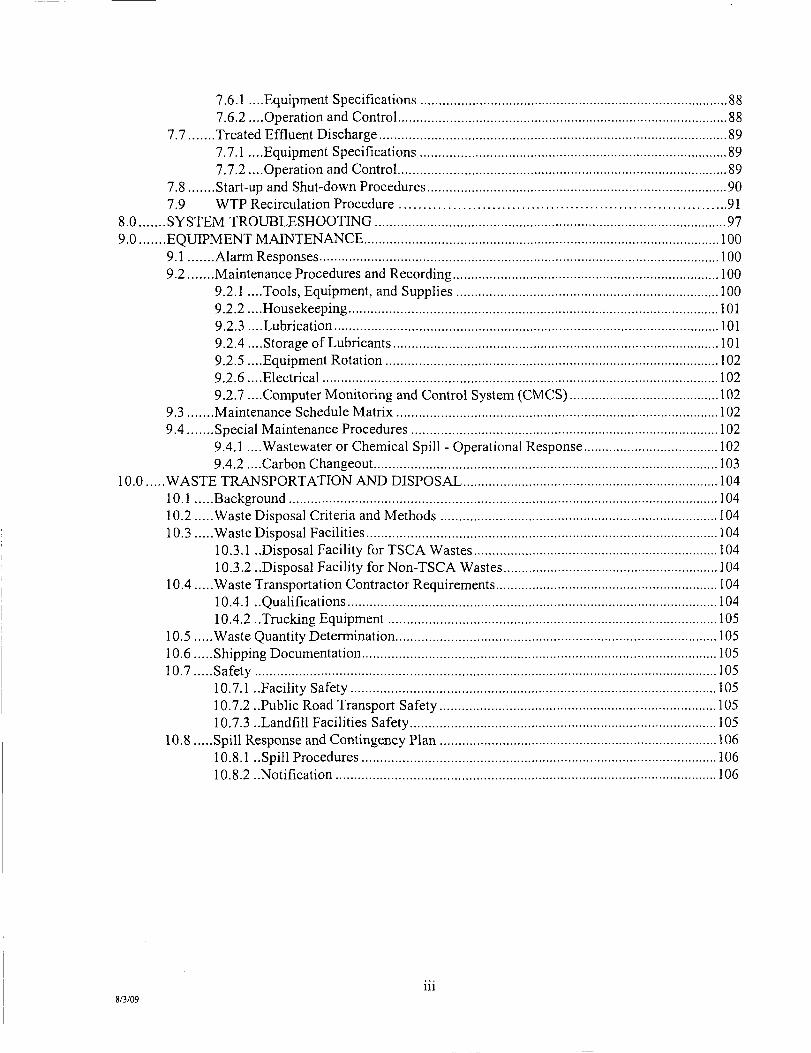
This document presents the Operation & Maintenance Plan (O&M Plan) for the Water Treatment Plant (WTP) for the remediation of polychlorinated biphenyls (PCBs) in Operable Units (OUs) 2 to 5 of the Lower Fox River and Green Bay Site (Site; Figure 1-1). The design of the WTP has been performed by Tetra Tech EC, Inc. (Tetra Tech), with support from various subcontractors. The equipment needed for the WTP has been provided by various subcontractors (TIGG Corporation, Cuno, Inc., Calgon Carbon Corporation, ModuTank Inc., and others). Dredging will be performed by J.F. Brennan (Brennan) and sediment desanding and dewatering (SDD) will be performed by Boskalis Dolman (Boskalis). The WTP operations will be conducted in the staging and material processing /water treatment building located on the former Shell property (see Figure 1 -2). The water that is generated by the sediment desanding and dewatering operations will be treated in the WTP to meet the discharge performance goals contained in the Design Report (Volume 1, Tetra Tech EC, Inc, et al, April 2009) before being returned to the Lower Fox River. The operation and maintenance procedures for the SDDP are not included in this document and are described separately in a companion document, the Operation & Maintenance Plan for the Sediment Desanding and Dewatering Plant.
The PCB cleanup remedy for the Lower Fox River was originally set forth in Records of Decision (RODs) for OUs 2 to 5 issued in December 2002 and June 2003 by the United States Environmental Protection Agency (USEPA) and the Wisconsin Department of Natural Resources (WDNR) under the authority of the Comprehensive Environmental Response, Compensation and Liability Act (CERCLA), as amended, 42 U.S.C. §§ 9601-9675. The RD requirements for OUs 2 to 5 (including this O&M Plan) were originally set forth in the Administrative Order on Consent (AOC) and associated Statement of Work (SOW) for OUs 2 to 5 (USEPA 2004), executed in March 2004 by Fort James Operating Company, Inc.' (Fort James) and NCR Corporation (NCR) (collectively the "RD Respondents") in cooperation with the USEPA and WDNR (collectively the "Response Agencies"). USEPA and WDNR are overseeing the RD process, and design documents prepared by the RD Respondents are subject to review and approval by USEPA and WDNR. In June 2007, a ROD Amendment was issued by USEPA and WDNR that made changes to parts of the remedy described in the original RODs in response to the new information analyzed in the Basis of Design Report (BODR), and also from experience with prior remediation activities at the Site (USEPA and WDNR 2007).
1.1 Purpose
This Operation and Maintenance (O&M) Plan was written to provide a generalized set of instructions of the methods and procedures required to maintain and operate the WTP at the site. This Plan includes information pertaining to the operation and maintenance of the facility, regulatory requirements for plant operation, management of plant records, qualifications of plant personnel, sampling and analysis requirements, health and safety procedures, and waste handling procedures.
This Plan is supplemented by equipment manufacturer O&M manuals for each equipment component. As the project progresses, additional equipment manufacturer O&M information may be added, as it is obtained. This Plan is to be treated as a living document that will require periodic updating as information and operational experience is obtained.
' In January 2007, Fort James Operating Company, Inc was converted to Georgia-Pacific Consumer Products LP.
1 8/3/09

o Legend / \ y USW:E CtwM MMBn
j / \ ^ AffWfcinTrtnemwfanCompiftifLh*
/ \ / IMniasiPlliMine J 2
I I rmOmtairaKi i j »
Figure 1-1 Lower Fox River and Green Bay Site
L o w r Fox RIvar OU 2-OU 5
II^ITITRAUCH

o It TETRA TECH EClhia
LOWER FOX RIVER SITE OPERABLE UNITS 2-5 GREEN BAY, WISCONSIN
SITE LOCATION MAP FIGURE 1
CAO FILE: FOX RIVER-IOCUS-AI.OWG

1.2 Organization of the O&M Plan
The purpose of this O&M Plan is to facilitate the understanding of key operations and maintenance features of this facility. The following gives a brief overview of the remaining sections of this O&M Plan.
• Section 2.0, Regulatory Compliance, outlines local, state and federal codes and regulations pertaining to the operation and maintenance of the WTP. Water quality performance standards using a zone of initial dilution (ZED) and discharge performance goals contained in the Design Report (Volume 1, Tetra Tech EC, Inc, et al, April 2009) that are necessary for the operation of the WTP outfall and diffuser and other operational requirements are contained in this section.
• Section 3.0, Records Management, describes record keeping forms and procedures for recording data from the operation and maintenance of the WTP. Samples of the required record keeping forms are contained in Appendix A, Report Forms.
• Section 4.0, Sampling and Analysis Plan Description, outlines the schedule and procedures for sampling and analyzing the various influent, intermediate, and effluent process streams associated with the operation of the WTP. Adherence to the quality standards and schedules for sampling and analysis described in this section are critical to the compliant, safe and efficient operation of the WTP.
• Section 5.0, Health and Safety, contains safety standards and procedures for all aspects of WTP operation and maintenance. This section along with the Health and Safety Plan must be consulted prior to the execution of any tasks performed by Operators and contractors to ensure they are performed in compliance with applicable safety procedures.
• Section 6.0, Process Description and Operation, describes the fiinctions and relationships of the major pieces of equipment in the nine process loops of the WTP. The Computer Monitoring and Control System (CMCS) programming is developed from these descriptions to ensure the process equipment functions properly with respect to the rest of the system. Manual and remote electronic controls and equipment interlocks are detailed in this section.
• Section 7.0, Operations, contains procedures for the daily operation of process equipment. Set points and ranges of operational parameters for normal function of the water treatment process are found in this section.
• Section 8.0, System Troubleshooting, highlights procedures for diagnosing and solving problems with the major pieces of equipment in the WTP. Additional troubleshooting information is also found in Appendix D, Manufacturer's Operation and Maintenance Manuals.
• Section 9.0, Equipment Maintenance, includes a matrix (under preparation) outlining the schedule and procedures for perfonning preventive maintenance on system equipment. This section also describes maintenance record keeping procedures and instructions for housekeeping and the general upkeep of the WTP.
4 8/3/09

• Section 10.0, Waste Transportation and Disposal, describes the requirements for on-site storage, marking, transportation, and disposal of all liquid and solid waste generated at the WTP. This section includes the requirements for selecting and approving subcontractors to handle and dispose of the waste generated at the facility, as well as record keeping requirements for waste generation and disposal.
1.3 Using the O&M Plan
The purpose of this O&M Plan is to facilitate the understanding of key operations and maintenance features of the WTP. A cursory review ofthis Plan by a new Operator will not qualify him/her to operate and maintain the Facility. Side-by-side training with an experienced Operator, a comprehensive review of this O&M Plan, and the appropriate State of Wisconsin Operator Certification are recommended to qualify a new Operator.
This O&M Plan should be updated periodically to remain current. The Plan should be revised when new and improved techniques are devised for operating and maintaining the WTP.
1.4 Site Location and Background
The Lower Fox River Site (CERCLIS ID # WIOOO1954841) as defined by the Response Agencies extends 39 miles from the outlet of Lake Winnebago to the mouth of the river where it discharges into Green Bay (Figure 1-1). The Lower Fox River is the most industrialized river in Wisconsin. Since the mid 1800s, water quality has been degraded by expanding industries and communities discharging sewage and industrial wastes into the river as well as by agricultural activity (USEPA and WDNR 2003). PCBs were discovered in the Lower Fox River in the 1970s. As set forth in the RODs, PCBs are the focus of current RD and RA efforts. The Neenah and Menasha Channels and Little Lake Butte des Mortes are sections of the Lower Fox River which are included in the Zone of Contamination (ZOC). This section of the Fox River includes what is considered the highest concentration of paper mills in the world, and also includes six publicly owned treatment works (POTWs). Approximately 270,000 people reside in the communities along the river. Although the river is no longer used for commercial shipping, twelve dams and locks are located on the Fox River near towns and industries. PCBs have been detected in both surface water and sediment throughout the Lower Fox River and Green Bay. Fishing is common throughout the Lower Fox River and Green Bay. Fish consumption advisories issued by WDNR are still in effect for many species in the Fox River, Green Bay and Lake Michigan.
L5 Description of OUs
The Lower Fox River is divided into five OUs: OU 1 is also known as Little Lake Butte des Morts. The Neenah and Menasha Dams control the pool elevation of Lake Wirmebago and the discharge to the upstream end of OU 1 at river mile (RM) 39. RD and RA activities in OU 1 are being addressed under a separate SOW and Consent Order.
. OU 2 extends from the Appleton Locks at RM 31.9 to the Little Rapids Dam at RM 13.1. This unit contains the majority of locks and dams in the Lower Fox River system and the greatest elevation drop and gradient. Sediments have a very patchy distribution in this reach with extensive intervening bedrock exposures. The OUs 1 to 2 ROD calls for active remediation in Deposit DD only, while monitored natural recovery (MNR) is the selected remedy for the remainder of OU 2. OU 3 extends from the Little Rapids Dam to the De Pere Dam al RM 7.1. Soft sediment covers most ofthis unit.
8/3/09

• OU 4 extends from the De Pere Dam to the river mouth at Green Bay. This OU contains a federal navigation channel, the northern portion of which is currently maintained by the U.S. Army Corps of Engineers (USAGE). The area around OU 4 is highly urbanized, and includes the City of Green Bay.
• OU 5 begins at the river mouth, and includes the entire bay of Green Bay, which is approximately 119 miles long and is an average of 23 miles wide (USEPA and WDNR 2003). The OUs 3 to 5 ROD specified MNR as the selected remedy for OU 5, with the exception of dredging and capping near the river mouth.
1.6 Project Overview and Objectives
In 2009, two 8-inch hydraulic dredges and one 12-inch hydraulic dredge will be used for removal of TSCA and non-TSCA sediments at OUs 2, 3, and 4. The dredges will remove the sediment to the neatline in OUs 2 and 3 and pump the material through the pipeline and accompanying floating booster stations to the upstream De Pere Dam easement, crossing into OU 4 on the parcel owned by USAGE between the De Pere Dam and lock and proceeding through OU 4 to the dewatering facility at the former Shell property staging and material processing facility. Mechanical dredging will be used as an option only if hydraulic dredging cannot be conducted in certain areas. The sand fraction of contaminated sediment that is removed from OUs 2 to 5 will be separated from the finer-grained dredge material, washed or otherwise treated as practicable, and beneficially reused to the extent feasible. The sediment will be processed through several stages to enable efficient and effective mechanical dewatering of the fines using membrane-type filter presses. The initial stages of desanding will include coarse debris separation, coarse and fine sand separation, and pre-thickening.
Superfund cleanups are required to meet the substantive discharge requirements of the Clean Water Act, but National Pollutant Discharge Elimination System (NPDES) permits are not required for on-site work. The water generated by dredging and SDDP operations will be treated prior to discharge back to the river and will meet.the discharge performance goals contained in the Design Report (Volume 1, Tetra Tech EC, Inc, et al, April 2009) The water treatment process will include multimedia sand filtration, bag filtration, cartridge filtration, and liquid-phase granulated activated carbon adsorption. Treated water will be sampled and analyzed to verify compliance with the water quality performance goals using a zone of initial dilution (ZID) and other substantive requirements necessary for the operation of the WTP outfall and diffuser
The primary objective of the WTP is to remove the suspended solids and dissolved phase PCBs. Other parameters such as biochemical oxygen demand (BOD), ammonia and low-level mercury from the wastewater may also be reduced before it is discharged back to the Lower Fox River. These parameters which are incidental to the treatment process will enable optimal performance of the dredge production rates and SDDP without interruption, and allow the achievement of planned remedial action goals of the amended ROD to be completed within 10 years.
1.7 General Description of WTP
The WTP will be housed at the former Shell property in a building adjacent to the SDDP (see Figure 1-3). Starting in 2009, contaminated sediment will be dredged by Brennan from the OUs 2-5 target areas using the two 8-inch hydraulic dredges Ashtabula and Palm Beach and the 12-inch hydraulic dredge Mark Anthony. The dredged sediment will be accompanied by river water and transported at a maximum rate of approximately 6,000 gallons per minute (gpm) to the SDDP via submerged 8-inch and 12-inch HDPE dredge material transfer pipelines. The estimated sustained maximum production rate for the two 8-inch hydraulic dredges operating at 65 percent uptime in OUs 2 and 3 and the 12-inch dredge operating at 80 percent uptime in OU 4(likely to be the maximum sustained uptime as per Brennan) will be
6 8/3/09

approximately 220 in situ cubic yards (cy) per hour. The solids content in the slurry is assumed to be approximately 9 to 11 percent by weight, but will likely fluctuate in the range of 5 to 15 percent by weight. The dredged material will initially be processed through coarse debris separation, coarse and fine sand separation, and pre-thickening, to enable subsequent mechanical dewatering of the fines using eight membrane filter presses.
Assumptions regarding dredging production rates and maximum flow rates to the SDDP were provided by Brennan and Boskalis, respectively. Maximum, average, and minimum production rates were also established in the Final Process Design Basis Technical Memorandum for Sediment Desanding and Dewatering System and Water Treatment System, dated March 30, 2009 (Process Design Technical Memorandum). A copy ofthis Technical Memorandum is presented in Appendix A. These production rates are 250 in situ cy per hour (short-term maximum), 220 in situ cy per hour (sustainable maximum), 150 in situ cy per hour (average required to meet targeted annual sediment removal rates), and 120 in situ cy per hour (short-term minimum). These production rates are equivalent to a solids content of approximately 9 to 11 percent by weight. These rates were developed based on the RD investigation samples and dewatering tests performed by press manufacturers Siemens Water Technologies (formerly U.S. Filter) in Holland, Michigan and Andritz in Arlington, Texas on the six composite sediment samples collected by Boskalis. The minimum production rate of 120 in-situ cy per hour anticipated for the dredges is based on minimum sediment transport velocity requirements for the HDPE pipelines.
The water treatment system has been designed to treat wastewater generated during the SDDP processes and with sufficient redundancy to allow those operations to continue uninterrupted. The WTP will operate continuously during dredging operations which are expected to be 24 hours/day, 5 days a week. If necessary, the treatment system will be capable of operating 24 hours/day, 7 days a week. The system is designed to continuously treat a maximum flow volume of 6,000 gpm but can efficiently operate at lower flow volumes expected to average 3, 500 to 4, 500 gpm depending upon dredging, desanding, and dewatering operations. As described in the Final Process Design Basis Technical Memorandum, a flow of 3,000 gpm is considered a minimum flow required to maintain suspension of silt and fine sand particles in the HDPE pipelines. The two 265,000-gallon water buffer tanks upstream of the water treatment system allow for balancing throughput with operations in the SDDP. The water treatment system will be staffed continuously during operation by trained and qualified wastewater treatment Operators.
From the water buffer tanks in the SDDP, the wastewater will be pumped in a once-through process through the water treatment system and into a 260,000 gallon effluent holding tank. The treatment system consists of the following processes:
• Twenty-four (24) 20,000 lbs. mixed media filtration vessels • Six (6) muhi bag filter vessels • Three (3) high flow cartridge filters; and • Eighteen (18) 20,000 lbs. granular activated carbon vessels.
The water treatment system has been generally arranged as three treatment trains. Individual vessels or entire treatment trains can be brought online or taken offline and isolated as needed depending on the flow volumes, contaminant concentrations and maintenance requirements. The twenty-four mixed media filtration vessels are operated in banks of four.
The system has been primarily designed as a suspended solids removal process reducing total suspended solids (TSS) from a peak concentration of 50 ppm to non-detectable levels. The system has been
8/3/09

^ •^*+++fH+H*t« t H W F+
100.6" [ 3 0 - 7 m l
\
'UMPS i» n ii i r
ADMINISTRATIVE AREA
=t=ir I— n—H.-ijim.,. -1711 ty=
OmCE/CONl«0 ' . ROOM
V
NOTE: CONTROL ROOM DOOSS AND WkDOWS ARE APPROX LOCATIONS ONLY ANO SHALL QE ACCURATELY L O C A T E D * FIELD FIT DURING CONSTRUCTION.
-It. s u e ?iptHc
I 9 I I X 9 I X 0)
AIR C O y p R E S S O R —
HLfLTIB<lC DLTtftS
©-^^0 0 <4) <& Tr Tr ^T ^^ ^T^ TT
B
COWCRHE P A D (TtP.)
X aOOR DWW (TTr)
Cfi
CFB
ACTIVATCD CARBON
CAC *P5PRBEB5
xr XT
, : ^
ptWERW. MOTE:
AIL 04FOilMA'nON/ini(ENSK>HS ON THIS DRAMMG MIAT BE HEW VERtFia> FOR OOHSTRUCnm TWT HAS ALAEADT OCCURED. OR CHECKED AGAmET SHOP DRAWN59.
ISSUED FOR REFERENCE ONLY
IK'S auwiHC PKo-jzeo M JtUTOCID
0 0 HOT REVISE bANUAU.v
IW5 KCkMin « I>« PWWtPf
or w t a ro* xMR n r cMur
(ittc). 4ffD e nmocD j f v . i t t Ca«r>3N IWT IT a u lOT u KtMOCUCa, C3MB. n BSJCS ^ It n v 7 rf*rt: n s PMWOED OtOM. HttHKO VUVOSt 'VQ scuLT r m T>c acnmav c* Mtmr y T.<t O O t D t a c M Q
f . VW
III
z§
I S i
®
Ul z
a. o O S ^^.
Ul & > UJ
s u. K Ul
B . 3 O
CO
a- S DC o
K i Ul
il
a z
I! £^
P K O en Ik i 0. z
3 CO
3 Q.
K Z U l
I i
FIGURE 1-3

designed to backwash each mixed media filter vessel up to once a day. The filtration system will accept and effectively treat variable TSS influent concentrations. PCBs and mercury are strongly associated with the suspended solids and will be substantially removed in conjunction with the suspended solids. Any remaining dissolved-phase PCBs will be removed by the activated carbon. The activated carbon may also have an affinity for mercury and BOD as well. The activated carbon vessels will be arranged in series with half of the vessels serving as primary or "lead" vessels and the other half as secondary or "lag" vessels so that any break- through of PCBs or other monitored contaminants can be detected during routine sampling at the mid-point between the primary and secondary carbon vessels. Change-out of the primary carbon vessels will be initiated when break-through is detected at the mid-point. Once changed out, these vessels will become the new secondary vessels while the old secondary vessels are placed in the primary position.
1.7.1 Water Treatment Svstem Overview
A Process Flow Diagram is presented on Figure 1-4, and illustrates the design flow rates through the water treatment process. This drawing also includes the WTP mass balance and identifies the discharge performance goals. The treatment process includes multimedia sand filtration, bag filtration, cartridge filtration, and GAC adsorption. The cartridge filtration has the flexibility to be operated in two modes: 1) upstream of the GAC adsorption to enhance the solids filtration and further protect the carbon vessels from solids loading; or 2) downstream of the GAC adsorption to prevent the discharge of carbon fines to the effluent flow. Water treatment will be performed through a two-stage pumping process. The first stage is from the SDDP system water buffer tanks; through the multimedia, bag, and cartridge filtration as well as the GAC adsorption; into an intermediary effluent holding tank. The second pumping stage is from the effluent holding tank through discharge piping into a multi-port diffuser located in OU 4 approximately 500 linear feet from the former Shell property shoreline. All piping in the first pumping stage will be standard wall thickness carbon steel. Piping in the second stage will be predominantly HDPE.
1.7.1.1 Design Flow and Influent Concentration The water treatment system has been designed to process a peak flow of 6,000 gpm and a peak TSS concentration of 50 ppm. The average flow rate is estimated to be approximately 4,500 gpm and the minimum flow rate is estimated to be approximately 3,000 gpm. These maximum, average, and minimum flow rates are the same as the maximum, average, and minimum flow rates planned for the SDDP, as described above. Although flows will be added (through intemal loops, etc.) from filter backwash and cleaning activities, these flows will be routed to the overflow tank and added gradually into the flow entering the SDDP. Some flow will also be lost as moisture content in the filter cake and sand. In addition, extra process pumps and process vessels have been included in the design to provide reserve capacity should any pumps or vessels need to be taken offline for maintenance.
1.7.1.2 Water Transfer from Dewatering System The water treatment system begins at the main process pumps. These pumps will be housed in the SDDP so that their location will be in close proximity to the water buffer tanks located within the SDDP. The two water buffer tanks are part of the SDDP design. The WTP will have a dedicated level control system within one of the water buffer tanks to control the main process pumps. In addition, to prevent water buffer tank overflow, the SDDP system will also have an independent level alarm acting as an interlock to the SDDP process should the water buffer tank being pumped from ever reach a high-high level condition.
The main process pumps will consist of three 200-hp Gorman Rupp end suction centrifugal pumps each capable of 3,000 to 4,000 gpm. Each pump motor will be controlled by an interconnected variable frequency drive (VFD). Under normal operating conditions, two pumps will be kept running (each
9 8/3/09

TETRATECH \ / A N C H O R V k a ? NVIRONMCNTItL. L.L.C.
10
Figure 1-4 Process Flow Diagram of Water Treatment System
Lower Fox River - OUs 2 to 5

handling 50 percent of the desired flow) and the motor speed will be controlled to maintain a pre-set low level (selected by the Operator) within the water buffer tanks. A minimum effluent discharge flow rate of 3,000 gpm will be maintained at all times. The VFDs will be linked so that both pumps will be mn at the same speed when in parallel operation. The pumps will be operated in this manner for flows up to 6,000 gpm.
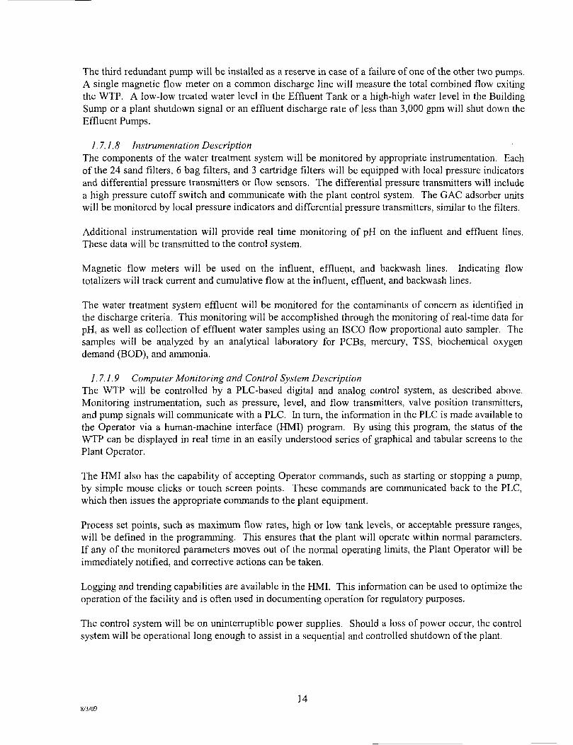
The third redundant pump will be installed as a reserve in case of a failure of one of the other two pumps. A single magnetic flow meter on a common discharge line will measure the total combined flow into the WTP.
1.7.1.3 Multimedia Sand Filtration Sand filtration will consist of (24) 8-foot-diameter vessels with an approximate media capacity of 20,000 pounds and a cross-sectional area of 50 square feet. These vessels are TIGG Model C-500. The fdter vessels will each contain four filter media including, gravel, garnet, sand, and anthracite, which will result in approximately 5-micron nominal filtration efficiency. The multiple filter media within each vessel have varying gradations in particle size that allow for greater depth of filtration through the filter bed and increase the amount of operating time between backwash events. As described in the process flow description for the SDDP, water exiting the pre-thickener tanks will have a maximum TSS load of 50 mg/1.
These vessels will be laid out in three treatment trains of eight vessels per train. Piping and valving will be arranged to allow as few or as many vessels to be online at one time. A complete treatment train can be isolated and kept in reserve or each bank of four vessels can be isolated as needed.
The maximum hydraulic capacity of the sand vessels will be 400 gpm each. At 6,000 gpm and 16 vessels online, the filtration rate is a maximum of 7.5 gpm per square foot, which is consistent with standard practice and within the hydraulic capacity of these vessels. Placing more vessels online (up to a total of 24) will result in increased efficiency (to 5 gpm per square foot), less frequent backwash, and reduced head loss.
Backwash of the multi-media sand filters will be performed one vessel at a time, in a sequential manner, based on differential pressure across the filters. Each filter vessel will be equipped with a flow sensor that will detect a reduction of flow as the solids loading on the vessel increases. The differential pressure across all of the multi-media filter vessels will also be continuously monitored. Backwash supply water will be pumped from the effluent tank using dedicated backwash pumps at approximately 20 gpm per square foot, equivalent to 1,000 gpm. Initially, however, a lower backwash rate of about 600 gpm has been effective. Extended usage of the multi-media filter vessels may result in the need for a 720 to 780 gpm rate as recommended by the manufacturer in the future. A typical backwash is 10 to 22 minutes per vessel. Valves on the multi-media filter vessels will be automatic, air-actuated type. Alternatively, the Plant Operator can manually initiate a backwash operation from the system PLC. Backwash water will be returned to the overflow tank in the dewatering facility for fiirther processing.
1.7.1.4 Bag Filtration Bag filtration will consist of six multi-bag fiUer vessels. Each vessel will contain 12 individual bag filters. These vessels will be Cuno Model No. 12 ME. Bag filter efficiency rating will be 10 micron nominal or less. Actual efficiency rating of the bag filters will be determined in the field to balance maximum filter efficiency with a reasonable operation and maintenance time for filter change-out. The multi-bag filter vessels will be arranged in three treatment trains of two vessels each. Piping and valving will be arranged to allow any number of vessels to be operated simultaneously. An entire treatment train can be isolated and kept in reserve, or individual vessels can be isolated as needed.
11 8/3/09

The maximum hydraulic capacity of each multi-bag filter vessel is 1,750 gpm. Under normal operations, at least one of the six vessels will be offline for filter change-out. The differential pressure across all of the multi-bag filter vessels will also be continuously monitored. When indicated by a high differential pressure in any of the online vessels, a switch will be made to place the offline vessel with clean bag filters into operation and take the vessel with spent bag filters out of operation, allowing for bag change-out. This will be a manual vessel switchover initiated by the Operator; however, a high differential pressure switch across all vessels will activate an annunciator on the PLC to notify the Operator that a switch over is required.
1.7.1.5 Cartridge Filtration Cartridge filtration will consist of three high-flow cartridge filter vessels. Each vessel will contain 12 individual cartridge filters. These vessels will be Cuno Model No. 12HF60HBFD. Cartridge filter efficiency ratings will range from 1 to 70 microns, absolute. Actual efficiency ratings of the cartridge filters will be determined in the field to balance maximum cartridge filter efficiency with a reasonable operation and maintenance time for filter change-out.
The cartridge filter vessels will be arranged in three treatment trains of one vessel each. Each vessel will be rated for a maximum hydraulic flow of at least 3,500 gpm. Any number of cartridge filter vessels can be operated simultaneously, or individual filter vessels can be isolated as needed. In addition, piping and valving will be arranged to allow the cartridge filters to be operated either upstream or downstream of the activated carbon adsorbers.
Under normal operations, at least one of the three vessels will be offline for filter change-out. The differential pressure across all of the cartridge filter vessels will also be continuously monitored. When indicated by a high differential pressure in any online cartridge filter vessel, a manual switch will be implemented to put the offline vessel with new cartridge filters into operation and take the vessel with spent cartridge filters out of operation for change-out. This will be a manual vessel switchover initiated by the Operator; however, a high differential pressure switch across all vessels will activate an annunciator on the PLC to notify the Operator that a switchover is required.
1.7.1.6 Granular Activated Carbon Adsorption The activated carbon process will consist of nine dual-unit carbon adsorbers. Each dual-unit carbon adsorber consists of two vessels containing 20,000 pounds of carbon each and can be operated in parallel or series. Each dual-unit is rated for a maximum hydraulic capacity of 1,400 gpm in parallel or 700 gpm in series. The empty bed contact time is approximately 8 minutes in the primary vessels and 16 minutes overall (both primary and secondary vessels) at 6,000 gpm.
Series Operation The carbon adsorption system has been sized to run in series at the peak design flow rate of 6,000 gpm. Series operation has the advantage of being able to monitor for breakthrough of contaminants at the midpoint between the primary and secondary vessels. In the case of breakthrough of the primary carbon vessel, the breakthrough will be detected and a change-out of the primary carbon vessel can be initiated. Contaminants that break through the primary vessel will be captured on the secondary vessel instead of being discharged to the river. Initial carbon breakthrough sampling will be perfomied on a monthly basis. This frequency may be adjusted during operations to optimize performance monitoring. Carbon breakthrough sampling will include, at a minimum, grab samples at the carbon influent and in between series carbon vessels. At the expected low levels of PCB concentrations in the water, usefial life for each of the carbon adsorber vessels is several years. It is possible, however, that other constituents in the water may affect the time to breakthrough. Sampling will be conducted at the vessel pair which has the greatest operation online time and/or greatest total flow. Additional vessel pairs may be sampled if deemed
12 8/3/09

necessary. Carbon adsorber vessels in series will be switched from upstream to downstream posidon when the PCB level in between is approximately half of the typical PCB concentration in the influent water.
At the peak design flow of 6,000 gpm, all nine dual units can be operated in series. At lower flows, units can be taken offline and put into reserve, or alternatively all nine dual units can be operated at lower flow rates, increasing the contact time and performance.
Backwash The carbon adsorbers will be piped and valved to allow the vessels to be manually backwashed if it becomes necessary due to solids loading. Differential pressure will be measured at each carbon vessel, and a high differential pressure switch will activate an annunciator on the PLC to notify the Operator that a backwash is required. When indicated by a high differential pressure in any carbon vessel, the Operator will manually switch the valving and operate the backwash pump to initiate a backwash. Backwash water from sand filters and from granular, activated carbon units will be returned to the overflow tank in the dewatering plant for gradual feed into the residue tank. The design daily backwash of 16 sand fihers at 600 to 1,000 gpm for 10 to 22 minutes each and weekly backwash of twelve of the carbon vessels at 1,000 gpm for 10 to 22 minutes each has been included in the design and added to the Process Flow Diagrams for the WTP and the SDDP. Solids in the backwash water will be removed in the SDDP, and the water will be returned to the WTP for treatment.
Carbon Change-out If it becomes necessary, carbon change-out can be conducted using either dry carbon delivered in 1,100-pound super sacks or by means of carbon/water slurry delivered in a 20,000-pound load by a tractor trailer unit. The layout of the carbon vessels has been designed so that a tractor trailer unit can approach to within 20 feet or less of each dual carbon vessel unit. Using the carbon slurry method, pressurized air will be used to push the spent carbon out of the vessel and into a waiting empty tractor trailer unit for off-site regeneration or disposal. New or regenerated carbon from a second tractor trailer will then immediately be transferred into the empty carbon vessel.
1.7.1.7 Effluent Tanks, Effluent Pumps and Discharge Diffuser Subsequent to filtration and carbon adsorption, the treated water will enter a 260,000-gallon effluent holding tank. The effluent holding tank will be a Modutank Model MS4920 ModuStor or equivalent and will be an approximately 49-foot-diameter by 20-foot-high bolted steel tank with a 45 mil polypropylene reinforced liner. The tank will be housed inside the WTP building.
Treated water will be pumped from the effluent holding tank into an 18-inch-diameter HDPE discharge line where it will be transported approximately 2,000 feet to a submerged multi-port diffuser for discharge into OU 4 of the Lower Fox River. During operation, a minimum flow of 3,000 gpm will be maintained so that a velocity of 10 ft/sec can be achieved at the diffuser ports.
Discharge pumping will be performed by three Cornell 30-hp (Model 10RB-F18DB) end sucfion centrifugal pumps each capable of 3,000 gpm. Each pump motor will be controlled by an interconnected variable frequency drive (VFD). Under normal operating conditions, two pumps will be kept running (each handling 50 percent of the desired flow) and the motor speed will be controlled to maintain a preset low level within the effluent tank. A minimum flow rate of 3,000 gpm will be maintained at all times. The VFDs will be linked so that both pumps will be run at the same speed when in parallel operation. The pumps will be operated in this manner for flows up to 6,000 gpm.
13 8/3/09
The third redundant pump will be installed as a reserve in case of a failure of one of the other two pumps. A single magnetic flow meter on a common discharge line will measure the total combined flow exiting the WTP. A low-low treated water level in the Effluent Tank or a high-high water level in the Building Sump or a plant shutdown signal or an effluent discharge rate of less than 3,000 gpm will shut down the Effluent Pumps.
7.7.7.5 Instrumentation Description The components of the water treatment system will be monitored by appropriate instmmentation. Each of the 24 sand filters, 6 bag filters, and 3 cartridge filters will be equipped with local pressure indicators and differential pressure transmitters or flow sensors. The differential pressure transmitters will include a high pressure cutoff switch and communicate with the plant control system. The GAC adsorber units will be monitored by local pressure indicators and differential pressure transmitters, similar to the filters.
Additional instmmentation will provide real time monitoring of pH on the influent and effluent lines. These data will be transmitted to the control system.
Magnetic flow meters will be used on the influent, effluent, and backwash lines. Indicating flow totalizers will track current and cumulative flow at the influent, effluent, and backwash lines.
The water treatment system effluent will be monitored for the contaminants of concem as identified in the discharge criteria. This monitoring will be accomplished through the monitoring of real-time data for pH, as well as collection of effluent water samples using an ISCO flow proportional auto sampler. The samples will be analyzed by an analytical laboratory for PCBs, mercury, TSS, biochemical oxygen demand (BOD), and ammonia.
7.7.1.9 Computer Monitoring and Control System Description The WTP will be controlled by a PLC-based digital and analog control system, as described above. Monitoring instmmentation, such as pressure, level, and flow transmitters, valve position transmitters, and pump signals will communicate with a PLC. In turn, the information in the PLC is made available to the Operator via a human-machine interface (HMl) program. By using this program, the status of the WTP can be displayed in real time in an easily understood series of graphical and tabular screens to the Plant Operator.
The HMl also has the capability of accepting Operator commands, such as starting or stopping a pump, by simple mouse clicks or touch screen points. These commands are communicated back to the PLC, which then issues the appropriate commands to the plant equipment.
Process set points, such as maximum flow rates, high or low tank levels, or acceptable pressure ranges, will be defined in the programming. This ensures that the plant will operate within normal parameters. If any of the monitored parameters moves out of the normal operating limits, the Plant Operator will be immediately notified, and corrective actions can be taken.
Logging and trending capabilities are available in the HMl. This infomiation can be used to optimize the operation of the facility and is often used in documenting operation for regulatory purposes.
The control system will be on unintermptible power supplies. Should a loss of power occur, the control system will be operational long enough to assist in a sequential and controlled shutdown of the plant.
14 8/3/09

1.8 Staffing and Training
1.8.1 Staffing
The WTP will be staffed by Operators who are certified under the requirements of WDNR Chapter NR 114 of the Wisconsin Administrative Code.
There will be at least one certified Operator on duty at the WTP, 24 hours per day, five days per week. Two 12-hour sliifts are plarmed for each day. Multiple management staff will also obtain WTP Operator certifications to support operations. Emergency or back-up personnel will be available as required to support repair or complex maintenance activities. Technical support and altemate Operators will be provided by specialty subcontractors for operational or equipment problems of a technical nature and additional operations support. For example, a local l&C/electrical subcontractor may be retained to troubleshoot and repair the PLC quickly, in the event problems are experienced.
Monitoring of the WTP required by WDNR and USEPA for compliance with the Consent Decree will be carried out under the direction of registered Professional Engineers.
A contracted maintenance crew or authorized equipment service representatives will perform repairs of mechanical/electrical equipment which are in excess of the Operator's capabilities.
1.8.2 Training
The Operator will be required to participate in a field training program given by Tetra Tech and selected equipment manufacturer representatives. The training will address equipment operation, maintenance, equipment, safety requirements and troubleshooting and other subjects required to properly operate the WTP including regular communication with the Site management, the dredging operation, and the SDDP.
The Operator will also comply with the requirements of WDNR Chapter NR 114 of the Wisconsin Administrative Code.
1.9 Supporting Documentation
The following supporting documents and manual have been used as technical references for this Operations and Maintenance Manual:
1. 100 Percent Design Report for 2009 Remedial Action, Volume 1, April, 2009, by Tetra Tech et al.
2. Final Process Design Basis Technical Memorandum for Sediment Desanding and Dewatering System and Water Treatment System, March 30, 2009, by Tetra Tech EC
3. O&M Manuals, Appendix D (Manufacturers' Operation & Maintenance Manuals) 4. Water Treatment Plant Design Drawings and Specifications October 31, 2008, by Tetra
Tech EC
15 8/3/09
2.0 REGULATORY COMPLIANCE
This section of the Operation and Maintenance Manual identifies the Federal, State and local regulations that are applicable to the operation of the WTP. The applicable regulations have been summarized relative to the following activities:
• Discharge of Treated Water • Waste Storage, Transportation and Disposal (spent granular activated carbon, spent bag
filters, spent cartridge filters, personal protective equipment [PPE])
The specific regulations are identified below. The agency names, addresses and telephone numbers are provided for reference.
2.1 Discharge of Treated Water (Effluent)
In 1972, the United States Congress: passed the Federal Water Pollution Control Act Amendments of 1972 (Public Law 92-500). Federal water quality regulations are found in Title 40 of the Code of Federal Regulations. This law authorized the Federal Government through USEPA to assume the dominant role in directing and defining a national program for water pollution control. The law also authorized EPA to delegate certain responsibilities to any state that could demonstrate the necessary levels of expertise and authority to administer the program. Wisconsin obtained EPA delegation on Febmary 4, 1974.
The Wisconsin Pollutant Discharge Elimination System (WPDES) permit program was established by Chapter 283.13(1), Wisconsin Statutes. State wastewater regulations are found in Wisconsin Administrative Code Chapters 100-299 and Wisconsin State Laws and Statutes.
In Wisconsin, WPDES permits are issued by the WDNR's Bureau of Watershed Management, with federal oversight from the USEPA. The permit program is administered by the Department, with the Office of the Attomey General providing legal resources for the Department in enforcement activities. The Department is responsible for the issuance, reissuance, modification, and enforcement of all WPDES permits issued for discharges into the waters of Wisconsin (except discharges occurring on Native American lands which are regulated directly by EPA). Wisconsin regulates discharges to both groundwater and surface water; EPA only requires regulation of surface water discharges. No person may legally discharge to waters of the state without a permit issued under this authority.
Wastewater treatment plant plan review authority exists in s. 281.41, Wisconsin Statutes. This authority results in the required review of municipal and industrial treatment plant constmction plans as well as related monitoring systems and groundwater monitoring wells.
2.1.1 histallation of WTP Outfall A wastewater treatment system HDPE outfall has been designed as described below, and will be constmcted in winter 2008 or spring 2009 to discharge treated wastewater generated from sediment dewatering and water treatment operations in OUs 2 to 5. The outfall includes discharge piping with a diffuser assembly designed to achieve the necessary initial dilution to comply with water quality performance standards using a ZID as defined by the State regulations, which allows the use of Best Demonstrated Treatment Technology Reasonably Achievable (BDTTRA). The projected performance of the difftiser was modeled using EPA UDKHDEN software. The WTP outfall will be operated to meet the discharge perfonnance goals contained in the Design Report (Volume 1, Tetra Tech EC, Inc, et al, April 2009).
16 8/3/09
Physical Location The treated effluent outfall HDPE pipeline will mn at grade from the WTP at the former Shell property staging and material processing facility eastward generally along the south side of the property to near the shoreline and then mn southeast to a point north of the railroad trestle before tuming east and entering the Fox River. The river portion of the effluent piping will be pre-fabricated on-site, including the multiport diffuser at the end of the pipe for installation. The temporary diffuser will be placed above the river bottom. The pipe and diffiiser will be weighted with concrete collars to overcome buoyancy and maintain alignment. At the location where the outfall pipe enters the river, a ground cover thicker than the freeze level may be maintained to protect the pipe. Figure 2-1 shows the approximate location of the outfall line from the former Shell property and where it enters OU 4. Both the pipeline route in the river and the design of the diffiiser have been finalized and are included in the Effluent Discharge Design Technical Memorandum (Attachment A-6) in Volume 1 of the Design Report, which includes the EPA UDKHDEN modeling.
Monitoring of Compliance with Discharge Performance Goals A discharge monitoring location has been established prior to the effluent water discharge into the Lower Fox River to facilitate sampling to monitor for compliance with the discharge performance goals established for OUs 2 to 5 and approved by the Response Agencies via submittal of the Process Design Basis Technical Memorandum. These data will be obtained according to the frequency described in the Technical Memorandum and reported to the Response Agencies. Operational responsibilities include monitoring of the discharge for pollutants specified in the discharge performance goals, monitoring of the fiow rate of effluent discharged, preparation of Discharge Monitoring Reports for submittal to WDNR, and self-notification of any discharge goal exceedances to WDNR in a timely manner.
2.1.2 Effluent Water Qualitv Discharge Performance Goals
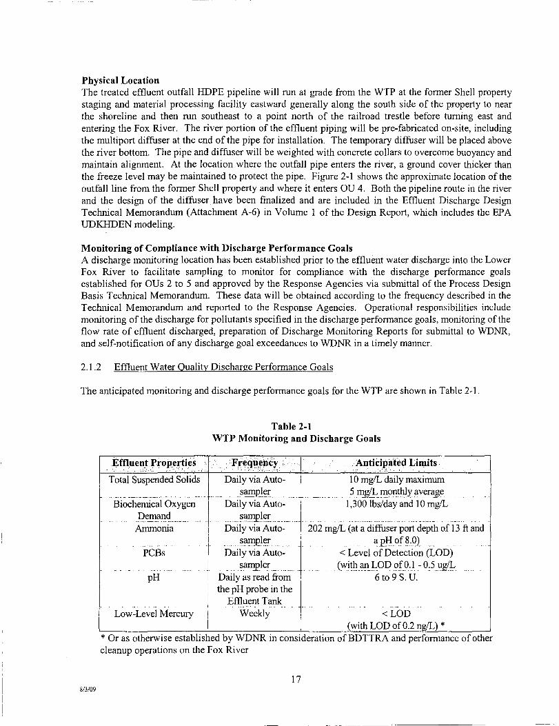
The anticipated monitoring and discharge performance goals for the WTP are shown in Table 2-1.
Table 2-1 WTP Monitoring and Discbarge Goals
Effluent Properties
Total Suspended Solids
Biochemical Oxygen Demand
Ammonia
PCBs
p H
Low-Level Mercury
• ^Frecjuehcy ;;••;:'•• •..
Daily via Auto-sampler
Daily via Auto-sampler
Daily via Auto-sampler
Daily via Auto-sarnpler
Daily as read from the pH probe in the
Effluent Tank Weeidy
Anticipated Limits
10 mg/L daily maximum 5 mg/L monthly average
1,300 lbs/day and 10 mg/L
202 mgT. (at a diffiiser port depth of 13 ft and a pH of 8.02
< Level of Detection (LOD) (withanLODof0.1-0.5ug/L
6to9S.U.
<LbD (with LOD of 0.2 ng/L) *
* Or as otherwise established by WDNR in consideration of BDTTRA and performance of other cleanup operations on the Fox River
17 8/3/09

o
NOTE;
1.) UPDATED SFTE SURVEYED PEFtPOnieO BY STS (AECOU) ON la-W-SOOB.
?.] COrfTOLRS COf#>ll£0 FROM SHE SURVEYS. HISTORICAL SURVEYS PEfVOWCO BV STS CONSULTANTS AND OB CCWTOUBS DATA FROM BRCNVM COUNTY. VflSCOHSIN.
3.) HORL^m I AL corn KOL HtN:HbNCtU> WISCONSIN 81AI b HIAM^. CtN I HAL £ONt <4tXr4 (US SUm« FEET) COORDINATES tN RELATION TO n C NORTH AMERICAN DATUM OF 19S3 <1997) NAD 83 (07).
4.) ElfVATIONS ARE REFER&JCED TO NORTH AMERICAN VERTiCAt DATUM 1»8 (NA\^»S).
S.) SOME SrTE FEATURES ARE NOT SHOIW FOR CUWFTY.
6 REFERENCE PND' STStAECOM) ORAWROS FOR BULKHEAD WAU
r.) FOUOMflMC MSTALLATION OF WCK DRAMS. INSTALL WCK DRANAOE LAYER FROM ElEVATIOtO STT TO S?9 FEET NAVO « , IM At^WttJAhCE WTTH THE REFERENCED DESGN ORAWtrtSS BY PHtt STS
(AECOM).
HOWTM U »
DRAFT
STS AECOM
D20.468.197S www.st£.aecom xom CcwV« €)2D«. B»;Bt8
z CL z o
i i z z ^ ^
< UJ t?
o ss X _ i r j m o> o o CM
6 (f>
x $
t u UJ K a:
O
Dfawn: 0TB 12/11/2008
Ctwcusd: MJM 12/11/2008
Approyed: JMT 12 /11 /20 (»
200801978
rKnME NUMKR 0-3
TETRATECH t / A N C H O R ^ W ^ ^ E N V I R O N M E N T A L , L . L - C .
18
Figure 2-1 Former Shell Property Site Development Plan
Lower Fox River - OUs 2 to 5

Agency Contacts Information:
• NR 157 - WDNR Management of PCBs, NR 500 series codes
Wisconsin Department of Natural Resources
Mr. Jim Zellmer Northeast Region Headquarters
2984 Shawano Avenue Green Bay, Wl 54313
(920)662-5431
or 49 CFR 100-180 - Transportation
U.S.Department of Transportation Pipeline and Hazardous Materials Safety Administration
Central Region Office 2300 East Devon Avenue, Suite 478
Des Plaines,IL 60018 (847) 294-8580
or U.S.Department of Transportation
Pipeline and Hazardous Materials Safety Administration East Building, 2"'' floor
1200 New Jersey Avenue, SE Washington, D.C. 20590
(202) 366-0656
or
DOT Hazardous Materials hiformation Center: (800) 467-4922
20 8/3/09
Agency Contacts Information:
• Effluent Discharge Analytical Test Methods and WPDES Permit Requirements
Wisconsin Department of Natural Resources
Mr. Gary Kincaid Northeast Region Headquarters
2984 Shawano Avenue Green Bay, Wl 54313
(920)662-5136
or
Wisconsin Department of Natural Resources Mr. Bruce Baker, Implementation Coordinator
Bureau of Watershed Management 101 S.Webster Street Madison, Wl 53703
(608) 267-9352
2.2 Waste Storage, Transportation and Disposal
Storage of waste on-site will consist of spent multi-media materials, spent granular activated carbon, spent cartridge filters, spent bag filters and used personal protective equipment (PPE). These waste streams will be appropriately characterized (profiled) prior to disposal, as described in Sections 4 and 10. It is anticipated that the wastes generated will be non-hazardous. The wastes will be manifested as either non-hazardous/non-TSCA waste or as TSCA waste depending on the waste profile, for offsite transportation and appropriate disposal. It is planned that non-hazardous wastes will be transported via trucks and disposed of at the Veolia Hickory Meadows Landfill near Hilbert, Wisconsin. It is planned that TSCA wastes will be transported via trucks and disposed of at the EQ Wayne Disposal Inc. Landfill in Belleville, Michigan.
When necessary, carbon change-out can be conducted using either dry carbon delivered in 1,100-pound super sacks or by means of carbon/water slurry delivered in a 20,000-pound load by a tractor trailer unit. The layout of the carbon vessels has been designed so that a tractor trailer unit can approach to within 20 feet or less of each dual carbon vessel unit. Using the carbon slurry method, pressurized air will be used to push the spent carbon out of the vessel and into a waiting empty tractor trailer unit for off-site regeneration or disposal. New or regenerated carbon from a second tractor trailer can then immediately be transferred into the empty carbon vessel.
19 8/3/09

3.0 RECORDS MANAGEMENT
3.1 Introduction
A comprehensive Records Management Program is essential to the efficient operation of the WTP. Information relative to: facility usage, equipment preventative maintenance, sampling analysis and monitoring, process control monitoring, bench scale test results, chemical usage, personnel management, etc. must be collected by the Plant Operator and reported upon request to meet regulatory and client requirements. This Section briefly summarizes the recommended records management program for the Lower Fox River Site Water Treatment Plant.
In accordance with the requirements of the client contract and the requirements of the AOC, a bound operation and maintenance log and an electronic log is to be maintained by the Operator on-site, to include all collected records and events as described in this Section.
3.2 Process Control Recording
Process control recording is to be completed by the Operator on a daily basis. It is divided into two categories: 1) process monitoring via the Computer Monitoring and Control System (CMCS) and 2) equipment operation monitoring via manual/visual inspections.
3.2.1 Process Monitoring
Process control data will be transmitted from the instrumentation to the CMCS system. The Operator will download selected process control data into a daily report. Infomiation that is not directly available from the CMCS will be manually recorded by the Operator. Tables 3-1 and 3-2, CMCS Monitoring, include a listing of systems that are to be monitored by the CMCS.
The process monitoring reports will include at a minimum the following information:
Total daily flow and average daily flow rate of wastewater pumped to the WTP (from CMCS);
Total suspended solids content of wastewater pumped to the WTP (from laboratory analysis);
Concentrations of PCBs, ammonia, BOD, mercury, and pH of wastewater pumped to the WTP (pH from CMCS, PCBs, ammonia, BOD, and mercury from laboratory analysis);
Identification of any multimedia sand filters that were backwashed (from CMCS);
Total daily volume of backwash water pumped through the muhimedia sand fihers and/or the carbon adsorbers, if applicable (from CMCS);
Identification of any carbon adsorbers that were backwashed (from Operator records);
Identification of the carbon adsorbers that were switched from secondary to primary (from Operator records);
8/3/09 21
Identification of the carbon adsorbers that were charged with fresh carbon (from Operator records);
Identification of the multi-bag filter vessels in which spent bag filters were replaced (from Operator records);
Identification of the cartridge filter vessels in which spent cartridge filters were replaced (from Operator records);
Total suspended solids concentration of treated effluent wastewater pumped to the diffuser in the river (from laboratory analysis);
Concentrations of PCBs, ammonia, BOD, mercury, and pH of treated effluent wastewater pumped to the diffuser in the river in accordance with the established sampling frequency (pH from CMCS, PCBs, ammonia, BOD, and mercury from laboratory analysis);
Total daily flow quantity and average daily flow rate of treated effluent wastewater pumped to the diffuser in the river (from CMCS);
Daily recording of maintenance and repairs made to equipment (from Operator records); and
Daily recording of instrument alarms and process control system upsets (from CMCS).
This information will be made available through summarized spreadsheets via the CMCS software program. Based on experience gained in operating the WTP, following the start-up and prove-out periods as discussed in Section 4.3.1, Tetra Tech may reduce the frequency of sampling and analyses for the influent wastewater.
During 2009, the operation of the various subsystems of the WTP will be monitored and the data collected will be utilized to conduct value engineering studies in order to determine how the WTP process can be optimized and/or modified to improve the efficiency and reduce operating costs. Depending on the results of these studies, the operation of the WTP may be modified for 2010 and later years.
22 8/3/09
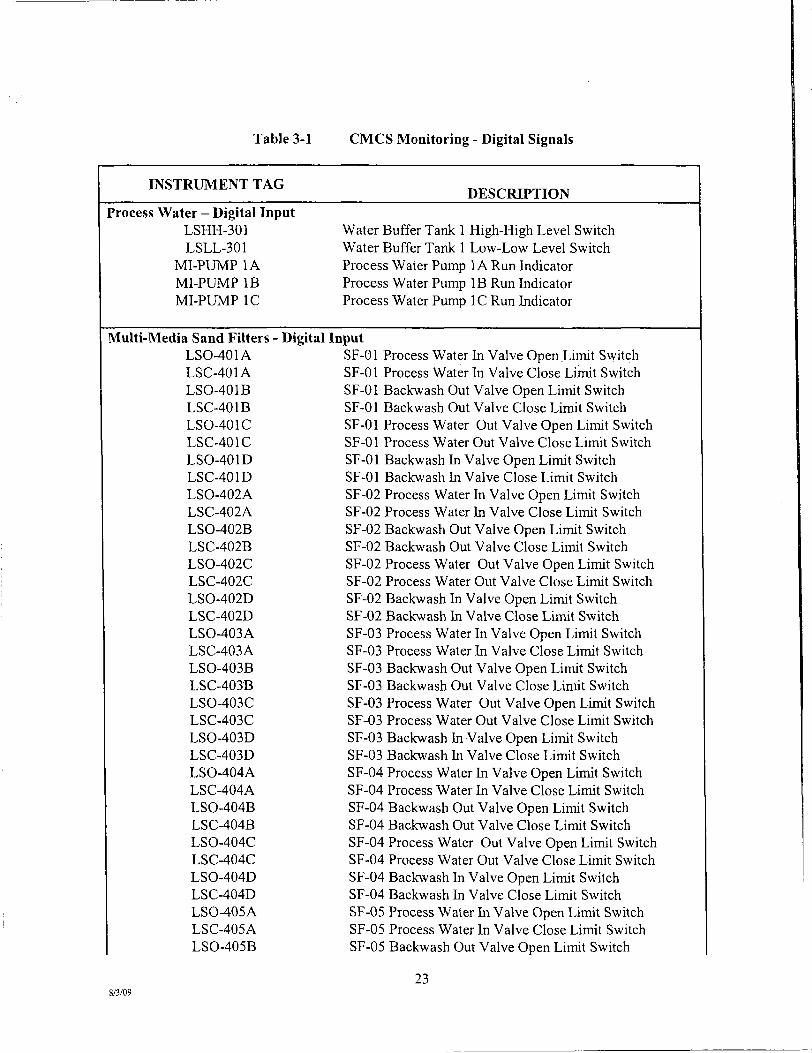
Table 3-1 CMCS Monitoring - Digital Signals
INSTRUMENT TAG DESCRIPTION
Process Water - Digital Input LSHH-301 LSLL-301
MI-PUMP lA MI-PUMP IB MI-PUMP IC
Water Buffer Tank 1 High-High Level Switch Water Buffer Tank 1 Low-Low Level Switch Process Water Pump 1A Run Indicator Process Water Pump IB Run Indicator Process Water Pump IC Run Indicator
Multi-Media Sand Filters LSO-401A LSC-401A LSO-401B LSC-401B LSO-401C LSC-401C LSO-401D LSC-401D LSO-402A LSC-402A LSO-402B LSC-402B LSO-402C LSC-402C LSO-402D LSC-402D LSO-403A LSC-403A LSO-403B LSC-403B LSO-403C LSC-403C LSO-403D LSC-403D LSO-404A LSC-404A LSO-404B LSC-404B LSO-404C LSC-404C LSO-404D LSC-404D LSO-405A LSC-405A LSO-405B
8/3/09
Digital Input SF-01 Process Water In Valve Open Limit Switch SF-01 Process Water In Valve Close Limit Switch SF-01 Backwash Out Valve Open Limit Switch SF-01 Backwash Out Valve Close Limit Switch SF-01 Process Water Out Valve Open Limit Switch SF-01 Process Water Out Valve Close Limit Switch SF-01 Backwash In Valve Open Limit Switch SF-01 Backwash In Valve Close Limit Switch SF-02 Process Water In Valve Open Limit Switch SF-02 Process Water In Valve Close Limit Switch SF-02 Backwash Out Valve Open Limit Switch SF-02 Backwash Out Valve Close Limit Switch SF-02 Process Water Out Valve Open Limit Switch SF-02 Process Water Out Valve Close Limit Switch SF-02 Backwash In Valve Open Limit Switch SF-02 Backwash In Valve Close Limit Switch SF-03 Process Water In Valve Open Limit Switch SF-03 Process Water In Valve Close Limit Switch SF-03 Backwash Out Valve Open Limit Switch SF-03 Backwash Out Valve Close Limit Switch SF-03 Process Water Out Valve Open Limit Switch SF-03 Process Water Out Valve Close Limit Switch SF-03 Backwash In Valve Open Limit Switch SF-03 Backwash In Valve Close Limit Switch SF-04 Process Water In Valve Open Limit Switch SF-04 Process Water In Valve Close Limit Switch SF-04 Backwash Out Valve Open Limit Switch SF-04 Backwash Out Valve Close Limit Switch SF-04 Process Water Out Valve Open Limit Switch SF-04 Process Water Out Valve Close Limit Switch SF-04 Backwash In Valve Open Limit Switch SF-04 Backwash In Valve Close Limit Switch SF-05 Process Water In Valve Open Limit Switch SF-05 Process Water In Valve Close Limit Switch SF-05 Backwash Out Valve Open Limit Switch
23

LSC-405B LSO-405C LSC-405C LSO-405D LSC-405D LSO-406A LSC-406A LSO-406B LSC-406B LSO-406C LSC-406C LSO-406D LSC-406D LSO-407A LSC-407A LSO-407B LSC-407B LSO-407C LSC-407C LSO-407D LSC-407D LSO-408A LSC-408A LSO-408B LSC-408B LSO-408C LSC-408C LSO-408D LSC-408D LSO-409A LSC-409A LSO-409B LSC-409B LSO-409C LSC-409C LSO-409D LSC-409D LSO-410A LSC-410A LSO-410B LSC-410B LSO-410C LSC-410C LSO-410D LSC-410D LS0-411A LSC-411A LS0-411B LSC-411B LS0-411C LSC-411C
SF-05 Backwash Out Valve Close Limit Switch SF-05 Process Water Out Valve Open Limit Switch SF-05 Process Water Out Valve Close Limit Switch SF-05 Backwash In Valve Open Limit Switch SF-05 Backwash In Valve Close Limit Switch SF-06 Process Water In Valve Open Limit Switch SF-06 Process Water In Valve Close Limit Switch SF-06 Backwash Out Valve Open Limit Switch SF-06 Backwash Out Valve Close Limit Switch SF-06 Process Water Out Valve Open Limit Switch SF-06 Process Water Out Valve Close Limit Switch SF-06 Backwash In Valve Open Limit Swhch SF-06 Backwash In Valve Close Limit Switch SF-07 Process Water hi Valve Open Limit Switch SF-07 Process Water In Valve Close Limit Switch SF-07 Backwash Out Valve Open Limit Switch SF-07 Backwash Out Valve Close Limit Switch SF-07 Process Water Out Valve Open Limit Switch SF-07 Process Water Out Valve Close Limit Switch SF-07 Backwash In Valve Open Limit Switch SF-07 Backwash In Valve Close Limit Switch SF-08 Process Water In Valve Open Limit Switch SF-08 Process Water In Valve Close Limit Switch SF-08 Backwash Out Valve Open Limit Switch SF-08 Backwash Out Valve Close Limit Switch SF-08 Process Water Out Valve Open Limit Switch SF-08 Process Water Out Valve Close Limit Switch SF-08 Backwash In Valve Open Limit Switch SF-08 Backwash In Valve Close Limit Switch SF-09 Process Water In Valve Open Limit Switch SF-09 Process Water In Valve Close Limit Switch SF-09 Backwash Out Valve Open Limit Switch SF-09 Backwash Out Valve Close Limit Switch SF-09 Process Water Out Valve Open Limit Switch SF-09 Process Water Out Valve Close Limit Switch SF-09 Backwash In Valve Open Limit Swhch SF-09 Backwash In Valve Close Limit Switch SF-10 Process Water In Valve Open Limit Switch SF-10 Process Water In Valve Close Limit Switch SF-10 Backwash Out Valve Open Limit Switch SF-10 Backwash Out Valve Close Limit Switch SF-10 Process Water Out Valve Open Limit Switch SF-10 Process Water Out Valve Close Limit Switch SF-10 Backwash In Valve Open Limit Switch SF-10 Backwash In Valve Close Limit Switch SF-11 Process Water In Valve Open Limit Switch SF-11 Process Water In Valve Close Limit Switch SF-11 Backwash Out Valve Open Limit Switch SF-11 Backwash Out Valve Close Limit Switch SF-11 Process Water Out Valve Open Limit Switch SF-11 Process Water Out Valve Close Limit Switch
24
8/3/09

LS0-411D LSC-411D LSO-412A LSC-412A LSO-412B LSC-412B LSO-412C LSC-412C LSO-412D LSC-412D LSO-413A LSC-413A LSO-413B LSC-413B LSO-413C LSC-413C LSO-413D LSC-413D LSO-414A LSC-414A LSO-414B LSC-414B LSO-414C LSC-414C LSO-414D LSC-414D LSO-415A LSC-415A LSO-415B LSC-415B LSO-415C LSC-415C LSO-415D LSC-415D LSO-416A LSC-416A LSO-416B LSC-416B LSO-416C LSC-416C LSO-416D LSC-416D LSO-417A LSC-417A LSO-417B LSC-417B LSO-417C LSC-417C LSO-417D LSC-417D LSO-418A
SF-11 Backwash hi Valve Open Limit Switch SF-11 Backwash In Valve Close Limit Switch SF-12 Process Water In Valve Open Limit Switch SF-12 Process Water In Valve Close Limit Switch SF-12 Backwash Out Valve Open Limit Switch SF-12 Backwash Out Valve Close Limit Switch SF-12 Process Water Out Valve Open Limit Switch SF-12 Process Water Out Valve Close Limit Switch SF-12 Backwash In Valve Open Limit Switch SF-12 Backwash In Valve Close Limit Switch SF-13 Process Water In Valve Open Limit Switch SF-13 Process Water In Valve Close Limit Switch SF-13 Backwash Out Valve Open Limit Switch SF-13 Backwash Out Valve Close Limit Switch SF-13 Process Water Out Valve Open Limit Switch SF-13 Process Water Out Valve Close Limit Switch SF-13 Backwash In Valve Open Limit Switch SF-13 Backwash In Valve Close Limit Switch SF-14 Process Water In Valve Open Limit Switch SF-14 Process Water In Valve Close Limit Switch SF-14 Backwash Out Valve Open Limit Switch SF-14 Backwash Out Valve Close Limit Switch SF-14 Process Water Out Valve Open Limit Switch SF-14 Process Water Out Valve Close Limit Switch SF-14 Backwash In Valve Open Limit Switch SF-14 Backwash In Valve Close Limit Switch SF-15 Process Water In Valve Open Limit Switch SF-15 Process Water In Valve Close Limit Switch SF-15 Backwash Out Valve Open Limit Switch SF-15 Backwash Out Valve Close Limit Switch SF-15 Process Water Out Valve Open Limit Switch SF-15 Process Water Out Valve Close Limit Switch SF-15 Backwash In Valve Open Limit Switch SF-15 Backwash In Valve Close Limit Switch SF-16 Process Water In Valve Open Limit Switch SF-16 Process Water In Valve Close Limit Switch SF-16 Backwash Out Valve Open Limit Switch SF-16 Backwash Out Valve Close Limit Switch SF-16 Process Water Out Valve Open Limit Switch SF-16 Process Water Out Valve Close Limit Switch SF-16 Backwash In Valve Open Limit Switch SF-16 Backwash In Valve Close Limit Switch SF-17 Process Water In Valve Open Limit Switch SF-17 Process Water In Valve Close Limit Switch SF-17 Backwash Out Valve Open Limit Switch SF-17 Backwash Out Valve Close Limit Switch SF-17 Process Water Out Valve Open Limit Switch SF-17 Process Water Out Valve Close Limit Switch SF-17 Backwash In Valve Open Limit Switch SF-17 Backwash In Valve Close Limit Switch SF-18 Process Water In Valve Open Limit Switch
25
8/3/09

LSC-418A LSO-418B LSC-418B LSO-418C LSC-418C LSO-418D LSC-418D LSO-419A LSC-419A LSO-419B LSC-419B LSO-419C LSC-419C LSO-419D LSC-419D LSO-420A LSC-420A LSO-420B LSC-420B LSO-420C LSC-420C LSO-420D LSC-420D LSO-421A LSC-421A LSO-421B LSC-421B LSO-421C LSC-421C LSO-421D LSC-421D LSO-422A LSC-422A LSO-422B LSC-422B LSO-422C LSC-422C LSO-422D LSC-422D LSO-423A LSC-423A LSO-423B LSC-423B LSO-423C LSC-423C LSO-423D LSC-423D LSO-424A LSC-424A LSO-424B LSC-424B
SF-18 Process Water hi Valve Close Limit Switch SF-18 Backwash Out Valve Open Limit Switch SF-18 Backwash Out Valve Close Limit Switch SF-18 Process Water Out Valve Open Limit Switch SF-18 Process Water Out Valve Close Limit Switch SF-18 Backwash In Valve Open Limit Switch SF-18 Backwash In Valve Close Limit Switch SF-19 Process Water In Valve Open Limit Switch SF-19 Process Water In Valve Close Limit Switch SF-19 Backwash Out Valve Open Limit Switch SF-19 Backwash Out Valve Close Limit Switch SF-19 Process Water Out Valve Open Limit Switch SF-19 Process Water Out Valve Close Limit Switch SF-19 Backwash In Valve Open Limit Switch SF-19 Backwash In Valve Close Limit Switch SF-20 Process Water In Valve Open Limit Switch SF-20 Process Water In Valve Close Limit Switch SF-20 Backwash Out Valve Open Limit Switch SF-20 Backwash Out Valve Close Limit Switch SF-20 Process Water Out Valve Open Limit Switch SF-20 Process Water Out Valve Close Limit Switch SF-20 Backwash In Valve Open Limit Switch SF-20 Backwash In Valve Close Limit Switch SF-21 Process Water In Valve Open Limit Switch SF-21 Process Water In Valve Close Limit Switch SF-21 Backwash Out Valve Open Limit Switch SF-21 Backwash Out Valve Close Limit Switch SF-21 Process Water Out Valve Open Limit Switch SF-21 Process Water Out Valve Close Limit Switch SF-21 Backwash In Valve Open Limit Switch SF-21 Backwash In Valve Close Limit Switch SF-22 Process Water In Valve Open Limit Switch SF-22 Process Water In Valve Close Limit Switch SF-22 Backwash Out Valve Open Limit Switch SF-22 Backwash Out Valve Close Limit Switch SF-22 Process Water Out Valve Open Limit Switch SF-22 Process Water Out Valve Close Limit Switch SF-22 Backwash In Valve Open Limit Switch SF-22 Backwash In Valve Close Limit Switch SF-23 Process Water In Valve Open Lunit Switch SF-23 Process Water In Valve Close Limit Switch SF-23 Backwash Out Valve Open Limit Switch SF-23 Backwash Out Valve Close Limit Switch SF-23 Process Water Out Valve Open Limit Switch SF-23 Process Water Out Valve Close Limit Switch SF-23 Backwash In Valve Open Limit Switch SF-23 Backwash In Valve Close Limit Switch SF-24 Process Water In Valve Open Limit Switch SF-24 Process Water In Valve Close Limit Switch SF-24 Backwash Out Valve Open Limit Switch SF-24 Backwash Out Valve Close Limit Switch
26
8/3/09

LSO-424C LSC-424C LSO-424D LSC-424D
SF-24 Process Water Out Valve Open Limit Switch SF-24 Process Water Out Valve Close Limit Switch SF-24 Backwash In Valve Open Limit Switch SF-24 Backwash In Valve Close Limit Switch
Effluent Water - Digital Input LSHH-701 LSLL-701
MI-PUMP 2A MI-PUMP 2B MI-PUMP 2C
LSO-BFV 2A
LSC-BFV 2A
LSO-BFV 2B
LSC-BFV 2B
LSO-BFV 2C
LSC-BFV 2C
Effluent Tank High-High Level Switch Effluent Tank Low-Low Level Switch Effluent Water Discharge Pump 2A Run Indicator Effluent Water Discharge Pump 2B Run Indicator Effluent Water Discharge Pump 2C Run Indicator Effluent Pump 2A Discharge MOV BFV-2A Open Limit Switch Effluent Pump 2A Discharge MOV BFV-2A Close Limit Switch Effluent Pump 2B Discharge MOV BFV-2B Open Limit Switch EffluentPump 2B Discharge MOV BFV-2B Close Limit Switch Effluent Pump 2C Discharge MOV BFV-2C Open Limit Switch Effluent Pump 2C Discharge MOV BFV-2C Close Limit Switch
Building Sump - Digital Input LSL-770 LSH-770
LSHH-770 MI-PUMP 3A MI-PUMP 3B
Building Sump Low Level Switch Building Sump High Level Switch Building Sump High-High Level Switch Building Sump Pump 3A Run Indicator Building Sump Pump 3B Run Indicator
Backwash Water - Digital Input MI-PUMP 5A MI-PUMP 5B
Backwash Pump 5A Run Indicator Backwash Pump 5B Run Indicator
Compressed Air - Digital Input PSH Air Compressor AC-01 Pressure Switch
Plant Safety - Digital Input FA
ELEC POWER Fire Alarm Loss of Electric Power
Process Water - Digital Output MC-PUMP lA
SHDN-PUMP lA MC-PUMP IB
SHDN-PUMP IB MC-PUMP IC
SHDN-PUMP IC
8/3/09
Process Water Pump 1A Start-Stop Process Water Pump 1A Shut Down Process Water Pump IB Start-Stop Process Water Pump IB Shut Down Process Water Pump IC Start-Stop Process Water Pump 1C Shut Down
27

Multi-Media Sand Filters Output
SOV-401A SOV-401B SOV-401C SOV-401D SOV-402A SOV-402B SOV-402C SOV-402D SOV-403A SOV-403B SOV-403C SOV-403D SOV-404A SOV-404B SOV-404C SOV-404D SOV-405A SOV-405B SOV-405C SOV-405D SOV-406A SOV-406B SOV-406C SOV-406D SOV-407A SOV-407B SOV-407C SOV-407D SOV-408A SOV-408B SOV-40.8C SOV-408D SOV-409A SOV-409B SOV-409C SOV-409D SOV-410A SOV-410B SOV-410C SOV-410D S0V-411A S0V-411B S0V-411C S0V-411D SOV-412A SOV-412B SOV-412C SOV-412D SOV-413A
8/3/09
Digital
SF-01 Process Water In Valve Solenoid Control SF-01 Backwash Out Valve Solenoid Control SF-01 Process Water Out Valve Solenoid Control SF-01 Backwash In Valve Solenoid Control SF-02 Process Water In Valve Solenoid Control SF-02 Backwash Out Valve Solenoid Control SF-02 Process Water Out Valve Solenoid Control SF-02 Backwash In Valve Solenoid Control SF-03 Process Water In Valve Solenoid Control SF-03 Backwash Out Valve Solenoid Control SF-03 Process Water Out Valve Solenoid Control SF-03 Backwash In Valve Solenoid Control SF-04 Process Water In Valve Solenoid Control SF-04 Backwash Out Valve Solenoid Control SF-04 Process Water Out Valve Solenoid Control SF-04 Backwash In Valve Solenoid Control SF-05 Process Water hi Valve Solenoid Control SF-05 Backwash Out Valve Solenoid Control SF-05 Process Water Out Valve Solenoid Control SF-05 Backwash In Valve Solenoid Control SF-06 Process Water In Valve Solenoid Control SF-06 Backwash Out Valve Solenoid Control SF-06 Process Water Out Valve Solenoid Control SF-06 Backwash In Valve Solenoid Control SF-07 Process Water In Valve Solenoid Control SF-07 Backwash Out Valve Solenoid Control SF-07 Process Water Out Valve Solenoid Control SF-07 Backwash In Valve Solenoid Control SF-08 Process Water In Valve Solenoid Control SF-08 Backwash Out Valve Solenoid Control SF-08 Process Water Out Valve Solenoid Control SF-08 Backwash hi Valve Solenoid Control SF-09 Process Water In Valve Solenoid Control SF-09 Backwash Out Valve Solenoid Control SF-09 Process Water Out Valve Solenoid Control SF-09 Backwash hi Valve Solenoid Control SF-10 Process Water In Valve Solenoid Control SF-10 Backwash Out Valve Solenoid Control SF-10 Process Water Out Valve Solenoid Control SF-10 Backwash In Valve Solenoid Control SF-11 Process Water In Valve Solenoid Control SF-11 Backwash Out Valve Solenoid Control SF-11 Process Water Out Valve Solenoid Control SF-11 Backwash In Valve Solenoid Control SF-12 Process Water In Valve Solenoid Control SF-12 Backwash Out Valve Solenoid Control SF-12 Process Water Out Valve Solenoid Control SF-12 Backwash In Valve Solenoid Control SF-13 Process Water In Valve Solenoid Control
28

SOV-413B SOV-413C SOV-413D SOV-414A SOV-414B SOV-414C SOV-414D SOV-415A SOV-415B SOV-415C SOV-415D SOV-416A SOV-416B SOV-416C SOV-416D SOV-417A SOV-417B SOV-417C SOV-417D SOV-418A SOV-418B SOV-418C SOV-418D SOV-419A SOV-419B SOV-419C SOV-419D SOV-420A SOV-420B SOV-420C SOV-420D SOV-421A SOV-421B SOV-421C SOV-421D SOV-422A SOV-422B SOV-422C SOV-422D SOV-423A SOV-423B SOV-423C SOV-423D SOV-424A SOV-424B SOV-424C SOV-424D
SF-13 Backwash Out Valve Solenoid Control SF-13 Process Water Out Valve Solenoid Control SF-13 Backwash In Valve Solenoid Control SF-14 Process Water In Valve Solenoid Control SF-14 Backwash Out Valve Solenoid Control SF-14 Process Water Out Valve Solenoid Control SF-14 Backwash In Valve Solenoid Control SF-15 Process Water In Valve Solenoid Control SF-15 Backwash Out Valve Solenoid Control SF-15 Process Water Out Valve Solenoid Control SF-15 Backwash In Valve Solenoid Control SF-16 Process Water In Valve Solenoid Control SF-16 Backwash Out Valve Solenoid Control SF-16 Process Water Out Valve Solenoid Control SF-16 Backwash In Valve Solenoid Control SF-17 Process Water In Valve Solenoid Control SF-17 Backwash Out Valve Solenoid Control SF-17 Process Water Out Valve Solenoid Control SF-17 Backwash In Valve Solenoid Control SF-18 Process Water In Valve Solenoid Control SF-18 Backwash Out Valve Solenoid Control SF-18 Process Water Out Valve Solenoid Control SF-18 Backwash In Valve Solenoid Control SF-19 Process Water In Valve Solenoid Control SF-19 Backwash Out Valve Solenoid Control SF-19 Process Water Out Valve Solenoid Control SF-19 Backwash In Valve Solenoid Control SF-20 Process Water In Valve Solenoid Control SF-20 Backwash Out Valve Solenoid Control SF-20 Process Water Out Valve Solenoid Control SF-20 Backwash In Valve Solenoid Control SF-21 Process Water In Valve Solenoid Control SF-21 Backwash Out Valve Solenoid Control SF-21 Process Water Out Valve Solenoid Control SF-21 Backwash hi Valve Solenoid Control SF-22 Process Water In Valve Solenoid Control SF-22 Backwash Out Valve Solenoid Control SF-22 Process Water Out Valve Solenoid Control SF-22 Backwash In Valve Solenoid Control SF-23 Process Water In Valve Solenoid Control SF-23 Backwash Out Valve Solenoid Control SF-23 Process Water Out Valve Solenoid Control SF-23 Backwash In Valve Solenoid Control SF-24 Process Water In Valve Solenoid Control SF-24 Backwash Out Valve Solenoid Control SF-24 Process Water Out Valve Solenoid Control SF-24 Backwash In Valve Solenoid Control
Effluent Water - Digital Output MC-PUMP 2A
SHDN-PUMP 2A
8/3/09
Effluent Water Discharge Pump 2A Start-Stop Effluent Water Discharge Pump 2A Shut Down
29

MC-PUMP 2B SHDN-PUMP 2B
MC-PUMP 2C SHDN-PUMP 2C MCO- BFV 2A MCC-BFV 2A MCO- BFV 2B MCC-BFV 2B MCO- BFV 2C MCC-BFV 2C
Effluent Effluent Effluent Effluent Effluent Effluent Effluent Effluent Effluent Effluent
Water Discharge Pump 2B Water Discharge Pump 2B Water Discharge Pump 2C Water Discharge Pump 2C Pump 2A Discharge MOV Pump 2A Discharge MOV Pump 2B Discharge MOV Pump 2B Discharge MOV Pump 2C Discharge MOV Pump 2C Discharge MOV
Start-Stop Shut Down Start-Stop Shut Down BFV-2A Open Signal BFV-2A Close Signal BFV-2B Open Signal BFV-2B Close Signal BFV-2C Open Signal BFV-2C Close Signal
Building Sump - Digital Output MC-PUMP 3A
SHDN-PUMP 3A MC-PUMP 3B
SHDN-PUMP 3B
Building Sump Pump 3A Start-Stop Building Sump Pump 3A Shut Down Building Sump Pump 3B Start-Stop Building Sump Pump 3B Shut Down
Backwash Water - Digital Output MC-PUMP 5A
SHDN-PUMP 5A MC-PUMP 5B
SHDN-PUMP 5B
Backwash Pump 5A Start-Stop Backwash Pump 5A Shut Down Backwash Pump 5B Start-Stop Backwash Pump 5B Shut Down
Compressed Air - Digital Output SHDN-ACOl Air Compressor AC-01 Shut Down Signal
Table 3-2 CMCS Monitoring - Analog Signals
INSTRUMENT TAG DESCRIPTION
Process Water -AElT-301 LIT-301
SI-PUMP lA SI-PUMP IB SI-PUMP IC
FQIT-304
Analog Input Water Buffer Tank 1 pH Indicator Transmitter Water Buffer Tank 1 Level Indicator Transmitter Process Water Pump 1A Speed Indicator Process Water Pump IB Speed Indicator Process Water Pump 1C Speed Indicator Process Water Flow To Sand Filter Totalizer
Multi-Media Sand Filter - Analog Input FlT-401 FIT-402 FlT-403 FIT-404 FIT-405 FIT-406 FIT-407 FlT-408
SF-01 Flow SF-02 Flow SF-03 Flow SF-04 Flow SF-05 Flow SF-06 Flow SF-07 Flow SF-08 Flow
Indicator Indicator Indicator Indicator Indicator Indicator Indicator Indicator
Transmitter Transmitter Transmitter Transmitter Transmitter Transmitter Transmitter Transmitter
30 8/3/09
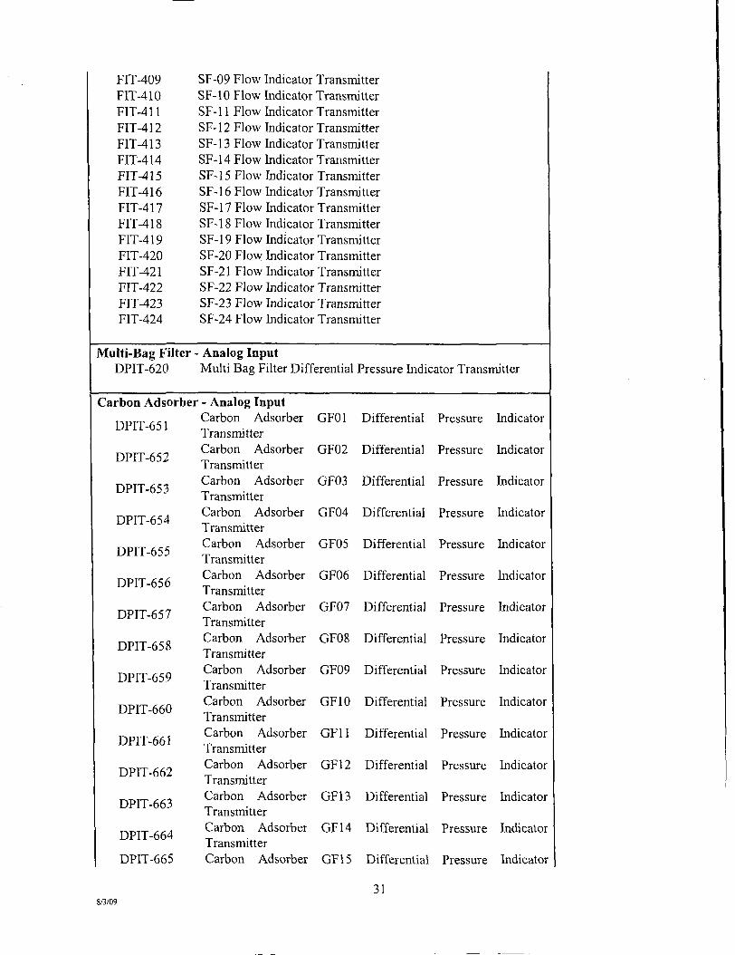
FlT-409 FIT-410 FlT-411 FlT-412 FlT-413 FIT-414 FIT-415 FIT-416 FIT-417 FIT-418 FlT-419 FlT-420 FIT-421 FIT-422 FlT-423 FIT-424
SF-09 Flow SF-10 Flow SF-11 Flow SF-12 Flow SF-13 Flow SF-14 Flow SF-15 Flow SF-16 Flow SF-17 Flow SF-18 Flow SF-19 Flow SF-20 Flow SF-21 Flow SF-22 Flow SF-23 Flow SF-24 Flow
Indicator Transmitter Indicator Transmitter Indicator Transmitter Indicator Transmitter Indicator Transmitter Indicator Transmitter Indicator Transmitter Indicator Transmitter Indicator Transmitter Indicator Transmitter Indicator Transmitter Indicator Transmitter Indicator Transmitter Indicator Transmitter Indicator Transmitter Indicator Transmitter
Multi-Bag Filter - Analog Input DPIT-620 Multi Bag Fiher Differential Pressure Indicator Transmitter
Carbon Adsorber
DPIT-651
DPlT-652
DPlT-653
DPlT-654
DPIT-655
DPlT-656
DPIT-657
DPIT-658
DPlT-659
DPlT-660
DPlT-661
DPlT-662
DPlT-663
DPIT-664
DPIT-665
8/3/09
- Analog Input Carbon Adsorber Transmitter Carbon Adsorber Transmitter Carbon Adsorber Transmitter Carbon Adsorber Transmitter Carbon Adsorber Transmitter Carbon Adsorber Transmitter Carbon Adsorber Transmitter Carbon Adsorber Transmitter Carbon Adsorber Transmitter Carbon Adsorber Transmitter Carbon Adsorber Transmitter Carbon Adsorber Transmitter Carbon Adsorber Transmitter Carbon Adsorber Transmitter Carbon Adsorber
GFOl
GF02
GF03
GF04
GF05
GF06
GF07
GF08
GF09
GFIO
GFll
GF12
GF13
GF14
GF15
Differential Pressure Indicator
Differential Pressure Indicator
Differential Pressure Indicator
Differential Pressure Indicator
Differential Pressure Indicator
Differential Pressure Indicator
Differential Pressure Indicator
Differential Pressure Indicator
Differential Pressure Indicator
Differential Pressure Indicator
Differential Pressure Indicator
Differential Pressure Indicator
Differential Pressure Indicator
Differential Pressure Indicator
Differential Pressure Indicator
31
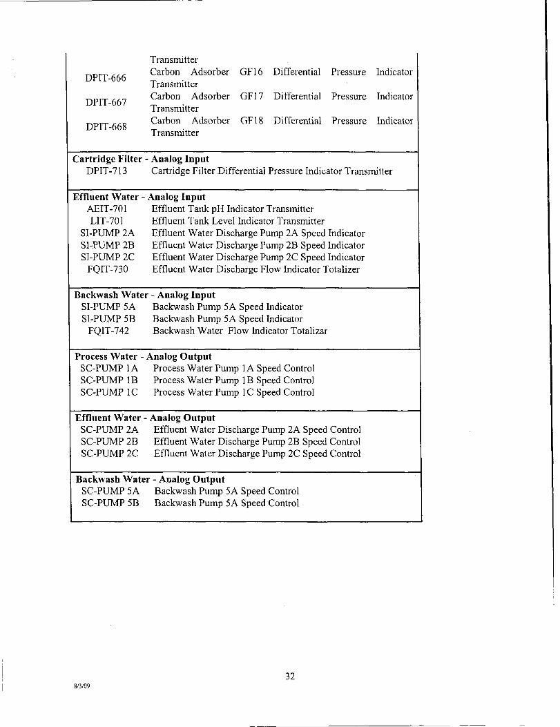
DPlT-666
DPlT-667
DPlT-668
Transmitter Carbon Adsorber GF16 Differential Pressure Indicator Transmitter Carbon Adsorber GF17 Differential Pressure Indicator Transmitter Carbon Adsorber GF18 Differential Pressure Indicator Transmitter
Cartridge Filter DPIT-713
Analog Input Cartridge Filter Differential Pressure Indicator Transmitter
Effluent Water - Analog Input AEIT-701 Effluent Tank pH Indicator Transmitter LIT-701 Effluent Tank Level Indicator Transmitter
SI-PUMP 2A Effluent Water Discharge Pump 2A Speed hidicator SI-PUMP 2B Effluent Water Discharge Pump 2B Speed hidicator SI-PUMP 2C Effluent Water Discharge Pump 2C Speed Indicator
FQIT-730 Effluent Water Discharge Flow Indicator Totalizer
Backwash Water - Analog Input SI-PUMP 5A Backwash Pump 5A Speed hidicator SI-PUMP 5B Backwash Pump 5A Speed hidicator
FQlT-742 Backwash Water Flow Indicator Totalizar
Process Water - Analog Output SC-PUMP 1A Process Water Pump 1A Speed Control SC-PUMP IB Process Water Pump IB Speed Control SC-PUMP IC Process Water Pump IC Speed Control
Effluent Water - Analog Output SC-PUMP 2A Effluent Water Discharge Pump 2A Speed Control SC-PUMP 2B Effluent Water Discharge Pump 2B Speed Control SC-PUMP 2C Effluent Water Discharge Pump 2C Speed Control
Backwash Water - Analog Output SC-PUMP 5A Backwash Pump 5A Speed Control SC-PUMP 5B Backwash Pump 5A Speed Control
32 8/3/09
3.2.2 Equipment Operation Monitoring
Reports will be generated to document regular equipment inspections and operational parameters. The following information will be documented on the "Daily Inspection Form" located in Appendix A, Report Forms:
• Visual inspection of all piping, fixtures, pumps and tanks to check for leaks or visible signs of wear;
• Visual inspection of water flow throughout system via designated sight tubes within the system; and
• Visual inspection of security, heating and ventilation and fire protection systems.
Specific preventative maintenance on the equipment is described in Section 9.0, Equipment Maintenance of the Manual. Maintenance perfomied for each piece of equipment is to be recorded using the ''Equipment Maintenance Form", located in Appendix A, Report Forms.
3.3 Laboratory Data
Laboratory results from the WTP process and waste sampling will be summarized in the quarterly status and monitoring reports to be prepared by Tetra Tech.
3.4 Inventory Monitoring and Recording
It is recommended that the Operator monitor and record all equipment used during regular treatment system operations at least on a weekly basis and make an inventory. This includes process equipment, as well as, building maintenance supplies/equipment. This information is to be included in the Equipment Maintenance Form, found in Appendix A, Report Forms. Reference is also made to the "Tools and Equipment List" found in Appendix B, Tools and Equipment, and the "Spare Parts Inventory" located in Appendix C, Spare Parts.
3.5 Personnel Management
On-site personnel management is an important part of the efficient operation and maintenance of the WTP. Location of on-site personnel is essential in order to meet site health and safety protocol.
Personnel management includes records of time on-site for the Operator, as well as, visitors and security personnel. Operators are to prepare daily logs for inclusion in weekly employer timesheets.
33 8/3/09

4.0 SAMPLING AND ANALYSIS PLAN DESCRIPTION
4.1 Purpose
The purpose of this sampling and analysis plan (SAP) section is to describe data acquisition procedures, numbers and types of samples, methods of analysis, and quality control measures associated with data collection and analysis for the WTP. The detailed definition of quality assurance (QA) and quality control (QC) for all sampling related project activities to be implemented at the Lower Fox River Site is covered in a separate document, the Quality Assurance Project Plan (QAPP), which ensures the integrity of the work to be performed at the Site and ensures that the data collected will be of the appropriate type and quality needed for their intended use. This SAP is intended to be a procedural guide for all Tetra Tech team personnel and subcontractors involved in sampling and analysis and data acquisition while implementing remedial actions for the Lower Fox River Site OUs 2 to 5. Sampling of process aqueous samples is described in SOP002 in Attachment 2 of the QAPP and is also included in Appendix A ofthis O&M Plan.
4.2 Sampling and Analysis Data Objectives
This section gives an overview of sampling and analysis activities and their data objectives. Sampling and analysis activities for the WTP consist of: 1) process monitoring and sampling; and, 2) monitoring and characterization of the effluent streams (backwash water from multi-media sand filtration and granular activated carbon adsorption pumped to the SDDP Overflow Tank, treated water pumped to the SDDP and returned to the Lower Fox River via the submerged multi-port diffuser, and spent filter media [multi-media sand, bags, and cartridges] for waste disposal) from the WTP.
4.2.1 Generalized Scope of Work
Process monitoring and sampling and effluent stream characterization activities for this project will include the following:
• Sampling and monitoring of influent, effluent, and intermediate process streams within the WTP for the purpose of evaluating the operation and performance of the process equipment used for multi-media sand filtration, bag filtration, cartridge filtration, granular activated carbon adsorption, and backwashing during routine operations.
• Sampling and monitoring of the WTP performance during the start-up period in 2009 in order to ensure that the system is operating properly and that effluent streams meet all regulatory and disposal facility requirements.
• Sampling and monitoring of the WTP during the prove-out period in 2009 in order to ensure that the system is operating in accordance with the design specifications and meets all regulatory and disposal facility requirements.
Other activities include sampling and analysis for health and safety related monitoring of the indoor air within the WTP building as well as sampling and analysis for waste characterization purposes. Sampling and analysis for monitoring of the indoor air is discussed in detail in the Site Health and Safety Plan (SHSP).
34 8/3/09

4.2.2 Data Quality Objectives
Data Quality Objectives (DQOs) are requirements needed to support decisions relative to the various site activities. Sampling procedures and analytical data collected must be of a quality that supports the decision making process and ensures that project objectives are achieved. The sampling and analysis program will ensure that data meet the requirements for precision, accuracy, representativeness, comparability, completeness, and sensitivity defined in the QAPP. Project Quality Objectives and Systematic Planning Process Statements are stated in QAPP Worksheet #11. Measurement Performance Criteria for the various matrices and analyses are stated in QAPP Worksheet #12. The Reference Limits and Evaluation Table for the various matrices and analyses are provided in QAPP Worksheet #15.
Samples will be analyzed in strict accordance with the analytical test methods and procedures in NR 219, utilizing approved USEPA and ASTM methods. Analytical methods will provide results with detection limits sufficiently below designated action levels, and the methods will be accurate enough to quantify contamination at concentrations below action levels. Sample collection will utilize approved techniques that will ensure that the sample is representative of current environmental and operational conditions. QA/QC samples will be collected and analyzed for the purpose of assessing the quality of the sampling effort and of the analytical data. A description and frequency of QA/QC samples to be collected is specified in Section 4.3.2.
Laboratories providing chemical measurements for the purposes of determining the effectiveness of the remediation must be certified by the State of Wisconsin under NR 149 for aqueous media and the appropriate analytes and methods, and all laboratory methods must meet the reporting limit requirements acceptable to both the USEPA and WDNR. Tetra Tech plans to send samples for a particular analytical parameter only to those laboratories that have been certified by the State of Wisconsin for that parameter. To the extent possible, Tetra Tech plans to utilize local certified laboratories with the samples being delivered to the certified laboratory by a local courier service instead of shipping samples via an overnight delivery service to laboratories that are further away. Only if required during the project (e.g., the chosen laboratory loses its certification for the parameter, etc.) will additional laboratories be utilized for analysis of a particular parameter. Section 2.5.1 of the QAPP provides information on substitution of laboratories. The primary subcontract laboratory performing chemical analytical services related to the WTP is as follows:
• Pace Analytical, Green Bay, Wisconsin (Chemical Analytical Laboratory).
A Project Manager and QA Manager will be assigned by each laboratory to the project, and they will provide technical guidance to the project team, oversee laboratory requirements (including QA/QC requirements) for the project, review laboratory data for compliance with approved plarming documents, maintain laboratory documentation, and coordinate corrective action procedures as necessary. The Tetra Tech QA/QC Manager, in concert with the Tetra Tech Database Management Specialist, will coordinate with the laboratories on the number and type of analytical samples necessary. The subcontractor laboratory(ies) will be responsible for the delivery of sample bottles (pre-preserved as necessary) to the Site, and subsequent pick-up/shipment and analysis of collected samples. Data packages will be submitted by the subcontractor laboratories directly to the Tetra Tech Team.
4.3 Sampling Program Procedures and Requirements
This section discusses and summarizes the sampling and monitoring activities described in the Scope of Work and summarized in Section 4.2.1, and identifies chemical and physical sampling requirements for this program.
35 8/3/09
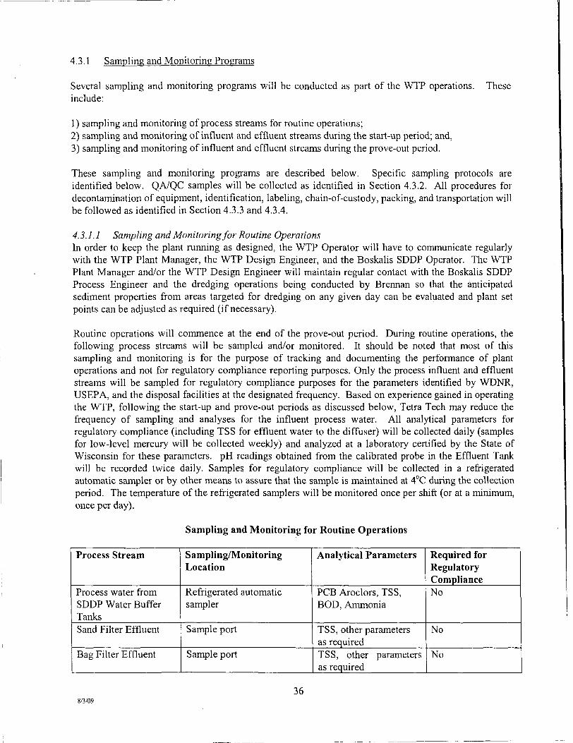
4.3.1 Sampling and Monitoring Programs
Several sampling and monitoring programs will be conducted as part of the WTP operations. These include:
1) sampling and monitoring of process streams for routine operations; 2) sampling and monitoring of influent and effluent streams during the start-up period; and, 3) sampling and monitoring of influent and effluent streams during the prove-out period.
These sampling and monitoring programs are described below. Specific sampling protocols are identified below. QA/QC samples will be collected as identified in Section 4.3.2. All procedures for decontamination of equipment, identification, labeling, chain-of-custody, packing, and transportation will be followed as identified in Section 4.3.3 and 4.3.4.
4.3.1.1 Sampling and Monitoring for Routine Operations hi order to keep the plant running as designed, the WTP Operator will have to communicate regularly with the WTP Plant Manager, the WTP Design Engineer, and the Boskalis SDDP Operator. The WTP Plant Manager and/or the WTP Design Engineer will maintain regular contact with the Boskalis SDDP Process Engineer and the dredging operations being conducted by Breiman so that the anticipated sediment properties from areas targeted for dredging on any given day can be evaluated and plant set points can be adjusted as required (if necessary).
Routine operations will commence at the end of the prove-out period. During routine operations, the following process streams will be sampled and/or monitored. It should be noted that most of this sampling and monitoring is for the purpose of tracking and documenting the performance of plant operations and not for regulatory compliance reporting purposes. Only the process influent and effluent streams will be sampled for regulatory compliance purposes for the parameters identified by WDNR, USEPA, and the disposal facilities at the designated frequency. Based on experience gained in operating the WTP, following the start-up and prove-out periods as discussed below, Tetra Tech may reduce the frequency of sampling and analyses for the influent process water. All analytical parameters for regulatory compliance (including TSS for effluent water to the diffuser) will be collected daily (samples for low-level mercury will be collected weekly) and analyzed at a laboratory certified by the State of Wisconsin for these parameters. pH readings obtained from the calibrated probe in the Effluent Tank will be recorded twice daily. Samples for regulatory compliance will be collected in a refrigerated automatic sampler or by other means to assure that the sample is maintained at 4°C during the collection period. The temperature of the refrigerated samplers will be monitored once per shift (or at a minimum, once per day).
Sampling and Monitoring for Routine Operations
Process Stream
Process water from SDDP Water Buffer Tanks Sand Filter Effluent
Bag Filter Effluent
Sampling/Monitoring Location
Refrigerated automatic sampler
Sample port
Sample port
Analytical Parameters
PCB Aroclors, TSS, BOD, Ammonia
TSS, other parameters as required TSS, other parameters as required
Required for Regulatory Compliance No
No
No
8/3/09 36
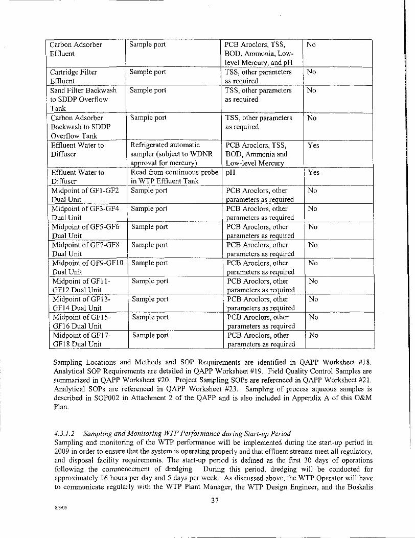
Carbon Adsorber Effluent
Cartridge Filter Effluent Sand Fiher Backwash to SDDP Overflow Tank Carbon Adsorber Backwash to SDDP Overflow Tank Effluent Water to Diffuser
Effluent Water to Diffuser Midpoint of GF1-GF2 Dual Unit Midpoint of GF3-GF4 Dual Unit Midpoint of GF5-GF6 Dual Unit Midpoint of GF7-GF8 Dual Unit MidpomtofGF9-GF10 Dual Unit Midpoint of GFll-GF12 Dual Unit Midpoint of GFl3-GF14 Dual Unit Midpoint of GFl 5-GF16 Dual Unit Midpoint of GFl 7-GF18 Dual Unit
Sample port
Sample port
Sample port
Sample port
Refrigerated automatic sampler (subject to WDNR approval for mercury) Read from continuous probe in WTP Effluent Tank Sample port
Sample port
Sample port
Sample port
Sample port
Sample port
Sample port
Sample port
Sample port
PCB Aroclors, TSS, BOD, Ammonia, Low-level Mercury, and pH TSS, other parameters as required TSS, other parameters as required
TSS, other parameters as required
PCB Aroclors, TSS, BOD, Ammonia and Low-level Mercury pH
PCB Aroclors, other parameters as required PCB Aroclors, other parameters as required PCB Aroclors, other parameters as required PCB Aroclors, other parameters as required PCB Aroclors, other parameters as required PCB Aroclors, other parameters as required PCB Aroclors, other parameters as required PCB Aroclors, other parameters as required PCB Aroclors, other parameters as required
No
No
No
No
Yes
Yes
No
No
No
No
No
No
No
No
No
Sampling Locations and Methods and SOP Requirements are identified in QAPP Worksheet #18. Analytical SOP Requirements are detailed in QAPP Worksheet #19. Field Quality Control Samples are summarized in QAPP Worksheet #20. Project Sampling SOPs are referenced in QAPP Worksheet #21. Analytical SOPs are referenced in QAPP Worksheet #23. Sampling of process aqueous samples is described in SOP002 in Attachment 2 of the QAPP and is also included in Appendix A of this O&M Plan.
4.3.1.2 Sampling and Monitoring IVTP Performance during Start-up Period Sampling and monitoring of the WTP performance will be implemented during the start-up period in 2009 in order to ensure that the system is operating properly and that effluent streams meet all regulatory, and disposal facility requirements. The start-up period is defined as the first 30 days of operations following the commencement of dredging. During this period, dredging will be conducted for approximately 16 hours per day and 5 days per week. As discussed above, the WTP Operator will have to communicate regularly with the WTP Plant Manager, the WTP Design Engineer, and the Boskalis
37 8/3/09
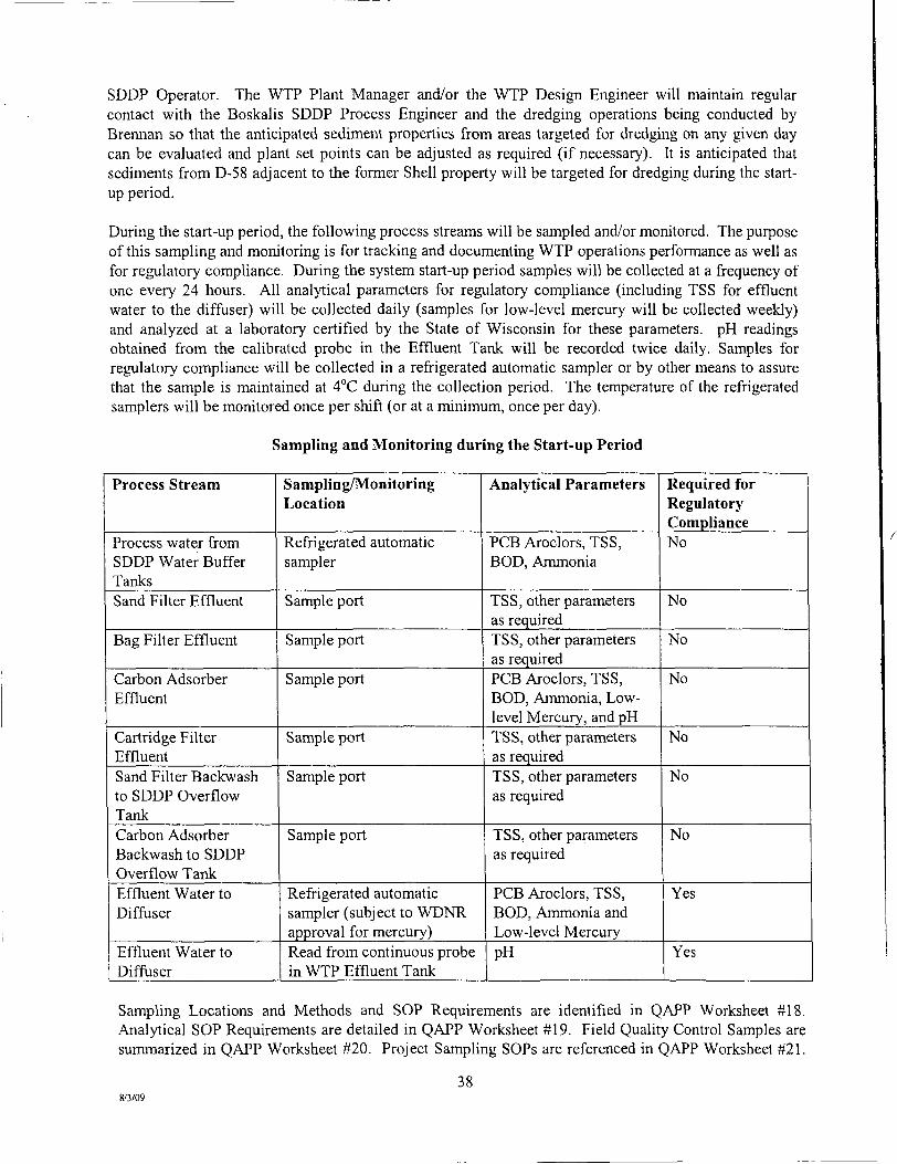
SDDP Operator. The WTP Plant Manager and/or the WTP Design Engineer will maintain regular contact with the Boskalis SDDP Process Engineer and the dredging operations being conducted by Brennan so that the anticipated sediment properties from areas targeted for dredging on any given day can be evaluated and plant set points can be adjusted as required (if necessary). It is anticipated that sediments from D-58 adjacent to the former Shell property will be targeted for dredging during the startup period.
During the start-up period, the following process streams will be sampled and/or monitored. The purpose ofthis sampling and monitoring is for tracking and documenting WTP operations performance as well as for regulatory compliance. During the system start-up period samples will be collected at a frequency of one every 24 hours. All analytical parameters for regulatory compliance (including TSS for effluent water to the diffiiser) will be collected daily (samples for low-level mercury will be collected weekly) and analyzed at a laboratory certified by the State of Wisconsin for these parameters. pH readings obtained from the calibrated probe in the Effluent Tank will be recorded twice daily. Samples for regulatory compliance will be collected in a refrigerated automatic sampler or by other means to assure that the sample is maintained at 4°C during the collection period. The temperature of the refrigerated samplers will be monitored once per shift (or at a minimum, once per day).
Sampling and Monitoring during the Start-up Period
Process Stream
Process water from SDDP Water Buffer Tanks Sand Filter Effluent
Bag Filter Effluent
Carbon Adsorber Effluent
Cartridge Filter Effluent Sand Filter Backwash to SDDP Overflow Tank Carbon Adsorber Backwash to SDDP Overflow Tank Effluent Water to Diffuser
Effluent Water to Difftiser
Sampling/Monitoring Location
Refrigerated automatic sampler
Sample port
Sample port
Sample port
Sample port
Sample port
Sample port
Refrigerated automatic sampler (subject to WDNR approval for mercury) Read from continuous probe in WTP Effluent Tank
Analytical Parameters
PCB Aroclors, TSS, BOD, Ammonia
TSS, other parameters as required TSS, other parameters as required PCB Aroclors, TSS, BOD, Ammonia, Low-level Mercury, and pH TSS, other parameters as required TSS, other parameters as required
TSS, other parameters as required
PCB Aroclors, TSS, BOD, Ammonia and Low-level Mercury pH
Required for Regulatory Compliance No
No
No
No
No
No
No
Yes
Yes
Sampling Locations and Methods and SOP Requirements are identified in QAPP Worksheet #18. Analytical SOP Requirements are detailed in QAPP Worksheet #19. Field Quality Control Samples are summarized in QAPP Worksheet #20. Project Sampling SOPs are referenced in QAPP Worksheet #21.
38 8/3/09
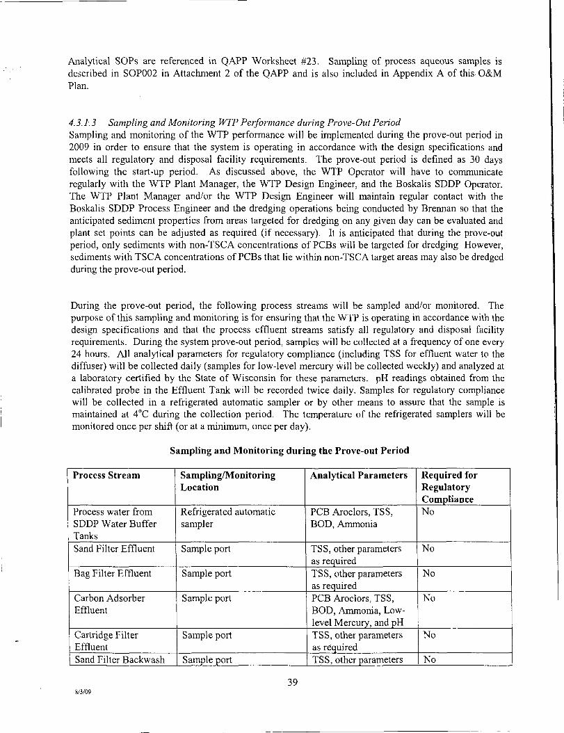
Analytical SOPs are referenced in QAPP Worksheet #23. Sampling of process aqueous samples is described in SOP002 in Attachment 2 of the QAPP and is also included in Appendix A of this O&M Plan.
4.3.1.3 Sampling and Monitoring WTP Perfonnance during Prove-Out Period Sampling and monitoring of the WTP performance will be implemented during the prove-out period in 2009 in order to ensure that the system is operating in accordance with the design specifications and meets all regulatory and disposal facility requirements. The prove-out period is defined as 30 days following the start-up period. As discussed above, the WTP Operator will have to communicate regularly with the WTP Plant Manager, the WTP Design Engineer, and the Boskalis SDDP Operator. The WTP Plant Manager and/or the WTP Design Engineer will maintain regular contact with the Boskalis SDDP Process Engineer and the dredging operations being conducted by Brennan so that the anticipated sediment properties from areas targeted for dredging on any given day can be evaluated and plant set points can be adjusted as required (if necessary). It is anticipated that during the prove-out period, only sediments with non-TSCA concentrations of PCBs will be targeted for dredging However, sediments with TSCA concentrations of PCBs that lie within non-TSCA target areas may also be dredged during the prove-out period.
During the prove-out period, the following process streams will be sampled and/or monitored. The purpose of this sampling and monitoring is for ensuring that the WTP is operating in accordance with the design specifications and that the process effluent streams satisfy all regulatory and disposal facility requirements. During the system prove-out period, samples will be collected at a frequency of one every 24 hours. All analytical parameters for regulatory compliance (including TSS for effluent water to the diffuser) will be collected daily (samples for low-level mercury will be collected weeidy) and analyzed at a laboratory certified by the State of Wisconsin for these parameters. pH readings obtained from the calibrated probe in the Effluent Tank will be recorded twice daily. Samples for regulatory compliance will be collected in a refrigerated automatic sampler or by other means to assure that the sample is maintained at 4°C during the collection period. The temperature of the refrigerated samplers will be monitored once per shift (or at a minimum, once per day).
Sampling and Monitoring during the Prove-out Period
Process Stream
Process water from SDDP Water Buffer Tanks Sand Filter Effluent
Bag Filter Effluent
Carbon Adsorber Effluent
Cartridge Filter Effluent Sand Filter Backwash
Sampling/Monitoring Location
Refrigerated automatic sampler
Sample port
Sample port
Sample port
Sample port
Sample port
Analytical Parameters
PCB Aroclors, TSS, BOD, Ammonia
TSS, other parameters as required TSS, other parameters as required PCB Aroclors, TSS, BOD, Ammonia, Low-level Mercury, and pH TSS, other parameters as required TSS, other parameters
Required for Regulatory Compliance No
No
No
No
No
No
39 8/3/09

to SDDP Overflow Tank Carbon Adsorber Backwash to SDDP Overflow Tank Effluent Water to Diffuser
Effluent Water to Diffuser
Sample port
Refrigerated automatic sampler (subject to WDNR approval for mercury) Read from continuous probe in WTP Effluent Tank
as required
TSS, other parameters as required
PCB Aroclors, TSS, BOD, Ammonia and Low-level Mercury pH
No
Yes
Yes
Sampling Locations and Methods and SOP Requirements are identified in QAPP Worksheet #18. Analytical SOP Requirements are detailed in QAPP Worksheet #19. Field Quality Control Samples are summarized in QAPP Worksheet #20. Project Sampling SOPs are referenced in QAPP Worksheet #21. Analytical SOPs are referenced in QAPP Worksheet #23. Sampling of process aqueous samples is described in SOP002 in Attachment 2 of the QAPP and is also included in Appendix A of this O&M Plan.
4.3.2 Qualitv Control Sample Requirements
QC samples are analyzed for the purpose of assessing the quality of the sampling effort and of the analytical data. QC samples include field QC samples and laboratory QC samples. Field QC samples are described in Section 8.1 of the QAPP and include environmental field duplicate samples, co-located field replicates, equipment rinsate blanks, low-level mercury blanks, and cooler temperature blanks. Laboratory QC samples include method blanks, matrix spike/matrix spike duplicates, surrogate compounds, intemal standards, laboratory control samples, and laboratory duplicate samples. The general information and guidance regarding the different types of field QC samples is provided below. Similar information for laboratory QC samples including their definitions and frequency of collection is provided in Section 8.2 of the QAPP. Field QC samples and their acceptance criteria are summarized in QAPP Worksheet #20. A summary of QC procedures, frequencies, criteria, and corrective actions for the laboratory QC samples, as detemiined by the applicable guidelines is provided in QAPP Worksheet #28.
4.3.2.1 Environmental Field Duplicate Samples Field duplicates are used to monitor the precision of the field sampling procedures and the variability of sample data. Aqueous field duplicates are field split samples collected by mixing enough process water volume for two samples. Field duplicates will typically be collected and analyzed at a frequency of 1 for every 20 samples (approximately 5 percent); exceptions to this rate are noted on QAPP Worksheet #20. Field duplicates will only be collected for the Effluent Water that is analyzed for regulatory purposes. Field duplicates will be analyzed for the same parameters, as applicable, as the original samples.
4.3.2.2 Equipment Rinsate Blanks
Equipment rinsate blanks are used to monitor cleanliness of the sampling equipment and the effectiveness of the decontamination procedures. Dedicated sampling equipment will be used during the project to the extent possible, reducing the need and frequency of equipment rinsate blanks. As required, equipment rinsate blanks will be collected once per week (assuming 6-day work week) and sent to the off-site laboratory for analysis of the same parameters (chemical only) as the original samples.
40 8/3/09
4.3.2.3 Low-level Mercuiy Blanks
Initially, during a one month period, both daily composite and grab samples will be collected for low level mercury analysis for comparison purposes. If the WDNR agrees the results are comparable, grab sampling will be discontinued and only daily composite samples for low-level mercury will be collected once per week using a dedicated refrigerated automatic sampler. Alternatively, weekly composite mercury samples may be collected using the dedicated refrigerated automatic sampler, subject to the approval of the WDNR. Glassware will be borosilicate glass that is either purchased in that condition or cleaned at the ultra low-level by the mercury laboratory. To monitor the composite sampling process and determine the potential for introduced contamination, low level mercury blanks will be collected using ultra-pure reagent water supplied by the mercury laboratory as required by WDNR. The procedure for collecting these blanks will mirror the procedure for sample collection as closely as possible, including remaining in the sampler for the same duration with the same degree of cover or cap. Low level mercury blanks will be collected over each daily composite sampling event (typically collected from 0700 on Thursdays to 0700 on Fridays).
4.3.2.3.a Grab Sampling Blanks - Tetra Tech will collect a grab sampling blank" along with each grab sample. This blank will be an aliquot of ultra-pure reagent water that is shipped from the laboratory to the facility, and then comes in contact with sampling devices, exposure to site conditions, storage requirements, preservation, and analytical procedures the same as the regular grab sample. Therefore, for every regular low-level mercury sample collected via grab, there will also be one grab sampling blank.
4.3.2.3.b Composite Sampling Blanks - When using the ISCO auto sampler, Tetra Tech will collect a composite sampling blank" along with each composite sample. This blank will monitor the composite sampling process and determine the potential for introduced contamination. The blanks are collected using ultra-pure reagent water supplied by the laboratory, that is put into a bottle in the ISCO auto sampler at the beginning of the daily event and then goes through (approximately) the same process as the regular composite sample. At the end of the 24 hour period, this blank is removed from the ISCO sampler (the same as the regular composite sample), and shipped to the laboratory for analysis. Therefore, for every regular low-level mercury sample collected via the composite sampler, there will also be one composite sampling blank.
4.3.2.3.C Field Duplicates - Tetra Tech will collect a field duplicate pair for QC purposes every 10 project samples. This will be used to monitor the precision of the field sampling procedures and the variability of the sample data. The volume of effluent water in the ISCO auto sampler, when we begin using it, will be separated into 2 sets of sample containers and then analyzed as separate samples at the laboratory.
4.3.2.4 Cooler Temperature Blanks Temperature blanks are used to monitor the receipt temperature of the samples upon arrival at the analytical laboratory. Temperature blanks will consist of an unpreserved 40-milliliter glass or plastic vial filled with tap water. A temperature blank must be included in each sample container sent to an analytical laboratory. However, Wisconsin regulations include provisions for omitting sample receipt temperature at the laboratory if the samples are received on ice.
4.3.3 Equipment Decontamination Procedures
For this sampling and analysis program, both disposable and non-disposable sampling equipment may be used. All non-disposable sampling equipment will be decontaminated prior to collecting each sample. The following sequence will be used:
41 8/3/09

Remove all visible contaminants using laboratory detergent and potable water.
Rinse with potable water.
Rinse with deionized water.
Rinse organic sampling equipment with hexane. Then rinse with deionized water again.
For sampling equipment used for low-level mercury analysis, the more stringent decontamination procedures provided by the USGS Wisconsin District Mercury Laboratory will be followed. These are described in Appendix B of SOP002. In accordance with QAPP Worksheet #20, one field equipment (or rinsate) blank will be collected following every ten low-level mercury samples. Please refer also to SOP-003 in the QAPP.
Decontamination fluids generated will be collected and stored on site for later disposal as specified in the Transportation/Disposal Plan.
4.3.4 Sample Identification. Documentation, Chain of Custody. Packaging, and Shipping Identification, documentation and strict custody of samples are important for ensuring the integrity of the environmental samples and maintaining data quality. The subsections below and QAPP Worksheets #26 and #27 address sample identification, packaging, shipping, and documentation.
4.3.4.1 Sample Identification and Labeling Samples collected from the WTP will be uniquely identified. Each sample will be denoted with an identification code as to the process stream (i.e., the location of sampling and type of material being sampled). These codes are outlined in the table below. The year of the sampling (e.g., "09") will then be added to the identification to segregate different process sampling events along with a sequential number.
Process Stream Location/Material Code
Process water from SDDP Water Buffer Tanks PW
Sand Filter Effluent SEE
Bag Filter Effluent BGE
Carbon Adsorber Effluent CAE
Cartridge Filter Effluent CFE
Sand Filter Backwash to SDDP Overflow Tank SFB
Carbon Adsorber Backwash to SDDP CAB
Overflow Tank
Effluent Water to Difftiser EFF
Midpoint of GF1-GF2 Dual Unit MP 1
Midpoint of GF3-GF4 Dual Unit MP3
Midpoint of GF5-GF6 Dual Unit MP5
Midpoint of GF7-GF8 Dual Unit MP7
Midpoint of GF9-GF10 Dual Unit MP9
Midpoint ofGFll-GF12 Dual Unit MP 11
42 8/3/09

Midpoint ofGF13-GF14 Dual Unit MP13
Midpoint ofGF15-GFl6 Dual Unit MP15
Midpoint of GF17-GF18 Dual Unit MP 17
For example, a WTP effluent sample would be denoted as "TTFR-EFF-09-XXXX."
Sample labels will be completed by field persormel. Labels will include the project identification, sample identification, date and time of sampling, sampler, analyses to be performed on the specific sample bottle, type of sample (grab or composite) and preservative (if applicable). Each sample label will be filled out completely with indelible ink.
4.3.4.2 Sample Documentation
The sampling team or any individual performing a particular field investigation activity will be required to maintain a field logbook. Each logbook will be controlled and assigned a unique sequential identification by the Field Team Lead (e.g., the second logbook devoted to the WTP sampling activities may be designated "WTP Sampling Logbook No. 2"). In addition, a list of field logbooks will be maintained by the Field Team Lead, and will include the name of the logbook, purpose, person to whom assigned (i.e., name of task lead), date assigned, and date retumed to the Field Team Lead.
The field logbook will be a bound weatherproof notebook, and entries to the logbook must be filled out legibly in black waterproof ink. Pertinent information to be recorded in field logbooks includes all information that is necessary to reconstruct the investigative/sampling operations. Documentation of sample activities in the field logbook will be completed immediately after sampling at the location of sample collection. Logbook entries will contain all sample information, including sample number, collection time, location, descriptions, field measurements, and other site- or sample-specific observations. Difficuhies with recovery and field observations (e.g., staining, visible contamination, etc.) must be noted if encountered. Any additional information, such as generated instrument output, will be attached into the field logbook with clear tape in the order of generation or will be filed in a specific folder for inclusion with project files.
Logbook pages (for both the master site logbook and the field logbooks) will have the name of the Site and a description of the location/activity discussed, as well as the calendar date, written on the top of each page. Logbook pages will be consecutively numbered, and upon entry of data, the logbook pages require the date and the signature of the responsible project team member at the bottom of each page. Corrections to the logbooks will consist of a single strike line through the incorrect entry, the new accurate information, the initials of the corrector, and the date of amendment. Any blank spaces/pages in the logbooks will be crossed out with a single strike mark and signed by the person making the notation.
4.3.4.3 Sample Chain of Custody
Sample custody must be strictly maintained and carefully documented each time the sample material is collected, transported, received, prepared, and analyzed. Custody procedures are necessary to ensure the integrity of the samples, and samples collected during the field investigation must be traceable from the time the samples are collected until they are disposed of and/or stored, and their derived data are used in the final report.
A sample is considered under custody if it is/was:
• In a sampler's possession;
43 8/3/09

• In a sampler's view after being in his/her possession; • In a sampler's possession and locked up in a secured container; or • In a designated secure area.
Persormel collecting samples are responsible for the care and integrity of those samples until they are properly transferred or dispatched. Therefore, the number of people handling a sample will be kept to a minimum.
Chain of Custody (COC) records will be completed by the sampler and shall accompany the samples at all times. The following information shall be indicated on the COC record:
• Project identification; • Signature of samplers; • Sample identification, sample matrix, date and time of collection, grab or composite
sample designation, number of containers corresponding to that sample identification, analyses required, remarks or sample location (if applicable), and preservation method(s);
• Signature of the individual relinquishing the samples; and • Name of the individual(s) receiving the samples and air bill number, if applicable.
The COC preparer will then check the sample label and COC record for accuracy and completeness.
4.3.4.4 Sample Tracking
When transferring custody of samples, individuals relinquishing custody and individuals receiving custody will sign, date, and record the time on the COC. When samples are being shipped to the laboratory via courier, the COC record will be signed as "receiver" by the courier when he/she accepts possession of the samples, and a signed copy will be retained by the Tetra Tech Team. For samples transported by an overnight shipping company (e.g.,Federal Express), the shipping company will be indicated as receiving custody. Upon receipt of shipment at the laboratory, a designated sample custodian will accept custody of the samples and verify that information on the sample labels matches the COC record. Pertinent information on shipment, air bill number, pickup, courier, date, and time will be recorded on the COC. It is then the laboratory's responsibility to maintain logbooks and custody records throughout sample preparation and analysis.
4.3.4.5 Sample Packaging and Shipping
Samples for off-site laboratory analysis will be shipped via Federal Express or by courier for overnight delivery in waterproof coolers using the procedures outlined below. The samples taken for this project shall be considered low-level or environmental samples for packaging and shipping purposes. Prior to packing and shipping, as applicable, samples will be stored on ice. The sample packing procedures are as follows:
• After filling out the pertinent information on the sample label, if necessary cover the label with clear tape.
• Place about 3 inches of inert cushioning material, such as bubble wrap, in the bottom of the cooler.
• • Place containers upright in the cooler in such a way that they will not touch during shipment.
44 8/3/09
• Put in additional inert packing material to partially cover the sample containers (more than halfway).
• Place ice, when necessary, sealed in plastic bags, around and on top of the containers. As applicable to specific analyses (outlined in Worksheet #19 of the QAPP), the temperature of the samples shall be maintained at or below 4 °C during shipment to the laboratory. The addition of ice will not be necessary for those parameters that do not require cooling as a preservation technique
• Fill cooler with cushioning material. • Tape the drain on the cooler shut.
If the samples are sent directly via courier service from the Site to a local laboratory certified by the State of Wisconsin, the COC record will not be placed inside the cooler. The sample cooler(s) will be secured, with signed and dated custody seals affixed over the lid opening in at least two locations, and the cooler wrapped with strapping tape (without obscuring the custody seals). Orientation "this end up" arrows will be drawn or attached on two sides of the cooler. The COC record will be signed by the receiver (e.g., the courier, the laboratory sample custodian) when he/she accepts possession of the samples, and a signed copy will be retained by the Tetra Tech Team.
For samples being shipped by an overnight delivery service to a laboratory certified by the State of Wisconsin, the COC record will be placed in a waterproof plastic bag and taped with masking tape to the inside lid of the cooler. The cooler lid will be secured with strapping/shipping tape (wrap the cooler completely with tape at a minimum of two locations), and a completed shipping label will be attached to the top of the cooler. Orientation "this end up" arrows will be drawn or attached on two sides of the cooler. Two signed and dated custody seals will be placed on opposite comers of the cooler so that the cooler cannot be opened without breaking the seals.
4.4 Laboratory Analytical Procedures and Requirements
4.4.1 Analytical Procedures
As stated previously, samples will be analyzed in strict accordance with the analytical test methods and procedures in NR 219, utilizing approved USEPA and ASTM methods. The anticipated number of samples, analytical methods, and number of QC samples are identified in Section 4.3.1 and the QAPP Worksheets identified above.
Analytical methods selected for the Site will provide results with detection limits sufficiently below designated action levels, and the methods will be accurate enough to quantify contamination at concentrations below action levels.
4.4.2 Laboratory Reporting Requirements
Laboratory reports will include a full data package in order to support QA/QC review. Reporting requirements will include, but are not limited to the following:
• The name, address, and phone number of the analytical laboratory.
45 8/3/09

Signature of an authorized laboratory individual, indicating the acceptability of the data.
A copy of signed chain of custody forms, indicating the condition of samples at the time of receipt by the laboratory.
Sample results reported in units of g or mg per liter or kg. Results will be reported on a dry weight basis and will include correction for dilution/concentration factors.
Sample results will include a summary of pertinent chain of custody and tracking information (i.e., dates of preparation and analysis, analytical instmmentation, calibration information, associated QC samples, etc.). Other raw data including chromatograms must be on file at the laboratory and available for review upon request.
Quality control results reported are to include spiking concentrations and acceptable limits. QC results that exceeded criteria and corrective actions should be discussed by the laboratory.
4.4.3 Data Review
All data will be reviewed by laboratory QC personnel prior to submittal to Tetra Tech and Boskalis. In addition, the Tetra Tech chemistry staff will perfomi a review of QA/QC data for all sample analysis results. After these reviews, the data will be provided to the Tetra Tech personnel who are responsible for monitoring the performance of the WTP operation. They will utilize the analytical results to verify that the plant is operating in the normal expected range of operation for each variable reported.
46 8/3/09

The review will include the following:
• Review of chain-of-custody and sample receipt documents to verify sample identities.
• Review of sample log-in documents to verify any potential problems with sample custody, integrity, preservation, labeling, etc.
• Review of field blank data to ascertain any problems with container or preservative contamination, or field contamination.
• Review of method blank data to determine the presence and approximate concentration of sources of contamination in the analytical process.
• Review of matrix spike data as a measure of matrix effects and analytical precision.
• Review of field and laboratory duplicate data as a measure of sampling technique applicability, homogeneity, and analytical precision.
• Review of standard reference material or laboratory control sample data as a measure of analytical accuracy. Data will be compared to the certified acceptable ranges of analytical values.
• Review of sample dates, extraction/digestion dates, and analysis dates to determine whether maximum holding times were met or exceeded.
Where appropriate, data qualifiers will be incorporated into certain data summary tables generated for this project. A brief summary of the data QA/QC review will be included in the final report.
47 8/3/09

5.0 HEALTH AND SAFETY
5.1 Introduction
All activities performed at the WTP are govemed by the Site Health and Safety Plan (SHSP). The SHSP presents procedures to be followed by Tetra Tech and its subcontractors (including Boskalis) and all other on-site personnel in order to avoid and, if necessary, protect against health and/or safety hazards. The SHSP is designed to protect on-site personnel and area residents from physical, chemical, and all other hazards posed by activities conducted as part of the Phase 2B Work conducted at the Site. The SHSP takes into account the hazards inherent to the planned constmction/marine activities. In addition, Section 10.0 of the SHSP includes the Emergency Response and Contingency Plan for the Phase 2B activities as required by the Administrative Order. The SHSP will comply with applicable parts of Occupational Safety and Health Administration (OSHA) Regulations, primarily 29 CFR Parts 1910 and 1926, and Tetra Tech's Environmental Health and Safety (EHS) Program. In addition, since the majority of site activities are being performed on or adjacent to water, they must also comply with 29 CFR 1917 Marine Terminals and the US Coast Guard Regulations. Many programs from the EHS Program are referenced in the SHSP and are included in the appendices. Modifications to the SHSP may be made with the approval of the Project Environmental and Safety Manager (PESM) for this project using the Field Change Request Form found in Appendix A of the SHSP.
5.2 Summary of Major Risks
Work near the river. Heavy equipment hazards. Slips, Trips, and Falls. Exposure to PCBs. Rotating machinery Electrical hazards Pressurized air and process water pipelines and process equipment
5.3 Zero Incident Performance
Zero Incident Performance (ZIP) describes Tetra Tech's approach and expectations for both safety and project execution. Tetra Tech will achieve this level of performance excellence through teamwork and partnering with our client and our Subcontractors, and through the participation of every person on this project.
We (Tetra Tech and our client) believe that: • All incidents are preventable through proper plarming, tasking, and execution of plans as wriften. • Any goal besides Zero Incident Performance is unacceptable and sends the message that
incidents cannot be prevented and that losses are tolerated. Incidents are defmed as OSHA recordables, property damage cases, fires, explosions, spills or releases to the environment and safety-related work stoppages. In addition, an incident includes an event which could have resulted in one of these outcomes had the circumstances been different ("near miss").
• Active participation by all personnel is required to achieve Zero Incident Performance. This includes Tetra Tech, the client, and all Subcontractor personnel.
• Each person on this project is individually responsible and accountable for their safety performance.
• If anv incident does occur, it must be reported and investigated to identify root causes, take corrective actions, and communicate the lessons learned.
48 8/3/09
All Tetra Tech and Subcontractor personnel will sign a ZIP pledge poster affirming their belief in and commitment to ZIP. The ZIP Barmer will be posted conspicuously at the project site and the hours worked without a loss time incident will also be posted. The Tetra Tech EHS will continually evaluate planning and project execution to ensure that ZIP is embedded in the work process. In addition, awareness programs are utilized to assist in implementation of Tetra Tech's ZIP initiative.
A Subcontractor, after award of a contract, shall be required to attend a pre-constmction Health and Safety Orientation meeting. This meeting will involve the Subcontractor's key personnel, and will cover such items as ZIP expectations and the Employee Participation Progi am (EPP).
5.4 Activity Hazard Analyses
The Activity Hazard Analysis (AHA) is a systematic way of identifying the potential health and safety hazards associated with major phases of work on the project and the methods to avoid, control and mitigate those hazards. The AHAs follow the guidance of the Tetra Tech Corporate Program EHS 3-5. AHAs are developed for all activities and will be used to train workers in proper safety procedures during phase preparatory meetings.
AHAs for 2009 and subsequent years' site activities are included in Appendix C of the SHSP. AHAs that are applicable to activities at the WTP and adjacent areas include:
General Site Hazards Dewatering Operations Transportation and Disposal Wastewater Treatment Plant Operations Sampling (Sediments and Process Operations)
5.5 Personal Protective Equipment
The personal protective equipment specified in Table 5-1 of the SHSP represents the initial level of PPE selection for each activity required by 29 CFR 1910.132. Specific information on the selection rationale for each activity can be found in the Activity Hazard Analyses. Personal protective equipment selection shall be made by the ESS and approved by the PESM. Additional tasks not included in Table 5-1 of the SHSP shall be reviewed by the ESS and PESM.
Due to the nature of the activities it is not anticipated that upgrading to Level C or B will be required during the Lower Fox River site activities. Level D or modified Level D is anticipated for all site work but the ESS has the responsibility for monitoring site and work conditions and deciding the appropriate level of protection based on indications of potential exposure.
49 8/3/09

6.0 PROCESS DESCRIPTION AND OPERATION
The process descriptions for the LFR WTP, provide the written narrative which explains the individual system loops and their inter-relationship. They were used to program the Computer Monitoring and Control System (CMCS) by describing the setpoints and relationships between the process equipment and the instmmentation used for monitoring the water treatment process. The process loops are shown in Table 6-1 and the functional descriptions are provided in the following sections.
Table 6-1 Treatment Process Loops
SYSTEM No. 1 2 3 4 5 6 7 8 9
TITLE Influent Process Water (wastewater) from SDDP Multi-media Sand Filtration Bag Filtration Granular Activated Carbon Adsorption Cartridge Filtration Treated Effluent to Multi-port Diffuser Backwash Water Compressed Air Generation Building Sump and Sand-trap Sump
6.1 Process Loop # 1 - Influent Process Water (wastewater) from SDDP
This process loop corresponds to P&ID P-103. The major equipment for this process loop is listed in Section 6.1.1, the instmmentation and controls and the functional description are included in Section 6.1.2 and the process interlocks are listed in Section 6.1.3.
6.1.1 Major Equipment
yiirag.l^jimher,s^ WBTl WBT2 P-IA P-IB P-IC
20"-GV-WBTl 20"-GV-WBT2
18"-BFV-1A 10"-BFV-2A 10"-CV-1A 18"-BFV-1B 10"-BFV-2B 10"-CV-1B 18"-BFV-1C 10"-BFV-2C 10"-CV-1C
1"-BV-303A
mmmmmmmmm i mmi Water Buffer Tank 1 (in Boskalis SDDP) Water Buffer Tank 2 (in Boskalis SDDP) Process Pump lA Process Pump 1B Process Pump IC Ouflet Valve from WBTl Outlet Valve from WBT2 Isolation Valve Process Pump 1A Isolation Valve Process Pump 1A Check Valve Process Pump 1A Isolation Valve Process Pump IB Isolation Valve Process Pump IB Check Valve Process Pump IB Isolation Valve Process Pump IC Isolation Valve Process Pump IC Check Valve Process Pump 1C Isolation Valve Process Pump 1A Pressure Gauge
50 8/3/09

1"-BV-303B
1"-BV-303C
1"-BV-INF1 1"-BV-INF2 1"-BV-SP1
Isolation Valve Process Pump IB Pressure Gauge Isolation Valve Process Pump 1C Pressure Gauge Isolation Valve Automatic Sampler Drain Valve Automatic Sampler
6.1.2 System Functional Description
Process water (wastewater) from the SDDP will be collected in two tanks provided by Boskalis, Water Buffer Tank 1 and Water Buffer Tank 2 and pumped from Water Buffer Tank 1 to the Multi-media Sand Filters via three Process Water Pumps, P-IA, P-IB, and P-IC, which will be equipped with variable frequency drives (VFD). Any two pumps will be used to transfer the process water at any given time and the third pump will serve as a spare. Measurement signals of level, pH, and flow rate will be indicated and transmitted to the programmable logic controller (PLC) and displayed and recorded on the human machine interface (HMl) screens. Based on pre-selected high and low level set points, the PLC will send signals to corresponding switches to start and stop the process water pumps, and the corresponding high and low level alarms will be displayed on the HMl screens. The PLC will also send start-stop and speed control signals to the VFD and the corresponding speed and mn indications will be displayed on the HMl screens.
The influent flow rate of process water to the multi-media sand filters will be measured by the magnetic flow meter FE-304, transmitted by FIT-304 and the total flow will be recorded by FQIT-304. The process water level in Water Buffer Tank 1 will be measured by LE-301 and transmitted by LIT-301 and the low-low level and high-high level in the tank will be controlled by level switches, LSLL-301 and LSHH-301, respectively. The pH of the process water in Water Buffer Tank 1 will be measured by AE-301 and transmitted by AIT-301. The process water level in Water Buffer Tank 1 will be monitored and controlled at the Operator-selected level by LIC-301 by adjusting the speed of the three pumps. Each of the three pumps will be equipped with Hand-Off-Auto selector switches, HOA-302A, HOA-302B, and HOA-302C. In the Hand position, the pumps will be kept miming and the normal start-stop interlocks will be by-passed. In the Off position, the pumps will be de-energized. In the Auto position, the pumps will be started automatically on high process water level LSH-301 and stopped automatically on low process water level LSL-301 in Water Buffer Tank 1. Each of the three pumps will also be equipped with a speed indicator controller and a motor mn indicator. A low-low process water level in Water Buffer Tank 1 or a high-high treated water level in the Effluent Tank or a high-high water level in the Building Sump or a plant shutdown signal will also shut down the Process Water Pumps.
Instmmentation and controls associated with the Influent Process Water (wastewater) from SDDP Process Loop are summarized in the following table:
!5:y l&!H»tisfciftCQntrolf fei> ^ ^ Level Switch LSLL-301 Level Alarm LALL-301 Level Switch LSHH-301 Level Alarm LAHH-3 01 Level Element LE-301 Level Indicator Transmitter LIT-301 Level Alarm LAL-301
Setpomt 4ft 4ft 11 ft 11 ft
7.5 ft
5ft
Indicates low-low level in Water Buffer Tank 1 Alarms low-low level in Water Buffer Tank 1 Indicates high-high level in Water Buffer Tank 1 Alarms high-high level in Water Buffer Tank 1 Measures water level in Water Buffer Tank 1 Indicates and transmits water level in Water Buffer Tankl Alarms low level in Water Buffer Tank 1
51 8/3/09

Level Alarm LAH-301 pH Element AE-301 pH Indicator Transmifter AIT-301
pH Alarm AAL-3 01 pH Alarm AAH-301 Hand Switch HOA-302A
Run hidicator MI-302A Speed Indicator Controller SIC-302A Pressure Indicator P1-303A Hand Switch HOA-302B
Run hidicator MI-302B Speed Indicator Controller SIC-302B Pressure hidicator PI-303B Hand Switch HOA-302C
Run Indicator MI-302C Speed Indicator Controller SIC-302C Pressure hidicator PI-303C Flow Element-FE-304
Flow Indicator Transmitter FIT-304 Flow Quantity Indicator Transmitter FQIT-304
10ft
7.5 pH
6pH 9pH . HAND • . OFF . AUTO
. HAND
. OFF
. AUTO
. HAND • . OFF . AUTO
Alarms high level in Water Buffer Tank 1 Measures pH of water in Water Buffer Tank 1 Indicates and transmits pH of water in Water Buffer Tankl Alarms low pH of water in Water Buffer Tank 1 Alarms high pH of water in Water Buffer Tank 1
Manual operation Pump P-l A mrming, normal start-stop interlocks bypassed Pump P-l A de-energized Pump P-l A starts automatically on high level LAH-301 and stops automatically on low level LAL-301
Indicates Pump P-l A is mnning Indicates and controls speed of Pump P-l A
Indicates pressure in Pump P-l A discharge Manual operation Pump P-IB mnning, normal start-stop interlocks bypassed Pump P-IB de-energized Pump P-IB starts automatically on high level LAH-301 and stops automatically on low level LAL-301
Indicates Pump P-lB is mnning Indicates and controls speed of Pump P-IB
Indicates pressure in Pump P-IB discharge Manual operation Pump P-IC mnning, normal start-stop interlocks bypassed Pump P-1C de-energized Pump P-1C starts automatically on high level LAH-301 and stops automatically on low level LAL-301
Indicates Pump P-lC is mnning Indicates and controls speed of Pump P-IC
Indicates pressure in Pump P-IC discharge Measures process water flow rate to Multi-media Sand Filters Indicates and transmits process water flow rate to Muhi-media Sand Filters Indicates and transmits total process water flow rate to MuUi-media Sand Filters
6.1.3 Interlock Summary
Low-low process water level in Water Buffer Tank 1 High-high treated water level in Effluent
Tbterlbck 1-301
1-701
mmmmMmmmmmmmmmm. De-energizes Pumps P-IA, P-IB, P-IC
De-energizes Pumps P-IA, P-IB, P-IC
8/3/09
52
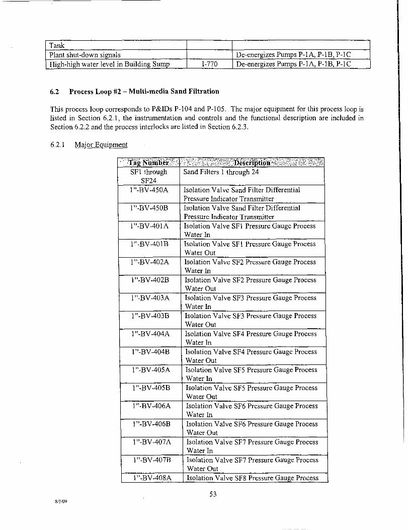
Tank
Plant shut-down signals
High-high water level in Building Sump 1-770
De-energizes Pumps P-l A, P-IB, P-IC De-energizes Pumps P-l A, P-IB, P-IC
6.2 Process Loop #2 - Multi-media Sand Filtration
This process loop corresponds to P&IDs P-104 and P-105. The major equipment for this process loop is listed in Section 6.2.1, the instmmentation and controls and the functional description are included in Section 6.2.2 and the process interlocks are listed in Section 6.2.3.
6.2.1 Major Equipment
••':VTa«:Mplirf;' SFl through
SF24 1".BV-450A
1"-BV-450B
1".BV-401A
1"-BV-401B
1"-BV-402A
1".BV-402B
1".BV-403A
1".BV-403B
1".BV-404A
1".BV-404B
1".BV-405A
1"-BV-405B
1"-BV-406A
1"-BV-406B
1".BV-407A
1".BV-407B
1".BV-408A
••;;• hx f;'? iv4\ i';:f'fe;'?H i-Description Sand Filters 1 through 24
Isolation Valve Sand Filter Differential Pressure Indicator Transmitter Isolation Valve Sand Filter Differential Pressure Indicator Transmitter Isolation Valve SFl Pressure Gauge Process Water hi Isolation Valve SFl Pressure Gauge Process Water Out Isolation Valve SF2 Pressure Gauge Process Water hi Isolation Valve SF2 Pressure Gauge Process Water Out Isolation Valve SF3 Pressure Gauge Process Water hi Isolation Valve SF3 Pressure Gauge Process Water Out Isolation Valve SF4 Pressure Gauge Process Water hi Isolation Valve SF4 Pressure Gauge Process Water Out Isolation Valve SF5 Pressure Gauge Process Water hi Isolation Valve SF5 Pressure Gauge Process Water Out Isolafion Valve SF6 Pressure Gauge Process Water hi Isolation Valve SF6 Pressure Gauge Process Water Out Isolation Valve SF7 Pressure Gauge Process Water hi Isolation Valve SF7 Pressure Gauge Process Water Out Isolation Valve SF8 Pressure Gauge Process
8/3/09
53

l ' ' .BV-408B
l"-BV-409A
1"-BV-409B
1"-BV-410A
1"-BV-410B
1"-BV-411A
1"-BV-411B
r '-BV-412A
1"-BV-412B
1"-BV-413A
1"-BV-413B
1"-BV-414A
1"-BV-414B
1"-BV-415A .
1"-BV-415B
1"-BV-416A
1"-BV-416B
r '-BV-417A
1"-BV-417B
]"-BV-418A
1"-BV-418B
1"-BV-419A
1".BV-419B
1"-BV-420A
Water hi
Isolation Valve SF8 Pressure Gauge Process Water Out
Isolation Valve SF9 Pressure Gauge Process Water hi
Isolation Valve SF9 Pressure Gauge Process Water Out
Isolation Valve SFIO Pressure Gauge Process Water hi
Isolation Valve SFIO Pressure Gauge Process Water Out
Isolation Valve SFl 1 Pressure Gauge Process Water hi
Isolation Valve SFl 1 Pressure Gauge Process Water Out Isolation Valve SFl2 Pressure Gauge Process Water hi Isolation Valve SFl2 Pressure Gauge Process Water Out
Isolation Valve SFl3 Pressure Gauge Process Water hi
Isolation Valve SFl 3 Pressure Gauge Process Water Out Isolation Valve SFl4 Pressure Gauge Process Water hi Isolation Valve SFl4 Pressure Gauge Process Water Out Isolation Valve SFl5 Pressure Gauge Process Water hi Isolation Valve SFl5 Pressure Gauge Process Water Out Isolation Valve SFl6 Pressure Gauge Process Water hi Isolation Valve SFl 6 Pressure Gauge Process Water Out Isolation Valve SFl 7 Pressure Gauge Process Water hi Isolation Valve SFl 7 Pressure Gauge Process Water Out
Isolation Valve SFl 8 Pressure Gauge Process Water hi Isolation Valve SFl 8 Pressure Gauge Process Water Out
Isolation Valve SFl 9 Pressure Gauge Process Water hi
Isolation Valve SFl9 Pressure Gauge Process Water Out Isolation Valve SF20 Pressure Gauge Process Water hi
8/3/09 54
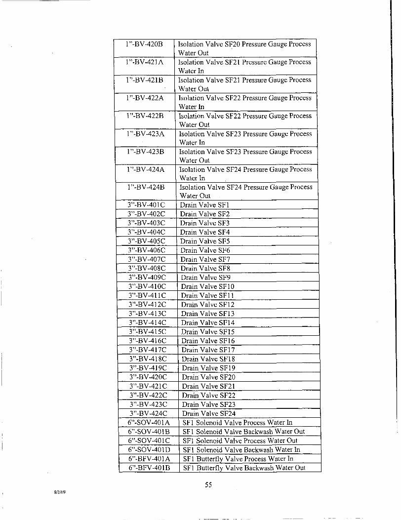
1"-BV-420B
1"-BV-421A
1"-BV-421B
1"-BV-422A
1"-BV-422B
1"-BV-423A
1"-BV-423B
1"-BV-424A
1"-BV-424B
3".BV-401C 3".BV-402C 3".BV-403C 3".BV-404C 3".BV-405C 3".BV-406C 3".BV-407C 3"-BV-408C 3"-BV-409C 3"-BV-410C 3"-BV-411C 3"-BV-412C 3"-BV-413C 3".BV-414C 3"-BV-415C 3"-BV-416C 3"-BV-417C 3"-BV-418C 3"-BV-419C 3"-BV-420C 3"-BV-421C 3"-BV-422C 3"-BV-423C 3"-BV-424C
6"-SOV-401A 6"-SOV-401B 6"-SOV-401C 6"-SOV-401D 6"-BFV-401A 6"-BFV-401B
Isolation Valve SF20 Pressure Gauge Process Water Out Isolation Valve SF21 Pressure Gauge Process Water hi Isolation Valve SF21 Pressure Gauge Process Water Out Isolation Valve SF22 Pressure Gauge Process Water hi Isolation Valve SF22 Pressure Gauge Process Water Out Isolation Valve SF23 Pressure Gauge Process Water hi Isolation Valve SF23 Pressure Gauge Process Water Out Isolation Valve SF24 Pressure Gauge Process Water In Isolation Valve SF24 Pressure Gauge Process Water Out Drain Valve SFl Drain Valve SF2 Drain Valve SF3 Drain Valve SF4 Drain Valve SF5 Drain Valve SF6 Drain Valve SF7 Drain Valve SF8 Drain Valve SF9 Drain Valve SFIO Drain Valve SFl 1 Drain Valve SFl2 Drain Valve SFl3 Drain Valve SFl4 Drain Valve SFl5 Drain Valve SFl6 Drain Valve SFl 7 Drain Valve SFl 8 Drain Valve SFl 9 Drain Valve SF20 Drain Valve SF21 Drain Valve SF22 Drain Valve SF23 Drain Valve SF24 SFl Solenoid Valve Process Water In SFl Solenoid Valve Backwash Water Out SFl Solenoid Valve Process Water Out SFl Solenoid Valve Backwash Water hi SFl Butterfly Valve Process Water hi SFl Butterfly Valve Backwash Water Out
8/3/09 55
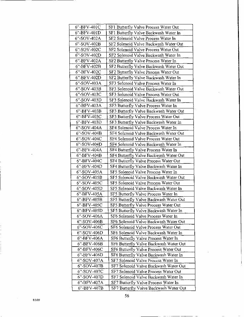
6"-BFV-401C 6"-BFV-401D 6"-SOV-402A 6"-SOV-402B 6"-SOV-402C 6"-SOV-402D 6"-BFV-402A 6"-BFV-402B 6"-BFV-402C 6"-BFV-402D 6"-SOV-403A 6"-SOV-403B 6"-SOV-403C 6"-SOV-403D 6"-BFV-403A 6"-BFV-403B 6"-BFV-403C 6"-BFV-403D 6"-SOV-404A 6"-SOV-404B 6"-SOV-404C 6"-SOV-404D 6"-BFV-404A 6"-BFV-404B 6"-BFV-404C 6"-BFV-404D 6"-SOV-405A 6"-SOV-405B 6"-SOV-405C 6"-SOV-405D 6"-BFV-405A 6"-BFV-405B 6"-BFV-405C 6"-BFV-405D 6"-SOV-406A 6"-SOV-406B 6"-SOV-406C 6"-SOV-406D 6"-BFV-406A 6"-BFV-406B 6"-BFV-406C 6"-BFV-406D 6"-SOV-407A 6"-SOV-407B 6"-SOV-407C 6"-SOV-407D 6"-BFV-407A 6"-BFV-407B
SFl Butterfly Valve Process Water Out SFl Butterfly Valve Backwash Water hi SF2 Solenoid Valve Process Water hi SF2 Solenoid Valve Backwash Water Out SF2 Solenoid Valve Process Water Out SF2 Solenoid Valve Backwash Water hi SF2 Butterfly Valve Process Water hi SF2 Butterfly Valve Backwash Water Out SF2 Butterfly Valve Process Water Out SF2 Butterfly Valve Backwash Water hi SF3 Solenoid Valve Process Water In SF3 Solenoid Valve Backwash Water Out SF3 Solenoid Valve Process Water Out SF3 Solenoid Valve Backwash Water In SF3 Butterfly Valve Process Water hi SF3 Butterfly Valve Backwash Water Out SF3 Butterfly Valve Process Water Out SF3 Butterfly Valve Backwash Water hi SF4 Solenoid Valve Process Water In SF4 Solenoid Valve Backwash Water Out SF4 Solenoid Valve Process Water Out SF4 Solenoid Valve Backwash Water hi SF4 Butterfly Valve Process Water hi SF4 Butterfly Valve Backwash Water Out SF4 Butterfly Valve Process Water Out SF4 Butterfly Valve Backwash Water hi SF5 Solenoid Valve Process Water In SF5 Solenoid Valve Backwash Water Out SF5 Solenoid Valve Process Water Out SF5 Solenoid Valve Backwash Water In SF5 Butterfly Valve Process Water hi SF5 Butterfly Valve Backwash Water Out SF5 Butterfly Valve Process Water Out SF5 Butterfly Valve Backwash Water hi SF6 Solenoid Valve Process Water In SF6 Solenoid Valve Backwash Water Out SF6 Solenoid Valve Process Water Out SF6 Solenoid Valve Backwash Water In SF6 Butterfly Valve Process Water hi SF6 Butterfly Valve Backwash Water Out SF6 Butterfly Valve Process Water Out SF6 Butterfly Valve Backwash Water hi SF7 Solenoid Valve Process Water In SF7 Solenoid Valve Backwash Water Out SF7 Solenoid Valve Process Water Out SF7 Solenoid Valve Backwash Water In SF7 Butterfly Valve Process Water hi SF7 Butterfly Valve Backwash Water Out
8/3/09 56

6"-BFV-407C 6"-BFV-407D 6"-SOV-408A 6"-SOV-408B 6"-SOV-408C 6"-SOV-408D 6"-BFV-408A 6"-BFV-408B 6"-BFV-408C 6"-BFV-408D 6"-SOV-409A 6"-SOV-409B 6"-SOV-409C 6"-SOV-409D 6"-BFV-409A 6"-BFV-409B 6"-BFV-409C 6"-BFV-409D 6"-SOV-410A 6"-SOV-410B 6"-SOV-410C 6"-SOV-410D 6"-BFV-410A 6"-BFV-410B 6"-BFV-410C 6"-BFV-410D 6"-SOV-411A 6"-SOV-411B 6"-SOV-411C 6"-SOV-411D 6"-BFV-411A 6"-BFV-411B 6"-BFV-411C 6"-BFV-411D 6"-SOV-412A 6"-SOV-412B 6"-SOV-412C 6"-SOV-412D 6"-BFV-412A 6"-BFV-412B 6"-BFV-412C 6"-BFV-412D 6"-SOV-413A 6"-SOV-413B 6"-SOV-413C 6"-SOV-413D 6"-BFV-413A 6"-BFV-413B
SF7 Butterfly Valve Process Water Out SF7 Butterfly Valve Backwash Water hi SF8 Solenoid Valve Process Water hi SF8 Solenoid Valve Backwash Water Out SF8 Solenoid Valve Process Water Out SF8 Solenoid Valve Backwash Water In SF8 Butterfly Valve Process Water In SF8 Butterfly Valve Backwash Water Out SF8 Butterfly Valve Process Water Out SF8 Butterfly Valve Backwash Water hi SF9 Solenoid Valve Process Water In SF9 Solenoid Valve Backwash Water Out SF9 Solenoid Valve Process Water Out SF9 Solenoid Valve Backwash Water In SF9 Butterfly Valve Process Water hi SF9 Butterfly Valve Backwash Water Out SF9 Butterfly Valve Process Water Out SF9 Butterfly Valve Backwash Water hi SFIO Solenoid Valve Process Water hi SFIO Solenoid Valve Backwash Water Out SFIO Solenoid Valve Process Water Out SFIO Solenoid Valve Backwash Water In SFl 0 Butterfly Valve Process Water hi SFIO Butterfly Valve Backwash Water Out SFIO Butterfly Valve Process Water Out SFIO Butterfly Valve Backwash Water hi SFl 1 Solenoid Valve Process Water hi SFl 1 Solenoid Valve Backwash Water Out SFl 1 Solenoid Valve Process Water Out SFll Solenoid Valve Backwash Water hi SFl 1 Butterfly Valve Process Water hi SFl 1 Butterfly Valve Backwash Water Out SFl 1 Butterfly Valve Process Water Out SFl 1 Butterfly Valve Backwash Water In SFl2 Solenoid Valve Process Water hi SFl2 Solenoid Valve Backwash Water Out SFl2 Solenoid Valve Process Water Out SFl2 Solenoid Valve Backwash Water hi SFl2 Butterfly Valve Process Water hi SFl2 Butterfly Valve Backwash Water Out SFl2 Butterfly Valve Process Water Out SFl2 Butterfly Valve Backwash Water hi SFl 3 Solenoid Valve Process Water In SFl 3 Solenoid Valve Backwash Water Out SFl 3 Solenoid Valve Process Water Out SFl3 Solenoid Valve Backwash Water hi SFl 3 Butterfly Valve Process Water hi SFl 3 Butterfly Valve Backwash Water Out
8/3/09
57

6"-BFV-413C 6"-BFV-413D 6"-SOV-414A 6"-SOV-414B 6"-SOV-414C 6"-SOV-414D 6"-BFV-414A 6"-BFV-414B 6"-BFV-414C 6"-BFV-414D 6"-SOV-415A 6"-SOV-415B 6"-SOV-415C 6"-SOV-415D 6"-BFV-415A 6"-BFV-415B 6"-BFV-415C 6"-BFV-415D 6"-SOV-416A 6"-SOV-416B 6"-SOV-416C 6"-SOV-416D 6"-BFV-416A 6"-BFV-416B 6"-BFV-416C 6"-BFV-416D 6"-SOV-417A 6"-SOV-417B 6"-SOV-417C 6"-SOV-417D 6"-BFV-417A 6"-BFV-417B 6"-BFV-417C 6"-BFV-417D 6"-SOV-418A 6"-SOV-418B 6"-SOV-418C 6"-SOV-418D 6"-BFV-418A 6"-BFV-418B 6"-BFV-418C 6"-BFV-418D 6"-SOV-419A 6"-SOV-419B 6"-SOV-419C 6"-SOV-419D 6"-BFV-419A 6--BFV-419B
SFl3 Butterfly Valve Process Water Out SFB Butterfly Valve Backwash Water hi SFl4 Solenoid Valve Process Water In SFl4 Solenoid Valve Backwash Water Out SFl4 Solenoid Valve Process Water Out SFl4 Solenoid Valve Backwash Water hi SFl4 Butterfly Valve Process Water hi SFl4 Butterfly Valve Backwash Water Out SF14 Butterfly Valve Process Water Out SFl4 Butterfly Valve Backwash Water In SFl 5 Solenoid Valve Process Water hi SFl 5 Solenoid Valve Backwash Water Out SFl 5 Solenoid Valve Process Water Out SFl 5 Solenoid Valve Backwash Water In SFl 5 Butterfly Valve Process Water In SFl5 Butterfly Valve Backwash Water Out SFl 5 Butterfly Valve Process Water Out SFl5 Butterfly Valve Backwash Water hi SFl6 Solenoid Valve Process Water In SFl 6 Solenoid Valve Backwash Water Out SFl6 Solenoid Valve Process Water Out SFl6 Solenoid Valve Backwash Water hi SFl 6 Butterfly Valve Process Water hi SFl6 Butterfly Valve Backwash Water Out SFl6 Butterfly Valve Process Water Out SFl6 Butterfly Valve Backwash Water hi SFl 7 Solenoid Valve Process Water In SFl 7 Solenoid Valve Backwash Water Out SFl 7 Solenoid Valve Process Water Out SFl7 Solenoid Valve Backwash Water In SFl 7 Butterfly Valve Process Water hi SFl7 Butterfly Valve Backwash Water Out SFl 7 Butterfly Valve Process Water Out SFl 7 Butterfly Valve Backwash Water hi SFl 8 Solenoid Valve Process Water hi SFl 8 Solenoid Valve Backwash Water Out SFl 8 Solenoid Valve Process Water Out SFl 8 Solenoid Valve Backwash Water hi SFl 8 Butterfly Valve Process Water hi SFl 8 Butterfly Valve Backwash Water Out SFl 8 Butterfly Valve Process Water Out SFl 8 Butterfly Valve Backwash Water hi SFl 9 Solenoid Valve Process Water In SFl9 Solenoid Valve Backwash Water Out SFl9 Solenoid Valve Process Water Out SFl9 Solenoid Valve Backwash Water hi SFl9 Butterfly Valve Process Water hi SFl9 Butterfly Valve Backwash Water Out
8/3/09 58
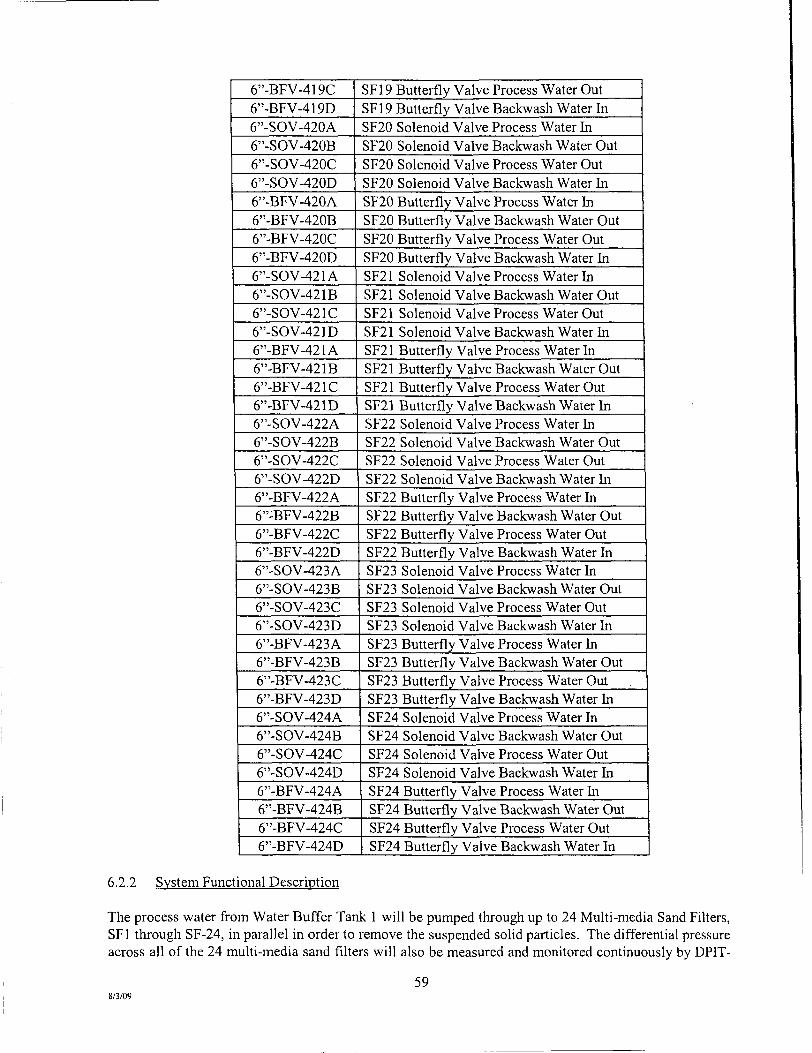
6"-BFV-419C 6"-BFV-419D 6"-SOV-420A 6"-SOV-420B 6"-SOV-420C 6"-SOV-420D 6"-BFV-420A 6"-BFV-420B 6"-BFV-420C 6"-BFV-420D 6"-SOV-421A 6"-SOV-421B 6"-SOV-421C 6"-SOV-421D 6"-BFV-421A 6"-BFV-421B 6"-BFV-421C 6"-BFV-421D 6"-SOV-422A 6"-SOV-422B 6"-SOV-422C 6"-SOV-422D 6"-BFV-422A 6 " : B F V - 4 2 2 B
6"-BFV-422C 6"-BFV-422D 6".SOV-423A 6"-SOV-423B 6"-SOV-423C 6"-SOV-423D 6"-BFV-423A 6"-BFV-423B 6"-BFV-423C 6"-BFV-423D 6".SOV-424A 6"-SOV-424B 6"-SOV-424C 6"-SOV-424D 6"-BFV-424A 6"-BFV-424B 6"-BFV-424C 6"-BFV-424D
SFl 9 Butterfly Valve Process Water Out SFl9 Butterfly Valve Backwash Water hi SF20 Solenoid Valve Process Water hi SF20 Solenoid Valve Backwash Water Out SF20 Solenoid Valve Process Water Out SF20 Solenoid Valve Backwash Water hi SF20 Butterfly Valve Process Water hi SF20 Butterfly Valve Backwash Water Out SF20 Butterfly Valve Process Water Out SF20 Butterfly Valve Backwash Water In SF21 Solenoid Valve Process Water hi SF21 Solenoid Valve Backwash Water Out SF21 Solenoid Valve Process Water Out SF21 Solenoid Valve Backwash Water hi SF21 Butterfly Valve Process Water hi SF21 Butterfly Valve Backwash Water Out SF21 Butterfly Valve Process Water Out SF21 Butterfly Valve Backwash Water hi SF22 Solenoid Valve Process Water In SF22 Solenoid Valve Backwash Water Out SF22 Solenoid Valve Process Water Out SF22 Solenoid Valve Backwash Water In SF22 Butterfly Valve Process Water In SF22 Butterfly Valve Backwash Water Out SF22 Butterfly Valve Process Water Out SF22 Butterfly Valve Backwash Water hi SF23 Solenoid Valve Process Water hi SF23 Solenoid Valve Backwash Water Out SF23 Solenoid Valve Process Water Out SF23 Solenoid Valve Backwash Water hi SF23 Butterfly Valve Process Water hi SF23 Butterfly Valve Backwash Water Out SF23 Butterfly Valve Process Water Out SF23 Butterfly Valve Backwash Water hi SF24 Solenoid Valve Process Water In SF24 Solenoid Valve Backwash Water Out SF24 Solenoid Valve Process Water Out SF24 Solenoid Valve Backwash Water hi SF24 Butterfly Valve Process Water In SF24 Butterfly Valve Backwash Water Out SF24 Butterfly Valve Process Water Out SF24 Butterfly Valve Backwash Water hi
6.2.2 Svstem Functional Description
The process water from Water Buffer Tank 1 will be pumped through up to 24 Multi-media Sand Filters, SFl through SF-24, in parallel in order to remove the suspended solid particles. The differential pressure across all of the 24 multi-media sand filters will also be measured and monitored continuously by DPIT-
59 8/3/09

450. Each muhi-media sand fiher will be equipped with four solenoid operated valves, two normally open for process water in and out and two normally closed for backwash water in and out. The effluent process water from the Multi-media Sand Filters will be sent to the Bag Filters. During the backwash cycle, treated water from the Effluent Tank will be used to backwash each multi-media sand filter one by one, remove any accumulated fines, and send the fines to the Overflow Tank in the SDDP. Each multimedia sand filter will also be equipped with a flow meter that will measure the flow rate of the water leaving the multi-media sand filter; Each multi-media sand filter will also be equipped with inlet and outlet pressure gauges.
The backwash cycle can be initiated in manual or automatic mode based on any one of three conditions: based on a timer; based on a high differential pressure reading; or, based on a low flow measurement. One of the two Backwash Pumps P-5 A or P-5B will pump treated water from the Effluent Tank to the 24 multi-media sand filters during a backwash cycle. The second pump will serve as a spare. During a backwash cycle, the two normally open process water solenoid operated valves will be closed and the two normally closed backwash water solenoid operated valves will be opened. For the purposes of backwashing, the 24 multi-media sand filters will be divided into six groups of four filters each. During an automatic backwash cycle, the four multi-media sand filters in a group will be backwashed individually in a sequential marmer. In manual mode, the Operator will have to start and stop the backwash cycle for each multi-media sand filter until backwashing has been completed for each multimedia sand filter. It is anticipated that each multi-media sand filter will be backwashed once daily.
The duration for backwashing any given multi-media sand filter will be based on the total suspended solids concentration in the backwash outlet stream going to the Overflow Tank in the SDDP. Based on operational experience to date, satisfactory backwash of each multi-media sand filter can be accomplished in approximately 10 minutes at a flow rate of 600 gpm once per day. A sample should be drawn from the sample tap in the backwash piping and examined visually to confirm that the backwash operation is complete. Over time the duration needed for backwash of these units may be extended and/or the flow rate increased, based on visual examination of the backwash samples for clarity.
Each of the four solenoid operated valves on each multi-media sand filter will receive open or close signals from the PLC and each valve will send two limit switch signals to the PLC for open-close verification and corresponding display on the HMl screen. Alarms for a high differential pressure across all the multi-media sand filters or a low flow of effluent process water from any individual multi-media sand filter will also be displayed on the HMl screen.
Instmmentation and controls associated with the Multi-media Sand Filtration Process Loop are summarized in the following table:
^ Set'point' mmmm^ jMnm^ ^ m^mm Differential Pressure hidicator Transmitter DPIT-450
10 psi Indicates and transmits differential pressure across all of the sand filters
Differential Pressure Alarm DPAH-450
20 psi Alarms high differential pressure across all of the sand filters Indicates pressure in SFl process water inlet Pressure Indicator PI-401A Indicates pressure in SFl process water outlet Pressure Indicator PI-401B
Flow Element FE-401 Measures flow rate of process water from SFl Flow Indicator Transmitter FIT-401
350 gpm Indicates and transmits flow rate of process water from SFl
Flow Alarm FAL-401 200 gpm Alarms low flow rate of process water from SFl Pressure Indicator PI-402A Indicates pressure in SF2 process water inlet
60 8/3/09

Pressure Indicator PI-402B Flow Element FE-402 Flow Indicator Transmitter FIT-402 Flow Alarm FAL-402 Pressure Indicator P1-403A Pressure Indicator PI-403B Flow Element FE-403 Flow Indicator Transmitter FIT-403 Flow Alarm FAL-403 Pressure Indicator P1-404A Pressure hidicator P1-404B Flow Element FE-404 Flow Indicator Transmitter FIT-404 Flow Alarm FAL-404 Pressure hidicator PI-405A Pressure hidicator P1-405B Flow Element FE-405 Flow Indicator Transmitter FIT-405 Flow Alami FAL-405 Pressure Indicator PI-406A Pressure Indicator PI-406B Flow Element FE-406 Flow Indicator Transmitter FIT-406 Flow Alarm FAL-406 Pressure hidicator PI-407A Pressure Indicator PI-407B Flow Element FE-407 Flow Indicator Transmitter FIT-407 Flow Alarm FAL-407 Pressure hidicator PI-408A Pressure hidicator PI-408B Flow Element FE-408 Flow Indicator Transmitter FIT-408 Flow Alarm FAL-408 Pressure hidicator P1-409A Pressure hidicator PI-409B Flow Element FE-409 Flow Indicator Transmitter FIT-409 Flow Alarm FAL-409 Pressure Indicator PI-410A
350 gpm
200 gpm
350 gpm
200 gpm
350 gpm
200 gpm
350 gpm
200 gpm
350 gpm
200 gpm
350 gpm
200 gpm
350 gpm
200 gpm
350 gpm
200 gpm
Indicates pressure in SF2 process water outlet Measures flow rate of process water from SF2 Indicates and transmits flow rate of process water from SF2 Alarms low flow rate of process water from SF2 Indicates pressure in SF3 process water inlet Indicates pressure in SF3 process water outlet Measures flow rate of process water from SF3 Indicates and transmits flow rate of process water from SF3 Alarms low flow rate of process water from SF3 Indicates pressure in SF4 process water inlet Indicates pressure in SF4 process water outlet Measures flow rate of process water from SF4 Indicates and transmits flow rate of process water from SF4 Alarms low flow rate of process water from SF4 Indicates pressure in SF5 process water inlet Indicates pressure in SF5 process water outlet Measures flow rate of process water from SF5 Indicates and transmits flow rate of process water from SF5 Alarms low flow rate of process water from SF5 Indicates pressure in SF6 process water inlet Indicates pressure in SF6 process water outlet Measures flow rate of process water from SF6 Indicates and transmits flow rate of process water from SF6 Alarms low flow rate of process water from SF6 Indicates pressure in SF7 process water inlet Indicates pressure in SF7 process water outlet Measures flow rate of process water from SF7 Indicates and transmits flow rate of process water from SF7 Alarms low flow rate of process water from SF7 Indicates pressure in SF8 process water inlet Indicates pressure in SF8 process water outlet Measures flow rate of process water from SF8 Indicates and transmits flow rate of process water from SF8 Alarms low flow rate of process water from SF8 Indicates pressure in SF9 process water inlet Indicates pressure in SF9 process water outlet Measures flow rate of process water from SF9 Indicates and transmits flow rate of process water from SF9 Alarms low flow rate of process water from SF9 Indicates pressure in SFIO process water inlet
8/3/09 61

Pressure hidicator PI-410B Flow Element FE-410 Flow Indicator Transmitter FIT-410 Flow Alarm FAL-410 Pressure Indicator Pl-411A Pressure hidicator Pl-41 IB Flow Element FE-411 Flow Indicator Transmitter FIT-411 Flow Alarm FAL-411 Pressure Indicator Pl-412A Pressure hidicator Pl-412B Flow Element FE-412 Flow Indicator Transmitter FIT-412 Flow Alarm FAL-412 Pressure Indicator Pl-413 A Pressure Indicator Pl-413B Flow Element FE-413 Flow Indicator Transmitter FIT-413 Flow Alarm FAL-413 Pressure Indicator Pl-414A Pressure Indicator Pl-414B Flow Element FE-414 Flow Indicator Transmitter FIT-414 Flow Alarm FAL-414 Pressure Indicator Pl-415A Pressure Indicator Pl-415B Flow Element FE-415 Flow Indicator Transmitter FIT-415 Flow Alarm FAL-415 Pressure Indicator PI-416A Pressure Indicator Pl-416B Flow Element FE-416 Flow Indicator Transmitter FIT-416 Flow Alarm FAL-416 Pressure Indicator Pl-417A Pressure Indicator PI-417B Flow Element FE-417 Flow Indicator Transmitter FIT-417 Flow Alami FAL-417 Pressure Indicator Pl-418 A
350 gpm
200 gpm
350 gpm
200 gpm
350 gpm
200 gpm
350 gpm
200 gpm
350 gpm
200 gpm
350 gpm
200 gpm
350 gpm
200 gpm
350 gpm
200 gpm
Indicates pressure in SFIO process water outlet Measures flow rate of process water from SFIO Indicates and transmits flow rate of process water from SFIO Alarms low flow rate of process water from SFIO Indicates pressure in SFl 1 process water inlet Indicates pressure in SFl 1 process water outlet Measures flow rate of process water from SFl 1 Indicates and transmits flow rate of process water from SFll Alarms low flow rate of process water from SFl 1 Indicates pressure in SFl2 process water inlet Indicates pressure in SFl2 process water outlet Measures flow rate of process water from SFl 2 Indicates and transmits flow rate of process water from SFl2 Alarms low flow rate of process water from SFl 2 Indicates pressure in SFl3 process water inlet Indicates pressure in SFl3 process water outlet Measures flow rate of process water from SFl 3 Indicates and transmits flow rate of process water from SFl 3 Alarms low flow rate of process water from SFl 3 Indicates pressure in SFl4 process water inlet Indicates pressure in SFl4 process water outlet Measures flow rate of process water from SFl 4 Indicates and transmits flow rate of process water from SF14 Alarms low flow rate of process water from SFl 4 Indicates pressure in SFl 5 process water inlet Indicates pressure in SFl5 process water outlet Measures flow rate of process water from SFl 5 Indicates and transmits flow rate of process water from SFl 5 Alarms low flow rate of process water from SFl 5 Indicates pressure in SFl 6 process water inlet Indicates pressure in SFl6 process water outlet Measures flow rate of process water from SFl 6 Indicates and transmits flow rate of process water from SFl6 Alarms low flow rate of process water from SFl 6 Indicates pressure in SFl 7 process water inlet Indicates pressure in SFl7 process water outlet Measures flow rate of process water from SFl 7 Indicates and transmits flow rate of process water from SFl7 Alarms low flow rate of process water from SFl 7 Indicates pressure in SFl 8 process water mlet
8/3/09 62

Pressure hidicator Pl-418B Flow Element FE-418 Flow Indicator Transmitter FIT-418 Flow Alarm FAL-418 Pressure Indicator Pl-419A Pressure hidicator PI-419B Flow Element FE-419 Flow Indicator Transmitter FIT-419 Flow Alarm FAL-419 Pressure Indicator PI-420A Pressure hidicator PI-420B Flow Element FE-420 Flow Indicator Transmitter FIT-420 Flow Alann FAL-420 Pressure Indicator Pl-421 A Pressure hidicator PI-421B Flow Element FE-421 Flow Indicator Transmitter FIT-421 Flow Alarm FAL-421 Pressure hidicator PI-422A Pressure hidicator PI-422B Flow Element FE-422 Flow Indicator Transmitter FIT-422 Flow Alarm FAL-422 Pressure Indicator PI-423A Pressure hidicator PI-423B Flow Element FE-423 Flow Indicator Transmitter FIT-423 Flow Alarm FAL-423 Pressure hidicator P1-424A Pressure hidicator PI-424B Flow Element FE-424 Flow Indicator Transmitter FIT-424 Flow Alarm FAL-424
350 gpm
200 gpm
350 gpm
200 gpm
350 gpm
200 gpm
350 gpm
200 gpm
350 gpm
200 gpm
350 gpm
200 gpm
350 gpm
200 gpm
Indicates pressure in SFl 8 process water outlet Measures flow rate of process water from SFl 8 Indicates and transmits flow rate of process water from SFl8 Alarms low flow rate of process water from SFl 8 Indicates pressure in SFl9 process water inlet Indicates pressure in SFl 9 process water outlet Measures flow rate of process water from SFl 9 Indicates and transmits flow rate of process water from SFl9 Alarms low flow rate of process water from SFl 9 Indicates pressure in SF20 process water inlet Indicates pressure in SF20 process water outlet Measures flow rate of process water from SF20 Indicates and transmits flow rate of process water from SF20 Alarms low flow rate of process water from SF20 Indicates pressure in SF21 process water inlet Indicates pressure in SF21 process water outlet Measures flow rate of process water from SF21 Indicates and transmits flow rate of process water fromSF21 Alarms low flow rate of process water from SF21 Indicates pressure in SF22 process water inlet i Indicates pressure in SF22 process water outlet Measures flow rate of process water from SF22 Indicates and transmits flow rate of process water from SF22 Alarms low flow rate of process water from SF22 Indicates pressure in SF23 process water inlet Indicates pressure in SF23 process water outlet Measures flow rate of process water from SF23 Indicates and transmits flow rate of process water from SF23 Alarms low flow rate of process water from SF23 Indicates pressure in SF24 process water inlet Indicates pressure in SF24 process water outlet Measures flow rate of process water from SF24 Indicates and transmits flow rate of process water from SF24 Alarms low flow rate of process water from SF24
6.2.3 Interlock Summary
There are no interlocks for this process loop.
8/3/09 63

6.3 Process Loop #3 - Bag Filtration
This process loop corresponds to P&ID P-l06. The major equipment for this process loop is listed in Section 6.3.1, the instmmentation and controls and the functional description are included in Section 6.3.2 and the process interlocks are listed in Section 6.3.3.
6.3.1 Major Equipment
5iJsag*Nuni|bMErri|i BFl through
BF6 1"-BV-607A
1"-BV-607B
y2"-BV-601A
'/2"-BV-601B
72"-BV-602A
y2"-BV-602B
'/2"-BV-603A
'/2"-BV-603B
'/2"-BV-604A
'/2"-BV-604B
'/2"-BV-605A
'/2"-BV-605B
'/2"-BV-606A
'/2"-BV-606B
8"-BFV-BFl-l 8"-BFV-BFl-2 8"-BFV-BF2-l 8"-BFV-BF2-2 8"-BFV-BF3-l 8"-BFV-BF3-2 8"-BFV-BF4-l 8"-BFV-BF4-2
lsAi#;ifegii'tls§I)esc^ Bag Filters 1 through 6
Isolation Valve Bag Filter Differential Pressure Indicator Transmitter Isolation Valve Bag Filter Differential Pressure Indicator Transmitter Isolation Valve BFl Pressure Gauge Process Water hi Isolation Valve BFl Pressure Gauge Process Water Out Isolation Valve BF2 Pressure Gauge Process Water In Isolation Valve BF2 Pressure Gauge Process Water Out Isolation Valve BF3 Pressure Gauge Process Water hi Isolation Valve BF3 Pressure Gauge Process Water Out Isolation Valve BF4 Pressure Gauge Process Water In Isolation Valve BF4 Pressure Gauge Process Water Out Isolation Valve BF5 Pressure Gauge Process Water In Isolation Valve BF5 Pressure Gauge Process Water Out Isolation Valve BF6 Pressure Gauge Process Water In Isolation Valve BF6 Pressure Gauge Process Water Out Butterfly Valve BFl Process Water hi Butterfly Valve BFl Process Water Out Butterfly Valve BF2 Process Water hi Butterfly Valve BF2 Process Water Out Butterfly Valve BF3 Process Water hi Butterfly Valve BF3 Process Water Out Butterfly Valve BF4 Process Water hi Butterfly Valve BF4 Process Water Out
8/3/09 64

8"-BFV-BF5-l 8"-BFV-BF5-2 8"-BFV-BF6-l 8"-BFV-BF6-2 18"-BFV-BP-1
Butterfly Valve BF5 Process Water hi Butterfly Valve BF5 Process Water Out Butterfly Valve BF6 Process Water In Butterfly Valve BF6 Process Water Out Bypass Valve directs Bag FiUer Effluent to Cartridge Filter Influent when closed
6.3.2 System Functional Description
Process water from the Multi-media Sand Filters will be pumped through up to six Muhi-Bag Filter Vessels, BFl through BF6 in parallel to remove fine suspended solid particles. The differential pressure across all of the 6 multi-bag filter vessels will also be measured and monitored continuously by DPIT-620. Each multi-bag filter vessel will be equipped with manually operated butterfly valves on the inlet and outlet. Each multi-bag filter vessel will also be equipped with inlet and outlet pressure gauges. It is anticipated that under normal operation, at least one multi-bag filter vessel will be offline for replacement of the bags. An alarm for a high differential pressure across all the multi-bag filter vessels will also be displayed on the HMl screen. The Operator will sequentially take one of the operating multi-bag filter vessels offline and bring the multi-bag filter vessel with the newly replaced bags online till the high differential pressure alarm is cleared.
Instmmentation and controls associated with the Bag Filtration Process Loop are summarized in the following table:
^g^Setpointg ; j g g M ^ i i i i i i a g i i i l E M t ^ ^ Differential Pressure Indicator Transmitter DPIT-620
10 psi Indicates and transmits differential pressure across all of the bag filters
Differential Pressure Alarm DPAH-620
20 psi Alarms high differential pressure across all of the bag filters
Pressure Indicator PI-611A Indicates pressure in BFl process water inlet Pressure Indicator Pl-61 IB Indicates pressure in BFl process water outlet Pressure Indicator PI-612A Indicates pressure in BF2 process water inlet Pressure Indicator PI-612B Indicates pressure in BF2 process water outlet Pressure Indicator Pl-613A Indicates pressure in BF3 process water inlet Pressure Indicator PI-613B Indicates pressure in BF3 process water outlet Pressure Indicator PI-614A Indicates pressure in BF4 process water inlet Pressure Indicator Pl-614B Indicates pressure in BF4 process water outlet Pressure Indicator PI-615 A Indicates pressure in BF5 process water mlet Pressure Indicator PI-615B Indicates pressure in BF5 process water outlet Pressure Indicator PI-616 A Indicates pressure in BF6 process water inlet Pressure hidicator PI-616B Indicates pressure in BF6 process water outlet
6.3.3 Interlock Summary
There are no interlocks for this process loop
6.4 Process Loop #4 - Granular Activated Carbon Adsorption
65 8/3/09

This process loop corresponds to P&ID P-106. The major equipment for this process loop is listed in Section 6.4.1, the instmmentation and controls and the functional description are included in Section 6.4.2 and the process interlocks are listed in Section 6.4.3.
6.4.1 Major Equipment
i55i£glag!:Numb(Eisgvife: > GFl through
GFl 8 2"-BV-680
2"-AVV-680
8"-BFV-GFlA 8"-BFV-GFlB 8"-BFV-GFlC
8"-BFV-GFlD
8"-BFV-GFlE 8"-BFV-GF2A 8"-BFV-GF2B 8"-BFV-GF2C
8"-BFV-GF2D
8"-BFV-GF2E 8"-BFV-GF3A 8"-BFV-GF3B 8"-BFV-GF3C
8"-BFV-GF3D
8"-BFV-GF3E 8"-BFV-GF4A 8"-BFV-GF4B 8"-BFV-GF4C
8"-BFV-GF4D
8"-BFV-GF4E 8"-BFV-GF5A 8"-BFV-GF5B 8"-BFV-GF5C
8"-BFV-GF5D
8"-BFV-GF5E 8"-BFV-GF6A 8"-BFV-GF6B
Jl<;^!^.•;^.l^[,•^•^^i.?'-t.^'fnr;4^.'ti:f.t•M^^
Granulated Activated Carbon Adsorbers 1 through 18 Ball Valve Air Vacuum Valve at High Point of Piping Bridge Re-activated Carbon Inlet Valve GFl Spent Carbon Outlet Valve GFl Isolation Valve Differential Pressure Indicator Transmitter GFl Isolation Valve Differential Pressure Indicator Transmitter GFl Isolation Valve GFl Pressure Gauge Re-activated Carbon hilet Valve GF2 Spent Carbon Ouflet Valve GF2 Isolation Valve Differential Pressure Indicator Transmitter GF2 Isolation Valve Differential Pressure Indicator Transmitter GF2 Isolation Valve GF2 Pressure Gauge Re-activated Carbon Inlet Valve GF3 Spent Carbon Outlet Valve GF3 Isolation Valve Differential Pressure Indicator Transmitter GF3 Isolation Valve Differential Pressure Indicator Transmitter GF3 Isolation Valve GF3 Pressure Gauge Re-activated Carbon hilet Valve GF4 Spent Carbon Outlet Valve GF4 Isolation Valve Differential Pressure Indicator Transmitter GF4 Isolation Valve Differential Pressure Indicator Transmitter GF4 Isolation Valve GF4 Pressure Gauge Re-activated Carbon hilet Valve GF5 Spent Carbon Ouflet Valve GF5 Isolation Valve Differential Pressure Indicator Transmitter GF5 Isolation Valve Differential Pressure Indicator Transmitter GF5 Isolation Valve GF5 Pressure Gauge Re-activated Carbon Inlet Valve GF6
1 Spent Carbon Outlet Valve GF6
66 8/3/09

8"-BFV-GF6C
8"-BFV-GF6D
8"-BFV-GF6E 8"-BFV-GF7A 8"-BFV-GF7B 8"-BFV-GF7C
8"-BFV-GF7D
8"-BFV-GF7E 8"-BFV-GF8A 8"-BFV-GF8B 8"-BFV-GF8C
8"-BFV-GF8D
8"-BFV-GF8E 8"-BFV-GF9A 8"-BFV-GF9B 8"-BFV-GF9C
8"-BFV-GF9D
8"-BFV-GF9E 8"-BFV-GF10A 8"-BFV-GF10B 8"-BFV-GF10C
8"-BFV-GF10D
8"-BFV-GF10E 8"-BFV-GFllA 8"-BFV-GFllB 8"-BFV-GFllC
8"-BFV-GFllD
8"-BFV-GFllE 8"-BFV-GF12A 8"-BFV-GF12B 8"-BFV-GF12C
8"-BFV-GF12D
8"-BFV-GF12E 8"-BFV-GF13A 8"-BFV-GF13B
Isolation Valve Differential Pressure Indicator Transmitter GF6 Isolation Valve Differential Pressure Indicator Transmitter GF6 Isolation Valve GF6 Pressure Gauge Re-activated Carbon hilet Valve GF7 Spent Carbon Outlet Valve GF7 Isolation Valve Differential Pressure Indicator Transmitter GF7 Isolation Valve Differential Pressure Indicator Transmitter GF7 Isolation Valve GF7 Pressure Gauge Re-activated Carbon hilet Valve GF8 Spent Carbon Outlet Valve GF8 Isolation Valve Differential Pressure Indicator Transmitter GF8 Isolation Valve Differential Pressure Indicator Transmitter GF8 Isolation Valve GF8 Pressure Gauge Re-activated Carbon hilet Valve GF9 Spent Carbon Outlet Valve GF9 Isolation Valve Differential Pressure Indicator Transmitter GF9 Isolation Valve Differential Pressure Indicator Transmitter GF Isolation Valve GF9 Pressure Gauge Re-activated Carbon hilet Valve GFIO Spent Carbon Outlet Valve GFIO Isolation Valve Differential Pressure Indicator Transmitter GFIO Isolation Valve Differential Pressure Indicator Transmitter GFIO Isolation Valve GFIO Pressure Gauge Re-activated Carbon Inlet Valve GFll Spent Carbon Outlet Valve GFl 1 Isolation Valve Differential Pressure Indicator Transmitter GFl 1 Isolation Valve Differential Pressure Indicator Transmitter GFl 1 Isolation Valve GFl 1 Pressure Gauge Re-activated Carbon hilet Valve GFl 2 Spent Carbon Outlet Valve GFl2 Isolation Valve Differential Pressure hidicator Transmitter GFl2 Isolation Valve Differential Pressure Indicator Transmitter GFl 2 Isolation Valve GFl2 Pressure Gauge Re-activated Carbon hilet Valve GFl 3 Spent Carbon Outlet Valve GFl3
67 8/3/09

8"-BFV-GF13C
8"-BFV-GF13D
8"-BFV-GF13E 8"-BFV-GF14A 8"-BFV-GF14B 8"-BFV-GF14C
8"-BFV-GF14D
8"-BFV-GF14E 8"-BFV-GF15A 8"-BFV-GF15B 8"-BFV-GF15C
8"-BFV-GF15D
8"-BFV-GF15E 8"-BFV-GF16A 8"-BFV-GF16B 8"-BFV-GF16C
8"-BFV-GF16D
8"-BFV-GF16E 8"-BFV-GF17A 8"-BFV-GF17B 8"-BFV-GF17C
8"-BFV-GF17D
8"-BFV-GF17E 8"-BFV-GF18A 8"-BFV-GF18B 8"-BFV-GF18C
8"-BFV-GF18D
8"-BFV-GF18E 8"-BFV-GFl-2 8"-BFV-GFl-4 8"-BFV-GFl-6 8"-BFV-GFl-8 8"-BFV-GFl-10 8"-BFV-GF2-l 8"-BFV-GF2-3 8"-BFV-GF2-5
Isolation Valve Differential Pressure Indicator Transmitter GFl 3 Isolation Valve Differential Pressure Indicator Transmitter GFl3 Isolation Valve GFl 3 Pressure Gauge Re-activated Carbon hilet Valve GFl4 Spent Carbon Outlet Valve GFl4 Isolation Valve Differential Pressure Indicator Transmitter GFl4 Isolation Valve Differential Pressure Indicator Transmitter GFl4 Isolafion Valve GFl4 Pressure Gauge Re-activated Carbon Inlet Valve GFl5 Spent Carbon Outlet Valve GFl5 Isolation Valve Differential Pressure Indicator Transmitter GFl 5 Isolation Valve Differential Pressure Indicator Transmitter GFl 5 Isolation Valve GFl5 Pressure Gauge Re-activated Carbon Inlet Valve GFl6 Spent Carbon Outlet Valve GFl6 Isolation Valve Differential Pressure Indicator Transmitter GFl 6 Isolation Valve Differential Pressure hidicator Transmitter GFl6 Isolation Valve GFl6 Pressure Gauge Re-activated Carbon Inlet Valve GFl 7 Spent Carbon Outlet Valve GFl 7 Isolation Valve Differential Pressure Indicator Transmitter GFl7 Isolation Valve Differential Pressure Indicator Transmitter GFl7 Isolation Valve GFl 7 Pressure Gauge Re-activated Carbon hilet Valve GFl 8 Spent Carbon Outlet Valve GFl 8 Isolation Valve Differential Pressure Indicator Transmitter GFl 8 Isolation Valve Differential Pressure Indicator Transmitter GFl8 Isolation Valve GFl8 Pressure Gauge hifluent Valve GFl Effluent Valve GFl Vent Valve GFl Backwash hilet Valve GFl Cross-over Valve GFl hifluent Valve GF2 Effluent Valve GF2 Vent Valve GF2
8"-BFV-GF2-7 Backwash hilet Valve GF2 68
8/3/09

8"-BFV-GF2-9 8"-BFV-GF3-2 8"-BFV-GF3-4 8"-BFV-GF3-6 8"-BFV-GF3-8 8"-BFV-GF3-10 8"-BFV-GF4-l 8"-BFV-GF4-3 8"-BFV-GF4-5 8"-BFV-GF4-7 8"-BFV-GF4-9 8"-BFV-GF5-2 8"-BFV-GF5-4 8"-BFV-GF5-6 8"-BFV-GF5-8 8"-BFV-GF5-10 8"-BFV-GF6-l 8"-BFV-GF6-3 8"-BFV-GF6-5 8"-BFV-GF6-7 8"-BFV-GF6-9 8"-BFV-GF7-2 8"-BFV-GF7-4 8"-BFV-GF7-6 8"-BFV-GF7-8 8"-BFV-GF7-10 8"-BFV-GF8-l 8"-BFV-GF8-3 8"-BFV-GF8-5 8"-BFV-GF8-7 8"-BFV-GF8-9 8"-BFV-GF9-2 8"-BFV-GF9-4 8"-BFV-GF9-6 8"-BFV-GF9-8 8"-BFV-GF9-10 8"-BFV-GF10-l 8"-BFV-GF10-3 8"-BFV-GF10-5 8"-BFV-GF10-7 8"-BFV-GF10-9 8"-BFV-GFll-2 8"-BFV-GFll-4 8"-BFV-GFll-6 8"-BFV-GFll-8
8"-BFV-GFll-10 8"-BFV-GF12-l 8"-BFV-GF12-3
Cross-over Valve GF2 hifluent Valve GF3 Effluent Valve GF3 Vent Valve GF3 Backwash Inlet Valve GF3 Cross-over Valve GF3 hifluent Valve GF4 Effluent Valve GF4 Vent Valve GF4 Backwash Inlet Valve GF4 Cross-over Valve GF4 hifluent Valve GF5 Effluent Valve GF5 Vent Valve GF5 Backwash Inlet Valve GF5 Cross-over Valve GF5 hifluent Valve GF6 Effluent Valve GF6 Vent Valve GF6 Backwash hilet Valve GF6 Cross-over Valve GF6 hifluent Valve GF7 Effluent Valve GF7 Vent Valve GF7 Backwash hilet Valve GF7 Cross-over Valve GF7 hifluent Valve GF8 Effluent Valve GF8 Vent Valve GF8 Backwash hilet Valve GF8 Cross-over Valve GF8 hifluent Valve GF9 Effluent Valve GF9 Vent Valve GF9 Backwash hilet Valve GF9 Cross-over Valve GF9 hifluent Valve GFIO Effluent Valve GFIO Vent Valve GFIO Backwash hilet Valve GFIO Cross-over Valve GFIO hifluent Valve GFll Effluent Valve GFl 1 Vent Valve GFll Backwash hilet Valve GFl 1 Cross-over Valve GFl 1 hifluent Valve GFl2 Effluent Valve GFl2
8/3/09 69
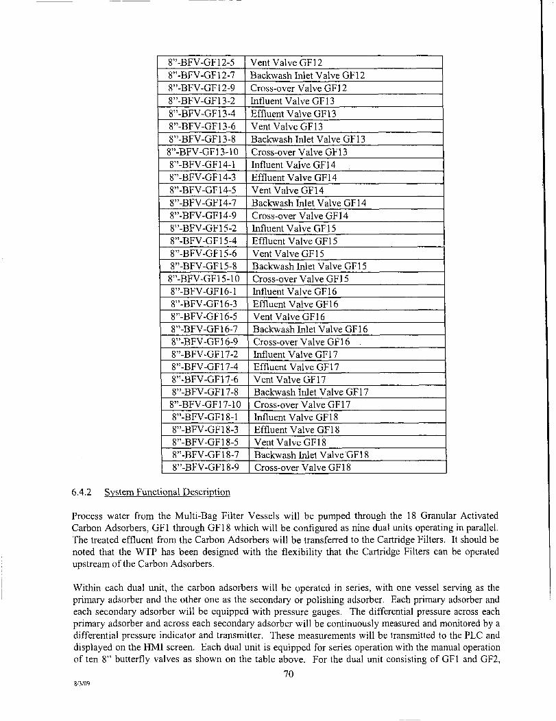
8"-BFV-GF12-5 8"-BFV-GF12-7 8"-BFV-GF12-9 8"-BFV-GF13-2 8"-BFV-GF13-4 8"-BFV-GF13-6 8"-BFV-GF13-8 8"-BFV-GF13-10 8"-BFV-GF14-l 8"-BFV-GF14-3 8"-BFV-GF14-5 8"-BFV-GF14-7 8"-BFV-GF14-9 8"-BFV-GF15-2 8"-BFV-GF15-4 8"-BFV-GF15-6 8"-BFV-GF15-8 8"-BFV-GF15-10 8"-BFV-GF16-l 8"-BFV-GF16-3 8"-BFV-GF16-5 8"-BFV-GF16-7 8"-BFV-GF16-9 8"-BFV-GF17-2 8"-BFV-GF17-4 8"-BFV-GF17-6 8"-BFV-GF17-8
8"-BFV-GF 17-10 8"-BFV-GF18-l 8"-BFV-GF18-3 8"-BFV-GF18-5 8"-BFV-GF18-7 8"-BFV-GF18-9
Vent Valve GFl2 Backwash Inlet Valve GFl2 Cross-over Valve GFl2 hifluent Valve GFl 3 Effluent Valve GFl3 Vent Valve GFl3 Backwash Inlet Valve GFl3 Cross-over Valve GFl 3 hifluent Valve GFl4 Effluent Valve GFl4 Vent Valve GF14 Backwash hilet Valve GFl4 Cross-over Valve GF14 hifluent Valve GFl 5 Effluent Valve GFl 5 Vent Valve GFl 5 Backwash Inlet Valve GFl5 Cross-over Valve GFl 5 hifluent Valve GFl6 Effluent Valve GFl6 Vent Valve GFl 6 Backwash Inlet Valve GFl 6 Cross-over Valve GF 16 hifluent Valve GFl7 Effluent Valve GFl 7 Vent Valve GF17 Backwash Inlet Valve GFl 7 Cross-over Valve GFl7 hifluent Valve GFl 8 Effluent Valve GFl 8 Vent Valve GFl 8 Backwash hilet Valve GFl 8 Cross-over Valve GFl 8
6.4.2 System Functional Description
Process water from the Multi-Bag Filter Vessels will be pumped through the 18 Granular Activated Carbon Adsorbers, GFl through GFl 8 which will be configured as nine dual units operating in parallel. The treated effluent from the Carbon Adsorbers will be transferred to the Cartridge Filters. It should be noted that the WTP has been designed with the flexibility that the Cartridge Filters can be operated upstream of the Carbon Adsorbers.
Within each dual unit, the carbon adsorbers will be operated in series, with one vessel serving as the primary adsorber and the other one as the secondary or polishing adsorber. Each primary adsorber and each secondary adsorber will be equipped with pressure gauges. The differential pressure across each primary adsorber and across each secondary adsorber will be continuously measured and monitored by a differential pressure indicator and transmitter. These measurements will be transmitted to the PLC and displayed on the HMl screen. Each dual unit is equipped for series operation with the manual operation of ten 8" butterfly valves as shown on the table above. For the dual unit consisting of GFl and GF2,
70 8/3/09
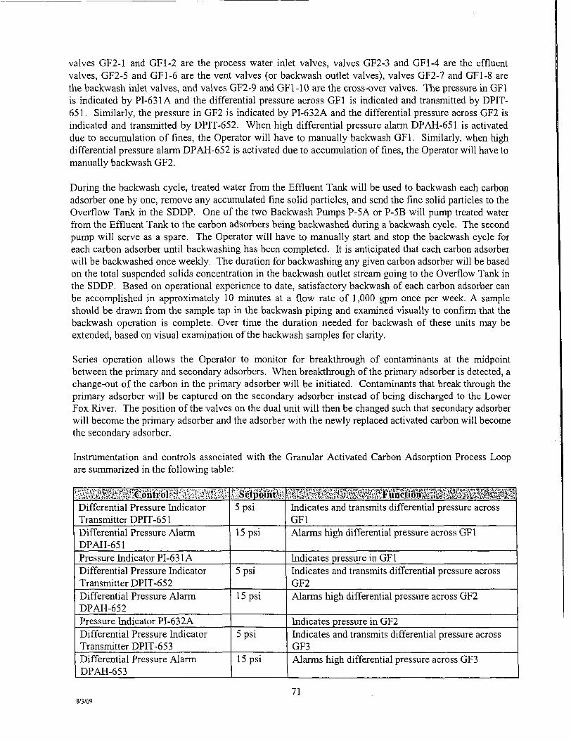
valves GF2-1 and GFl-2 are the process water inlet valves, valves GF2-3 and GFl-4 are the effluent valves, GF2-5 and GFl-6 are the vent valves (or backwash outlet valves), valves GF2-7 and GFl-8 are the backwash inlet valves, and valves GF2-9 and GFl-10 are the cross-over valves. The pressure in GFl is indicated by P1-631A and the differential pressure across GFl is indicated and transmitted by DPIT-651. Similarly, the pressure in GF2 is indicated by P1-632A and the differential pressure across GF2 is indicated and transmitted by DPIT-652. When high differential pressure alarm DPAH-651 is activated due to accumulation of fines, the Operator will have to manually backwash GFl. Similarly, when high differential pressure alarm DPAH-652 is activated due to accumulation of fines, the Operator will have to manually backwash GF2.
During the backwash cycle, treated water from the Effluent Tank will be used to backwash each carbon adsorber one by one, remove any accumulated fine solid particles, and send the fine solid particles to the Overflow Tank in the SDDP. One of the two Backwash Pumps P-5A or P-5B will pump treated water from the Effluent Tank to the carbon adsorbers being backwashed during a backwash cycle. The second pump will serve as a spare. The Operator will have to manually start and stop the backwash cycle for each carbon adsorber until backwashing has been completed. It is anticipated that each carbon adsorber will be backwashed once weekly. The duration for backwashing any given carbon adsorber will be based on the total suspended solids concentration in the backwash outlet stream going to the Overflow Tank in the SDDP. Based on operational experience to date, satisfactory backwash of each carbon adsorber can be accomplished in approximately 10 minutes at a flow rate of 1,000 gpm once per week. A sample should be drawn from the sample tap in the backwash piping and examined visually to confirm that the backwash operation is complete. Over time the duration needed for backwash of these units may be extended, based on visual examination of the backwash samples for clarity.
Series operation allows the Operator to monitor for breakthrough of contaminants at the midpoint between the primary and secondary adsorbers. When breakthrough of the primary adsorber is detected, a change-out of the carbon in the primary adsorber will be initiated. Contaminants that break through the primary adsorber will be captured on the secondary adsorber instead of being discharged to the Lower Fox River. The position of the valves on the dual unit will then be changed such that secondary adsorber will become the primary adsorber and the adsorber with the newly replaced activated carbon will become the secondary adsorber.
Instmmentation and controls associated with the Granular Activated Carbon Adsorption Process Loop are summarized in the following table:
: sabMi&K,i|!;fiGpntr;oltiJfc;fe:t ^ Differential Pressure Indicator Transmitter DPIT-651 Differential Pressure Alarm DPAH-651 Pressure Indicator PI-631A Differential Pressure Indicator Transmitter DPIT-652 Differential Pressure Alarm DPAH-652 Pressure Indicator PI-632A Differential Pressure Indicator Transmitter DPlT-65 3 Differential Pressure Alarm DPAH-653
Setpomt 5 psi
15 psi
5 psi
15 psi
5 psi
15 psi
liiiiiiiiiillil^lliSiiiiil^^ Indicates and transmits differential pressure across GFl Alarms high differential pressure across GFl
Indicates pressure in GFl Indicates and transmits differential pressure across GF2 Alarms high differential pressure across GF2
Indicates pressure in GF2 Indicates and transmits differential pressure across GF3 Alarms high differential pressure across GF3
8/3/09 71

Pressure Indicator PI-633A Differential Pressure Indicator Transmitter DPlT-654 Differential Pressure Alarm DPAH-654 Pressure Indicator PI-634A Differential Pressure hidicator Transmitter DPlT-655 Differential Pressure Alarm DPAH-655
Pressure Indicator PI-635A Differential Pressure Indicator Transmitter DPIT-656 Differential Pressure Alarm DPAH-656 Pressure Indicator PI-63 6A Differential Pressure hidicator Transmitter DPIT-657 Differential Pressure Alarm DPAH-657 Pressure Indicator PI-637A Differential Pressure hidicator Transmitter DPrr-65 8 Differential Pressure Alarm DPAH-658 Pressure Indicator PI-63 8 A Differential Pressure Indicator Transmitter DPIT-659 Differential Pressure Alarm DPAH-659 Pressure Indicator PI-639A Differential Pressure hidicator Transmitter DPIT-660 Differential Pressure Alarm DPAH-660 Pressure Indicator PI-640A Differential Pressure Indicator Transmitter DPrr-661 Differential Pressure Alarm DPAH-661 Pressure Indicator PI-641A Differential Pressure Indicator Transmitter DPIT-662 Differenfial Pressure Alarm DPAH-662 Pressure Indicator PI-642A Differential Pressure Indicator Transmitter DPIT-663 Differential Pressure Alarm
5 psi
15 psi
5 psi
15 psi
5 psi
15 psi
5 psi
15 psi
5 psi
15 psi
5 psi
15 psi
5 psi
15 psi
5 psi
15 psi
5 psi
15 psi
5 psi
15 psi
Indicates pressure in GF3 Indicates and transmits differential pressure across GF4 Alarms high differential pressure across GF4
Indicates pressure in GF4 Indicates and transmits differential pressure across GF5 Alarms high differential pressure across GF5
Indicates pressure in GF5 Indicates and transmits differential pressure across GF6 Alarms high differential pressure across GF6
Indicates pressure in GF6 Indicates and transmits differential pressure across GF7 Alamis high differential pressure across GF7
Indicates pressure in GF7 Indicates and transmits differential pressure across GF8 Alarms high differential pressure across GF8
Indicates pressure in GF8 Indicates and transmits differential pressure across GF9 Alarms high differential pressure across GF9
Indicates pressure in GF9 Indicates and transmits differential pressure across GFIO Alarms high differential pressure across GFIO
Indicates pressure in GFIO Indicates and transmits differential pressure across GFll Alarms high differential pressure across GFl 1
Indicates pressure in GFl 1 Indicates and transmits differential pressure across GF12 Alarms high differential pressure across GFl2
Indicates pressure in GFl2 Indicates and transmits differential pressure across GF13 Alanns high differential pressure across GFl3
72 8/3/09
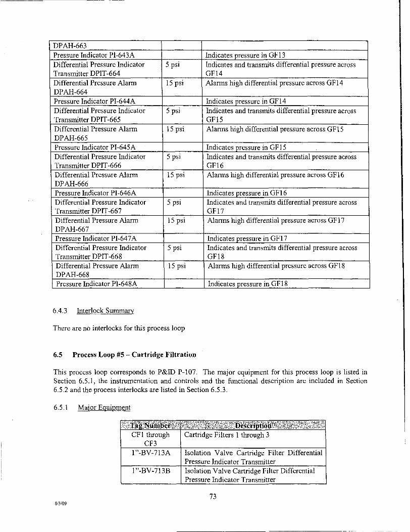
DPAH-663 Pressure Indicator PI-643A Differential Pressure Indicator Transmitter DPlT-664 Differential Pressure Alarm DPAH-664 Pressure Indicator PI-644A Differenfial Pressure Indicator Transmitter DPIT-665 Differential Pressure Alarm DPAH-665 Pressure Indicator P1-645A Differential Pressure Indicator Transmitter DPIT-666 Differential Pressure Alarm DPAH-666 Pressure Indicator PI-646A Differential Pressure Indicator Transmitter DPIT-667 Differential Pressure Alarm DPAH-667 Pressure Indicator PI-647A Differential Pressure Indicator Transmitter DPlT-668 Differential Pressure Alarm DPAH-668 Pressure Indicator PI-648A
5 psi
15 psi
5 psi
15 psi
5 psi
15 psi
5 psi
15 psi
5 psi
15 psi
Indicates pressure in GFl3 Indicates and transmits differential pressure across GF14 Alarms high differential pressure across GFl4
Indicates pressure in GFl4 Indicates and transmits differential pressure across GFl 5 Alarms high differential pressure across GFl5
Indicates pressure in GF 15 Indicates and transmits differential pressure across GFl 6 Alarms high differential pressure across GFl6
Indicates pressure in GFl 6 Indicates and transmits differential pressure across GF17 Alarms high differential pressure across GFl7
Indicates pressure in GFl 7 Indicates and transmits differential pressure across GFl 8 Alarms high differential pressure across GFl 8
Indicates pressure in GFl 8
6.4.3 Interlock Summary
There are no interlocks for this process loop
6.5 Process Loop #5 - Cartridge Filtration
This process loop corresponds to P&DD P-l07. The major equipment for this process loop is listed in Section 6.5.1, the instmmentation and controls and the ftinctional description are mcluded in Section 6.5.2 and the process interlocks are listed in Section 6.5.3.
6.5.1 Major Equipment
CFl through CF3
1"-BV-713A
1"-BV-713B
Cartridge Filters 1 through 3
Isolation Valve Cartridge Filter Differenfial Pressure Indicator Transmitter Isolation Valve Cartridge Filter Differential Pressure Indicator Transmitter
73 8/3/09

1"-BV-710A
1"-BV-710B
1"-BV-711A
1"-BV-711B
1"-BV-712A
1"-BV-712B
16"-BFV-CF1-1 16"-BFV-CFl-2 16"-BFV-CF2-1 16"-BFV-CF2-2 16"-BFV-CF3-1 16"-BFV-CF3-2 18"-BFV-BP-2
18"-BFV-BP-3
18"-BFV-BP-4
18"-BFV-BP-5
18"-BFV-BP-6
Isolation Valve CFl Pressure Gauge Process Water hi Isolation Valve CFl Pressure Gauge Process Water Out Isolation Valve CF2 Pressure Gauge Process Water In Isolation Valve CF2 Pressure Gauge Process Water Out Isolation Valve CF3 Pressure Gauge Process Water hi Isolation Valve CF3 Pressure Gauge Process Water Out Butterfly Valve CFl Process Water hi Butterfly Valve CFl Process Water Out Butterfly Valve CF2 Process Water In Butterfly Valve CF2 Process Water Out Butterfly Valve CF3 Process Water hi Butterfly Valve CF3 Process Water Out Bypass Valve directs Bag Filter Effluent to Cartridge Filter Influent when open Bypass Valve directs Carbon Adsorber Effluent to Cartridge Filter Influent when open Bypass Valve directs Cartridge Filter Effluent to Carbon Adsorber Influent when open Bypass Valve directs Cartridge Filter Effluent to Effluent Tank when open Bypass Valve directs Carbon Adsorber Effluent to Cartridge Filter Influent when closed
6.5.2 Svstem Functional Description
Process water from the Carbon Adsorbers will be pumped through up to three Cartridge Filter Vessels, CFl through CF3 in parallel to remove fine suspended solid particles. The effluent from the Cartridge Filter Vessels will be transferred to the Effluent Tank. It should be noted that the WTP has been designed with the flexibility that the Cartridge Filters can be operated upstream of the Carbon Adsobers.
The differential pressure across all of the 3 cartridge filter vessels will also be measured and monitored continuously by DPIT-713. Each cartridge filter vessel will be equipped with manually operated butterfly valves on the inlet and outlet. Each cartridge filter vessel will also be equipped with inlet and outlet pressure gauges. It is anticipated that under normal operation, at least one cartridge filter vessel will be offline for replacement of the cartridges. An alarm for a high differential pressure across all the cartridge filter vessels will also be displayed on the HMl screen. The Operator will sequentially take one of the operating cartridge filter vessels offline and bring the cartridge filter vessel with the newly replaced cartridges online till the high differential pressure alarm is cleared. The piping and valves have been arranged in a manner that allows the cartridge filters to be operated either upstream or downstream of the Carbon Adsorbers.
74 8/3/09

Instmmentation and controls associated with the Cartridge Filtration Process Loop are summarized in the following table:
wms mmimm^ mm Differential Pressure hidicator Transmitter DPIT-713 Differential Pressure Alarm DPAH-713 Pressure hidicator PI-710A Pressure hidicator P1-710B Pressure Indicator PI-711A Pressure Indicator PI-71 IB Pressure Indicator PI-712A Pressure Indicator PI-712B
^:siS.etppmtft 10 psi
30 psi
SSi^PHIi^^lEiH^ion^i^^Si^^^ Indicates and transmits differential pressure across all of the cartridge filters Alarms high differential pressure across all of the cartridge filters Indicates pressure in CFl process water inlet Indicates pressure in CFl process water outlet Indicates pressure in CF2 process water inlet Indicates pressure in CF2 process water outlet Indicates pressure in CF3 process water inlet Indicates pressure in CF3 process water outlet
6.5.3 Interlock Summary
There are no interlocks for this process loop
6.6 Process Loop #6 - Treated Effluent to Multi-port Diffuser
This process loop corresponds to P&ID P-l07. The major equipment for this process loop is listed in Section 6.6.1, the instmmentation and controls and the functional description are included in Section 6.6.2 and the process interlocks are listed in Secfion 6.6.3.
6.6.1 Major Equipment
Tag Number . ET
P-2A P-2B P-2C
12"-GV-EST-1 12"-GV-EST-2
4"-GV-702 4"-AVV-702
18"-BFV-BP-8
18"-BFV-BP-9
18"-BFV-2A 10"-CV-2A
10"-BFV-2A
Effluent Tank Effluent Pump 2A Effluent Pump 2B Effluent Pump 2C hilet Valve 1 for Effluent Tank hilet Valve 2 for Effluent Tank Gate Valve Air Vacuum Valve at High Point of Piping Bridge Cartridge Filter Effluent to Effluent Tank Inlet Bypass Valve directs Cartridge Filter Effluent to Water Buffer Tank 1 when open Bypass Valve directs Cartridge Filter Effluent to Water Buffer Tank 1 when open Isolation Valve Effluent Pump 2A Check Valve Effluent Pump 2A Isolation Valve Effluent Pump 2A (Motor Operated Valve [MOV])
75 8/3/09

18"-BFV-2B 10"-CV-2B
10"-BFV-2B 18"-BFV-2C 10"-CV-2C 10"-BFV-2C 1"-BV-721A
r'-BV-721B
1"-BV-721C
18"-BFV-WWR-1
18"-BFV-WWR-2 4"-GV-745
4"-AVV-745
4"-GV-EFFl 4"-AVV-EFFl
1"-BV-EFF2 1"-BV-EFF3
Isolation Valve Effluent Pump 2B Check Valve Effluent Pump 2B Isolation Valve Effluent Pump 2B (MOV) Isolation Valve Effluent Pump 2C Check Valve Effluent Pump 2C Isolation Valve Effluent Pump 2C (MOV) Isolation Valve Pressure Indicator Pump 2A discharge Isolation Valve Pressure Indicator Pump 2B discharge Isolation Valve Pressure Indicator Pump 2C discharge Effluent Valve to Water Buffer Tank 1 when open Effluent Valve to Multi-Port Diffuser Gate Valve Air Vacuum Valve at High Point of Piping Bridge Effluent to Water Buffer Tank 1 Gate Valve Air Vacuum Valve at High Point of Piping Bridge Effluent to MuUi-Port Diffuser Isolation Valve Automatic Sampler Drain Valve Automatic Sampler
6.6.2 System Functional Description
Treated water (effluent) from the Cartridge Filters will be collected in the Effluent Tank and pumped from this tank to the submerged Multi-port Diffuser in the Lower Fox River via three Effluent Pumps, P-2A, P-2B, and P-2C, which will be equipped with variable frequency drives (VFD). A minimum effluent discharge rate of 3,000 gpm will be maintained so that a discharge velocity of 1 Oft/sec can be achieved at the diffuser ports. Any two pumps will be used to transfer the effluent at any given time and the third pump will serve as a spare. Measurement signals of level, pH, and flow rate will be indicated and transmitted to the PLC and displayed and recorded on the HMl screens. Based on pre-selected high and low level set points, the PLC will send signals to corresponding switches to start and stop the effluent pumps, and the corresponding high and low level alarms will be displayed on the HMl screens. The PLC will also send start-stop and speed control signals to the VFD and the corresponding speed and mn indications will be displayed on the HMl screens.
The effluent flow rate to the multi-port diffiisers will be measured by the magnetic flow meter FE-730, transmitted by FIT-730 and the total flow will be recorded by FQlT-730. The treated water level in the Effluent Tank will be measured by LE-701 and transmitted by LlT-701 and the low-low level and high-high level in the tank will be controlled by level switches, LSLL-701 and LSHH-701, respectively. The pH of the treated water in the Effluent Tank will be measured by AE-701 and transmitted by AIT-701. The treated water level in the Effluent Tank will be monitored and controlled at the Operator-selected level by LIC-701 by adjusting the speed of the three pumps. Each of the three pumps will be equipped with Hand-Off-Auto selector switches, HOA-720A, HOA-720B, and HOA-720C. hi the Hand position, the pumps will be kept mnning and the normal start-stop interlocks will be by-passed. In the Off position, the pumps will be de-energized. In the Auto position, the pumps will be started automatically on high process water level LSH-701 and stopped automatically on low process water level LSL-701 in
76 8/3/09

the Effluent Tank. Each of the three pumps will also be equipped with a speed indicator controller and a motor mn indicator. A low-low treated water level in the Effluent Tank or a high-high water level in the Building Sump or a plant shutdown signal or an effluent discharge rate of less than 3,000 gpm will also shut down the Effluent Pumps.
The discharge line from each Effluent Pump will be equipped with a motor operated valve that will open before the pump starts and will close with a suitable time delay after the pump is shut-down. The time delay will be Operator adjustable. The motor operated valves will receive open-close signals from the PLC and each valve will send two limit switch signals to the PLC for open-close verification and corresponding display on the HMl screen. The motor operated valves will fail safe, they will close on loss of power.
Instmmentation and controls associated with the Treated Effluent to Multi-port Diffuser Process Loop are summarized in the followmg table:
JJjgilSsilliQntrals iSJ^iii^rf'^ etpomti! iiliiiaiiliiigillioEiiilliiiiii^ Level Switch LSLL-701 3ft Indicates low-low level in Effluent Tank Level Alarm LALL-701 3ft Alarms low-low level in Effluent Tank Level Switch LSHH-701 19 ft Indicates high-high level in Effluent Tank Level Alarm LAHH-701 19ft Alarms high-high level in Effluent Tank Level Element LE-701 Measures water level in Effluent Tank Level Indicator Transmitter LIT-701
15ft Indicates and transmits water level in Effluent Tank
Level Alarm LAL-701 5ft Alarms low level in Effluent Tank Level Alarm LAH-701 18ft Alarms high level in Effluent Tank pH Element AE-701 Measures pH of water in Effluent Tank pH Indicator Transmitter AIT-701 7-5 pH Indicates and transmits pH of water in Effluent Tank pH Alarm AAL-701 6pH Alarms low pH of water in Effluent Tank pH Alarm AAH-701 12H_ Alarms high pH of water in Effluent Tank Hand Switch HOA-720A HAND
OFF AUTO
Manual operation Pump P-2A mnning, normal start-stop interlocks bypassed Pump P-2A de-energized Pump P-2A starts automatically on high level LAH-701 and stops automatically on low level LAL-701
Run hidicator MI-720A Indicates Pump P-2A is mnning Speed Indicator Controller SIC-720A
Indicates and controls speed of Pump P-2A
Pressure Indicator PI-721A Indicates pressure in Pump P-2A discharge Hand Switch HOA-720B HAND
OFF AUTO
Manual operation Pump P-2B mnning, normal start-stop interlocks bypassed Pump P-2B de-energized Pump P-2B starts automatically on high level LAH-701 and stops automatically on low level LAL-701
Run hidicator M1-720B Indicates Pump P-2B is mnning Speed Indicator Controller SIC-720B
Indicates and controls speed of Pump P-2B
Pressure hidicator PI-721B Indicates pressure in Pump P-2B discharge
8/3/09 77

Hand Switch HOA-720C
Run hidicator MI-720C Speed Indicator Controller SIC-720C Pressure Indicator PI-721 C Flow Element-FE-730
Flow Indicator Transmitter FIT-730 Flow Quantity Indicator Transmitter FQlT-730
. HAND • . OFF . AUTO
Manual operation Pump P-2C mnning, normal start-stop interlocks bypassed Pump P-2C de-energized Pump P-2C starts automatically on high level LAH-701 and stops automatically on low level LAL-701
Indicates Pump P-IC is mnning Indicates and controls speed of Pump P-IC
Indicates pressure in Pump P-IC discharge Measures effluent water flow rate to Muhi-port Diffuser Indicates and transmits effluent water flow rate to Muhi-port Diffuser Indicates and transmits total effluent water flow rate to Multi-port Diffuser
6.6.3 Interlock Summary
s'««;:g:: 'gi?is;i#:£|feMSignyaM?Si;?yfc Low-low treated water level in Effluent Tank High-high water level in Building Sump Plant shut-down signals Effluent flow rate to Mulfi-port Diffuser less than 3,000 gpm
IMeiaSMif 1-701
1-770
1-730
S?iife:a;vK»3;i3:;s:5.itia^;iK;3i3:Jt*e^
De-energizes Pumps P-2A, P-2B, P-2C
De-energizes Pumps P-2A, P-2B, P-2C De-energizes Pumps P-2A, P-2B, P-2C De-energizes Pumps P-2A, P-2B, P-2C
6.7 Process Loop #7 - Backwash Water
This process loop corresponds to P&ED P-l07. The major equipment for this process loop is listed in Section 6.7.1, the instrumentation and controls and the functional description are included in Section 6.7.2 and the process interlocks are listed in Section 6.7.3.
6.7.1 Major Equipment
P-5A P-5B
10"-BFV-5A 5"-CV-5A 5"-BFV-5A 10"-BFV-5B 5"-CV-5B
5"-BFV-5B
Backwash Water Pump 5A Backwash Water Pump 5B Isolation Valve Backwash Water Pump 5A Check Valve Backwash Water Pump 5 A Isolation Valve Backwash Water Pump 5A Isolation Valve Backwash Water Pump 5B Check Valve Backwash Water Pump 5B Isolation Valve Backwash Water Pump 5B
8/3/09 78

1".BV-741A
1"-BV-741B
2"-BV-744 2"-AVV-744
Isolation Valve Pressure Indicator Pump 5A discharge Isolation Valve Pressure Indicator Pump 5B discharge Ball Valve Air Vacuum Valve at High Point of Piping Bridge Backwash Water to Sand Fihers and Carbon Adsorbers
6.7.2 Svstem Functional Description
Backwash Pumps P-5A and P-5B will be utilized to pump treated water from the Effluent Tank to the 24 Multi-media Sand Filters and the 18 Granular Activated Carbon Adsorbers for backwashing each sand filter daily and each carbon adsorber approximately weekly. During a backwash cycle, each sand filter or each carbon adsorber will be backwashed one by one, any accumulated fines will be removed, and sent to the Overflow Tank in the SDDP. Under normal operation, any one of the two Backwash Pumps P-5 A or P-5B will pump treated water from the Effluent Tank during a backwash cycle. The second pump will serve as a spare.
The backwash water flow rate to the sand filter or the carbon adsorbers will be measured by the magnetic flow meter FE-742, transmitted by FlT-742 and the total backwash flow will be recorded by FQIT-742. The flow rate will be indicated and transmitted to the PLC and displayed and recorded on the HMl screens. Based on pre-selected high and low level set points in the Effluent Tank, the PLC will send signals to corresponding switches to start and stop the backwash pumps, and the corresponding high and low level alarms will be displayed on the HMl screens. The PLC will also send start-stop and speed control signals to the VFD and the corresponding speed and mn indications will be displayed on the HMl screens.
The treated water level in the Effluent Tank will be measured by LE-701 and transmitted by LIT-701 and the low-low level and high-high level in the tank will be controlled by level switches, LSLL-701 and LSHH-701, respectively. Each of the two backwash pumps will be equipped with Hand-Off-Auto selector switches, HOA-740A and HOA-740B. In the Hand position, the pumps will be kept mnning and the normal start-stop interlocks will be by-passed. In the Off position, the pumps will be de-energized. In the Auto position, the pumps will be started automatically on high process water level LSH-701 and stopped automatically on low process water level LSL-701 in the Effluent Tank. Each of the two pumps will also be equipped with a speed indicator controller and a motor mn indicator. A low-low treated water level in the Effluent Tank or a high-high water level in the Building Sump or a plant shut-down signal will also shut down the Backwash Pumps. In addition, a high-high water level in the Overflow Tank in the SDDP will also result in shutting down the Backwash Pumps, the Building Sump Pumps and the Sand-trap Sump Pumps.
Instmmentation and controls associated with the Backwash Water Process Loop are summarized in the following table:
mmMmM^Emrm^mmmm Hand Switch HOA-740A
:/;:SetpbintSgi . HAND
. OFF
. AUTO
lllii:i&l;li;iiit£i?iiiiaiyi^ Manual operation Pump P-5A mnning, normal start-stop interlocks bypassed Pump P-5 A de-energized Pump P-5A starts automatically on high level LAH-701 and stops automafically on low level
8/3/09 79

Run hidicator MI-740A Speed hidicator Controller SIC-740A Pressure hidicator PI-741A Hand Switch HOA-740B
Run Indicator M1-740B Speed Indicator Controller SIC-740B Pressure Indicator PI-741B Flow Element-FE-742
Flow Indicator Transmitter FIT-742
Flow Quantity Indicator Transmitter FQIT-742
Level Switch LSHH-810 Level Alarm LAHH-810
. HAND
. OFF
. AUTO
600 to 1,000 gpm
LAL-701 Indicates Pump P-5A is mnning Indicates and controls speed of Pump P-5 A
Indicates pressure in Pump P-5A discharge Manual operafion Pump P-5B mnning, normal start-stop interlocks bypassed Pump P-5B de-energized Pump P-5B starts automatically on high level LAH-701 and stops automatically on low level LAL-701
Indicates Pump P-5B is mnning Indicates and controls speed of Pump P-5B
Indicates pressure in Pump P-5B discharge Measures backwash water flow rate to the Multimedia Sand Filters and Granular Activated Carbon Adsorbers Indicates and transmits backwash water flow rate to the Multi-media Sand Filters and Granular Activated Carbon Adsorbers Indicates and transmits total backwash water flow rate to the Multi-media Sand Filters and Granular Activated Carbon Adsorbers Indicates high-high level in Overflow Tank in SDDP Alarms high-high level in Overflow Tank in SDDP
6.7.3 Interlock Summary
.•i:K-?«BK^;'S.'r(.^';!-ii^SiM''tS5fiK;^lU535;W^
Low-low treated water level in Effluent Tank High-high water level in Building Sump Plant shut-down signals High-high level in Overflow Tank in SDDP
^siiTnterlpcfe^ 1-701
1-770
1-810
eiiiiiill^iiMiiiilliilil^ De-energizes Pumps P-5A and P-5B
De-energizes Pumps P-5A and P-5B De-energizes Pumps P-5A and P-5B De-energizes Pumps P-3A, P-3B,P-5A, P-5B, P-6A, and P-6B
6.8 Process Loop #8 - Compressed Air Generation
This process loop corresponds to P&ID P-l07. The major equipment for this process loop is listed in Section 6.8.1, the instmmentation and controls and the funcfional description are included in Section 6.8.2 and the process interlocks are listed in Section 6.8.3.
6.8.1 Major Equipment
TkgNumber AC-01
s,5'^'"sr;.;-'n*iA::r^:;';''-:'f;/'='Kf''--'^'"'''"-3--i"-'''^
Rotary Screw Air Compressor
8/3/09 80

AC-02 AC-03 AC-04
2"-BV-CA-760
Receiver Tank Dryer Filter Isolation Valve for Receiver Tank
6.8.2 System Functional Description
The compressed air generated by the compressor will pass sequentially through a receiver tank into a dryer and fiher and will be used to operate the pneumatically controlled valves on the sand filters and the diaphragm pumps in the sand-trap sump. Compressed air will also be used for activated carbon change out operations and for the use of power tools. Loss of air pressure will generate an alarm signal which will be displayed on the HMl screen and will result in shutting down the WTP.
Instmmentation and controls associated with the Compressed Air Generation Process Loop are summarized in the following table:
Air Compressor Alarm AAC-1 Pressure Switch
S:•:SetRomt^!:g 'mmmm smmmwmMmmmmm . Shuts down AC-01 Indicates low pressure in compressed air circuit
6.8.3 Interlock Summary
: Jpterlpck j Loss of air pressure I-AC Shut down WTP
6.9 Process Loop #9 - Building Sump and Sand-trap Sump
This process loop corresponds to P&IDs P-107 and P-l 08. The major equipment for this process loop is listed in Section 6.9.1, the instmmentation and controls and the functional description are included in Section 6.9.2 and the process interlocks are listed in Section 6.9.3.
6.9.1 Major Equipment
TagNumber P-3A P-3B P-6A P-6B
4"-CV-DRlA 4"-GV-DR2A 4"-CV-DRlB 4"-GV-DR2B 2"-CV-801A 2"-BV-801A 2"-CV-801B 2"-BV-801B '/2"-BV-811
1 '/2"-AVV-811
-mmmmmM^mmm^mmmm Building Sump Pump 3A Building Sump Pump 3B Sand-trap Sump Pump 6A (in SDDP) Sand-trap Sump Pump 6B (in SDDP) Check Valve Building Sump Pump 3A Isolation Valve Building Sump Pump 3A Check Valve Building Sump Pump 3B Isolation Valve Building Sump Pump 3B Check Valve Sand-trap Sump Pump 6A Isolation Valve Sand-trap Sump Pump 6A Check Valve Sand-trap Sump Pump 6B Isolation Valve Sand-trap Sump Pump 6B Ball Valve Air Vacuum Valve at High Point of Piping
8/3/09

Bridge on discharge from Sand-trap Sump to Overflow Tank in SDDP
6.9.2 Svstem Functional Description
Any process water that is spilled in the WTP is collected in the Building Sump. From the Building Sump, Pumps P-3A and P-3B will pump this collected water to the Overflow Tank in the SDDP. Under normal conditions, one pump will be in operation and the second one will serve as a spare. The high and low water levels in the sump will be controlled by two limit switches, LSH-770 and LSL-770, respectively. Each of the two building sump pumps will be equipped with Hand-Off-Auto selector switches, HOA-770 (for P-3A) and HOA-771 (for P-3B). hi the Hand position, the pumps will be kept miming and the normal start-stop interlocks will be by-passed. In the Off position, the pumps will be de-energized. In the Auto position, the pumps will be started automatically on high building sump water level LSH-770 and stopped automatically on low building sump water level LSL-770. A high-high water level in the Building Sump will result in an alarm being displayed on the HMl screen and shutting down the WTP.
Any water that drains from the coarse sand and fine sand stockpiles outside the SDDP is collected in the Sand-trap Sump. From the Sand-trap Sump, Pumps P-6A and P-6B will pump this collected water to the Overflow Tank in the SDDP. Pumps P-6A and P-6B will be operated as lead-lag pumps. The high and low water levels in the sump will be controlled by two limit switches, LSH-801 and LSL-801, respectively. Each of the two sand-trap sump pumps will be equipped with Hand-Off-Auto selector switches, HOA-801 (for P-6A) and HOA-802 (for P-6B). In the Hand position, the pumps will be kept mnning and the normal start-stop interlocks will be by-passed. In the Off position, the pumps will be de-energized. In the Auto position, the lead pump will be started automatically on high sand-trap sump water level LSH-801 and stopped automatically on low sand-trap sump water level LSL-801. A high-high water level in the Sand-trap Sump will result in an alarm being displayed on the HMl screen and the lag pump would be started and continue pumping till the water level in the Sand-trap Sump is below the high level. If a high-high-high level is reached in the Sand-trap Sump, an alarm will be displayed on the HMl screen and an alarm signal will be sent to the Boskalis SDDP.
Instmmentation and controls associated with the Building Sump and Sand-trap Sump Process Loop are summarized in the following table:
i?^^i®fc!fe;•^']!Ls^•iS^Sl!;GontIi01^
Level Switch LSL-770 Level Switch LSH-770 Level Switch LSHH-770 Level Alarm LAHH-770 Hand Switch HOA-770
Hand Switch HOA-771
fsltpointl;
. HAND • . OFF . AUTO
. HAND • . OFF . AUTO
Indicates low level in Building Sump Indicates high level in Building Sump Indicates high-high level in Building Sump Alarms high-high level in Building Sump
Manual operation Pump P-3A mnning, normal start-stop interlocks bypassed Pump P-3A de-energized Pump P-3A starts automatically on high level LSH-770 and stops automatically on low level LSL-770 Manual operation Pump P-3B mnning, normal start-stop mterlocks bypassed Pump P-3B de-energized Pump P-3B starts automatically on high level LSH-770 and stops automatically on low level
8/3/09 82
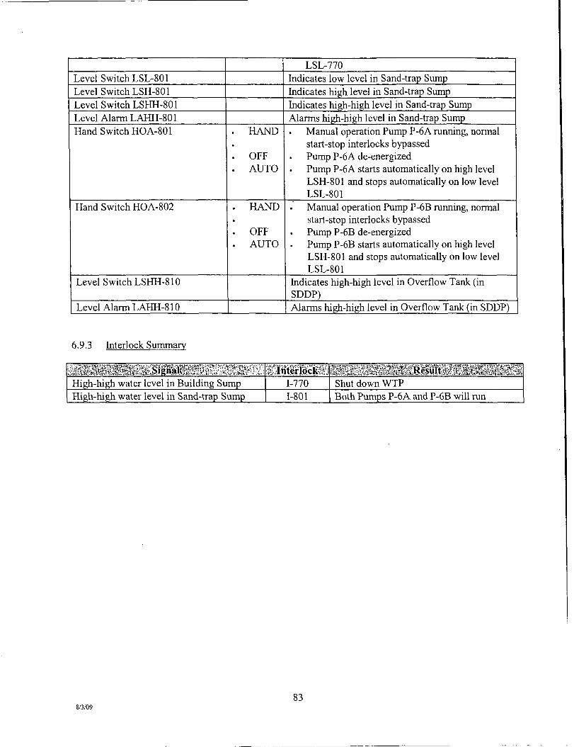
Level Switch LSL-801 Level Switch LSH-801 Level Switch LSHH-801 Level Alarm LAHH-801 Hand Switch HOA-801
Hand Swhch HOA-802
Level Switch LSHH-810
Level Alarm LAHH-810
. HAND • . OFF . AUTO
. HAND • . OFF . AUTO
LSL-770 Indicates low level in Sand-trap Sump Indicates high level in Sand-trap Sump Indicates high-high level in Sand-trap Sump Alarms high-high level in Sand-trap Sump
Manual operation Pump P-6A mnning, nonnal start-stop interlocks bypassed Pump P-6A de-energized Pump P-6A starts automatically on high level LSH-801 and stops automatically on low level LSL-801 Manual operation Pump P-6B mnning, normal start-stop interlocks bypassed Pump P-6B de-energized Pump P-6B starts automatically on high level LSH-801 and stops automatically on low level LSL-801
Indicates high-high level in Overflow Tank (in SDDP) Alarms high-high level in Overflow Tank (in SDDP)
6.9.3 Interlock Summary
isit&Mml!s;ssi;#:;SignM?^^ High-high water level in Building Sump High-high water level in Sand-trap Sump
iliitlicii 1-770 1-801
iiSS iiSi E^feSiSfe&ResulMsfiSfe:, Shut down WTP Both Pumps P-6A and P-6B will mn
83 8/3/09

7.0 OPERATIONS
7.1 Introduction
The Operations Section of this Plan has been divided into six primary subsections: Influent Process Water Pumping, Multi-media Sand Filtration, Bag Filtration, Cartridge Filtration, Granular Activated Carbon Adsorption and Treated Effluent Discharge. The major equipment for each subsystem is defined with respect to its applicable operating parameters and specifications. All issues pertaining to safety within any subsystem are addressed in Section 5.0, Health and Safety.
Appendix D, Manufacturers' O&M Manuals, contains copies of the O&M information for the major equipment components.
Set points for all equipment can be found in Section 6. Although set points have the potential for change over time, the Start-Up and Testing procedures will act as a good base and reference.
The Master Equipment List, located in Appendix D, is a summary of all pertinent information relative to the treatment/process equipment. The Operator is also directed to the on-site computer copy ofthis list for information on all WTP equipment.
7.2 Influent Process Water Pumping
7.2.1 Equipment Specifications
Refer to Manufacturer's O&M Manual (Appendix D) for further information.
Process Pumps
Pump No.: Type: Make/Model: Discharge Pipe: Motor HP: Motor Speed: Motor Rating
Flow hidicator
Tag No.: Meter Size: Min-Max Flow:
P1A,P1B, andPlC Suction End Centrifugal Gorman Rupp VGH8D31-B 10" x 8" or equivalent Standard wall thickness carbon steel 200 HP 1550 rpm 460V, 3 Ph, 60 Hz
FIT-304 18 in. 0-6000 gpm
7.2.2 Operation and Controls
The water treatment system begins at the main process pumps. These pumps will be housed in the SDDP so that their location will be in close proximity to the water buffer tanks located within the SDDP. The two water buffer tanks are part of the SDDP. The WTP will have a dedicated level control system within one of the water buffer tanks to control the main process pumps. In addition, to prevent water buffer tank overflow, the SDDP system will also have an independent level alarm acting as an interlock to the SDDP process should the water buffer tank being pumped from ever reach a high-high level condition.
84 8/3/09

The main process pumps will consist of three 200-hp Gorman Rupp end suction centrifugal pumps each capable of 3,000 gpm. Each pump motor will be controlled by an interconnected variable frequency drive (VFD). Under normal operating conditions, two pumps will be kept mnning (each handling 50 percent of the desired flow) and the motor speed will be controlled to maintain a pre-set low level within the water buffer tanks. A minimum flow rate of 3,000 gpm will be maintained at all times; if necessary, the pumps will shut off for a period of time to allow the level in the tank to rise if a 3,000 gpm withdrawal cannot be maintained.. The VFDs will be linked so that both pumps will be mn at the same speed when in parallel operation. The pumps will be operated in this manner for flows up to 6,000 gpm.
The third redundant pump will be installed as a spare in case of a failure of one of the other two pumps. A single magnetic flow meter on a common discharge line will measure the total combined flow into the WTP.
Water Buffer Tank 1 is provided with four (4) control functions: Level Measurement (LE-301) High Level Switch (LSHH-301), Low Level Switch (LSLL-301), and pH Measurement (AE-301).
7.3 Multi-media Sand Filtration
7.3.1 Equipment Specifications
Refer to Manufacturer's O&M Manual (Appendix D) for further information.
Muhi-Media Filters SFOl through SF24
Model: TIGG C-500 or equivalent
No. of Filters: 24 Size: 8 foot diameter, 10' 5" height; each Material of Constmcfion: Carbon Steel (ASTM 516 grade 70) Valving: Pneumatically actuated valves Max Working Pressure: 125 psig @ 115 deg F Flow Mode: 325 gpm per vessel (Design) 400 gpm per vessel (Maximum) Backwash Mode: 600 to 780 gpm typical Media: (From top of vessel)
• 6800 lbs of gravel • 2175 lbs of garnet • 5000 lbs of sand • 3750 lbs of anthracite
Accessories: Flow measurement (1 per vessel). Differential pressure transmitter (1 for all 24 vessels)
7.3.2 Operation and Control
Sand filtration will consist of (24) 8-foot-diameter vessels with an approximate media capacity of 20,000 pounds and a cross-sectional area of 50 square feet. These vessels are TIGG Model C-500. The filter vessels will each contain four filter media including, gravel, garnet, sand, and anthracite, which will result in approximately 5-niicron nominal filtration efficiency. The multiple filter media within each vessel have varying gradations in particle size that allow for greater depth of filtration through the filter bed and increase the amount of operating time between backwash events.
85 8/3/09

These vessels will be laid out in three treatment trains of eight vessels per train. Piping and valving will be arranged to allow as few or as many vessels to be online at one time. A complete treatment train can be isolated and kept in reserve or each individual vessel can be isolated as needed.
The maximum hydraulic capacity of the sand vessels will be 400 gpm each. At 6,000 gpm and 16 vessels online, the filtration rate is a maximum of 7.5 gpm per square foot, which is consistent with standard practice and within the hydraulic capacity of these vessels. Placing more vessels online (up to a total of 24) will result in increased efficiency (to 5 gpm per square foot), less frequent backwash, and reduced head loss.
As described in the process flow description for the SDDP, water exiting the pre-thickener tanks will have a maximum TSS load of 50 ppm. Backwash of the multi-media sand filters will be performed one vessel at a time, in a sequential manner, based on a reduction in flow tlirough the filters or on differential pressure across the filters. Each filter vessel will be equipped with a flow sensor that will detect a reduction of flow as the solids loading on the vessel increases. At a pre-set flow rate, backwash of the vessel will be initiated automatically. The differential pressure across all of the multi-media filter vessels will also be continuously monitored. Upon reaching a pre-set high differential pressure level, a backwash sequence will automatically be initiated. Backwash supply water will be pumped from the effluent tank using dedicated backwash pumps at approximately 20 gpm per square foot, equivalent to 1,000 gpm. Presently, however, operational experience has shown that a 600 gpm backwash rate is adequate to backwash the multi-media sand filters. The manufacturer recommends using a backwash rate in the range of 720 to 780 gpm. A typical backwash is 10 to 22 minutes per vessel. Valves on the muhi-media filter vessels will be automatic, air actuated type. Alternatively, the Plant Operator can initiate a backwash from the system PLC. Backwash water will be retumed to the overflow tank in the dewatering facility for further processing.
7.4 Bag Filtration
7.4.1 Equipment Specifications
Refer to Manufacturer's O&M Manual (Appendix D) for further information.
Bag Filters BFl through BF6
Model: Cuno 12ME2BFGAB or equivalent
No. of Filters 6 vessels (12 bag filters per vessel) Type: NB Bags (All polypropylene filter bags with polypropylene collar) Size: 10 um (nominal) #2 size Materials of Constmction: 304 Stainless Steel Design Pressure: 150 psig @ 250 deg. F
7.4.2 Operation and Control
Bag filtration will consist of six multi-bag filter vessels. Each vessel will contain 12 individual bag filters. These vessels will be Cuno Model No. 12 ME. Bag filter efficiency rating will be 5 micron nominal or less. Actual efficiency rating of the multi-bag filters will be detemiined in the field to balance maximum filter efficiency with a reasonable operation and maintenance time for filter change-out. The multi-bag filter vessels will be arranged in three treatment trains of two vessels each. Piping and valving will be arranged to allow any number of vessels to be operated simultaneously. An entire treatment train can be isolated and kept in reserve, or individual vessels can be isolated as needed.
86 8/3/09

The maximum hydraulic capacity of each multi-bag filter vessel is 1,750 gpm. Under nomial operations, at least one of the six vessels will be offline for filter change-out. The differential pressure across all of the multi-bag filter vessels will also be continuously monitored. When indicated by a high differential pressure in any of the online vessels, a switch will be made to place the offline vessel with clean muUi-bag filters into operation and take the vessel with spent bag filters out of operation, allowing for bag change-out. This will be a manual vessel switchover initiated by the Operator; however, a high differential pressure switch across all vessels v/ill activate an annunciator on the PLC to notify the Operator that a switch over is required.
7.5 Cartridge Filtration
7.5.1 Equipment Specifications
Refer to Manufacturer's O&M Manual (Appendix D) for further information.
Cartridge Filters CFl. CF2, CF3
Model: Cuno 12HF60HBGD or equivalent
No. of Filters 3 vessels (12 filters per vessels) Type: High Flow Filter vessel (12 - 60" high flow filter cartridges per vessel) Size: 10 um (absolute) pleated polypropylene filter media. Cartridge is 60" in
length and 6.5" diameter Materials of Constmction: 304 Stainless Steel Design Pressure: 150 psig @ 250 deg. F
7.5.2 Operation and Control
Cartridge filtration will consist of three high-flow cartridge filter vessels. Each vessel will contain 12 individual cartridge filters. These vessels will be Cuno Model No. 12HF60HBFD. Cartridge filter efficiency ratings will range from 1 to 70 microns, absolute. Actual efficiency ratings of the cartridge filters will be determined in the field to balance maximum cartridge filter efficiency with a reasonable operation and maintenance time for filter change-out.
The cartridge filter vessels will be arranged in three treatment trains of one vessel each. Each vessel will be rated for a maximum hydraulic flow of 3,500 gpm. Any number of cartridge filter vessels can be operated simultaneously, or individual filter vessels can be isolated as needed. In addition, piping and valving will be arranged to allow the cartridge filters to be operated either upstream or downstream of the activated carbon adsorbers.
Under normal operations, at least one of the three vessels will be offline for filter change-out. The differential pressure across all of the cartridge filter vessels will also be continuously monitored. When indicated by a high differential pressure in any online cartridge filter vessel, a manual switch will be implemented to put the offline vessel with new cartridge filters into operation and take the vessel with spent cartridge filters out of operation for change-out. This will be a manual vessel switchover initiated by the Operator; however, a high differential pressure switch across all vessels will activate an annunciator on the PLC to notify the Operator that a switchover is required.
87 8/3/09

7.6 Granular Activated Carbon Adsorption
7.6.1 Equipment Specifications
Refer to Manufacturer's O&M Manual (Appendix D) for further information.
Liquid Phase Activated Carbon GFl through GFl 8
Model: Calgon Modular Model 10 Adsorption System or equivalent No. of Vessels: 18 (9 pairs in series) Size: 10-foot diameter, 21.75-feet overall height; each Capacity: 700 gpm per pair in series (6300 gpm total in series) Constmction: Carbon steel (ASTM 516 grade 70) Valving: Manually controlled Mounting: four (4) stmctural steel support legs Carbon: Virgin, Calgon Filtrasorb 300
7.6.2 Operation and Control
The activated carbon process will consist of nine dual-unit carbon adsorbers. Each dual-unit carbon adsorber consists of two vessels containing 20,000 pounds of carbon each and can be operated in parallel or series. Each dual-unit is rated for a maximum hydraulic capacity of 1,400 gpm in parallel or 700 gpm in series. The empty bed contact time is approximately 8 minutes in the primary vessels and 16 minutes overall (both primary and secondary vessels) at 6,000 gpm.
Series Operation The carbon adsorption system has been sized to mn in series at the peak design flow rate of 6,000 gpm. Series operation has the advantage of being able to monitor for breakthrough of contaminants at the midpoint between the primary and secondary vessels. In the case of breakthrough of the primary carbon vessel, the breakthrough will be detected and a change-out of the primary carbon vessel can be initiated. Contaminants that break through the primary vessel will be captured on the secondary vessel instead of being discharged to the river. Initial carbon breakthrough sampling will be performed on a monthly basis. This frequency may be adjusted during operations to optimize performance monitoring. Carbon breakthrough sampling will include, at a minimum, grab samples at the carbon influent and in between series carbon vessels. At the expected low levels of PCB concentrations in the water, useful life for each of the carbon adsorber vessels is several years. It is possible, however, that other constituents in the water may affect the time to breakthrough. Sampling will be conducted at the vessel pair which has the greatest operation online time and/or greatest total flow. Additional vessel pairs may be sampled if deemed necessary. Carbon adsorber vessels in series will be switched from upstream to downstream position when the PCB level in between is approximately half of the typical PCB concentrafion in the influent water.
At the peak design flow of 6,000 gpm, all nine dual units can be operated in series. At lower flows, unhs can be taken offline and put into reserve, or alternatively all nine dual units can be operated at lower flow rates, increasing the contact time and performance.
Backwash The carbon adsorbers will be piped and valved to allow the vessels to be manually backwashed if it becomes necessary due to solids loading. Differential pressure will be measured at each carbon vessel, and a high differential pressure switch will activate an armunciator on the PLC to notify the Operator that
88 8/3/09
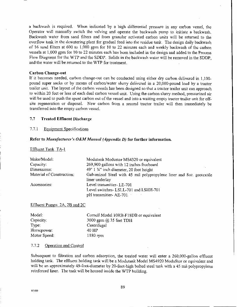
a backwash is required. When indicated by a high differential pressure in any carbon vessel, the Operator will manually switch the valving and operate the backwash pump to initiate a backwash. Backwash water from sand filters and from granular activated carbon units will be retumed to the overflow tank in the dewatering plant for gradual feed into the residue tank. The design daily backwash of 16 sand filters at 600 to 1,000 gpm for 10 to 22 minutes each and weekly backwash of the carbon vessels at 1,000 gpm for 10 to 22 minutes each has been included in the design and added to the Process Flow Diagrams for the WTP and the SDDP. Solids in the backwash water will be removed in the SDDP, and the water will be retumed to the WTP for treatment.
Carbon Change-out If it becomes needed, carbon change-out can be conducted using either dry carbon delivered in 1,100-pound super sacks or by means of carbon/water slurry delivered in a 20,000-pound load by a tractor trailer unit. The layout of the carbon vessels has been designed so that a tractor trailer unit can approach to within 20 feet or less of each dual carbon vessel unit. Using the carbon slurry method, pressurized air will be used to push the spent carbon out of the vessel and into a waiting empty tractor trailer unit for off-site regeneration or disposal. New carbon from a second tractor trailer will then immediately be transferred into the empty carbon vessel.
7.7 Treated Effluent Discharge
7.7.1 Equipment Specifications
Refer to Manufacturer's O&M Manual (Appendix D) for further information.
Effluent Tank TA-1
Make/Model: Modutank Modustor MS4320 or equivalent Capacity: 269,900 gallons with 12 inches freeboard Dimensions: 49' 1 %" inch diameter, 20 foot height Material of Constmcfion: Galvanized Steel with 45 mil polypropylene liner and 8oz. geotextile
liner underlay Accessories: Level transmitter- LE-701
Level switches- LSLL-701 and LSHH-701 pH transmitter-AE-701.
Effluent Pumps 2A. 2B and 2C
Model: Cornell Model 10RB-F18DB or equivalent Capacity: 3000 gpm @ 35 feet TDH Type: Centrifugal Horsepower: 40 HP Motor Speed: 1180 rpm
7.7.2 Operation and Control
Subsequent to filtration and carbon adsorption, the treated water will enter a 260,000-gallon effluent holding tank. The effluent holding tank will be a Modutank Model MS4920 ModuStor or equivalent and will be an approximately 49-foot-diameter by 20-foot-high boUed steel tank with a 45 mil polypropylene reinforced liner. The tank will be housed inside the WTP building.
89 8/3/09
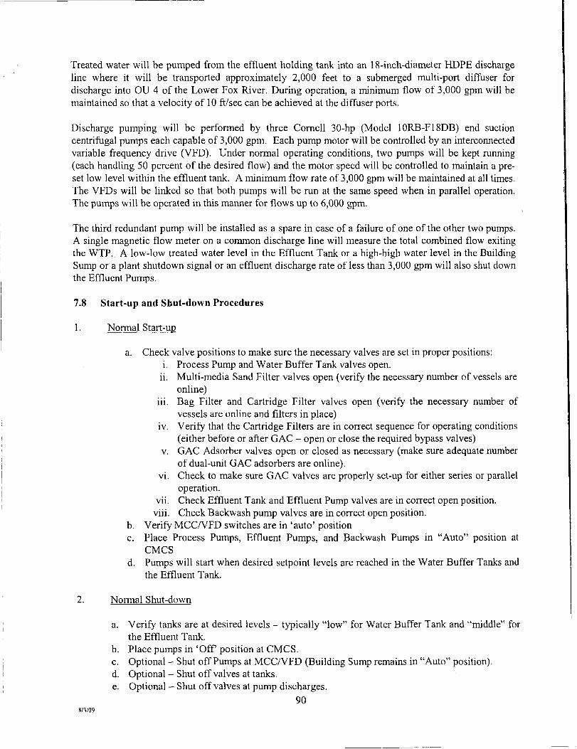
Treated water will be pumped from the effluent holding tank into an 18-inch-diameter HDPE discharge line where it will be transported approximately 2,000 feet to a submerged multi-port difftiser for discharge into OU 4 of the Lower Fox River. During operation, a minimum flow of 3,000 gpm will be maintained so that a velocity of 10 ft/sec can be achieved at the diffuser ports.
Discharge pumping will be performed by three Cornell 30-hp (Model 10RB-F18DB) end suction centriftjgal pumps each capable of 3,000 gpm. Each pump motor will be controlled by an interconnected variable frequency drive (VFD). Under normal operating conditions, two pumps will be kept mnning (each handling 50 percent of the desired flow) and the motor speed will be controlled to maintam a preset low level within the effluent tank. A minimum flow rate of 3,000 gpm will be maintained at all times. The VFDs will be linked so that both pumps will be mn at the same speed when in parallel operation. The pumps will be operated in this maimer for flows up to 6,000 gpm.
The third redundant pump will be installed as a spare in case of a failure of one of the other two pumps. A single magnetic flow meter on a common discharge line will measure the total combined flow exiting the WTP. A low-low treated water level in the Effluent Tank or a high-high water level in the Building Sump or a plant shutdown signal or an effluent discharge rate of less than 3,000 gpm will also shut down the Effluent Pumps.
7.8 Start-up and Shut-down Procedures
1. Normal Start-up
a. Check valve positions to make sure the necessary valves are set in proper positions: i. Process Pump and Water Buffer Tank valves open,
ii. Multi-media Sand Filter valves open (verify the necessary number of vessels are online)
iii. Bag Filter and Cartridge Filter valves open (verify the necessary number of vessels are online and filters in place)
iv. Verify that the Cartridge Filters are in correct sequence for operating conditions (either before or after GAC - open or close the required bypass valves)
V. GAC Adsorber valves open or closed as necessary (make sure adequate number of dual-unit GAC adsorbers are online),
vi. Check to make sure GAC valves are properly set-up for either series or parallel operation,
vii. Check Effluent Tank and Effluent Pump valves are in correct open poshion. viii. Check Backwash pump valves are in correct open position.
b. Verify MCC/VFD switches are in 'auto' position c. Place Process Pumps, Effluent Pumps, and Backwash Pumps in "Auto" position at
CMCS d. Pumps will start when desired setpoint levels are reached in the Water Buffer Tanks and
the Effluent Tank.
2. Normal Shut-down
a. Verify tanks are at desired levels - typically "low" for Water Buffer Tank and "middle" for the Effluent Tank.
b. Place pumps in 'Off poshion at CMCS. c. Optional - Shut off Pumps at MCC/VFD (Building Sump remains in "Auto" position). d. Optional - Shut off valves at tanks. e. Optional - Shut off valves at pump discharges.
90 8/3/09
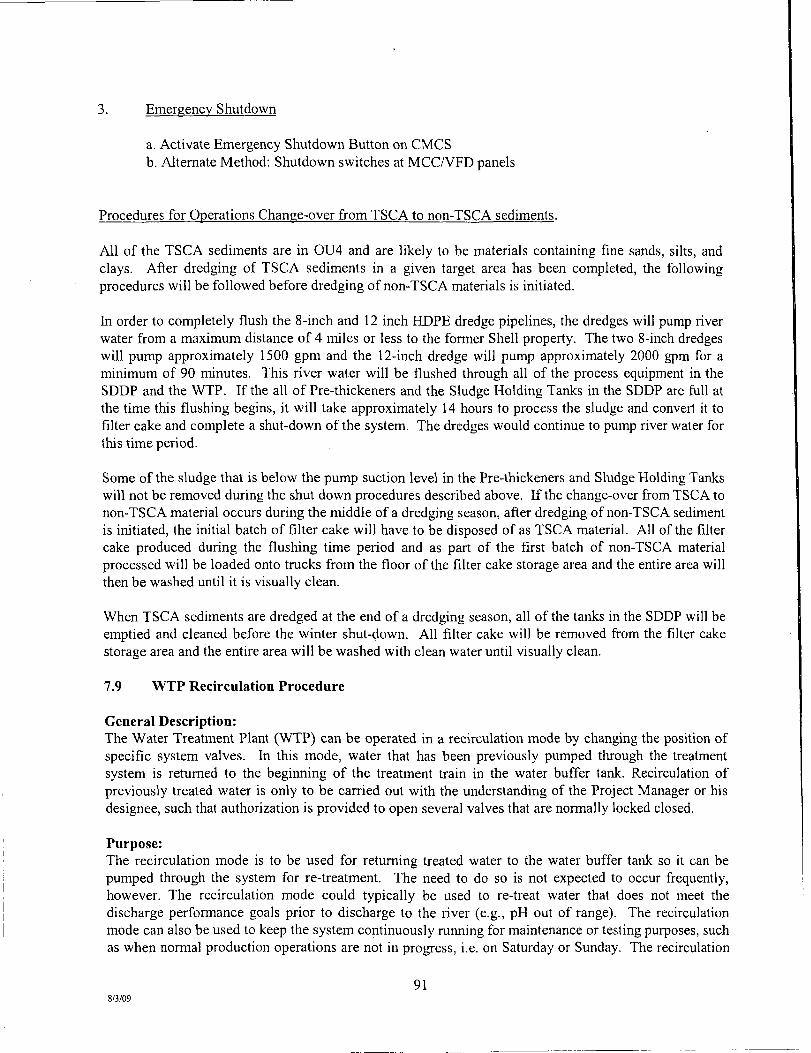
3. Emergency Shutdown
a. Activate Emergency Shutdown Button on CMCS b. Altemate Method: Shutdown switches at MCC/VFD panels
Procedures for Operations Change-over from TSCA to non-TSCA sediments.
All of the TSCA sediments are in 0U4 and are likely to be materials containing fine sands, silts, and clays. After dredging of TSCA sediments in a given target area has been completed, the following procedures will be followed before dredging of non-TSCA materials is initiated.
In order to completely flush the 8-inch and 12 inch HDPE dredge pipelines, the dredges will pump river water from a maximum distance of 4 miles or less to the former Shell property. The two 8-inch dredges will pump approximately 1500 gpm and the 12-inch dredge will pump approximately 2000 gpm for a minimum of 90 minutes. This river water will be flushed through all of the process equipment in the SDDP and the WTP. If the all of Pre-thickeners and the Sludge Holding Tanks in the SDDP are fiill at the time this flushing begins, it will take approximately 14 hours to process the sludge and convert it to filter cake and complete a shut-down of the system. The dredges would continue to pump river water for this time period.
Some of the sludge that is below the pump suction level in the Pre-thickeners and Sludge Holding Tanks will not be removed during the shut down procedures described above. If the change-over from TSCA to non-TSCA material occurs during the middle of a dredging season, after dredging of non-TSCA sediment is initiated, the initial batch of filter cake will have to be disposed of as TSCA material. All of the fiher cake produced during the flushing time period and as part of the first batch of non-TSCA material processed will be loaded onto tmcks from the floor of the filter cake storage area and the entire area will then be washed until it is visually clean.
When TSCA sediments are dredged at the end of a dredging season, all of the tanks in the SDDP will be emptied and cleaned before the winter shut-down. All filter cake will be removed from the filter cake storage area and the entire area will be washed with clean water until visually clean.
7.9 WTP Recirculation Procedure
General Description: The Water Treatment Plant (WTP) can be operated in a recirculation mode by changing the position of specific system valves. In this mode, water that has been previously pumped through the treatment system is retumed to the begirming of the treatment train in the water buffer tank. Recirculation of previously treated water is only to be carried out with the understanding of the Project Manager or his designee, such that authorization is provided to open several valves that are normally locked closed.
Purpose: The recirculation mode is to be used for returning treated water to the water buffer tank so it can be pumped through the system for re-treatment. The need to do so is not expected to occur frequently, however. The recirculafion mode could typically be used to re-treat water that does not meet the discharge perfonnance goals prior to discharge to the river (e.g., pH out of range). The recirculation mode can also be used to keep the system continuously mrming for maintenance or testing purposes, such as when normal production operations are not in progress, i.e. on Saturday or Sunday. The recirculation
91 8/3/09

mode cannot be used during nonnal operational conditions since continuous discharge to the river is required.
Procedure: The dredging and SDDP operations should be inactive before putting the WTP in recirculation mode due to potential impact to dredging and dewatering.
Water levels in both the Water Buffer Tanks and Effluent Tank should be greater than or equal to the normal operational set-points for each tank.
All pumps should be in manual mode and off during changing of valve positions.
Valves requiring either opening or closing based on upon normal operating position:
Valve Designation
18"-BFV-WWR-1 18"-BFV-WWR-2 18"-BFV-BP-8 18"-BFV-BP-9 20"-GV-WBT2
Normal Operating Position Open Locked Closed Closed Locked Closed Locked Closed
Recirculation Operating Position Locked Closed Open Closed Open Open
Figure 7-1 and Figure 7-2 have been prepared to show the subject valve positions during WTP normal operations. Figure 7-3 and Figure 7-4 have been prepared to show the subject valves positions during WTP recirculation operations.
'Walk the lines' - A walk through of the process lines should be conducted prior to starting in recirculation mode to verify that, in addition to the valves listed above, all other valves are in proper position.
Verify that sufficient number of sand, bag and cartridge fihers and carbon adsorbers are online.
Start one effluent pump and one process pump in auto mode to initiate recirculation. With one effluent and one process pump in operation, flowrate should be maintained at 4000 gpm or less for each pump. This is necessary so that the pumps are operated within a range consistent with the manufacturer's recommendations.
Monitor flowrate, water levels in the Water Buffer and Effluent Tanks, differential pressures across bag and cartridge filters, and backwash status of the sand filters. Change out bag and cartridge filters as necessary during recirculation.
When recirculation is complete, based on achieving the desired re-treatment level (e.g., pH is back within the acceptable performance range for discharge) all valves should be retumed to their normal operating positions and WTP operations re-started.
92 8/3/09

^ 1
-Cl8;;-C5-WW-l02 )-
-0 — 0 — 0 - - 0 - - o -
Z
o > r O m
o Z C/)
o c m
o
' 'J f °
-Is J Ii -I?
LOWER FOX RIVER SITE OPERABLE UNITS 2-5 GREEN BAY, WISCONSm
WATER TREATMENT PLANT DESIGN
PROCESS AND INSTRUMENTATION DIAGRAM - NORMAL OPERATIONS -
I t TETRA TECH EC, INC. 133 FEDERAL STREET, ffTH FLOOR BOSTON, MA D2110 r£L : \%^T^ 4»741N FAXi <( i r ) « P . M M
LOWER FOX RIVER PRP GROUP GREEN BAY, WISCONSIN
DCSiCNrf) rrf:
J. rftANcis
DRAWN 01 :
r. l i twa iCUl
CHECKLT) BY:
.1. *;cARAyu;!7o
ftPPRWCD OX:
D E S C fi P r I 0 t, APP 1 OATL
mi
3 ' "
O "
.=1

TO MULTI-WEDIA SAND FILTERS
AND GAC VESSELS
P-3A P-3B , 5 HP 1 5 HP BUILDING SUMP
(SPARE)
FIGURE 7-2 NORMAL OPERATIONS
DO
-HIS 0RA.- . r i3 P.'COLiCED
irJ AUTOCAD
HOT R P ^ I S t M A N U A L L Y
THIS OCCUUEHl IS TME FfiO=CRTT ? r ICnTB r o v IWCR PSP rJIOUP P^EKJtrD Br TTTRA ' G H EC. BJC. ( : t C g . «*3 O PTOvCtO !JPM : H I COvD i ' i : ^ THAI n WU. HOI BE 3£0H0C0CE&. CCPtEO. CB tSSUED T A 7-tPJ> ' * j r r iT -S FRCMM3 IC B t USCO SOLELr r o a r - t t ORIi l l i* ! . PIILHDID ^'UWOSE. »t:D SOL£Lf f O " TNt C iCa j lK^J 0 ^ »L\»£« OF "H I EMCiNi^fflriC *NC CO-JSTRUCTICM OF Tl-E SUBJECT r-SOJECi.
y •>:
LU g s
I E" i O W E S UJ P ;; i
< 3 = ! Di o z _ E ^ lUO =
HI | : ; g :
CO H Z
liJ _ j m
^ i ILI 2 CL O O "
W UJ S I - .
CD
LU tu
a: o X
o
o w
Ul > > •
O LU
o
< (3
< Q
H z < UJ D : s ^
ii to
LLI u o Q:
S W i l AS W0%™
D , P - 1 0 7
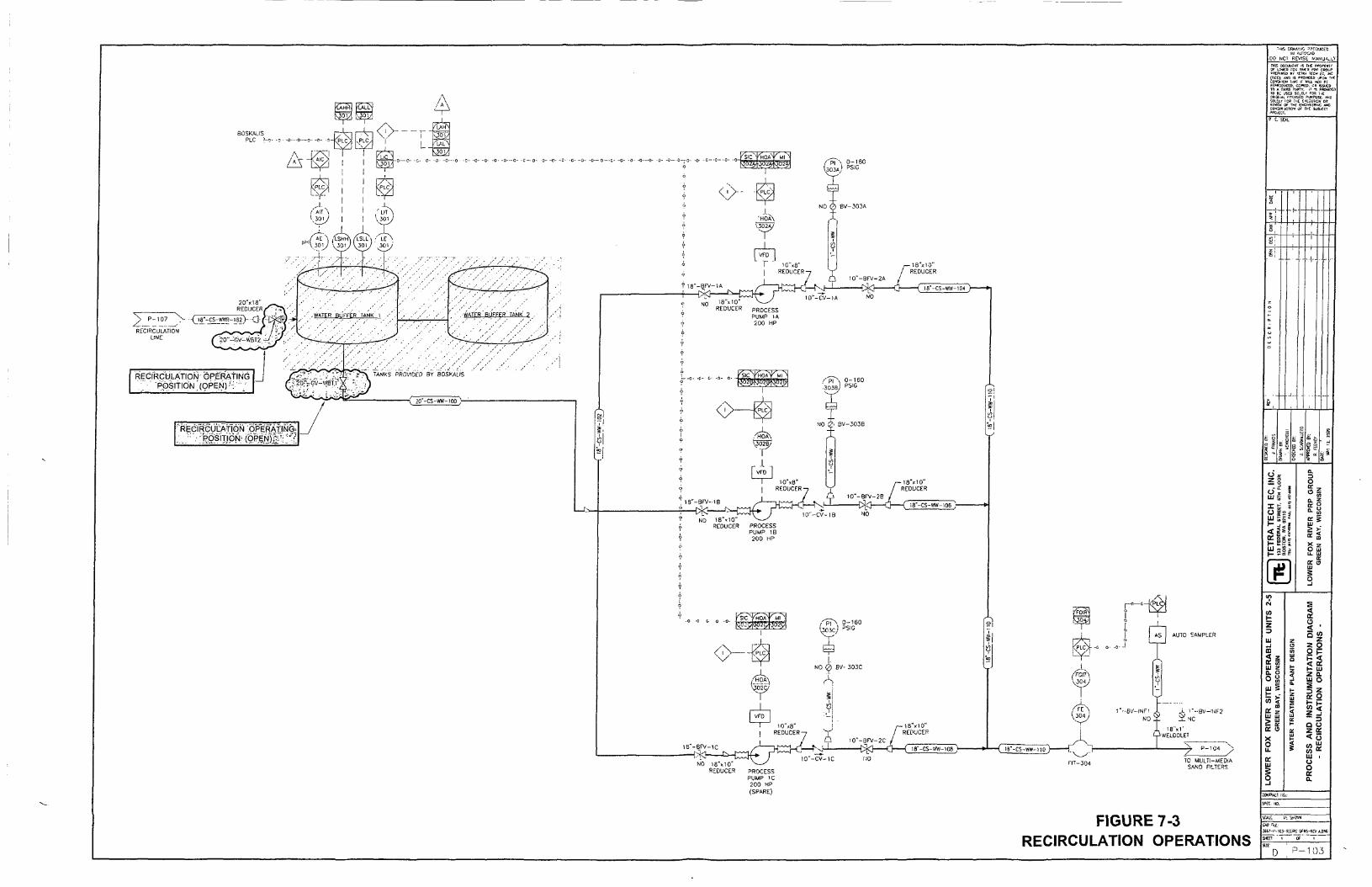
BOSKALIS PLC J-c
C — 0- 0- - p - - 0 - - C ' - 0 -
REDUCER PROCESS PUMP lA 200 HP
c 0- o
13"-BfV-l8
—jk:— NO 1 8 M 0 '
1B'-BF\ ' -1C
NO 18"«10' REDUCER
10" REDUCE!
10"-BP\/ -2C
•C%3 Ci ( I8"-CS-VW-108 ;
NO
l_„_o-f^L^
AS AUTO SAMPLER
A E N| ) " - B V - ) N F I ,
y ° y NO;
- ( iB'-CS-tfW-llO
PROCESS PUMP IC 200 HP (SPARE)
- 7 ' - ' " ' / TO MULTI-MEDIA
SAND FILTERS
FJGURE 7-3 RECIRCULATION OPERATIONS
IM AOTOCAO
DO NCI REVISE ti/AHUA^LV
THIS DGCUUEin <•% T H E V K P V a \ < o r L r w r a FOi; B W R P S P C R « . P o^CPyfllO El- T i r i i TECH I t . P K CTiEC). « 0 IS "WTrtCEO JPSK THE COWDti^H 1H1I I I W:LL NOI PE 3;pR0CuCtl>, CCPiED. Ctl ISSUED 1(1 A TrfRO P^j rY. i> -S PRCWttJl 10 G ; j s t o so.ELT r w H E OR.CII'il. l-nU-'UED PURrt)St. * ^D SOLEli- FOR THE K t C U H I N OR S i M C * Of THE ENCi.vEERitJC AND coiJSrs'jCTKW o r THE i u a j E c i -•TOJECr.
p e. SOL
S t .
(K o i l i ^ w o t r~ t»- •- • HI " S J I— - B K
a o
0. S
UJ
> > 5S
z UJ ..J m
(E 10 Ul Z Q. O OS u j i
^ i Of z UJ Ul > UJ ^ a; D: U X
o u. D: Ul
I
o < ' S <" " 2 2 O 2 K I - Ul 2 a. Ul o
ii
CW 'III:
!H7-|'-1C3-S;CWC OFNS-ftfV KDW
$wn ' T Of T "
•105


8.0 SYSTEM TROUBLESHOOTING
If any portion of the WTP is not operating properly, the Operator will be required to take steps to restore the particular part of the WTP to its proper state of operation. This Section summarizes general actions which can be taken to troubleshoot potential problems. Troubleshooting activities must be performed in compliance with the safety guidelines in Section 5.0, Health and Safety, and applicable Federal and local safety regulations.
For the Operator to troubleshoot the proper operation of the WTP, recognition of the safety hazards and the ability to follow safe procedures, along with the knowledge of how the equipment is supposed to function and the physical and chemical processes involved are required. The following tables provide a brief description of information that can help in troubleshooting. The areas of operation for which troubleshooting guidelines are provided in this section include:
Table 8-1 Table 8-2 Table 8-3 Table 8-4 Table 8-5 Table 8-6
Centrifugal Pump Troubleshooting Tank Level Troubleshooting System pH Troubleshooting Multi-Media Sand Filter Troubleshooting Bag Filter and Cartridge Filter Troubleshooting Carbon Adsorber Troubleshooting
More specific equipment troubleshooting information is provided in the Manufacturer's Operations and Maintenance Manuals located in Appendix D. In conjunction, this information will assist the Operator in locating and eliminating sources of dysfunction in the equipment or process operation. Should the Operator require additional assistance in troubleshooting, Tetra Tech EC will be responsible for providing the additional expertise in the resolution of technical issues relating to operation and maintenance.
Table 8-1 Centrifugal Pump Troubleshooting
iliiiilointillaiiiii: WSM feaial;§lie;6on:ectiyeMictiQBU^ Pump Does Not Operate Switch in "Off Position
Alarm Condition
Circuit Overload
Thermal Overload
Change switch to "Run" or "Auto" Check control panel for alarms which may shut down pump. Check Circuit Breaker at MCC. Reset if necessary. Determine cause of overload. Check thermal overload protection relay at MCC and reset if necessary. Determine cause of overload.
Pump Has No or Low Flow Valves Closed Upstream or Downstream
Leak in Pipe
Flow Control Setting Too Low
Shut off pump. Check manual valves up- and downstream of pump, ensure they are in the "Open" position, and restart pump. Shut off pump; repair or replace line. Check VFD operation.
Pump Has High Flow Flow Control Setting Too High Check VFD operation.
8/3/09 97

Table 8-2 Tank Level Troubleshooting
Level Too High or Low Malfunctioning Pump Operation Refer to Table 8-1. Malfunctioning Level Element, Transmitter, or Controller
Check, readjust, or replace if necessary.
Table 8-3 System pH Troubleshooting
m^m&mmmmim. pH Too High or Low
ISilliiliiEiaiiiSiili pH probe out of calibration pH Probe Fouled
pH Probe Failure
Wastewater entering plant has pH either too low or too high
Wastewater entering plant has pH within the correct range but pH of wastewater leaving the plant is out of range
Recalibrate pH probe Manually check pH of sample to determine if reading is accurate. If not, remove and clean pH probe according to manufacturer's recommendations. If cleaning does not alleviate improper readings, replace probe with spare and monitor. Determine the cause of wastewater entering the plant that is outside of proper pH range. Determine the cause of wastewater that is outside of proper pH range within the plant.
Table 8-4 Multi-Media Filter (SFOl through SF24) Troubleshooting
^fr;',;-;,-..,!!! i^-'.r;-„.-'i '-y* ;r.'.nr-./. -:i;ji;it .-'.-"'">
High Inlet Pressure
High Differential Pressure
Backwash Sequence Fails to Initiate
High Solids Content in Filter Effluent
wMmmmMmimmi Valves Closed Upstream or Downstream Backwashing Required
Backwashing Required
Timer, Differential Pressure or Flow Indicator Setpoints Not Appropriate Water Level in Effluent Tank Too Low
Charmeling Occurring in Media
1!:••i\•ilS'S-:r'•r. '•.:!^•r'.r..:~;0;x,••J•^c^I:.:i^f;'^^^^^
Check valves upstream and downstream of units and ensure they are in the "Open" position. Check differential pressure and flow indicator setpoints. Manually initiate backwash if necessary Check automatic backwash setpoint and adjust if necessary. Manually initiate backwash and monitor. Check setpoints and readjust if necessary.
Check level of water in Effluent Tank. If necessary, adjust level setpoints within effluent tank. Monitor to ensure water level in Effluent Tank is adequate. Manually initiate backwash sequence to redistribute media. Monitor effluent.
98 8/3/09

Table 8-5 Bag and Cartridge Filter (BF1-BF6 and CF1-CF3) Troubleshooting
liiiiiiiiSlilSiil High Inlet Pressure Bags Plugged
Valves Closed Upstream or Downstream
a;i*!KU';.;K?».'rtSievJ^l^^s-J^Si(-=;-i
Check differential pressure. Check filter bags and cartridges and replace if necessary. Check valves upstream and downstream of filters and ensure they are in the "Open" position.
Table 8-6 Carbon Adsorber Troubleshooting
'.'-;:'' , , P r o b l e r a i l l i S i i I High Inlet Pressure
mmmmmmmm:wmm: Valves Closed Upstream or Downstream
Solids Buildup in Units
Check valves upstream and downstream of units, and ensure they are in the "Open" position. Backwash units according to manufacturer's recommendations (see Appendix D). Check operation of Multi-Media Sand, Bag, and Cartridge Filters to determine if carryover is occurring.
8/3/09 99

9.0 EQUIPMENT MAINTENANCE
First and foremost, it is imperative that all operations and maintenance tasks be perfonned with strict adherence to the Site Health and Safety Plan.
The key to good maintenance is regular and systematic inspection of all equipment. Inspection frequency and preventative maintenance is determined by the process application and local conditions such as temperature, dust and operation runtime. The Daily Inspection Form, Appendix A, Report Forms is provided as the documentation format for the Operator's use during daily shift inspections.
A sound program carried out by qualified individuals will greatly increase equipment reliability and productivity. The manufacturers' instruction manuals, referenced m Appendix D, Manufacturers' O&M Manuals and located on-site, must be carefully studied by the Operator before any attempt is made to service a particular piece of equipment.
Master Equipment List, Appendix D, has been created to act as a quick reference for the Operator to all necessary maintenance information. The list is an electronic spreadsheet defining all major equipment, instruments and valves with respect to part number, equipment description, vendor name and contact telephone number.
9.1 Alarm Responses
The CMCS system as described in Section 6.0, Process Description and Operation interfaces directly with the process equipment and identifies emergency/alarm conditions in the WTP. In the event of an alaiTn condition a visible alarm signal will display on the CMCS system. In the event of an alarm condition that remains unacknowledged after a set amount of time, an autodialer system will initiate a series of phone calls to alert altemate personnel of alarm conditions so that corrective action may be taken.
9.2 Maintenance Procedures and Recording
A total maintenance program has been developed for the process equipment which combines corrective and preventative maintenance. The preventative maintenance and frequency information for each piece of equipment is included in Appendix D, Manufacturers' O&M Manuals. Recording of performed maintenance tasks is to be documented on the Equipment Maintenance Form, Appendix A, Report Forms for each piece of equipment.
It is important to note that all operations and maintenance tasks be performed with strict adherence to the HSP.
9.2.1 Tools, Equipment, and Supplies
To maintain and repair equipment, the proper tools must be readily available on-site. A complete list of available site tools is included as Appendix B, Tools and Equipment List.
Spare parts, lubricants and other supplies necessary for routine equipment repairs and maintenance are to be stocked in the WTP. A spare parts inventory list is included as Appendix C, Spare Parts Inventory. Manufacturers' recommended parts constitute most of the list.
Seasonal building and grounds-keeping equipment, such as snow shovels, are to be stored on-site and maintained when not in use.
8/3/09 100

9.2.2 Housekeeping
The plant should be kept in a neat and orderly appearance to provide a safe and pleasant working environment. To maintain a clean and safe workplace, the Operator should create a housekeeping plan and schedule. The housekeeping tasks should include both interior and exterior work. Daily yard pickup and inside sweeping, weekly mopping, along with seasonal snow removal will be performed by plant staff
9.2.3 Lubrication
Proper lubrication of motors and bearings will insure longer equipment run time and efficient operation. Recommended lubrication intervals and types of oils and greases as supplied by the vendor are to be followed. The schedules will be adjusted to conform to heavier usage of the equipment.
Lock-out and tag-out (LO/TO) safety procedures will be followed during all equipment maintenance in accordance with requirements specified in Section 5.0, Health and Safety. Some of the motors and fan bearings, however, must be greased while in motion; Safety procedures applicable to this energized maintenance are to be followed.
Under or over lubrication of bearings can be harmfiil to their life expectancy. Excessive grease will cause the bearings to slide rather than rotate, increasing friction and causing heat buildup. The following general instructions are recommended:
1. Assure that the grease gun tip is clean.
2. Clean the grease fitting with a clean rag. If a plug is to be removed, clean the area round the plug before removal of plug and inserting grease fitting.
3. Remove any relief plug or vent before pumping in grease.
4. Pump the proper amount of grease indicated by information found in the manufacturer's instructions. This information is included (along with frequency of greasing) in the manufacturer's operation and maintenance manuals referenced in Appendix D, Manufacturers' O&M Manuals.
5. Wipe off all excessive grease around unit.
6. Clean vent before replacing vent plug to allow for expansion of grease and to allow excess grease to work out of the bearing.
7. Note in the maintenance records the date, Operator or service personnel and what was done to the equipment.
9.2.4 Storage of Lubricants
An area in the WTP has been designated as a storage area for maintenance lubricants. This area will be configured to prevent any fire or safety hazard and will be posted with "NO SMOKING" signs. Stored lubricants will be tightly sealed to prevent contamination by dust and dirt, and decomposition of the lubricant.
8/3/09 1 0 1

9.2.5 Equipment Rotation
Equipment with multiple pump arrangement (lead/lag sequencing) is automatically run in an alternating fashion so that all pumps maintain approximate equal hours of operation. The CMCS shall monitor and record equipment runtimes to verify that rotation of pumps is operating appropriately.
9.2.6 Electrical
CAUTION: Maintenance work perfonned on exposed live electrical conductors and connections will be done by a licensed electrician using the N.F.P.A. 70 E standard. Routine service to the equipment beyond the Operator's experience, will be performed by 40 Hour trained OSHA field technicians.
9.2.7 Computer Monitoring and Control Svstem (CMCS)
Advantech will provide all initial service needed for the CMCS. An operation and maintenance manual prepared by Advantech is located on-site for general O&M by the Operator. Following the prove-out period a local I&C/electrical service finn, knowledgeable about PLCs, may be retained to provide ongoing troubleshooting and service on an ongoing basis.
9.3 Maintenance Schedule Matrix
A total maintenance program has been developed for the process equipment which combines corrective and preventative maintenance. The preventative maintenance and frequency information for each piece of equipment (Tag No.) has been summarized in a Preventative Maintenance Matrix, Appendix E, Preventative Maintenance Matrix. Recording of performed maintenance tasks is to documented on the Equipment Maintenance Form, Appendix A, Report Forms for each piece of equipment.
It is important to note that all operations and maintenance tasks be performed with strict adherence to Section 5.0, Health and Safety.
9.4 Special Maintenance Procedures
9.4.1 Wastewater or Chemical Spill - Operational Response
Should a large spill of wastewater occur, the Operator shall immediately shutdown the WTP and verify that the wastewater is properly draining to the building sump and that the building sump is operating properly. The Operator should then rectify the cause of the spill and resume plant operation when it is safe to do so. Normal treatment plant operations do not require the use of process chemicals. In the unlikely event of a chemical spill (e.g. cleaning chemicals) the spill should be isolated using absorbent materials or booms. The Operator should consult Health and Safety personnel and review the MSDS to determine further action. If it is determined safe to do and will not adversely affect the WTP processes, the chemical spill may be allowed to drain to the building sump. Dilution water from either the Effluent Tank or potable water service may be required. This will help prevent the spilled chemical from moving through the WTP as a slug and keep urmecessary overloading of the treatment system. If the chemical cannot enter the system, then the chemical shall be properly cleaned up, drummed, and disposed of off-site. Refer to Section 5.0, Health and Safet)' for all safety issues pertaining to chemical spills.
8/3/09 102
9.4.2 Carbon Changeout
Prior to the process of carbon changeout, proper procedures and effluent analytical data must be performed to make a proper decision on when to changeout carbon. Refer to Section 4 ofthis O&M Plan for a nanative on the procedures required for this evaluation.
g/3/09 103

10.0 WASTE TRANSPORTATION AND DISPOSAL
10.1 Background
The Lower Fox River Operable Units 2-5 remedial acUon will result in the generation of waste materials at the Former Shell Property Staging and Material Processing Facility (Green Bay Facility). This section describes the process and methods that will be used to address the safe and compliant handling and transport of generated project wastes from the WTP at the Green Bay Facility. The Green Bay Facility will serve as the central location for processing TSCA and non-TSCA sediments. The Facility will operate 24 hours per day, 5 days per week, Monday through Friday. Maintenance acfivities will be performed on Saturdays or possibly Sundays, if necessary. Wastes at the WTP will consist of spent multi-media sand, spent granular activated carbon, spent cartridge filters, spent bag filters and used personal protective equipment (PPE). It is anticipated that the stored wastes will be non-hazardous and therefore will not require storage and will not require manifests for off-site transportation. The wastes will be manifested as either non-hazardous/non-TSCA waste or as TSCA waste depending on the waste profile, for offsite transportation and appropriate disposal.
10.2 Waste Disposal Criteria and Methods
Before wastes are transported from the Green Bay Facility, they will be sampled and analyzed as described in Section 4 of this document and the associated QAPP Worksheets. This sampling and analysis will comply with the regulatory requirements as well as the requirements of the disposal facilities idenfified in Section 2 ofthis document.
10.3 Waste Disposal Facilities
10.3.1 Disposal Facility for TSCA Wastes The EQ Wayne Disposal Inc. Landfill in Belleville, Michigan is the current designated facility for the disposal of TSCA wastes from the LFR Site. The EQ Wayne Disposal Inc. Landfill operations personnel will provide Certificates of Disposal and original signed manifests to the Generators identified on the manifest no later than 30 days following receipt of the waste. Upon receipt of the Certificate of Disposal, the Generators will contact the facility to verify disposal in accordance with TSCA requirements and maintain a PCB verification Log. The WTP is not expected to generate any TSCA wastes.
10.3.2 Disposal Facility for Non-TSCA Wastes It is anticipated that non-hazardous wastes from the WTP will be transported via trucks and disposed of at the Veolia Hickory Meadows Landfill near Hilbert, Wisconsin. This Landfill is the current designated facility for the disposal of all non-TSCA wastes from the LFR Site. Upon receipt of waste shipments, the Veolia Hickory Meadows Landfill operations personnel will sign the Special Waste Manifest Ticket and issue a weight ticket to the driver who will provide this documentation to the Green Bay Facility operations personnel.
10.4 Waste Transportation Contractor Requirements
All Waste Transportation Contractors (transporters) must use the disposal facilities identified above, or perhaps others, that have been approved in advance by Tetra Tech, the USEPA and WDNR.
10.4.1 Oualifications All waste transporters will be prequalified according to Tetra Tech's regulatory compliance screening process prior to being awarded a transportation subcontract to work on the project . All drivers will have
8/3/09 104

a current commercial driver's license (CDL) with HAZMAT endorsement as required. Addifionally, transporters involved in shipping TSCA and non-TSCA wastes will meet the following USEPA and WDNR requirements:
Completed Notification of PCB Waste Activity submitted to USEPA as a commercial waste transporter and an assigned USEPA Identification Number (required for transport of TSCA or hazardous waste only).
Current registration with WDNR as a Hazardous Waste /PCB Waste Transporter (as applicable) or as a Solid Waste /Recyclables Transporter.
10.4.2 Trucking Equipment Transport vehicles brought to the Green Bay Facility will be in good operating condition and substantially free of mud or other contamination. Owners and operators of transport vehicles will be responsible for maintaining their equipment in a safe operating condition suitable for transport over public roads in accordance with applicable motor canier safety requirements.
Transport vehicles will meet the required specifications for hauling TSCA and non-TSCA wastes. These specifications include use of covers and tight dump bodies to prevent leakage and display of the appropriate USDOT-required placards.
10.5 Waste Quantity Determination
Estimated quantities of wastes likely to be produced will be developed after gaining some operating experience over the first several months of operation in 2009.
10.6 Shipping Documentation
Please refer to Secfion 2.1.5 in the Site Wide O&M Plan.
10.7 Safety
10.7.1 Facility Safety Facility personnel and transporters will receive training in the project-specific SHSP at the Green Bay Facility. The SHSP includes requirements for traffic control, loading/unloading operations, and site rules to follow when driving within the facility.
10.7.2 Public Road Transport Safety Transporters of hazardous and solid waste materials will comply with applicable federal and state regulations for transportation of wastes over public roadways. These regulations include:
USDOT Hazardous Materials Requirements (49 CFR 171-397); USEPA PCB Requirements (40 CFR 761); WDOT Height/Weight, Special and Seasonal Restrictions (s 348); Wisconsin Solid Waste Disposal Act Regulations (NR 500).
10.7.3 Landfill Facilities Safety
Please refer to Section 2.1.5 in the Site Wide O&M Plan.
8/3/09 105

10.8 Spill Response and Contingency Plan
10.8.1 Spill Procedures The primary obligation for reporting and cleaning up a hazardous materials spill that occurs during transportation lies with the owner and operator of the truck from which the material has been released. Tetra Tech will require that transporters of hazardous materials be familiar with the contents of the spill response and contingency plan, comply with all current rules governing the transportation, and have an emergency spill response plan in effect as part of their contract. Drivers will be trained in transportation spill response and be equipped with spill response equipment appropriate for responding to spills of TSCA and non-TSCA wastes. Such response equipment will include a shovel, bags, booms, cones, or other means to demarcate the spill area. Section 12.1 of the Transportation Plan describes the Spill Response and Contingency Plans for waste haulers utilized on the project. Training will also address the general spill response objectives and procedures, which include:
Safeguard life and property Notify the proper authorities Begin containment and cleanup Follow-up with reporting.
10.8.2 Notification Transporters will immediately report spills of hazardous substances in accordance with the WDNR spill reporting requirements. In addition, if a spill of 1 pound or more of PCBs occurs, it will be reported to the National Response center. Spills of greater than 10 pounds or releases of PCBs to water must be immediately reported to the appropriate USEPA Region 5 TSCA Coordinator. Additionally, any transportation incident involving hazardous materials will be reported to the USDOT as required by the regulations.
8/3/09 106
Figure 10-1 Uniform Hazardous Waste Manifest Form
Pt jB tn t i l i i l nn . f iiiiiitmprtl;rm-i»cri*te|Ht*rfi)ttinmi)lafj TUSrSSSW/SrST' T^STJr I. BttyiK* RufinMPtcH' l IMMtmUvi i i
tiiK>b2eM«li
uurQtoiiuz«i;iiouB uftmuMPEcr
l imakAtkni^Wn^UtKt IStwi^ikMrnHUadturntt-awiitai
liRrmilJUjWi,.
1 - . : . - • • : • • •
.i»i.iPr,\[>HMlt
03. E<Till>U*«v
it lantr .MIMMsl i tEt ' iMi iMinl ld^tMti^ 'iVMSm^OHt
yrwituiiiiaClrlg rcsMiUi HurMent wi t»intl . iniawiitfdifait H>>fu«NpiiN*'antf inr IM nfiFy \i l(T<xatlEni.Acnm«;iirti lDaiBil ^^1a^Bl«tBfiuttfDairtBtflrBjHaiHutf[Ufi»pt«fc<ib>iii
U! Inwi iMj Upmn
'taaili)iwftirf'Jr)'Bii*'Sli- n JliTMKJt lipaltMiM.I
1T.T«(«qrJlilmM»UTitfliiaW:rwrtli TnSfSSFTWBITSH'BS" BUib i ' "Ten—IS—sr
Innntrll'^M'TivMMiT* ' ' W ' VUI
H l B .
RIH:
n FilWMtA
UI£,Gf«lDKin<r
Ipiii iniJUhuklcU'ftrSmUil '
1kMia»)aiait^B>ja<>ui<^inMy«tMJ^IU,MlMWtaiil»BiBftiMa«n.ai|Milit<(i?yO«a«iiifi'
f)d.yt>tnyjO<>iy\C«iw«!^ft>iKI»»iw»wti||>t<>»t<»w<HT»WMi»<»WMI>d''.ilinitl D M S«ntn T s n f f — ^
aCSnTSBSS^CmPfT^SSTMEfowBoK^r' DEBtMnO) FACtimr TO SEBTHtCTIQN SIATC (IF HOUIISD)
8/3/09 107

Figure 10-2 Straight Bill of Lading Form
STRAIGHT BILL Of U D U M " S twn FOMi-Oi)gliiB)-lM lte9«(ttH» S t ^ t ^ t t a .
t i t f i f ^ i j r t t * 7kwn*m4mm^t%-9tt^^t^im\t^m0iih'
ecAC, Csmti^Nei tmtmMi,ldlHK'm»ll».mtlVIHtm U « l 4 t A l l w j l 4 t f a U . I ^
. Irar -
^ ^ ^ ^ ^ ^ ^ ^ ^ ^ ? ^ H 3 ^ g 3 p ^ ^ -
8/3/09 108

Figure 10-3 Non-Hazardous Waste Label
-fr.^;^.'-.:
;l^^a^gau<ta.^^l^^;..ffi»iM^nM1?^'^*^T^^»ga!°?;iagagB^^T-'^'J!fc
^iiPii^iipiirw^f
8/3/09 109
Figure 10-4 Hazardous Waste Label
«•<>**•<». • • * > * + * < 1 > « * < > * * * * * * * * « ' » « ^ *
8/3/09 110