Embed Size (px)
Citation preview

S70°14'00"W
N49°46'00"W
111.
63'
S43°51'20"W
145.26'S03°27'55"W
18.97'
207.5
3' As Per S
urvey
79.81'
56.09'
35.0
7'
Ease
.
S 07°19'20" E160.00'
S 82°24'30" W
48
1.5
4'
Due North155.00'
N 44°37'15" E
95.00'
S 89°57'20" E
390.2
0'
N 88°43'50" W
123.6
1'
373.6
1'
250.0
0'
R=65.00'L=100.19' Due North
270.40'
S 14°10'40" E
392.36'
20
2.0
0'
27
9.5
4'
R=555.95' L =319.41'S 07°19'20" E 74.45'
S 25°35'45" W39.05'
416417418419
420
415.5
416
417
418
419
420
415.5
418 41
9
420
418
421
424.5
422.6
424.
5
420.8
422.2
424.
0
420.8
419
420
421
422
423
422
421
420
419
422
421
423
+421.7
+420
.5
420
415.5416
417418
419
423
423
-
BREWSTER, NY 10509 845-278-2110
ENGINEERING & ARCHITECTURE, P.C.
3871 ROUTE 6
P. W. SCOTT DateNo. DescriptionRevisions
Date
Proj. No.
Scale
Drawn by
Project Title
Dwg. Title Seal Dwg. No.
CSCOVER SHEET
10/14/15
PW/MA
AS SHOWN
15-113
LOWENSTEIN, SCMOLKA, CELAJ, CAIPOND DREDGING & REHABILITATION
ARMONK, NEW YORK
FES #
PE
OS #
LOWENSTEIN, SCHMOLKA, CELAJ, CAIPOND DREDGING & REHABILITATION
SITE
A 12/4/15 PER TOWN PLANNERB 12/4/15 ADDED NYSDEC 100' BUFFER
S70°14'00"W
N49°46'00"W
111.
63'
S43°51'20"W
145.26'
S03°27'55"W18.97'
207.5
3' As Per S
urvey
79.81'
56.09'
35.0
7'
Ease
.
S 07°19'20" E160.00'
S 82°24'30" W
48
1.5
4'
Due North155.00'
N 44°37'15" E
95.00'
S 89°57'20" E
390.2
0'
N 88°43'50" W
123.6
1'
373.6
1'
250.0
0'
R=65.00'L=100.19' Due North
270.40'
S 14°10'40" E
392.36'
20
2.0
0'
27
9.5
4'
R=555.95' L =319.41'S 07°19'20" E 74.45'
S 25°35'45" W39.05'
100
' NY
SD
EC
WETLA
ND
SETBA
CK
100
' NYSDEC WETLAND SETBACK
100' NYSDEC WETLAND SETBACK
100' NYSDEC WETLAND SETBACK
416417418419
420
415.5
416
417
418
419
420
415.5
418 41
9
420
418
INLET
OUTLET
INLE
T
INLET
INLE
T
421
424.5
422.6
424.
5
420.8
422.2
424.
0
420.8
419
420
421
422
423
422
421
420
419
422
421
423
+421.7
+420
.5
REMOVE
PRIOR TOANY WORK
REMOVEBENCHPRIOR TOANY WORK
420
415.5416
417418
419
423
423
BREWSTER, NY 10509 845-278-2110
ENGINEERING & ARCHITECTURE, P.C.
3871 ROUTE 6
P. W. SCOTT DateNo. DescriptionRevisions
Date
Proj. No.
Scale
Drawn by
Project Title
Dwg. Title Seal Dwg. No.
SY1OVERALL SITE PLAN
10/14/15
PW/MA
AS SHOWN
15-113
LOWENSTEIN, SCHMOLKA, CELAJ, CAIPOND DREDGING & REHABILITATIONGRAPHIC SCALE
3030 00 6015FES #
PE
OS #
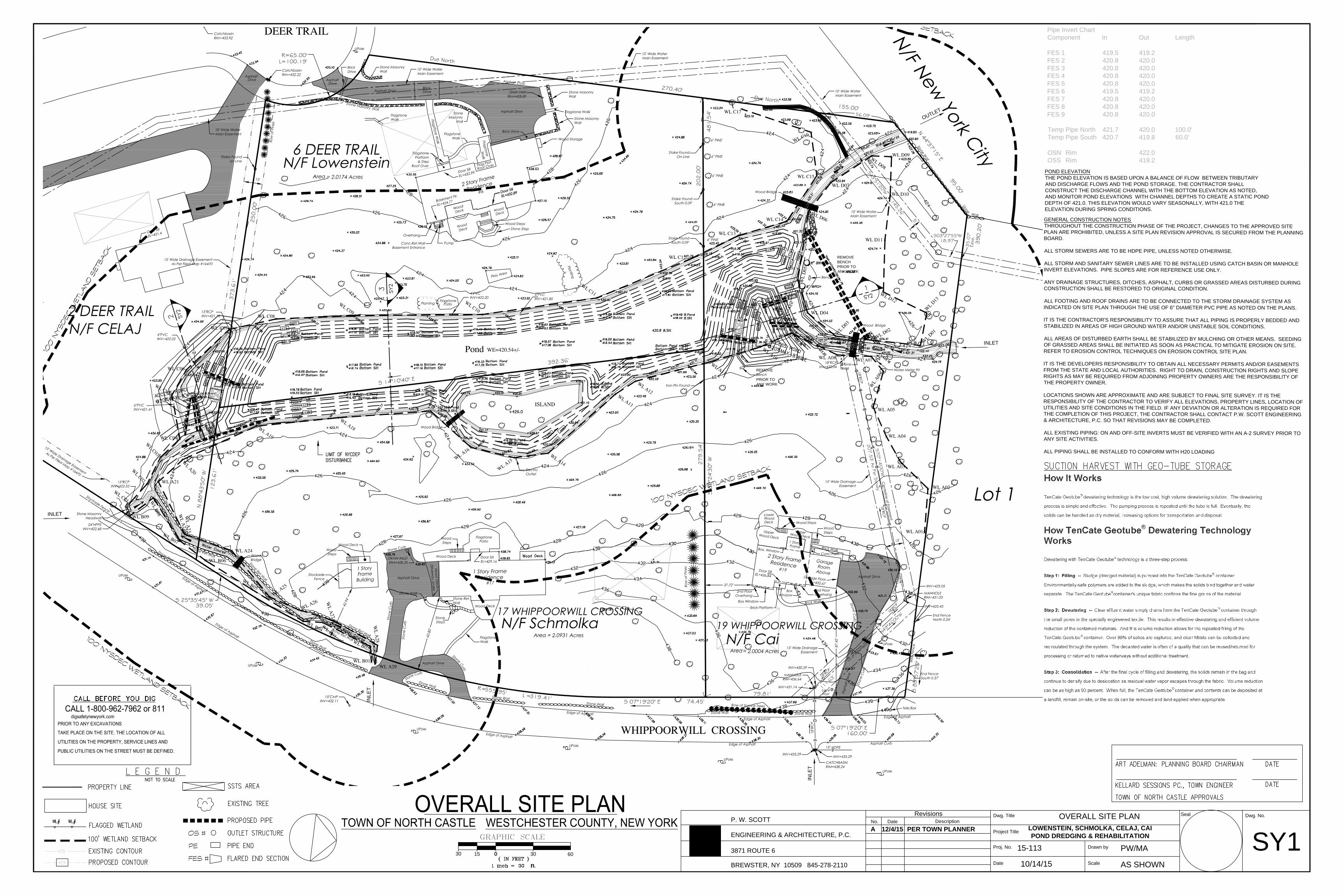
Pipe Invert ChartComponent In Out Length
FES 1 419.5 419.2FES 2 420.8 420.0FES 3 420.8 420.0FES 4 420.8 420.0FES 5 420.8 420.0FES 6 419.5 419.2FES 7 420.8 420.0FES 8 420.8 420.0FES 9 420.8 420.0
Temp Pipe North 421.7 420.0 100.0'Temp Pipe South 420.7 419.8 60.0'
OSN Rim 422.0OSS Rim 419.2
GENERAL CONSTRUCTION NOTESTHROUGHOUT THE CONSTRUCTION PHASE OF THE PROJECT, CHANGES TO THE APPROVED SITEPLAN ARE PROHIBITED, UNLESS A SITE PLAN REVISION APPROVAL IS SECURED FROM THE PLANNINGBOARD.
ALL STORM SEWERS ARE TO BE HDPE PIPE, UNLESS NOTED OTHERWISE.
ALL STORM AND SANITARY SEWER LINES ARE TO BE INSTALLED USING CATCH BASIN OR MANHOLEINVERT ELEVATIONS. PIPE SLOPES ARE FOR REFERENCE USE ONLY.
ANY DRAINAGE STRUCTURES, DITCHES, ASPHALT, CURBS OR GRASSED AREAS DISTURBED DURINGCONSTRUCTION SHALL BE RESTORED TO ORIGINAL CONDITION.
ALL FOOTING AND ROOF DRAINS ARE TO BE CONNECTED TO THE STORM DRAINAGE SYSTEM ASINDICATED ON SITE PLAN THROUGH THE USE OF 6" DIAMETER PVC PIPE AS NOTED ON THE PLANS.
IT IS THE CONTRACTOR'S RESPONSIBILITY TO ASSURE THAT ALL PIPING IS PROPERLY BEDDED ANDSTABILIZED IN AREAS OF HIGH GROUND WATER AND/OR UNSTABLE SOIL CONDITIONS.
ALL AREAS OF DISTURBED EARTH SHALL BE STABILIZED BY MULCHING OR OTHER MEANS. SEEDINGOF GRASSED AREAS SHALL BE INITIATED AS SOON AS PRACTICAL TO MITIGATE EROSION ON SITE.REFER TO EROSION CONTROL TECHNIQUES ON EROSION CONTROL SITE PLAN.
IT IS THE DEVELOPERS RESPONSIBILITY TO OBTAIN ALL NECESSARY PERMITS AND/OR EASEMENTSFROM THE STATE AND LOCAL AUTHORITIES. RIGHT TO DRAIN, CONSTRUCTION RIGHTS AND SLOPERIGHTS AS MAY BE REQUIRED FROM ADJOINING PROPERTY OWNERS ARE THE RESPONSIBILITY OFTHE PROPERTY OWNER.
LOCATIONS SHOWN ARE APPROXIMATE AND ARE SUBJECT TO FINAL SITE SURVEY. IT IS THERESPONSIBILITY OF THE CONTRACTOR TO VERIFY ALL ELEVATIONS, PROPERTY LINES, LOCATION OFUTILITIES AND SITE CONDITIONS IN THE FIELD. IF ANY DEVIATION OR ALTERATION IS REQUIRED FORTHE COMPLETION OF THIS PROJECT, THE CONTRACTOR SHALL CONTACT P.W. SCOTT ENGINEERING& ARCHITECTURE, P.C. SO THAT REVISIONS MAY BE COMPLETED.
ALL EXISTING PIPING: ON AND OFF-SITE INVERTS MUST BE VERIFIED WITH AN A-2 SURVEY PRIOR TOANY SITE ACTIVITIES.
ALL PIPING SHALL BE INSTALLED TO CONFORM WITH H20 LOADING
POND ELEVATIONTHE POND ELEVATION IS BASED UPON A BALANCE OF FLOW BETWEEN TRIBUTARYAND DISCHARGE FLOWS AND THE POND STORAGE. THE CONTRACTOR SHALLCONSTRUCT THE DISCHARGE CHANNEL WITH THE BOTTOM ELEVATION AS NOTED,AND MONITOR POND ELEVATIONS WITH CHANNEL DEPTHS TO CREATE A STATIC PONDDEPTH OF 421.0. THIS ELEVATION WOULD VARY SEASONALLY, WITH 421.0 THEELEVATION DURING SPRING CONDITIONS.
A 12/4/15 PER TOWN PLANNER
BREWSTER, NY 10509 845-278-2110
ENGINEERING & ARCHITECTURE, P.C.
3871 ROUTE 6
P. W. SCOTT DateNo. DescriptionRevisions
Date
Proj. No.
Scale
Drawn by
Project Title
Dwg. Title Seal Dwg. No.
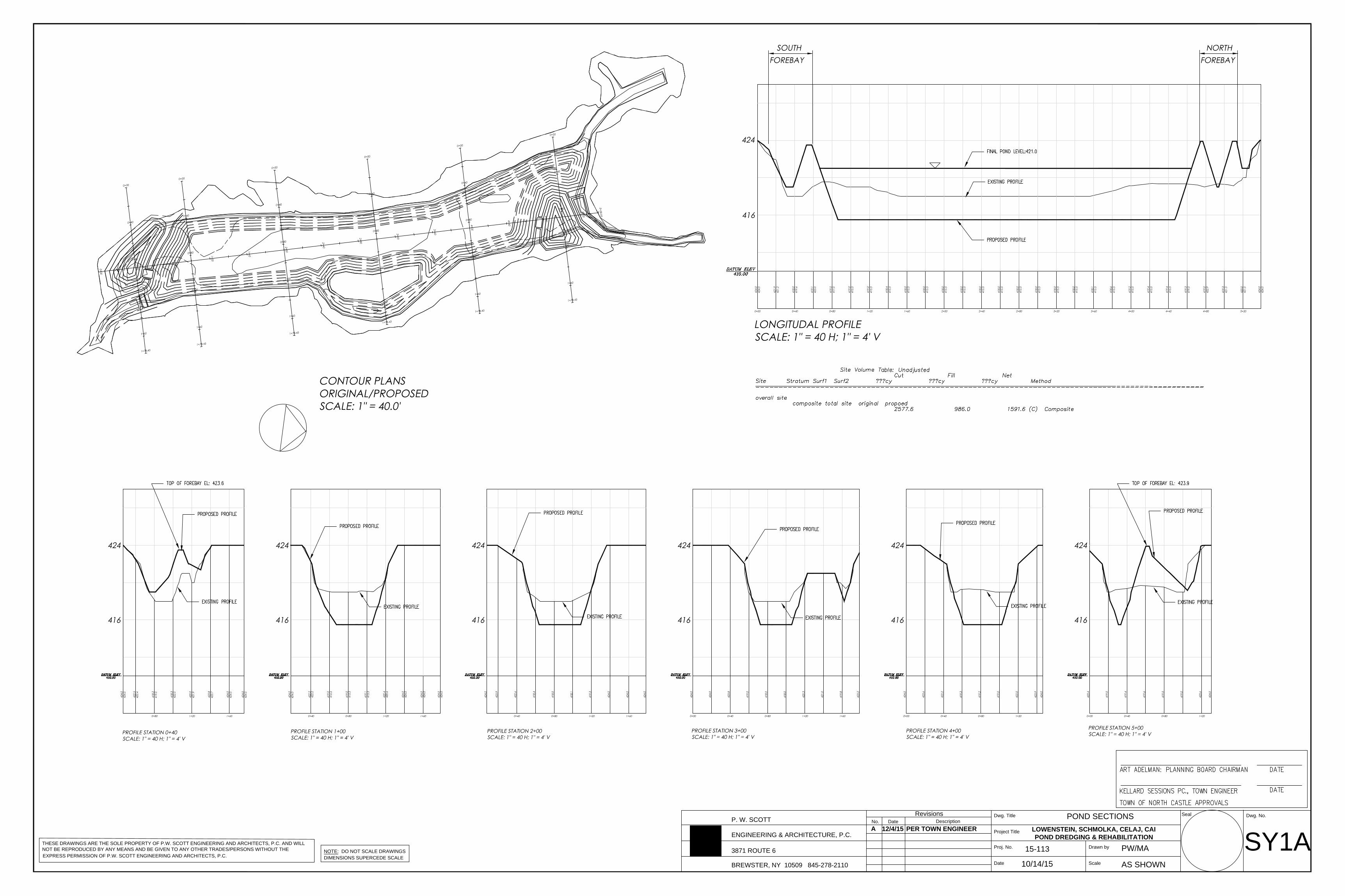
SY1APOND SECTIONS
10/14/15
PW/MA
AS SHOWN
LOWENSTEIN, SCHMOLKA, CELAJ, CAIPOND DREDGING & REHABILITATION
THESE DRAWINGS ARE THE SOLE PROPERTY OF P.W. SCOTT ENGINEERING AND ARCHITECTS, P.C. AND WILLNOT BE REPRODUCED BY ANY MEANS AND BE GIVEN TO ANY OTHER TRADES/PERSONS WITHOUT THE NOTE: DO NOT SCALE DRAWINGS
DIMENSIONS SUPERCEDE SCALE EXPRESS PERMISSION OF P.W. SCOTT ENGINEERING AND ARCHITECTS, P.C.15-113
A 12/4/15 PER TOWN ENGINEER

14' WEIR4' TOP
BOT:6'X4'
BOTTOM OFCHANNEL
D
F
G
EMERGENCYCHANNEL
12
12
2- ANTI-SEEPCOLLARS 10' OC
A
TOP: 90'X36'
12B
C
E
JO
JI
H
20' WEIR
4' TOP
BASE :16'X8'
BOTTOM OFRIP-RAP CHANNEL
F
G
EMERGENCYCHANNEL
13
12
2- ANTI-SEEPCOLLARS 10' OC
A
21
TOP: 56'X44'
JO JI
DC
BH
13
13
PROPOSED DEPTHOR REFUSAL
EXISTING DEPTH2005 SURVEY
BREWSTER, NY 10509 845-278-2110
ENGINEERING & ARCHITECTURE, P.C.
3871 ROUTE 6
P. W. SCOTT DateNo. DescriptionRevisions
Date
Proj. No.
Scale
Drawn by
Project Title
Dwg. Title Seal Dwg. No.
SY2FOREBAY SECTIONS/DETAILS
10/14/15
PW/MA
AS SHOWN
LOWENSTEIN, SCHMOLKA, CELAJ, CAIPOND DREDGING & REHABILITATION
SOUTH FOREBAY CROSS SECTIONSCALE: 1' = 10.0'
12
12
BASIN CONSTRUCTION SEQUENCEREFER TO PROJECT SEQUENCE OUTLINED ON SHEET (SY3B)NOTE: NO SEDIMENTS TO ENTER BASIN DURING CONSTRUCTION &NO STORMWATER TO ENTER BASIN UNTIL SITE IS STABILIZED.INSERT PLUGS INTO OUTLET STRUCTURE OS#6 LOW FLOW HOLES UNTILALL SEDIMENT IN THE BASIN IS REMOVED.
GENERAL NOTESREFER TO DRAWING SHEET (SY3C) FOR SPECIFIC CONSTRUCTION NOTESPER NYSDEC DESIGN SPECIFICATIONS.
ANGLE BASED ON BARREL GRADE91
36" OR 24"DIA. RISER
4"
D = 48" OR 36"
3"
7"
TOP: 16 GA.TOP STIFFNER
2x2x14"
NORTH FOREBAY CROSS SECTIONSCALE: 1' = 10.0'
INV. IN
POND DREDGING CROSS SECTIONSCALE: 1' = 10.0'
INV. OUT
INLET PIPE
INV. IN INV. OUT
INLET PIPE
BERM MATERIAL MUST BEGRANULAR NON-ORGANIC ANDCOMPACTED TO 95% PROCTORLEVELS, ENGINEER OF RECORDRESERVES THE RIGHT TOINSPECT, TEST AND REJECTINSITU MATERIALS ANDREQUIRE IMPORT OFADEQUATE MATERIALS
15-113
A 12/4/15 PER TOWN ENGINEER

S70°14'00"W
N49°46'00"W
111.
63'
S43°51'20"W
145.26'
S03°27'55"W18.97'
207.5
3' As Per S
urvey
79.81'
35.0
7'
Ease
.
100
' NY
SD
EC
WETLA
ND
SETBA
CK
100
' NYSDEC WETLAND SETBACK
100' NYSDEC WETLAND SETBACK
416417418419
420
415.5
416
417
418
419
420
415.5
418 41
9
420
418
INLET
INLE
T
INLET
INLE
T
421
424.5
422.6
424.
5
420.8
422.2
424.
0
420.8
419
420
421
422
423
422
421
420
419
422
421
423
+421.7
+420
.5
REMOVE
PRIOR TOANY WORK
REMOVEBENCHPRIOR TOANY WORK
420
415.5416
417418
419
423
423
BREWSTER, NY 10509 845-278-2110
ENGINEERING & ARCHITECTURE, P.C.
3871 ROUTE 6
P. W. SCOTT DateNo. DescriptionRevisions
Date
Proj. No.
Scale
Drawn by
Project Title
Dwg. Title Seal Dwg. No.
SY10MONITORING & MAINTENANCE PLAN
10/14/15
PW/MA
AS SHOWN
LOWENSTEIN, SCHMOLKA, CELAJ, CAIPOND DREDGING & REHABILITATION
GRAPHIC SCALE
THESE DRAWINGS ARE THE SOLE PROPERTY OF P.W. SCOTT ENGINEERING AND ARCHITECTS, P.C. AND WILLNOT BE REPRODUCED BY ANY MEANS AND BE GIVEN TO ANY OTHER TRADES/PERSONS WITHOUT THE NOTE: DO NOT SCALE DRAWINGS
DIMENSIONS SUPERCEDE SCALE
3030 00 6015
EXPRESS PERMISSION OF P.W. SCOTT ENGINEERING AND ARCHITECTS, P.C.15-113
FES #
PE
OS #
REFER TO DRAWING SY5 FOR EROSION CONTROL NOTES AND SEQUENCE
A 12/4/15 ADDED NYCDEP LINE
WETLAND BUFFER MONITORING AND MAINTENANCE PLAN
1. Wetland Buffer Monitoring & Maintenance PlanThe purpose of the Wetland Buffer Monitoring & Maintenance Plan is to ensure that development in the wetland buffer doesnot compromise the functional integrity of the wetland buffer and the resulting mitigation meets its stated goals as described inthe final resolution adopted by the Town of North Castle ñTownò Planning Board for (the ñPermiteeò).
2. Protocol for Commencement of Wetlands Buffer Monitoring & Maintenance Plana. Permittee shall implement the mitigation plan (wetland buffer plantings) approved by the Town Planning Board.
b. Following the installation of all wetland buffer mitigation in accordance with the final resolution and plans adopted by thePlanning Board, the Permittee shall submit two (2) copies of the following:
i. Certification from a Biologist verifying the proper installation of all plants and materials in accordance with the approvedPlanning Board resolution. The Biologist shall note any deficiencies in the installation of the plant materials or deviationsfrom the approved resolution so that these can be corrected before final approval.
ii. As-built plan prepared by a Licensed Engineer or Licensed Surveyor detailing the (1) locations of plantings and(2) number and species of individual plants.
c. The monitoring period shall begin with the review of all required submitted information/materals and final written approvalby the Town's Wetland Consultant and continue for a period of 5 years.
3. Assurancesa. All plantings and seed mixture applications in conjunction with the mitigation work shall be accomplished in accordance
with the approved drawings and completed within the first growing season after site clean up is complete and topsoil isre-spread on the disturbed areas to be re-vegetated.
b. The Permittee shall ensure that all woody plants in conjunction with the wetlands buffer restoration mitigation plan shallhave a minimum 85% survival of installed plants, which must be met or exceeded at the end of the 2nd (second) growingseason following the initial planting/seeding. If the 85% survival rate is not met at the end of the second growing season,the Permittee shall take all necessary measures to ensure the level of survival by the end of the next growing season,including replanting and re-grading with topsoil, if necessary. Continue the program for the full term of 5 years afterplanting.
4. Monitoring Reportsa. The purpose of the mitigation monitoring and maintenance reports shall be to: (1) evaluate the progress of the
establishment of the mitigation areas, (2) assess compliance with plant survival and plant condition requirements, and (3)identify those aspects of the mitigation areas that may require remediation by the Permittee in order to achieve themitigation objectives.
b. Permittee shall submit the mitigation monitoring and maintenance reports prepared by a licensed landscape architect orenvironmental professional annually no later than November 1st to the Town's Wetland Consultant for review.
c. Information for said reports shall be collected a minimum of seven times: (1) once prior to construction, (2) onceimmediately post construction, and (4) annually for five years post construction between the months of June 1st andSeptember 1st.
d. Minimum Requirements of the Monitoring Reports:i. Identification of the number of surviving approved woody plants and area coverage at the time of the observation. The
report should detail the condition, vigor, size (dbh) of all planted material and compliance with approved Planning Boardresolution.
ii. Color photographs from established stations approved by the Town's Wetland Consultant showing representativeconditions in the mitigation areas taken annually during the designated period defined above.
iii. An estimate of the vegetative cover in the mitigation areas, noting, in particular, areas which are bare of vegetation and/orlocations where erosion and sedimentation are occurring; or where invasive plant species have become established. Aerialcoverage of invasive plant species must be less than 15% of the total wetland buffer mitigation area on the site.
iv. Detailed description of the forebay inlet and overflow outlets noting any soil instability and/or erosion.
v. A qualitative analysis of the extent to which the mitigation has been successful. Said reports shall note areas ofdeficiencies and/or non-compliance and provide recommendations/measures to be taken to ensure continued success ofthe mitigation efforts and soil stabilization.
vi. Additional observations should be noted (e.g., observation of wildlife) and/or information as recommended by the Town'sWetland Consultant.
5. Completion of Monitoring Perioda. Final report submitted by Permittee and certified by the Biologist.
b. The Town's Wetland Consultant will review the submittal material and perform an inspection of the site for conformancewith the approved Planning Board resolution and as-built plans. Upon review and inspection, Town's Wetland Consultantshall submit written approval to the Planning Board.
c. A Monitoring Data Form (in report) shall be filled out that includes above information and the following information ifapplicable:
o The vegetative cover shall be comprised of native species (not invasive species), whether planted or resulting fromnatural colonization. If vegetative cover is less that 85%, replanting shall occur with native species which havesurvived and show good vigor within the wetland buffer mitigation planting areas.
o Elimination of invasive plant species. Invasive species, specifically Japaneses Barberry (Berberis thunbergii) andincluding but not limited to, common reed (Phragmites australis), Japanese honeysuckle (Lonicera japonica), Tartarianhoneysuckle (Lonicera tatarica), bittersweet (Celastrus orbiculatus), and multiflora rose (Rosa multiflora). It isincumbent on the Permittee to remove such invasive species during the appropriate season in which removal isoptimal. Hand removal of any deformed, diseased or otherwise unhealthy plantings and replacement ñin kindò asnecessary to meet the 85% survival threshold.
6. Lawn Areas can be mowed as a permitted maintenance activity.
7. Pesticide and fertilizer use is restricted within the 100 foot buffer from the edge of the Pond Wetland Line as Noted on the plans. The applicant may request a waiver for new plantings as issued by the Town of North Castle as administrative approval.
ADDED M&M PLAN