Embed Size (px)
Citation preview
Low Voltage Power Requirement of TOF FEEs.
• Maximum 110 Watts/tray @ 4.8 Volts @ tray.• Low Noise:
Periodic and Random Distortion (PARD) < few mVRMS • Floating outputs.• Shielded power cables (optional).
• Independent supplies/tray.• Regulation: Not critical (linear regulation on FEE cards).• Remotely controlled and monitored.• Safety: Interlocked and adhere to STAR/BNL safety.• Rack mounted• Relatively low cost.• Good efficiency.
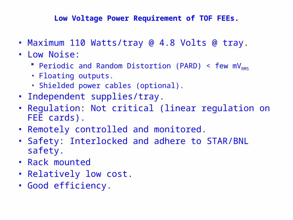
Tray Low Voltage System Configuration
Total of 120 floating outputs arranged in
10 PL
512 chassis
Wiener MDH +
-To Tray
+ sense wire
- sense wire
Tray(load)
+
-To Tray
+ sense wire
- sense wire
< 23 Amperes @ 4.8 Volts (110 watts/tray)
STAR magnet (ground)
Tray(load)Wiener MDH
power cables 2 pairs #10 AWG (4 conductors)(50 mW / parallel pair) < 100 feet
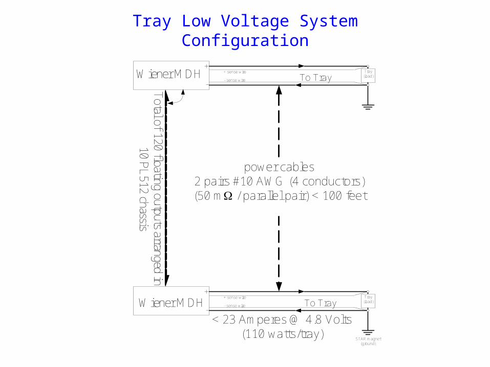
LV Electrical Connection Details
Tray
Chassis
Magnet Ground
10K isolation/safety resistor
Shielded twisted pair with drain wireBelden 6500FE (NEC CMP & CEC FT6, 300 Volt, Flamearrest Jacket)
2 pairs of 10 AWG cable ( Belden 27140A 600 V CEC: FT4 >30 A )
green (ground)
+
-
I < 23 A
Assuming 100 feet cable length and 0.1 volt drop in connectors (no other potential drops).(Note: the cables in the system will be variable lengths, and less than 100')
min 4.8V V
7.2V 6.0V
1.2V
= Fast acting fuse (30 A fast blow fuse either panel mounted by factory or in line with power cable)
The actual type and specs will be supplied when design is finalized
black (hot)
white(neutral)
Interlock and other control signals not shownChassis and magnet ground are connected via low impedence paths.
Sense Wires
Floating power Supply crimp lug connector
AMP 52042-1
P<110 watts
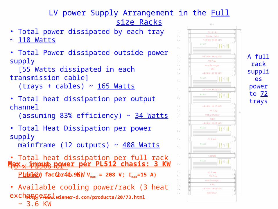
LV power Supply Arrangement in the Full size Racks40 U
40U
Breaker box
1 U Air Intake (empty slot)
1 U
1 U Heta Exchanger
Filter
1 U FAN Tray
1 U Air Intake
3 U
1 U Air Intake
3 U
1 U Air Intake
3 U
1 U
Air Intake (empty slot)
1 U
1 U
Heta Exchanger
Filter
1 U
FAN Tray
1 U
1 U
1 U
1 U
3 U
1 U Air Intake (empty slot)
1 U Air Intake (empty slot)
3 U
1 U Air Intake (empty slot)
1 U Air Intake (empty slot)
Heat Exchanger
FAN Tray
1 U
1 U
1 U
Filter
1 U
Ethernet Switch1 U
Air Intake (empty slot)
3 U
1 U Empty slot
1 U
PL512
PL512
PL512
PL512
PL512
PL512
• Total power dissipated by each tray ~ 110 Watts
• Total Power dissipated outside power supply [55 Watts dissipated in each transmission cable] (trays + cables) ~ 165 Watts
• Total heat dissipation per output channel (assuming 83% efficiency) ~ 34 Watts
• Total Heat Dissipation per power supply mainframe (12 outputs) ~ 408 Watts
• Total heat dissipation per full rack (6 x PL508 or PL512) ~ 2.45 KW
• Available cooling power/rack (3 heat exchangers) ~ 3.6 KW
Max. input power per PL512 chasis: 3 KW
(power factor 0.96; Vmax = 208 V; Imax=15 A)
http://www.wiener-d.com/products/20/73.html
A full rack
supplies power to 72 trays
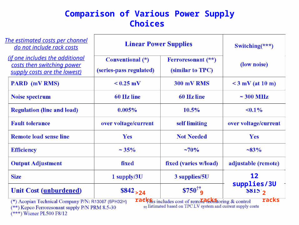
Comparison of Various Power Supply Choices
The estimated costs per channel do not include rack costs
(if one includes the additional costs then switching power supply costs are the lowest)
9 racks 2 racks>24 racks
12 supplies/3U
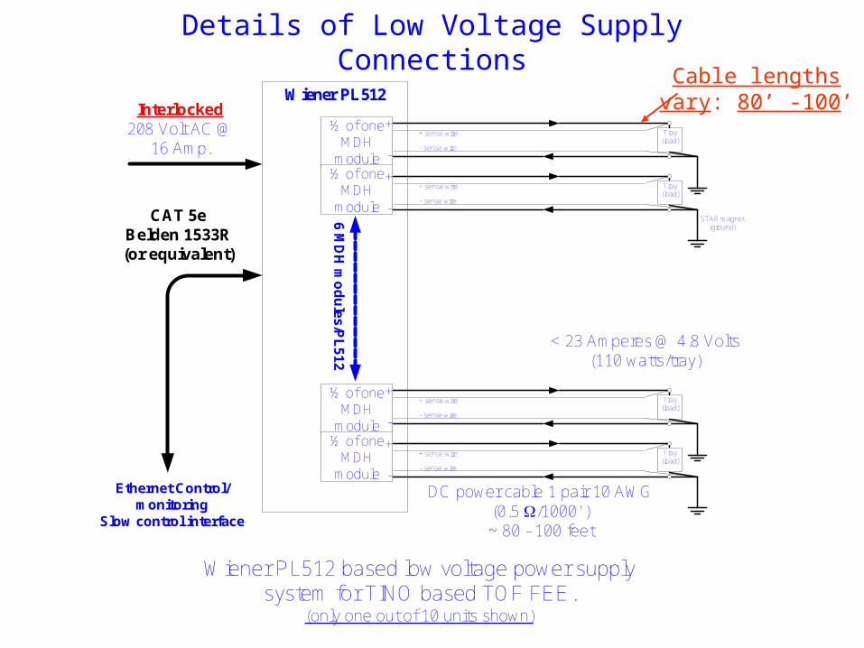
Details of Low Voltage Supply Connections
Wiener PL512
½ of one MDH
module½ of one
MDH module
+
-
+ sense wire
- sense wire
Tray(load)
+
-
+ sense wire
- sense wire
STAR magnet (ground)
Tray(load)
½ of one MDH
module½ of one
MDH module
+
-
+ sense wire
- sense wire
< 23 Amperes @ 4.8 Volts (110 watts/tray)
Tray(load)
+
-
+ sense wire
- sense wire
Tray(load)
DC power cable 1 pair 10 AWG (0.5 W/1000' )~ 80 - 100 feet
Interlocked 208 Volt AC @
16 Amp.
Ethernet Control/monitoring
Slow control interface
Wiener PL512 based low voltage power supply system for TINO based TOF FEE.
(only one out of 10 units shown)
6 MD
H m
od
ules/P
L512
CAT 5eBelden 1533R(or equivalent)
Cable lengths vary: 80’ -100’
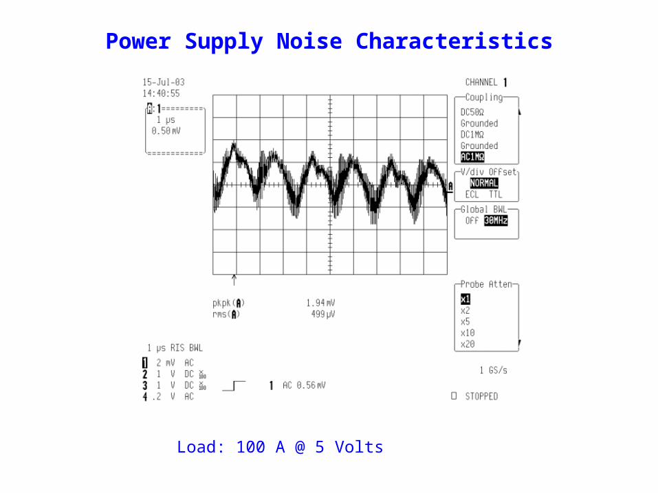
Power Supply Noise Characteristics
Load: 100 A @ 5 Volts
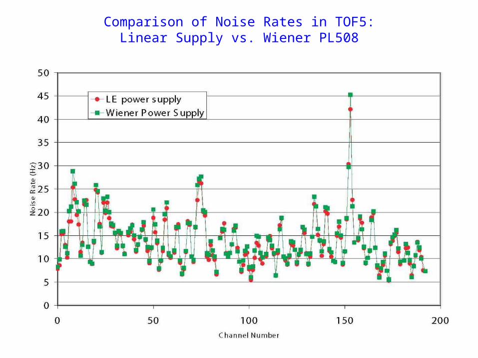
Comparison of Noise Rates in TOF5:Linear Supply vs. Wiener PL508
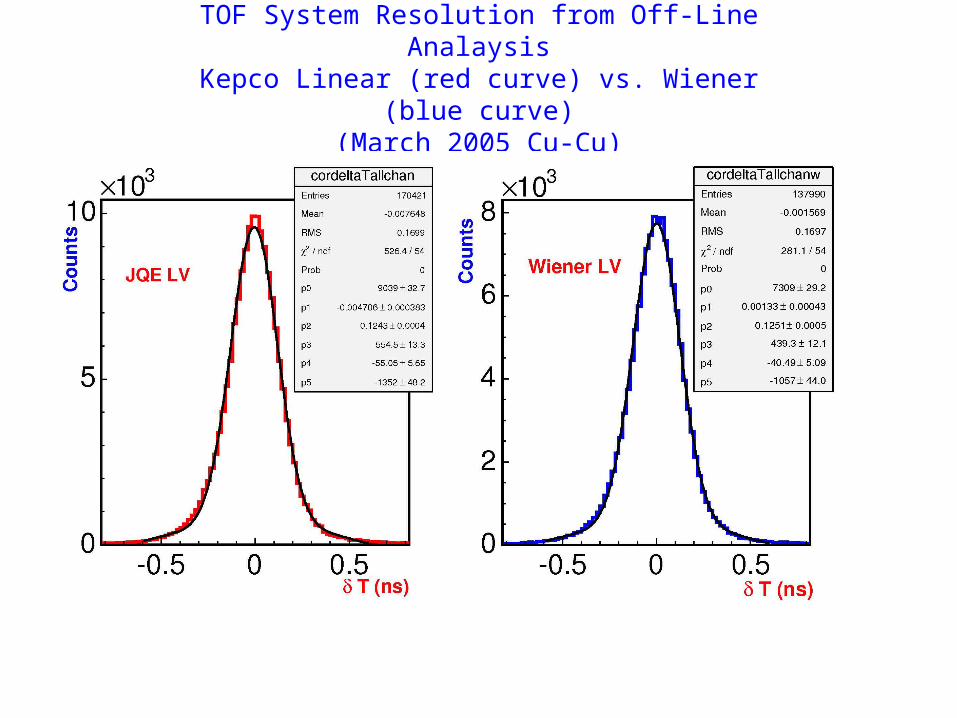
TOF System Resolution from Off-Line AnalaysisKepco Linear (red curve) vs. Wiener (blue curve)
(March 2005 Cu-Cu)
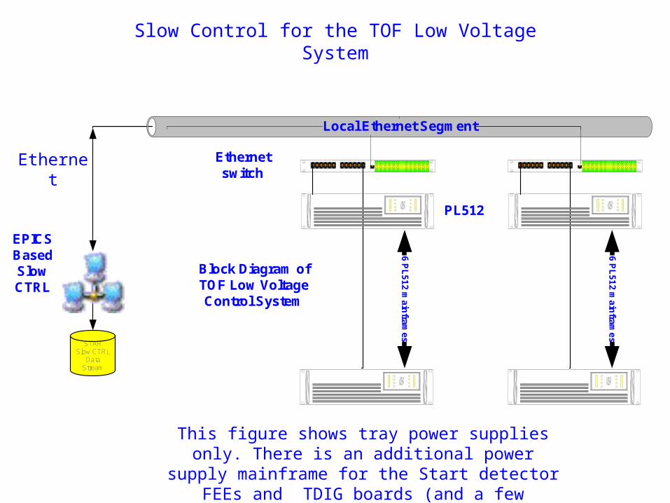
Slow Control for the TOF Low Voltage System
Block Diagram of TOF Low Voltage Control System
STARSlow CTRL
Data Stream
PL512
6 PL
512 main
frames
6 PL
512 main
frames
Local Ethernet Segment
EPICSBasedSlow CTRL
Ethernet switch
This figure shows tray power supplies only. There is an additional power supply mainframe for the Start
detector FEEs and TDIG boards (and a few spares).
Ethernet
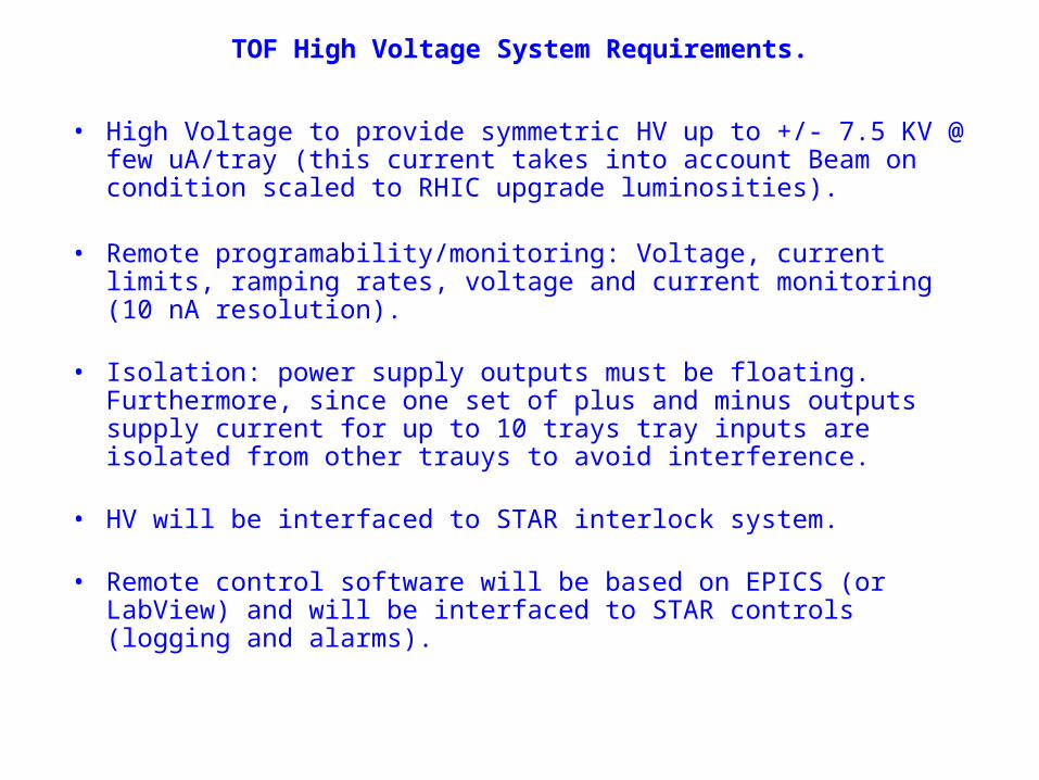
TOF High Voltage System Requirements.
• High Voltage to provide symmetric HV up to +/- 7.5 KV @ few uA/tray (this current takes into account Beam on condition scaled to RHIC upgrade luminosities).
• Remote programability/monitoring: Voltage, current limits, ramping rates, voltage and current monitoring (10 nA resolution).
• Isolation: power supply outputs must be floating. Furthermore, since one set of plus and minus outputs supply current for up to 10 trays tray inputs are isolated from other trauys to avoid interference.
• HV will be interfaced to STAR interlock system.
• Remote control software will be based on EPICS (or LabView) and will be interfaced to STAR controls (logging and alarms).
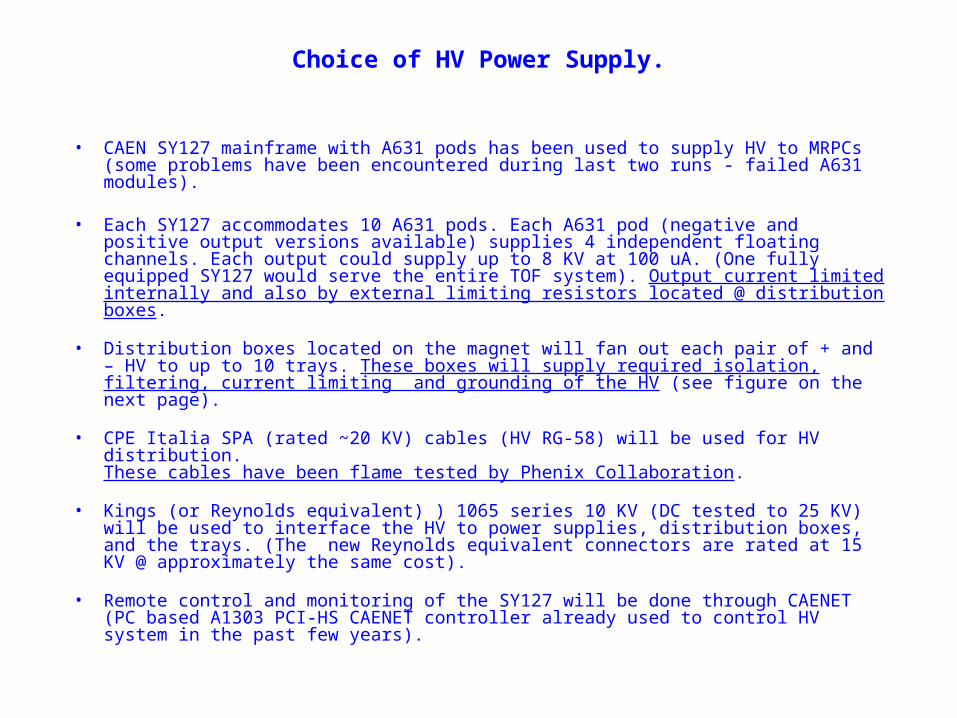
Choice of HV Power Supply.
• CAEN SY127 mainframe with A631 pods has been used to supply HV to MRPCs (some problems have been encountered during last two runs - failed A631 modules).
• Each SY127 accommodates 10 A631 pods. Each A631 pod (negative and positive output versions available) supplies 4 independent floating channels. Each output could supply up to 8 KV at 100 uA. (One fully equipped SY127 would serve the entire TOF system). Output current limited internally and also by external limiting resistors located @ distribution boxes.
• Distribution boxes located on the magnet will fan out each pair of + and – HV to up to 10 trays. These boxes will supply required isolation, filtering, current limiting and grounding of the HV (see figure on the next page).
• CPE Italia SPA (rated ~20 KV) cables (HV RG-58) will be used for HV distribution.These cables have been flame tested by Phenix Collaboration.
• Kings (or Reynolds equivalent) ) 1065 series 10 KV (DC tested to 25 KV) will be used to interface the HV to power supplies, distribution boxes, and the trays. (The new Reynolds equivalent connectors are rated at 15 KV @ approximately the same cost).
• Remote control and monitoring of the SY127 will be done through CAENET (PC based A1303 PCI-HS CAENET controller already used to control HV system in the past few years).
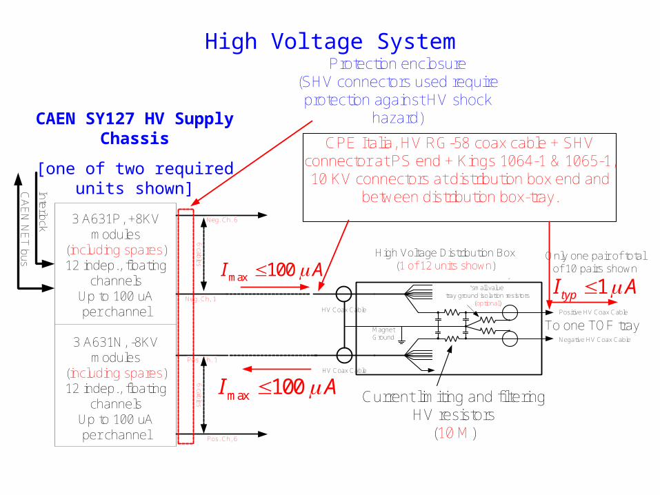
High Voltage System
Neg. Ch. 6
Neg. Ch, 1
6 ca
bles
3 A631P, +8KV modules
(including spares)12 indep., floating
channels Up to 100 uAper channel
3 A631N, -8KV modules
(including spares)12 indep., floating
channels Up to 100 uAper channel
Pos. Ch. 1
Pos. Ch, 6
6 ca
bles
HV Coax Cable
HV Coax Cable
Interlock
CA
EN
NE
T bus
Magnet Ground
Positive HV Coax Cable
Negative HV Coax Cable
High Voltage Distribution Box(1 of 12 units shown)
Only one pair of total of 10 pairs shown
To one TOF tray
“small value” tray ground isolation resistors
(optional)
Current limiting and filtering HV resistors
(10 M)
1typI Amax 100I A
max 100I A
CPE Italia, HV RG-58 coax cable + SHV connector at PS end + Kings 1064-1 & 1065-1, 10 KV connectors at distribution box end and
between distribution box-tray.
Protection enclosure(SHV connectors used require protection against HV shock
hazard)CAEN SY127 HV Supply Chassis
[one of two required units shown]
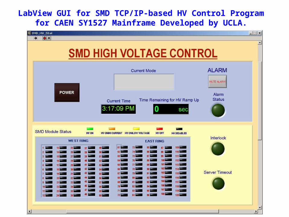
LabView GUI for SMD TCP/IP-based HV Control Program for CAEN SY1527 Mainframe Developed by UCLA.

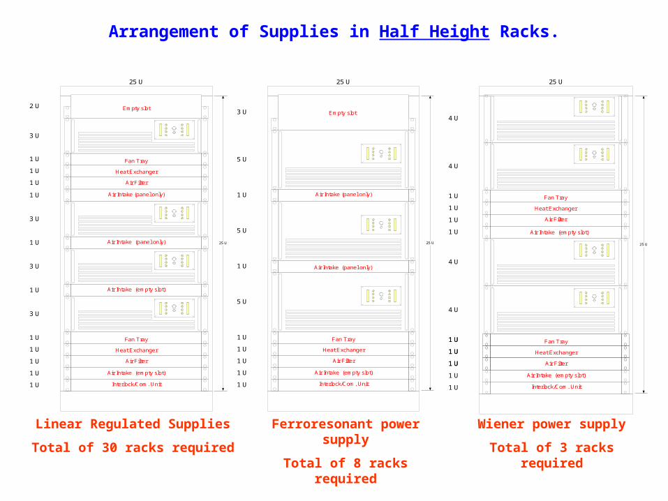
Arrangement of Supplies in Half Height Racks.
25 U
1 U
3 U
3 U
1 U
1 U
3 U
3 U
1 U Interlock/Com. Unit
Air Intake (empty slot)
Air Intake (panel only) 25 U
2 U
Air Intake (empty slot)
1 U
1 U
1 U
Air Filter
Heat Exchanger
Fan Tray
1 U
1 U
1 U
Air Filter
Heat Exchanger
Fan Tray
Empty slot
1 U Air Intake (panel only)
25 U
1 U
5 U
1 U
5 U
5 U
1 U Interlock/Com. Unit
Air Intake (empty slot)
Air Intake (panel only)
25 U
3 U
1 U
1 U
1 U
Air Filter
Heat Exchanger
Fan Tray
Empty slot
1 U Air Intake (panel only)
Linear Regulated Supplies
Total of 30 racks required
Ferroresonant power supply
Total of 8 racks required
25 U
1 U
4 U
4 U
4 U
1 U Interlock/Com. Unit
Air Intake (empty slot)
25 U
1 U
1 U
1 U
Air Filter
Heat Exchanger
Fan Tray
4 U
1 U
1 U
1 U
Air Filter
Heat Exchanger
Fan Tray
1 U
1 U
1 U
1 U Air Intake (empty slot)
Wiener power supply
Total of 3 racks required