Embed Size (px)
Citation preview

Low-Voltage Power Distribution and Electrical Installation TechnologyAnswers for infrastructure.
Communication and expansion modules
Modbus RTU communication module
Manual • 02/2011

___________________Modbus RTU communication module
___________________
___________________
___________________
Introduction 1
Modbus module 2
Modbus master 3
Low-voltage power distribution and electrical installation engineering
Modbus protocol 4Communication and expansion modules Modbus RTU communication module Manual
02/2011 3ZW1012-0KT10-0AC0

Legal information
Legal information Warning notice system
This manual contains notices you have to observe in order to ensure your personal safety, as well as to prevent damage to property. The notices referring to your personal safety are highlighted in the manual by a safety alert symbol, notices referring only to property damage have no safety alert symbol. These notices shown below are graded according to the degree of danger.
DANGER indicates that death or severe personal injury will result if proper precautions are not taken.
WARNING indicates that death or severe personal injury may result if proper precautions are not taken.
CAUTION with a safety alert symbol, indicates that minor personal injury can result if proper precautions are not taken.
CAUTION without a safety alert symbol, indicates that property damage can result if proper precautions are not taken.
NOTICE indicates that an unintended result or situation can occur if the relevant information is not taken into account.
If more than one degree of danger is present, the warning notice representing the highest degree of danger will be used. A notice warning of injury to persons with a safety alert symbol may also include a warning relating to property damage.
Qualified Personnel The product/system described in this documentation may be operated only by personnel qualified for the specific task in accordance with the relevant documentation, in particular its warning notices and safety instructions. Qualified personnel are those who, based on their training and experience, are capable of identifying risks and avoiding potential hazards when working with these products/systems.
Proper use of Siemens products Note the following:
WARNING Siemens products may only be used for the applications described in the catalog and in the relevant technical documentation. If products and components from other manufacturers are used, these must be recommended or approved by Siemens. Proper transport, storage, installation, assembly, commissioning, operation and maintenance are required to ensure that the products operate safely and without any problems. The permissible ambient conditions must be complied with. The information in the relevant documentation must be observed.
Trademarks All names identified by ® are registered trademarks of Siemens AG. The remaining trademarks in this publication may be trademarks whose use by third parties for their own purposes could violate the rights of the owner.
Disclaimer of Liability We have reviewed the contents of this publication to ensure consistency with the hardware and software described. Since variance cannot be precluded entirely, we cannot guarantee full consistency. However, the information in this publication is reviewed regularly and any necessary corrections are included in subsequent editions.
Siemens AG 3ZW1012-0KT10-0AC0 Copyright © Siemens AG 2011. Industry Sector Ⓟ 02/2012 Technical data subject to change All rights reserved Postfach 48 48 90026 NÜRNBERG GERMANY

Table of contents
1 Introduction................................................................................................................................................ 5
1.1 Purpose of this document ..............................................................................................................5
1.2 Further documentation...................................................................................................................5
1.3 Download address for software and documentation .....................................................................5
2 Modbus module ......................................................................................................................................... 7
2.1 Safety notes ...................................................................................................................................7
2.2 Device view....................................................................................................................................8
2.3 Description .....................................................................................................................................9 2.3.1 Function .........................................................................................................................................9 2.3.2 Networking of the Modbus RTU communication module ..............................................................9 2.3.3 Communication status ...................................................................................................................9 2.3.4 Transferable variables ...................................................................................................................9 2.3.5 Factory settings............................................................................................................................10
2.4 Installation....................................................................................................................................10
2.5 Connecting...................................................................................................................................10
2.6 Dimension drawings.....................................................................................................................12
3 Modbus master ........................................................................................................................................ 15
3.1 Overview ......................................................................................................................................15 3.1.1 Function .......................................................................................................................................15 3.1.2 Hardware requirements ...............................................................................................................15 3.1.3 Software requirements.................................................................................................................15
3.2 Commissioning.............................................................................................................................16
4 Modbus protocol ...................................................................................................................................... 19
4.1 General information .....................................................................................................................19 4.1.1 System architecture .....................................................................................................................19 4.1.2 Defaults ........................................................................................................................................19
4.2 Function codes.............................................................................................................................20
4.3 Register........................................................................................................................................23 4.3.1 Structure of the register ...............................................................................................................23 4.3.2 Register overview ........................................................................................................................24 4.3.3 General registers .........................................................................................................................26 4.3.4 Configuration registers.................................................................................................................27 4.3.5 Measured value registers.............................................................................................................28 4.3.5.1 Measured value registers.............................................................................................................28 4.3.5.2 Decoding of float measured values (in accordance with IEEE 754:2008)...................................30 4.3.5.3 Decoding of integer measured values .........................................................................................31
Index........................................................................................................................................................ 33
Modbus RTU communication module Manual, 02/2011, 3ZW1012-0KT10-0AC0 3

Table of contents
Modbus RTU communication module 4 Manual, 02/2011, 3ZW1012-0KT10-0AC0

Introduction 11.1 Purpose of this document
Purpose This manual describes the Modbus RTU communication module, the RS-485 Modbus master software, and the Modbus protocol.
Target group This manual is intended for planners, operators, commissioning engineers, and service and maintenance personnel.
Required basic knowledge A general knowledge of the field of electrical engineering is required to understand this manual.
Knowledge of the relevant safety regulations and standards is required for installing and connecting the device.
1.2 Further documentation You can find further details in the following documents:
● Modbus RTU/ASCII Communication Module Operating Instructions
1.3 Download address for software and documentation Download address (www.siemens.com/lowvoltage/communication-module)
Modbus RTU communication module Manual, 02/2011, 3ZW1012-0KT10-0AC0 5

Introduction 1.3 Download address for software and documentation
Modbus RTU communication module 6 Manual, 02/2011, 3ZW1012-0KT10-0AC0

Modbus module 22.1 Safety notes
DANGER
Hazardous Voltage
Will cause death, serious injury or considerable property damage.
Observe the safety instructions on the device as well as those in the operating instructions and manual.
The device may only be installed and commissioned by an approved electrical engineer.
The applicable safety and accident prevention regulations must be observed.
The device must not be opened.
When planning and installing electrical systems, always ensure adherence to the pertinent directives, regulations and provisions of the respective country.
Modbus RTU communication module Manual, 02/2011, 3ZW1012-0KT10-0AC0 7

Modbus module 2.2 Device view
Modbus RTU communication module 8 Manual, 02/2011, 3ZW1012-0KT10-0AC0
2.2 Device view
Figure 2-1 Modbus RTU communication module

Modbus module 2.3 Description
Modbus RTU communication module Manual, 02/2011, 3ZW1012-0KT10-0AC0 9
2.3 Description
2.3.1 Function The energy registers and parameters of a measuring device can be read out with the Modbus RTU communication module.
2.3.2 Networking of the Modbus RTU communication module The following diagram shows an example of the use of the Modbus RTU communication module.
The minimum configuration consists of a counter, a communication module, and a master (with an RS-232/RS-485 converter if applicable).
Figure 2-2 Modbus networking
2.3.3 Communication status A green LED indicates the status of the communication:
LED signal Status LED flashes No communication LED lights up permanently Communication active
2.3.4 Transferable variables The transferable measured variables can be found in the description of the Modbus protocol, SectionMeasured value registers (Page 28).

Modbus module 2.4 Installation
Modbus RTU communication module 10 Manual, 02/2011, 3ZW1012-0KT10-0AC0
2.3.5 Factory settings A button for resetting the module to factory settings is located on top of the device.
Baud rate: 19 200 bit/s Protocol: Modbus RTU Address: 001 Parity: None Stop bits: 1 Data format: Float (binary 32 in accordance with IEEE 754:2008)
2.4 Installation The module is positioned next to the E-counter in such a way that their IrDA interfaces are exactly opposite each other.
2.5 Connecting The device is wired via
● 2 supply terminals
● 5 terminals for data transfer
Terminal Function L, N Phase and neutral conductors D+/D- Data transfer via RS-485 RT+/RT- RS-485 terminating resistor
Only connected to terminals D+/D if the module is the first or last node of the bus cable.
Shield Terminal for cable shielding

Modbus module 2.5 Connecting
Modbus RTU communication module Manual, 02/2011, 3ZW1012-0KT10-0AC0 11
Figure 2-3 Wiring
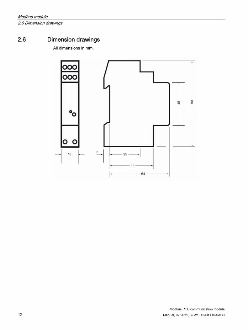
Modbus module 2.6 Dimension drawings
Modbus RTU communication module 12 Manual, 02/2011, 3ZW1012-0KT10-0AC0
2.6 Dimension drawings All dimensions in mm.

Modbus module 2.6 Dimension drawings
Modbus RTU communication module Manual, 02/2011, 3ZW1012-0KT10-0AC0 13


Modbus master 33.1 Overview
3.1.1 Function The Modbus master application enables fast configuration of the Modbus RTU communication module.
3.1.2 Hardware requirements ● Modbus RTU communication module
● Counter
● RS-232/RS-485 converter or USB/RS-485 converter
● Windows PC with Modbus master application
3.1.3 Software requirements Minimum requirements:
● Windows XP/2000
● Framework Microsoft .NET 1.1
Modbus RTU communication module Manual, 02/2011, 3ZW1012-0KT10-0AC0 15

Modbus master 3.2 Commissioning
Modbus RTU communication module 16 Manual, 02/2011, 3ZW1012-0KT10-0AC0
3.2 Commissioning
Modbus master application The Modbus master is organized into three tabs:
Tab Description Counters Management of the modules Communication Management of the COM port
Configuration of the connected Modbus RTU communication module
Settings
Resetting the energy registers
Preparation
Figure 3-1 "Communication" tab
Only one Modbus RTU communication module must be connected for configuring.
First, the "Communication" tab of the corresponding COM port must be selected.
The values must be set to the factory defaults for the initial configuration and after resetting:
19 200 bit/s, 8 data bits, no parity, 1 stop bit, Modbus RTU

Modbus master 3.2 Commissioning
Modbus RTU communication module Manual, 02/2011, 3ZW1012-0KT10-0AC0 17
Adding an interface
Figure 3-2 "Counters" tab
A new module is integrated into the Modbus network as follows:
● Open the "Counters" tab
● Click on the "New" button
● Enter a name for the module in the "Alias" field
● Enter the Modbus address
The default address for a not yet configured interface is "001"
● Click on the "Add" button
All added modules are saved in an .xml file in the application folder.
The .xml file can be exported to a freely selectable folder using the "Export" button.
An exported .xml file can be integrated again using the "Import" function.
NOTICE Changing the Modbus address on the "Counters" tab only changes the entry in the .xml file. The change is NOT transferred to the Modbus RTU communication module.

Modbus master 3.2 Commissioning
Modbus RTU communication module 18 Manual, 02/2011, 3ZW1012-0KT10-0AC0
Settings
Figure 3-3 "Settings" tab
The parameters of the Modbus RTU communication module can be configured on the "Settings" tab.
The following are available for selection:
● Transfer mode: Modbus RTU/ASCII
● Baud rate: 1 200 … 38 400 bit/s
● Modbus address of the communication module: 001 … 247
● Parity: None, even, odd
● Stop bits: 1, 2
● Read-out format: Float (binary 32 in accordance with IEEE 754:2008) or integer (64 bits)
Resetting counters On the "Settings" tab, the energy registers (active energy and/or reactive energy) of the connected counter can be reset (only for non-calibrated counters).

4Modbus protocol
4.1 General information
4.1.1 System architecture Use of the Modbus protocol for the Modbus communication interface 7KT1 907 is described below.
The communication modules support data transfer for Modbus RTU and Modbus ASCII.
4.1.2 Defaults The default settings are:
Report Modbus RTU Modbus address 001 Baud rate 19 200 bit/s Parity None Stop bits 1 Communication Float (binary 32 in accordance with IEEE
754:2008)
Modbus RTU communication module Manual, 02/2011, 3ZW1012-0KT10-0AC0 19

Modbus protocol 4.2 Function codes
Modbus RTU communication module 20 Manual, 02/2011, 3ZW1012-0KT10-0AC0
4.2 Function codes
Function codes The interface supports the Modbus function codes 03 (Read holding registers) and 06 (write single register).
Reading out registers (function code 03) This function code is used for reading out a register block. The start register and the number of registers to be read out are specified in the message frame.
Note Due to the finite length of the Modbus message frame, several requests are required to read out all registers.
The start address and the number of registers to be read out must be adapted accordingly:
Example: Poll No. 1 Start address 4099 Number of registers to be read out 100 Poll No. 2 Start address 4197 Number of registers to be read out 100 Poll No. 3 Start address 4297 Number of registers to be read out 10
Request message frame
ADR 0x03 STh STl NRh NRl CRCh CRCl
ADR Modbus address 1 … 247 (0x01 … 0XF7) 0x03 Function code for reading out STh Start address (high byte) STl Start address (low byte) NRh Number of registers to be read out (high byte) NRl Number of registers to be read out (low byte) CRCh Checksum Modbus CRC 16 Modbus (high byte) CRCl Checksum Modbus CRC 16 Modbus (low byte)
Example (hex): 02 03 10 17 00 64 F0 D6
Address: 0x02 = Device address 2
Function code: 0x03 = read
Start address: 0x1017 = Register 4119dec
Number of registers to be read out: 0x0064 = 100dec
CRC 16: 0xF0D6 = checksum for the message frame

Modbus protocol 4.2 Function codes
Modbus RTU communication module Manual, 02/2011, 3ZW1012-0KT10-0AC0 21
Reply message frame
ADR 0x03 BC RegCont CRCh CRCl
ADR Modbus address 1 … 247 (0x01 … 0xF7) 0x03 Function code for reading out BC Byte count (number of user data bytes) RegCont Register contents (data) CRCh Checksum Modbus CRC 16 Modbus (high byte) CRCl Checksum Modbus CRC 16 Modbus (low byte)
Writing to a register (function code 06) This function code is used for writing to individual registers. The address of the register to be written to and the value to be written are specified in the message frame.
If transferred correctly, the slave supplies the request message frame as the reply (echo).
Request message frame
ADR 0x06 RAh RAl RVh RVl CRCh CRCl
ADR Modbus address 1 … 247 (0x01 … 0xF7) 0x06 Function code "Writing to a register" RAh Register address (high byte) RAl Register address (low byte) RVh Value to be written (high byte) RVl Value to be written (low byte) CRCh Checksum Modbus CRC 16 Modbus (high byte) CRCl Checksum Modbus CRC 16 Modbus (low byte)

Modbus protocol 4.2 Function codes
Modbus RTU communication module 22 Manual, 02/2011, 3ZW1012-0KT10-0AC0
Example: Changing the data format from float (binary32 – default) to integer in the slave with Modbus address 1
Message frame master: 01 06 10 15 00 01 5D 0E
Modbus device address: 0x01 = Device address 1
Function code: 0x06 = Write
Register to be written to: 0x1015 = Register 4117dec
Value to be written: 0x0001 = 1dec (read-out to "Int" - see table in Sect. Configuration registers (Page 27))
CRC 16: 0x5D0E = Checksum for the message frame
Reply message frame slave (if transfer correct): 01 06 10 15 00 01 5D 0E
Note Before the change to the configuration(s) takes effect, a "Verify" message frame must be sent.
To do this, register 4116dec must be set to "1". The corresponding message frame in this example is as follows:
01 06 10 14 00 01 0C CE
Here too, the slave returns the request frame if the transfer was successful:
01 06 10 14 00 01 0C CE

Modbus protocol 4.3 Register
Modbus RTU communication module Manual, 02/2011, 3ZW1012-0KT10-0AC0 23
4.3 Register
4.3.1 Structure of the register The configuration parameters and the measured values are saved in registers (1 register = 2 bytes) in the modules. The values are transferred in "big-endian" format, i.e. the high byte is sent first, and then the low byte. Since the measured values of the counters are stored in either 2 or 4 registers, data reconstruction must be on a cross-register basis:
Example 1:Integer format of the active energy L1, T1, _import | 8 bytes | register 4119 … 4122
Example 2: Integer format of the active power L1 | 4 bytes | register 4151 … 4152
Whether a measured value is stored in 2 or 4 registers depends on the one hand on the measured value itself and, on the other, on the data type. It is possible to save and transfer the values in float (default) or integer format.
In float format, the data is always stored in 2 registers (binary 32 in accordance with IEEE 754:2008), and in integer format, it depends on the measured value (see table in Sect. Measured value registers (Page 28)).

Modbus protocol 4.3 Register
Modbus RTU communication module 24 Manual, 02/2011, 3ZW1012-0KT10-0AC0
4.3.2 Register overview Register Counter type
Dec Hex
Description
3-phase Single-phase
Notes
4099 0x1003 Device type x x 4100 0x1004 Firmware version x x 4101 0x1005 Overflow alarm x x 4102 0x1006 Power tariff x x 4104 0x1008 PID (product identification) bytes 1 and 2 x x 4105 0x1009 PID – Bytes 3 and 4 x x 4106 0x100A PID – Bytes 5 and 6 x x 4107 0x100B PID – Bytes 7 and 8 x x 4108 0x100C PID – Bytes 9 and 10 x x 4109 0x100D PID – Bytes 11 and 12 x x 4110 0x100E PID – Bytes 13 and 14 x x
General registers (function code 03) Sect. General registers (Page 26)
4111 0x100F Protocol type x x 4112 0x1010 Data transfer rate x x 4113 0x1011 Parity x x 4114 0x1012 Stop bits x x 4115 0x1013 Modbus address x x 4116 0x1014 Control command interface resetting x x 4117 0x1015 Data format x x 4118 0x1016 Control command reset energy counter x x
Configuration registers (function code 06) Sect. Configuration registers (Page 27)
4119 0x1017 Active energy L1, T1, _import (kWh) x x 4123 0x101B Active energy L2, T1, _import (kWh) x 4127 0x101F Active energy L3, T1, _import (kWh) x 4131 0x1023 Active energy Σ T1, _import (kWh) x 4135 0x1027 Active energy L1, T2, _import (kWh) x x 4139 0x102B Active energy L2, T2, _import (kWh) x 4143 0x102F Active energy L3, T2, _import (kWh) x 4147 0x1033 Active energy Σ T2, _import (kWh) x 4151 0x1037 Active power L1 (kW) x x 4153 0x1039 Active power L2 (kW) x 4155 0x103B Active power L3 (kW) x 4157 0x103D Active power Σ (kW) x 4161 0x1041 Active energy L1, T1, _export (kWh) x x 4165 0x1045 Active energy L2, T1, _export (kWh) x 4169 0x1049 Active energy L3, T1, _export (kWh) x 4173 0x104D Active energy Σ T1, _export (kWh) x 4177 0x1051 Active energy L1, T2, _export (kWh) x x 4181 0x1055 Active energy L2, T2, _export (kWh) x 4185 0x1059 Active energy L3, T2, _export (kWh) x
Measured value registers (function code 03) Sect. Measured value registers (Page 28)

Modbus protocol 4.3 Register
Modbus RTU communication module Manual, 02/2011, 3ZW1012-0KT10-0AC0 25
Register Counter type
Dec Hex Single-phase
Description
3-phase
Notes
4189 0x105D Active energy Σ T2, _export (kWh) x 4193 0x1061 Reactive energy L1, T1, _import (kvarh) x x 4197 0x1065 Reactive energy L2, T1, _import (kvarh) x 4201 0x1069 Reactive energy L3, T1, _import (kvarh) x 4205 0x106D Reactive energy Σ T1, _import (kvarh) x 4209 0x1071 Reactive energy L1, T2, _import (kvarh) x x 4213 0x1075 Reactive energy L2, T2, _import (kvarh) x 4217 0x1079 Reactive energy L3, T2, _import (kvarh) x 4221 0x107D Reactive energy Σ T2, _import (kvarh) x 4225 0x1081 Reactive energy L1, T1, _export (kvarh) x x 4229 0x1085 Reactive energy L2, T1, _export (kvarh) x 4233 0x1089 Reactive energy L3, T1, _export (kvarh) x 4237 0x108D Reactive energy Σ T1, _export (kvarh) x 4241 0x1091 Reactive energy L1, T2, _export (kvarh) x x 4245 0x1095 Reactive energy L2, T2, _export (kvarh) x 4249 0x1099 Reactive energy L3, T2, _export (kvarh) x 4253 0x109D Reactive energy Σ T2, _export (kvarh) x 4257 0x10A1 Reactive power L1 (kvar) x x 4259 0x10A3 Reactive power L2 (kvar) x 4261 0x10A5 Reactive power L3 (kvar) x 4263 0x10A7 Reactive power Σ (kvar) x 4267 0x10AB Voltage L1-N (V) x x 4269 0x10AD Voltage L2-N (V) x 4271 0x10AF Voltage L3-N (V) x 4273 0x10B1 Voltage L1-L2 (V) x 4275 0x10B3 Voltage L2-L3 (V) x 4277 0x10B5 Voltage L3-L1 (V) x 4279 0x10B7 Current L1 (A) x x 4281 0x10B9 Current L2 (A) x 4283 0x10BA Current L3 (A) x 4285 0x10BD Apparent power L1 (kVA) x x 4287 0x10BF Apparent power L2 (kVA) x 4289 0x10C1 Apparent power L3 (kVA) x 4291 0x10C3 Apparent power Σ (kVA) x 4295 0x10C7 Power factor cos φ L1 x x 4297 0x10C9 Power factor cos φ L2 x 4299 0x10CB Power factor cos φ L3 x 4301 0x10CD Power factor cos φ Σ x 4303 0x10CF Frequency (Hz) x x

Modbus protocol 4.3 Register
Modbus RTU communication module 26 Manual, 02/2011, 3ZW1012-0KT10-0AC0
4.3.3 General registers Register (dec) Designation Description
Code for communication monitoring 4099 Device type 0dec 1dec 3dec
No IR communication with the counter counter 3-phase counter 1-phase
4100 Firmware version Firmware version, version of the interface This register adopts a value other than zero if the counter detects voltage or current values that exceed the nominal limit values. The low byte of this register is encoded as follows (see below)*) The following rules apply:
4101 Alarm overflow
OFV xOFI x n.u.
Voltage exceeded (to phase x with x є [1, 2, 3]) current exceeded (to phase x with x є [1, 2, 3]) not used
4102-03 Power tariff 0 1
Tariff 1 used Tariff 2 used
4104-10 PID Character string for product identification (max. 14 bytes)
*) 4101 alarm overflow. The low byte of this register is encoded as follows:
n.u. n.u. OFV 3 OFI 3 OFV 2 OFI 2 OFV 1 OFI 1

Modbus protocol 4.3 Register
Modbus RTU communication module Manual, 02/2011, 3ZW1012-0KT10-0AC0 27
4.3.4 Configuration registers These registers are used for configuring the interface and for resetting the energy values of the counter (only possible with non-MID-counters).
Note For the configuration changes to become effective, register 4116 must be set to "1" at the end.
This does not apply for register 4118. The changes are applied immediately here.
Register (dec) Designation Description
0dec Modbus protocol RTU 4111 Protocol type 1dec Modbus protocol ASCII The following data transfer rates are available: 1.200 0x04B0 2.400 0x0960 4.800 0x12C0 9.600 0x2580 19.200 0x4B00
4112 Baud rate
38.400 0x9600 0dec None 1dec Even
4113 Parity
2dec Odd 4114 Stop bits 1 or 2 4115 Modbus address 1 – 247dec (0x0001 … 0x00F7)
0dec All modifications ineffective 4116 Interface resetting 1dec All modifications effective
0dec Measured variables encoded as 32-bit float values (see Sect. Decoding of float measured values (in accordance with IEEE 754:2008) (Page 30))
4117 Data format
1dec Measured variables encoded as integers (see Sect. Decoding of integer measured values (Page 31))
1dec Resetting the counter registers relating to the active energy 2dec Resetting the counter registers relating to the reactive energy
4118 Resetting energy counters
3dec Resetting all registers

Modbus protocol 4.3 Register
Modbus RTU communication module 28 Manual, 02/2011, 3ZW1012-0KT10-0AC0
4.3.5 Measured value registers
4.3.5.1 Measured value registers These registers contain all the measured variables the counter sends via the IR interface to the communication module.
All measured variables in the 32-bit floating-point format (IEEE 754:2008) are encoded as standard, i.e. each measured value is stored in 2 registers:
Example:"Active energy L1, T1, _import (kWh)" per register 4119 and 4120; registers 4121 and 4122 are not used here but remain reserved for integer read-out.
To obtain the integer representation, register 4117 must be set (see Sect. Configuration registers (Page 27)).
The following table applies in integer mode:
Availability depending on the connected counter type
Register dec
Definition
3-phase Single-phase
Length in bytes (Integer format)
4119 Active energy L1, T1, _import (kWh) x x 8 4123 Active energy L2, T1, _import (kWh) x 8 4127 Active energy L3, T1, _import (kWh) x 8 4131 Active energy Σ T1, _import (kWh) x 8 4135 Active energy L1, T2, _import (kWh) x x 8 4139 Active energy L2, T2, _import (kWh) x 8 4143 Active energy L3, T2, _import (kWh) x 8 4147 Active energy Σ T2, _import (kWh) x 8 4151 Active power L1 (kW) x x 4 4153 Active power L2 (kW) x 4 4155 Active power L3 (kW) x 4 4157 Active power Σ (kW) x 8 4161 Active energy L1, T1, _export (kWh) x x 8 4165 Active energy L2, T1, _export (kWh) x 8 4169 Active energy L3, T1, _export (kWh) x 8 4173 Active energy Σ T1, _export (kWh) x 8 4177 Active energy L1, T2, _export (kWh) x x 8 4181 Active energy L2, T2, _export (kWh) x 8 4185 Active energy L3, T2, _export (kWh) x 8 4189 Active energy Σ T2, _export (kWh) x 8 4193 Reactive energy L1, T1, _import (kvarh) x x 8 4197 Reactive energy L2, T1, _import (kvarh) x 8 4201 Reactive energy L3, T1, _import (kvarh) x 8 4205 Reactive energy Σ T1, _import (kvarh) x 8 4209 Reactive energy L1, T2, _import (kvarh) x x 8 4213 Reactive energy L2, T2, _import (kvarh) x 8

Modbus protocol 4.3 Register
Modbus RTU communication module Manual, 02/2011, 3ZW1012-0KT10-0AC0 29
Availability depending on the connected counter type
Register dec
Definition
3-phase (Integer format)
Single-phase
Length in bytes
4217 Reactive energy L3, T2, _import (kvarh) x 8 4221 Reactive energy Σ T2, _import (kvarh) x 8 4225 Reactive energy L1, T1, _export (kvarh) x x 8 4229 Reactive energy L2, T1, _export (kvarh) x 8 4233 Reactive energy L3, T1, _export (kvarh) x 8 4237 Reactive energy Σ T1, _export (kvarh) x 8 4241 Reactive energy L1, T2, _export (kvarh) x x 8 4245 Reactive energy L2, T2, _export (kvarh) x 8 4249 Reactive energy L3, T2, _export (kvarh) x 8 4253 Reactive energy Σ T2, _export (kvarh) x 8 4257 Reactive power L1 (kvar) x x 4 4259 Reactive power L2 (kvar) x 4 4261 Reactive power L3 (kvar) x 4 4263 Reactive power Σ (kvar) x 8 4267 Voltage L1-N (V) x x 4 4269 Voltage L2-N (V) x 4 4271 Voltage L3-N (V) x 4 4273 Voltage L1-L2 (V) x 4 4275 Voltage L2-L3 (V) x 4 4277 Voltage L3-L1 (V) x 4 4279 Current L1 (A) x x 4 4281 Current L2 (A) x 4 4283 Current L3 (A) x 4 4285 Apparent power L1 (kVA) x x 4 4287 Apparent power L2 (kVA) x 4 4289 Apparent power L3 (kVA) x 4 4291 Apparent power Σ (kVA) x 8 4295 Power factor cos φ L1 x x 4 4297 Power factor cos φ L2 x 4 4299 Power factor cos φ L3 x 4 4301 Power factor cos φ Σ x 4 4303 Frequency (Hz) x x 4
Abbreviations: T1/T2 stands for tariff 1 and tariff 2. The symbol Σ represents the total (over all three phases) Export/import: Indicates whether the energy is generated (exported) or consumed (imported).

Modbus protocol 4.3 Register
Modbus RTU communication module 30 Manual, 02/2011, 3ZW1012-0KT10-0AC0
4.3.5.2 Decoding of float measured values (in accordance with IEEE 754:2008) Data reconstruction is regulated in IEEE 754:2008. Below is just a brief example:
Example: Active energy L1, T1, _import, 4 bytes (2 registers)
The active energy L1, T1, _import is encoded in registers 4119 and 4120 (4121 and 4122 are not used in float mode).
Measured value:
Sign:
Exponent:
Mantissa

Modbus protocol 4.3 Register
Modbus RTU communication module Manual, 02/2011, 3ZW1012-0KT10-0AC0 31
4.3.5.3 Decoding of integer measured values The following rule has been defined for the reconstruction of the data transferred in integer mode:
Measured values encoded in 4 bytes (2 registers)
The values saved in these registers must be divided by 10 000dec to reconstruct the original value.
Example: Active power L1 (kW)
The active power for phase L1 is encoded in registers 4151 and 4152 (cf. table in Sect. Register overview (Page 24))
Byte A: 0x00 Byte B: 0x01 Byte C: 0xDE Byte D: 0x4F
Transferred value: 0x001DE4F
Integer value (unsigned): 122.447dec
Measured value:

Modbus protocol 4.3 Register
Modbus RTU communication module 32 Manual, 02/2011, 3ZW1012-0KT10-0AC0
Measured values encoded in 8 bytes (4 registers)
In this case, reconfiguration of the original value is a bit more complicated:
The int value encoded in the upper 4 bytes must be multiplied by 109 (1 000 000 000dec).
The value of the lower 4 bytes must be added to this result.
The resulting value must then be divided by 10 000dec to obtain the measured value.
Example: Active energy L1, T1, _import
The active energy L1, T1, _import is encoded in registers 4119 … 4122.
Transferred data stream (hex): 00 00 00 04 12 98 E9 C4
Byte A: 0x00 Byte E: 0x12 Byte B: 0x00 Byte F: 0x98 Byte C: 0x00 Byte G: 0xE9 Byte D: 0x04 Byte H: 0xC4
Upper 4 bytes (upper double word): 0x00000004 = 4dec , ×109 → 4 000 000 000dec
Lower 4 bytes (lower double word): 0x1298E9C4 = 312 011 204dec
Integer value (unsigned): 4 000 000 000dec + 312 011 204dec = 4 312 011 204dec
Measured value:

Index
C
Communication status, 9 Connecting, 10
D
Device view, 8 Dimension drawing, 12
F
Factory settings, 10
I Installation, 10
L
LED, 9
M
Minimum configuration, 9 Modbus master application
Add interface, 17 Communication, 16 Counters, 17 Function, 15 Hardware requirements, 15 Reset counters, 18 Settings, 18 Software requirements, 15
Modbus protocol Decoding of float measured values, 30 Decoding of integer measured values, 31 Default settings, 19 Function codes, 20 Register, overview, 24 Registers, configuration, 27 Registers, measured variables, 28 Registers, resetting the energy values, 27
Registers, structure, 23 More information, 5
N
Networking, 9
R
Required basic knowledge, 5
S
Safety instructions, 7
T
Transferable variables, 28
V
Variables, non-transferable, 28
W
Wiring, 10
Modbus RTU communication module Manual, 02/2011, 3ZW1012-0KT10-0AC0 33

Index
Modbus RTU communication module 34 Manual, 02/2011, 3ZW1012-0KT10-0AC0

www.siemens.com/lowvoltage
Subject to change without prior noticeOrder No.: 3ZW1012-0KT10-0AC0 © Siemens AG 2011
Siemens AGInfrastructure & Cities SectorLow and Medium Voltage DivisionLow Voltage DistributionPostfach 10 09 5393009 RegensburgGERMANY
Service & Support
Download catalogs and information material:www.siemens.com/lowvoltage/infomaterial
Newsletter – always up to date:www.siemens.com/lowvoltage/newsletter
E-business in the Industry Mall:www.siemens.com/lowvoltage/mall
Online Support:www.siemens.com/lowvoltage/support
Contact for all technical information: Technical Support www.siemens.com/lowvoltage/technical-support