Embed Size (px)
Citation preview

Coordinated by Communication avec la clientèle for vice-présidence – Réseau de distribution
Low-Voltage Electrical ServiceStandard E.21-10
10th EditionJune 2014
L


Low-Voltage Electrical Service Standard E.21-10
10th Edition June 2014

© Hydro-Québec, June 2014All rights reserved. Reproduction authorized only for educational purposes, with acknowledgment of source.

1
Table des matières
Introduction 7
0 General Information 90.1 Application 90.2 Units of measure 100.3 Definitions 11
1 Administrative and Technical Information 171.1 Administrative information 17
1.1.1 Demande d’alimentation et déclaration de travaux form 171.1.2 Charges 181.1.3 Responsibilities of the master electrician 18
1.2 Technical information 221.2.1 General 221.2.2 Available voltages and limits on supply from power line 261.2.3 Supply over one or more distribution service loops 281.2.4 Metering equipment 29
2 Overhead Service 312.1 Number of service entrances per building 31
2.1.1 New service entrance 312.1.2 Service entrance modifications 312.1.3 Total load and conductor size 31
2.2 Spool rack 312.2.1 Supply and installation 312.2.2 Location 322.2.3 Clearances 322.2.4 Distance between spool rack and service head 322.2.5 Common spool rack 332.2.6 Distance between two spool racks 332.2.7 Mechanical strength 332.2.8 Height of spool rack 332.2.9 Conductor clearance above roofs 342.2.10 Distance between spool rack and
telecommunications wires 342.2.11 Ice fenders above conductors 342.2.12 Common support 35

2
2.3 Service entrance 352.3.1 Length of conductors at service head 352.3.2 Service mast 352.3.3 Length of service mast 362.3.4 Metal conduit with PVC section 362.3.5 Insulation of neutral conductor 36
2.4 Service entrance modification 362.4.1 One connection point 362.4.2 More than one connection point 362.4.3 Service entrances on existing rooftop support structures 372.4.4 Reconnection by a master electrician 37
2.5 Service loop 392.5.1 Supply and installation 392.5.2 Clearance 39
2.6 Service loop provided by customer 392.6.1 Supply and installation 392.6.2 Conditions 39
2.7 Connection point 402.7.1 Access to connection point 402.7.2 Location 412.7.3 Clearance around parts of a building 422.7.4 Connectors 43
2.8 Overhead-underground service entrance 432.8.1 Technical requirements 452.8.2 Connection point 46
2.9 Connection of equipment 462.9.1 Technical requirements 472.9.2 Connection point 47
3 Underground Service 493.1 Service entrance 49
3.1.1 Individual meter socket 493.1.2 Multiple-meter mounting device 493.1.3 Junction box 493.1.4 Connection box for flat-rate service 49
3.2 Connection point 503.2.1 In the meter socket 503.2.2 In the multiple-meter mounting device 503.2.3 In the junction box 503.2.4 In the connection box for flat-rate service 513.2.5 In the customer structure 51

3
3.3 Underground conduit system 513.4 Conduits 51
3.4.1 Description 513.4.2 Conduit entrance 513.4.3 Conduit compatibility 523.4.4 Riser conduit on an exterior wall 523.4.5 Expansion joint and adapter 523.4.6 Inspection and cleaning 523.4.7 Cable-pulling rope 533.4.8 Conduit sealing 533.4.9 Repair of above-grade conduit systems 53
3.5 Pullbox and junction box 533.5.1 Use 533.5.2 Location of pullbox or junction box 533.5.3 Specifications 543.5.4 Supply and installation 543.5.5 Access and clearance 543.5.6 Placement of conduits 553.5.7 Buildings with no basement 553.5.8 Plan required for special cases 56
3.6 Connection box for flat-rate service 563.6.1 Use 563.6.2 Supply and installation 563.6.3 Specifications 56
3.7 Service loop 563.7.1 Supply and installation 563.7.2 Customer’s handhole 573.7.3 Customer’s manhole 573.7.4 Service loop beneath or inside a building 573.7.5 Clearances 57
3.8 Connection 583.8.1 Lugs 58
4 Temporary Service 594.1 Application 594.2 Service requirements 594.3 Overhead service 594.4 Underground service 60

4
5 Metering 635.1 Types of metering 635.2 Choice of metering equipment 635.3 120/240-V delivery point 63
5.3.1 Current rating of 200 A or less 635.3.2 Current rating of more than 320 A 63
5.4 120/208-V delivery point 635.4.1 Current rating of 200 A or less 635.4.2 Current rating of more than 200 A 63
5.5 347/600-V delivery point 645.5.1 Current rating of 200 A or less 645.5.2 Current rating of more than 200 A 64
5.6 600-V delivery point 645.7 Service entrance equipment clearances 64
5.7.1 General 645.7.2 Disconnect devices 655.7.3 Transformer enclosure 655.7.4 Combustible gas exhausts or vents 65
5.8 Grouped or outdoor metering equipment 655.8.1 Grouping of equipment for different voltages 655.8.2 Enclosures or equipment assemblies approved
for outdoor use 655.9 Equipment on supply side of metering equipment 665.10 Protection of metering equipment 675.11 Permanent platform and fixtures 675.12 Customer-owned low-voltage transformers 685.13 Fire pump 685.14 Permanent identification
of service entrance equipment 685.14.1 Identification marking 685.14.2 Methods of identification 69
5.15 Identification of service entrance conductors 695.16 Safety precautions 69
5.16.1 Padlocking 695.16.2 Zero-voltage testing 70

5
6 Self-Contained Metering 716.1 Meter socket supply and installation 716.2 Meter socket specifications 716.3 Location of meter sockets 73
6.3.1 Height of meter socket 746.4 120/240-V delivery point 74
6.4.1 Accepted meter sockets 746.4.2 Individual meter sockets and multiple-meter
mounting devices 746.4.3 Grouped supply 766.4.4 Metering centre 76
6.5 120/208-V delivery point 766.5.1 Accepted meter sockets 766.5.2 Meter socket location and installation 76
6.6 347/600-V delivery point 766.6.1 Accepted meter sockets 766.6.2 Meter socket location and installation 776.6.3 Metering centre location and installation 77
6.7 Zero-voltage testing 77
7 Metering Equipment with Transformer Enclosures 797.1 Supply and location of metering equipment 79
7.1.1 Master electrician’s responsibilities 797.1.2 Hydro-Québec’s responsibilities 79
7.2 Transformer enclosures 807.2.1 Accepted transformer enclosures 807.2.2 Transformer enclosure specifications 807.2.3 Transformer enclosure location 807.2.4 Transformer enclosure height 80
7.3 Conduits 807.3.1 Power conductor conduits 817.3.2 Conduit for metering conductors 81
7.4 Service entrance conductors 817.5 Meter 82
7.5.1 Location of single-phase meter 827.5.2 Location of three-phase meter 82
7.6 Zero-voltage testing 82

6
8 Metering Equipment with Metering Compartment 838.1 Supply and location of metering equipment 83
8.1.1 Responsibilities of the master electrician 838.1.2 Hydro-Québec’s responsibilities 84
8.2 Metering compartment 848.2.1 Applicable standards 848.2.2 Metering compartment specifications 85
8.3 Conduit from metering compartment to transformer enclosure or outdoor cabinet 86
8.4 Transformer enclosures 878.4.1 Height of transformer enclosures 87
8.5 Outdoor enclosures 878.5.1 Location of outdoor enclosures 878.5.2 Specifications of outdoor enclosure 87
8.6 Zero-voltage testing 88
Figures Tables Job Aids Index
77
Introduction The conditions governing electrical service are laid out in the document Conditions of Electricity Service as approved annually by the Régie de l’énergie.
Standard E.21-10 (this document) covers low-voltage electricity supply and is based on the document above and on the Hydro-Québec Distribution standards in effect.
It takes into account the conditions of application stipulated in the Québec Construction Code, Chapter V – Electricity (C22.10, latest edition), hereinafter the “Code”.
The following three standards are also based on the above documents:
E.21-11, Service d’électricité en basse tension à partir des postes distributeurs (low-voltage electrical service from distribution substations) – in French only;
E.21-12, Service d’électricité en moyenne tension (medium-voltage electricity service) – in French only;
F.22-01, Electricity Metering for Medium- and High-Voltage Installations.
This 10th edition of Standard E.21-10 went into effect on June 30, 2014. It is designed to provide employees, master electricians, consulting engineers and manufacturers with information on implementing or modifying low-voltage installations. It is also meant to facilitate relations between Hydro-Québec and its customers regarding such matters.
Québec regulations take precedence over this Standard in case of conflicting interpretations, and the French version takes precedence over the English version in the event of discrepancies.
Alain Sayegh, Eng. Director – System Policies and Planning Vice-présidence – Réseau de distribution Hydro-Québec Distribution
André Potvin, Eng. Director – Metering Infrastructure and Technological Solutions Hydro-Québec Distribution

88
The content has been approved by a Hydro-Québec Distribution task force and the technical content checked and validated by the engineers below:
Chapters 1, 2, 3 and 4:
Jacques Côté, Engineer
Chapters 1, 5, 6, 7 and 8:
Denis Deslauriers, Engineer Dany Généreux, Engineer
The content has also been validated by the following outside parties:
Corporation des maîtres électriciens du Québec (CMEQ)Michel Bonneau Director Direction des services techniques et SST
Imed Laouini, Eng., Ph. D. Technical Advisor Direction des services techniques et SST
Régie du bâtiment du Québec (RBQ)Gilbert Montminy, Eng. Manager, Electricity Sector Direction de la réglementation et de l’expertise conseil
Charles Pineault Technical Advisor Direction de la réglementation et de l’expertise conseil
The content has been approved by a Hydro-Québec Distribution task force and the technical content checked and validated by the engineers below:
Chapters 1, 2, 3 and 4:
Jacques Côté, Engineer
Chapters 1, 5, 6, 7 and 8:
Denis Deslauriers, Engineer Dany Généreux, Engineer
The content has also been validated by the following outside parties:
Corporation des maîtres électriciens du Québec (CMEQ)Michel Bonneau Directeur Direction des services techniques et SST
Imed Laouini, Eng., Ph.D. Conseiller techniqueDirection des services techniques et SST
Régie du bâtiment du Québec (RBQ)Gilbert Montminy, Eng. Responsable du secteur électrique Direction de la réglementation et de l’expertise conseil
Charles Pineault Conseiller technique Direction de la réglementation et de l’expertise conseil
8
The content has been approved by a Hydro-Québec Distribution task force and the technical content checked and validated by the engineers below:
Chapters 1, 2, 3 and 4:
Jacques Côté, Engineer
Chapters 1, 5, 6, 7 and 8:
Denis Deslauriers, Engineer Dany Généreux, Engineer
The content has also been validated by the following outside parties:
Corporation des maîtres électriciens du Québec (CMEQ)Michel Bonneau Director Direction des services techniques et SST
Imed Laouini, Eng., Ph. D. Technical Advisor Direction des services techniques et SST
Régie du bâtiment du Québec (RBQ)Gilbert Montminy, Eng. Manager, Electricity Sector Direction de la réglementation et de l’expertise conseil
Charles Pineault Technical Advisor Direction de la réglementation et de l’expertise conseil

9
General Information Chapter 0
0 General Information
0.1 Application The purpose of this Standard is to describe the technical characteristics and requirements applicable to low-voltage service supplied directly from a line anywhere within the territory served by Hydro-Québec Distribution. It also describes the technical characteristics and requirements for metering elec-tricity at a rated ampacity not exceeding 6,000 A. The requirements herein are applicable to new installations as well as to any modification of a customer’s service entrance.
A master electrician finding it impossible to comply with this Standard must, before carrying out work, contact a Hydro-Québec representative at 1 877 COURANT (1 877 268-7268) to agree on a solution. The list of products accepted by Hydro-Québec Distribution can be found on the Web site for master electricians (www.hydroquebec.com/cmeq). A copy can also be obtained by calling 1 800 ENERGIE (1 800 363-7443).
If no provision covers a given modification, the requirements for a new installation apply.

10
Chapter 0 General Information
0.2 Units of measureIn this Standard, the following units of measure are used:
active power kilowatt (kW)
angle degree (°)
apparent power kilovoltampere (kVA)
conductor size American wire gauge (AWG) thousand circular mils (kcmil)
force newton (N)
length metre (m) millimetre (mm)
rated ampacity ampere (A)
voltage volt (V)
Dimensions in drawings are given in millimetres unless stated otherwise.

11
General Information Chapter 0
0.3 DefinitionsThe most common terms are defined below. Other concepts explained in the reference documents referred to earlier must be considered in applying this Standard.
backup generator A stand-alone generator designed to supply emergency circuits during a power failure (called an “emergency generator” in the Conditions of Electricity Service).
Code The Québec Construction Code, Chapter V – Electricity (C22.10, latest edition).
Conditions of Electricity Service The conditions governing the provision of electrical service by Hydro-Québec, as established by the Régie de l’énergie.
connection box for flat-rate service A metal box containing the connections for supplying a customer who has a flat-rate contract with Hydro-Québec. (See Figure 3.10)
customer pole A pole that belongs to the customer and is part of the customer’s electrical installation starting at the connection point. (See Figure 0.04)
disconnect device A device, group of devices or other means for cutting off the flow of current through conductors in a circuit.
fixed grounding point A metal part with a round head, hexagonal base and threaded stem, for temporarily connecting the grounding cable. (See figures 8.02 and 8.03)
grouped supply A customer’s service entrance that supplies more than one delivery point. (See Figure 0.01)
handholeA concrete underground structure, generally circular and fairly small, used to connect a customer installation. Workers reach into but do not enter a handhole.
junction box A metal enclosure containing the connections between the underground distribution service loop cables and the service entrance conductors. (See figures 3.05 to 3.09)
load side The part of the line or electrical installation located between a given point and the load.

12
Chapter 0 General Information
master electrician A member of the Corporation des maîtres électriciens as defined in the Master Electricians Act (CQLR, c. M-3). For purposes of application of this Standard, the term also covers any holder of an owner-builder’s licence (subclass 16) from the Régie du bâtiment du Québec.
mains hum An abnormal level of noise due to mechanical vibration of the service conduit or accessories.
manhole An underground concrete civil structure, large enough for workers to enter, that is used for joining cables from one or more underground conduits.
metal-clad substation A metal enclosure with separate metal compartments housing disconnect devices, protective equipment, metering transformers, busbars and other components. (See figures 8.02 and 8.03)
meter room A room designed to house meter sockets and/or transformer enclosures and their service boxes, and complying with the provisions herein.
meter socket A device equipped with a metal housing and metal jaws into which the blades of a plug-in meter can fit. The meter socket may be single or part of a multiple-meter mounting device or metering centre.
meter support A device for installing a plug-in meter, equipped with a test-terminal block and a mechanism for affixing a seal. (See Figure 7.02)
metering centre A metal enclosure used to house a service box, protective devices or switches, and meter sockets. Each meter socket must have a mechanism for affixing a seal. (See Figure 0.01)
multiple supply An arrangement whereby several service entrances are supplied from a single connection point. (See Figure 0.02)
multiple-meter mounting device A device containing a number of meter sockets interconnected by busbars. (See Figure 0.01)
multiplex cable A cable consisting of insulated conductor strands twisted around a neutral messenger or neutral support.

13
General Information Chapter 0
overhead-underground service entrance An underground service entrance connected to an overhead power line. (See figures 2.23 to 2.25)
padlockableA term describing any device having means specifically designed for affixing a padlock, thus prevent tampering.
pole A structure supporting the conductors and other electrical hardware needed for overhead and overhead-underground distribution of low- or medium-voltage electricity. (See Figure 0.04)
pole-mounted substation A transformer substation consisting of one or more overhead transformers mounted on a pole.
power system Unless otherwise stated, the electricity distribution system as defined in the Act respecting the Régie de l’énergie.
premises A building, site or structure with an electrical installation to which Hydro-Québec can supply power.
protective device A device that protects against overcurrent by automatically tripping open an electrical circuit under specified overload or short-circuit conditions, either electromechanically or by melting a metal fuse.
pullbox An indoor metal enclosure used to pull underground distribution service loop cables to the metering equipment without splicing. (See Figure 3.03)
readily accessible location An area that can be accessed without having to step over or remove obstructions, nor use a fixed or portable ladder or any other such means. Snow is not considered an obstruction. Any passageway leading to this location must be at least 600 mm wide and 2 m high and kept clear at all times. An indoor location must have adequate lighting.
rooftop support structure A metal support structure fitted with insulators and installed on the roof of a building. (See Figure 2.14)
row house A building belonging to a row of several adjacent buildings connected to each other by common walls.

14
Chapter 0 General Information
sag In an overhead power line span, the maximum vertical distance between a conductor and a straight line between its two points of attachment. Practically, over flat terrain, sag occurs at the midpoint of the span, and is therefore called the “mid-span sag”.
saline environment 1.6-km strip of land along the shoreline or coast of any saltwater body. Saline environments include the land along the Fleuve Saint-Laurent east of the Rivière Saguenay on the north shore and east of Trois-Pistoles on the south shore, along with the Gaspé Peninsula and the Îles-de-la-Madeleine.
self-generation Power generated by a customer, by means of a facility owned and operated by the customer, with the aim of meeting all or part of the customer’s own electricity needs. The facility may include generators, wind turbines, micro-turbines, photovoltaic solar panels, or other means.
semidetached building A building that is flanked on one side only by another building from which it is separated by a common or blank wall.
service entrance equipment All equipment located between the connection point and the point imme-diately on the load side of Hydro-Québec’s metering equipment or the service box if the latter is on the load side. Service entrance equipment includes the transformer enclosure, splitter trough, service box, disconnect device, meter socket and meter support.
service entrance modification Any change in conductor size or capacity of a customer’s service entrance, or relocation of any metering equipment. Excludes the replacement of a faulty or obsolete service entrance component by another with the same characteristics.
service pole The pole bearing the conductor that runs from the supply point to the con-nection point and that meets one of the following conditions:
1. Supplies only one connection point;
2. Supplies several connection points on the same lot; or
3. Supplies several connection points on adjacent lots belonging to the same person or entity. (See Figure 0.04)
splitter troughA metal enclosure containing feeder connections. (See Figure 0.01)

15
General Information Chapter 0
spool rack A metal fixture with one or more insulators that is used to attach distribu-tion service loop or service entrance conductors to a wall, pole, service mast or support connecting such masts. (See figures 2.01, 2.03 and 2.06)
street address An address with a number issued by the municipality and used to identify the exact location of a building or structure.
supply side The part of the line or electrical installation located between a given point and the source of supply.
Synonym: line side
transformer enclosure An indoor metal enclosure used to house voltage and current transformers and other Hydro-Québec equipment, and above which one or more meters are mounted. (See Table 11 and Figure 0.03)
unanticipated event A weather event, catastrophe (fire, flood, etc.) or incident caused by a third party or the customer.
underground conduit system A system of one or more conduits, laid in a trench and sometimes encased in concrete, through which Hydro-Québec cables are run.
utility poleA joint-use pole belonging to Hydro-Québec or a third party, and used to deliver utility services including the delivery of low- or medium-voltage elec-tricity up to the supply point. (See Figure 0.04)


Administrative and Technical Information Chapter 1
17
1 Administrative and Technical Information
1.1 Administrative information The request submitted to Hydro-Québec for electrical service must con-tain all the information required under the Conditions of Electricity Service in effect.
1.1.1 Demande d’alimentation et déclaration de travaux form
This form is submitted by a master electrician or consulting engineer acting as a duly authorized representative of the customer who is or will be the contract holder, or of such customer’s proxy holder.
1.1.1.1 Request for supply
A written request for low-voltage supply must be submitted to Hydro-Québec during the planning phase, by means of the Demande d’alimentation et déclaration de travaux (request for supply and state-ment of work) form. It must be accompanied by the documents required according to the nature of the work to be done, along with the information required under the Conditions of Electricity Service and this Standard.
1.1.1.2 Statement of work
The statement of work must be sent to Hydro-Québec, once the installation is ready for connection, by means of the Demande d’alimentation et déclaration de travaux form duly completed and signed; the date on which the installation is actually ready for con-nection must be indicated in the appropriate box. If a form has already been submitted to request supply for the same installation, it can be reused.
1.1.1.3 Required information
The following information must be provided on the Demande d’alimentation et déclaration de travaux form:
• Name and address of the customer’s representative;
• Rated ampacity of the service box (specifying if there is continuous service at 100% of that rating);
• Clearance, service entrance type and metering method;
• If requested, the cadastral plan, building layout and desired con-nection point;

Chapter 1 Administrative and Technical Information
18
• For flat-rate contracts, breakdown of load by equipment type, number of equipment units connected, installed load of each unit, maximum power demand and technical drawings and specifica-tions in order to estimate power for new equipment. Such data is also required for additions or changes to a unit, or when adding or removing a unit.
Note that customers need not give their social insurance number to their duly authorized representative, but must disclose it to Hydro-Québec in the case of a request for service at a residential rate.
1.1.1.4 Transmission of documents
The master electrician must submit the completed Avis de descelle-ment (by phone or in writing) or Demande d’alimentation et déclaration de travaux form within 48 hours of starting the work. For work done on weekends or holidays, the documents must be sent to Hydro-Québec as soon as its offices open on the next business day, or within the prescribed limit. Documents may be sent by e-mail, fax or postal mail, to the address indicated in the site for master electricians at www.hydroquebec.com/cmeq.
1.1.2 Charges
The customer must assume all costs set out in the Conditions of Electricity Service and tariffs in effect.
1.1.3 Responsibilities of the master electrician
Before installing, modifying or renovating a customer’s service entrance, the master electrician must:
• check the availability of electrical service and the applicable con-ditions,
• inform the customer of the steps to be taken in order to obtain service at the desired date, and
• inform the customer that connection charges or charges may be applied for extending or modifying the power line, and suggest that the customer contact Hydro-Québec for further information.
1.1.3.1 Breaking of seals
a) Breaking of metering equipment seals The master electrician must obtain Hydro-Québec’s consent
before breaking any metering equipment seal. In the case of an unanticipated event, consent may exceptionally be given after

Administrative and Technical Information Chapter 1
19
completion of the work, before the Demande d’alimentation et déclaration de travaux form is submitted. He must enter the date on which the seal was broken and the authorization number (numéro de dossier) on the form.
b) Breaking the seal of a component on the supply side of metering equipment
The master electrician must inform Hydro-Québec of any work requiring that the seal be broken on one or more components installed on the supply side of the metering equipment. He must enter the date the work was done on the Avis de descellement (avail-able on the Web site of the Corporation des maîtres électriciens du Québec, www.cmeq.org, under “Documents techniques” in the Documentation section) or on the Demande d’alimentation et déclaration de travaux form, or convey the information by phone.
1.1.3.2 New customer’s service entrance
The master electrician is not authorized to connect a new customer’s service entrance or a subdivision of a customer’s service entrance to the distribution service loop or to the power line.
1.1.3.3 Requirements for connection
Only Hydro-Québec can connect a customer’s service entrance to the power line.
For the connection to be made, the master electrician must do the following:
a) Demande d’alimentation et déclaration de travaux form Send Hydro-Québec a completed copy of the above form as pre-
scribed in 1.1.1 above or instead, for exclusions under the Building Act or the Code, a document certifying that the installation is safe and in accordance with good engineering practice.
b) Identification of premises Clearly display, on the outside of the customer’s service entrance
and optionally on the front of the building, the civic number or Hydro-Québec project reference number. Any other reference number found on the Demande d’alimentation et déclaration de travaux form may be used, except the permit number.
In the case of an underground service entrance where the conduit is not visible from outside, the premises must be clearly identified on the front of the building.
Chapter 1 Administrative and Technical Information
20
c) Identification of components Identify each service box, transformer enclosure and distribution
panel, as well as the fixed part of each meter socket, in accordance with 5.14.
d) Seal Install components that have sealing mechanisms when they allow
access to energized conductors or devices.
Such components include service boxes, protective devices and switches, transformer enclosures, meter sockets, pullboxes, junc-tion boxes, flat-rate connection boxes and splitter troughs that are on the supply side of the metering equipment.
It must also be possible to affix self-adhesive seals to C, LB, LL and LR conduit bodies installed indoors. (See Figure 3.02)
e) Service box Place the switch or circuit breaker of the service box in the open
position.
1.1.3.4 Reconnecting after a disconnection
If electrical service is resumed more than 12 months after a discon-nection, or if Hydro-Québec so requires, the master electrician must submit the Demande d’alimentation et déclaration de travaux form and comply with the rules set out herein.
Subject to the preceding paragraph, if electrical service is resumed less than 12 months after disconnection, Hydro-Québec will connect a customer’s electrical installation that does not comply with the requirements herein, provided that
• doing so does not compromise safety,
• no modification has been made between the connection point and the service box, and
• no modification to the building or structure has made the electrical installation noncompliant.
1.1.3.5 Reconnection by a master electrician
When modifying or renovating a customer’s service entrance, the mas-ter electrician may disconnect the overhead distribution service loop if it is 120/240 V, 200 A or less, and may relocate it, shorten it, and recon-nect it to the same connection point or to another point on the same

Administrative and Technical Information Chapter 1
21
building or on the same customer pole, subject to Section 2.4.4. For all such work, the master electrician must obtain Hydro-Québec’s prior consent except in the case of an unanticipated event, in which case consent may be given after the work is completed, before the Demande d’alimentation et déclaration de travaux form is submitted.
1.1.3.6 Modification or subsequent work
For service entrance modifications or any other work to be done after initial installation of the distribution service loop (adding a meter or conducting repair, maintenance or other work), the master electri-cian may break the seal on any metering equipment and de-energize and remove it, subject to Section 1.1.3.1.
The master electrician must then ensure that the metering equip-ment is in good condition and leave it in view near the electrical installation with the seal, so Hydro-Québec can recover it.
The master electrician must not reconnect metering equipment that includes metering transformers, regardless of the supply voltage.
1.1.3.7 Temporary supply circuits
If a modification entails transferring load from an existing to a new service entrance, Hydro-Québec will refuse to connect more than one service entrance of the same voltage, even temporarily, in accordance with Section 1.2.3.1 a). In such a case, temporary supply circuits connected to permanent installations or generator sets must, without exception
• have received Hydro-Québec’s prior authorization,
• comply with the Code, specifically Section 76, Temporary Wiring, and with requirements regarding warnings to be displayed,
• be connected to the existing connection point if necessary, pro-vided it has a distribution service loop conductor,
• not be interconnected with the existing meter socket, transformer enclosure or service box,
• be installed in a way that ensures public safety and complies with any required clearance, and
• be installed with the protective equipment and tools needed to connect the temporary cabling safely.

Chapter 1 Administrative and Technical Information
22
Once the above provisions have been met, the master electrician may connect supply to the new parts of the installation from the existing parts. Supply is connected in the following way:
• For installations supplied at 120/240 V, 200 A or less, install to Code an outdoor temporary service conductor between the existing connection point and the connection point of the new installation.
• For other installations, install to Code a temporary service conduc-tor between the load side of the existing service box and the load side of the new service box. (See Figure 1.01)
Under no circumstances is the master electrician authorized to lengthen, shorten or move the existing distribution service loop to connect a temporary circuit in order to supply an existing installation. Furthermore, he must take the necessary measures to ensure that the installation complies with the Code, specifically regarding the ampacity of the existing distribution service loop, until such time as Hydro-Québec installs the new conductor. Once the new service is in place, the material (such as temporary cabling and connectors) must, to the extent possible, be left on site or in a predetermined location so the owner can recover it. Finally, the master electrician must then ensure that the metering equipment is in good condition and leave it in view near the electrical installation with the seal, so Hydro-Québec can recover it.
1.2 Technical information
1.2.1 General
1.2.1.1 Standards
a) Compliance of customer’s installation On receiving the Demande d’alimentation et déclaration de travaux
form, Hydro-Québec will connect the customer’s electrical instal-lation, provided it complies with the requirements herein. Hydro-Québec will not verify the customer’s installation, notably with respect to parts of the building, blank walls, firewalls or any other specific requirement. It will assume that the master electri-cian or consulting engineer submitting the form has done the work according to accepted industry practice and as specified in the Code. For any deviation from the Code, of any nature, there must be an appropriate modification or written approval by the Régie du bâtiment of a Demande de mesure différente, and the master electrician must submit a copy of the approval letter to Hydro-Québec before the connection is made.

Administrative and Technical Information Chapter 1
23
If the Hydro-Québec representative charged with performing the hookup knows that an installation on the load side of the con-nection point is faulty or presents a safety hazard, he must ask the competent authorities to provide written confirmation of the installation’s compliance before proceeding with the connection.
b) Safety precautions The master electrician must make the necessary arrangements
with Hydro-Québec to ensure that the work is carried out in com-pliance with the Safety Code for the construction industry (CQLR, c. S-2.1, r. 4), which applies to all work on a construction site as defined in the Act respecting occupational health and safety (RSQ, c. S-2.1), and with the Regulation respecting occupational health and safety (CQLR, c. S-2.1, r. 13), which applies to all institutions unless indicated otherwise.
Under the Safety Code for the construction industry, the master electrician must ensure that no one carries out work that could result in a part, load, scaffolding, machinery component or indi-vidual coming within the specified minimum approach distance of a power line, i.e., 3 m for conductors with a phase-to-phase voltage of less than 125 kV. However, Section 5.1.2 of the Safety Code states that the minimum distance does not apply to
• a neutral conductor;
• an insulated multiplex cable rated less than 750 V;
• a customer’s service entrance cable; or
• work performed near a power line rated 750 V or less, provided that there is insulation between the worker and the non-insu-lated live parts.
Throughout the job, when approaching any of these components, the master electrician must take care not to come into contact with them.
Hydro-Québec may take certain measures to secure a job site, thus enabling workers to come within 3 m of live conductors. The brochure Travaux à proximité des lignes électriques – Aide-mémoire pour l’entrepreneur, available on the company’s Web site in French only, explains these measures in detail.
1.2.1.2 Electricity generation
Hydro-Québec’s written consent must be obtained before any electricity generating equipment is connected in parallel with the

Chapter 1 Administrative and Technical Information
24
Hydro-Québec power system. The connection and use of such equipment must at all times comply with conditions set by Hydro-Québec and with the standards in effect.
a) Backup generator Hydro-Québec will allow connection of a backup generator on
condition that the transfer switch has a mechanical interlock system making it impossible for the generator to couple with the power system (open transition).
However, if the transfer switch allows coupling of the generator with the power system (closed transition), or does not have a mechani-cal interlock system, the customer must provide Hydro-Québec with a connection study before bringing the generator into service and preferably before starting construction on the installations. See Standard E.12-08 – Exigences relatives à la mise en parallèle momentanée d’équipements de production d’urgence avec le réseau de distribution d’Hydro-Québec (specific requirements for momen-tary paralleling of emergency generators to the Hydro-Québec distribution system), available on the company’s Web site.
The transfer switch may be manual or automatic and may be built into the distribution panel or not, in accordance with Hydro-Québec requirements. It may consist of one or more distinct devices installed so as to allow load transfers between the normal power supply and the backup generator.
Backup generators must always be installed on the load side of the metering equipment. The backup generator must not be able to energize the metering equipment. Safety precautions are covered in Section 5.16. (See Figure 1.02)
b) Self-generation A customer who owns power generation equipment may sign
up for either the Net Metering rate option or the Self-Generation Without Compensation plan. General and technical information are available to the public at www.hydroquebec.com/self-generation.
Safety measures taken by the customer must include installing a padlockable disconnect switch for isolating the power gen-eration equipment from the Hydro-Québec power system. The disconnect switch must be installed on the load side of the metering equipment.
1.2.1.3 Quality of service
Under the Conditions of Electricity Service, the customer’s electrical installation must be designed, built, connected, protected, used and

Administrative and Technical Information Chapter 1
25
maintained in such a way that it does not cause disturbances on the power system. Disturbances can be caused by a number of phenom-ena: voltage and current fluctuations, flicker, harmonics, etc.
In order to maintain power quality, Hydro-Québec must ensure that disturbances on its power system remain within the established limits. Based on the information provided on the form Demande d’alimentation et déclaration de travaux regarding load type, Hydro-Québec may ask the customer to conduct any necessary studies.
Even if no studies are required by Hydro-Québec, the customer must meet the following requirements:
a) Voltage fluctuations and flicker Customers supplied at low voltage directly from the power line
must not, without Hydro-Québec’s written consent, connect a load (motive or other) that is apt to cause an inrush current of 100 A or more. Such consent is not required for low-voltage inrush currents of less than 100 A, such as those drawn by 2-hp 120-V motors, 5-hp 240-V motors, 15-hp 347/600-V motors and 15-hp 600-V motors. Consent is required for any load with a higher rating.
b) Unbalanced loads Unless Hydro-Québec has provided written authorization, custom-
ers with a three-phase supply must limit the phase-to-phase current imbalance to 10% of the rated ampacity. The imbalance must not, however, exceed 50 A if the service box rating exceeds 600 A and the customer has undertaken not to exceed a demand current of 500 A (or 600 A during the winter period for a dual-energy system). This limit is 60 A for service supplied from a 600-A pole-mounted distribution substation. In buildings with multiple metering points, phase imbalance is measured at the connection point.
1.2.1.4 Protection coordination
The type, features and settings of the customer’s protection equip-ment must enable coordination between customer installation protection and transformer substation protection.
The electrical installation’s protective device must ensure a minimum 22-kA interrupting capacity.
However, the customer must install a protective device with a higher interrupting capacity if so requested by Hydro-Québec.
For service boxes rated higher than 600 A, the customer must send Hydro-Québec the following additional documented information as soon as possible after submitting a request for service:

Chapter 1 Administrative and Technical Information
26
a) Primary protection specifications Type of switch or circuit breaker, manufacturer, model, rated
ampacity, breaking capacity and rated voltage.
b) Primary protection settings Relay settings, fuse rating and time-amperage curves.
The customer’s primary installation protection may be lowered to coordinate it with the protection at the Hydro-Québec transformer substation.
For protection using a circuit breaker with an adjustable trip point, the setting can be lowered to 125% of the available power.
For protection using fuses, fuse size must be limited to 125% of the calculated continuous load or 100% of the calculated noncontinuous load as specified in Section 8 of the Code.
If coordination is impossible at the first level of protection, Hydro-Québec will accept coordination with each element at the second level of protection to comply with the Code. The instantaneous trip on the primary protection must be set to an amperage lower than the interrupting capacity of second-level protective devices. The con-ductors supplying such devices must extend no more than 7.5 m from the primary protection. The customer must then provide the load calculation, the information listed above for the elements making up the second level of protection, and a document illustrating the coor-dination curve with the slowest protection element of each type. The customer must also indicate the length of the conductors between this second level of protection and the primary protection.
When the conductors between second-level elements and the primary protection are more than 7.5 m long, ground-fault protec-tion can be used to ensure coordination with the first level, even though it is not required by the Code. A protective device may also be added at the beginning of the branch circuit. (See Figure 1.03)
1.2.2 Available voltages and limits on supply from power line
Low-voltage supply is offered as single-phase 120/240 V or three-phase 347/600 V, wye-connected, solidly grounded neutral. Allowed voltage varia-tions are shown in Table 2. (See Table 2)
Subject to the preceding paragraph, low-voltage supply is provided directly from the line when the total rated ampacity of the service boxes is
• 600 A or less; or
• over 600 A and maximum demand current on the distribution service loop does not exceed 500 A or 600 A during the winter period for a dual-energy system.
Administrative and Technical Information Chapter 1
27
For a multiple-meter mounting device at 120/240 V, the nameplate capacity may be used instead of the sum of the service box ratings.
For any other low-voltage service, the master electrician or applicant must write to Hydro-Québec. Hydro-Québec will then determine the conditions of application and inform the master electrician or applicant, as the case may be.
1.2.2.1 Existing installations with 600-V supply
Subject to Section 1.2.2, in cases where the power line is under-ground and where 347/600-V, wye-connected, solidly grounded neutral supply is not available, Hydro-Québec may provide 600 V, three-conductor supply.
An addition or change can be made to an existing 600-V, three-conductor installation as long as it does not involve any modification between the connection point and the service box, or to the service box itself. In such cases, however, a neutral conductor must be installed as stipulated in sections 1.2.2.2 and 7.4 b). The neutral is connected to the distribution service loop only when the voltage is converted to 347/600 V, solidly grounded neutral.
1.2.2.2 Installations with 347/600-V supply
The neutral must always be electrically continuous, from the connec-tion point to the first component on the load side of the metering equipment.
1.2.2.3 Existing installations with 120/208-V supply
Subject to Section 1.2.2, an addition or change can be made to an existing 120/208-V, wye-connected, grounded neutral supply as it does not involve any modification between the connection point and the service box, or to the service box itself.
When an addition or change involves a modification to the customer’s service entrance, the master electrician may supply the existing 120/208-V installation from a 347/600-V, wye-connected distribu-tion service loop with a solidly grounded neutral. In that case, all installation of equipment on the load side of the connection point, including step-down transformers, is at the customer’s expense.
However, adding a transformer to measure the voltage at 120/208 V is prohibited if there is no metering facility at that voltage on the cus-tomer’s premises. For any other addition to an existing installation, metering must be at 120/240 V or 347/600 V. (See Figure 1.04)

Chapter 1 Administrative and Technical Information
28
1.2.3 Supply over one or more distribution service loops
1.2.3.1 Service loops from the power line for a single building
Hydro-Québec installs a single distribution service loop per building, subject to paragraphs a), b) and c) below.
a) Supply at different voltages Hydro-Québec will accept the presence of more than one distri-
bution service loop at different voltages for the same building. However, it will not connect a 347/600-V installation if there is already a 120/208-V service loop for that building. (See Figure 2.05)
b) Fire pumps and life safety systems Hydro-Québec may agree to an additional distribution service loop
with a separate metering point for a fire pump or a life safety sys-tem. In such cases, an additional distribution service loop may be provided from the power line if the main service loop is connected to the power line or is a medium-voltage service loop. Any equip-ment that is part of a life safety system (as defined in the Code) may be supplied over this additional distribution service loop.
The additional service loop dedicated to the life safety system is supplied in most instances from the same transformer as the main service loop. The building load can be interrupted by dis-connecting the main service loop. If clearly identified with color coding, the dedicated service loop will be kept energized, thus maintaining power to the life safety systems.
When circumstances so require, however, Hydro-Québec can interrupt power to this service loop. (See Figure 2.06)
c) Industrial plants, other complex structures and completely self-contained occupancies Hydro-Québec may agree to an additional distribution service loop with a separate metering point in the case of an industrial plant, complex structure or completely self-contained occupan-cies. As stated in Section 1.2.1.1 a) above, Hydro-Québec will not check whether the customer’s building complies with the Québec Construction Code. It may, however, ask the customer for a written attestation stating that the facility is an industrial plant, complex structure or completely self-contained occupancy within the meaning of the Code. (See Figure 2.06)
If more than one distribution service loop is installed for a single building, all services boxes must be grouped, if possible. If two or more service boxes are not grouped, a permanent drawing must be posted on or near each service box to show where all other service boxes are located.

Administrative and Technical Information Chapter 1
29
1.2.3.2 Service loops from the power line for units considered separate buildings
According to the Québec Construction Code, any unit separated from adjacent units by firewalls is considered a separate building; in that case, there can be a service loop for each unit, since each is deemed to be a separate building. Please see the Code for the applicable defini-tions, in particular the difference between firewall and fire separation.
As stated in Section 1.2.1.1 a), Hydro-Québec will not check building compliance with the Québec Construction Code.
1.2.3.3 Service loops from one or more distribution substations
Please refer to Standard E.21-11, Service d’électricité en basse tension à partir des postes distributeurs (low-voltage electrical service from distribution substations).
1.2.3.4 Distribution service loops – Termination of special rate
Customers who are no longer entitled to a special rate, or who elect to forgo it, may keep the distribution service loop, provided that
• it allows for the appropriate metering method; and
• the capacity of the building’s service boxes is not increased.
The installation connected to such a service loop is covered by a sepa-rate contract and is subject to the applicable rate for the intended use.
If any of the service boxes must be modified, all service boxes must be grouped on a single service loop.
Hydro-Québec reserves the right to modify the substation serving such a service loop.
1.2.4 Metering equipment
Subject to Section 1.2.4.2, all electrical installations supplied by Hydro-Québec must be metered.
1.2.4.1 Number of metering points
At a given location and voltage, only one metering point is authorized per customer, except
• when the intended uses and applicable rates differ,
• when service is from more than one distribution substation, or
• in the cases set out in Section 1.2.3.1 b).
Chapter 1 Administrative and Technical Information
30
1.2.4.2 Unmetered installations
Hydro-Québec may agree to connection without metering of con-sumption, if the installation meets one or both of the following conditions:
• The safety or integrity of metering equipment cannot be assured.
• The location for metering equipment is not secure or is very difficult to access.
Hydro-Québec may also agree to connection without metering of consumption for the following:
• Telecommunications equipment: cellular, landlines (including telephone booths), cable, optical fibre, etc.
• Monitoring and recording equipment: traffic cameras, seismo-graphs, etc.
• Signal lights: traffic lights, flashers, marine beacons, railway crossing lights, etc.
• Other urban amenities: bus shelters, public lighting, etc.
In all cases covered by this clause, the master electrician must indicate, on the Demande d’alimentation et déclaration de travaux form, the nature of the installation and of the loads connected, in addition to the information required under Section 1.1.1.3.

Overhead Service Chapter 2
31
2 Overhead Service
2.1 Number of service entrances per building
2.1.1 New service entrance
The number of low-voltage service entrances that may be connected to an overhead distribution service loop supplying a building is limited by the following conditions:
• The total load calculated in accordance with the Code must not exceed 600 A;
• The number of conductors connected to the service loop con-ductor must not exceed four. (See Figure 0.02)
2.1.2 Service entrance modifications
If a service entrance must be modified and has more than four conductors connected to a Hydro-Québec conductor, the conductors may be replaced provided their number remains unchanged and the total load calculated in accordance with the Code does not exceed 600 A.
2.1.3 Total load and conductor size
The total load, calculated in accordance with the Code as mentioned in 2.1.1 and 2.1.2, is usually less than the sum of the rated ampacities of the service boxes or multiple-meter mounting devices.
The size of the service loop conductors is based on the sum of the service box ratings or, in the case of a 120/240-V multiple-meter mounting device, on its nameplate rating.
2.2 Spool rack
2.2.1 Supply and installation
The master electrician shall, at the customer’s expense, supply and install a spool rack in accordance with the Code and with the recommendations of the Régie du bâtiment du Québec, in particular to prevent mains hum. The customer retains ownership of the spool rack.

Chapter 2 Overhead Service
32
2.2.2 Location
The spool rack may be attached to an exterior wall of a building or to a cus-tomer pole, service mast or other support structure. The master electrician shall ensure that the spool rack, service mast and service loop are secured firmly to the building in a location not conducive to vibrations, and shall reinforce the installation, as needed, at the customer’s expense. The service entrance must also be located so as to allow the meter to be installed in a readily accessible location.
2.2.3 Clearances
The location of the spool rack must allow compliance with the clearances prescribed in the Code for the service loop conductors, which are shown in Table 14 of this Standard. (See figures 2.15 and 2.22 and Table 14)
The service loop must never run above a customer’s building or an appurte-nant structure, unless both of the following conditions are met:
• The conductors running above the building also enter it; and
• They run along the eaves no farther than 1 m from the edge of the roof, without going past the end of the adjacent wall.
(See Figure 2.17)
Except in the case of an installation on existing rooftop support structures, no portion of the service entrance conductors located on the supply side of the service head and overhanging the outside walls of a building may be run as exposed wiring (within the meaning of the Code). (See Figure 2.14)
This excludes any outbuilding that is less than 13 m2 and can be moved at any time at Hydro-Québec’s request. The minimum vertical clearance between the highest point of the outbuilding and the service loop conductor must then be 2.5 m. However, in the case of areas that are normally inaccessible—i.e., that can only be accessed using a ladder or some other means not perma-nently attached—and cannot easily be walked upon, the minimum clearance may be 1 m.
2.2.4 Distance between spool rack and service head
The spool rack must be attached 150 to 300 mm below where the customer conductors exit the service head.
If the spool rack is attached to a wall, it must be the same wall that the service head is on.

Overhead Service Chapter 2
33
The spool rack must be no farther than 300 mm from the nearest conduit. If there are additional conduits, the minimum length of conductors exiting the service head must be increased by the distance between the conduit nearest the spool rack and the conduit in question. The distance between the spool rack and the farthest conduit must not exceed 750 mm. (See figures 2.01 to 2.06)
2.2.5 Common spool rack
2.2.5.1 Semidetached buildings and row houses
For semidetached buildings and row houses, two service entrances can share a single spool rack mounted between their respective service conduits or at their common wall. (See Figure 2.03)
2.2.5.2 Two-conduit service entrances
For service entrances with two metal conduits, a common spool rack can be installed between the two, provided they have a diameter of 53 mm or more as stipulated in the Code. (See Figure 2.04)
2.2.6 Distance between two spool racks
When spool racks for different voltages are installed side by side on an exterior wall or on masts and the required 450-mm vertical separation is not feasible, a minimum 1-m horizontal separation is required. If the spool racks are at different heights, the one for the higher voltage must be installed above the one for the lower voltage. (See Figure 2.06)
2.2.7 Mechanical strength
The spool racks must be bolted in place at two or more anchor points. However, in the case of modifications where there is no problem with mains hum, the spool rack may be attached to a solid wooden structural member using lag screws at least 9 mm in diameter. The threaded part of the lag screws must penetrate the solid wooden structural member to a depth of at least 75 mm, as specified in the Code.
A service mast must be installed using three mast clamps as specified in the Code. (See Table 3)
2.2.8 Height of spool rack
2.2.8.1 Minimum height
For adequate clearance above grade, the spool rack must be at the minimum height specified in Section 2.7 and Table 4 for service loops of different lengths. (See figures 2.01 to 2.06 and Table 4)
33

Chapter 2 Overhead Service
34
2.2.8.2 Maximum height
The spool rack must be no higher than 8 m above grade, except in the case of an existing installation according to the provisions in Section 2.7.3.1 b). (See figures 2.01 to 2.06)
2.2.8.3 Special cases
The master electrician shall consult a Hydro-Québec representative for any case not covered by Table 4 and for the following cases: (See Table 4)
a) Slope If the spool rack support is lower than the utility pole or if the
service loop crosses a street, Hydro-Québec might have to install a pole on the same side of the street as the service entrance to meet the requirements in Table 5. (See Table 5)
b) Clearance above obstacles If the service loop passes over a pool, appurtenant structure or
other obstacle.
2.2.9 Conductor clearance above roofs
2.2.9.1 Mast-mounted spool rack
A mast-mounted spool rack must be at least 915 mm above the roof, and the bottom of the drip loop must be at least 600 mm above the roof. (See figures 2.01, 2.02, 2.04 and 2.05)
2.2.9.2 Gable-roofed buildings
When the service mast enters through the roof, the spool rack must be positioned such that there is 915 mm of clearance between the eave and the service loop along its entire length, and 600 mm between the eave and the bottom of the drip loop. (See Figure 2.07)
2.2.10 Distance between spool rack and telecommunications wires
In residential areas, up to two telecommunications drop wires may be attached to a mast. When one or more telecommunications wires are attached to a service mast or exterior wall, the minimum distance between the drip loop and the highest telecommunications wire must be 300 mm. (See Figure 2.01)
2.2.11 Ice fenders above conductors
Ice fenders or their equivalent must be installed on smooth roofs to prevent ice from falling on service loop conductors.
34

Overhead Service Chapter 2
35
Metal, plastic, slate and other such roofs are considered smooth. (See Figure 2.08)
2.2.12 Common support
If a common support is shared by two spool racks for service loops at dif-ferent voltages, the requirements below must be met:
a) Mechanical strength The support must withstand the sum of the stress limits for both
service loops. The mechanical strength at each service loop attachment point must be equal to the value given in Table 3 for that type of service loop. (See Table 3)
b) Distance between spool racks There must be a vertical separation of at least 450 mm between
the two spool racks. (See figures 2.05 and 2.06)
c) Placement of spool racks The spool rack for the higher voltage must be installed above the
one for the lower voltage. (See figures 2.05 and 2.06)
d) Service box ratings The rated ampacity of each service box must not exceed 400 A.
e) Type of service loop conductors Only triplex or quadruplex conductors are authorized.
2.3 Service entrance
2.3.1 Length of conductors at service head
Conductors exiting the service head must be of adequate length, never less than 750 mm, and free of splices and connectors. In saline environments, conductors must be at least 1 m long. (See figures 2.01 to 2.06)
2.3.2 Service mast
Acceptable service masts are prefabricated metal masts and rigid steel conduits at least 63 mm in diameter, in accordance with the Code. (See figures 2.01, 2.02, 2.04, 2.05 and 2.07)
In this Section, an angle iron is considered a type of mast when the spool rack is attached to it. ”Angle iron” denotes a right-angled metal section whose mechanical strength meets the requirements given in Table 3. (See Table 3)
Wooden structures are not allowed for use as service masts in new installa-tions, modifications or replacements.
35

Chapter 2 Overhead Service
36
2.3.3 Length of service mast
If the mast rises above the roof, the distance from the upper mast clamp to the spool rack must not exceed 1.5 m, unless the mast is guyed. (See Figure 2.01)
2.3.4 Metal conduit with PVC section
Metal conduits or prefabricated service masts that are electrically isolated from the service box or meter socket by a section of PVC conduit must be connected to the neutral conductor with a ground-wire clamp approved for this use.
A PVC section may not be used vertically above a roof unless it is supported by an angle iron or attached to a service mast over its entire length. (See figures 2.01 and 2.02)
2.3.5 Insulation of neutral conductor
In a saline environment or when a tingle voltage filter is used, the service entrance neutral must be compliant with the Code and with paragraph 6.2 j) of this Standard.
2.4 Service entrance modificationIn cities that have programs or agreements for power system relocation and/or undergrounding, the master electrician should contact a Hydro-Québec representative before determining any new connection point.
2.4.1 One connection point
Any modification to one of the service entrances in a multiple supply arrange-ment must allow for connection to the existing connection point, provided that point meets the conditions in this Standard.
If the existing connection point does not meet the requirements of this Standard, a new connection point will be determined. The master electrician must then supply the unmodified entrance(s) from the new point. (See Figure 2.09)
2.4.2 More than one connection point
2.4.2.1 Unchanged number of connection points
If more than one service loop supplies a building at the same voltage, modifications to one or more service entrances must not result in an increased number of service loops. (See Figure 2.13)
36

Overhead Service Chapter 2
37
2.4.2.2 Single connection point
All modified service entrances must be connected to a single point in accordance with this Standard.
2.4.2.3 Selection of connection point
If only two connection points comply with the requirements herein and there is only one service entrance at each point, the modified entrance must be supplied from the unmodified one.
If two or more connection points comply with the requirements herein, the modified service entrance must be supplied from the point with the greatest number of compliant service entrances. (See figures 2.10 to 2.13)
2.4.3 Service entrances on existing rooftop support structures
2.4.3.1 Rooftop support structure not more than 8 m above grade
The connection point is located at the top of the rooftop support structure, provided it is no more than 8 m above grade. Hydro-Québec will connect its service loop there, provided there is at least 1 m of clearance between the loop and parapet wall and at most 1 m hori-zontally between the connection point and the edge of the roof. (See Figure 2.14)
2.4.3.2 Rooftop support structure more than 8 m above grade
If the rooftop support structure is more than 8 m above grade, the connection point is located at either
a) a spool rack, if the spool rack is attached in accordance with Section 2.2.8; or
b) the supply point, if, based on prior agreement with a Hydro-Québec representative,
the customer provides the connection to the supply point in accor-dance with Section 2.6.
2.4.4 Reconnection by a master electrician
As part of the work provided for in Section 1.1.3.5, the master electrician may disconnect and reconnect a service loop rated 120/240 V, 200 A or less, on condition that the following steps are taken:
a) Check that the service loop does not cross a public thoroughfare and, if it does, keep in place the tension clamp attaching it to the customer’s spool rack during disconnection and reconnection.
37

Chapter 2 Overhead Service
38
b) Check, when disconnecting and reconnecting, that the service loop consists of insulated conductors whose ampacity is at least that of a 2-AWG aluminum conductor (if this is not the case, refer to Section 1.1.3.7).
c) Make sure that, once the work is completed, the connection point is located on the service loop (120/240 V, 200 A or less).
d) Avoid lengthening the service loop (if lengthening is necessary, the new service entrance must be supplied temporarily from the existing connection point, in accordance with Section 1.1.3.7).
e) Observe the instructions set out under “Work at the Connection Point” in the Job Aids section at the end of this Standard; spe-cifically, keeping the service loop conductors off the ground, or disconnecting them from the customer’s spool rack if they are not subject to such requirements.
f ) Do not relocate the service loop from one building to another or from a building to a customer pole or vice versa, nor modify a temporary connection to make it permanent or vice versa.
g) Take the precautions needed to ensure public safety and to main-tain the clearances required under the Code and this Standard.
h) Ensure that the final tension of the installation is between 300 N (31 kg) and 450 N (46 kg), and that the sag of the service loop is roughly the same after the job as before.
i) Make sure that the service loop never comes in contact with telecommunications wires and cables. A minimum clearance of 300 mm must be kept between the service loop and telecommu-nications wires and cables over the entire length of the span and at the customer connection point (including at the drip loops).
j) Ensure that the spool rack of the modified connection is, to within 300 mm, at the same final height as that of the initial connection, in accordance with Section 2.2.8.2.
k) Comply with Section 2.2.7 concerning the mechanical strength of the spool rack.
l) Comply with the requirements in Tables 12 and 13.
m) Always use a service entrance tension clamp as specified in “Work at the Connection Point” in the Job Aids section at the end of this Standard if the service loop is moved or shortened.
n) Ensure that the final customer installation is compliant with the requirements in the Code and in this Standard.
38

Overhead Service Chapter 2
39
If at any time the master electrician notes that the connection point connec-tors are damaged, he is authorized to repair them. However, if an unantici-pated event affects an installation and damages the service loop, the master electrician is not authorized to repair the service loop nor to work on the supply point or the Hydro-Québec line.
A third party or a customer who must undertake urgent or unforeseen repair work as a result of an unanticipated event may be held liable for damage to the distributor’s line, including the service loop, and will be billed accord-ingly as provided for in the Conditions of Electricity Service.
2.5 Service loop
2.5.1 Supply and installation
Hydro-Québec supplies and installs a service loop extending to the con-nection point on the customer’s spool rack, and retains ownership thereof. If Hydro-Québec is not authorized to run an overhead line across a public thoroughfare, it must provide an underground crossing at the customer’s expense, in accordance with the requirements in Section 3.
2.5.2 Clearance
A customer who installs a pool, appurtenant structure, platform or stand below or beside the service loop must ensure it complies with Section 2.2.3.
2.6 Service loop provided by customer
2.6.1 Supply and installation
A customer may elect to provide the service loop up to the connection point determined by Hydro-Québec. (See Figure 2.16)
2.6.2 Conditions
A service loop provided by a customer must not cross a public thoroughfare unless such crossing is permitted under municipal bylaws and transporta-tion regulations and the clearances comply with the Code. For the purposes of this Section, lanes where there are no homes with a street address are not considered public thoroughfares.
If necessary, Hydro-Québec may extend its line according to the conditions set out in Table 5.
39

Chapter 2 Overhead Service
40
When the service loop provided by the customer is overhead or overhead-underground, the metering equipment must be installed no more than 30 m from the line in accordance with this Standard.
This requirement does not apply to
• a residence;
• an overhead connection fully visible from the connection point; or
• an overhead connection partly visible from the connection point if the remaining part is visible from the metering point.
A customer-provided service loop must not put excessive mechanical stress on the power line. Stress must be between 300 N (31 kg) and 450 N (46 kg) at the time of installation. For the service loop to remain within these limits, the span closest to the power line must not exceed the length given in Table 6. If spans farther away exceed these values, the pole closest to the line must be guyed and the customer may have to install one or more additional poles. (See Figure 2.16 and tables 5 and 6)
2.7 Connection point
2.7.1 Access to connection point
The connection point must be accessible using a ladder resting on the ground or a bucket truck, and must
• be located no more than 1 m from the edge of the roof;
• not be over another building;
• be clear of any snowbanks or ice, for safety reasons; if the way is blocked by snow, it is the customer’s responsibility to clear it enough to allow safe access prior to any work carried out by Hydro-Québec;
• be at a sufficient distance from the nearest trees.
To be accessible by bucket truck, the connection point must be no farther than 3 m from a passable road. It must be possible to operate the bucket truck in a space free of such obstructions as trees and fences. (See figures 2.17 and 2.18)
It is recommended that the connection point be located as close as possible to one end of the building to facilitate landscaping or pool installation, and for aesthetic reasons. (See Figure 2.19)
40

Overhead Service Chapter 2
41
For access by ladder, the area where the ladder is used between the property line and the edge of the roof or the wall against which the ladder leans must be free of any obstructions, allowing use in accordance with the Safety Code for the Construction Industry.
Section 3.5.6 d) of the Safety Code stipulates that “any ladder shall […] when not permanently fastened, be so inclined […] that the horizontal distance between the base of the ladder and the vertical plane of its top support is approximately between 1/4 and 1/3 of the length of the ladder between its supports. Under that provision, the ladder base must be located on a solid, flat and nonslippery surface”. It must also be located on the customer’s property or in a road or lane. Both ladder risers must be firmly supported at the base and at the top.Access to the connection point on a service loop may differ from access to the meter. (See Figure 2.20 and Table 8)
2.7.2 Location
2.7.2.1 On the nearest wall
The connection point may be located on the wall nearest the power line, either directly or on a mast, provided that the requirements in Table 4 are met. (See Figure 2.17 and Table 4)
2.7.2.2 On an adjacent wall
The connection point may be on a wall adjacent to the wall nearest the power line and no more than 3 m from that wall, provided the service loop conductors form at least a 5° angle with the adjacent wall. The distance may be greater if the service loop conductors form a 15° or greater angle with the wall. For clearances, refer to Table 7. (See Figure 2.17 and Table 7)
2.7.2.3 On a mast mounted on an adjacent wall
When the connection point is on the spool rack attached to a service mast on an adjacent wall, the service loop must not run above the roof but may run above the eaves over the wall on which the mast is mounted. (See figures 2.17 and 2.18)
2.7.2.4 Above an appurtenant structure
The service loop may run above an appurtenant structure adjoining a building, but must remain 1 m or less from the edge of the roof and must not cross the entire width of the structure. (See Figure 2.17)
41

Chapter 2 Overhead Service
42
2.7.2.5 On a customer pole
The connection point may be located on a customer pole, provided that the pole
• is no farther than 3 m from a passable road (including a driveway) and is accessible at all times from a bucket truck;
• is no farther than 30 m from the power distribution line or the property line, whichever is to the customer’s advantage;
• is Class 7 or better under CAN/CSA-O15-05, Wood Utility Poles and Reinforcing Stubs;
• is buried to a depth of at least 1.7 m;
• if located less than 10 m from the low-voltage distribution line, is long enough to allow the spool rack to be installed at the same height as the line (give or take 1 m), but no higher than 8 m;
• is installed such that the service loop complies with the heights given in Table 4; and (See Table 4)
• is guyed if stress from the service entrance could destabilize the line, as indicated in Table 6. (See Figure 2.21 and Table 6)
2.7.2.6 On the power line
If the customer provides the service loop up to the power line, the connection point is located at the supply point and the customer retains ownership of and responsibility for the service loop. (See Figure 2.16)
2.7.3 Clearance around parts of a building
The connection point must be located so that the service conductors com-ply with the following clearances: (See Figure 2.22 and Table 14)
2.7.3.1 Windows, doors and porches
a) Clearance Exposed service conductors must be at least 1 m away from all
windows, doors and porches, unless the conductors are higher than them.
b) Exceptional height of spool rack For an existing installation where it is impossible to maintain the
clearance set out in paragraph a) with the spool rack at a height of 8 m or lower, the Code allows the spool rack to be at a height of up
42
Overhead Service Chapter 2
43
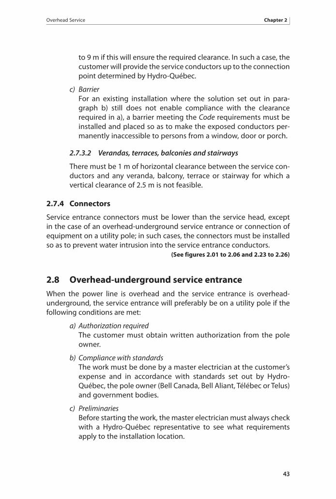
to 9 m if this will ensure the required clearance. In such a case, the customer will provide the service conductors up to the connection point determined by Hydro-Québec.
c) Barrier For an existing installation where the solution set out in para-
graph b) still does not enable compliance with the clearance required in a), a barrier meeting the Code requirements must be installed and placed so as to make the exposed conductors per-manently inaccessible to persons from a window, door or porch.
2.7.3.2 Verandas, terraces, balconies and stairways
There must be 1 m of horizontal clearance between the service con-ductors and any veranda, balcony, terrace or stairway for which a vertical clearance of 2.5 m is not feasible.
2.7.4 Connectors
Service entrance connectors must be lower than the service head, except in the case of an overhead-underground service entrance or connection of equipment on a utility pole; in such cases, the connectors must be installed so as to prevent water intrusion into the service entrance conductors. (See figures 2.01 to 2.06 and 2.23 to 2.26)
2.8 Overhead-underground service entrance When the power line is overhead and the service entrance is overhead-underground, the service entrance will preferably be on a utility pole if the following conditions are met:
a) Authorization required The customer must obtain written authorization from the pole
owner.
b) Compliance with standards The work must be done by a master electrician at the customer’s
expense and in accordance with standards set out by Hydro-Québec, the pole owner (Bell Canada, Bell Aliant, Télébec or Telus) and government bodies.
c) Preliminaries Before starting the work, the master electrician must always check
with a Hydro-Québec representative to see what requirements apply to the installation location.
43
Chapter 2 Overhead Service
4444
The pole owner will systematically reject any request for an overhead-underground service entrance on a pole that already has underground risers or electrical equipment other than street lights (including transformers).
d) Clearance and space on the pole The pole must have enough free space to accommodate the
conduits, and the clearances prescribed in figures 2.23 to 2.25 must be observed at all times. To this end, Hydro-Québec may, at the customer’s expense, raise the low-voltage conductors on the utility pole to accommodate the service entrance conduits. This procedure is required in most cases, since Hydro-Québec’s low-voltage conductors are usually located just above the neutral zone and the service head must be installed so that its top is at least 300 mm above the neutral zone.
No meter socket, protective device or disconnect switch may be mounted on the pole. (See figures 2.23 to 2.25)
e) Crossing of public thoroughfares The overhead-underground service entrance must never cross a
public thoroughfare unless the customer obtains authorization from the municipality or the Ministère des Transports.
f ) Requirements The overhead-underground service entrance must be installed in
accordance with technical, safety and operating requirements.
The master electrician must ensure that fill around the pole is restored to its initial condition.
Excavation at the foot of the pole must not exceed 600 mm in depth over half the perimeter of the pole, and the metal conduit must be buried to a depth of at least 300 mm.
g) Identifier A metal plate bearing installation identifiers (civic number or
equipment code) must be nailed or riveted to the pole near the cor-responding conduit at a height between 2 and 3 m above grade.
The identifiers must be engraved or permanently glued digits and letters at least 38 mm high. For service entrances, only the civic number for each service entrance is required. In the case of pole-mounted equipment, the plate must indicate the owner’s name and the type of equipment along with the civic number of the building closest to the equipment. Any other information is at the customer’s discretion, subject to Hydro-Québec approval.

Overhead Service Chapter 2
45
h) Expense Installation of the overhead-underground service entrance is at
the customer’s expense. Any subsequent relocation of the service entrance at the pole owner’s request is also at the customer’s expense.
If these conditions cannot be met, the customer must install, at his expense, his own pole and conduits in accordance with the Code and other appli-cable standards.
2.8.1 Technical requirements
2.8.1.1 Number and types of conduits
No more than two service conduits may be installed on a pole. The remaining space is reserved for telephone and cable distribution companies, which can each install one riser.
The conduits must be rigid metal and must be installed according to the Code.
The Code allows the use of rigid nonmetallic conduits on the cus-tomer pole. However, in locations where there is a risk of damage from machinery, such as lanes and driveways, nonmetallic conduits must be protected to a height of 2 m above grade by steel guards or appropriate raceways. (See figures 2.23 to 2.25)
2.8.1.2 Distance between conductors and service head
There must be at least 150 mm between the service loop conductors and the service head. It is important to maintain a minimum vertical separation of 1,000 mm (neutral zone) between the conductors (including drip loops) and the telecommunication cables. The master electrician must reach a prior agreement with a Hydro-Québec representative to ensure this requirement is met when installing the service head.
(See figures 2.23 to 2.25)
2.8.1.3 Conductors
The conductors exiting the service head must be at least 1.5 m long if the line consists of separate conductors, and 750 mm long if it con-sists of multiplex conductors. (See figures 2.23 to 2.25)
The overhead-underground service entrance must consist of a con-ductor that is continuous from the connection point to the service box.

Chapter 2 Overhead Service
46
2.8.1.4 Metal conduit
The metal conduit must be connected to the neutral by means of an approved ground-wire clamp. (See figures 2.23 to 2.25)
2.8.2 Connection point
The connection point is located at the supply point or on the customer pole in accordance with sections 2.7.2.5 and 2.7.2.6. (See figures 2.23 to 2.25)
2.9 Connection of equipment With overhead lines, the connection of pole-mounted equipment (apart from street lights) must meet the conditions below. Such equipment may include cable television or telecommunications equipment, amplifiers, boosters, sign lights or traffic lights.
Public lighting (including decorative lighting) is not covered by this pro-vision, as it is subject to specific standards. In certain situations and for reasons of public safety, Hydro-Québec may authorize the installation of public lighting on poles where there is already power system apparatus such as transformers.
a) Compliance with standards Installation is at the customer’s expense and must comply with
Hydro-Québec standards.
b) Preliminaries Before starting the work, the master electrician must always
check with a Hydro-Québec representative to see what require-ments apply to the installation location.
c) Space on the pole The pole must have enough free space to install one or more
conduits.
d) Requirements The equipment must be connected in accordance with technical,
safety and operating requirements.
e) Identification Refer to Section 2.8 g).

Overhead Service Chapter 2
47
2.9.1 Technical requirements
2.9.1.1 Number and types of conduits
Refer to Section 2.8.1.1. (See Figure 2.26)
2.9.1.2 Distance between conductors and service head
Refer to Section 2.8.1.2. (See Figure 2.26)
2.9.1.3 Conductors
Refer to Section 2.8.1.3. (See Figure 2.26)
2.9.1.4 Grounding
Pole-mounted equipment must be grounded by means of an approved ground-wire clamp in accordance with the instructions for the equipment in question. (See Figure 2.26)
2.9.2 Connection point
Refer to Section 2.8.2. (See Figure 2.26)


Underground Service Chapter 3
49
3 Underground Service
For underground service, the customer must contact a Hydro-Québec representative to find out about connection methods and any contribu-tions required.
3.1 Service entrance
3.1.1 Individual meter socket
Only one meter socket may be connected to the service loop and only one service entrance to that socket. (See figures 3.01 to 3.03)
In accordance with paragraph 6.2c) herein, the socket must be equipped with bolts to accommodate one-hole NEMA terminal lugs. (See Figure 3.01)
3.1.2 Multiple-meter mounting device
Only one multiple-meter mounting device may be connected to the ser-vice loop. (See Figure 3.04)
In accordance with paragraph 6.2c) herein, the connection box must be equipped with bolts to accommodate one-hole NEMA terminal lugs. The underground service conduit must terminate in the connection compartment.
3.1.3 Junction box
Each service loop conductor may connect to a maximum of two service entrance conductors. A transformer enclosure is not considered a junction box. (See figures 0.02 and 3.05 to 3.07)
3.1.4 Connection box for flat-rate service
For flat-rate service, only one connection box may be connected to the service loop.
For connection to the underground service loop, the connection box must be equipped with bolts to accommodate one-hole NEMA terminal lugs. (See Figure 3.10)
This box may be physically separate from or built into the equipment receiving the electricity supply. Any equipment having a built-in connection box, such as pad-mounted telecommunications equipment, must meet Hydro-Québec’s requirements and must be approved by Hydro-Québec before the service request is submitted.
49

Chapter 3 Underground Service
50
3.2 Connection point Depending on the installation, the connection point may be located in the meter socket, in a dedicated compartment of the multiple-meter mounting device, in the junction box or in the connection box for flat-rate service. (See figures 3.01 to 3.07 and 3.10)
Alternatively, it may be in a structure belonging to the customer (manhole or handhole). For certain installations supplied at 120/240 V and subject to a special agreement, it may be in a Hydro-Québec structure. In that case, a Hydro-Québec representative must supervise connection of the service entrance at the customer’s expense.
If the connection point is located in a structure belonging to the customer or to Hydro-Québec, the cable size must be between 2 AWG and 750 kcmil to ensure compatibility with Hydro-Québec’s multiway connector.
3.2.1 In the meter socket
The connection point may be indoors or outdoors, provided that the meter socket is on the supply side of the service box. (See figures 3.01 to 3.03)
3.2.2 In the multiple-meter mounting device
The connection point is located outdoors, on the supply side of the service boxes. (See Figure 3.04)
3.2.3 In the junction box
The connection point is inside the junction box in the following cases:
a) Indoors • On the supply side of one or two service boxes, two meter
sockets or one of each, located indoors. (See Figure 3.05)
• On the supply side of one or two individual meter sockets or one or two multiple-meter mounting devices, located outdoors.
(See Figure 3.06)
b) Outdoors • On the supply side of the service conduit.
• On the supply side of two individual meter sockets, two multi-ple-meter mounting devices or one of each. (See Figure 3.07)
For the purpose of undergrounding an overhead line, a type-3R junction box may be installed outdoors to facilitate connection of an existing customer installation. Such a junction box may be used for service entrances rated up to 600 A.

Underground Service Chapter 3
51
3.2.4 In the connection box for flat-rate service
The connection point is located on the bolts for one-hole NEMA terminal lugs in the compartment reserved for Hydro-Québec use. (See Figure 3.10)
3.2.5 In the customer structure
The connection point may be located in a structure belonging to the customer (manhole or handhole).
3.3 Underground conduit system The underground conduit system must be built by the customer at his own expense. A manhole or handhole, if necessary, must be provided on the cus-tomer’s property and at his own expense. The customer retains ownership of and responsibility for these items.
The conduit containing the service loop cables must be covered with 750 mm or more of fill, according to Hydro-Québec specifications.
3.4 Conduits
3.4.1 Description
A rigid conduit at least 75 mm in diameter, approved by Hydro-Québec, must be supplied and installed by the master electrician at the customer’s expense to link the meter socket, pullbox or junction box to the under-ground conduit system.
If the service box ratings total 600 A or more and the conduit system has type-L conduit bodies, the rigid PVC conduit must be at least 100 mm in diameter.
A 100/75-mm reducer bushing is then installed, if needed, between the rigid PVC conduit and the rest of the underground conduit system.
To facilitate cable pulling, bends with a minimum radius of 900 mm should be used on the entire underground conduit system. (See figures 3.01, 3.02, 3.04 and 3.07 to 3.10)
3.4.2 Conduit entrance
3.4.2.1 General requirements
To avoid drainage problems, the conduit should enter the building through a wall above grade at the most suitable location for the elec-trical installation. (See figures 3.02, 3.03, 3.08 and 3.09)

Chapter 3 Underground Service
52
3.4.2.2 Conduit entrances below grade
If, contrary to 3.4.2.1 above, the customer decides to have the conduit enter the building below grade, Hydro-Québec accepts no responsibility for any water infiltration problems. After install-ing or replacing service entrance conductors, the customer must have the conduit sealed at his own expense and in the presence of a Hydro-Québec representative. The customer must supply and use a product approved for this purpose and must not damage the conductors.
The customer bears sole responsibility for the design and construc-tion of the underground conduit system, and must take the neces-sary steps to prevent water from leaking into the building.
3.4.3 Conduit compatibility
Subject to Section 3.4.1, the customer conduit must have the same diameter as the distribution conduit, whether encased in concrete or buried directly.
3.4.4 Riser conduit on an exterior wall
A riser conduit may be mounted on an exterior wall provided the sum of bends does not exceed 180°, not counting the bend beneath the service entrance equipment. If the sum of bends exceeds 180°, the conduit run must first be approved by Hydro-Québec, which will determine whether the installation is feasible based on cable-pulling calculations. The bend joining the conduit at the foot of the wall to the rigid riser conduit must have a minimum radius of 900 mm. (See figures 3.01 to 3.04 and 3.07 to 3.09)
3.4.5 Expansion joint and adapter
The master electrician must install an expansion joint and adapter
• on an outdoor riser conduit connected directly to an individual meter socket or to the connection compartment in a multiple-meter mounting device; (See figures 3.01 and 3.04)
• on a conduit entering the building above grade; (See figures 3.02, 3.03, 3.08 and 3.09) and
• on a conduit entering a junction box outdoors. (See Figure 3.07)
3.4.6 Inspection and cleaning
Once work is completed, the master electrician shall, with a Hydro-Québec representative present, inspect and clean the conduits with a brush and steel wire joined to a mandrel. This requirement applies to all 347/600-V connec-tions; it applies to 120/240-V connections only at Hydro-Québec’s request.
52

Underground Service Chapter 3
53
3.4.7 Cable-pulling rope
For cable pulling, an industrial-grade polypropylene rope 6 mm or more in diameter must be inserted into every conduit that the master electrician must inspect and clean under Section 3.4.6.
3.4.8 Conduit sealing
Inside the customer’s building, the end of the conduit containing the ser-vice loop cables must be sealed by Hydro-Québec personnel after any cable installation work done by the distributor, except in the cases provided for in Section 3.4.2.2. (See figures 3.01 to 3.10 except 3.05)
3.4.9 Repair of above-grade conduit systems
Repairs may be carried out on a conduit system located above grade, in accor-dance with the Code and the job aid “Repairing an Existing Aboveground Conduit” at the end of this Standard.
3.5 Pullbox and junction box
3.5.1 Use
3.5.1.1 Pullbox
A pullbox may be used for underground cables supplying an indi-vidual meter socket with a maximum rating of 320 A at 120/240 V and installed indoors as provided for in Section 6.4.2.2. (See Figure 3.03)
A transformer enclosure is not considered a pullbox.
3.5.1.2 Junction box
In all cases not covered by Section 3.5.1.1, a junction box is required. A junction box allows connection of the service loop to one or two service entrances. The service entrance conductors inside the junc-tion box must be at least long enough to go once around the box.
3.5.2 Location of pullbox or junction box
3.5.2.1 Pullbox
The pullbox must be installed indoors at the spot where the service conduit enters the building. The bottom of the box must be at least 600 mm above the floor. The top of the box must be at least 200 mm below the ceiling and at most 2 m above the floor. (See Figure 3.03)
53

Chapter 3 Underground Service
54
3.5.2.2 Junction box
The junction box must be installed as follows:
a) Indoors In the place where the service conduit enters the building.
In cases where the sum of the service box ratings is less than 600 A, the bottom of the junction box must be at least 600 mm above the floor; the top must be at least 200 mm below the ceiling and at most 2 m above the floor. (See figures 3.05, 3.06 and 3.08)
In cases where the service box ratings total 600 A or more, the junction box must be installed at a height such that the conduit penetrating the wall arrives in a corner of the junction box. (See Figure 3.09)
b) Outdoors On the supply side of the customer service conduit, with the top
of the box 1.5 to 2 m above grade. (See Figure 3.07)
3.5.3 Specifications
The doors of pullboxes and junction boxes must have welded hinges with non-removable pins and a mechanism for affixing a seal.
Table 9 specifies the size of the junction box or pullbox, the number of mechanisms for affixing a seal and the thickness of the box walls. (See Figure 3.05 and Table 9)
3.5.4 Supply and installation
The pullbox or junction box and the conduit joining it to one or two service boxes, one or two individual meter sockets, or one or two multiple-meter mounting devices must be supplied, installed and grounded by the master electrician at the customer’s expense and in accordance with the Code.
Bonding must be done by the master electrician by means of a conductor separate from the neutral connecting the junction box or pullbox to the service box or meter socket.
3.5.5 Access and clearance
The pullbox or junction box must be installed in a readily accessible location. Clearance of 1 m in front of the box is required for at least the full width of the box. (See figures 3.06, 3.08 and 3.09)
54

Underground Service Chapter 3
55
3.5.6 Placement of conduits
3.5.6.1 Where the conduit enters the building
a) Sufficient clearance on wall If the building has two services at different voltages, the conduit
entrance must be placed so that a pullbox or junction box can be installed for each one.
b) Insufficient clearance on wall If the conduit entrance into the basement does not allow sufficient
clearance above grade or installation of two boxes close together, a type-LB conduit body can be used, provided the distance between the conduit entrance and the pullbox or junction box is as short as possible, given the location.
3.5.6.2 In the pullbox or junction box
The inlet conduit for service loop cables may terminate at the back, at one side or at the bottom of the pullbox or junction box but must be no farther than 200 mm from a corner. It may also terminate on the top of the pullbox or junction box if the conduit system drains toward outdoors. (See Figure 3.08)
In cases where the service box ratings total 600 A or more, the inlet conduit must terminate in the back of the box, less than 200 mm horizontally and vertically from one of the corners of the box. (See Figure 3.09)
The outlet conduits must not be farther than 200 mm from a corner when installed in a side of the box. They may be installed one behind the other. However, this distance may be increased to 300 mm when the service box ratings total 600 A or more. (See Figure 3.05)
In all cases, the conduit must be as close as possible to a corner of the box. The inlet and outlet conduits must never be installed in the same corner of the pullbox or junction box.
(See figures 3.03, 3.05 and 3.07 to 3.09)
3.5.7 Buildings with no basement
When a building has no usable basement and outdoor installation is pro-hibited by the competent authorities, the pullbox or junction box can be installed in a crawl space, provided it is kept dry, the clearances are as specified in Section 3.5.5 and the area is accessible at all times through a 685 x 760 mm or larger trapdoor and down a fixed vertical ladder.
55

Chapter 3 Underground Service
56
The trapdoor must be large enough to allow installation or replacement of a pullbox or junction box of the type required for the installation’s rating. Thus, the pullbox or junction box must fit through the trapdoor if there is no other opening.
Metering equipment must not be installed in this crawl space, however.
3.5.8 Plan required for special cases
If the conditions above cannot be met, a proposed alternative arrangement must be submitted to a Hydro-Québec representative for approval before the service entrance is modified or the underground line is built.
3.6 Connection box for flat-rate service
3.6.1 Use
The connection box for flat-rate service is used exclusively for unmetered installations connected to an underground 120/240-V line, as defined in Section 1.2.4.2.
3.6.2 Supply and installation
A customer who has a flat-rate contract must provide the connection box and have it installed outdoors by a master electrician. The underground service loop can then be connected in this box. (See Figure 3.10)
3.6.3 Specifications
The connection box for flat-rate service must be weatherproof, with a Hydro-Québec compartment 300 mm high by 200 mm wide by 150 mm deep. The customer compartment must have an adequate protective device and bus-bars connecting it to the Hydro-Québec compartment. Each compartment must open separately and have a mechanism for affixing a seal.
The bottom of the box must be at least 100 mm above grade. (See Figure 3.10)
3.7 Service loop
3.7.1 Supply and installation
Hydro-Québec supplies, installs and retains ownership of the service loop up to the point of connection to the customer’s electrical installation.
56

Underground Service Chapter 3
57
3.7.2 Customer’s handhole
The connection point may be located in a handhole belonging to the customer. The master electrician must leave an extra 3-m length of cable in the handhole. The customer retains ownership of and responsibility for customer installations.
The master electrician must contact a Hydro-Québec representative to find out about the applicable requirements.
3.7.3 Customer’s manhole
In the manhole, the master electrician must leave enough cable to go around the manhole once, so that the connection point can be located wherever determined by Hydro-Québec.
3.7.4 Service loop beneath or inside a building
Hydro-Québec will not supply a service loop beneath or inside a customer’s building or appurtenant structure unless the following three conditions are met:
1. The service conduit must be encased in concrete at least 50 mm thick.
2. The service loop must consist of a single span of cable running from the Hydro-Québec manhole or handhole to the connection point.
3. The sum of bends in the conduit must not exceed 180°, not counting the bend beneath the customer service equipment. If the sum of bends exceeds 180°, the master electrician must obtain Hydro-Québec’s prior approval for the proposed conduit route. Hydro-Québec will determine whether the installation is feasible based on cable-pulling calculations.
3.7.5 Clearances
A customer who installs a pool, appurtenant structure, platform or other permanent structure near the service loop or distribution line must ensure that the clearances (given in Table 10 herein) are compliant with the Code. (See Figure 3.11 and Table 10)

Chapter 3 Underground Service
58
3.8 Connection
3.8.1 Lugs
Hydro-Québec provides the lugs or multiway connectors needed to con-nect the customer’s installation, provided the conductors are one of the following gauges: 8, 6, 2, 1/0, 2/0, 3/0 or 4/0 AWG; or 250, 300, 350, 400, 500 or 750 kcmil.
Under Section 7.4 d), however, cables in a metering transformer enclosure must not exceed 500 kcmil. (See Figure 0.02)
Temporary Service Chapter 4
59
4 Temporary Service
4.1 Application This Chapter specifies the conditions for connecting an overhead or under-ground service loop for temporary service. It covers temporary electrical installations for buildings or structures under construction or demolition, as well as temporary experimental or test installations.
4.2 Service requirementsThe customer’s temporary installation must be compliant with the Code and this Standard. Before building such an installation, the master electrician or customer must contact a Hydro-Québec representative to reach an agreement on the points below:
a) Location A temporary service entrance must never be installed on a pole or
in an underground conduit for service loops.
b) Service entrance equipment shelter If the connection is three-phase or if metering transformers are
used, the equipment must be installed in a weatherproof shelter.
4.3 Overhead service The service attachment point must meet the requirements in Table 3. Overhead conductors must be supported by poles or other acceptable structures, as specified in the Code, spaced so as not to exceed the maximum allowable span for the type of conductor used. (See Table 3)
a) Distance between meter and power line The meter must be attached to the customer’s installation, which
must be located no more than 30 m from the Hydro-Québec line or from the line between the customer’s property and the adja-cent public thoroughfare. This requirement does not apply in the following cases:
• service to a residence;
• if the entire service entrance is visible from the connection point; or

Chapter 4 Temporary Service
60
• if only part of the service entrance is visible from the connec-tion point but the remaining part is visible from the metering equipment.
b) Supply and installation of service conductors For an installation to be connected to the Hydro-Québec line, the
master electrician must supply the conductors up to the line in accordance with Tables 4 and 6. The customer retains ownership of and responsibility for the conductors.
However, the connection must be done by Hydro-Québec. (See figures 4.01 to 4.03 and tables 4 and 6)
If the service entrance conductors are longer than necessary, the master electrician must roll the excess cable around the spool rack and move the tension clamp so that the sag between the customer’s spool rack and the utility pole meets the minimum clearances in the Code. If the excess cable is not rolled up, it can be cut when the service entrance is connected.
c) Crossing of public thoroughfares Where municipal bylaws permit, the temporary overhead service
entrance can cross public thoroughfares as long as the require-ments in Table 4 are met. (See Table 4)
4.4 Underground service Hydro-Québec provides its service loop cables and installs them through the customer’s underground conduit up to the connection point. Hydro-Québec retains ownership of and responsibility for its service loop and removes the cables when the contract is terminated. The customer is billed for the costs in accordance with the Conditions of Electricity Service.
If there is a Hydro-Québec handhole less than 5 m from the spot where the temporary service entrance support is to be installed, the service entrance may be connected in that handhole, subject to prior authorization by the Hydro-Québec representative, depending on the location, the space required, and the voltage and capacity available. In that case, Hydro-Québec will equip the handhole with a raised cover for running the cables to the temporary service entrance.
The master electrician must install adequate mechanical protection that will be permanent for the duration of the temporary service, including a sturdy grating at least 1.8 m high enclosing the handhole, the wiring (TECK90 or ACWU90 armoured cable installed with connectors approved for this use) and the temporary service entrance infrastructure, so as to ensure public safety

Temporary Service Chapter 4
61
by preventing anyone from entering the perimeter. Panels warning of the presence of live cables must be permanently attached to the grating at 2-m intervals and clearly visible.
Only Hydro-Québec may connect service entrance conductors to the service loop conductors. (See Figure 4.04)


Metering Chapter 5
63
5 Metering
5.1 Types of meteringHydro-Québec uses two types of metering: self-contained metering and instrument transformer metering.
5.2 Choice of metering equipment Metering equipment is selected based on service box ampacity, installed load and delivery point voltage.
5.3 120/240-V delivery point
5.3.1 Current rating of 320 A or less
Self-contained metering is used. A meter socket must be installed as specified in Chapter 6.
5.3.1.1 Exception
A transformer enclosure meeting the requirements in Chapter 7 and Table 11 must be put in place for an electrical installation of more than 200 A supporting dual energy.
5.3.2 Current rating of more than 320 A
Instrument metering with a current transformer is used. Either a transformer enclosure or a metal-clad substation compartment houses the equipment. Specifications for installing transformer enclosures and metal-clad substations are given in Chapter 7 and Chapter 8, respectively.
5.4 120/208-V delivery point
5.4.1 Current rating of 200 A or less
Subject to Section 1.2.2.3, self-contained metering is used. A meter socket must be installed as specified in Chapter 6.
5.4.2 Current rating of more than 200 A
Subject to Section 1.2.2.3, instrument metering with a current transformer is used. A current transformer enclosure must be installed as specified in Chapter 7.

Chapter 5 Metering
64
5.5 347/600-V delivery point
5.5.1 Current rating of 200 A or less
Subject to Section 5.5.1.1, self-contained metering is used. A meter socket must be installed as specified in Chapter 6.
The service box must have a ampacity of 200 A or less.
5.5.1.1 Exceptions
A transformer enclosure meeting the specifications in Chapter 7 and Table 11 must be installed in case of the following:
• electrical installations with dual-energy capability,
• metering equipment read through a telephone line.
5.5.2 Current rating of more than 200 A
Instrument metering with voltage and current transformers is used. Either a transformer enclosure or a metal-clad substation compartment houses the equipment. Specifications for installing transformer enclosures and metal-clad substations are given in Chapter 7 and Chapter 8, respectively.
5.6 600-V delivery point Subject to Section 1.2.2.1, instrument metering with voltage and current transformers is used. Either a transformer enclosure or a metal-clad sub-station compartment houses the equipment. Specifications for installing transformer enclosures and metal-clad substations are given in Chapter 7 and Chapter 8, respectively.
5.7 Service entrance equipment clearances
5.7.1 General
All service entrance equipment must be installed in a readily accessible location with a working clearance of at least 1 m from all temporary or per-manent obstructions in front, including to the finished grade/floor level. Installations of 1,200 A and over must meet the special requirements of the Code. In addition, in case of outdoor installations, the same clearance must be maintained between the equipment and the property line. (See figures 5.01 and 5.02)

Metering Chapter 5
65
5.7.2 Disconnect devices
When a disconnect device is part of the service entrance equipment, a working clearance of at least 1 m must be maintained on the side where the operating point is located. In the case of a front-operated disconnect, the clearance may be to the left or right of the switch, provided the operating point is less than 200 mm from the side.
To operate the disconnect, the operator may stand in front of the transformer enclosure, metering compartment, splitter trough, another disconnect or similar equipment. (See Figure 5.02)
5.7.3 Transformer enclosure
Minimum clearance of 600 mm must be maintained above the transformer enclosure, even if the meter is installed outdoors. (See Figure 0.03)
When the doors cannot open to 180°, the clearance specified in Section 5.7.1 must be increased by a distance equal to the width of the doors.
5.7.4 Combustible gas exhausts or vents
There must be at least 3 m of clearance between the meter socket or meter support and any combustible gas vent or exhaust duct. However, in case of a natural gas vent or exhaust duct, minimum clearance is only 1 m.
5.8 Grouped or outdoor metering equipment
5.8.1 Grouping of equipment for different voltages
Metering equipment for different voltages is normally grouped. However, an agreement can be reached with Hydro-Québec to have the equipment sepa-rated for the following reasons:
• to avoid excessive voltage drops,
• to facilitate connection to the line,
• lack of space in the existing meter room when a new electrical installation is added.
5.8.2 Enclosures or equipment assemblies approved for outdoor use
The location of metering equipment must meet the specifications in chapters 6 to 8. Exceptionally, if the location and equipment comply with sections 5.8.2.1 and 5.8.2.2, respectively, Hydro-Québec may accept the

Chapter 5 Metering
66
installation of metering equipment in an enclosure or equipment assembly approved for outdoor use under the Code in the following cases:
• Metering equipment not approved for outdoor use is installed in a cabinet 400 mm deep with a mounting plate and approved for its location. (See Figure 5.05)
• The equipment assembly is approved for outdoor use by the Régie du bâtiment du Québec following a special evaluation and is accepted by Hydro-Québec.
5.8.2.1 Location criteria
Metering equipment may only be installed in an enclosure or equip-ment assembly approved for outdoor use if one of the following conditions is met:
• The metering equipment must be installed at a maximum of 30 m from the line, as specified in Section 2.6.2, and no building served by the low-voltage electrical service can accommodate the mea-suring equipment at less than that distance.
• A security perimeter must be respected, as described in Section 6.3 or 7.1.
5.8.2.2 Equipment criteria
All metering equipment, including enclosures and equipment assemblies approved for outdoor use, must be:
• an installation covered by Section 6.6.2 or Chapter 7 that complies with all relevant requirements;
• in a readily accessible location;
• installed on the level and solidly secured to a wall, one or more customer-owned poles of class 7 or better (see Section 2.7.2.5) or any other support with equivalent characteristics;
• identified in accordance with Section 5.14.
A meter support must not be used with this type of installation.
5.9 Equipment on supply side of metering equipment All equipment installed on the supply side of metering equipment must have a mechanism for affixing a seal.

Metering Chapter 5
67
The following equipment may be installed on the supply side of metering equipment:
a) Customer instrument transformers Customers must obtain Hydro-Québec’s prior approval to install
on the supply side of metering equipment any transformer or other such device designed to protect their electrical installa-tion. Only customer transformers used for electrical protection or indicating electrical installation voltage may be installed on the supply side of Hydro-Québec metering equipment. Only a single voltage transformer and a single current transformer per phase are permitted, and the box containing this equipment must have a mechanism for affixing a seal. Customer equipment exclusively for electrical load management and metering must be installed on the load side of Hydro-Québec metering equipment.
b) Auxiliary services in a distribution substation in an annex In compliance with standard E.21-11, Service d’électricité en
basse tension à partir des postes distributeurs (the “Green Book”), auxiliary services (lighting, electrical outlets, ventilation and life safety systems) in a distribution substation in an annex must be connected on the supply side of metering equipment.
5.10 Protection of metering equipment For mechanical protection, Hydro-Québec may require that metering equipment not inside the meter room be protected by guard posts. Guard posts are not considered obstructions under Section 5.7, but at least 500 mm of clearance must be maintained between the guard post and the metering equipment. In addition, the doors of the box in which the metering equipment is placed must open completely.
5.11 Permanent platform and fixturesWhen the provisions herein so require, a permanent platform must be installed. This platform and its fixtures must meet the following requirements:
a) Width and depth The platform must be at least 1.2 m wide and deep enough
to allow 625 mm of clearance accounting for the depth of the enclosure and the width of a door opened to 90°.
b) Guardrail A guardrail at least 1 m high is required if the platform is 600 mm
or more above finished ground/floor level.

Chapter 5 Metering
68
c) Top rail of guardrail The mechanical strength of the top rail must comply with effective
Québec laws and regulations.
d) Stairway The platform must have a stairway with steps at least 200 mm
deep, uniform risers at most 200 mm high and a handrail beginning above the bottom step and 900 mm above that step’s nosing.
(See Figure 5.03)
5.12 Customer-owned low-voltage transformersMetering of a three-phase supply at the 120/240-V secondary voltage from a customer’s transformer is acceptable.
5.13 Fire pump As specified in the Code, no device capable of interrupting the circuit may be placed between the service box and a fire pump switch or controller, other than a circuit breaker lockable in ON position or a nonfused switch lockable in OFF position. (See Figure 5.04)
To determine the metering method for fire pumps and the capacity of the metering equipment, the ampacity of the disconnect on the load side of the metering equipment must be considered.
5.14 Permanent identification of service entrance equipment
The master electrician must identify service entrance equipment as specified in sections 5.14.1 and 5.14.2. Distribution panels located outside the premises receiving service must also be identified. However, a single meter socket that is an electrical installation’s only meter socket need not be identified.
5.14.1 Identification marking
The street address of the building or the unit number is used for identi-fication and, for all service entrances, must appear on every service box, transformer enclosure and distribution panel as well as on the fixed part of every meter socket.
If there is no street address, all components mentioned above must bear the same inscription.

Metering Chapter 5
69
If there is more than one meter per unit or customer, the specific use of each (e.g., fire pump) must be indicated. (See figures 3.04, 6.06, 6.07 and 6.09)
5.14.2 Methods of identification
The following methods of identification are allowed:
a) Embossed metal tag A metal tag pinned to the fixed part of the front of the meter
socket or a nonremovable tag if the detachable part is in place. The embossed inscription must be at least 5 mm high.
b) Engraved tag A permanent glued, riveted or screwed-down tag bearing an
engraved inscription at least 5 mm high. Chisel-engraved metal tags are permitted. For outdoor use, only glued nonmetallic tags are authorized.
c) Adhesive tape Indoors, a permanently glued label (from an electronic labeler)
bearing a black, red or blue inscription at least 5 mm high on a white background. Vinyl embossing tape is not permitted.
5.15 Identification of service entrance conductors In addition to being identified as specified in the Code, the phase conductors of polyphase installations must be color-coded with adhesive tape at the connection point, in the service box and in the transformer enclosure: red for phase A, black for phase B, blue for phase C and white for neutral. The phase conductors must be arranged from left to right (A, B, C) in the service box.
In addition to being identified as specified in the Code, parallel conductors of single-phase installations must be color-coded with adhesive tape at the connection point, in the service box and in the transformer enclosure: red for line 1, black for line 2 and white for neutral.
5.16 Safety precautionsThis section applies to all installations other than those covered by sec-tions 5.3.1 and 5.4.1. (See figures 6.10, 6.11, 7.04 and 7.05)
5.16.1 Padlocking
Service boxes and the first disconnects on feeders must be padlockable and located in the same room as metering equipment. Distribution panel main breakers must also be padlockable. If the main breaker of the distribution

Chapter 5 Metering
70
panel cannot be padlocked, the door of the distribution panel or all of the breakers in the panel must be lockable by means of a device approved for this use.
5.16.2 Zero-voltage testing
A disconnect or service box on the supply or load side of the metering equipment, or an approved splitter trough immediately on the load side of the metering equipment that has a door with manufacturer-designed pivots, must allow zero-voltage testing with a multimeter.

Self-Contained Metering Chapter 6
71
6 Self-Contained Metering
This Chapter lays down requirements for self-contained metering.
6.1 Meter socket supply and installation The meter socket is an integral part of the customer’s service entrance and must comply with the requirements of the Code and Section 6.2. The opening in the socket for the meter is reserved for the exclusive use of Hydro-Québec.
The master electrician installs and connects the meter socket at the cus-tomer’s expense in accordance with Hydro-Québec standards and ensures that all metering equipment is grounded as specified in the Code.
The line-side conductors are connected to the upper jaws of the meter socket. (See figures 3.01 to 3.03 and 6.02 to 6.05)
6.2 Meter socket specifications Only meter sockets on the list of products accepted by Hydro-Québec (found on the Web site for master electricians at www.hydroquebec.com/cmeq) are allowed. The meter socket must meet the following requirements:
a) Type of meter socket Only a square or rectangular meter socket complying with CSA
C22.2 No. 115-M (latest edition) is authorized for individual or grouped supply. (See figures 6.02 to 6.05 and 6.08)
b) Outdoor use Only a meter socket designed for outdoor use that complies
with effective standards may be used. The meter socket may include other devices or mechanisms, which must be accepted by Hydro-Québec. (See figures 6.02, 6.03 and 6.05)
c) Meter socket for underground service The meter socket must be equipped with bolts to accommodate
one-hole NEMA terminal lugs whenever the connection point for the underground supply service is on the meter socket terminals.
The bottom of the meter socket must accommodate a conduit with a diameter of 75 mm or more for the underground supply service. (See Figure 6.03)
71

Chapter 6 Self-Contained Metering
72
d) Bypass mechanism For a 320-A individual meter socket, a manual bypass mecha-
nism for the exclusive use of Hydro-Québec must be installed. Installation of a bypass mechanism is prohibited in all other cases.
e) Screw clamp It must be possible to attach to the meter socket a screw clamp
designed for affixing a seal. The list of accepted screw clamps can be found on the Hydro-Québec Web site for master electricians (www.hydroquebec.com/cmeq).
f ) Temporary cover Until the meter is installed, the opening on the front of the meter
socket must be protected by a temporary rigid watertight cover held in place by the screw clamp. The cover must have a dielectric strength appropriate for this use.
g) Jaws The meter socket jaws must ensure adequate electrical and
mechanical contact with the meter blades at all times. The number of socket jaws depends on the measured voltage of the electrical installation: • 120/240-V installations – four jaws;
• two-phase 120/208-V installations – five jaws;
• three-phase 120/208-V installations – seven jaws;
• 347/600-V installations – seven jaws.
h) Jumpers When modifying customer service entrances, master electri-
cians may temporarily install Hydro-Québec approved jumpers between socket jaws. The use of any other device is prohibited. Jumpers are strictly prohibited in all other circumstances. Master electricians may obtain jumpers (SAP 1018874) from Customer Services (1 877 COURANT).
i) Removable part The removable front part of the meter socket cover must be
secured by a bracket fastened by studs welded from the inside. The bracket must not be visible or accessible from the outside once the meter is installed and secured by the sealed screw clamp. Substitution of another device meeting these requirements must first be accepted by Hydro-Québec. (See Figure 6.01)

Self-Contained Metering Chapter 6
73
The socket may include other devices or mechanisms, which must be accepted by Hydro-Québec. In this case, the removable part giving access to the conductors must have a mechanism for affixing a seal. (See Figure 6.05)
j) Insulation of neutral conductor The full length of the neutral conductor inside an individual meter
socket must be insulated with a white jacket; if the jacket is of a different color, it must be marked with white tape. If the neutral conductor is bare, the master electrician must cover it with white insulating tape to prevent accidental contact with live parts inside the metering equipment. (See figures 6.02 to 6.05 and 6.08)
In self-contained metering installations in a saline environment or when a tingle voltage filter is used, the insulated neutral conductor must be continuous and must not be connected to any part of the metering equipment. The master electrician must then run another conductor from the ground terminal block in the service box to the one in the meter socket to ensure bonding. (See Figure 6.02)
k) Neutral conductor continuity In installations with individual sockets located in a saline environ-
ment or equipped with a tingle voltage filter, the meter socket’s insulated neutral conductor must be continuous and not con-nected to another part of the metering equipment. The master electrician must therefore run another conductor between the ground terminal block of the service box and that of the meter socket to ensure bonding. (See Figure 6.02)
In installations with a multiple-meter mounting device that are located in a saline environment, customer service entrance con-ductors must be connected using one-hole NEMA compression terminal lugs.
6.3 Location of meter sockets Meter sockets must be installed on the level in a readily accessible location and must be firmly secured to a wall of the building served, a customer-owned pole (if wood, class 7 or better, as specified in Section 2.7.2.5) or any other support with equivalent characteristics.
If access to the customer’s installation is restricted by a security perimeter, the meter socket must be installed outside this perimeter. This may be the case with a farm building, for example, or a building where access is restricted to certain hours or activities in the building require special clothing.

Chapter 6 Self-Contained Metering
74
6.3.1 Height of meter socket
a) Individual meter socket or multiple-meter mounting device The meter socket must be installed with the centre of its opening
1.2 m to 1.6 m above finished floor level or above a permanent platform meeting the requirements in Section 5.11. (See figures 3.02 to 3.04, 4.01 to 4.04, and 5.01)
b) Grouped supply The centre of the meter socket opening must be 600 mm to 1.6 m
above finished floor level or above a permanent platform meeting the requirements in Section 5.11. (See Figure 6.06)
When the meter socket is installed indoors, there must be at least 300 mm between the top of the meter socket and the finished ceiling or the bottom of the joists. (See Figure 5.01)
c) Metering centre The centre of the opening of the highest meter socket must be
no more than 2 m from finished floor level, and the centre of the opening of the lowest meter socket must be at least 600 mm from finished floor level. (See figures 6.07 and 6.09)
6.4 120/240-V delivery point
6.4.1 Accepted meter sockets
Only a meter socket meeting the requirements in Section 6.2 is accepted for 120/240-V installations.
6.4.2 Individual meter sockets and multiple-meter mounting devices
Individual meter sockets and multiple-meter mounting devices are installed outdoors, except under the circumstances specified in Section 6.4.2.2.
The meter socket or multiple-meter mounting device must always be installed between the connection point and the service box or boxes, except in case of grouped supply.
6.4.2.1 Outdoor installation
Individual meter sockets and multiple-meter mounting devices installed outdoors must be located in a place that meets the follow-ing criteria: (See Figure 6.02)
74

Self-Contained Metering Chapter 6
75
a) Access The meter socket must be installed in a readily accessible location
at ground level, ground-floor level, or higher-floor level.
b) Grouping of meter sockets When there is more than one meter socket, it is best to group the
meter sockets and install them with multiple-meter mounting devices. However, when adding a single delivery point to the customer’s service entrance of an existing installation, an additional individual meter socket can be used, subject to the provisions of sections 2.1.1 and 3.2.
To minimize quantity and length of conduits in the building and meet the integration requirements specified in paragraph 6.4.2.1 c), the master electrician should preferably use a meter socket or multiple-meter mounting device with a combined circuit breaker.
c) Integration Meter sockets are best located following the guide for visual inte-
gration (Guide des bonnes pratiques – Intégration visuelle des instal-lations de branchement aux bâtiments résidentiels) accessible from the Hydro-Québec Web site at www.hydroquebec.com/cmeq.
d) Îles de la Madeleine A type 4X meter socket must be used.
6.4.2.2 Indoor installation
Individual meter sockets may be installed inside a building only under the following conditions:
a) Polyphase service The building has polyphase service, as provided in Section 5.8, in
which case the individual meter socket must be installed in the building’s meter room.
b) Existing grouped supply The number of meter sockets of an existing grouped supply is
increased to optimize the capacity of the main service box.
c) Change on the load side of the service box A change is made between the service box and the disconnect
device on the supply side of the meter socket.
d) Îles de la Madeleine The meter socket must be installed indoors if it is not a type 4X
meter socket. (See figures 3.02 and 3.03)
75

Chapter 6 Self-Contained Metering
7676
When individual meter sockets are installed indoors, a disconnect device must be located in the same room on the load side of each meter socket. All electrical cabling from the meter socket to the cor-responding disconnect on the load side must be visible. (See Figure 6.04)
6.4.3 Grouped supply
When the meter socket is installed indoors under paragraph 6.4.2.2 b) or c), it must be placed between the service box and the corresponding disconnect device and in the same room as that equipment. (See Figure 6.06)
6.4.4 Metering centre
Use of a metering centre is authorized when there are more than six delivery points and a multiple-meter mounting device is not used. The metering centre must always be installed indoors, in the meaning of the Québec Construction Code – Chapter I, Building.
The disconnect device must be placed on the load side of the meter socket in the metering centre. (See Figure 6.07)
6.5 120/208-V delivery point
6.5.1 Accepted meter sockets
Only a meter socket meeting the requirements in Section 6.2 is authorized for 120/208-V installations.
6.5.2 Meter socket location and installation
All 120/208-V meter sockets must be located indoors and installed as specified in Section 6.3.
6.6 347/600-V delivery point
6.6.1 Accepted meter sockets
Only a meter socket meeting the requirements in Section 6.2 is authorized for wye-connected 347/600 V installations, solidly grounded neutral, with insulated neutral terminal.

Self-Contained Metering Chapter 6
77
6.6.2 Meter socket location and installation
Subject to Section 5.8.2, the meter socket must be located indoors and installed as specified in Section 6.3. In addition, the meter socket must always be located on the load side of the corresponding service box. (See Figure 6.08)
6.6.3 Metering centre location and installation
All meter sockets must be installed as specified in Section 6.3. In addition, Hydro-Québec authorizes use of a metering centre at 347/600 V. All meter sockets must be located on the load side of the corresponding disconnect device. (See Figure 6.09)
6.7 Zero-voltage testing As specified in Section 5.16.2, there must be an arrangement for zero-voltage testing on either the supply or load side of the meter socket.
If a disconnect device or a breaker-type service box is used on the supply side, a zero-voltage testing device must be installed on the load side of the meter socket. All electrical cabling between the meter socket and the zero-voltage testing device must be visible. (See figures 6.10 and 6.11)


Metering Equipment with Transformer Enclosures Chapter 7
79
7 Metering Equipment with Transformer Enclosures
This chapter describes requirements for metering equipment with a trans-former enclosure.
7.1 Supply and location of metering equipment Subject to Section 5.8.2, all metering equipment, with the exception of single-phase meters and their supports, must be installed in a readily acces-sible location in a single room of the building served. Single-phase meters and their supports must be installed outdoors in a readily accessible location.
The transformer enclosure is an integral part of the customer’s electrical installation and must meet the requirements of the Code and Section 7.2. The transformer enclosure is for the exclusive use of Hydro-Québec.
A dedicated disconnect device for the transformer enclosure must be installed immediately on the supply side of the enclosure at a distance of at least 100 mm. The entire length of the conduit between the disconnect device and the transformer enclosure must be visible. (See figures 7.01 and 7.03)
Metering equipment must be installed outside any security perimeter restrict-ing access to the customer’s installation. This may be the case, for example, with a farm building, a building where access is restricted to certain hours or a building where activities require special clothing.
7.1.1 Master electrician’s responsibilities
The master electrician installs the conduits, the meter support and the transformer enclosure at the customer’s expense and as specified in the Code and Hydro-Québec standards.
In addition, the master electrician ensures that all metering equipment and all removable metal parts are bonded to ground as per the manufacturer’s installation instructions and the requirements of the Code.
7.1.2 Hydro-Québec’s responsibilities
Hydro-Québec supplies the metering equipment and installs and connects meters, current and voltage transformers, the test-terminal block, secondary conductors and any connection lugs—provided the gauge of the conductors is 4, 3, 2, 1, 1/0, 2/0, 3/0 or 4/0 AWG; or 250, 300, 350, 400 or 500 kcmil.

Chapter 7 Metering Equipment with Transformer Enclosures
80
Hydro-Québec ensures bonding to ground between the meter support and the transformer enclosure when the conduit connecting them is not metal. However, the ground terminals must be supplied and installed by the master electrician.
7.2 Transformer enclosures
7.2.1 Accepted transformer enclosures
The list of accepted transformer enclosures is posted on the Hydro-Québec Web site for master electricians (www.hydroquebec.com/cmeq).
7.2.2 Transformer enclosure specifications
Table 11 gives requirements (dimensions, number of bolts, number of mechanisms for affixing a seal and gauge of metal) for the three types of transformer enclosures. (See Figure 0.03 and Table 11)
7.2.3 Transformer enclosure location
Subject to Section 5.8.2, transformer enclosures must be in a readily acces-sible location of the building served and firmly secured to a wall that is not subject to excessive vibrations. If the surface of the wall is not of wood, it must be covered, where the enclosure is to be installed, with a 19-mm plywood panel the width of the enclosure and extending at least 600 mm above the enclosure. In the case of a noncombustible building, the plywood must be protected as specified in the Code. (See figures 7.01 and 7.03)
7.2.4 Transformer enclosure height
The transformer enclosure must be installed so that its top is level and between 1.2 and 1.6 m above finished floor level. (See figures 7.01 and 7.03)
If the top of the transformer enclosure is more than 1.6 m from finished floor level, a permanent platform meeting the requirements specified in Section 5.11 must be installed.
7.3 ConduitsThere must be no conduit inlets or outlets on the top or back of the transformer enclosure. Supply-side and load-side conduits must be on opposite sides. The conduits must be as close as possible to the corners of the enclosure. (See figures 7.01 to 7.03)

Metering Equipment with Transformer Enclosures Chapter 7
81
7.3.1 Power conductor conduits
The conduits must not be more than 200 mm from a bottom corner of the transformer enclosure with a service box of less than 600 A and not more than 300 mm from the bottom corner with a service box of 600 A or more.
7.3.2 Conduit for metering conductors
The conduit running from a transformer enclosure to a meter support must be installed in a side of the box and no more than 200 mm from a top corner.
This conduit must
• enter the support from below, a side or the back;
• exit the building at least 300 mm above finished grade level, with the portion of the conduit on the outside wall of the building always at or above this level;
• not be buried, nor may any part of the conduit be buried;
• not be over 30 m long and have a minimum diameter of 27 mm for runs of up to 15 m and 35 mm for runs exceeding 15 m;
• not have more than two 90° bends without an accessible pulling point;
• have pulling points equipped for affixing self-adhesive seals and be readily accessible; and
• have a rope or wire for pulling the conductors, inserted by the master electrician.
7.4 Service entrance conductors Service entrance conductor requirements for instrument transformer meter-ing are as follows:
a) Phase conductors Conductors connected to current transformers must be sufficiently
long, free of splices and looped across the entire width of the trans-former enclosure. (See Figure 7.01)
b) Neutral conductor The master electrician must run the neutral conductor of single-
and three-phase installations along the bottom of the transformer enclosure. (See Figure 7.01)

Chapter 7 Metering Equipment with Transformer Enclosures
82
c) Insulated terminal For wye-connected 120/208-V or 347/600-V installations with
grounded neutral, a 10-AWG or thicker copper conductor with white or gray insulation must connect the service box neutral ter-minal to an insulated terminal inside the transformer enclosure on the side wall closest to the service box. (See Figure 7.01)
d) Size and number of conductors The size of the conductors must not exceed 500 kcmil. There
must be no more than three conductors per phase in parallel. (See Figure 7.01)
7.5 Meter
7.5.1 Location of single-phase meter
Subject to Section 5.8.2, the meter must be installed on an accepted meter support in a readily accessible location on an outside wall of the building served. The list of accepted meter supports can be found on the Web site for master electricians at www.hydroquebec.com/cmeq. (See Figure 7.02)
7.5.1.1 Height of meter support
The meter support must be installed so that the centre of the meter opening is between 1.2 m and 1.6 m from finished grade level or from a permanent platform that meets the requirements of Section 5.11. (See Figure 7.02)
7.5.2 Location of three-phase meter
Three-phase meters must be installed indoors. (See Figure 7.03)
7.6 Zero-voltage testing As specified in Section 5.16.2, a device for zero-voltage testing must be installed on either the supply or the load side of each transformer enclosure and in the same room as the enclosure. If a breaker-type disconnect device or service box is used on the supply side, or if part of the electrical cabling on the supply side of the transformer enclosure is not visible, the zero-voltage testing device must be installed on the load side of the enclosure. All electrical cabling between the transformer enclosure and the zero-voltage device must be visible. (See figures 7.04 and 7.05)

83
Metering Equipment with Metering Compartment Chapter 8
8 Metering Equipment with Metering Compartment
This chapter describes requirements for metering equipment with a metering compartment in a metal-clad substation.
8.1 Supply and location of metering equipment The metering equipment must be in a readily accessible location. If the metal-clad substation is indoors, the meter must be installed in the same room. A transformer enclosure must also be installed as specified in Section 7.2 If the metal-clad substation is outdoors, it must be in a metal enclosure designed by the same manufacturer and approved for this use. The meter can then be installed inside this enclosure, and a transformer enclosure must be installed as specified in Section 7.2. If the meter is installed outside the metal enclosure of the metal-clad substation, it must be placed in an outdoor cabinet, as specified in Section 8.5. The metering compartment is an integral part of the customer’s electrical installation and must comply with the requirements of the Code and Section 8.2. The compartment is reserved for the exclusive use of Hydro-Québec. A dedicated disconnect device for the metering compartment must be placed immediately on the supply side of the compartment. Each feeder on the load side of the metering compartment must have at least one disconnect device. Feeders with a fire pump must comply with Section 5.13. If access to the customer’s installation is restricted by a security perimeter, the metering equipment must be installed outside this perimeter. This may be the case with a farm building, for example, or a building where access is restricted to certain hours or activities in the building require special clothing. (See figures 8.01 to 8.03)
8.1.1 Responsibilities of the master electrician
The consulting engineer or master electrician must submit to the Hydro-Québec representative three copies of the shop drawings and circuit diagrams for the metal-clad substation and disconnect equipment to be installed. Hydro-Québec must accept those documents before the substation is built.

84
Chapter 8 Metering Equipment with Metering Compartment
The master electrician, at the customer’s expense, supplies the metal-clad substation and all fittings (including fixed grounding points), installs or has the manufacturer install the current transformers and connects the primary windings. The master electrician also supplies and installs the conductors, the fittings needed to connect the primary windings and the ducts or con-duits needed for voltage and current transformer secondary conductors.
In addition, the master electrician ensures that all measuring equipment and all removable metal parts are bonded to ground as per the manufacturer’s installation instructions and the requirements of the Code.
8.1.2 Hydro-Québec’s responsibilities
Hydro-Québec supplies the metering equipment and installs and connects the meters, voltage transformers, test-terminal block, connection blocks and metering transformer secondary conductors. Hydro-Québec connects only the secondary conductors of current transformers.
Hydro-Québec ensures bonding to ground between the metering compart-ment and the transformer enclosure or outdoor cabinet, as applicable, when the conduit connecting them is not metal. However, the ground terminals must be supplied and installed by the master electrician.
8.2 Metering compartment The metering compartment must be arranged so that temporary grounds can be adequately installed on the fixed grounding points.
The transformers must be arranged in the compartment so it is easy to inspect and maintain them and to connect secondary conductors. (See figures 8.01 to 8.03)
8.2.1 Applicable standards
The compartment containing the metering transformers must meet all requirements of CAN/CSA-C22.2 No. 31 (latest edition), Revenue Metering Equipment in Switchgear Assemblies; CAN/CSA-C71-1 (latest edition), Insulation Co-ordination – Part 1: Definitions, Principles and Rules; CAN/CSA-C71-2 (latest edition), Insulation Co-ordination – Part 2: Application Guide; and any applicable new standard. This compartment is reserved for the exclusive use of Hydro-Québec.

85
Metering Equipment with Metering Compartment Chapter 8
8.2.2 Metering compartment specifications
a) Height and width • Under 2,000 A Minimum height and width of the metering compartment is
750 mm.
• 2,000 A or over Minimum height and width of the metering compartment is
850 mm.
b) Clearance At least 50 mm of clearance must be left between the door of the
compartment and the transformers.
c) Access A panel must provide access to the metering transformers from
the front of the compartment. The panel must have welded hinges and nonremovable pins on one side and bolted hinges on the other, and it must have a mechanism for affixing a seal.
d) Connection block mounting plate So Hydro-Québec can install the connection block, the manufac-
turer or master electrician must attach a metal mounting plate as follows:
• The plate must have a usable surface area at least 75 mm wide by 300 mm long, a minimum thickness of 1.5 mm and be raised by 15 mm.
• The plate must be placed on the same side as the conduit running from the metering compartment to the transformer enclosure or the outdoor cabinet to make it easier to install the connection block and connect the secondary conductors.
e) Connection of primary transformers A copper or brass slotted round or Robertson head 10-32 bolt must
be installed on the supply side of the busbars so Hydro-Québec can easily connect the transformer primary conductors. This bolt is not required for 120/240-V installations.
f ) Fixed grounding points The fixed points are of tinned copper and the threaded rod of steel;
all parts must be zinc-plated. The threaded rod must be 13 mm in diameter and include a bolt, a flat washer and a lock washer.

86
Chapter 8 Metering Equipment with Metering Compartment
Fixed grounding points accepted by Hydro-Québec must be installed on busbars in the metering compartment, on the load side of the current transformers of all phases as well as on the ground bar. Sufficient clearance for attaching a temporary ground must be left around each fixed point.
8.2.2.1 Current transformers
a) Polarity Transformers must be arranged such that the polarity shown on
the equipment is on the supply side.
b) Height The bottom of the transformers in the compartment must be at
least 300 mm above finished floor level and the top of the trans-formers not more than 1.6 m.
c) Window-type transformers Any window-type transformer supplied by Hydro-Québec must be
secured with the centre of the window aligned with the busbars. Identification marks on the secondary terminals must be visible.
d) 120/240-V delivery point Hydro-Québec provides a two-phase current transformer.
8.2.2.2 Voltage transformers
Heights of support structures for installing voltage transformers must meet the requirements for current transformers set forth in paragraph 8.2.2.1 b).
8.3 Conduit from metering compartment to transformer enclosure or outdoor cabinet Conduit requirements are as follows:
• Minimum diameter: 41 mm for runs of up to 20 m and 63 mm for runs exceeding 20 m
• Maximum length: 140 m
• Diameter if buried: 75 mm
• No more than two 90° bends without an accessible pulling point
• Must enter the box within 200 mm of a corner
• Must have a rope or wire for pulling conductors (installed in the conduit by the master electrician) (See Figure 8.01)

87
Metering Equipment with Metering Compartment Chapter 8
• Pulling points must be in readily accessible locations and equipped for affixing self-adhesive seals.
8.4 Transformer enclosures If a transformer enclosure is used, it must be Type A and comply with Section 7.2. (See Figure 8.01 and Table 11)
8.4.1 Height of transformer enclosures
If the top of the transformer enclosure is more than 1.6 m from finished floor level, a permanent platform meeting the requirements in Section 5.11 must be installed.
8.5 Outdoor enclosures
8.5.1 Location of outdoor enclosures
Outdoor enclosures must be in a readily accessible location and firmly secured to a structure not subject to excessive vibration.
8.5.2 Specifications of outdoor enclosure
a) Size Outdoor cabinets must be at least 750 mm x 750 mm x 250 mm.
b) Sealing mechanism Outdoor cabinets must have at least one mechanism for affixing
a seal that makes it impossible to open the door once the seal is in place. If there is more than one sealing mechanism, this requirement applies to each. The sealing mechanism may be built into the lock.
c) Mounting plates The metering equipment must be installed on a mounting plate of
minimum 14-gauge metal. The mounting plate must be screwed onto the back of the box leaving about 50 mm clearance between the edge of the plate and the walls of the enclosure.
d) Doors Doors must have welded hinges with pins that cannot be removed
when the door is closed.
e) Types of protection Outdoor enclosures must be Type 3R, except in saline environ-
ments, in which case they must be Type 4X.

88
Chapter 8 Metering Equipment with Metering Compartment
f ) Locks All doors with handles must have at least two locks.
8.6 Zero-voltage testing The metering compartment must be arranged so that Hydro-Québec can perform a zero-voltage test using a multimeter. (See figures 8.02 and 8.03)

Figures

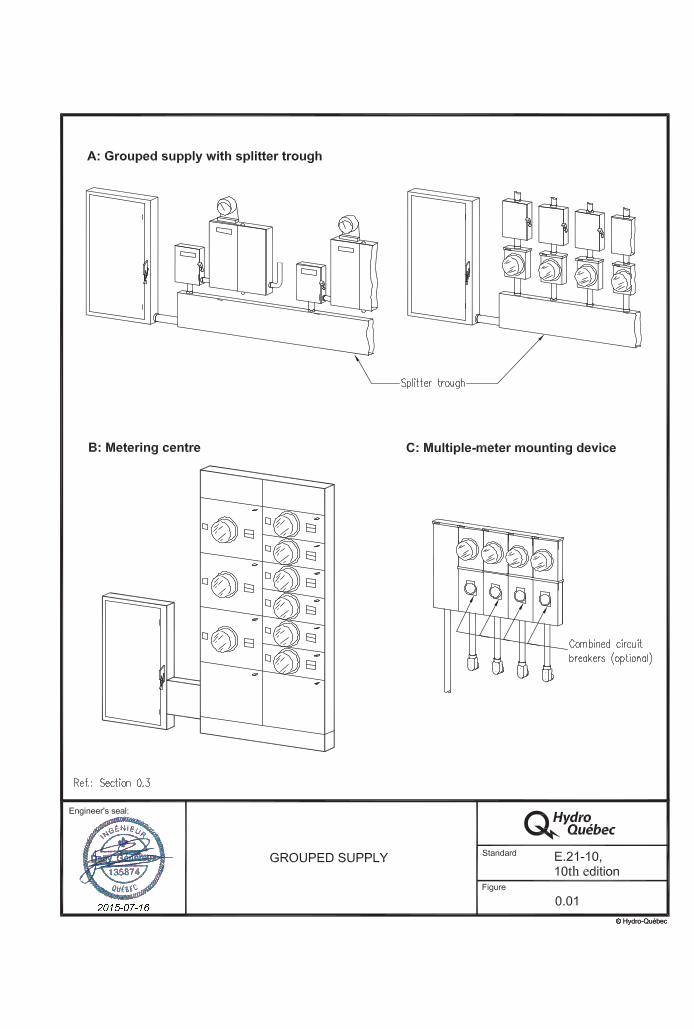


Tables


Tables
Table 1
Conversion Table
Dimensions
Millimetres Approximate equivalent in inches
Exact millimetre equivalent of inches given
6
13
19
25
38
50
63
75
100
150
200
250
300
400
450
500
600
750
915
1,000
1,200
1,500
1,600
1,800
2,000
2,030
3,000
1/4
1/2
3/4
1
1 1/2
2
2 1/2
3
4
6
8
10
12
16
18
20
24
30
36
40
48
60
63
72
79
80
120
6.35
12.70
19.05
25.40
38.10
50.80
63.50
76.20
101.60
152.40
203.20
254.00
304.80
404.40
457.20
508.00
609.60
762.00
914.40
1,016.00
1,219.20
1,524.00
1,600.20
1,828.80
2,006.61
2,032.00
3,048.00

Tables
Table 2
Service voltage limits – Allowable range
Type of lineNominal voltage
(volts)
At supply point(in volts)
Extreme operating conditions
Normal operating conditions
Single-phase 120/240
106/212
110/220
125/250
127/254
Three-phase 4 conductors 120/208Y 347/600Y
110/190 306/530
112/194 318/550
125/216 360/625
127/220 367/635
Three-phase 3 conductors 600
(existing installations)
530
550
625
635
Notes: Normal operating conditions – No improvements or corrective measures are required. Extreme operating conditions – Improvements or corrective measures must be planned based on an established program, but immediate action is not necessarily required.
Ref.: Section 1.2.2 and CAN3-C235-83 (latest edition)

Tables
Table 3
Mechanical strength of supports and spool racks
Rated ampacity or total rated ampacity
of service box(es)*Type of service loop conductors
Minimum strength at attachment
point
200 A or less 120/240 V Triplex, 2 AWG 2,670 N (275 kg)
347/600 V Quadruplex, 2 AWG 2,670 N (275 kg)
201 A to 400 A
120/240 V Triplex, 4/0 AWG (2/0 neutral) 2,670 N (275 kg)
347/600 V Quadruplex, 4/0 AWG (2/0 neutral) 2,670 N (275 kg)
401 A to 800 A
120/240 V 3 separate conductors 477 kcmil 6,900 N (700 kg)
347/600 V 4 separate conductors 477 kcmil 9,200 N (940 kg)
* In the case of a 120/240-V multiple-meter mounting device, the rated ampacity as shown on its nameplate may be used instead of the total rated ampacity of the service boxes it supplies.
Ref.: Sections 2.2.7, 2.2.12 a), 2.3.2, 4.3 and CAN/CSA-C22.3 No. 1

Tables
Table 4
Minimum spool rack height based on length of service loop
Length of service loop
Minimum height of spool rack above ground level**
Service loop crossing a public thoroughfare or
loading ramp access road*
Service loop crossing a driveway
Service loop crossing a
pedestrian area
30 m (98 ft.) 6.5 m (21.3 ft.) 5.6 m (18.4 ft.) 5.0 m (16.4 ft.)
25 m (82 ft.) 6.5 m (21.3 ft.) 5.6 m (18.4 ft.) 5.0 m (16.4 ft.)
20 m (66 ft.) 6.4 m (21 ft.) 5.4 m (17.7 ft.) 4.8 m (15.8 ft.)
15 m (49 ft.) 5.6 m (18.4 ft.) 4.7 m (16.4 ft.) 4.1 m (13.5 ft.)
* When the spool rack cannot be installed at the specified height without guying the existing support, Hydro-Québec relocates the conductors on the pole or erects a new pole to allow the connection.
** This assumes that grade is at the same elevation at the line supply point as at the connection point.
Notes: The spool rack must not be more than 8 m above grade. Heights must be increased by at least 0.61 m if telecommunications cabling is to be run beneath the service loop.
Ref.: Sections 2.2.8.1, 2.2.8.3, 2.7.2.1, 2.7.2.5, 4.3 b) and c)

Table 5
Distributor’s service loop over a public thoroughfare
Rated ampacity or total rated ampacity of
service box(es)
Distance Y
Distance X + Y
Additional pole needed to cross public thoroughfare***
Service loop provided
entirely by distributor
Service loop provided by customer
on own property
Distributor Distributor Customer pole
200 A or less≤ 30 m
≤ 30 m 0* 0* 0
> 30 m 1 1 0
> 30 m > 30 m 1** 1 1 or more
201 A or more ≤ 30 m
≤ 30 m 1 1 0
> 30 m 1 1 0
> 30 m > 30 m 1** 1 1 or more
* Under Section 2.2.8, the distributor in some instances provides a pole.
** A connection over 30 m long requires erecting one or more poles and possibly one or more guy wires, depending on the configuration. Charges established under the Conditions of Electricity Service in force are then payable. For some configurations it may be possible, subject to agreement with the distributor, to avoid erecting an additional pole to cross a public thoroughfare.
*** The distributor also provides this pole when the customer wishes to install an overhead-underground service entrance.
≤ Less than or equal to
> Greater than
Ref.: Sections 2.2.8.3 a) and 2.6.2
street
X
X
Legend
Width of public thoroughfareY Distance between connection point
and property lineConnection point Utility pole
Plus petit que ou égal àPlus grand que
�>
Y
Tables

Table 6
Last span of overhead service This table is based on clearances in CAN/CSA-C22.3 No. 1.
Type of lineVoltage Conductor type Maximum length of span
nearest to line (m)
Single-phase 120 V**
Duplex 4 NS75 (NS1)
NS75 FT1 (NSF2)
38 38
Single-phase 120/240 V
Triplex 2 NS75 (NS1)
NS75 FT1 (NSF2)
30 30
Triplex 2/0 NS75 (NS1)
NS75 FT1 (NSF2)
25 25
Triplex 4/0 NS75 (NS1)
NS75 FT1 (NSF2)
25 21
3 separate conductors No. 477 covered
Must be guyed (max. 6 m unguyed if max. tension = 100 N or 10 kg)*
Three-phase 347/600 V and 600 V
Quadruplex 2 NS75 (NS1)
NS75 FT1 (NSF2)
30 28
Quadruplex 4/0 (NS1)
NS75 FT1 (NSF2)
21 18
4 separate conductors No. 477 covered
Must be guyed (max. 6 m unguyed if max. tension = 100 N or 10 kg)*
* The maximum 6-m span nearest the line must not be taut (maximum: 100 N or 10 kg).
** For public lighting only.
Ref.: Sections 2.6.2, 2.7.2.5, 4.3 b) and figures 2.16 and 2.21
Note: Parallel conductors are allowed, provided that they are installed as specified in the Code.
Tables
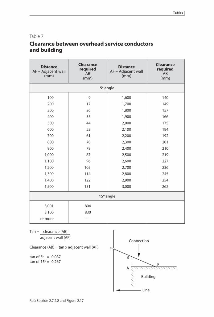
Table 7
Clearance between overhead service conductors and building
DistanceAF – Adjacent wall
(mm)
Clearance required
AB (mm)
DistanceAF – Adjacent wall
(mm)
Clearance required
AB (mm)
5o angle
100
200
300
400
500
600
700
800
900
1,000
1,100
1,200
1,300
1,400
1,500
9
17
26
35
44
52
61
70
78
87
96
105
114
122
131
1,600
1,700
1,800
1,900
2,000
2,100
2,200
2,300
2,400
2,500
2,600
2,700
2,800
2,900
3,000
140
149
157
166
175
184
192
201
210
219
227
236
245
254
262
15o angle
3,001
3,100
or more
804
830
---
Ref.: Section 2.7.2.2 and Figure 2.17
Tan = clearance (AB) adjacent wall (AF)
Clearance (AB) = tan x adjacent wall (AF)
tan of 5o = 0.087tan of 15o = 0.267
B
FA
P
Line
Connection
Building
Tables

Table 8
Ladder height-to-base range
Height of resting point (mm)
Minimum horizontal distance to base
(mm)
Maximum horizontal distance to base
(mm)
3,600
3,900
4,200
4,500
4,800
5,100
5,400
5,700
6,000
6,300
6,600
6,900
7,200
7,500
7,800
8,100
8,400
900
975
1,050
1,125
1,200
1,275
1,350
1,425
1,500
1,575
1,650
1,725
1,800
1,875
1,950
2,025
2,100
1,200
1,300
1,400
1,500
1,600
1,700
1,800
1,900
2,000
2,100
2,200
2,300
2,400
2,500
2,600
2,700
2,800
Ref.: Section 2.7.1 and Figure 2.20
Tables
HeightLadder
Horizontal distance
Resting point
Wall
Grade
min.
max.
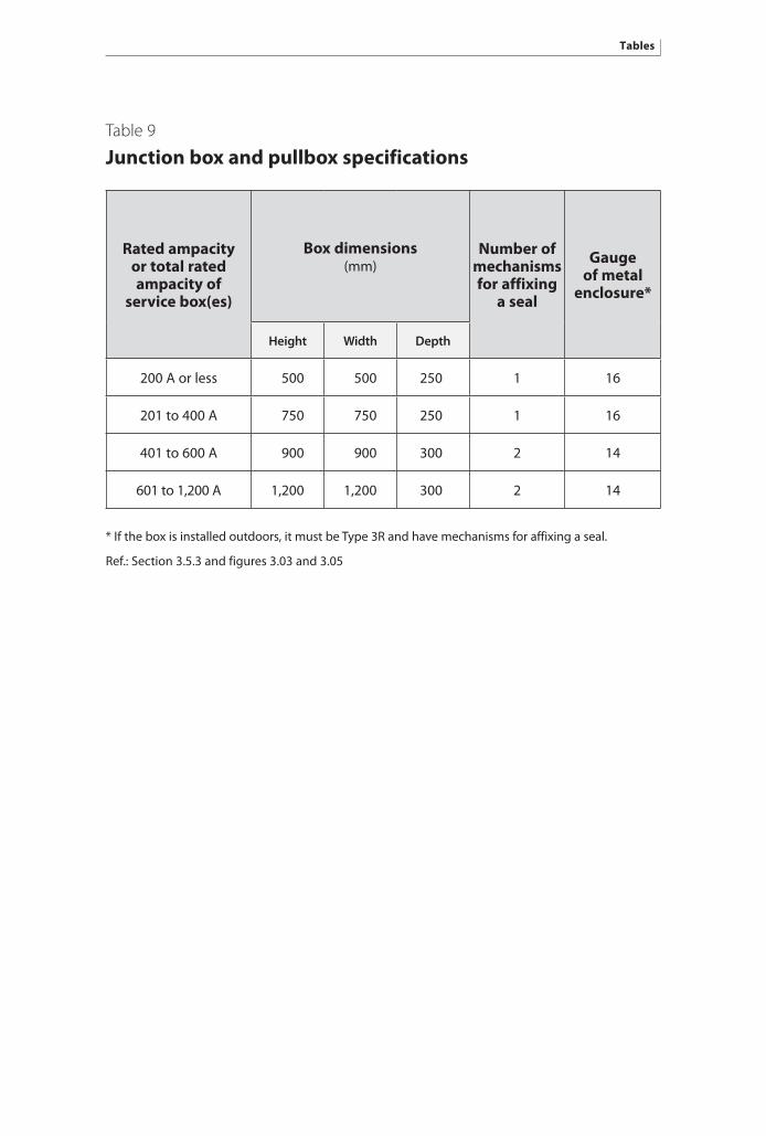
Table 9
Junction box and pullbox specifications
Rated ampacity or total rated ampacity of
service box(es)
Box dimensions (mm)
Number of mechanisms for affixing
a seal
Gauge of metal
enclosure*
Height Width Depth
200 A or less 500 500 250 1 16
201 to 400 A 750 750 250 1 16
401 to 600 A 900 900 300 2 14
601 to 1,200 A 1,200 1,200 300 2 14
* If the box is installed outdoors, it must be Type 3R and have mechanisms for affixing a seal.
Ref.: Section 3.5.3 and figures 3.03 and 3.05
Tables

Tables
Table 10
Minimum horizontal clearance between underground service conductors and pools
Type of installation Minimum horizontal clearance (m)
Direct buried unjacketed cable with bare neutral
or cables with a semi-conducting jacket
Cable with a non-conductive
jacket or in a non-conductive conduit
Telecommunications cabling 1.5 1.0
0 to 750 V 1.5 1.0
751 to 15,000 V 3.0 1.5
15,001 to 28,000 V 6.0 2.0
Ref.: Section 3.7.5 and Figure 3.11 of this Standard, and Section 68-056 and Table 61 of the Code.
Notes: Voltages are phase-to-phase. Clearance from non-conducting conduits is measured from the nearest edge of the conduit
to the inside wall of the pool.

Tables
Table 11
Transformer enclosure or meter socket
A – Type of enclosure or socket
Rated ampacity of service box overcurrent protection
Installation with one conductor per phase
Installation with parallel conductors
(maximum of three per phase)
Supply voltage Supply voltage
120/ 240 V
120/ 208 V
347/ 600 V 600 V** 120/
240 V120/
208 V347/
600 V 600 V**
200 A and under Socket SocketSocket
or type A*
Type A – – – –
201 to 320 ASocket
or type A*
Type B Type B Type BSocket
or type A*
Type B Type B Type B
321 to 400 A Type A Type B Type B Type B Type A Type B Type B Type B
401 to 600 A Type A Type B Type B Type B Type B Type C Type C Type C
601 A and over – – – – Type C Type C Type C Type C
* Electrical installation with dual-energy capability or metering equipment with a telephone line connection.
** Existing installation, or standard voltage not offered.
B – Transformer enclosure specifications according to type
Type of enclosure Dimensions Gauge of
box metalGauge of
plate metalNumber of bolts*
Number of mechanisms for affixing
a seal*
A 750 x 750 x 250 mm 16 14 2 2
B 900 x 900 x 300 mm 14 14 2 2
C 1,200 x 1,200 x 300 mm 14 14 2 2
* Bolts and mechanisms for affixing a seal may be combined in the same device.
Ref.: Sections 5.3.1.1, 5.5.1.1, 7.2.2, 8.4 and Figure 0.03

Tables
Table 12
Compression connectorsCombinations: aluminum-aluminum or aluminum-copper
Customer conductor Distribution conductor
Groove A (Run)
Groove B (Tap)Insulating
cover4 Al or 4 ACSR or 2 Al or 2 ACSR
Manufacturer Manufacturer Compression tool
Blackburn Burndy Homac Ilsco Kearney Thomas & Betts Burndy Manual Hydraulic 12 t
Catalogue number Catalogue number
Number of indents Die
10, folded in two
HT-6 506-82 C5C 4 2 O
8, folded in two
HT-6 506-82 C5C 4 2 O
6 YHO1 HT-6 506-82 C5C CCO 4 2 O
4 YHO1 HT-6 506-82 C5C CCO 4 2 O
3 YHO1 OB-101 HT-6 506-82 C5C CCO 4 2 O
2 WR-189 YHO2 OB-101 HT-8 508-82 C7C CCO 5 2 O
1 WR-189 YHO2 OB-101 HT-8 508-82 C7C CCO 5 2 O
1/0 WR-189 YHO2 DB-202 HT-8 508-82 C7C CCO 5 2 O
2/0 WR-189 YHO2* DB-202 HT-8 508-82 C7C CCO 5 2 O
3/0 WR-289 YHD3* DB-202 HT-2 502-82 C7C CCD 5 2 D
4/0 WR-379 YHD5 HT-3 503-82 C7C CCD 5 2 D
250 kcmil WR-379 YHD5 HT-3 503-82 C7C CCD 5 2 D
• Conductors must be brushed before connection.
• Copper conductor must be placed beneath aluminum conductor.
• Cables to replace: conductors smaller than 2 AWG.
• Compliant cables: 1 No. 2 ACSR neutral messenger and 2 No. 2 Al conductors (200 A or under).
• This list is for reference only. The master electrician must ensure that connectors approved for the application are used and that the manufacturer has not made changes to the products.
Ref: Section 2.4.4

Table 13
Insulation-piercing connectors (saline environment)Combinations: aluminum-aluminum or aluminum-copper
Customer conductor Distribution conductor
Groove A (Run)
Groove B (Tap)
4 Al to 4/0 Al 2 Al to 4/0 Al
Manufacturer
AMP SICAME
Catalogue number
4 KZ3-4/0 TTD 2710 F BHQ
3 KZ3-4/0 TTD 2710 F BHQ
2 KZ3-4/0 TTD 2710 F BHQ
1 KZ3-4/0 TTD 2710 F BHQ
1/0 KZ3-4/0 TTD 2710 F BHQ
2/0 KZ3-4/0 TTD 2710 F BHQ
3/0 KZ3-4/0 TTD 2710 F BHQ
4/0 KZ3-4/0 TTD 2710 F BHQ
250 kcmil KZ4
• These connectors must only be used in a saline environment.
• Cables to replace: Conductors smaller than 2 AWG.
• Compliant cables: 1 No. 2 ACSR neutral messenger and 2 No. 2 Al conductors (200 A and less).
• Single-use connector.
• This list is for reference only. The master electrician must ensure that connectors approved for the application are used and that the manufacturer has not made changes to the products.
Ref.: Section 2.4.4
Tables

Tables
Table 14
Overhead service conductor clearances required under the Code
Position of conductor Minimum clearance (m)
Above highway, street, alley or lane 5.5
Above driveway to a residential garage 4.0
Above driveway to industrial or commercial premises 5.0
Above ground normally accessible to pedestrians only 3.5
Above a balcony, porch, terrace or stairs (accessible area) 2.5
To the left or right of a balcony, porch, terrace or stairs* 1.0
To the left, right or above a window, door or porch** 1.0
Near pools, spas and related facilities See Figure 2.15
* Clearance required if 2.5 m of clearance above is not possible.
** Not required if the conductors (including drip loops) run above the window, door or porch.
Note: Clearances required under the Code apply to conditions existing at the time of installation and not to maximum sag. The clearances specified exceed those required under CSA-C22.3 No. 1.
See rules 6-112, 12-310 and 68-054 of the Code for further information.
Ref: Sections 2.2.3 and 2.7.3, Figure 2.15

181
Job Aids


Job AidsJob Aids
Work at the Connection Point: Disconnecting 120/240-V (200 A or less)
Overhead Service
Standard E.21-1010th edition
Engineer’s seal :
Job Aid 2.01
1 Open customer’s
main switch
2 Install protective
equipment• Cover neutral and one service entrance conductor with insulating blanket.• Leave only the conductor being worked on exposed.
3 Disconnect one service
entrance phase• Cut conductor.
4 Insulate end of service entrance
conductor• Insulate conductor on supply and load sides with insulating tape.
5 Repeat steps 3 and 4 for
other phase
6 Remove protective
equipment
7 Disconnect customer’s neutral
• Cut conductor.
Disconnection
Requirements• Electrical contractor’s licence• Journeyman construction electrician’s certificate
Tools and materials*• Cable cutter• Fibreglass ladder• Tape
* Must comply with CAN/CSA Z462 (latest edition).
Protective equipment The protective equipment specified in CAN/CSA Z462 (latest edition) is mandatory on the jobsite and must be used as stipulated therein.
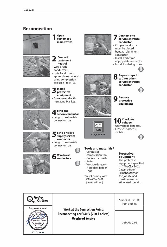
Job Aids Job Aids
Work at the Connection Point: Reconnecting 120/240-V (200 A or less)
Overhead Service
Standard E.21-1010th edition
Engineer’s seal
Job Aid 2.02
1 Open customer’s
main switch
2 Connect customer’s
neutral• Wire brush conductors.• Install and crimp appropriate connector using compression tool (see Table 12).
3 Install protective
equipment• Cover neutral with insulating blanket.
4 Strip one service conductor
• Length must match connector size.
5 Strip one live supply service
conductor • Length must match connector size.
6 Wire brush conductors
7 Connect one service entrance
conductor• Copper conductor must be placed beneath aluminum conductor.• Install and crimp appropriate connector.• Install insulating cover.
8 Repeat steps 4 to 7 for other
service entrance conductor
9 Remove protective
equipment
10 Check for voltage
• Use voltage detector.• Close customer’s switch.
Reconnection
Tools and materials*• Connector compression tool• Connector brush• Knife• Voltage detector• Fibreglass ladder• Tape
* Must comply with CAN/CSA Z462 (latest edition).
Protective equipment The protective equipment specified in CAN/CSA Z462 (latest edition) is mandatory on the jobsite and must be used as stipulated therein.

Job AidsJob Aids
Work at the Connection Point: Disconnecting 120/240-V (200 A or less)
Overhead Service in a Saline Environment
Standard E.21-1010th edition
Engineer’s seal
Job Aid 2.03
1 Open customer’s main switch
2 Install protective
equipment• Cover neutral and one service entrance conductor with insulating blanket.• Leave only the conductor being worked on exposed.
3 Disconnect one service
entrance phase• Unbolt insulation- piercing connector or cut conductor if necessary.
4 Insulate end of service
conductor• Insulate conductor on supply and load sides with insulating tape.
5 Repeat steps 3 and 4 for
other phase
6 Remove protective
equipment
7 Disconnect customer’s neutral
• Unbolt insulation- piercing connector or cut conductor if necessary.
Disconnection in a saline environment
Requirements• Electrical contractor’s licence• Journeyman construction electrician’s certificate
Tools and materials*• 9/16-in. ratchet wrench• Cable cutter• Fibreglass ladder• Tape
* Must comply with CAN/CSA Z462 (latest edition).
Protective equipment The protective equipment specified in CAN/CSA Z462 (latest edition) is mandatory on the jobsite and must be used as stipulated therein.

Work at the Connection Point: Reconnecting 120/240-V (200 A or less)
Overhead Service in a Saline Environment
Standard E.21-1010th edition
Engineer’s seal
Job Aid 2.04
Reconnection in a saline environment
1 Open customer’s main switch
2 Connect customer’s
neutral• Install appropriate insulation-piercing connector.• Tighten until rupture nut/bolt breaks.
3 Install protective
equipment• Cover neutral with insulating blanket.
4 Insulate end of service
conductor• Install appropriate insulation-piercing connector.• Tighten until rupture nut/bolt breaks.
5 Repeat Step 4 for other service
entrance conductor
6 Remove protective
equipment
7 Check for voltage
• Use voltage detector.• Close customer’s switch.
Requirements• Electrical contractor’s licence• Journeyman construction electrician’s certificate
Tools and materials*• 9/16-in. ratchet wrench• Fibreglass ladder• Voltage detector
* Must comply with CAN/CSA Z462 (latest edition).
Protective equipment The protective equipment specified in CAN/CSA Z462 (latest edition) is mandatory on the jobsite and must be used as stipulated therein.
Job Aids Job Aids

7 Disconnect customer’s neutral
• Cut neutral conductor.
8 Relocate supply service
• Attach hook of Howe wire tool to new spool rack. • Attach bulldog grip and other end of Howe wire tool to service to be relocated. • Pick up slack using wire tool to free service entrance tension clamp of all tension.
9 Remove service entrance tension
clamp Note: Leave wire tool in place until service entrance tension clamp is installed on new spool rack.
Disconnection with relocation
1 Open customer’s main switch
2 Install protective equipment
• Cover neutral and one service entrance conductor with insulating blanket. • Leave only the conductor being worked on exposed.
3 Disconnect one service
entrance phase • Cut conductor.
4 Insulate end of service entrance
conductor • Insulate conductor on supply and load sides with insulating tape.
5 Repeat steps 2, 3 and 4 for
other phase
6 Remove protective equipment
Work at the Connection Point: Disconnecting and Relocating
120/240-V (200 A or less) Overhead Service
Standard E.21-1010th edition
Engineer’s seal
Job Aid 2.05 (1 of 2)
Job AidsJob Aids

The work described herein is performed on energized installations in accordance with the “additional hazards or increased risk” provision of Section 4.3.2.2.1 of CAN/CSA Z462-12. In this case, de-energizing by operating the medium-voltage cutout switch on the supply side of the transformer would be more hazardous.
Requirements• Electrical contractor’s licence• Journeyman’s construction electrician’s certificate
Tools and materials* • Fibreglass ladder rated grade 1 (heavy load rating) under CAN3-Z11-M81 • Clamp• Insulating tape • Howe wire tool• Bulldog grip • Voltage detector rated CAT IV under CSA C22.2 No. 61010
* Must comply with CAN/CSA Z462 (latest edition).
Protective equipment The protective equipment specified in CAN/CSA Z462 (latest edition) is mandatory on the jobsite and must be used as stipulated therein.
Approved models of service entrance tension clamp• Al for conductor No. 4 and No. 2, ACSR SL 100%, MacLean Power Systems• Anodized Al for conductor No. 4 and No. 2, ACSR SL 100%, coated (polluted environment), Blackburn• With plastic jaws for conductor No. 4 and No. 2, ACSR SL, coated (saline environment), Cicame Energie
Howe wire tool and bulldog grip 1 Howe wire tool: used for tensioning or loosening small-gauge conductors (Klein Tools) 2 Bulldog grip:used as an anchor point to a loop conductor (Klein Tools)
Work at the Connection Point: Disconnecting and Relocating
120/240-V (200 A or less)Overhead Service
Standard E.21-1010th edition
Engineer’s seal
Job Aid 2.05 (2 of 2)
Job Aids Job Aids

Reconnection with relocation
Make sure the customer’s main
switch is open
Install service entrance tension
clamp • Tension service loop adequately. • Cut and remove excess length, if any, from service loop.• Attach service entrance tension clamp to service loop and to new spool rack.• Remove Howe wire tool and bulldog grip.
Reconnect customer’s neutral
to service loop • Wire brush neutral conductors (lineworker’s wire brush shown). • Install and crimp appropriate connector using compression tool (see tables 12 and 13).
Install protective equipment
• Cover neutral with insulating blanket.
4
3
2
1 Strip one service conductor
• Length must match connector size.
Strip one live service conductor
• Length must match connector size.
Wire brush conductors
Connect one service entrance
conductor • Place copper conductor beneath aluminum conductor. • Install and crimp appropriate connector. • Install insulating cover.
Repeat steps 4 to 8 for other service
entrance conductor
Remove protective
equipment
Check for voltage
• Use a voltage detector. • Close customer’s switch.
5
6
78
9
10
11
Work at the Connection Point: Relocating and Reconnecting
120/240-V (200 A or less)Overhead Service
Standard E.21-1010th edition
Engineer’s seal
Job Aid 2.06 (1 of 2)
Job AidsJob Aids

The work described herein is performed on energized installations in accordance with the “additional hazards or increased risk” provision of Section 4.3.2.2.1 of CAN/CSA Z462-12. In this case, de-energizing by operating the medium-voltage cutout switch on the supply side of the transformer would be more hazardous.
Requirements• Electrical contractor’s licence• Journeyman’s construction electrician’s certificate
Tools and materials* • Fibreglass ladder rated grade 1 (heavy load rating) under CAN3-Z11-M81 • Clamp• Insulating tape • Howe wire tool• Bulldog grip • Voltage detector rated CAT IV under CSA C22.2 No. 61010
* Must comply with CAN/CSA Z462 (latest edition).
Protective equipment The protective equipment specified in CAN/CSA Z462 (latest edition) is mandatory on the jobsite and must be used as stipulated therein.
Howe wire tool and bulldog grip 1 Howe wire tool:used for tensioning orloosening small-gaugeconductors (Klein Tools) 2 Bulldog grip:used as an anchorpoint to a loopconductor (Klein Tools)
Work at the Connection Point: Relocating and Reconnecting
120/240-V (200 A or less) Overhead Service
Standard E.21-1010th edition
Engineer’s seal
Job Aid 2.06 (2 of 2)
Job Aids Job Aids

Repair of conduit
• 9-mm (3/8-in.) stainless steel band clamp
Component Description
• Split conduit, rigid • Variable diameter
• Two split couplings, rigid PVC • Variable diameter • Coupling generally not required if each end of the split conduit is equipped with an integral bell adapter
• Clasp for 9-mm (3/8-in) stainless steel band clamp
Reference: Section 3.4.10
Repairing an Existing Aboveground Conduit
Standard E.21-1010th edition
Engineer’s seal
Job Aid 3.01 (1 of 3)
Job AidsJob Aids

Assembly method
1 Preparing the conduit
• Cut the conduit from the underground system at least 150 mm beneath the junction box or meter socket, taking care not to damage the live cables inside the conduit. • Adjust the expansion joint opening to manufacturer’s recommendations.
2 Preparing and installing the split conduit
• Cut the split conduit to the appropriate length. It must be 25 mm* shorter than the missing section of supply conduit. • Clean the ends of the split conduit. • Apply a layer of solvent primer and then solvent cement on the split conduit’s interlocking joints and mating ends, as applicable. • Install the conduit so it covers the exposed cable beneath the junction box or meter socket.
* If conduits with integral bell adapters are used, consult the manufacturer’s instructions to determine length.
Reference: Section 3.4.10
Repairing an Existing Aboveground Conduit
Standard E.21-1010th edition
Engineer’s seal
Job Aid 3.01 (2 of 3)
Job Aids Job Aids

3 Preparing and installing split couplings
Proceed as follows for each end of a split conduit without an integral bell adapter: • Clean the inside of the couplings.• Apply a layer of solvent primer and then solvent cement on the outside of the conduit over an area matching the size of the split coupling. • Do likewise for each half of the split coupling, making sure to cover interlocking edges. • Install the coupling on either side of the split conduit with its interlocking edges at 90° to the interlocking joint of the conduit.
Warning: Install the male half of the coupling before the female half.
4 Installing stainless steel band clamps and rotating the service conduit
• Install two non-detachable stainless steel band clamps around each coupling thus assembled or on each of the mating ends of the assembled split conduit. • Install non-detachable stainless steel band clamps at least every 500 mm along any repair run exceeding 500 mm. • Rotate the service conduit so the clasps of the stainless steel band clamps are on the side of the conduit.
1) Insert the male half of the coupling.
2) Insert the female half of the coupling.
Reference: Section 3.4.10
Repairing an Existing Aboveground Conduit
Standard E.21-1010th edition
Engineer’s seal
Job Aid 3.01 (3 of 3)
Requirements • Electrical contractor’s licence • Journeyman construction electrician’s certificate
Protective equipment The protective equipment specified in CAN/CSA Z462 (latest edition) is mandatory on the jobsite and must be used as stipulated therein.
Job AidsJob Aids


Index


Index
Index
Access difficulty of access 1.2.4.2 meter socket 6.3, 6.4.2.1 a) meter support 7.5.1 metering equipment with metering compartment 8.1 metering equipment with transformer enclosure 7.1, 7.2.3 outdoor cabinet 8.5.1 pullbox or junction box 3.5.5, 3.5.7 readily accessible location 0.3 service entrance equipment 5.7.1 to conductors 1.1.3.3 d), 6.2 i) to connection point 2.7.1 to metering transformers in metering compartment 8.2.2 c) to service entrance 2.2.2
Additional service loop for the same building 1.2.3.1 b)
Agreement connection point in a Hydro-Québec structure
(underground service) 3.2 distance between conductors and service head
(overhead-underground service entrance) 2.8.1.2 installing metering equipment for different voltages 5.8
Allowed number connection points - service entrance modification 2.4.2.1 metering points 1.2.4.1 service entrances (overhead) 2.1.1 service entrances (underground) 3.1
Appurtenant structure clearance - overhead service 2.2.3, 2.5.2 clearance - underground service 3.7.5 special cases 2.2.8.3 b) service loop 2.7.2.4 service loop beneath or inside building 3.7.4
Attachment point mechanical strength 2.2.7 temporary overhead service 4.3

Index
Authorization breaking of metering equipment seals 1.1.3.1 a) current inrush 1.2.1.3 a) electricity generation 1.2.1.2 equipment on supply side of Hydro-Québec
metering equipment 5.9 overhead-underground service entrance 2.8 reconnection by master electrician 1.1.3.5 temporary supply 1.1.3.7 unbalanced load 1.2.1.3 b)
Backup generator definition 0.3 electricity generation 1.2.1.2 a) temporary supply circuit 1.1.3.7
Buildingaccess to 8.1 clearances around parts of 2.7.3 compliance of 1.2.1.1 a)conduit entrance 3.4.2, 3.4.5, 3.4.8,
3.5.2.1, 3.5.2.2 a), 3.5.6.1
conduit for metering conductors (on outside wall of ) 7.3.2 conduit systems on 6.4.2.1 b) different voltages 3.5.6.1 a) identification of premises 1.1.3.3 b) identifier 5.14.1 noncombustible 7.2.3 number of service entrances 1.2.3.1, 2.1, 2.3.2,
2.4.2.1 relocation of service entrance to another 2.4.4 f ) semidetached building or row house
(common spool rack) 2.2.5.1 separate building 1.2.3.2 service loop beneath or inside 3.7.4 visual integration of installation 6.4.2.1 c) with no basement 3.5.7
Bypass mechanismin meter socket 6.2 d)

Index
Charges conduit between meter socket, pullbox
or junction box and underground conduit system 3.4.1 connection of pole-mounted equipment 2.9 a) crossing of a public thoroughfare 2.5.1 equipment on load side of connection point
(existing installation supplied at 120/208 V) 1.2.2.3 for connection or extension 1.1.3 installation of conduits, meter support
and transformer enclosure 7.1.1 installation of meter socket 6.1 raising of conductors on low-voltage system 2.8 d) service entrance (overhead-underground) 2.8 b), 2.8 h) service entrance (underground) 3.2 set out in Conditions of Electricity Service
and Electricity Rates 1.1.2 spool rack 2.2.1 supply and installation of pullbox or junction box 3.5.4 underground conduit system 3.3
Circuit diagram metal-clad substation 8.1.1
Cleaning conduits 3.4.6
Clearancebalconies, terraces and stairways 2.7.3.2 connection point location 2.7.2.1, 2.7.3 crossing of public thoroughfare 2.6.2 overhead-underground service entrance 2.8 d) pool, appurtenant structure, platform or stand 2.5.2, 3.7.5 reconnection by master electrician 2.4.4 g) service conductor 2.2.3 service entrance equipment 5.7 temporary service 4.3 b) underground service 3.7.5 windows, doors and porches 2.7.3.1
Conductors approach distance (safety precautions) 1.2.1.1 b) bonding 2.3.4, 2.8.1.4, 3.5.4

Index
clearance 2.2.3, Table 14, 2.2.9, 2.7.3
ice fender above 2.2.11 identification 5.15 length 1.2.1.4 b), 2.2.4, 2.3.1,
2.8.1.3, 3.5.1.2 lugs 3.8.1 neutral 1.2.2.1, 1.2.2.2, 2.3.4,
2.3.5, 6.2 j), 7.4 number 2.1.1, 2.1.2, 3.1.3 size 2.1.3, 7.4 d) temporary service conductors 4.3, 4.4 temporary supply circuits 1.1.3.7
Conduitsentrance into building 3.4.2 inspection and cleaning 3.4.6 metering conductors 7.3.2 number 2.8.1.1 overhead-underground service entrance 2.8 d) placement 3.5.6 power conductors 7.3.1 service loop 2.2.4, 2.2.5 service mast 2.3.2 transformer enclosure 7.3type 2.8.1.1
Conduit compatibility underground conduits 3.4.3
Conduit system diameter 3.4.1 , 7.3.2 entrance into building 3.4.2 for voltage and current transformer
secondary conductors 8.1.1, 8.3 placement 3.5.6, 3.7.4 provision of 3.3 repair above grade 3.4.9 sum of bends 3.7.4 temporary service 4.4 visible along entire length 6.4.2.2, 6.7, 7.1

Index
Connectionafter a disconnection 1.1.3.4 backup generator 1.2.1.2 a) charges (responsibilities of master electrician) 1.1.3 compliance of customer installation protection 1.2.1.1 a) connection compartment in multiple-meter
mounting device 3.1.2 in connection box for flat-rate service 3.2.4lugs 3.8.1, 7.1.2 of electricity generating equipment 1.2.1.1 of service loop 3.5.1.2 requirements 1.1.3.3 self-contained metering 1.2.4.2 voltage and current transformers 8.1.1, 8.2.2 e)
Connection point access 2.7.1 conductor clearance 2.7.3 desired location 1.1.1.3 overhead-underground service entrance 2.8.2 underground connection 3.2 temporary supply circuits 1.1.3.7 identification of conductors 5.15 in a customer structure 3.2.5 in connection box for flat-rate service 3.2.4in customer handhole 3.7.2 in individual meter socket 3.2.1 in junction box 3.2.3 in multiple-meter mounting device 3.2.2 location 2.7.2 on existing rooftop support structures 2.4.3 reconnection by master electrician 1.1.3.5, 2.4.4 service entrance modifications 2.4.1, 2.4.2
Coordinationprotection coordination 1.2.1.4
Crossing of public thoroughfare overhead-underground service entrance 2.8 e) overhead temporary service 4.3 requirements for reconnection by master electrician 2.4.4 a) underground 2.5.1

Index
Demande d’alimentation et déclaration de travauxafter a disconnection 1.1.3.4 breaking of seal 1.1.3.1 Déclaration de travaux (DT) 1.1.1.2 Demande d’alimentation (DA) 1.1.1.1 exclusions under Building Act or Code 1.1.3.3 a) information required 1.1.1.3, 1.2.1.3, 1.2.4.2 reconnection by master electrician 1.1.3.5
Dimensionsjunction box and pullbox 3.5.3 outdoor cabinet 8.5.2 a) transformer enclosure 7.2.2 units of measure 0.2
Distanceaccess to connection point 2.6.2, 2.7.1,
2.7.2.2, 2.7.2.5 between bottom of pullbox and floor 3.5.2.1 between conductors and service head 2.8.1.2 between conduit entrance and pullbox
or junction box 3.5.6.1 b) between disconnect switch and
transformer enclosure 7.1between distribution line and meter 4.3 between metering equipment and distribution line 2.6.2 between roof and spool rack or drip loop 2.2.9.1 between spool rack and mast clamp 2.3.3 between spool rack and service head 2.2.4 between spool rack and telecommunications wires 2.2.10 between spool racks (common support) 2.2.12 b) between top of pullbox and ceiling 3.5.2.1 between two spool racks 2.2.6 conduit entrance into pullbox or junction enclosure 3.5.6.2 minimum approach distance (from power line) 1.2.1 b) power conductor conduits in service box 7.3.1
Door distribution panel padlocking 5.16.1 junction box and pullbox 3.5.3 metering compartment 8.2.2 b) outdoor cabinet 8.5.2 service loop clearance 2.7.3.1 transformer enclosure 5.7.3, 5.11

Index
Drainageconduit entrance into building 3.4.2.1 distance of drip loops from roof 2.2.9 distance of drip loops from
telecommunications wires 2.2.10, 2.8.1.2
Electricity generation requirements 1.2.1.2 b) self-generation (definition) 0.3
Equipment supplyconnection box for flat-rate service 3.6.2meter socket 6.1 metering equipment with metering compartment 8.1 metering equipment with transformer enclosure 7.1 pullbox and junction box 3.5.4 service loop 2.5.1, 3.7.1 service loop provided by customer 2.6.1spool rack 2.2.1temporary service conductors 4.3 b)
Fire pump additional service loop 1.2.3 b) circuit 5.13 feeder (metal-clad substation) 8.1 identifier 5.14.1
Firewall standards 1.2.1.1units considered a separate building 1.2.3.2
Fixed grounding point definition 0.3 in metering compartment 8.2.2 f )
Ground-wire clamp metal conduit in overhead-underground
service entrance 2.8.1.4 metal conduit with PVC section 2.3.4 pole-mounted equipment 2.9.1.4
Grounding between meter support and transformer box 7.1.2 between metering compartment and
transformer box or outdoor cabinet 8.1.2 fixed grounding point (definition) 0.3 fixed grounding points (in metering compartment) 8.2

Index
Grouped supplydefinition 0.3 height of meter socket 6.3.1 b) location 6.4.2
Groupingof meter sockets 6.4.2.1 b)
Guard post protection of metering equipment 5.10
Handhole connection point 3.2, 3.2.5 definition 0.3
Height conduit for metering conductors 7.3.2 current transformer 8.2.2.1 b) guardrail 5.11 b) grating (temporary underground service) 4.4junction box 3.5.2.2 a) metal plate (overhead-underground
service entrance) 2.8 g) meter socket 6.3.1 meter support 7.5.1.1 spool rack 2.2.8, 2.4.4 j),
2.7.2.5, 2.7.3.1 b) transformer box 7.2.4, 8.4.1 voltage transformer 8.2.2.2
Identificationidentifier 5.14.1 methods of identification 5.14.2 overhead-underground service entrance 2.8 g) secondary terminals (window-type transformers) 8.2.2.1 c) service entrance conductors 5.15 service entrance equipment 5.14
Identifier installation 2.8 g) service entrance equipment 5.14.1
Informationadministrative 1.1 general 0

Index
required 1.1.1.3, 1.2.1.4 required under Conditions of Electricity Service 1.1.1.1 technical 1.2
Installationcompliance of 1.2.1.1 a) conductors of service loop for temporary service 4.3 b) conduit for metering conductors 7.3.2 connection box for flat-rate service 3.6.2meter socket 6.1, 6.5.2, 6.6.2 metering centre 6.6.3 metering equipment for different voltages 5.8 overhead-underground service entrance 2.8 pullbox and junction box 3.5.4self-contained metering 1.2.4.2 service loop 2.5.1, 3.7.1 service loop provided by customer 2.6.1spool rack 2.2.1, 2.7.2.5 temporary ground 8.2 voltage transformer (metering equipment
with metering compartment) 8.2.2.2
Insulation between worker and uninsulated
energized components 1.2.1.1 b) neutral 2.3.5, 6.2 j)
Ladder access to connection point 2.7.1 access to pullbox or junction box in building
with no basement 3.5.7
Length cable in customer-owned compartment 3.7.3 conductors exiting service head 2.2.4, 2.3.1, 2.8.1.3 customer pole 2.7.2.5 service entrance conductors inside junction box 3.5.1.2 service mast 2.3.3
Limits limitations on supply from distribution line 1.2.2 mechanical stress 2.6.2number of service entrances per service loop 2.1.1 unbalanced loads 1.2.1.3 b)

Index
Location connection point 2.7.2, 3.2 indoor meter sockets and multiple-meter
mounting devices for 120/240-V delivery point 6.4.2.2 meter 4.3 a), 6.3meter socket for 120/208-V delivery point 6.5.2 meter socket for 347/600-V delivery point 6.6.2 metering equipment with metering compartment 8.1 metering equipment with transformer box 7.1 outdoor cabinet 8.5.1 outdoor meter sockets and multiple-meter
mounting devices for 120/240-V delivery point 6.4.2.1 pullbox and junction box 3.5.2 self-contained metering 1.2.4.2 service entrance 2.2.2, 4.2 spool rack 2.2.2, 2.2.3 support for single-phase meter 7.5.1 transformer box 7.2.3
Lugs in connection box for flat-rate service 3.1.4, 3.2.4 in meter socket 3.1.1, 6.2 c) in multiple-meter mounting device 3.1.2 provided by Hydro-Québec 3.8.1, 7.1.2
Mechanical strength common support 2.2.12service mast 2.3.2 spool rack 2.2.7top rail of guardrail (permanent platform) 5.11 c)
Meter 120/208-V delivery point 5.4 120/240-V delivery point 5.3 347/600-V delivery point 5.5 600-V delivery point 5.6 above transformer box 5.7.3 access 2.7.1 addition 1.1.3.6 clearance from combustible gas exhaust or vent 5.7.4 distance of meter from distribution line 4.3 a) grouping of meter sockets 6.4.2.1 b) identification 5.14.1 location 6.4.2, 7.1, 7.3.2meter room 0.3

Index
meter support 0.3, 7.1.1 metering centre 6.4.4 multiple-meter mounting device 0.3, 3.1.2, 3.2, 3.5.4 outdoor single-phase 4.3 a) protection (mechanical) 5.10 seal 1.1.3.6 temporary cover 6.2 f )
Meter socket 120/208-V delivery point 5.4.1, 6.5 120/240-V delivery point 5.3.1, 6.4 347/600-V delivery point 5.5.1, 6.6 bolts for connecting NEMA terminal lugs 3.1.2 clearance from combustible gas exhausts or vents 5.7.4 definition 0.3 identification 5.14 identification of components 1.1.3.3 c) location 2.8 d), 3.2.1, 6.4.2,
6.4.3, 6.5.2, 6.6.2, 6.6.3 sealing 1.1.3.3 d) service entrance 3.1.1 specifications 6.2 underground connection point 3.2
Meteringfor different voltages 5.8 mode 5.1 safety precautions 5.16
Metering centre criteria for use 6.4.4 definition 0.3 disconnect switch 6.4.4 height of meter socket opening 6.3.1 c) location and installation 6.6.3 metering at 347/600 V 6.6.3
Metering point additional service loop 1.2.3 b) number 1.2.4.1
Mounting platemechanical strength 2.2.7 temporary overhead service 4.3
Index
Multiple-meter mounting device connection point (underground service loop) 3.2 definition 0.3 height 6.3.1 a) location 6.4.2 rated ampacity (calculation of service loop) 1.2.2, 2.1.3 total load and conductor size 2.1.3 underground connections 3.1.2
Overhead service loopabove an appurtenant structure 2.7.2.4 clearances 2.2.3, 2.2.8.1 b),
2.2.2.9, 2.2.3 g), 2.5.2, 2.7.2, 2.7.3
common spool rack 2.2.5 common support 2.2.12 more than one connection point 2.4.2 supply and installation 2.5.1 on a mast mounted on an adjacent wall 2.7.2.3 on an adjacent wall 2.7.2.2
Overhead-underground service entrance location of meter socket 2.8
Padlockingequipment immediately on supply side
or load side of metering equipment 5.16.1
Placement conduits (underground service) 3.5.6 spool racks (common support) 2.2.12 c) transformers in metering compartment 8.2
Plancadastral 1.1.1.3 implementation 1.1.1.3 special cases 3.5.8
Platform clearance 2.5.2, 3.7.5 specifications and fixtures 5.11
Polarity current transformer 8.2.2.1 a)
Index
Pool overhead service clearance 2.2.8.3 b), 2.5.2, 2.7.1 underground service clearance 3.7.5
Preliminaries breaking of metering equipment seal 1.1.3.1 a) connection of pole-mounted equipment 2.9 b) connection point 3.2 deviation from Code 1.2.1.1 a) distance between conductors and service head
(overhead-underground service entrance) 2.8.1.2 electricity generation 1.2.1.2 equipment on supply side of metering equipment 5.9 a) overhead-underground service entrance 2.8 c) reconnection by master electricianriser conduit on exterior wall 3.4.4 temporary underground service 4.4
Protectionconnection box for flat-rate service 3.6.3coordination 1.2.1.4 mechanical protection of temporary underground
service loop 4.4 metering equipment 5.10 protective device (definition) 0.3 transformers on supply side of metering equipment 5.9 a)
Pullbox or junction box installing in a building with no basement 3.5.7 specifications 3.5.3
Readily accessible location definition 0.3 junction box and pullbox 3.5.5 meter 2.2.2 meter socket 6.3, 6.4.2.1 a) metering equipment with metering compartment 8.1, 8.5.1 service entrance equipment 5.7.1 support for single-phase meter 7.1, 7.5.1 transformer box 7.2.3
Requirements applicable to new installations and
service entrance modifications 0.1 backup generator 1.2.1.2 a)

Index
common support (for spool racks) 2.2.12 conduit entrance into building
(underground service loop) 3.4.2 conduit from meter support to transformer box 7.3.2 conduit from metering compartment
to transformer box or outdoor cabinet 8.3for connection 1.1.3.3 height of individual meter socket
or multiple-meter mounting device 6.3.1 a) meter socket specifications 6.2 metering compartment specifications 8.2.2 overhead-underground service entrance 2.8 permanent platform and fixtures 5.11 quality of service 1.2.1.3 reconnection by master electrician 2.4.4responsibilities of master electrician 1.1.3 service loop clearance (above customer’s building
or appurtenant structure) 2.2.3 temporary supply circuits 1.1.3.7 transformer box 7.2
Responsibilities of Hydro-Québec 7.1.2, 8.1.2 of master electrician 1.1.3, 7.1.1, 8.1.1
Roofaccess to connection point 2.7.1 conductor clearance 2.2.9 service loop overhanging a roof 2.2.3
Rooftop support structure definition 0.3 more than 8 m above grade 2.4.3.2 not more than 8 m above grade 2.4.3.1
Saline environment definition 0.3 insulation of neutral 2.3.5 length of conductors at service head 2.3.1
Sealingof components allowing access to energized
conductors and devices 1.1.3.3 d) of underground conduit 3.4.2.2, 3.4.8

Index
Security perimeter location of meter socket 6.3 metering equipment with metering compartment 8.1 metering equipment with transformer box 7.1
Serviceflat-rate service 1.1.1.3 request for 1.1 separate service for special rates 1.2.3.4
Service box bonding 3.5.4 choice of metering equipment 5.2 existing installation with 120/208-V supply 1.2.2.3 existing installation with 600-V supply 1.2.2.1 fire pump 5.13 identification 1.1.3.3 c), 5.14.1 identification of conductors 5.15 increasing number of meter sockets
in a grouped supply 6.4.2.2 b) insulated neutral terminal 7.4 c) location 6.4.3, 6.6.2 modification on load side 6.4.2.2 c) rated ampacity 2.2.12 d) service entrance equipment 0.3 temporary supply circuit 1.1.3.7 zero-voltage testing 6.7, 7.6
Service entrance at service loop or distribution line 1.1.3.2, 1.1.3.3 clearances for service entrance equipment 5.7 conductors 7.4 connectors 2.7.4 definition 0.3 identification of service entrance conductors 5.15 identification of service entrance equipment 5.14 location 2.2.2 location (temporary service) 4.2 a) overhead 2.3 overhead-underground 2.8 modification 2.4 number per building 2.1 riser conduit on an exterior wall 3.4.4 underground 3.1

Index
Service loop provided by customer overhead service 2.6
Service mast installation 2.2.7 length 2.3.3 location of spool rack 2.2.2 service entrance 2.3.2
Settings on protective devices 1.2.1.4
Size conductors 2.1.3, 2.4.4 b),
7.1.2, 7.4 d) lugs 3.8.1, 7.1.2 neutral 7.4 c) service entrance cables 3.2, 3.8.1
Specifications connection box for flat-rate service 3.1.4fixed grounding points 8.2.2 f )pullbox or junction box 3.5.3 transformer box 7.2.2
Spool rack definition 0.3 distance between spool rack and
telecommunications wires 2.2.10 distance between two spool racks 2.2.6 exceptional height 2.7.3.1 b) height 2.2.8 ice fender above 2.2.11 mechanical strength 2.2.7 on customer pole 2.7.2.5 requirements 2.2
Substation distribution 1.2.3.3 metal-clad (definition) 0.3 pole-mounted (definition) 0.3
Supply at two different voltages 1.2.3.1 a), 5.8 available voltages and limits on supply from line 1.2.2 conditions (temporary service) 4.2

Index
power quality 1.2.1.3 request for 1.1.1.1 temporary circuit 1.1.3.7
Supportcommon 2.2.12 for temporary service 4.4 meter support 0.3, 7.1 meter support location 7.5.1 spool rack 2.2.7
Telecommunications wires distance between spool rack
and telecommunications wires 2.2.10
Terminal blockground terminal block in service box 6.2 j) in metering compartment of metal-clad substation 8.2.2 d) terminal block (of metering transformer) 8.1.2
Transformer customer-owned low-voltage transformer 5.12 transformer box 5.7.3, 7.2
Transformer box identification 1.1.3.3 c) identifiers 5.14.1 minimum clear area above and other clearances 5.7.3 responsibilities of Hydro-Québec 7.1.2, 8.1.2 responsibilities of master electrician 7.1.1supply and location 7.1, 8.1
Underground servicebeneath or inside a building 3.7.4 clearance 3.7.5 connection box for flat-rate service 3.1.4 connection point 3.2junction box location 3.5.2.2 placement of conduits 3.5.6 number of conductors in service entrance 3.1 pullbox 3.5.1, 3.5.2.1, 3.5.3 pullbox location 3.5.2.1
Unanticipated event breaking of seal 1.1.3.1 a) definition 0.3

Index
reconnection by master electrician 1.1.3.5repair of connection point connectors
by master electrician 2.4.4
Voltage available voltages 1.2.2 supply at different voltages 5.8 zero-voltage testing 5.16.2, 6.7, 7.6, 8.6
Zero-voltage testing metering equipment with meter socket 6.7 metering equipment with metering compartment 8.6 metering equipment with transformer box 7.6 safety precautions 5.16.2


Legal deposit – 3rd quarter 2015 Bibliothèque et Archives nationales du Québec Library and Archives Canada ISBN 978-2-550-73258-7
Ce document est également publié en français.This is a translation of the original French text.
2015G1263A


Coordinated by Communication avec la clientèle for vice-présidence – Réseau de distribution
Low-Voltage Electrical ServiceStandard E.21-10
10th EditionJuly 2014