Embed Size (px)
Citation preview
BULETINUL INSTITUTULUI POLITEHNIC DIN IAŞI Publicat de
Universitatea Tehnică „Gheorghe Asachi” din Iaşi Volumul 62 (66), Numărul 3, 2016
Secţia ELECTROTEHNICĂ. ENERGETICĂ. ELECTRONICĂ
NEW LOW VOLTAGE ELECTRICAL APPARATUS TO PROTECT AGAINST OVERCURRENTS
BY
ADRIAN PLEŞCA1,*, GUOQIANG ZHANG2 and DONG HAN2
“Gheorghe Asachi” Technical University of Iaşi 1Faculty of Electrical Engineering,
2Chinese Academy of Sciences
Received: July 11, 2016 Accepted for publication: August 22, 2016
Abstract. The electric fuses are one of the very well-known protection electrical apparatus which are used for domestic and especially in industrial applications. They have many advantages in comparison with other protection electrical apparatus as small overall dimensions, fast acting and small costs. Form protection point of view they isolate the load from the main source of power. Due to the fact that time of clearing fault current is the main parameter, in order to transform the time-current characteristic into an adjustable one, it has been developed the concept of controlled fusing. In this paper, the principle of controlled fusing applied to high breaking capacity fuses, is described. The protection of electronic devices, especially for power semiconductors, using the proposed controlled fuse, can be extended to other critical parameters from the protected electrical installation.
Key words: fuse; controllable fusing; overcurrent protection.
1. Introduction
The world’s usage of electricity has increased steadily over the years and is still doing so, the current usage being more than 107 GWh per annum. This is obtained from an installed capacity of about 3,500 GW. Hence, fuses are required for replacement purposes and in new installations. There is an *Corresponding author: e-mail: [email protected]
10 Adrian Pleşca, Guoqiang Zhang and Dong Han
extremely large number of different types of fuses and current ratings and therefore only a small number of types have sufficient volume to warrant fully automated manufacture. The majority of the fuselinks produced are of the miniature and low voltage domestic types and, although the number of low voltage industrial fuselinks is small by comparison, it is estimated that several hundred million are produced each year. High voltage fuselinks, because of their more limited applications, are produced in relatively small quantities but they nevertheless play a vital role in protecting power systems. All fuses incorporate elements which melt when high currents pass through them for a short time, and resulting arc (arcs) must be extinguished to achieve satisfactory interruption. The means of arc extinction vary with different types of fuses (Grzesik et al., 2015; Torres et al., 2010; Abdel-Ghany et al., 2015; Matsugi et al., 2013).
Cartridge fuses contains filling material and non-uniform elements. Each fuselink is characterized by a specific electrical resistance, which depends on the configuration and on the fuse element, electrical connectors and terminals that fit the device into the protected electrical installation. The fuselink has to absorb the electrical power when the current pass through it. If the current going through a fuse link oscillates from an initial value to a steady value below the some level, the temperatures of different components will modify until a uniform distribution is achieved. For each half-cycle of alternating currents and also for any period when direct current is flowing, the heat energy dissipated from the fuselink is equal to the electrical energy in the same interval. If the current is high and remains at a specific value above certain level, the thermal equilibrium cannot be reached because, the temperatures of the different components of the fuselink will increase. The thermal energy dissipated will be the same with the input of electrical energy and in certain time the fuse elements will reach the temperature of melting-point (Memiaghe et al., 2010). As a result, disruption of the conductive elements will occur and the interruption of circuit will continue after a period of arcing. The period of time when the current overrun the critical value of melting and vaporization of the fuse elements has taken place is known as the pre-arcing time and the following period arc interruption is performed is called the arcing period.
All fuses have an inverse characteristic of pre-arcing time/current in the following range from a definite minimum current level, below which they achieve equilibrium and do not operate. It can be observed that this curve is not adjustable and, therefore, in some applications it is difficult to obtain the proper discrimination between protection electrical apparatus within the whole range of fault currents. In the next section of this paper, the authors propose a new fuse based on the concept of controlled fusing.
2. Principle of the New Type of Electrical Fuse In order to obtain an adjustable time-current characteristic, it has been
developed a new fuse based on the principle of controlled fusing. This principle
Bul. Inst. Polit. Iaşi, Vol. 62 (66), Nr. 3, 2016 11
is best suited to blade-contact type fuses. They are for use by authorized persons, mainly for industrial applications, and we can find them in factory distribution systems and also in the distribution cabinets in power-distribution networks (Fernandez et al., 2014; Wright et al., 2004). The body is usually made of ceramic but high-temperature thermosetting plastic materials have also been used. Bodies often have a rectangular outside cross-section with a circular longitudinal hole through them, and end plates, complete with the blade contacts, are attached to the body with screws. To allow the fuselinks to be mounted in close proximity of each other, even in the absence of insulating separators, the end plates are normally confined within the outside dimensions of the fuselink body. The blade contact surfaces are usually silver plated to assist in obtaining low-resistance connections even when the forces applied on the blades by the spring contacts into which they fit are relatively low.
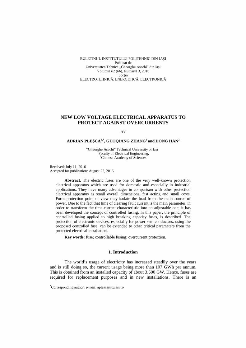
The operating of the nowadays fuse is in concordance of its time-current characteristic: at some value of the overload or shortcircuit, the fuse will interrupt the main circuit during a certain time-period. But, because of manufacturing processes, aging or inadequate operation in the main circuit, the fuse doesn’t work properly, actually at the same fault current, the operating time will be shorter or longer with respect to the appropriate value from protection characteristic. Hence, in order to avoid this unpleasant situation, it has been considered the fuse operation at a certain command depending on the value of the fault current, actually the controlled fusing effect. Therefore, on the fuse element F of the high breaking capacity fuse, Fig. 1, is placed an electrode E which is in connection with the movable contact Cd (Pleşca, 2002).
Fig. 1 – The principle of the controlled fusing effect.
The basic idea is to interrupt the fuse link F through an electric arc
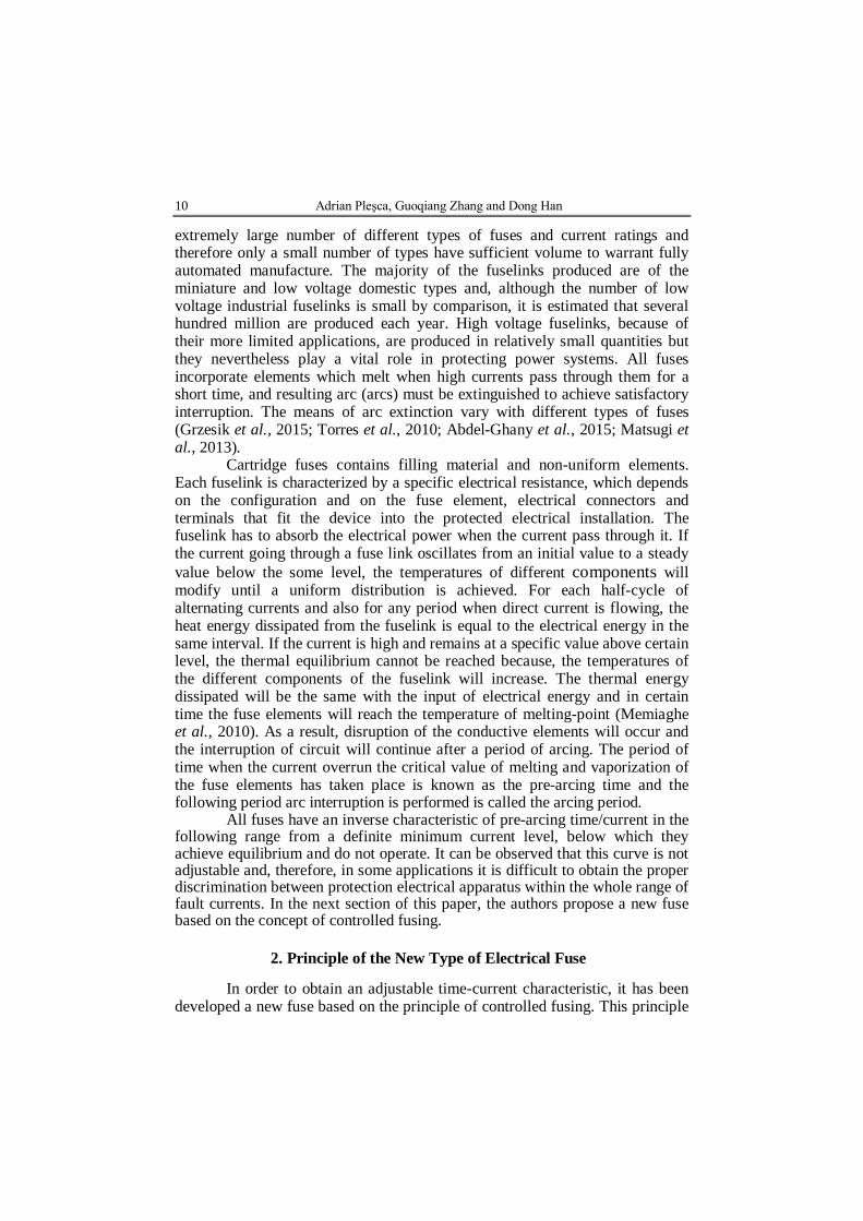
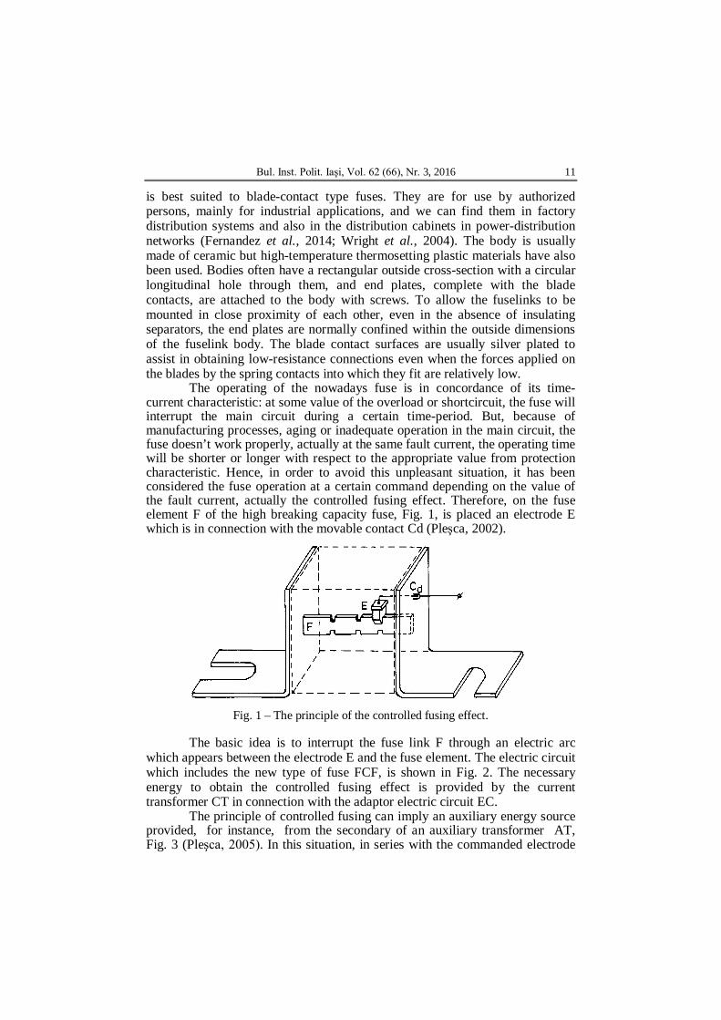
which appears between the electrode E and the fuse element. The electric circuit which includes the new type of fuse FCF, is shown in Fig. 2. The necessary energy to obtain the controlled fusing effect is provided by the current transformer CT in connection with the adaptor electric circuit EC.
The principle of controlled fusing can imply an auxiliary energy source provided, for instance, from the secondary of an auxiliary transformer AT, Fig. 3 (Pleşca, 2005). In this situation, in series with the commanded electrode
12 Adrian Pleşca, Guoqiang Zhang and Dong Han
of the new fuse FCF, there is a switch SW controlled by the electronic circuit EC. This module is supplied by the secondary of the current transformer CT.
Fig. 2 – The electric circuit with controlled fuse. Fig. 3 – The electric circuit with controlled fuse based on auxiliary power.
3. Experimental Tests
In order to check the proposed principle of controlled fusing to be
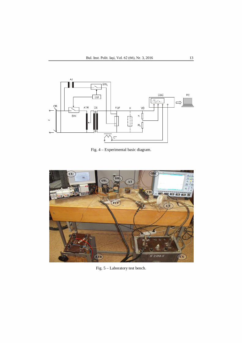
applied at high breaking capacity fuses, some experimental investigations have been performed. The basic diagram is presented in Fig.4 and a photo with the experimental set-up is shown in Fig. 5. The switch SW1 through the main circuit breaker CB, supplies the autotransformer ATR which provides an adjustable voltage on the primary side of the current source CS. On the secondary side of this electromagnetic device we can obtain adjustable high currents in order to perform experimental tests for both classical F and new FCF fuses. The power for the electrode of the controlled fuse, is obtained from the secondary of the auxiliary transformer AT through the electronic switch SW2. The experimental investigations have been performed in the case of the fuse with rated current of 63 A, gG operating class, rated voltage of 660 V and the maximum current provided by the auxiliary power in the case of controlled fusing, has been about 12A. In the following, are depicted the recorded waveforms for the arc voltage and arc current when the tested current was about 965A, in the case of classical fuse, Fig. 6, and also for the modified fuse, Fig. 7.
More, it has been computed the Joule integral variation for both type of fuses, the classical and modified one, Fig. 8.
Bul. Inst. Polit. Iaşi, Vol. 62 (66), Nr. 3, 2016 13
Fig. 4 – Experimental basic diagram.
Fig. 5 – Laboratory test bench.

14 Adrian Pleşca, Guoqiang Zhang and Dong Han
Fig. 6 – The arc voltage variation and the arc current variation in the case of classic fuse for a current of 965A rms.
Fig. 7 – The arc voltage variation and the arc current variation in the case of modified fuse for a current of 965A rms.
-0.02 -0.015 -0.01 -0.005 0 0.005 0.01 0.015 0.02-400
-200
0
200
400
t[s]
U[V
]Tensiunea de arc
-0.02 -0.015 -0.01 -0.005 0 0.005 0.01 0.015 0.02-2000
-1000
0
1000
2000
3000
t[s]
I[A]
Variaţia curentului
-0.02 -0.015 -0.01 -0.005 0 0.005 0.01 0.015 0.02-400
-200
0
200
400
t[s]
U[V
]
Tensiunea de arc
-0.02 -0.015 -0.01 -0.005 0 0.005 0.01 0.015 0.02-2000
-1000
0
1000
2000
3000
t[s]
I[A]
Variaţia curentului
Bul. Inst. Polit. Iaşi, Vol. 62 (66), Nr. 3, 2016 15
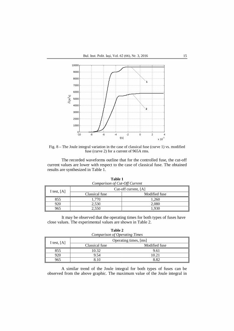
Fig. 8 – The Joule integral variation in the case of classical fuse (curve 1) vs. modified fuse (curve 2) for a current of 965A rms.
The recorded waveforms outline that for the controlled fuse, the cut-off
current values are lower with respect to the case of classical fuse. The obtained results are synthesized in Table 1.
Table 1
Comparison of Cut-Off Current
I test, [A] Cut-off current, [A] Classical fuse Modified fuse
855 1,770 1,260 920 2,530 2,080 965 2,550 1,930
It may be observed that the operating times for both types of fuses have
close values. The experimental values are shown in Table 2.
Table 2 Comparison of Operating Times
I test, [A] Operating times, [ms] Classical fuse Modified fuse
855 10.32 9.61 920 9.54 10.21 965 8.10 8.82
A similar trend of the Joule integral for both types of fuses can be
observed from the above graphic. The maximum value of the Joule integral in
-10 -8 -6 -4 -2 0 2 4
x 10-3
0
1000
2000
3000
4000
5000
6000
7000
8000
9000
10000
t[s]
I2 t[A
2 s]
1
2

16 Adrian Pleşca, Guoqiang Zhang and Dong Han
the case of modified fuse is lower than the classical one. This leads to a better effect in the case of power semiconductor devices protection because the Joule integrals condition is better satisfied.
Further on, the arc voltage and current waveforms and also Joule integral graphics for both types of fuses in the case of 30º el. phase angle of the voltage supply are shown from Figs. 9,…,11. The experimental tests have been done at 0, 30, 60, 90, 120 and 150º el. for a test current of 860 A rms.
Fig. 9 – The arc voltage and the arc current variation in the case of classic fuse.
Fig. 10 – The arc voltage and the arc current variation in the case of modified fuse.
-0.01 -0.005 0 0.005 0.01 0.015 0.02 0.025 0.03-400
-200
0
200
400
t[s]
U[V
]
Tensiunea de arc
-0.01 -0.005 0 0.005 0.01 0.015 0.02 0.025 0.03-1000
0
1000
2000
3000
t[s]
I[A]
Variaţia curentului
-0.015 -0.01 -0.005 0 0.005 0.01 0.015 0.02 0.025-400
-200
0
200
400
t[s]
U[V
]
Tensiunea de arc
-0.015 -0.01 -0.005 0 0.005 0.01 0.015 0.02 0.025-1000
0
1000
2000
3000
t[s]
I[A]
Variaţia curentului
Bul. Inst. Polit. Iaşi, Vol. 62 (66), Nr. 3, 2016 17
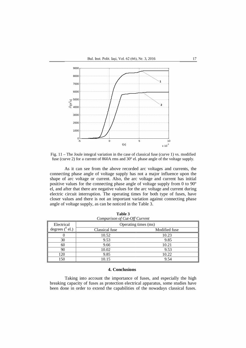
Fig. 11 – The Joule integral variation in the case of classical fuse (curve 1) vs. modified fuse (curve 2) for a current of 860A rms and 30º el. phase angle of the voltage supply.
As it can see from the above recorded arc voltages and currents, the
connecting phase angle of voltage supply has not a major influence upon the shape of arc voltage or current. Also, the arc voltage and current has initial positive values for the connecting phase angle of voltage supply from 0 to 90º el, and after that there are negative values for the arc voltage and current during electric circuit interruption. The operating times for both type of fuses, have closer values and there is not an important variation against connecting phase angle of voltage supply, as can be noticed in the Table 3.
Table 3 Comparison of Cut-Off Current
Electrical degrees (0 el.)
Operating times (ms) Classical fuse Modified fuse
0 10.52 10.23 30 9.53 9.85 60 9.66 10.21 90 10.02 9.53 120 9.85 10.22 150 10.15 9.54
4. Conclusions
Taking into account the importance of fuses, and especially the high
breaking capacity of fuses as protection electrical apparatus, some studies have been done in order to extend the capabilities of the nowadays classical fuses.
-5 0 5 10
x 10-3
0
1000
2000
3000
4000
5000
6000
7000
8000
9000
t[s]
I2 t[A
2 s]
1
2

18 Adrian Pleşca, Guoqiang Zhang and Dong Han
Hence, the proposed new principle of the controlled fusing would lead to a new type of fuse with the following advantages:
a) fuses efficiency can be increased through changes to the replacement components without changing manufacturing technology;
b) time-current characteristic can be made adjustable within certain range;
c) the protection using fuses can be extended to other critical parameters from the protected installation;
d) adopting the new principle of controlled fusing, the protection of the electrical installations can be coordinated using programmable logic controllers.
Part of research from this article was presented at the 2016 International Conference and Exposition on Electrical and Power Engineering, EPE2016, event organized by the Faculty of Electrical Engineering, "Gheorghe Asachi" Technical University of Iaşi.
REFERENCES
Abdel-Ghany H.A., Azmy A,M, Elkalashy N.I., Rashad E.M., Optimizing DG Penetration in Distribution Networks Concerningprotection Schemes and Technical Impact, Electr Pow Syst Res, 128, 113-122 (2015).
Balyberdin L.L., D’yachkov V.A., Kapitula Y.V., Lozinova N.G., DC Multimodule Fuses, Power Technology and Engineering, 45, 1, 58-61 (2011).
Dorp J. vom, Berberich S.E., Bauer A.J., Ryssel H., Analysis of the DC-Arc Behavior of a Novel 3D-Active Fuse, Solid-State Electron, 53, 809-813 (2009).
Fernandez E., Torres E., Zamora I., Mazon A.J., Albizu I., Thermal Model for Current Limiting Fuses Installed in Vertical Position, Electr Pow Syst Res, 107, 167- 174 (2014).
Grzesik M., Bailey R., Mahan J., Ampe J., Development of Fuses for Protection of Geiger-Mode Avalanche Photodiode Arrays, J. of Electron Mater, 44, 11, (2015).
Matsugi K., Saki Y., Choi Y.B., Sasaki G., Suetsugu K.I., Fujii K., Control of Electrical and Thermal Properties on Sn50Zn Alloy by 8 vol% Al2O3 Addition for Pb-Free AC-Low Voltage Fuse Elements, Mater Trans, 54, 2, 231-237 (2013).
Memiaghe S., Bussiere W., Rochette D., et al., Simulations And Measurements of the Pre-Arcing Times in HBC Fuses under Typical Electric Faults, High Temp Mater P-us, 14, 3, 255-270 (2010).
Pleşca A.T., Siguranţă fuzibilă modulară pentru protecţia instalaţiilor cu semiconductoare, Brevet RO.117953/30.09.2002.
Pleşca A.T., Dispozitiv de protecţie la supracurenţi pentru redresoare de putere necomandate, Brevet RO.117824/30.07.2002.
Pleşca A.T., Dispozitiv de protecţie pentru semiconductoare de putere, Brevet RO.117882/30.08.2002.
Pleşca A.T., Siguranţă ultarapidă specială pentru protecţia semiconductoarelor de putere, Brevet RO.120108/30.08.2005.
Pleşca A.T., Element de înlocuire specializat pentru siguranţe fuzibile cu mare putere de rupere, Brevet RO.120107/30.08.2005.
Pleşca A.T., Leonte, P., Siguranţă fuzibilă specială pentru redresoarele de putere, Brevet RO.120436/30.01.2006.
Bul. Inst. Polit. Iaşi, Vol. 62 (66), Nr. 3, 2016 19
Siyuan L., Yi Y., Haoran W. et al., DC Current Interruption by a Combination of Electric Fuse and Vacuum Switch, 3rd Internat. Conf. on Electric Power Equipment Switching Technol., ICEPE-ST 2015, Busan, South Korea, Oct 25-28.
Torres E., Mazón A.J., Fernández E., Zamora I., Pérez J.C., Thermal Performance of Back-Up Current-Limiting Fuses, Electr Pow Syst Res, 80, 1469-1476 (2010).
Wright A., Newbery P.G., Electric Fuses, Ed. IEE, London, 2004.
UN NOU TIP DE APARAT ELECTRIC DE JOASĂ TENSIUNE PENTRU PROTECŢIA ÎMPOTRIVA SUPRACURENŢILOR
(Rezumat)
Siguranţele fuzibile reprezintă unele dintre cele mai răspândite aparate electrice
de protecţie, utilizate mai ales în aplicaţii industriale. Acestea deţin o serie de avantaje în comparaţie cu alte aparate electrice de protecţie, cum ar fi dimensiuni mici, acţionare rapidă şi costuri scăzute. Datorită faptului că unul dintre parametrii principali ai siguranţelor fuzibile îl reprezintă timpul de funcţionare, s-a încercat realizarea caracteristicii de protecţie într-o manieră reglabilă. În această lucrare se descrie principiul fuziunii controlate aplicat la o siguranţă electrică de mare putere de rupere. Protecţia dispozitivelor semiconductoare de putere folosind siguranţe cu fuziune controlată, poate fi extinsă şi la alţi parametrii critici din cadrul instalaţiei electrice protejate.