Embed Size (px)
Citation preview
Datasheet Revision 3.4 April Page 1 of 20 Copyright LPRS 2011 .
Low Power Radio Solutions Ltd
Data Sheet
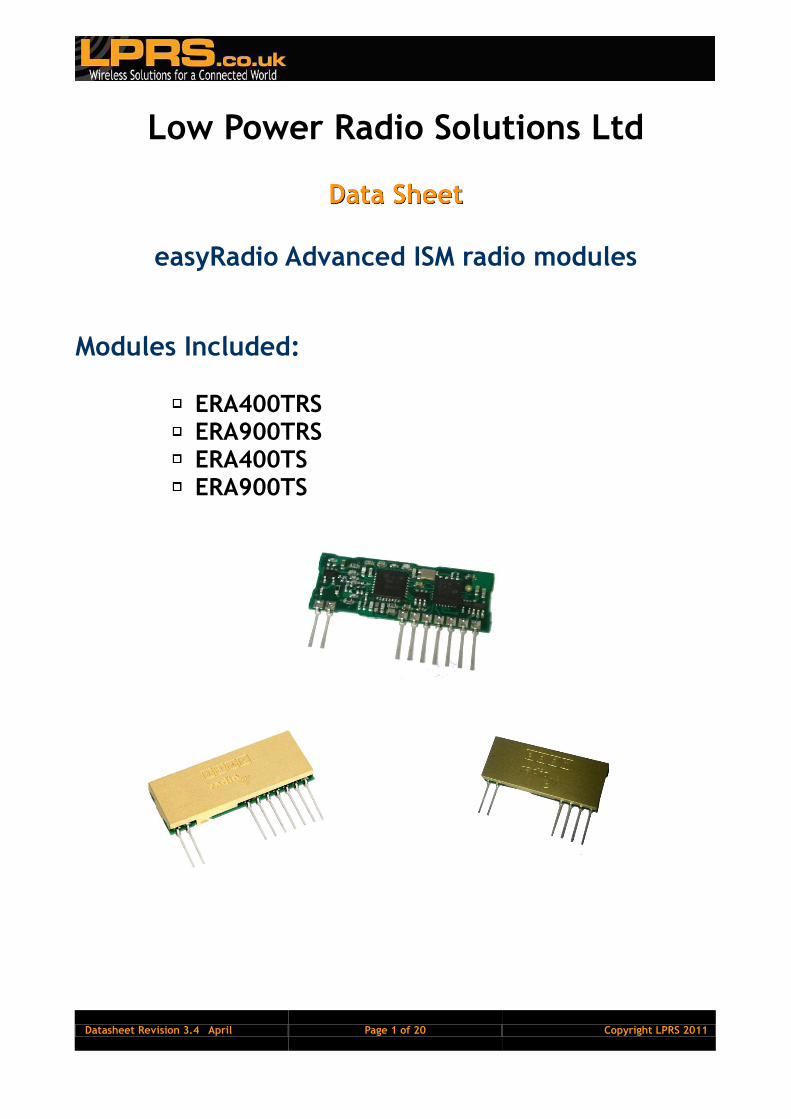
easyRadio Advanced ISM radio modules
Modules Included:
ERA400TRS ERA900TRS ERA400TS ERA900TS

Datasheet Revision 3.4 April Page 2 of 20 Copyright LPRS 2011 .
Contents
Changes to this document ................................................................................. 4
Terms and Conditions of Use ............................................................................... 4
Introduction to easyRadio Advanced ........................................................................ 5
New features: ............................................................................................... 5
Basic Specifications ........................................................................................ 5
ERA400TRS/ERA900TRS Transceiver Description .......................................................... 6
Easy-Radio Transceiver Block Diagram ................................................................... 6
Physical Dimensions ........................................................................................ 7
Pin Description (RAW RF Data mode) .................................................................... 8
ERAx00TS Transmitter ...................................................................................... 9
Block Diagram ............................................................................................... 9
Physical Dimensions ........................................................................................ 9
Pin Description .............................................................................................. 9
Application & Operation ERx00TRS-03 ..................................................................... 10
Typical System Block Diagram ............................................................................ 10
Timing Specifications – Applies to all EasyRadio Advanced Modules. ............................... 10
Absolute Maximum Ratings ERA400TRS & ERA900TRS.................................................... 11
Performance Data: ERAxxxTRS Supply +5.0 Volt ± 5%, Temperature 20° C ........................ 11
ERA400TRS Channel Frequencies vs Bandwidth Settings ................................................ 12
easyRadio Configuration Command Set .................................................................... 13
RS232 Communication Settings ........................................................................... 13
RF POWER Settings ......................................................................................... 13
RF Channel Settings ........................................................................................ 14
Bandwidth ................................................................................................... 14
Band Plan .................................................................................................... 14
MISCELLANEOUS COMMANDS .............................................................................. 14
TEST MODES ................................................................................................. 15
RAW Data Mode (TRS Only at time of print) ............................................................... 16
Notes: ........................................................................................................... 17
RSSI ........................................................................................................... 17
PCB Layout .................................................................................................. 17
Power Supply ................................................................................................ 18
Antennas ..................................................................................................... 18
Product Order Codes .......................................................................................... 18
easyRadio Advanced Module Firmware Version ........................................................... 19

Datasheet Revision 3.4 April Page 3 of 20 Copyright LPRS 2011 .
Document History ............................................................................................. 19
Copyright ....................................................................................................... 19
Disclaimer ...................................................................................................... 19
CONTACT INFORMATION ...................................................................................... 20

Datasheet Revision 3.4 April Page 4 of 20 Copyright LPRS 2011 .
Changes to this document
This data sheet has been updated to reflect firmware changes throughout the range of modules. Specific alterations are recorded in the documentation history later in the document.
Terms and Conditions of Use
Low Power Radio Solutions Ltd has an on-going policy to improve the performance and reliability of their products; we therefore reserve the right to make changes without notice. The information contained in this data sheet is believed to be accurate however we do not assume any responsibility for errors or any liability arising from the application or use of any product or circuit described herein. This data sheet neither states nor implies warranty of any kind, including fitness for any particular application. easyRadio modules are a component part of an end system product and should be treated as such. Testing to fitness is the sole responsibility of the manufacturer of the device into which easyRadio products are fitted, and is expected BEFORE deployment into the field. Any liability from defect or malfunction is limited to the replacement of product ONLY, and does not include labour or other incurred corrective expenses.
Using or continuing to use these devices hereby binds the user to these terms.

Datasheet Revision 3.4 April Page 5 of 20 Copyright LPRS 2011 .
Page 5 of 20 Page 5 of 20 Copyright LPRS 2011 .
Copyright LPRS 2011 . Page 5 of 20 Copyright LPRS 2011 .
Introduction to easyRadio Advanced
easyRadio Advanced (ERA) modules extend on the simplicity of previous easyRadio(02) modules by incorporating truly innovative features, including the ability to change bandwidth of the radio from 19.2KHz down to 12.5KHz, which means narrow-band performance on a wide-band budget. Internal temperature measurement ensures less than 1.5KHz frequency drift from ambient 20°C, over a range of -40°C to +85°C, as well as providing a usable thermometer for the connected application accurate to within 1°C. Modes of transmission include an enhanced easyRadio protocol with 16-bit encryption and anti-cross talk software, plus raw data modes where users can now use self-coding system which can be set to interface to any other raw data module on ISM bands in both FSK (FM) and ASK (AM) modulation. With the addition of three (total 4) separate data buffers, data throughput has been massively improved by around 25%*.
New features:
A new digital RSSI (Received Signal Strength Indication) now reduces the requirement for the host to handle A-D measurement and can be called via a simple command for either the current RSSI level or the signal strength of the last received data packet. This value can also be delivered as the first BYTE in the delivered packet.
Temporary channel/power level selection: This new command allows the user to scan other channels without storing the settings in internal EEPROM, therefore not reducing the life of the EEPROM through repetitive modification.
Free flash firmware upgrades. Using the tools from LPRS, new updates/features can be quickly programmed making a truly future proof solution. Custom firmware can also be used (Contact LPRS for details)
Back compatibility with 02 modules.
Temperature compensation plus crystal controlled synthesiser for frequency accuracy less than +/- 1KHz over full temperature range
Temperature sensor usable by host
Basic Specifications
High sensitivity receiver o -107dBm @ 19.2 Kbps o -112dBm @ 4.8 Kbps o -117dBm @ 2.4 Kbps
Current o Receiver: 21mA (Max) o Transmitter: 32mA (Max)
User Programmable: Frequency (Up to 132 channels) Bandwidth (Down to 12.5KHz) RS232 Data Rate Output Power (Up to 10dBm)
10mW @ 434MHz 5mW @ 869.85MHz

Datasheet Revision 3.4 April Page 6 of 20 Copyright LPRS 2011 .
Page 6 of 20 Page 6 of 20 Copyright LPRS 2011 .
Copyright LPRS 2011 . Page 6 of 20 Copyright LPRS 2011 .
ERA400TRS/ERA900TRS Transceiver Description The easyRadio Transceiver is a complete sub-system that combines a high performance very low power RF transceiver, a microcontroller and a voltage regulator:
easyRadio Transceiver Block Diagram
The Serial Data Input and Serial Data Output operate at the standard 19,200 Baud and the two handshake lines provide optional flow control to and from the host. The easyRadio Transceiver can accept and transmit up to 180 bytes of data, which it buffers internally before transmitting in an efficient over-air code format. Any other easyRadio Transceiver within range and on the same channel that „hears‟ the transmission will decode the message and place the recovered data within a receive buffer that can then be downloaded to the receiving host for processing and interpretation. Radio transmission and reception is bi-directional (half duplex) i.e. transmit OR receive but not simultaneously. Increased internal buffers however, allow the user to upload while a download is in progress giving an appearance of fully duplex data flow.
μ P
rocessor
RFIC
3.3vRegulator
Vcc (Pin 8)
Carrier Detect (Pin 3)
BUSY (Pin 4)
TemperatureSensor
EEPROM Ready (Pin 7)
Serial Data In (Pin 6)
Serial Data Out (Pin 5)
Ground (Pins 2 & 9)

Datasheet Revision 3.4 April Page 7 of 20 Copyright LPRS 2011 .
Page 7 of 20 Page 7 of 20 Copyright LPRS 2011 .
Copyright LPRS 2011 . Page 7 of 20 Copyright LPRS 2011 .
Physical Dimensions
Pin Description (easyRadio mode)
Pin No Name Description Notes
1 Antenna 50Ω RF input/output. Connect to suitable antenna.
2 RF Ground
RF ground. Connect to antenna ground (coaxial cable screen braid) and local ground plane. Internally connected to other Ground pins.
3 CD Carrier Detect
4 Busy Output Digital Output to indicate that transceiver is ready to receive serial data from host.
CTS function
5 Serial Data Out Digital output for received data to host
6 Serial Data In Digital input for serial data to be transmitted
7 Host Ready Input Digital Input to indicate that Host is Ready to receive serial data from transceiver
RTS function
8 Vcc
Positive supply pin. +2.5 to +5.5 Volts. This should be a „clean‟ noise free supply with less than 25mV of ripple.
9 Ground Connect to supply 0 Volt and ground plane
ERA400TRSERA900TRS
Pin Pitch 2.54mmPCB Hole Size 1.0mm
1 2 3 4 5 6 7 8 9
38.0 mm1
4.0
mm
10
.0 m
m
15.24 mm
4.0 mm

Datasheet Revision 3.4 April Page 8 of 20 Copyright LPRS 2011 .
Page 8 of 20 Page 8 of 20 Copyright LPRS 2011 .
Copyright LPRS 2011 . Page 8 of 20 Copyright LPRS 2011 .
Checklist
1. The module operates internally from an on board 3.3 Volt low drop regulator. The logic levels of the input/output pins are therefore between 0 Volt and 3.3 Volts. (See specifications/performance data).
2. The serial inputs and outputs are intended for connection to a UART or similar low voltage logic device. Do not connect any of the inputs or outputs directly to an RS232 port. The transceiver module may be permanently damaged by the voltages (+/- 12V) present on RS232 signal lines. See Application Circuit (Figure 11) for typical connection to an RS232 port via MAX232 interface IC.
3. The „Host Ready Input‟ should be tied to 0 Volt (Ground) if not used, only when handshaking is enabled.
4. Outputs will drive logic operating at 3.3 Volts and inputs will be correctly driven by logic operating at 5 Volts.
5. Fit 1K resistors in series with data lines if connecting to 5V logic.
Pin Description (RAW RF Data mode)
Pin No Name Description Notes
1 Antenna 50Ω RF input/output. Connect to suitable antenna.
2 RF Ground RF ground. Connect to antenna ground (coaxial cable screen braid) and local ground plane. Internally connected to other Ground pins.
3 CD/Config Carrier Detect Carrier Detect/Config mode select pin
4 RX Select RX mode select pin Active Low
5 RX Data Raw RF data output
6 TS Data Raw RF data Input (Toggling this pin modulates the carrier)
7 TX Select Enables the transmitter carrier.
Active Low
8 Vcc Positive supply pin. +2.5 to +5.5 Volts. This should be a „clean‟ noise free supply with less than 25mV of ripple.
9 Ground Connect to supply 0 Volt and ground plane

Datasheet Revision 3.4 April Page 9 of 20 Copyright LPRS 2011 .
Page 9 of 20 Page 9 of 20 Copyright LPRS 2011 .
Copyright LPRS 2011 . Page 9 of 20 Copyright LPRS 2011 .
ERAx00TS Transmitter
Block Diagram
Physical Dimensions
Pin Description
Pin N Name Description Notes
1 RF Gnd RF ground. Connect to antenna ground (coaxial cable screen braid) and local ground plane. Internally connected to Pin 5
2 RF Out 50Ω RF output. Connect to suitable antenna
3 Serial Data Out RS232 Output for Command use (SDO)
4 Vcc Positive supply pin. +2.5 to +5.5 Volts. This should be a „clean‟ noise free supply with less than 25mV of ripple
5 Gnd Supply 0 Volt and Ground Plane
6 TXD RS232 Transmit Data Digital Input (SDI)
Notes:
1. The module operates internally from an on board 3.3 Volt low drop regulator. 2. TXD input will be correctly driven by logic operating at 2.5 - 5 Volts. Input should not be driven by
an analogue source.
μ P
rocessor
RFICTransmitter
3.3vRegulator
Vcc (Pin 4)
TemperatureSensor
EEPROM
Serial Data In (Pin 6)
Serial Data Out (Pin 3)
Ground (Pins 2 & 5)
ERA400TSERA900TS
1 2 3 4 5 6
4.0 mm
17.78mm
31.0 mm
12
.0 m
m
Pin Pitch 2.54mmPCB Hole Size 1.0mm

Datasheet Revision 3.4 April Page 10 of 20 Copyright LPRS 2011 .
Page 10 of 20 Page 10 of 20 Copyright LPRS 2011 .
Copyright LPRS 2011 . Page 10 of 20 Copyright LPRS 2011 .
Application & Operation ERx00TRS-03 The diagram below shows a typical system block diagram comprising hosts (user‟s application) connected to easyRadio Transceivers. The hosts (A & B) will be monitoring (collecting data) and/or controlling (sending data) to some real world application.
Easy-Radio
Transceiver
(A)
Host
(A)
Serial Data Input
Serial Data Output
Host Ready
Busy
Easy-Radio
Transceiver
(B)
Host
(B)
Serial Data Input
Serial Data Output
Host Ready
Busy
RF Link
Typical System Block Diagram
The hosts provide serial data input and output lines and two „handshaking‟ lines that control the flow of data to and from the easyRadio Transceivers. The „Busy‟ output line, when active, indicates that the transceiver is undertaking an internal task and is not ready to receive serial data. The „Host Ready‟ input is used to indicate that the host is ready to receive the data held in the buffer of the easyRadio Transceiver. The host should check before sending data that the „Busy‟ line is not high, as this would indicate that the transceiver is either transmitting or receiving data over the radio link. It should also pull the „Host Ready‟ line low and check that no data appears on the Serial Data Output line.
Timing Specifications – Applies to all easyRadio Advanced Modules.
Host Serial Input/Output 2400, 4800, 9600, 19200, 38400, 31250 (MIDI), 76800 & 115200
baud 1
Host Character Format 1 Start, 8 Data, No Parity, 1 Stop
Bits 2
End of Data Delay 2 x BAUD BYTE Duration mS 3
RF Transmit Depends on Bandwidth mS 4
Buffer Size 1-180 Bytes 5
Notes
1. Data is inverted i.e. Start Bit is logic low. The inputs are intended for direct connection to a microcontroller UART or to RS232 inputs and outputs via an RS232 Level translator such as a Maxim MAX232, which invert the logic of the RS232 signals. This allows direct connection to, for example a Microcontroller UART. The data rate is user programmable (Default 19200 baud) and may differ between individual units within a system. (See Application Circuit diagram for logic level to RS232 interface figure 11).
2. 1 start, 8 data, 1 stop = 10 bits @ 104uS/bit = 0.52mS/character at 19200 Baud. (Default) 3. The „End of Data‟ delay is fixed at twice the character time. 4. A fixed package overhead of xx is added to all packets. 5. The buffer size is limited to 180 bytes. Sending more than 180 bytes will cause loss of data.
a. CTS pin will go high 2 bytes before the buffer is full. This allows characters already sent to be accepted by the ER module.

Datasheet Revision 3.4 April Page 11 of 20 Copyright LPRS 2011 .
Page 11 of 20 Page 11 of 20 Copyright LPRS 2011 .
Copyright LPRS 2011 . Page 11 of 20 Copyright LPRS 2011 .
Absolute Maximum Ratings ERA400TRS & ERA900TRS Operating Temperature Range -40° C to +85° C Storage Temperature Range -40° C to +85° C Vcc - 0.3 to + 6 Volts All Other Pins (N.B.) - 0.3 to 3.3 Volts Antenna 50V p-p @ < 10MHz Must be insulated to prevent
damage from ESD
Performance Data: ERAxxxTRS Supply +5.0 Volt ± 5%, Temperature 20° C
DC Parameters Pin Min Typical Max Units Notes
Supply Voltage (Vcc)
8 2.5 3.3-5.0 5.5 Volts
Transmit supply current
8 32 33 mA
Receive supply current
8 21 mA
Sleep Mode current 8 800 µA
Interface Levels
Data Output Logic 1 3.1 Volts 10k load to +Vcc supply
Data Output Logic 0 0.1 Volts 10k load to +Vcc supply
Logic Output Current
25 mA
Data Input Logic 1 2.0 3.6 Volts
Data Input Logic 0 0.2 Volts
Input Pull-ups 100 KΩ 1
RF Parameters Pin Min Typical Max Units Notes
Antenna Impedance 1 50 Ohms
RF Frequency 402 868 902
434 869.85
915
470 870 928
MHz MHz MHz
See ER Configuration Command set
Transmitter
RF Power Output 1 -5 -5
+9 +5
+10 +5
dBm (434MHz)
dBm (869MHz)
50Ω load Depends on Frequency
Frequency accuracy ±2 ppm Overall
FM deviation 9.9 2.4
2.025
Khz Khz KHz
100KHz Spacing 25KHz Spacing
12.5KHz Spacing
Harmonics/ Spurious Emmissions
-47 < -36 dBm Meets EN 300 220-3
Over Air Data rate 1200 19200 38400 bps Manchester Encoded
Receiver
Receive Sensitivity -107 -117
dBm dBm
At 100KHz Channel Spacing At 12.5KHz Channel Spacing
Serial Data Rate 2.4 19.2 115.2 Kbps Host interface. 6

Datasheet Revision 3.4 April Page 12 of 20 Copyright LPRS 2011 .
Page 12 of 20 Page 12 of 20 Copyright LPRS 2011 .
Copyright LPRS 2011 . Page 12 of 20 Copyright LPRS 2011 .
Logic Timing Pin Min Typical Max Units Notes
Initial Power Up Time
5 75 mS 2,3
Mechanical
Size 38 x 14 x 4 mm
Pin Pitch 2.54 mm (Standard 0.1 Inches)
Weight 3.5 gms
Notes
1. The „Host Ready Input‟ and the „Serial Data Input‟ have „weak‟ internal pull-ups enabled. 2. When power is first applied to the module the processor retrieves „calibration‟ data for the RF
section that compensates for temperature and power supply voltage variations. The transceiver will then be ready to receive (default) or transmit. It would normally be left in this powered state ready to receive data.
3. During power up the Busy Output line goes high and goes low once ready.
ERA400TRS Channel Frequencies vs Bandwidth Settings Each channel frequency is calculated relative to the channel number, the channel width, and the start frequency of the channel. Three commands control the settings of each of these parameters: Channel command: ER_CMD#Cn - Where n is channel number (See command table) Bandwidth Command: ER_CMD#Bn - Where n is the Channel spacing Band Plan Command: ER_CMD#bn - Where n is the START frequency of the band plan being used The centre frequency of each channel is calculated using the formula:
Centre Frequency (f) = b + cs + 𝑠
2
Where b = band plan start frequency c = channel number s = channel spacing

Datasheet Revision 3.4 April Page 13 of 20 Copyright LPRS 2011 .
Page 13 of 20 Page 13 of 20 Copyright LPRS 2011 .
Copyright LPRS 2011 . Page 13 of 20 Copyright LPRS 2011 .
easyRadio Configuration Command Set The programming software sends „Text Commands‟ to the modules and this action can be performed by terminal software or the host‟s Microcontroller using the following list of commands: Note that shaded items are either new 03 commands or changes from 02 modules.
RS232 Communication Settings
ER_CMD#U1 UART Data Rate 2400 2400
ER_CMD#U2 4800 4800 ER_CMD#U3 9600 9600 ER_CMD#U4 19200 19200 ER_CMD#U5 38400 38400 ER_CMD#U6 31250 31250 ER_CMD#U7 76800 76800 ER_CMD#U8 115200 115200
ER_CMD#U? Get UART Value
The module replies echos with the UART value. Eg: ER_CMD#U2 No ACK is required.
ER_CMD#A70 PARITY DISABLE DISABLED BY DEFAULT When enabled data = 1 Start, 8 Data, 1 Parity, 1 Stop
ER_CMD#A71 EVEN PARITY ER_CMD#A72 ODD PARITY
ER_CMD#A41 FAST ACK Enable OFF OFF (Upper case i) See notes on “FAST ACK” below.
ER_CMD#A40 FAST ACK Disable
RF POWER Settings
ER400Series ER900 Series ER_CMD#P0~9 RF Power Output
ER_CMD#P? Get Power Value
The module replies with the power value. eg: ER_CMD#P9 No ACK is required.

Datasheet Revision 3.4 April Page 14 of 20 Copyright LPRS 2011 .
Page 14 of 20 Page 14 of 20 Copyright LPRS 2011 .
Copyright LPRS 2011 . Page 14 of 20 Copyright LPRS 2011 .
RF Channel Settings
ER_CMD#Cx Where x = Channel Number in Decimal
Eg Channel 5: ER_CMD#C5 or ER_CMD#C05 or ER_CMD#C005 Uppercase 'C' stores settings in EEPROM
ER_CMD#cx As Upper case C Lowercase 'c' does not store in EEPROM
ER_CMD#C? Get Channel Value The module replies echoes with the current channel. Eg: ER_CMD#C9 No ACK is required.
Bandwidth
ER_CMD#Bx X = 0 1 2 3 6
12.5KHz 25KHz 50KHz 100KHz 150KHz
2400bps 4800bps 9600bps 19200bps 02 Compatibility
After this command, the Channel number will set to Channel 0.
Band Plan ERA400 ERA900
ER_CMD#bx Default = 0 1 2 3
433.1 MHz 433.1125 MHz 458.5125 MHz 433.0 MHz
869.7MHz 902MHz 863MHz
This setting chooses the start frequency of Channel 0
MISCELLANEOUS COMMANDS
ER_CMD#R0 Reset module (POR) Power reset
ER_CMD#A00 DCS OFF (default) Recommended ON for new designs where back compatibility to older devices is not required
ER_CMD#A01 DCS ON ER_CMD#A10 Encryption OFF
(default) Encryption algorithm is created and owned solely by LPRS. It uses a 16-bit seed that can be set by the developer.
ER_CMD#A11 Encryption ON ER_CMD#A20 CRC16 OFF The CRC16 routines
are more efficient and secure than the old CRC8. For new

Datasheet Revision 3.4 April Page 15 of 20 Copyright LPRS 2011 .
Page 15 of 20 Page 15 of 20 Copyright LPRS 2011 .
Copyright LPRS 2011 . Page 15 of 20 Copyright LPRS 2011 .
applications it is recommended. All new Bandwidth settings use CRC16. This setting only applies to 02 compatibility mode.
ER_CMD#A21 CRC16 ON(default) ER_CMD#A30/1 Repeater OFF/ON NOT YET IMPLEMENTED
ER_CMD#A40/1 Fast ACK OFF/ON ER_CMD#A50/1 Handshaking OFF/ON ER_CMD#A70 ER_CMD#A71 ER_CMD#A72
Parity Disable Parity Even Parity Odd
ER_CMD#a0/1 RSSI In Packet When enabled each packet is preceded by the 8 bit RSSI value of the received packet
TEST MODES
ER_CMD#T0 Upper FSK Carrier Test Mode 0
ER_CMD#T1 Modulated Carrier Test Mode 1 With Temperature compensation
ER_CMD#T2 Lower FSK Carrier Test Mode 2
ER_CMD#T3 Get Firmware Revision
Returns Firmware String: eg ERA400TRS V3.6.23
ER_CMD#T4 RAW Data Test Out of CTS pin
ER_CMD#T5 Modulated Carrier Without Temperature compensation
ER_CMD#T7 Temperature Sensor Reply example: -15'C or 23.7'C
ER_CMD#T8 Last Packet RSSI Returns the HEX value of the RSSI register measured on the last valid packet.
ER_CMD#T9 Current RSSI Live RSSI Value
To successfully send commands do the following:
1. Send Command from host: e.g. ER_CMD#U5 (Set UART BAUD to 38400) 2. In the case of a TRS/RS:
o Wait for echo of command from module. e.g. ER_CMD#U5 1. Send the ASCII string from the host: ACK
The commands should be sent exactly as shown (case sensitive) with no spaces between characters. The ACK command is sent as three ASCII characters, ACK in sequence. „A‟‟C‟‟K‟ .

Datasheet Revision 3.4 April Page 16 of 20 Copyright LPRS 2011 .
Page 16 of 20 Page 16 of 20 Copyright LPRS 2011 .
Copyright LPRS 2011 . Page 16 of 20 Copyright LPRS 2011 .
RAW Data Mode (TRS Only at time of print) easyRadio Advanced modules have the added versatility of being used without the proprietary protocols from easyRadio and yet still being used as a multi-channel, multi-bandwidth module. This allows the user to set precise frequencies to replace other raw data devices on exact frequencies. Both FSK (FM) and ASK (AM) modes are supported, and with the integration of a configuration mode, AM/FM modes, power levels, channels and bandwidth settings, can be changed on the fly with a very efficient command structure. Enable RAW data mode:
1) When in easyRadio mode send the command ER_CMD#L40202 2) Perform a power reset with Pin 3 left either floating or held high
Return to easyRadio mode:
1) Hold Pin 3 low while providing power (This will not change the default POR setting) 2) Once powered, send the command ER_CMD#L40200. This will reset the default POR setting to
easyRadio Mode Pin 1 Antenna Pin 2 RF Ground Pin 3 Carrier Detect/Config Mode Pin Pin 4 RX Select (Active Low) Pin 5 RF RX Data Output Pin 6 TX Data Input Pin 7 TX Select (Active Low) Pin 8 VCC Pin 9 Data Ground
Mode Selection 1 = +V, 0 = 0V, x = Don’t Care
Pin 3 Pin 4 Pin 7 Mode
x 1 1 Sleep
x 0 1 RX Enabled (Output on Pin 5)
x 1 0 TX Enabled (Input Modulation on Pin 6)
1 0 0 Module asleep but higher current (Not recommended)
0 0 0 Configure mode
Once in configure mode, Pins 5 & 6 return to functional UART pins at the stored module BAUD rate (default 19200). The configuration command set ALL setting in one command which is 5 bytes long:
BYTE 1 BYTE 2 BYTE 3 BYTE 4 BYTE 5
Bandwidth/AM-FM Band Plan Channel Power Level CSUM
Each byte uses Hex values in 8-bit format and corresponds to the settings used when selecting parameters in normal ER commands. Bit 7 of BYTE 1 is used to switch between AM/FM modes. 0 = FM, 1 = AM. Therefore, to set an FM channel 10 at 12.5KHz Spacing on Band-plan 0 and power level 9: The configuration word would be: 01 00 0A 09 14 (Note CSUM at BYTE 5)
ERA400TRSERA900TRS
1 2 3 4 5 6 7 8 9

Datasheet Revision 3.4 April Page 17 of 20 Copyright LPRS 2011 .
Page 17 of 20 Page 17 of 20 Copyright LPRS 2011 .
Copyright LPRS 2011 . Page 17 of 20 Copyright LPRS 2011 .
The module will ALWAYS respond with an ERROR Status Byte:
7 6 5 4 3 2 1 0
7 6 5 4 3 2 1 0
X X PLL BW BP C P CSUM
A high in ANY of these positions indicates a failure in the Values used. Bit 5 (PLL) indicates a failure to lock frequency using the settings requested and returns the module to the previously set mode. Exit Configuration Mode: Simply return Pin 3 to the High State and once all operations are completed (After delivery of ERROR Status BYTE) the Radio will return to RAW Data Mode with the new settings.
Notes:
RSSI
The Receiver/Transceiver has a built in RSSI (Received Signal Strength Indicator) that provides a digital value relating to the power at the input. This value can be read back using the ER command “ER_CMD#T8” or can be set to deliver the value as the first byte of each packet. This value will be different, depending on the bandwidth currently in use. The graph below explains how to interpret the values:
PCB Layout
The Ground (0 Volt) pins of the receiver should be connected to a substantial ground plane (large area of PCB copper) connected to 0 Volt. It is suggested that a double sided PCB be used with one layer being the ground plane.

Datasheet Revision 3.4 April Page 18 of 20 Copyright LPRS 2011 .
Page 18 of 20 Page 18 of 20 Copyright LPRS 2011 .
Copyright LPRS 2011 . Page 18 of 20 Copyright LPRS 2011 .
Power Supply
The supply used to power the receiver should be „clean‟ and free from ripple and noise (<20mV p-p total). It is suggested that 100nF ceramic capacitors be used to de-couple the supply close to the power pins of the receiver. The use of „switch mode‟ power supplies should be avoided as they can generate both conducted and radiated high frequency noise that can be very difficult to eliminate. This noise may considerably reduce the performance of any radio device that is connected or adjacent to the supply.
Antennas
The receiver can be used with the various common types of antenna that match the 50Ω RF Input/Output such as a monopole (whip), helical or PCB/Wire loop antennas. Monopole antennas are resonant with a length corresponding to one quarter of the electrical wavelength
should be 16.4cms in length. This should be straight, in „free space‟ (kept well away from all other circuitry) and should be connected directly to the Antenna pin of the receiver. If the antenna is remote it should be connected via a 50Ω coaxial feeder cable or transmission line. A 50Ω transmission line can be constructed on FR4 board material by using a 3mm wide PCB track over a ground plane. This should be kept as short as possible. Helical antennas are also resonant and generally chosen for their more compact dimensions. They are more difficult to optimise than monopole antennas and are critical with regard to surrounding objects that can easily „de-tune‟ them. They operate most efficiently when there is a substantial ground plane for them to radiate against. Wire or PCB Loop antennas are the most compact antennas but are less effective than the other types. They are also more difficult to design and must be carefully „tuned‟ for best performance. The Internet can provide much useful information on the design of Short Range Device (SRD) Antennas.
Product Order Codes
Name Description Order Code ERA400TS UK/European Transmitter Module
on 433 MHz ERA400TS
ERA400TRS UK/European Transceiver Module
on 433 MHz ERA400TRS
ERA900TS Europe/US Transmitter Module 869/915MHZ
ERA900TS
ERA900TRS Europe/US Transceiver Module 869/915MHZ
ERA900TRS
Please contact the sales office for availability and other variants of the standard product. The software interface can be customised to specific requirements for high volume applications.

Datasheet Revision 3.4 April Page 19 of 20 Copyright LPRS 2011 .
Page 19 of 20 Page 19 of 20 Copyright LPRS 2011 .
Copyright LPRS 2011 . Page 19 of 20 Copyright LPRS 2011 .
easyRadio Advanced Module Firmware Version
Version Date Revision Known Issues
3.6.9 January 2010 Initial Release None at time of print.
3.6.17 October 2010 Improved Calibration.
3.6.23 March 2011 Numerous feature additions
RS232 Parity not yet working.
Document History
Issue Date Revision
3.1 January 2010 First Provisional Datasheet for „03‟ series modules
3.4 April 2011 Module rebranded as ERA. Numerous corrections/additions
Copyright The information contained in this data sheet is the property of Low Power Radio Solutions Ltd and copyright is vested in them with all rights reserved. Under copyright law this documentation may not be copied, photocopied, reproduced, translated or reduced to any electronic medium or machine readable form in whole or in part without the written consent of Low Power Radio Solutions Ltd. The circuitry and design of the modules are also protected by copyright law.
Disclaimer Low Power Radio Solutions Ltd has an on going policy to improve the performance and reliability of their products; we therefore reserve the right to make changes without notice. The information contained in this data sheet is believed to be accurate however we do not assume any responsibility for errors or any liability arising from the application or use of any product or circuit described herein. This data sheet neither states nor implies warranty of any kind, including fitness for any particular application. easyRadio modules are a component part of an end system product and should be treated as such. Testing to fitness is the sole responsibility of the manufacturer of the device into which easyRadio products are fitted, as is also the deployment into the field. Any liability from defect or malfunction is limited to the replacement of product ONLY, and does not include labour or other incurred corrective expenses.

Datasheet Revision 3.4 April Page 20 of 20 Copyright LPRS 2011 .
Page 20 of 20 Page 20 of 20 Copyright LPRS 2011 .
Copyright LPRS 2011 . Page 20 of 20 Copyright LPRS 2011 .
Using or continuing to use these devices hereby binds the user to these terms.
CONTACT INFORMATION
For further information or technical assistance please contact: Low Power Radio Solutions Ltd Two Rivers Industrial Estate
Station Lane Witney Oxon OX28 4BH England
Tel: +44 (0)1993 709418 Fax: +44 (0)1993 708575 Web: http://www.lprs.co.uk Email: [email protected]