Embed Size (px)
Citation preview
by
by
Gerhardus Ignatius Potgieter Veale
Submitted in partial fulfilment of the requirements for the degree
Master of Engineering (Microelectronic Engineering)
in the
Faculty of Engineering, Built Environment & Information Technology
University of Pretoria
July 2010
LOW PHASE NOISE 2 GHz FRACTIONAL-N CMOS SYNTHESIZER IC
©© UUnniivveerrssiittyy ooff PPrreettoorriiaa

Department of Electrical, Electronic and Computer Engineering P a g e | i University of Pretoria
SUMMARY
LOW PHASE NOISE 2 GHZ FRACTIONAL-N CMOS SYNTHESIZER IC
BY GERHARDUS IGNATIUS POTGIETER VEALE
Supervisor: Dr Saurabh Sinha
Department of Electrical, Electronic & Computer Engineering
Degree: M. Eng. (Microelectronic Engineering)
Low noise low division 2 GHz RF synthesizer integrated circuits (ICs) are conventionally
implemented in some form of HBT process such as SiGe or GaAs. The research in this
dissertation differs from convention, with the aim of implementing a synthesizer IC in a more
convenient, low-cost Si-based CMOS process. A collection of techniques to push towards the
noise and frequency limits of CMOS processes, and possibly other IC processes, is then one of
the research outcomes.
In a synthesizer low N-divider ratios are important, as high division ratios would amplify
in-band phase noise. The design methods deployed as part of this research achieve low
division ratios (4 ≤ N ≤ 33) and a high phase comparison frequency (>100 MHz). The
synthesizer IC employs a first-order fractional-N topology to achieve increased frequency
tuning resolution. The primary N-divider was implemented utilising current mode logic
(CML) and the fractional accumulator utilising conventional CMOS. Both a conventional
CMOS phase frequency detector (PFD) and a CML PFD were implemented for benchmarking
purposes. A custom-built 4.4 GHz synthesizer circuit employing the IC was used to validate
the research.
In the 4.4 GHz synthesizer circuit, the prototype IC achieved a measured in-band phase noise
plateau of L( f ) = -113 dBc/Hz at a 100 kHz frequency offset, which equates to a figure of
merit (FOM) of -225 dBc/Hz. The FOM compares well with existing, but expensive, SiGe and
GaAs HBT processes. Total IC power dissipation was 710 mW, which is considerably less
than commercially available GaAs designs. The complete synthesizer IC was implemented in
Department of Electrical, Electronic and Computer Engineering P a g e | ii University of Pretoria
Austriamicrosystems’ (AMS) 0.35 µm CMOS process and occupies an area of
3.15 x 2.18 mm2.
Keywords:
Fractional-N, low division, SSB phase noise, CML, CML 2/3-Prescaler, pulse-swallow
counter, CML 4-bit counter, CML PFD, CMOS PFD, CML-to-CMOS converter, in-band
phase noise, CML flicker noise, high voltage charge-pump, programmable modulus
accumulator

Department of Electrical, Electronic and Computer Engineering P a g e | iii University of Pretoria
SAMEVATTING
LAE FASE-RUIS 2 GHZ FRAKSIONELE-N CMOS-SINTETISEERDER
DEUR GERHARDUS IGNATIUS POTGIETER VEALE
Toesighouer: Dr Saurabh Sinha
Departement Elektriese, Elektroniese en Rekenaar-ingenieurswese
Graad: M. Ing. (Mikroëlektroniese Ingenieurswese)
Lae faseruis en lae deeltal 2 GHz RF-sintetiseerder geïntegreerde stroombane is tradisioneel in
HBT-prosesse soos SiGe of GaAs geïmplementeer. Die navorsing in hierdie verhandeling wyk
af van konvensie deur ’n CMOS-sintetiseerderimplementering. Si-gebaseerde CMOS-prosesse
is sowel goedkoper as meer algemeen. Een van die verhandeling se uitsette is ’n versameling
tegnieke wat die ruis- en frekwensielimiete van CMOS-prosesse aanspreek. Hierdie metodes
kan waarskynlik ook vir ander geïntegreerde stroombaanprosesse gebruik word.
In ’n sintetiseerder is lae N-deelsyfers belangrik, aangesien hoë deelsyfers die binnebandfase-
ruis sal versterk. Ontwerpmetodes wat deel vorm van die navorsing behaal lae deeltalle
(4 ≤ N ≤ 33) en ’n hoë fasevergelykingsfrekwensie (>100 MHz). ’n Eerste-orde fraksionele-N
sintetiseerdertopologie is gerealiseer vir uitgebreide frekwensie verstelbaarheid. Die hoof
N-deler is geïmplementeer in stroommoduslogika (SML) en die fraksionele akkumulator in
konvensionele CMOS. Sowel ’n konvensionele CMOS-fasefrekwensie-vergelyker (FFV) as ’n
SML FFV is geïmplementeer en met mekaar vergelyk. ’n 4.4 GHz sintetiseerdertoetsbaan is
gebou om die geïntegreerde stroombaan prakties te meet.
In die 4.4 GHz toetsbaan is ’n binne-band faseruisvloer gemeet van L( f ) = -113 dBc/Hz teen
’n frekwensie-afset van 100 kHz. Hierdie syfer transleer na ’n -225 dBc/Hz syfer van meriete
wat goed vergelyk met bestaande en duurder SiGe- en GaAs-prosesse. Die totale
drywingsverbruik is 710 mW, maar dit is heelwat minder as bestaande kommersiële GaAs-

Department of Electrical, Electronic and Computer Engineering P a g e | iv University of Pretoria
ontwerpe. Die voltooide geïntegreerde stroombaan is vervaardig volgens Austriamicrosystems
(AMS) se 0.35 µm CMOS-proses en beslaan ’n area van 3.15 x 2.18 mm2.
Sleutelwoorde:
Fraksionele-N, lae deeltal, ESB-faseruis, SML, SML 2/3-voordeler, puls-slukteller, SML
4-bis-teller, SML FFV, CMOS FFV, SML-na-CMOS-omsetter, binne-band faseruis, SML-
flikkerruis, hoëspanning-stroompomp, programmeerbare modulusakkumulator
Department of Electrical, Electronic and Computer Engineering P a g e | v University of Pretoria
ACKNOWLEDGEMENTS
I would like to thank several persons and organisations who helped and were involved during
the research and writing of this dissertation.
My supervisor, Dr Saurabh Sinha, for his support and availability during the entire
process.
Grintek Ewation (Pty) Ltd (GEW) for funding the layout and manufacturing of the
evaluation printed circuit board (PCB).
Jan Roux for laying out the evaluation PCB.
Jannes Venter for his invaluable support on all the CAD tools provided by the Carl and
Emily Fuchs Institute for Microelectronics (CEFIM).
My wife Adri for her support during this dissertation.
This dissertation would also not have been possible without the grace of God and His
faithfulness.

Department of Electrical, Electronic and Computer Engineering P a g e | vi University of Pretoria
TABLE OF CONTENTS
Chapter 1: Introduction................................................................................................................1
1.1 Motivation.....................................................................................................................1
1.2 Justification for the research .........................................................................................2
1.3 Organization of dissertation..........................................................................................4
1.4 Delimitations of scope and key assumptions ................................................................5
Chapter 2: Literature review........................................................................................................6
2.1 PLL basics.....................................................................................................................6
2.1.1 PLL linear model ...................................................................................................7
2.1.2 PLL linear model with additive noise sources.....................................................12
2.1.3 N-divider architectures ........................................................................................15
2.1.4 Fractional-N division ...........................................................................................20
2.1.5 Phase detector ......................................................................................................23
2.1.6 Loop filter architectures ......................................................................................28
2.2 Phase noise..................................................................................................................32
2.2.1 Phase noise basics................................................................................................32
2.2.2 Reciprocal mixing ...............................................................................................34
2.2.3 Jitter .....................................................................................................................35
2.2.4 Conclusion...........................................................................................................37
2.3 Intrinsic noise..............................................................................................................38
2.3.1 MOSFET small-signal noise model ....................................................................39
2.3.2 Thermal noise ......................................................................................................39
2.3.3 Flicker noise ........................................................................................................41
2.3.4 Shot noise ............................................................................................................42
2.3.5 Noise to phase jitter translation ...........................................................................43

Department of Electrical, Electronic and Computer Engineering P a g e | vii University of Pretoria
2.4 PLL IC Figure of Merit (FOM) ..................................................................................45
2.4.1 Phase noise prediction from FOM.......................................................................46
2.4.2 FOM underlying cause ........................................................................................47
2.5 Current mode logic .....................................................................................................48
2.5.1 CML basics..........................................................................................................49
2.5.2 CML design guidelines........................................................................................50
2.5.3 CML standard building blocks ............................................................................53
2.6 Conclusion ..................................................................................................................57
2.6.1 PLL system requirements ....................................................................................57
2.6.2 Circuit level requirements ...................................................................................57
Chapter 3: Research methodology.............................................................................................59
3.1 Research methodology outline....................................................................................59
3.1.1 CML prescaler design and prototype...................................................................60
3.1.2 CML counter design ............................................................................................60
3.1.3 PFD and final design ...........................................................................................60
3.2 CAD software used.....................................................................................................61
3.3 IC prototyping.............................................................................................................62
3.4 Experimental verification............................................................................................64
3.4.1 Maximum operating frequency ...........................................................................64
3.4.2 FOM ....................................................................................................................65
3.4.3 RF test equipment used .......................................................................................66
Chapter 4: System Design .........................................................................................................67
4.1 Background.................................................................................................................67
4.2 CML subsystems.........................................................................................................69
4.2.1 CML basics..........................................................................................................69
4.2.2 CML CLK driver .................................................................................................76

Department of Electrical, Electronic and Computer Engineering P a g e | viii University of Pretoria
4.2.3 CML 2/3-prescaler...............................................................................................77
4.2.4 CML 4-bit counter ...............................................................................................84
4.2.5 CML reference clock amplifier ...........................................................................88
4.2.6 CML PFD ............................................................................................................91
4.2.7 CML-to-CMOS converter ...................................................................................96
4.3 CMOS subsystems......................................................................................................98
4.3.1 Binary adders and subtractors .............................................................................98
4.3.2 Pulse-swallow control logic.................................................................................99
4.3.3 Programmable modulus accumulator ................................................................101
4.3.4 CMOS PFD .......................................................................................................104
4.3.5 SPI interface ......................................................................................................107
4.4 Floor plan..................................................................................................................108
Chapter 5: Simulation and Measurement Results....................................................................109
5.1 Prototyped CML 2/3-prescaler .................................................................................109
5.1.1 Test setup and general measurements ...............................................................110
5.1.2 Input sensitivity .................................................................................................112
5.2 Prototyped fractional-N synthesizer IC.....................................................................113
5.2.1 Evaluation PCB .................................................................................................114
5.2.2 Power consumption ...........................................................................................117
5.2.3 Input sensitivity .................................................................................................118
5.2.4 Phase noise measurements ................................................................................121
5.2.5 Fractional spur compensation............................................................................125
Chapter 6: Conclusion .............................................................................................................128
6.1 Technical summary and contribution........................................................................128
6.1.1 FOM ..................................................................................................................128
6.1.2 CML low division high frequency divider ........................................................128

Department of Electrical, Electronic and Computer Engineering P a g e | ix University of Pretoria
6.1.3 CML PFD ..........................................................................................................128
6.1.4 PFD reset delay effect........................................................................................129
6.1.5 Programmable modulus accumulator ................................................................129
6.1.6 Power dissipation...............................................................................................129
6.1.7 High voltage CP ................................................................................................129
6.1.8 Fractional spurious compensation network .......................................................129
6.2 Recommendations for future work ...........................................................................130
6.2.1 MOSFET flicker noise ......................................................................................130
6.2.2 CML 4-bit counter architecture .........................................................................130
6.2.3 SiGe HBT implementation ................................................................................130
References ...............................................................................................................................131
Appendix A: Evaluation PCB schematic ................................................................................137
Appendix B: Prototyped IC photographs ................................................................................138
Appendix C: Test graphical user interface (GUI) ...................................................................143

Department of Electrical, Electronic and Computer Engineering P a g e | x University of Pretoria
LIST OF ABBREVIATIONS
AC Alternating current ADC Analogue to digital converter AMP Amplifier AMS Austriamicrosystems BiCMOS Bipolar and CMOS process BJT Bipolar junction transistor BPF Bandpass filter CAD Computer aided design CLK Clock CML Current mode logic CMOS Complementary metal oxide semiconductor CP Charge-pump dB Decibel dBc dB relative to carrier dBm dB relative to 1 mW power DC Direct current DFF D flip-flop DRC Design rule check ECL Emitter coupled logic EIA Electronic industries association ESD Electrostatic discharge FA Full adder FRAC Numerator of a fractional division FM Frequency modulation FOM Figure of merit FSK Frequency shift keying GaAs Gallium Arsenide GDSII Graphic data system II GEW Grintek Ewation (PTY) LTD GHz Gigahertz GUI Graphical user interface HBT Heterojunction bipolar transistor IC Integrated circuit IF Intermediate frequency LC Inductor capacitor LD Lock-detect LNA Low noise amplifier LO Local oscillator LUT Look up table LVS Layout vs schematic MOD Modulus MOS Metal oxide semiconductor MOSFET MOS field effect transistor

Department of Electrical, Electronic and Computer Engineering P a g e | xi University of Pretoria
NDA Non disclosure agreement OD Open drain OPAMP Operational amplifier PCB Printed circuit board PD Phase detector PFD Phase frequency detector PLL Phase locked loop PM Phase modulation PSD Power spectral density PSS Periodic steady state QFN Quad flat no leads QPSK Quadrature phase shift keying R&S Rohde & Schwarz RCA Ripple carry adder RF Radio frequency RMS Root mean square SCL Source coupled logic Si Silicon SiGe Silicon Germanium SNR Signal-to-noise ratio SPI Serial peripheral interface SPICE Simulation program with integrated circuit emphasis SSB Single side band TFF Toggle flip-flop UP University of Pretoria VCO Voltage controlled oscillator

CHAPTER 1: INTRODUCTION
1.1 MOTIVATION
RF synthesizer integrated circuits (ICs) are essential building blocks in modern
communication systems where they are used in phase-locked loops (PLLs) to implement
digital clocks or local oscillators (LOs). A primary criterion for a clock or LO is its phase
noise performance.
With any PLL implementation the phase noise outside of the loop bandwidth is mainly
governed by the phase noise of the voltage controlled oscillator (VCO) and by that of the
steering mechanism. Inside the loop bandwidth the phase noise of the VCO will be suppressed
by the loop gain and an in-band phase noise floor will result. Figure 1 illustrates this concept
with the PLL loop bandwidth p and output frequency fout indicated.
p
Frequency (Hz)fout
Power (dBm)
L ( f )VCO
L ( f )PLL
In-band noise floor
Figure 1. Phase noise of a phase locked VCO versus an unlocked VCO
With a synthesizer the in-band phase noise is mainly determined by the PLL division ratio N
and the intrinsic noise floors of the digital divider and phase frequency detector (PFD)
[1][2][3].

Chapter 1 Introduction
Department of Electrical, Electronic and Computer Engineering P a g e | 2 University of Pretoria
In a PLL system, this behaviour can be used to “clean up” a noisy VCO by using a large loop
bandwidth and a low N division ratio. By using this approach, the dominant phase noise of a
PLL becomes totally dependent on the performance and architecture of the synthesizer IC
used, and not as much on the VCO used. Low noise and low division capable synthesizer ICs
then become important for such PLL designs.
1.2 JUSTIFICATION FOR THE RESEARCH
High frequency low division ratio RF synthesizer IC designs are traditionally the domain of
heterojunction bipolar transistor (HBT) processes. Although these processes are state of the art
they suffer from price and power dissipation penalties. CMOS processes are cheaper but have
traditionally not been used in high frequency low division architectures due to the slow speed
of standard CMOS building blocks. High frequency architectures are possible in CMOS due to
use of high division prescalers prior to the standard CMOS divider blocks, but have otherwise
lacked low division ratios.
TABLE I lists a mixture of synthesizer scholarly work and commercially available devices,
circa 2009, compared to the work done in this dissertation.
TABLE I
WORK AND DEVICE COMPARISON
Work or Device
Technology Max Freq Prescaler N-divider FOM (dBc/Hz)
Power consumption
[3] 0.35 µm SiGe BiCMOS
2.43 GHz * 152 -213 18 mW
[4] 0.5 µm CMOS 900 MHz 8/9 112 -202 43 mW [5] 0.5 µm CMOS 2.4 GHz * 50 -211 135 mW
[6] BiCMOS 400 MHz - 1-8191 -222 17 mW
[7]
BiCMOS
2.4 GHz 4.8 GHz 8 GHz
8/9 16/17 32/33
56-65591 240-131119 992-262175
-219
50 mW
[8] SiGe BiCMOS 7 GHz * 32-65567 -226 325 mW [9] GaAs HBT 7 GHz 4/5 12-259 -233 1.55 W
[10] GaAs HBT 2.8 GHz - 2-32 -233 1.25 W [11] 0.18 µm CMOS 6 GHz 4/5 158 -221 46 mW [12] 90 nm CMOS 9 GHz 4/5 100-156 -222 60 mW
This work 0.35 µm CMOS 2 GHz 2/3 4-33 -225 710 mW
* = unknown

Chapter 1 Introduction
Department of Electrical, Electronic and Computer Engineering P a g e | 3 University of Pretoria
It can be seen from TABLE I that all the high frequency (f ≥ 2 GHz), low division
(N ≤ 30) synthesizer ICs are predominantly GaAs HBT devices and exhibit very good figure
of merits (FOMs), FOM ≤ -226 dBc/Hz. The high power dissipation levels are also very
evident.
A research question could then be asked if a low division low noise synthesizer IC can be
implemented in a low cost CMOS process with similar high performance specifications and
what would be the process limitations?
This then became the aim of this dissertation, to research a collection of techniques to push
towards the noise and frequency limits of CMOS processes. The research verification was
done with the implementation of a fractional-N synthesizer IC in 0.35 µm CMOS process,
being comparable in phase noise to existing GaAs HBT devices. Two types of phase
frequency detectors (PFDs) were considered, one being a conventional CMOS and the other a
current mode logic (CML) design. The research question was answered for the 0.35 µm
CMOS process but could apply to other processes where process limits or boundaries are
pushed.
The outcome of this research was demonstrated using the prototyped CMOS synthesizer IC in
a custom built 4.4 GHz test circuit. Low division ratios (4 ≤ N ≤ 33) and a
FOM = -225 dBc/Hz at a 100 kHz offset frequency were demonstrated with a 110 MHz PFD
operating frequency. The phase noise floor of the CML PFD proved superior to the CMOS
PFD and was simulated having a maximum phase comparison frequency of 790 MHz. Power
dissipation of the synthesizer IC was 710 mW which is far less than similar GaAs devices. The
chip occupied an area of 3150 x 2180 µm2.

Chapter 1 Introduction
Department of Electrical, Electronic and Computer Engineering P a g e | 4 University of Pretoria
1.3 ORGANIZATION OF DISSERTATION
The dissertation is organized as follows:
Chapter 2 (Literature review) is a thorough theoretical and literature review of the
fundamentals of CMOS synthesizers. The chapter starts with the basics of PLLs, the concept
of phase noise, intrinsic noise sources in MOSFETs and concludes with CML basics. The
design considerations for a low noise CMOS synthesizer IC are discussed throughout the
chapter and then summarised.
Chapter 3 (Research methodology) describes the research methodology used to develop a
hypothesised low noise CMOS synthesizer IC design into a functional circuit. Steps involved
to experimentally validate the research are also presented in this chapter.
Chapter 4 (System analysis and design) details each subsystem and the overall synthesizer IC
system in circuit, functional simulation and IC layout. The subsystems are divided between
CML and CMOS blocks.
Chapter 5 (Simulation and measurements results) documents the measured results of the
prototyped ICs and compares it to relevant simulation data. Deviations from expected results
are explained.
Chapter 6 (Conclusion) summarises the research and draws concluding remarks about the
work and provides suggestions for future work.
This dissertation also includes an appendix which presents the circuit diagram of the custom
built 4.4 GHz synthesizer employing the prototype IC.
Chapter 1 Introduction
Department of Electrical, Electronic and Computer Engineering P a g e | 5 University of Pretoria
1.4 DELIMITATIONS OF SCOPE AND KEY ASSUMPTIONS
The primary goal in this dissertation is synthesizer phase noise and speed. A low power design
is of secondary importance as it is assumed that the primary goals outweigh this possible
requirement. This assumption is also proven true in practise when comparing the power
dissipations of commercial high performance synthesizer ICs (TABLE I). As a result the power
dissipation of the prototyped IC is shown to be 710 mW, which is high but less than
competing GaAs ICs.
The circuit design for this research is implemented in 0.35 µm CMOS technology. One
outcome of this research is a set of guidelines to push towards noise and frequency limits in
CMOS processes. These guidelines could also be used for other IC processes to push towards
noise and frequency limits as applicable to synthesizer ICs.

CHAPTER 2: LITERATURE REVIEW
A discussion on fundamental concepts and building blocks regarding low noise PLLs is
presented in this chapter. The discussion is in a form where each building block or concept is
described and how it contributes to the in-band phase noise, first in architecture and then on
circuit level details. The whole chapter will then form a collection of techniques to reduce
in-band phase noise in CMOS digital synthesizer ICs, hereby pushing towards the noise and
frequency limits of the CMOS process used.
The chapter starts with a section on basic PLL fundamentals, then with a section on phase
noise and the negative implications of it. Sections on intrinsic noise and FOM follow. Lastly, a
detailed section on CML is presented, as many building blocks have been implemented using
CML. In the concluding section the collection of design techniques, for low in-band phase
noise operation, is summarised.
2.1 PLL BASICS
A PLL is a negative feedback system that will phase-lock the output frequency fout to the
reference input frequency fref. A PLL basically consists of a phase-detector (PD), a low pass
loop filter, a VCO and a frequency divider in the feedback path [13] as depicted in Figure 2.
Figure 2. PLL block diagram

Chapter 2 Literature Review
Department of Electrical, Electronic and Computer Engineering P a g e | 7 University of Pretoria
By choosing different N-divider values, the resultant output frequency fout can be locked at
multiples of the reference frequency fref:
Nff refout [Hz] (2.1)
And the PLL frequency resolution is simply:
refres fFreq [Hz] (2.2)
To aid in the analysis of a locked PLL and more specifically its phase noise response, a linear
model is presented next in section 2.1.1
2.1.1 PLL linear model
Since the phase is the parameter of interest rather than the oscillation frequency, it is necessary
to represent each building block in the PLL in the phase or Laplace domain. Figure 3 depicts
the combined linear model for all the PLL components [13]. This model is only valid when the
output out(s) is phase-locked to the input ref(s) or when the system is behaving in a linear
way.
VCO
KVs
Phase detector
KP+
-
Loop filter
N-divider
GLF(s)
1N
ref (s) out (s)
Figure 3. PLL linear model
Each building block will now be described and related to its Laplace transfer function.
Chapter 2 Literature Review
Department of Electrical, Electronic and Computer Engineering P a g e | 8 University of Pretoria
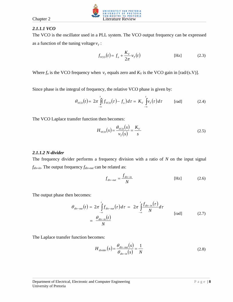
2.1.1.1 VCO
The VCO is the oscillator used in a PLL system. The VCO output frequency can be expressed
as a function of the tuning voltage Tv :
tvK
ftf TV
oVCO 2 [Hz] (2.3)
Where fo is the VCO frequency when Tv equals zero and KV is the VCO gain in [rad/(s.V)].
Since phase is the integral of frequency, the relative VCO phase is given by:
dvKdfftt
TV
t
oVCOVCO 2
[rad] (2.4)
The VCO Laplace transfer function then becomes:
s
K
sv
ssH V
T
VCOVCO
(2.5)
2.1.1.2 N-divider
The frequency divider performs a frequency division with a ratio of N on the input signal
fdiv-in. The output frequency fdiv-out can be related as:
N
ff indiv
outdiv
[Hz] (2.6)
The output phase then becomes:
N
t
dN
fdft
indiv
tindiv
t
outdivoutdiv
2 2 [rad] (2.7)
The Laplace transfer function becomes:
Ns
ssH
indiv
outdivdivider
1
(2.8)

Chapter 2 Literature Review
Department of Electrical, Electronic and Computer Engineering P a g e | 9 University of Pretoria
2.1.1.3 Phase detector
The phase detector compares the phases of two signals and produces a voltage or current
output according to the phase difference:
inPDPPoutPD KKV 21 [V] (2.9)
Where KP is the gain of the phase detector with units of [V/rad] or [A/rad].
The Laplace transfer function becomes:
P
inPD
outPDPD K
s
sVsH
(2.10)
2.1.1.4 Loop filter
The loop-filter removes the correction pulses coming from the phase detector. This filtered
signal then becomes the DC control signal for the VCO. The loop-filter also affects the loop
dynamics such as stability, settling time and phase noise peaking. The transfer function of the
loop filter, GLF(s) will be defined by the filter circuitry employed. The filter implementation
can be either passive or active. General loop-filter circuitry follows in section 2.1.6.
2.1.1.5 Transfer function of the combined linear model
From linear systems theory [13] and [14] it follows that the closed loop transfer function of a
PLL is:
sH
sG
sGsG
sG
s
ssH
OLref
outPLL
1
1
211
1
(2.11)
Where G1(s) is the forward path, G2(s) the feedback path and HOL(s) the combined open loop
transfer function. From Figure 3 the forward and feedback paths can be determined:
s
sGKKsG LFVP1 (2.12)
N
sG1
2 (2.13)
The combined open loop transfer function then becomes:

Chapter 2 Literature Review
Department of Electrical, Electronic and Computer Engineering P a g e | 10 University of Pretoria
sN
sGKKsGsGsH LFVP
OL 21 (2.14)
The PLL closed loop transfer function Equation (2.11) then becomes:
sH
sHN
s
ssH
OL
OL
ref
outPLL 1
(2.15)
2.1.1.6 PLL loop stability
With any linear feedback control system, stability issues will arise. With a PLL the order of
the linear system is determined by the order of the loop filter; it is normally one higher than
the order of the loop filter. The smallest PLL order is a 2nd order system [13] whose stability
can be described in terms of its damping factor and its natural frequency n. Normally, for a
selected natural frequency n, the damping factor is chosen as 2
1 , assuring loop
stability [14].
In reality many PLL systems are higher order systems, making the use of damping factors etc.
void. In these systems it is better to describe loop stability with parameters of phase margin m
and loop bandwidth p. The stability of any feedback control system can be described with
these two parameters, including 2nd order systems [14].
Phase margin and loop bandwidth can be described in terms of the open loop transfer function
HOL(s) of a feedback control system. Figure 4 graphically depicts the open loop transfer
function of a typical PLL system, with p and m indicated. This is also known as a Bode plot.
From [14] the following definitions:
The loop bandwidth p is defined as the cross-over frequency where the loop gain is equal to
one:

Chapter 2 Literature Review
Department of Electrical, Electronic and Computer Engineering P a g e | 11 University of Pretoria
1)( pOL jH (2.16)
The phase margin m is defined as the phase difference from -180° at the cross-over frequency
or loop bandwidth p:
opOLm jH 180)(arg [°] (2.17)
For stability it is required that the phase margin be a maximum at the loop bandwidth p [23]:
0 pd
d
(2.18)
This maximum value of m will however affect the noise peaking of the PLL [27]. More
typical values are in the order of 60° plus.
p
Gain (dB)
0°
-180°
0 dB
Phase (°)
HOL( )j
HOL( )j
m
p
Figure 4. PLL typical open loop transfer function

Chapter 2 Literature Review
Department of Electrical, Electronic and Computer Engineering P a g e | 12 University of Pretoria
2.1.1.7 In-band and out-band terminology
In PLL literature in-band and out-band responses are sometimes referred to. From Figure 4
the in-band response is defined where the loop gain 1)( jHOL or to the left of p. The
out-band response is defined where the loop gain is small 1)( jHOL or to the right of p.
These terminologies will become important when discussing phase noise in a PLL system in
section 2.1.2 and further on.
2.1.2 PLL linear model with additive noise sources
The scope of any synthesizer design always includes noise or phase noise performance. For
this reason it is necessary to investigate the effects of additive noise introduced at the different
subsystems of a PLL. Figure 5 depicts the modified linear model with added noise
sources [15].
Figure 5. PLL linear model with additive noise sources
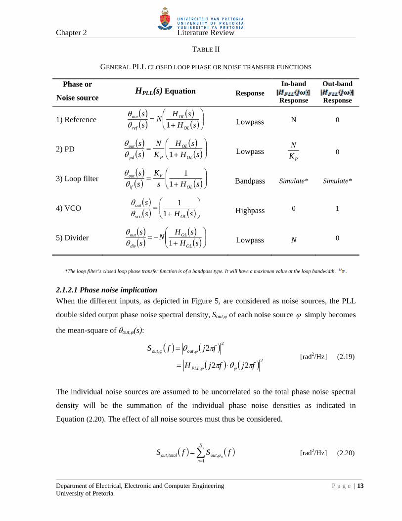
The noise sources are first treated as additional phase inputs so for each input a closed loop
transfer function HPLL(s) can be derived, similar to that of Equation (2.15). TABLE II then lists
the transfer functions for the different sources [15]. TABLE II also indicates the in-band and
out-band responses of these transfer functions.
Chapter 2 Literature Review
Department of Electrical, Electronic and Computer Engineering P a g e | 13 University of Pretoria
TABLE II
GENERAL PLL CLOSED LOOP PHASE OR NOISE TRANSFER FUNCTIONS
Phase or
Noise source HPLL(s) Equation Response
In-band
Response
Out-band
Response
1) Reference
sH
sHN
s
s
OL
OL
ref
out
1
Lowpass N 0
2) PD
sH
sH
K
N
s
s
OL
OL
Ppd
out
1
Lowpass PK
N 0
3) Loop filter
sHs
K
s
s
OL
V
lf
out
1
1
Bandpass Simulate* Simulate*
4) VCO
sHs
s
OLvco
out
1
1
Highpass 0 1
5) Divider
sH
sHN
s
s
OL
OL
div
out
1
Lowpass N 0
*The loop filter’s closed loop phase transfer function is of a bandpass type. It will have a maximum value at the loop bandwidth, .
2.1.2.1 Phase noise implication
When the different inputs, as depicted in Figure 5, are considered as noise sources, the PLL
double sided output phase noise spectral density, Sout,φ of each noise source simply becomes
the mean-square of out,(s):
2
,
2
,,
22
2
fjfjH
fjfS
PLL
outout
[rad2/Hz] (2.19)
The individual noise sources are assumed to be uncorrelated so the total phase noise spectral
density will be the summation of the individual phase noise densities as indicated in
Equation (2.20). The effect of all noise sources must thus be considered.
1
,,
N
nouttotalout fSfS
n [rad2/Hz] (2.20)
Chapter 2 Literature Review
Department of Electrical, Electronic and Computer Engineering P a g e | 14 University of Pretoria
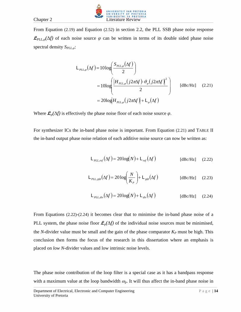
From Equation (2.19) and Equation (2.52) in section 2.2, the PLL SSB phase noise response
LPLL,φ(∆f) of each noise source φ can be written in terms of its double sided phase noise
spectral density SPLL,φ:
ffjH
fjfjH
fSf
PLL
PLL
PLLPLL
L
L
220log
2
2210log
2log10
,
2
,
,,
[dBc/Hz] (2.21)
Where Lφ(∆f) is effectively the phase noise floor of each noise source φ.
For synthesizer ICs the in-band phase noise is important. From Equation (2.21) and TABLE II
the in-band output phase noise relation of each additive noise source can now be written as:
fNf refrefPLL LL log20, [dBc/Hz] (2.22)
fK
Nf pfd
PpfdPLL
LL log20, [dBc/Hz] (2.23)
fNf divdivPLL LL log20, [dBc/Hz] (2.24)
From Equations (2.22)-(2.24) it becomes clear that to minimise the in-band phase noise of a
PLL system, the phase noise floor Lφ(∆f) of the individual noise sources must be minimised,
the N-divider value must be small and the gain of the phase comparator KP must be high. This
conclusion then forms the focus of the research in this dissertation where an emphasis is
placed on low N-divider values and low intrinsic noise levels.
The phase noise contribution of the loop filter is a special case as it has a bandpass response
with a maximum value at the loop bandwidth p. It will thus affect the in-band phase noise in

Chapter 2 Literature Review
Department of Electrical, Electronic and Computer Engineering P a g e | 15 University of Pretoria
the vicinity of the loop bandwidth and from there on the out-band phase noise. The effect is
best simulated; however at around p the following relation will be true:
fKf lfVflfPLLp
LL log202,
[dBc/Hz] (2.25)
Equation (2.25) dictates that the VCO gain constant KV and the phase noise floor Llf (∆f ) of the
loop filter be minimised to lessen the effect. Reducing KV is not always practical for a given
VCO but the noise floor Llf (∆f ) can be manipulated by choosing an active or passive loop
filter as will be discussed in section 2.1.6. With wide tuning range or high gain VCOs the
noise of the loop filter becomes important as it will adversely affect the out-band phase noise.
2.1.3 N-divider architectures
N-dividers in a PLL system divide the high frequency VCO output down to the required phase
comparison frequency. N-dividers consist mainly of flip-flops with feedback paths employing
combinational logic functions. These dividers can be grouped according to their mode of
operation, being asynchronous or synchronous.
2.1.3.1 Asynchronous dividers
In asynchronous dividers the output of the one block becomes the clock signal of the next
block. The advantage of an asynchronous architecture is that subsequent blocks operate at
lower frequencies than the first blocks. This then reduces power consumption. A very popular
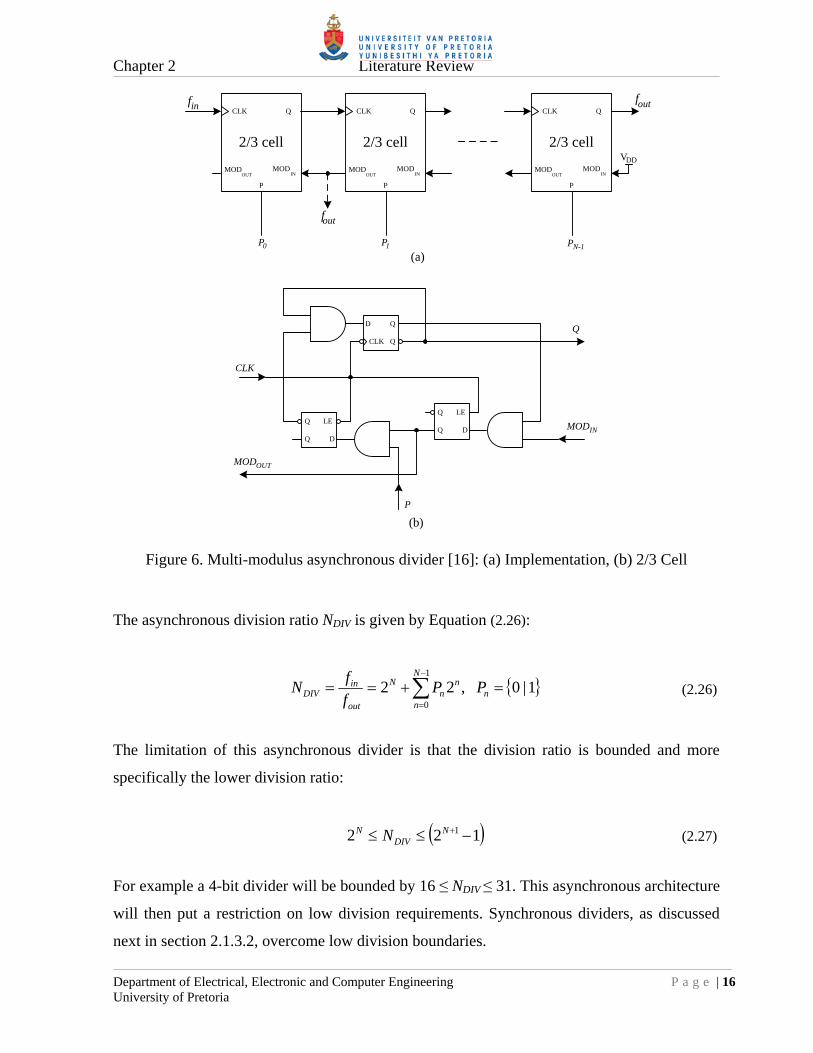
programmable asynchronous divider is from [16] and is depicted in Figure 6. This N-bit
divider consists of cascaded 2/3-cells and the programmable inputs are P0 ..PN-1.
Chapter 2 Literature Review
Department of Electrical, Electronic and Computer Engineering P a g e | 16 University of Pretoria
2/3 cell
CLK
P
Q
MODOUT
MODIN
2/3 cell
CLK
P
Q
MODOUT
MODIN
2/3 cell
CLK
P
Q
MODOUT
MODIN
DDV
P0 1 PN-1
D Q
QCLK
DQ
Q LEDQ
Q LE
CLK
Q
MODIN
MODOUT
P
(a)
(b)
fin fout
fout
P
Figure 6. Multi-modulus asynchronous divider [16]: (a) Implementation, (b) 2/3 Cell
The asynchronous division ratio NDIV is given by Equation (2.26):
1|0 ,221
0
n
N
n
nn
N
out
inDIV PP
f
fN (2.26)
The limitation of this asynchronous divider is that the division ratio is bounded and more
specifically the lower division ratio:
122 1 NDIV
N N (2.27)
For example a 4-bit divider will be bounded by 16 ≤ NDIV ≤ 31. This asynchronous architecture
will then put a restriction on low division requirements. Synchronous dividers, as discussed
next in section 2.1.3.2, overcome low division boundaries.

Chapter 2 Literature Review
Department of Electrical, Electronic and Computer Engineering P a g e | 17 University of Pretoria
2.1.3.2 Synchronous dividers
In synchronous dividers, all the building blocks share the same clock signal. In general
synchronous dividers are faster than asynchronous dividers due to the fact that there are no
clock propagation delays between subsequent blocks. Synchronous dividers are generally
implemented as counters. A conventional 4-bit down-counter is depicted in Figure 7:
Figure 7. TFF synchronous counter implementation
The counter consists of cascaded toggle-flip-flops (TFFs) and programmable inputs B0..B3.
Operation is such that when the count value reaches zero, the new B count value will be
loaded synchronously by the LOAD signal. As seen in Figure 7, a synchronous counter uses
TFFs. A TFF is a special kind of flip-flop where the output only changes state when the toggle
input T is asserted. Typical loadable TFF implementations, using D-flip-flops (DFFs), are
depicted in Figure 8.
D Q
QCLK
CLK
T
QD Q
QCLK
CLK
T
Q
(a) (b)
LOADP LOADP
MUX0
1SEL
MUX0
1SEL
MUX0
1SEL
Figure 8. Loadable TFF implementations: (a) XOR feedback, (b) MUX feedback

Chapter 2 Literature Review
Department of Electrical, Electronic and Computer Engineering P a g e | 18 University of Pretoria
In this dissertation however, a different approach was taken on the implementation of a
synchronous counter, using look up tables (LUTs), as will become evident in chapter 4
section 4.2.4.
The count range of an N-bit synchronous counter is given by Equation (2.28) and the
equivalent frequency divider NDIV range by Equation (2.29):
12 0 NCount (2.28)
N
DIVN 2 2 (2.29)
The lower divider limit of 2 is due to the fact that for a counter to produce an output clock or
output pulse, the minimum count value must be one. A zero count or a hypothetically divide
by one scenario will not produce a pulse but only a steady state output signal.
2.1.3.3 Pulse-swallow dividers
As seen from the previous sections, dividers consist mainly of flip-flops with combinational
logic in the feedback paths. The maximum divider operating frequency is then a function of
the individual propagation delays of the flip-flops and combinational logic. In a standard
0.35 µm CMOS implementation, such as the AMS C35 process, the typical propagation delay
for a DFF or a two-input NOR-gate is about 1 ns. This means for a cascaded NOR-DFF path
the delay is 2 ns, implying a maximum clock frequency of 500 MHz. For dividers required to
operate in the multi GHz range, these delays are too long. To overcome this problem either a
faster or more expensive process could be selected or prescalers could be used. The
pulse-swallow divider, employing a prescaler, is then an option [1]. Figure 9 depicts a typical
pulse-swallow divider.

Chapter 2 Literature Review
Department of Electrical, Electronic and Computer Engineering P a g e | 19 University of Pretoria
Dual modulus prescaler
fclkP / (P+1) B
LOAD
A
LOAD
MC
fdiv
B-counter
A-counter
0 = P 1 = P+1
Figure 9. Pulse-swallow divider
The pulse-swallow divider consists of a dual modulus prescaler P and two conventional
counters A and B. The A and B counters are sometimes referred to in literature as the swallow-
counter and program-counter respectively [1]. For the pulse-swallow divider to work in a
continuous mode the following condition must always be met: B ≥ A.
The operation is as follows:
1) The B-counter has just timed out and both A and B counters are loaded with new values.
2) The prescaler now divides by P + 1 until the A-counter times out.
3) For the remaining B - A cycles in the B-counter, the prescaler divides by .
4) Eventually the B-counter times out and the divider cycle begins again.
The total number of fclk counts in the divider’s output fdiv cycle is then:
APBPABPAN 1 (2.30)
The minimum and maximum divider values can also be presented in terms of the A and
B-counter ranges. Normally the A-counter has a range of 1,0 PA and the B-counter must
adhere to the B ≥ A condition. So the minimum and maximum divider values become as
indicated in Equations (2.31) and (2.32):
Chapter 2 Literature Review
Department of Electrical, Electronic and Computer Engineering P a g e | 20 University of Pretoria
min
min
minminmin
PB
PB
APBN
0 (2.31)
11
1
max
max
maxmaxmax
BP
PPB
APBN
(2.32)
For a 2/3-prescaler and a 4-bit B-counter, as in the implementation of this dissertation, the
minimum and maximum divider values are Nmin = 4 and Nmax = 33, respectively. By choosing a
low prescaler value, low divider values are still possible. Extension of the divider values can
be obtained by increasing the number of bits in the B-counter.
2.1.4 Fractional-N division
"Fractional-N" Synthesis technology was introduced by Hewlet Packard for the first time with
the HP3335A Synthesizer in 1977 [17]. A fractional-N synthesizer is essentially a single-loop
digital synthesizer where the N-divider has been modified to divide by an integer plus a
fraction. In this way extended frequency resolution is obtained without reducing the reference
frequency. The main advantage of this approach is that by keeping the N-divider values low,
the system’s phase noise is not sacrificed, for the sake of frequency resolution. Loop settling
times can also be reduced by using possible higher loop bandwidths, due to the higher
reference or phase comparison frequency.
2.1.4.1 Fractional-N implementation
Division by a fraction is not possible with conventional dividers. Fractional division is
however possible by averaging the value of a divider between N and N+1 over a period of
time. A digital accumulator performs the averaging and the total averaging time of both N and
N+1 divisions, in terms of accumulator clock cycles, is known as the modulus (MOD) of the
system. The number of cycles where the divider divides by N+1 is known as the numerator
(FRAC) of the fractional division. The average divider value over time then becomes
fractional as indicated in Equation (2.33).

Chapter 2 Literature Review
Department of Electrical, Electronic and Computer Engineering P a g e | 21 University of Pretoria
FractionNMOD
FRACN
TT
TN
TT
TNNTN
NN
N
NN
NNave
1
1
1
1
1
(2.33)
And the PLL frequency resolution becomes:
MOD
fFreq ref
res [Hz] (2.34)
Figure 10 depicts a fractional-N implementation; it is a standard PLL block diagram with a
digital accumulator added to manipulate the N-divider. The N and N+1 altering is controlled
by the accumulator’s ‘overflow’ bit and the FRAC and MOD signals are the programmable
inputs, defining the operation of the accumulator. The accumulator derives its clock input
from the output of the N-divider.
PFD Loop filter VCO
N-divider
0 = N 1 = N+1
N / (N+1)
Accum
ulator
+
OverflowFRAC
MOD
Modulus result
CLK
fref fout
Figure 10. Fractional-N PLL block diagram

Chapter 2 Literature Review
Department of Electrical, Electronic and Computer Engineering P a g e | 22 University of Pretoria
In many fractional-N implementations the modulus value is fixed in hardware, typically by a
power-of-two 2n value, to ease the digital implementation. In this dissertation however the
value is implemented to be programmable.
TABLE III shows an example of accumulator operation. The repetitive cycle equals the
modulus value and the number of overflows generated in a cycle equals the FRAC part.
TABLE III
FRACTIONAL-N ACCUMULATOR OPERATION
2.1.4.2 Fractional spurs
A fractional-N system is not without problems. For a 1st order fractional system, such as this
one, fractional spurs will occur at multiples of the fractional frequency resolution, as stated in
Equation (2.34). These spurs occur due to the huge spikes that the PFD causes at each N or
N+1 alteration. This is normal for the PFD. To counter these fractional spurs, several on-chip
compensation techniques exist, but mostly at the cost of phase noise [1]. Three known
techniques are [1]:
a) Delay compensation
b) DAC phase interpolation
c) modulation
Not to risk phase noise degradation, an off-chip fractional spur compensation method is used
in the loop-filter for this dissertation. Details will follow in chapter 5.
Cycle CLK count Accumulator result(MOD = 5, FRAC = 3)
Overflow
1st 0 3 (3 MOD 5 = 3) 0
1st 1 1 (6 MOD 5 = 1) 1
1st 2 4 (4 MOD 5 = 4) 0
1st 3 2 (7 MOD 5 = 2) 1
1st 4 0 (5 MOD 5 = 0) 1
2nd 5 3 (3 MOD 5 = 3) 0
2nd 6 1 (6 MOD 5 = 1) 1

Chapter 2 Literature Review
Department of Electrical, Electronic and Computer Engineering P a g e | 23 University of Pretoria
2.1.5 Phase detector
In a PLL, the PD produces an output voltage or current according to phase difference between
the reference signal and the output of the frequency divider. The most elementary form of a
phase detector is a multiplying PD such as an analogue mixer or a digital XOR gate as
depicted in Figure 11 [13].
Figure 11. Multiplying PD: (a) Analogue mixer, (b) Digital XOR gate
As the name suggests, a multiplying PD works by multiplying two signals. The product will
be a DC component and a high frequency component. The latter will be filtered out by the
loop filter and only the DC component will remain. The two big disadvantages of multiplying
PDs are that they are duty-cycle sensitive and cannot detect frequency differences between the
input signals. In a PLL some form of frequency acquisition technique will always have to be
used in conjunction with a multiplier PD and the input duty cycles must be kept at 50 %, for
optimal operation [13].
2.1.5.1 Digital tri-state PFD
With the invention of the digital tri-state PFD, many of the problems associated with
multiplier PDs, were overcome. A tri-state PFD can detect both frequency and phase
differences between two signals and is also duty-cycle insensitive. The first version of the
digital PFD was published in 1976 by [18]. The version, as it is widely known today, is
depicted in Figure 12.

Chapter 2 Literature Review
Department of Electrical, Electronic and Computer Engineering P a g e | 24 University of Pretoria
DFF
D Q
QCR
D Q
QCR
tdelay
DFF
UP
DN
LD
VDD
VDD
fref
fdiv
Figure 12. Tri-state PFD
The edge-triggered tri-state PFD consists of two resettable DFFs and logic to produce the reset
signal. A weak point of a tri-state PFD is its dead zone (undetectable phase difference range).
This occurs when the phases of the two signals are in close proximity of each other. To correct
this, a delay is introduced in the reset path as depicted in Figure 12. The phase difference
becomes the differential average of the two output signals UP and DN.
The functionality of the PFD is such that there are only three possible output states (tri-state).
When the rising edge of the reference input fref leads that of the divided VCO output fdiv , the
PFD outputs are: UP=1, DN=0 and when the reference lags, the PFD outputs are: UP=0,
DN=1. When both input phases are the same, the PLL is in lock and the PFD outputs are:
UP=0, DN=0.
When in lock, the outputs will practically be low with narrow high going pulses due to the
delay in the reset path. With a tri-state PFD it is also possible to extract a lock-detect (LD)
indicator. When in lock, the LD output is essentially high with narrow low going pulses and
when out of lock the output will be low. All the narrow pulses, high or low, will
approximately have pulse-widths of tdelay.

Chapter 2 Literature Review
Department of Electrical, Electronic and Computer Engineering P a g e | 25 University of Pretoria
The tri-state PFD has an idealistic linear phase detection range of ±2π radians as depicted in
Figure 13. The transfer function in Figure 13 is the differential average K of the two output
signals and the slope 2PK
is the gain of the PFD where KP has units of [V/rad] or [A/rad].
Figure 13. Ideal tri-state PFD transfer function
2.1.5.2 Non-ideal PFD
Due to the delay in the reset path of the PFD, which avoids the dead zone problem, the actual
linear phase comparison range shrinks as shown in [20] to be:
refdelayLIN ft 2 ,2 [rad] (2.35)
Figure 14 depicts this scenario.

Chapter 2 Literature Review
Department of Electrical, Electronic and Computer Engineering P a g e | 26 University of Pretoria
-2
0 2
Real
Ideal
-KP
KP
(rad)
Figure 14. Real tri-state PFD transfer function
This reduced phase comparison range will not affect the gain of the PFD in the linear region.
However the PLL lock-time will increase and the reset delay will also set an upper limit for
the reference clock frequency when ∆ = π [20]:
delay
maxref t
=f2
1 [Hz] (2.36)
Chapter 2 Literature Review
Department of Electrical, Electronic and Computer Engineering P a g e | 27 University of Pretoria
2.1.5.3 Charge pump PFD
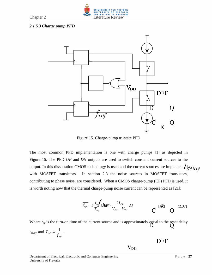
Figure 15. Charge-pump tri-state PFD
The most common PFD implementation is one with charge pumps [1] as depicted in
Figure 15. The PFD UP and DN outputs are used to switch constant current sources to the
output. In this dissertation CMOS technology is used and the current sources are implemented
with MOSFET transistors. In section 2.3 the noise sources in MOSFET transistors,
contributing to phase noise, are considered. When a CMOS charge-pump (CP) PFD is used, it
is worth noting now that the thermal charge-pump noise current can be represented as [21]:
fVV
IkT
T
t=i
THGS
CP
ref
onCP
242 2 [A2] (2.37)
Where ton is the turn-on time of the current source and is approximately equal to the reset delay
tdelay and ref
ref fT
1 .

Chapter 2 Literature Review
Department of Electrical, Electronic and Computer Engineering P a g e | 28 University of Pretoria
Equation (2.37) clearly shows the noise dependence on the reset delay. It follows from all the
above that the reset delay should be kept to a minimum in order to maximise clock frequency
and to minimise PLL lock-time and charge-pump phase noise. In reality the reset delay cannot
be made zero, as it is required to eliminate the dead-zone. It should be made long enough to
completely turn-on the switches in the CP PFD [22]. A minute pulse will not switch through
the current sources and the dead-zone will appear.
2.1.6 Loop filter architectures
Passive and active loop filter architectures will be considered in this section with a general 2nd
order transfer function as defined by Equation (2.38).
1
1
sT3sT2
sT1
si
svsG
CP
OLF (2.38)
T1, T2 and T3 are the loop filter time constants defined by the applicable PLL system. The
calculations of these time constants are discussed in section 2.1.6.3
2.1.6.1 Passive loop filter
A standard passive loop filter is depicted in Figure 16 with an optional additional filter as from
[24]. The additional filter helps with extra reference spur suppression. This architecture with
an additional fractional spur modification is then also used in this dissertation.
Ca
Ra
C1 R1
C2
Optional
vOiCP
Figure 16. Passive loop filter

Chapter 2 Literature Review
Department of Electrical, Electronic and Computer Engineering P a g e | 29 University of Pretoria
With a passive loop filter it is essential that the PFD CPs can do the voltage swing required to
tune the VCO. If not, an active loop filter must be considered or an approach where the
voltage swing of the CP can be extended, as is the case in the implementation of this
dissertation.
Adapted from [23] the equivalent time constants for the passive loop filter are defined by
Equations (2.39)-(2.41), as required by Equation (2.38):
C2R1T1 (2.39)
C2C1T2 (2.40)
C1T2
T1T3 (2.41)
The bandwidth of the optional reference spur filter is taken to be twenty times higher than the
loop bandwidth to not affect the resulting phase margin [24]. Calculation of the capacitor or
resistor values is then given by Equation (2.42):
pRaCa
20
1 (2.42)

Chapter 2 Literature Review
Department of Electrical, Electronic and Computer Engineering P a g e | 30 University of Pretoria
2.1.6.2 Active loop filter
Active loop filters are popular with wide tuning range VCOs as the upper limit of the output
voltage is only restricted by the supply voltage of the operational amplifier (OPAMP). A
typical active loop filter from [24] is depicted in Figure 17:
-
+
R1 C1
R2
C2
Ca
Ra
Optional
= VDDVREF /2
iCP
vO
Figure 17. Active loop filter
By analysing the transfer function of the OPAMP filter it can be shown that the equivalent
loop filter time constants are as indicated in Equations (2.43)-(2.45):
1CR1T1 (2.43)
C1T2 (2.44)
C2R2T3 (2.45)
The additional reference spur filter can also be calculated by Equation (2.42).
A major shortfall of active loop filters is noise. Unlike passive loop filters, the OPAMP in an
active loop filter is always “on” producing noise. The amount of noise will depend on the
OPAMP used. From Table II.3 the contribution of the OPAMP noise will have a bandpass
response, peaking at the loop bandwidth. Thus affecting the in-band phase noise in the vicinity
of the loop bandwidth and onwards the out-band phase noise. For this reason a passive loop
filter with a charge-pump voltage extension architecture was rather implemented in this
dissertation.

Chapter 2 Literature Review
Department of Electrical, Electronic and Computer Engineering P a g e | 31 University of Pretoria
2.1.6.3 Loop filter time constants calculation
The calculations of the loop filter time constants as required in Equation (2.38) are derived
from the stability guidelines presented in section 2.1.1.6 and with adaptations from [23].
Equations (2.16) and (2.18) are specifically used in the process to derive the time constants.
Equations (2.46)-(2.48) then defines the time constants in terms of the required phase margin
m , loop bandwidth p , VCO gain KV, phase-detector gain KP and the N-divider value:
p
mm
T3
180sec
180tan
(2.46)
T3N
KKT2
p
VP
3
(2.47)
T3
T1p
2
1
(2.48)

Chapter 2 Literature Review
Department of Electrical, Electronic and Computer Engineering P a g e | 32 University of Pretoria
2.2 PHASE NOISE
This section describes and explains the concept of phase noise and the negative implications of
phase noise in any communication or digital system. It will then become clear why it is
important for PLL systems to have low phase noise and hence in synthesizer ICs.
2.2.1 Phase noise basics
Phase noise occurs in all practical clock signals and oscillators due to time-varying phase
fluctuations which effectively spreads the carrier frequency. A sinusoidal clock or oscillator
with an output frequency of fc in Hz can be mathematically modelled as:
ttfAtv c 2cos [V] (2.49)
Where t then represents the random phase variation. When the phase variation t is
small, t << 1 rad, which will be the case for a stable carrier without FM modulation,
Equation (2.49) can be simplified using trigonometric identities to:
tftAtfAtv cc 2sin 2cos [V] (2.50)
This means that the spectrum of t is frequency-translated to cf or in other words the
carrier is spread by the noise profile.
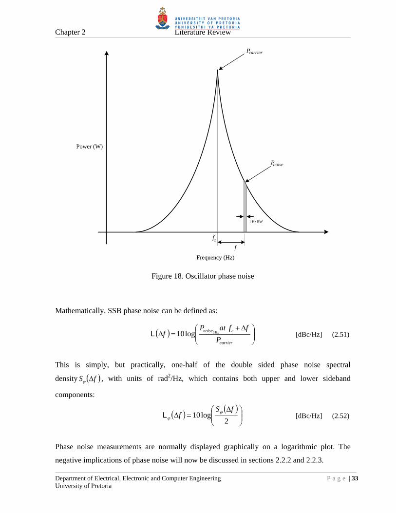
The measurement of phase noise is defined as such that it is measured as single sideband
(SSB) phase noise L(∆f) in dBc/Hz. This is defined as the ratio between the total carrier power
Pcarrier and the noise power Pnoise-1Hz, in a 1 Hz bandwidth, at a frequency offset ∆f from the
carrier as depicted in Figure 18.
Chapter 2 Literature Review
Department of Electrical, Electronic and Computer Engineering P a g e | 33 University of Pretoria
1 Hz BW
f
Frequency (Hz)
Pcarrier
Pnoise
Power (W)
fC
Figure 18. Oscillator phase noise
Mathematically, SSB phase noise can be defined as:
carrier
cnoise
P
ffatPf
log10 Hz 1 L [dBc/Hz] (2.51)
This is simply, but practically, one-half of the double sided phase noise spectral
density fS , with units of rad2/Hz, which contains both upper and lower sideband
components:
2log10
fSf
L [dBc/Hz] (2.52)
Phase noise measurements are normally displayed graphically on a logarithmic plot. The
negative implications of phase noise will now be discussed in sections 2.2.2 and 2.2.3.

Chapter 2 Literature Review
Department of Electrical, Electronic and Computer Engineering P a g e | 34 University of Pretoria
2.2.2 Reciprocal mixing
One of the unwanted side-effects of phase noise in a communication system, employing
mixers, is reciprocal mixing [25]. Reciprocal mixing is the effect due to the phase noise of the
local oscillator modulating the carrier of a strong signal. The carrier is then spread in
frequency which results in a power spectral density that is proportional to the local oscillator’s
SSB phase noise. When a receiver is tuned to a weak signal fRX near a strong carrier fc, the
resulting intermediate frequency (IF) spectrum may mask or block the weaker signal.
Figure 19 depicts this scenario.
BPF LNA BPF
LO
IF
Largesignal
weaksignal
Largesignal
Maskedweak signal
fIF
NoisyLO
fLO
fRXfc
Figure 19. The effect of LO phase noise on receiver sensitivity.
Reciprocal mixing will then ultimately reduce the receiver’s sensitivity in the presence of
large co-channel signals. In literature this is also known as part of the blocking capability of a
receiver [26].

Chapter 2 Literature Review
Department of Electrical, Electronic and Computer Engineering P a g e | 35 University of Pretoria
2.2.3 Jitter
Another unwanted side-effect from phase noise is time jitter. This becomes important for
clock signals in digital systems, especially for sampled systems such as wideband analogue to
digital converters (ADCs). It can be shown that the full-scale dynamic range of an ADC is
limited by the analogue input frequency and the jitter of the clock source [27]:
RMSanalogueFS tfSNR 2log20 [dB] (2.53)
Where fanalogue is the analogue input signal and ∆tRMS is the RMS time jitter on the clock. It is
thus important to minimise the time jitter as to maximise the possible full-scale signal-to-
noise-ratio (SNR) or dynamic range.
The sum of all phase noise in a band limited signal translates to the time domain as a residual
RMS phase jitter component and as an equivalent residual FM component. Time jitter can be
calculated from the residual phase jitter component. Shown next, is how to calculate these
residual components from an existing phase noise profile. The maximum value of these
residual components sometimes forms part of some system specification and hence the
additional need to calculate residual values. The equations used [1] originates from stochastic
noise processes theory.
2.2.3.1 Residual PM
Intuitively, residual phase jitter or residual phase modulation (PM) will also affect the possible
SNR obtainable in any phase modulation scheme, as an example quadrature phase shift keying
(QPSK), used in digital communications. It is not the scope of this dissertation to investigate
to what degree phase noise affects digital communications but to merely point out that the
effects exist.
The RMS residual phase jitter of a signal is related to the double sided phase noise spectral
density fS of the signal.

Chapter 2 Literature Review
Department of Electrical, Electronic and Computer Engineering P a g e | 36 University of Pretoria
The units of fS is rad2/Hz, so the RMS phase jitter becomes the square root of the integral
of fS over the band of interest f1-f2, as indicated in Equation (2.54):
2
1
f
f
RMS dffS [rad] (2.54)
From Equation (2.52) the relation to the logarithmic phase noise L(∆f) follows:
dff
f
f
RMS 2
1
10102L
[rad] (2.55)
With a given logarithmic phase noise plot of a signal and Equation (2.55) the residual RMS
phase jitter can then be calculated.
Calculating the RMS time jitter in seconds then just becomes a translation from radians to
seconds:
o
RMSRMS f
t 2
[s] (2.56)
Where fo is the frequency of the signal.
2.2.3.2 Residual FM
With analogue FM receivers or in the case of digital communications such as FSK systems,
the carrier or LO phase noise also have an effect on the quality of the demodulated signal.
With no modulation present in these systems, the demodulated output from the FM
discriminator will show a residual noise component. The dynamic range or SNR of the
demodulated signal is thus affected. This demodulated component is known as the residual
FM component of the phase noise. Residual FM is also important in radar systems but this is
beyond the scope of this dissertation.
Chapter 2 Literature Review
Department of Electrical, Electronic and Computer Engineering P a g e | 37 University of Pretoria
The residual RMS FM component is calculated by the stochastic noise process formula for
RMS, over the bandwidth of the demodulator f1-f2:
dffdffSfff
f
ff
f
RMS2102
2
1
2
1
102 L
[Hz] (2.57)
2.2.4 Conclusion
This then concludes the discussion on phase noise and why it is relevant in any
communication system and hence in a digital synthesizer IC.

Chapter 2 Literature Review
Department of Electrical, Electronic and Computer Engineering P a g e | 38 University of Pretoria
2.3 INTRINSIC NOISE
In electrical circuits, the three most common noise sources or types are [22]:
a) Thermal or Johnson noise
b) Flicker or 1/f noise
c) Shot noise
All of these noise sources can occur inside a synthesizer IC as they are generated internally by
transistors or resistors and are therefore referred to as intrinsic noise sources. These noise
sources will occur simultaneously in a circuit and can be distinguished by their spectral
densities as shown in Figure 20:
fcorner Frequency, log scale (Hz)
1/f noise
Thermal or Shot noise
Power (W)
Figure 20. Spectral density of different noise types
The frequency at which the thermal noise starts to dominate above the flicker noise is known
as the corner frequency fc or flicker cut off frequency.

Chapter 2 Literature Review
Department of Electrical, Electronic and Computer Engineering P a g e | 39 University of Pretoria
2.3.1 MOSFET small-signal noise model
This dissertation deals with a CMOS process so the three forms of intrinsic noise in
MOSFETs are discussed next. Intrinsic noise sources are small and can be modelled by
including their contribution in the MOSFET small-signal model as depicted in Figure 21:
Figure 21. MOSFET small-signal model with noise sources [22][28]
The MOSFET gate noise is modelled as a thermal noise voltage 2gv , for the gate resistance rg
and as a shot noise current 2gi , for the gate leakage current. The MOSFET channel noise
current 2di is modelled as a composite thermal and flicker noise component.
2.3.2 Thermal noise
Thermal noise occurs in any resistive circuit and is due to the random motion of electrons in a
conductor. The motion of these electrons is dependent on the absolute temperature and
therefore the name “thermal” noise. This motion of electrons then introduces voltage
fluctuations, or noise, across the conductor. Thermal noise has a white spectral density as
already depicted in Figure 20 and has a Gaussian amplitude distribution. The mean-square
(open-circuit) voltage and (short-circuit) current noise is modelled as [29]:
fkTR=vn 4 2 [V2] (2.58)
R
fkT=in
4 2 [A2] (2.59)

Chapter 2 Literature Review
Department of Electrical, Electronic and Computer Engineering P a g e | 40 University of Pretoria
Where k = 1.38 10-23 J/K is the Boltzmann constant, R is resistance of the conductor, ∆f is
the unit bandwidth and T is the temperature in Kelvin.
Referring to Figure 21, thermal noise in a MOSFET occurs in two places, in the gate and in
the drain-source channel. The gate noise voltage 2gv is due to the resistance of the gate rg and
is reduced by using multiple-finger designs as in section 4.2.1.6. The dominating thermal
noise component in a MOSFET is the channel noise current 2di [22]. Intuitively 2
di is expected
to be dependent on the saturation mode output resistance ro, as depicted in Figure 21 and
defined in Equation (2.60) [30]:
1
D
A
Do I
V
I=r
[] (2.60)
Where λ is the channel-length modulation parameter, VA the Early-voltage of the process used
and ID the drain current.
However research [31][32] suggests that the thermal noise current 2di is rather given by:
fgkT=i md 4 2 [A2] (2.61)
Where is a noise coefficient and gm the transconductance of the MOSFET.
From enhancement MOSFET theory, the drain current of a MOSFET in saturation mode, is
given by Equation (2.62) and can be approximated due to a normally small channel-length
modulation parameter λ:

Chapter 2 Literature Review
Department of Electrical, Electronic and Computer Engineering P a g e | 41 University of Pretoria
2
2
2
1
12
1
THGSox
DSTHGSoxD
VVL
WC
VVVL
WCI
[A] (2.62)
Where µ is the charge mobility, Cox is the gate capacitance per unit area, W/L is the transistor
aspect ratio, VGS the gate-source voltage, VTH the process threshold voltage and VDS the
drain-source voltage.
The transconductance gm is defined as the partial derivative of ID:
THGSox
constVGS
Dm
VVL
WC
V
Ig
DS
[S] (2.63)
The saturation transconductance of a MOSFET can also be shown to be equal to [22]:
THGS
Dm VV
I=g
2
[S] (2.64)
Hence the origins of Equation (2.37) in section 2.1.6.1 describing the thermal noise of a
charge-pump PFD.
To reduce thermal noise in a MOSFET, it follows from Equation (2.61) that the
transconductance gm must be minimised. This is achieved by maximising the gate voltage
swing VGS or reducing the drain current ID as suggested by Equation (2.64). This conclusion
will become important when designing current mode logic circuits.
2.3.3 Flicker noise
Flicker noise dominates the noise spectrum at low frequencies. The noise spectral density is
inversely proportional to frequency as depicted in Figure 20. For this reason flicker noise is
also called 1/f noise or “pink” noise. It is generally understood that flicker noise originates in

Chapter 2 Literature Review
Department of Electrical, Electronic and Computer Engineering P a g e | 42 University of Pretoria
any device due to surface charge effects [22]. Flicker noise occurs in a MOSFET due to
surface effects at the interface between the gate oxide and the silicon substrate [22]. Since the
silicon crystals of the substrate reach an end at this interface, many “dangling” bonds appear,
giving rise to extra energy states. As surface charge carriers move at the interface, some are
randomly trapped and later released by these energy states, introducing “flicker” noise in the
drain current. Unlike thermal noise, flicker noise power cannot be easily predicted and as such
are different from one CMOS technology to another. The general drain noise current spectral
density is given by Equation (2.65) [22]:
ff
I
LWC
K=i D
oxd
2 [A2] (2.65)
Where K is a process specific noise coefficient. The inverse dependence of (2.65) on area W
L suggests that to decrease 1/f noise, the device area must be maximised or the drain current
ID must be reduced. This becomes important when designing low noise current mirrors, such
as used in CML circuits.
As a final remark on 1/f noise, it is known that bipolar junction transistors (BJTs) are less
subjected to 1/f noise than MOSFETs [33]. Intuitively this can be explained due to the fact that
the majority of the collector-emitter current flows through the bulk of the device and not as
with MOSFETs close to the surface. It is also believed that PMOS devices may exhibit less
flicker noise than NMOS devices due to the fact that the holes are carried in a “buried”
channel, not close to the oxide-silicon interface [22].
2.3.4 Shot noise
Shot noise is caused by the fact that a DC flowing across a potential barrier, such as a P-N
junction, is not smooth, but is comprised of individual electrons arriving at random times. This

Chapter 2 Literature Review
Department of Electrical, Electronic and Computer Engineering P a g e | 43 University of Pretoria
random flow gives rise to broadband white noise that gets worse with increasing current. The
spectral density of shot noise is given by [29]:
fqI=i DCd 2 2 [A2] (2.66)
Where q = 1.6 10-19 C is the electron charge. MOSFETs operating in the saturation region
have very little shot noise due to the small gate leakage current and can be ignored for all
practical reasons. In the sub-threshold region, shot noise dominates (instead of thermal noise)
[34], but MOSFETs are rarely used in this region.
2.3.5 Noise to phase jitter translation
The effect of noise on a clock signal is discussed in this section as most subsystems inside a
digital PLL are clocked digital blocks. Any noise voltage on the clock input of a digital block
will introduce jitter and hence phase noise on its output. The noise-to-jitter translation will
occur at the switching threshold voltage VTH of the clock input. Figure 22 depicts a typical
clock waveform with a period of T seconds and a slew rate of λ V/s at the switching
voltage VTH.
Figure 22. Digital clock waveform
Chapter 2 Literature Review
Department of Electrical, Electronic and Computer Engineering P a g e | 44 University of Pretoria
When a RMS noise voltage nv is present on the clock waveform, it follows from Figure 22 that
the resulting RMS time jitter introduced at VTH is:
THVv
nn dt
dVvt
,
[s] (2.67)
The resulting RMS phase jitter n then becomes:
nnn
v
Tt
T
22 [rad] (2.68)
From Equation (2.68) it follows to minimise phase jitter; the slew rate of the clock waveform
must be made as high as possible and the noise voltage should be made as small as possible. In
practice these two requirements are conflicting. High slew rates generally implies high
bandwidth designs which in turn implies high current designs. High current designs, as was
seen earlier in this section, increase the levels of all noise types in transistors.

Chapter 2 Literature Review
Department of Electrical, Electronic and Computer Engineering P a g e | 45 University of Pretoria
2.4 PLL IC FIGURE OF MERIT (FOM)
A figure of merit (FOM) was first proposed by [1] to compare the in-band phase noise
plateaus of different digital synthesizer ICs employing digital tri-state PFDs. In literature it is
also known as the normalized phase noise floor L1Hz. It differs from device to device and gives
an idea of the amount of intrinsic noise jitter present in the dividers and PFD [35]. From a
synthesizer IC design perspective it then becomes important to minimise the FOM.
For illustration a typical logarithmic PLL phase noise plot with an in-band plateau is depicted
in Figure 23. With the FOM known it is then possible to predict the absolute value of this
plateau. This plateau is the same plateau that was illustrated in Figure 1. The FOM is only
applicable to the plateau and not to any sloped regions such as flicker noise.
SS
B p
hase
noi
se (
dBc/
Hz)
Figure 23. Typical PLL phase noise plot with in-band plateau

Chapter 2 Literature Review
Department of Electrical, Electronic and Computer Engineering P a g e | 46 University of Pretoria
The FOM is a normalized 1-Hz phase noise floor with respect to the phase comparison
frequency fR at which the PFD operates and is defined as [1]:
RfNfFOM log10log20 1Hz LL [dBc/Hz] (2.69)
TABLE IV compares the FOMs attained by other scholarly work and by this work:
TABLE IV
FOM COMPARISON
Reference Technology L1Hz (dBc/Hz) [3] 0.35 µm SiGe BiCMOS -213 [4] 0.5 µm CMOS -202 [5] 0.5 µm CMOS -211 [11] 0.18 µm CMOS -221 [12] 90 nm CMOS -222
This work 0.35 µm CMOS -225
What is evident is the 12 dB improvement over a previous 0.35 µm SiGe BiCMOS process.
2.4.1 Phase noise prediction from FOM
As mentioned, when the normalized phase noise floor of an IC is known, it can be used to
accurately predict the in-band phase noise performance for different divider ratios and phase
comparison frequencies, provided the loop bandwidth is large enough to negate the effect of
the VCO’s phase noise contribution. This is shown in Equation (2.70) by rearranging
Equation (2.69):
RfNf log10log20 1Hz LL [dBc/Hz] (2.70)
Equation (2.70) is very similar to Equation (2.22) as it once again shows the phase noise
dependence on the N-divider value and in addition now to the phase comparison frequency fR.
It basically states that the noise floor of a digital PFD will increase by a 10 log factor of the
comparison frequency. This is a major drawback of a digital PFD, but the effect of reducing

Chapter 2 Literature Review
Department of Electrical, Electronic and Computer Engineering P a g e | 47 University of Pretoria
the N-divider still outweighs the effect of an increased comparison frequency, as is shown
next.
For a fixed PLL output frequency fout, the N-divider value and the comparison frequency are
related as by Equation (2.1), so Equation (2.70) can be rewritten in terms of just the N-divider
or comparison frequency:
Nff out log10log10 1Hz LL [dBc/Hz] (2.71)
Rout fff log10log20 1Hz LL [dBc/Hz] (2.72)
To minimise the phase noise of a digital PLL, Equation (2.71) still indicates that the N-divider
must be as small as possible and in addition Equation (2.72) indicates that the phase
comparison frequency must be as high as possible. Both equations indicate that the FOM or
L1Hz must be minimised as well.
2.4.2 FOM underlying cause
The concept of the 1 Hz FOM was first introduced by [1] but analytical models for the FOM
limit have been investigated by several as in [2][3][35] and modelled as jitter being present at
PFD input. From [2] Equation (2.73) indicates the relation of the FOM to the PFD input RMS
timing jitter int :
220log 1 inHz t L [dBc/Hz] (2.73)
Equation (2.73) shows that the FOM or L1Hz has a 20 log relationship to the RMS timing jitter
present at the input of the PFD. To minimise the FOM it is thus essential to minimise this
timing jitter. This timing jitter is due to intrinsic noise processes inside the synthesizer IC as
presented in section 2.3.
Chapter 2 Literature Review
Department of Electrical, Electronic and Computer Engineering P a g e | 48 University of Pretoria
2.5 CURRENT MODE LOGIC
CMOS static logic is widely used in integrated circuits because of its scalability, high packing
density and wide noise margins, etc. However CMOS static logic has speed and dynamic
power dissipation limitations. The dynamic power dissipation of static CMOS is given by
[36].
fCVPD2 [W] (2.74)
Where C is the load capacitance, V the output voltage swing and f the switching frequency.
Another disadvantage of CMOS is the general absence of true complementary outputs,
creating the undesired need for additional inverters to implement this and in return increasing
propagation delays. Many of these limitations can be overcome by implementing CML
circuits.
CML or as it is sometimes referred to in literature as source-coupled logic (SCL), when using
MOSFETs, is generally recognized as one of the fastest switching logic topologies available.
CML has its differential origins from emitter-coupled logic (ECL) dating from the mid 1960s.
The power dissipation of a CML circuit is constant and independent of frequency, due to a
constant current source being used, and it has a lower output voltage swing than that of a static
CMOS circuit using the same supply voltage. The power dissipation will be higher than a
conventional CMOS circuit at low clock frequencies, but it will be less or equal at higher
frequencies. It is generally understood that the maximum clock frequency of a CML circuit
will be substantially higher than a conventional CMOS circuit due to its lower voltage swing
[37]. Another advantage of CML is its ability to suppress common mode noise such as
substrate noise, due to its differential architecture. A summary of basic operation will be
discussed next in section 2.5.1.

Chapter 2 Literature Review
Department of Electrical, Electronic and Computer Engineering P a g e | 49 University of Pretoria
2.5.1 CML basics
M1 M2
(a) (b)
0
VOUT =
-
vOUT
VIN, min
VDDVDD
VDDRDRD
RD
ITAIL
ITAIL
(V)
(V)
vOUT+vOUT-
vIN+ vIN-
vOUT-
vOUT+
vIN+ vIN-
Figure 24. CML Buffer: (a) Circuit, (b) Transfer function
The CML buffer shown in Figure 24 is a basic differential amplifier operating in its non-linear
(saturation) mode. For a certain minimum input differential voltage ∆VIN,min, one of the two
NMOS transistors M1 or M2, depending on the polarity of ∆VIN, will be in total saturation and
will act as a current steering switch for the current source ITAIL hence the name “current” mode
logic. As with all differential amplifiers the current source ITAIL aids with the buffer’s input
common mode extension [22] and ensures for input voltages greater than ∆VIN,min, the output
voltage ∆VOUT remains constant as ∆VOUT = ITAILRD. Since the circuit operates by completely
switching the current from the one to the other side, the logic high and logic low values
respectively are given by VDD and VDD – ITAILRD. From Figure 24, the only design parameters
of a CML buffer are the pull-up resistance RD, the size of the NMOS transistors and the tail
current ITAIL. From the square law for drain current of a NMOS transistor in saturation, the
relationship between the tail current and the minimum input voltage ∆VIN,min is given by
Equation (2.75) as from [38] [40]:
2min,2
1INoxTAIL V
L
WCI [A] (2.75)

Chapter 2 Literature Review
Department of Electrical, Electronic and Computer Engineering P a g e | 50 University of Pretoria
2.5.2 CML design guidelines
The two main parameters to be designed or estimated are the output voltage swing and the
minimum gate widths for the MOSFETs. The pull-up resistance RD will be calculated from the
required output voltage swing and the tail current ITAIL. The tail current will be determined by
bandwidth and output driving capabilities. The only design parameter left is the gate width W,
as the gate length L is normally kept at the smallest possible process length. A first order
design process for a CML buffer, as depicted in Figure 24, follows from [38] and is outlined
next.
2.5.2.1 Output voltage swing
For the CML buffer depicted in Figure 24, the drain voltage, referenced to ground, is given by
VD = VDD - ∆VOUT and hence the relative drain-source voltage VDS by:
SOUTDDDS VVVV [V] (2.76)
For the CML buffer to produce an output voltage ∆VOUT, it implies that the gate voltage must
be high or equal to VDD. The relative gate-source voltage VGS is then given by:
SDDGS VVV [V] (2.77)
For any MOSFET to operate in saturation mode it follows from MOSFET theory that the
following conditions must be true [22]:
THGSDSTHGS VVVVV and [V] (2.78)
Substituting Equations (2.76) and (2.77) in (2.78), the last part of (2.78) then simplifies to:
THOUT VV [V] (2.79)
Equation (2.79) places an upper limit for the output voltage if the buffer is to operate in pure
saturation mode. It is desirable for the buffer to operate in saturation mode as this will ensure
complete current switching from one side to the other.

Chapter 2 Literature Review
Department of Electrical, Electronic and Computer Engineering P a g e | 51 University of Pretoria
2.5.2.2 Output voltage swing in multilevel topologies
A design process for a single level CML buffer was outlined. In reality the majority of CML
circuits are multilevel; using stacked MOSFETs such as with multiplexers and D-latches etc.
Some examples of standard stacked CML building blocks will be presented in section 2.5.3.
Referring to the CML multiplexer in Figure 25, the individual drain to source voltages VDS of
the stacked MOSFETs will intuitively be less than that of a buffer [39]. For these stacked
MOSFETs to operate in saturation, it implies that ∆VOUT must be even smaller than the value
obtained from Equation (2.79), to satisfy the saturation VDS requirement in Equation (2.78). A
smaller ∆VOUT implies a smaller ∆VIN for the next stage and in turn implies much larger
MOSFETs. Larger MOSFETs will be needed for smaller gate voltages as will be seen from
Equation (2.80). This will seriously start hampering the bandwidth of the logic block due to the
increased gate capacitance.
From interpreting the work of others [39][40] it seems that bandwidth sacrifice can be
lessened by rather operating these stacked topologies in the upper triode MOSFET region.
This is done by increasing the CML output voltage swing ∆VOUT beyond the process threshold
voltage VTH. However a balance must be found as a too large voltage swing will increase the
propagation delay and complete current switching will not occur [40]. A 90 % current
switching scenario might still be adequate.
With stacked topologies it is then suggested that ∆VOUT initially be set to VTH and then
adjusted upwards if required. This will require parametric simulations for verification which is
not always desirable.
Chapter 2 Literature Review
Department of Electrical, Electronic and Computer Engineering P a g e | 52 University of Pretoria
2.5.2.3 Minimum MOSFET gate width
Generally with a CML design, the minimum input voltage swing ∆VIN,min, is taken to be the
nominal output voltage swing ∆VOUT or a bit less to allow for design tolerances. From
Equation (2.75) it then follows that the minimum gate width Wmin for a buffer, to allow
complete current switching, is calculated by:
2
,
2
minINox
TAILmin VC
LIW
[m] (2.80)
The inverse square relationship to the input voltage swing is clearly visible. A large Wmin will
however adversely affect the bandwidth of a MOSFET as the gate-capacitance is dependent on
the gate area W L:
oxg CLWC [F] (2.81)
2.5.2.4 Minimum MOSFET gate width in multilevel topologies
In a stacked MOSFET topology as in Figure 25, each level of differential pairs should be sized
separately, since the deeper a pair is located, the smaller its drain to source voltage and hence
the wider it will have to be to switch the tail current [39]. Therefore, the differential pairs must
be sized from the top down. Equation (2.80) is still a good estimate for the top differential pair
closest to the VDD rail. The differential pair closest to the tail current source can be much larger
than the top pair, as will be evident with D-latches in section 4.2.
2.5.2.5 CML flicker 1/f noise
By the current switching nature of a CML circuit, any CML circuit effectively becomes a
single-balanced current-commutating mixer. A current-commutating mixer implies any noise
present in the tail current will be up-converted to noise sidebands at the output frequency of a
CML circuit, visible then as phase noise. A detailed analysis on noise in CMOS current-

Chapter 2 Literature Review
Department of Electrical, Electronic and Computer Engineering P a g e | 53 University of Pretoria
commutating mixers can be found in [41]. The up-converted noise is an important
consideration for the flicker noise contribution of the current sources used. NMOS transistors
are normally used as the current sources in CML circuits. These transistors should then be
large, to reduce flicker noise, as from Equation (2.65) and [33].
2.5.3 CML standard building blocks
A good reference for standard CML building block topologies is [39]. For adders and XOR
implementations [42] can be referenced. Some of the more widely used blocks such as a
multiplexer, an AND/OR gate and a D-latch are shown briefly in Figures 25 to 27. Additional
CML building blocks will be designed in section 4.2.
2.5.3.1 CML multiplexer
M1 nAA B nB
nSEL SEL
M2 M3 M4
M5 M6
nQQ
SEL = ’0', Q = ASEL = ‘1’, Q = B
VDDVDD
RDRD
ITAIL
Figure 25. CML multiplexer

Chapter 2 Literature Review
Department of Electrical, Electronic and Computer Engineering P a g e | 54 University of Pretoria
From Figure 25 the SEL signal selects the output Q to be A or B by enabling transistors M5 or
M6.
2.5.3.2 CML AND/OR gate
M1 nAA
nBB
M2
M4
nQQ
M3
M5
Q = A · BnQ = nA + nB
VDD VDD
VDD
RDRD
ITAIL
Figure 26. CML AND/OR gate
The basic form for an AND/NAND gate is depicted in Figure 26. By applying De Morgan’s
theorem to invert the inputs and output, the AND gate can be reused to construct an OR/NOR
gate.

Chapter 2 Literature Review
Department of Electrical, Electronic and Computer Engineering P a g e | 55 University of Pretoria
2.5.3.3 CML D-latch
Figure 27. CML D-latch
The standard CML D-Latch is depicted in Figure 27 and consists of tracking and latching
sections. When LE=1, the transparent or tracking section is active. The tracking section
consists of transistors M1, M2 and M5. Any signal at the input D will then be replicated at the
output Q. When LE=0, the latching section, consisting of M3, M4 and M6, is active.
Transistors M3 and M4 form a regenerative cross coupled pair and will regenerate the logic
level that was present during the tracking phase. D-Latches are important as they form the
primary building blocks in DFFs as will be shown next in section 2.5.3.4.

Chapter 2 Literature Review
Department of Electrical, Electronic and Computer Engineering P a g e | 56 University of Pretoria
2.5.3.4 CML DFF
A CML DFF is constructed, like many other conventional DFFs, by combining D-latches in a
master-slave configuration:
Figure 28. Master-slave D-Flip-flop implementation
When CLK=0, the input signal D is sampled by the first D-latch which is in transparent mode.
The second D-latch at this stage is latching mode. When CLK=1 the modes are reversed and
the input signal, now at the output of the first D-latch, is transferred to the output Q on the
rising edge of the clock. The main advantage of a DFF is then that it is edge sensitive and not
level or duty cycle sensitive.

Chapter 2 Literature Review
Department of Electrical, Electronic and Computer Engineering P a g e | 57 University of Pretoria
2.6 CONCLUSION
A review was done over all the topics and subsystems required for a low noise CMOS
synthesizer IC implementation. This was done to aid research in pushing towards the
limitations of conventional CMOS processes. The information gathered here will then be used
in the design of the experimental CMOS synthesizer as outlined in chapter 4. The different
design considerations for a low noise digital synthesizer IC, derived from this chapter, are now
summarised in terms of PLL system requirements and on chip circuit requirements:
2.6.1 PLL system requirements
To minimise in-band phase noise coming from the PLL reference, divider and PFD circuits,
the following should be done:
a) N-divider values must be as small as possible
b) PFD comparison frequency must be as high as possible
c) PFD gain or the charge pump current ICP should be maximised, without degrading the
noise current
To meet requirement (a) an all CML fast low division N-divider topology is proposed in
chapter 4 and both a CML and CMOS-PFD are evaluated for requirement (b). Requirements
(a) and (b) will also inherently place restrictions on the tuning resolution of the proposed
synthesizer IC, but this is then overcome by using a fractional-N topology.
2.6.2 Circuit level requirements
The circuit level requirements have mostly to do with intrinsic noise levels and how to
minimise it so as to minimise timing jitter and hence resulting in a better FOM.
2.6.2.1 PFD reset pulse width
With a digital tri-state PFD it is essential to minimise the reset pulse width for the following
reasons:
a) The feed through of the charge pump noise to the loop-filter is minimised.
b) A high PFD operating frequency is achieved.
c) The phase comparison range of the PFD is maximised.
Chapter 2 Literature Review
Department of Electrical, Electronic and Computer Engineering P a g e | 58 University of Pretoria
2.6.2.2 CML voltage swing
The voltage swing of CML circuits must be optimised towards maximisation for two reasons:
a) Lower MOSFET thermal noise due to a larger overdrive voltage at the gate.
b) Higher bandwidth, less gate capacitance per MOSFET due to smaller MOSFETs that
can be switched by the larger voltage swings.
The voltage swing can however not be maximised indefinitely, as this will restrict the
switching MOSFETs to operate in saturation mode.
2.6.2.3 CML slew rate
The CML output slew rate must be maximised to minimise the intrinsic noise to jitter
translation in the output stage. This implies all output wave forms must be made as square or
as fast as possible and sinusoidal signals must be avoided or amplified to square waves.
2.6.2.4 CML tail current sources
In a CML circuit a 3-dimensional trade-off will exist between the tail-current ITAIL, the induced
noise current 2di and the bandwidth of the circuit. It follows from a bandwidth perspective that
the tail current must be maximised to reduce the RC effects from the output of one stage to the
input of another. From a noise perspective however it becomes important to reduce the tail
current. A balance must be struck between these two requirements, although bandwidth is
given precedence in the circuit implementation later.
Some freedom does exist in terms of the flicker noise contribution of the current sources.
From section 2.3.3 it follows that the area of a current source MOSFET can be increased to
reduce its flicker noise in a circuit. It is then envisaged that all current sources and current
mirrors used, should employ large devices.
This then concludes the literature review for this dissertation. Chapter 3 discusses next the
research methodology followed to experimentally validate the research and hence the
prototyped digital CMOS synthesizer IC.

CHAPTER 3: RESEARCH METHODOLOGY
This chapter describes the methodology followed to research the CMOS process limitations
inside the proposed high performance CMOS synthesizer IC.
3.1 RESEARCH METHODOLOGY OUTLINE
The research aim of this dissertation is to research CMOS process limitations as applicable to
synthesizer ICs. Research verification was done with the implementation of a high
performance CMOS synthesizer IC comparable with GaAs and HBT processes. The whole
research process is illustrated in Figure 29.
CML 2/3-prescaler
Literature and theory review
CML counters
PFDs + CMOS control logic
Experimental verification
Figure 29: Research flow diagram

Chapter 3 Research Methodology
Department of Electrical, Electronic and Computer Engineering P a g e | 60 University of Pretoria
The research process is started with a thorough literature review and theoretical study
regarding all aspects of low noise CMOS synthesizer IC design. These concepts or design
guidelines are then applied to three design stages as depicted in Figure 29. Finally the IC is
prototyped and experimentally verified in a laboratory. Experimental results are then
compared with theory. The three major design stages are described next.
3.1.1 CML prescaler design and prototype
In the construction of the high frequency programmable divider the first subsystem is a
2/3-prescaler. In the synthesizer IC the prescaler operates at the highest frequency. The
prescaler design is then fine tuned by simulations to yield the highest clock frequency
possible. To verify the validity of the high frequency simulations, the prescaler was laid out,
prototyped and tested. Measurement results provided valuable information for design
modifications and were then applied to the prescaler and subsequent design phases.
3.1.2 CML counter design
When the 2/3-prescaler proved operational, the next step was to design the all CML
pulse-swallow counter. The focus was first placed on the 4-bit program counter. Once again
the design was fine tuned through simulations to yield the highest clock frequency possible.
The CMOS pulse-swallow control logic was then designed and proven functional by
simulation. The combined operation of the prescaler, program and swallow counters were also
verified by simulation.
3.1.3 PFD and final design
A synthesizer IC is incomplete without a PFD. For research benchmarking both a CML and a
CMOS design were implemented, the phase noise effects were compared later. The CML
design was optimised for the smallest reset pulse width. Operation of the CMOS PFD was
verified through simulation. As part of this final design stage the programming interface was
also designed and simulated. Finally the IC was laid out and prototyped. Experimentally
measured results were then later compared with simulations.

Chapter 3 Research Methodology
Department of Electrical, Electronic and Computer Engineering P a g e | 61 University of Pretoria
3.2 CAD SOFTWARE USED
Integrated circuit (IC) design cannot be done without computer aided design (CAD) software.
Any CAD software used or a combination of should ideally encompass four basic functions:
a) Schematic capture
With schematic capture all electrical connections can be defined in a visual format. It is
used to physically represent the circuit as it would look when drawn by hand. Hierarchical
designs are possible due to the reuse of primitives and user defined building blocks.
b) Simulation
The initial validity of the proposed design will be based on simulation results. The most
basic simulator should be a Simulation Program with Integrated Circuit Emphasis (SPICE)
simulator. Foundry supplied models for active and passive components are used in the
simulations. These models normally consist of worst case process corner sets and a typical
mean set. Worst case models include worst case power and worst case speed conditions. It
is advisable that any IC design be simulated with these worst case scenarios and not just
the typical mean model. Additional RF simulators such as phase noise simulators will be
advantageous.
c) Physical layout
The physical layout is done with this package. The output rendering should be a graphic
data system II (GDSII) file which is accepted by most foundries as the definition or format
for IC fabrication. Built into the package should be a Design Rule Check (DRC) engine
that checks the layout against the foundry’s design rules.
d) Verification tools
A layout versus schematic (LVS) tool must be used. This verification tool extracts a net-
list from the layout and compares it with the net-list from the schematics.
Throughout the time of the particular research the Tanner EDA® package from Tanner
Tools® was available.

Chapter 3 Research Methodology
Department of Electrical, Electronic and Computer Engineering P a g e | 62 University of Pretoria
Tanner EDA® provides most of the basic functions as mentioned above at a reasonable price.
The individual Tanner components used are as follows:
Schematic capture: S-Edit
Simulation: T-Spice, W-Edit
Physical layout: L-Edit
Verification: HiPer Verify, L-Edit Standard DRC, L-Edit LVS
A limitation with the Tanner suite is that it has inadequate capabilities for simulating noise and
phase noise in general. A simulation package like SpectreRF® from the Virtuoso© Cadence
Design Systems suite would have been helpful in this dissertation.
3.3 IC PROTOTYPING
The IC prototyping was done using the Austriamicrosystems (AMS) 0.35 µm CMOS C35
process. The C35 process was chosen as it is representative of current state of the art CMOS
processes at a reasonable cost. An extract of the process features [50] are given in TABLE V.
Foundry data is protected by a non disclosure agreement (NDA) between the University of
Pretoria, AMS and the author. As a result of the NDA, foundry data [50] is not repeated in this
dissertation. It is also for this reason, TABLE V provides a range of values versus exact data.
It was decided to package the prototyped IC in a 56 pin surface mount Quad Flat No lead
(QFN) package. Figure 30 depicts a typical QFN package with width and length dimensions
added for a QFN-56 package.
Figure 30: QFN Package – top and bottom view
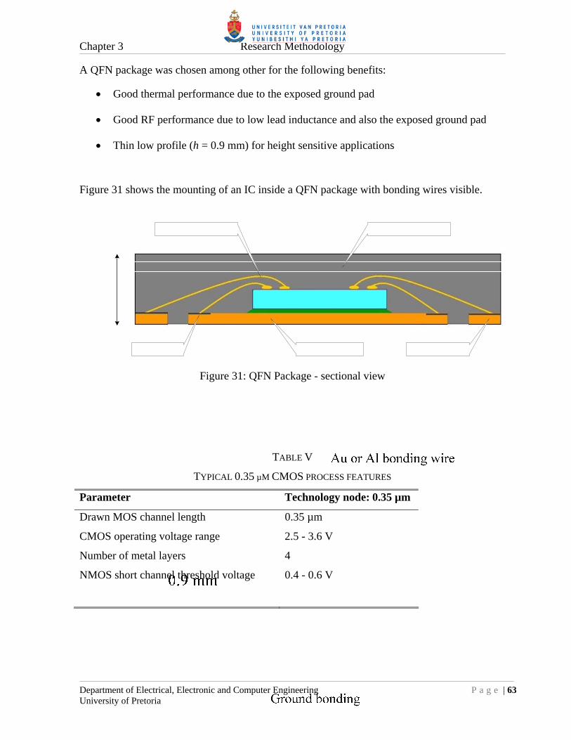
Chapter 3 Research Methodology
Department of Electrical, Electronic and Computer Engineering P a g e | 63 University of Pretoria
A QFN package was chosen among other for the following benefits:
Good thermal performance due to the exposed ground pad
Good RF performance due to low lead inductance and also the exposed ground pad
Thin low profile (h = 0.9 mm) for height sensitive applications
Figure 31 shows the mounting of an IC inside a QFN package with bonding wires visible.
Figure 31: QFN Package - sectional view
TABLE V
TYPICAL 0.35 µM CMOS PROCESS FEATURES
Parameter Technology node: 0.35 µm
Drawn MOS channel length 0.35 µm
CMOS operating voltage range 2.5 - 3.6 V
Number of metal layers 4
NMOS short channel threshold voltage 0.4 - 0.6 V

Chapter 3 Research Methodology
Department of Electrical, Electronic and Computer Engineering P a g e | 64 University of Pretoria
3.4 EXPERIMENTAL VERIFICATION
Two primary performance criteria must be verified with the prototyped CMOS synthesizer IC.
The one being the maximum operating frequency and the other the phase noise FOM. All
performance parameters will be tested by soldering the prototyped IC on an evaluation PCB,
programming the IC by some control interface and measuring the RF parameters with
laboratory test equipment. Details on the exact measurement procedures can be found in
chapter 5. A list of the proposed test equipment used will be presented in section 3.4.3.
3.4.1 Maximum operating frequency
The maximum operating frequency will be determined by sweeping the input frequency and
amplitude with a signal generator and then observing the output of the main divider with a
spectrum analyzer. This will be done for different programmed N-divider values; keeping the
output frequency in the order of 100 MHz. Figure 32 depicts the proposed setup.
Figure 32: Maximum operating frequency test setup
Figure 32 depicts a general system setup to measure maximum operating frequency. Aspects
like DC blocking capacitors and termination resistors have been omitted and will become
evident in chapter 5.

Chapter 3 Research Methodology
Department of Electrical, Electronic and Computer Engineering P a g e | 65 University of Pretoria
3.4.2 FOM
The FOM is assumed to be low and hence the resulting in-band phase noise, when the IC is
used stand alone in a PLL configuration. A standard high performance spectrum analyzer
might not be able to measure this low in-band phase noise accurately. To aid in phase noise
measurements, the IC will be tested in a 4 GHz PLL configuration with a wide loop filter.
An external low noise ÷4 prescaler will be added for an additional 12 dB of in-band phase
noise amplification. The total division ratio would now be the product of the external prescaler
and the programmed N-divider value of the prototyped IC. It should now be possible to
measure the in-band phase noise with a standard high performance spectrum analyzer.
Figure 33 indicates the proposed phase noise test setup:
Control
Figure 33: Phase noise test setup
In the PLL configuration it is proposed that a low noise 100 MHz reference crystal oscillator
be used. It is also envisaged that the VCO used could have a wide tuning range, implying a
high maximum tuning voltage. For this reason a high voltage CP circuit should be constructed
as indicated in Figure 33. Details will follow in chapter 5.

Chapter 3 Research Methodology
Department of Electrical, Electronic and Computer Engineering P a g e | 66 University of Pretoria
3.4.3 RF test equipment used
TABLE VI lists the RF test equipment used and their relevant specifications to this dissertation.
These are state of the art equipment and were available at Grintek Ewation (Pty) Ltd (GEW).
TABLE VI
RF TEST EQUIPMENT USED
Equipment Make Model Specifications
Signal generator Rohde & Schwarz (R&S) SMB 100A Freq: 9 kHz - 6 GHz
Spectrum analyzer R&S FSU8 Freq: 20 Hz - 8 GHz dBc/Hz 120fL @ ∆f = 10 kHz

CHAPTER 4: SYSTEM DESIGN
4.1 BACKGROUND
The goal of this dissertation is to research the possibility of implementing a low noise low
division (N < 40) synthesizer IC in a reasonably low cost 0.35 µm CMOS process with an
operating frequency in excess of 2 GHz. A fractional-N topology is also required. By doing
this the limitations of CMOS processes can be researched as applicable to high performance
synthesizer ICs. The AMS 0.35 μm CMOS C35 process was then selected for the
implementation.
As mentioned in chapter 1, one of the biggest design challenges is the high speed low division
programmable divider. An initial synchronous divider design was designed with standard 0.35
μm CMOS building blocks and simulated. It proved that the highest clock frequency was
about 500 MHz, far less than the 2 GHz required.
The CMOS divider topology was then ported to CML architecture and simulated. The
1.3 GHz result was better, as described in section 4.2.4.3, but still not what was required. It
was clear that a dual modulus prescaler of some sort was needed. However a prescaler would
impose a lower limit on the divide ratio, so the smallest dual modulus divide ratio, 2/3, was
chosen. Simulations with the CML 2/3-prescaler alone showed an upper frequency limit of
2.5 GHz and in the combined pulse-swallow divider architecture an upper limit of 2.3 GHz.
The lower boundary of the divide ratio was now limited to only four due to the minimum
divide ratios of the prescaler and program counter. All of this promised to be adequate.
To verify the high frequency simulation, the 2/3-prescaler was first prototyped and tested. The
measurement results concurred mostly with the simulation results. From this background a
synthesizer architecture was devised as shown in Figure 34.
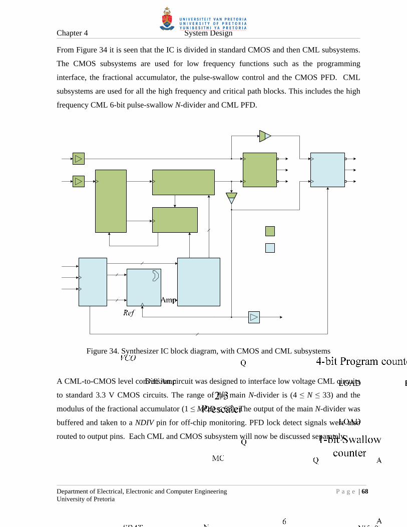
Chapter 4 System Design
Department of Electrical, Electronic and Computer Engineering P a g e | 68 University of Pretoria
From Figure 34 it is seen that the IC is divided in standard CMOS and then CML subsystems.
The CMOS subsystems are used for low frequency functions such as the programming
interface, the fractional accumulator, the pulse-swallow control and the CMOS PFD. CML
subsystems are used for all the high frequency and critical path blocks. This includes the high
frequency CML 6-bit pulse-swallow N-divider and CML PFD.
Figure 34. Synthesizer IC block diagram, with CMOS and CML subsystems
A CML-to-CMOS level conversion circuit was designed to interface low voltage CML circuits
to standard 3.3 V CMOS circuits. The range of the main N-divider is (4 ≤ N ≤ 33) and the
modulus of the fractional accumulator (1 ≤ MOD ≤ 63). The output of the main N-divider was
buffered and taken to a NDIV pin for off-chip monitoring. PFD lock detect signals were also
routed to output pins. Each CML and CMOS subsystem will now be discussed separately.

Chapter 4 System Design
Department of Electrical, Electronic and Computer Engineering P a g e | 69 University of Pretoria
4.2 CML SUBSYSTEMS
Basic analytical formulas and design guidelines exist for designing CML buffers as described
in section 2.5. With stacked CML topologies, such as a D-latch, these formulas become less
accurate [39]. These formulas still serve as an initial estimate for component sizes. Fine tuning
of the component sizes is done by using transistor-level simulations. These simulations are
first done with typical mean models for MOSFETs and polyresistors and then with models for
worst case process scenarios such as worst case power and worst case speed. The worst case
speed scenario is also an indication of what the IC will do in high temperature environments.
4.2.1 CML basics
The fundamental necessities in all the CML subsystems used are first discussed.
4.2.1.1 Output voltage swing
From section 2.5.2 and Equation (2.79) it follows that a first estimate for the CML output
voltage swing ∆VOUT is the nominal MOSFET process threshold voltage, VTH. From [50] it
follows that the average threshold voltage is VTH = 0.5 V with a tolerance of ± 20 %. Another
thing to consider is the pull-up polysilicon resistors used in all the CML circuits, affecting the
output voltage. These resistors also have a tolerance of ± 20 % [50]. The combined effect of
these device tolerances makes it difficult to design a CML circuit for all process corners. To
accommodate both device tolerances the CML output voltage swing ∆VOUT was scaled by
+40 % of the nominal threshold voltage VTH to become ∆VOUT = 0.7 V.
But section 2.5.2.2 also indicates that ∆VOUT will have to be higher than VTH to accommodate
stacked CML topologies to not sacrifice bandwidth. Through fine tuning simulations it was
found that ∆VOUT = 0.8 V proved to be optimum for all process corners, especially for the
D-latches and D-flip-flops.
4.2.1.2 Tail current strength
It was decided to accommodate different capacitive loads by categorizing the different CML
blocks in terms of their individual tail currents or then drive strengths. Standard tail currents
of 500 µA, 1 mA, 2 mA and 4 mA were selected for this purpose. This would then also imply
a fixed set of polysilicon pull-up resistors to achieve the output voltage swing.

Chapter 4 System Design
Department of Electrical, Electronic and Computer Engineering P a g e | 70 University of Pretoria
4.2.1.3 Minimum MOSFET gate widths
The minimum CML input voltage swing ∆VIN,min = 0.65 V was taken as the average between
the process threshold voltage VTH = 0.5 V and the chosen output voltage swing ∆VOUT = 0.8 V.
From Equation (2.80) and µCox = 170 µA/V2 [50], it follows that for a 2 mA tail current the
minimum gate width equals approximately W = 20 µm and for the other tail currents:
W(500 µA) = 5 µm, W(1 mA) = 10 µm and W(4 mA) = 40 µm. Many of the CML circuits will
however use wider devices for more gain.
4.2.1.4 NMOS current mirror
The current sources used in the CML blocks will be a NMOS transistor programmed by a
common bias or reference voltage VB. The bias voltage is the gate to source voltage of an
existing reference NMOS connected in a diode configuration, so that the current source, in
each CML block, mirrors the reference current. The reference current and bias voltage will be
set by an off-chip resistor RB as in Figure 35. It is assumed that the VDD rail will be voltage
regulated off-chip.
Figure 35. NMOS current mirrors
Reference voltage distribution is the easiest form of replicating currents around a chip but it is
very sensitive to ground voltage variations, leading to current modulation in the current

Chapter 4 System Design
Department of Electrical, Electronic and Computer Engineering P a g e | 71 University of Pretoria
sources [22][43]. A better way might be to distribute individual reference currents to each
current source and then locally mirroring the current. This will however introduce much more
complexity.
It was then decided to use the reference voltage option and by taking care that the ground
connection of each current source is at the same potential. This is done by having large metal
areas connecting the different ground sections and by having multiple ground pads on the
perimeter of the chip. In the final layout or floor plan of the IC, as depicted in Figure 76, this
is clearly visible. Off-chip these ground pads are then connected to the ground plane of the
evaluation printed circuit board (PCB). From a RF point of view and of a thermal conductivity
point of view this is also a good practise.
Current source transistor length L
To reduce the flicker noise in a CML block, the current source must be large as from section
2.5.2. For a current mirror configuration it is also important that the output impedance of the
current source be as high as possible. This will reduce current scaling errors when using
different sized mirrors. From Equation (2.60) the output impedance ro is proportionally
dependent on the Early voltage VA which in turn is dependent on the channel modulation
parameter λ. Equation (4.1) shows the dependence [30]:
'
1
L
VA [V] (4.1)
Where λ’ is the process specific channel modulation constant.
Equation (4.1) indicates to increase the Early voltage the MOSFET channel length L must be
increased. It was decided to reduce the channel modulation effect by three fold and hereby
arriving at L = 3 x 0.35 µm 1 µm. The desired effect was verified by simulating the current
mirror.

Chapter 4 System Design
Department of Electrical, Electronic and Computer Engineering P a g e | 72 University of Pretoria
Current source transistor width W
The minimum gate width W was determined by the current source requirement for the CML
level-shifted clock drivers, as will be seen in section 4.2.2. Here the current source had to have
a high compliance by working with quite a low drain voltage.
From Figure 35, the current reference transistor M1 is in a MOS-diode connection, which
implies that the drain-source voltage, or MOS diode voltage, is given by:
GSDSBMOSDIODE VVVV [V] (4.2)
M1 also operates in saturation mode so the drain current ID has the standard square voltage
relationship as in Equation (2.62). By rearranging Equation (2.62) the MOS diode voltage can
be calculated by Equation (4.3):
2
1
L
WC
IVV
ox
DTHMOSDIODE
[V] (4.3)
The MOS diode voltage is also the absolute minimum drain voltage at which the current
mirror can operate, to keep the transistor operating point in saturation. It is thus essential to
have a low minimum voltage here, to accommodate stacked CML topologies and CML level
shifting clock drivers. With a hypothetically large W/L ratio the absolute lower limit will be
the process threshold voltage VTH. TABLE VIII list MOS diode voltages for a 1 mA drain
current and some W/L ratios; all calculated by Equation (4.3) and µCox = 170 µA/V2 and
VTH = 0.5 V
TABLE VII
MOS DIODE VOLTAGES
W/L ID (mA) MOS diode voltage (V) 10 1 1.58 20 1 1.27 40 1 1.04 80 1 0.88
From TABLE VIII a transistor width of W = 80 μm was selected for a 1 mA current source.
This provided a reasonable low drain voltage operation (0.88 V) and a large transistor area for
low flicker noise considerations. Hence the transistor widths for the other standard tail current
sources were: W(500 µA) = 40 µm, W(2 mA) = 160 µm and W(4 mA) = 320 µm.

Chapter 4 System Design
Department of Electrical, Electronic and Computer Engineering P a g e | 73 University of Pretoria
External bias resistor RB
In the current mirror an accurate external bias resistor was chosen over an internal polysilicon
resistor due to the high polysilicon resistive tolerances ± 20 % [50]. These tolerances would
adversely affect the accuracy of the reference current. From Figure 35 the off-chip bias
resistor RB can be calculated, for a required reference current IREF and MOS diode voltage, by:
REF
MOSDIODEDDB I
VVR
[] (4.4)
For a 1 mA reference current and VMOSDIODE = 0.88 V the external bias resistor RB is calculated
from Equation (4.4) as RB = 2.4 k and rounded to the nearest Electronic Industries
Association (EIA) E12 series value: RB = 2.2 k. This ensured off the shelf availability.
4.2.1.5 Polysilicon resistors
Polysilicon resistors are used for all the pull-up resistors in the CML blocks. The polysilicon
has a maximum current density rating so the implemented resistor must be wide enough for
the required tail current. As mentioned before the resistivity specification also has a ± 20 %
tolerance [50]. In all the designs a 50-80 % margin has been left on the current density J
specification, to allow for increased current scenarios and for rounded calculated resistor
widths.
As an example, a 400 2 mA resistor is designed. From [50] it follows that
JPOLY2 = 0.3 mA/µm and RPOLY2 = 50 /µm2. For a rounded width a 66 % margin is chosen for
JPOLY2. The resistor width is calculated as:
μm 10 66.0100.3
102
margin 3-
3
2
POLYJ
IW
and the length :
μm 8050
40010
2
POLYR
RWL
To compact the layout, the resistor is laid out in a serpentine form as shown in Figure 36.

Chapter 4 System Design
Department of Electrical, Electronic and Computer Engineering P a g e | 74 University of Pretoria
Figure 36. 400 polyresistor layout
4.2.1.6 Fingered MOSFET and guard rings
With large MOSFETs, a technique exists to reduce the resistance of poly gates and to reduce
the individual capacitances of the drain and source terminals. This is done by breaking up the
gate in smaller shorter sections and then connecting them as fingers. This will then improve
the high frequency performance of the MOSFET. A similar layout as suggested by [44] is
shown in Figure 37. Here a 40 µm wide NMOS FET was broken up in 8 x 5 µm fingers.
25 µm
20 µm
Figure 37. Fingered 40 µm NMOS FET layout

Chapter 4 System Design
Department of Electrical, Electronic and Computer Engineering P a g e | 75 University of Pretoria
Also visible from Figure 37 are guard rings. These are metal rings connected with vias to P+
or N+ diffusions. They are necessary to shield the MOSFET from substrate noise or minority
carriers, all possibly injected by other devices into the substrate. Minority carriers can cause
the transistor to enter a latch-up state. To be safe two guard rings are used. The outer ring is a
N+ diffusion connected to VDD and the inner ring a P+ diffusion connected to ground. The
inner ring also serves as the bulk or substrate connection for the MOSFET.
4.2.1.7 NMOS decoupling capacitors
It is necessary to decouple the individual VDD power supply lines of each block from one
another, for reducing noise and interference. This is also important for the reference voltage of
the current sources. The decoupling is then done by NMOS capacitors. The reason for using
NMOS capacitors is that for any CMOS process used, the highest density capacitor can be
constructed by connecting the drain and source terminals of a NMOSFET together as the
negative electrode and then using the gate connection as the positive electrode. Figure 38
shows an example of a 1 pF NMOS capacitor:
Figure 38. 1 pF NMOS capacitor
The gate oxide diffusion capacitance for the AMS C35 process is Cox = 4.54 fF/µm2 [50]. For a
1 pF capacitance it is then required that the gate area should approximately be
220 µm2 15 µm x 15 µm. Figure 39 shows the symbol used in this dissertation for a NMOS
capacitor.
Figure 39. NMOS capacitor symbol

Chapter 4 System Design
Department of Electrical, Electronic and Computer Engineering P a g e | 76 University of Pretoria
4.2.2 CML CLK driver
It was seen from the work of [45][46][47] that the bandwidth or speed of a CML DFF could be
increased if the common mode voltage VCM of the clock signal was optimised. This implied
level shifting the clock signal downwards. Practically this resulted in smaller differential clock
transistors inside a CML D-latch. The speed improvement was thus partly due to less gate
capacitance. It was also seen that the output slew rate increased. The level shifting was done as
in Figure 40 by adding a common mode load resistor to a CML buffer.
Figure 40. CML level shifting DFF CLK driver
From simulations it proved that an additional 360 – 400 mV clock offset does improve the
speed of existing CML DFFs. A 180 poly resistor was used for the common mode load. All
CML DFF circuits were then equipped with this level shifting clock driver. As mentioned
earlier, this approach does put more strain on the low drain voltage compliance of the tail
current source.

Chapter 4 System Design
Department of Electrical, Electronic and Computer Engineering P a g e | 77 University of Pretoria
4.2.3 CML 2/3-prescaler
As stated earlier a 2/3-prescaler was required for the front-end of the main divider. This
prescaler should then be able to operate with an input frequency in the excess of 2 GHz.
4.2.3.1 Logic design
Any prescaler can be designed by first creating a count state table and then converting it to a
truth table by adding modulus control signal(s) and inserting dummy states to simplify the
combinational logic. The idea is to use minimal combinational logic to reduce propagation
delays. TABLE VIII then shows the count table for the 2/3-prescaler as required in this design.
The greyed entries are when the counter resets.
TABLE VIII
2/3-PRESCALER COUNT TABLE
÷3 ÷2
CLK Count Q1 Q0 Q1 Q0
0 0 0 0 0
1 0 1 0 1
2 1 0 0 0
3 0 0 0 1
From the count table, the next state truth table can be constructed as in TABLE IX for the
2/3-prescaler. The greyed entries indicate the chosen dummy or don’t care states, which will
never occur. These dummy states were chosen to simplify the resulting combinational logic.
The modulus control signal of MC=0 were chosen for the ÷2 operation and MC=1 for the ÷3
operation.
TABLE IX
2/3-PRESCALER TRUTH TABLE
÷3 ÷2
Present Next Present Next
MC Q1 Q0 Q1 Q0 MC Q1 Q0 Q1 Q0
1 0 0 0 1 0 0 0 0 1
1 0 1 1 0 0 0 1 0 0
1 1 0 0 0 0 1 0 0 0
1 1 1 1 0 0 1 1 0 0
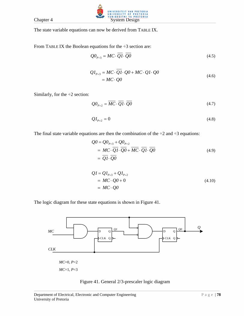
Chapter 4 System Design
Department of Electrical, Electronic and Computer Engineering P a g e | 78 University of Pretoria
The state variable equations can now be derived from TABLE IX.
From TABLE IX the Boolean equations for the ÷3 section are:
0Q1QMC0Q P 3 (4.5)
0QMC
0Q1QMC0Q1QMC1Q P
3 (4.6)
Similarly, for the ÷2 section:
0Q1QMC0Q P 2 (4.7)
02 P1Q (4.8)
The final state variable equations are then the combination of the ÷2 and ÷3 equations:
0Q1Q
0Q1QMC0Q1QMC
0Q0Q0Q PP
23
(4.9)
0QMC
0QMC
1Q1Q1Q PP
0 23
(4.10)
The logic diagram for these state equations is shown in Figure 41.
D Q
QCLK
D Q
QCLK
MC
CLK
QQ0Q1
MC=0, P=2
MC=1, P=3
Figure 41. General 2/3-prescaler logic diagram

Chapter 4 System Design
Department of Electrical, Electronic and Computer Engineering P a g e | 79 University of Pretoria
4.2.3.2 CML AND D-latch
From Figure 41 it is clear that AND gates are required before the DFFs, to implement the
2/3-prescaler. By example of [46], this is solved by merging an AND-gate with the master
D-latch in a master-slave DFF implementation. The primary goal is to reduce propagation
delays. Figure 42 depicts the merged AND-D-latch CML implementation.
nDADA 40/0.35
nQ
LE = ’1', Mode = TransparentLE = ‘0’, Mode = Latched
VDDVDD
40/0.3560/0.35
VDD
VDD
LE nLE
20/0.35 20/0.3520/0.35
60/0.35 60/0.35
160/1VB
nDBDB
455 445
Q
NMOS 1 pF15/15
= 2 mAITAIL
Figure 42. CML AND-D-latch schematic
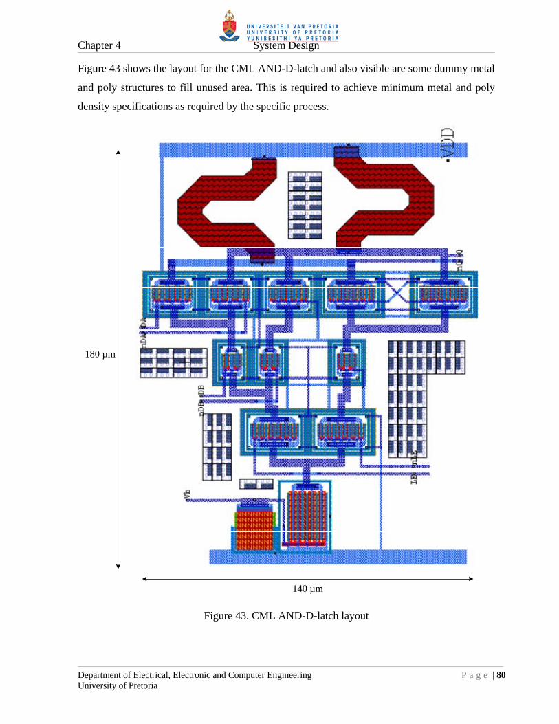
Chapter 4 System Design
Department of Electrical, Electronic and Computer Engineering P a g e | 80 University of Pretoria
Figure 43 shows the layout for the CML AND-D-latch and also visible are some dummy metal
and poly structures to fill unused area. This is required to achieve minimum metal and poly
density specifications as required by the specific process.
140 µm
180 µm
Figure 43. CML AND-D-latch layout

Chapter 4 System Design
Department of Electrical, Electronic and Computer Engineering P a g e | 81 University of Pretoria
4.2.3.3 Prescaler start-up meta-stability
In the 2/3-prescaler, signals are fed from the two DFF outputs to the inputs, via the AND
gates. During start-up the differential DFF outputs are at equilibrium, thus the differential
output voltage is zero. This meta-stability state will not continue indefinitely but will correct
itself after a while due to the gain present in the DFFs. This can be speeded up by purposely
offsetting the pull-up resistor values from one another in the master D-Latch to create an
initial voltage difference during start-up. In Figure 42 the nominal pull-up resistor value was
450 , so a 1 % or 5 offset was chosen and the resulting values were 445 and 455 .
This resulted in the 2/3-prescaler being operational within five clock cycles, which assisted for
simulation process.
4.2.3.4 Prescaler implementation
For the CML 2/3-prescaler to be fully functional it was necessary to include the previously
mentioned level shifters on the DFF clocks and an output buffer to provide enough drive
strength for the next stage, as depicted in Figure 44. In chapter 5 simulations were done for the
whole 6-bit pulse-swallow divider including the 2/3-prescaler, over all process corners. It was
then seen in one of the worst case process scenarios that the modulus control MC input signal
was captured too late. This resulted in a lower maximum frequency. To remedy this, an
additional D-latch synchronizing circuit was added to the MC signal as is visible in Figure 44.
B
IN
A
VB
Figure 44. CML 2/3-prescaler implementation

Chapter 4 System Design
Department of Electrical, Electronic and Computer Engineering P a g e | 82 University of Pretoria
The final layout of the CML 2/3-prescaler is shown in Figure 45 with some sub circuits such
as the VCO input amplifier and output buffer outlined.
820 µm
670 µm
10 pF NMOS decoupling capacitor
2/3-prescaler core
Output buffer
VCO amplifier & level shifting CLK
buffer
Figure 45. CML 2/3-prescaler layout
The VCO amplifier is similar to the reference clock amplifier as will be discussed in section
4.2.5. Visible also are 10 pF NMOS capacitors used for power supply decoupling between the
+3.3 V rail and ground.

Chapter 4 System Design
Department of Electrical, Electronic and Computer Engineering P a g e | 83 University of Pretoria
4.2.3.5 Prescaler simulation
The CML 2/3-prescaler was proven operational by worst case process simulations with clock
frequencies of 50 MHz - 2.5 GHz and MC = 1 or a ÷3 scenario. These included the effects of
the level shifting clock drivers and general output buffers. Figure 46 shows the simulation
setup and Figure 47 the resulting output waveform for a 2.5 GHz input frequency.
Figure 46. CML 2/3-prescaler simulation test protocol
Figure 47. CML 2/3-prescaler simulation
The 1.2 ns period of the output waveform is clearly visible. The 2/3-prescaler was also
prototyped on its own and results follow in chapter 5.

Chapter 4 System Design
Department of Electrical, Electronic and Computer Engineering P a g e | 84 University of Pretoria
4.2.4 CML 4-bit counter
The 4-bit CML counter is the heart of the programmable low division frequency divider. The
requirements are that the counter must be able to operate in excess of 1 GHz and be able to
count down from a maximum of 15 to a minimum of 0. A very important requirement is that
the counter should only load new counter values at the end of every count cycle. The counter
should be prohibited to load new values during a count cycle. This is important for the
fractional-N implementation as the digital accumulator, controlling the effective N-divider
value, may take a while to settle and initially corrupt the next required count value. For
integer-N architectures, this requirement is not necessary. The counter is then implemented as
a synchronous down counter.
4.2.4.1 LUT synchronous counter
It was decided, due to the many cascaded or chained AND and XOR gates in the conventional
synchronous TFF counter implementation as in Figure 7, section 2.1.3.2, a faster topology
could be designed by using look up tables (LUTs), for the state variables. Figure 48 depicts the
logic diagram of the LUT based synchronous counter, implemented in this dissertation. The
LOAD signal is also synchronized before using it as the divider output.
D Q
QCLK
D3LUT
Q3 Q2 Q1 Q0
D3 D Q
QCLK
D2LUT
Q3 Q2 Q1 Q0
D2 D Q
QCLK
D1LUT
Q3 Q2 Q1 Q0
D1 D Q
QCLK
D0LUT
Q3 Q2 Q1 Q0
D0
Q3 Q2 Q1 Q0
D Q
QCLK
LOAD
Q
B0B1B2B3
CLK
LOAD = Q3 Q2 Q1 Q0.. .
MUX
0
1 SEL
MUX
0
1 SEL
MUX
0
1 SEL
MUX
0
1 SEL
DFF DFF DFF DFF DFF
Figure 48. Synchronous LUT 4-bit counter
The LUT for each state variable Q3-Q0 was done by extracting the individual next state
columns in the truth table shown in TABLE X. The LUTs were then implemented as four CML
16-1 multiplexers.

Chapter 4 System Design
Department of Electrical, Electronic and Computer Engineering P a g e | 85 University of Pretoria
TABLE X
4-BIT COUNTER TRUTH TABLE
Present state Next state Count Q3 Q2 Q1 Q0 Q3 Q2 Q1 Q0 LOAD
15 1 1 1 1 1 1 1 0 0 14 1 1 1 0 1 1 0 1 0 13 1 1 0 1 1 1 0 0 0 12 1 1 0 0 1 0 1 1 0 11 1 0 1 1 1 0 1 0 0 10 1 0 1 0 1 0 0 1 0 9 1 0 0 1 1 0 0 0 0 8 1 0 0 0 0 1 1 1 0 7 0 1 1 1 0 1 1 0 0 6 0 1 1 0 0 1 0 1 0 5 0 1 0 1 0 1 0 0 0 4 0 1 0 0 0 0 1 1 0 3 0 0 1 1 0 0 1 0 0 2 0 0 1 0 0 0 0 1 0 1 0 0 0 1 0 0 0 0 0 0 0 0 0 0 0 0 0 0 1
4.2.4.2 CML 16-1 multiplexer
A 16-1 CML multiplexer was required for the LUT based synchronous counter. Figure 49
depicts the arrangement of four 4-1 multiplexers to create the 16-1 multiplexer and an instance
of how a 4-1multiplexer was created using three 2-1 multiplexers.
SE
L0
SE
L1
SE
L0
SE
L1
SE
L0
SE
L1
SE
L0
SE
L1
SE
L0
SE
L1
Figure 49. 16-1 multiplexer

Chapter 4 System Design
Department of Electrical, Electronic and Computer Engineering P a g e | 86 University of Pretoria
Figure 50 shows the layout for a CML 4-1 multiplexer, using three CML 2-1 multiplexers with
a circuit implementation as indicated previously in Figure 25.
240 µm
150 µm
Figure 50. CML 4-1 multiplexer layout
All the switching transistors are 20 µm wide and each multiplexer has a tail current of 1 mA.
The differential pull-up resistors are 780 and 820 respectively to resolve once again start-
up meta-stability problems when the multiplexer is used in conjunction with a DFF, as is the
case with the LUT counter implementation.
4.2.4.3 CML 4-bit counter simulation
The complete CML LUT 4-bit counter, including level shifting clock buffers, was proven
operational by worst case simulation with a maximum clock frequency of 1.2 GHz. Shown in
Figure 51 the simulation setup and in Figure 52 the simulation results for a count scenario of
B=4 or in other words a frequency divide by 5 scenario. The 4.17 ns period of the output
waveform is clearly visible.

Chapter 4 System Design
Department of Electrical, Electronic and Computer Engineering P a g e | 87 University of Pretoria
CML 4-BIT COUNTER
B0
VB
CLK
Q
VB
80/1
VDD
= 1 mA
R = 2.4 kB
IREF
VDD
LOAD
Q
B=4
+-
0.6 Vpp
1.2 GHz
= 3 VVCM
B1B2B3
LOAD
Figure 51. Synchronous CML LUT 4-bit-counter simulation test protocol
The CML clock input signal is modelled as 0.6 Vpp square wave with a DC-offset of 3 V.
Figure 52. Synchronous CML LUT 4-bit-counter simulation

Chapter 4 System Design
Department of Electrical, Electronic and Computer Engineering P a g e | 88 University of Pretoria
4.2.5 CML reference clock amplifier
For minimum noise to jitter translation, it is required that all signals be square waves. This is
predominantly a problem with the low frequency reference clock. A dual high gain amplifier
stage, as shown in Figure 53, was designed to convert the reference sinusoidal signal to square
waves. It uses four wide 80 µm MOSFETs. In the CML 2/3-prescaler a similar clock amplifier
circuit was used as the VCO input amplifier. The major difference was the output buffer being
replaced by two level shifting clock drivers.
160/1VB
80/0.3580/0.35 In-In+
480 480
3300
VDD
VDD
500
3300
80/0.3580/0.35
VDD VDD VDD
400 400
NMOS 1 pF15/15
VB
Out+Out-
160/1
= 2 mA= 2 mAITAIL
ITAIL
Figure 53. CML reference clock amplifier
From Figure 53, the input signals In+ and In- are mid VDD biased by two on-chip 3300
polyresistors. This will ensure a wide input dynamic range operation. The In+ signal is
connected by a 500 resistor to the In- signal. This provided both a common DC voltage
between the In+ and In- terminals and a way to fix the differential input impedance to 500 .
It also provided an easy way to verify the on-chip resistor tolerances of a prototyped IC by
measuring the resistance of the In+ and In- terminals. A 500 input impedance was deemed

Chapter 4 System Design
Department of Electrical, Electronic and Computer Engineering P a g e | 89 University of Pretoria
adequate as this was a moderate impedance which could easily be off-chip matched to either
200 or 50 systems.
To accommodate large input signals, up to +10 dBm in a 50 system, the 500 input
polyresistor had to be large or wide. A resistor 2 mA RMS current rating was derived from
the +10 dBm specification, implying a minimum polyresistor width W = 10 µm.
4.2.5.1 CML reference clock amplifier simulation
The circuit was simulated with a 150 MHz signal and found to be operational. Figure 54
depicts the simulation setup and Figure 55 the sinusoidal to square wave waveform results.
Figure 54. CML reference clock amplifier simulation test protocol

Chapter 4 System Design
Department of Electrical, Electronic and Computer Engineering P a g e | 90 University of Pretoria
Figure 55. CML reference clock amplifier simulation
4.2.5.2 CML reference clock amplifier layout
The layout used for the reference clock amplifier is shown in Figure 56. Also indicated are the
electrostatic discharge (ESD) protection diodes used on the gates of the input MOSFETs.
A small ESD diode, with a small capacitance, is used on the V+ terminal as not to reduce the
bandwidth of the amplifier. A larger ESD diode is used on the V- terminal, for it is assumed
that off-chip this terminal will carry no RF signal and will be connected to ground by a
capacitor, as indicated in Figure 54. Hence no bandwidth reduction should take place.

Chapter 4 System Design
Department of Electrical, Electronic and Computer Engineering P a g e | 91 University of Pretoria
Figure 56. CML reference clock amplifier layout with ESD diodes
The conventional connection for an ESD diode pair is shown in Figure 57 with its associated
layout. This ESD diode pair is used everywhere in this dissertation when signals are accepted
from external off-chip sources.
Figure 57. ESD diode protection: (a) Circuit, (b) Layout
4.2.6 CML PFD
The CML PFD employed uses the same block diagram as described in section 2.1.5.1 depicted
in Figure 12. The main differences relate to the delay required, particularly to avoid the dead-
zone in the PFD. This is generated by inserting buffers at the DFF outputs and after the AND
gate, providing the reset signal for the DFFs. The charge pump is implemented as a 4 mA
open drain (OD) buffer. The OD implementation is required for off-chip current mirroring

Chapter 4 System Design
Department of Electrical, Electronic and Computer Engineering P a g e | 92 University of Pretoria
purposes, as will become clear in chapter 5. Figure 58 then shows the CML PFD
implementation used.
CML_R_DFF
B
Q
A
VBVB
B
Q
A
VB
Out In
VB
VB
VB
CLK
R
Q
D
VB
OutIn
VB
VB
VB
VDD
OutIn
VBVB
VDD
CLK
R
Q
D
VB
OutIn
VB
VB
VB
VDD
OutIn
VBVB
VDD
OutIn
VBVB
OutIn
VBVB
nUP
nDN
LD
CML_BUF CML_OD_BUF
CML_OD_BUFCML_BUF
CML_BUF
CML_CLK_DRV
CML_CLK_DRV
CML_R_DFF
CML_AND CML_AND
CML_2_CMOS
VB
NCLK
RCLK
Figure 58. CML PFD implementation
Figure 58 also shows the level shifting clock drivers, on the RCLK and NCLK signals, required
for the D-flip-flops and the generation of the CMOS LD signal via a CML-to-CMOS block.
4.2.6.1 OD buffer
The OD buffer implemented in the CML PFD output is depicted in Figure 59. From Figure 58
it is seen that the + output terminals are strapped to VDD and only the - terminals are used as
the nUP and nDN current outputs. These current outputs will then be mirrored off-chip to
complete the PLL charge-pump circuitry.

Chapter 4 System Design
Department of Electrical, Electronic and Computer Engineering P a g e | 93 University of Pretoria
70/0.35 70/0.35
320/1VB
NMOS 1 pF15/15
vIN+ vIN-
= 4 mA
iOUT+iOUT-
ITAIL
Figure 59. CML OD buffer
4.2.6.2 Resettable CML D-latch
Primary to the CML PFD implementation is the resettable DFF. A resettable DFF is
implemented by applying the reset signal to both master and slave D-latch circuits inside the
DFF. A resettable D-latch is then constructed as depicted in Figure 60 by applying the reset
signal R to both the tracking and regenerative sections.

Chapter 4 System Design
Department of Electrical, Electronic and Computer Engineering P a g e | 94 University of Pretoria
nDD 50/0.35
nQ
LE = ’1', Mode = TransparentLE = ‘0’, Mode = Latched
VDDVDD
50/0.3570/0.35
VDD
LE nLE
50/0.3550/0.35
80/0.35 80/0.35
160/1VB
nRR
450 450
Q
NMOS 1 pF15/15
50/0.35 50/0.35
VDD
70/0.35
nRR
= 2 mAITAIL
Figure 60. CML resettable D-latch
4.2.6.3 CML PFD simulation
The CML PFD was verified correct by doing a simulation with a clock signal connected to
both the NCLK and RCLK terminals as depicted in Figure 61:
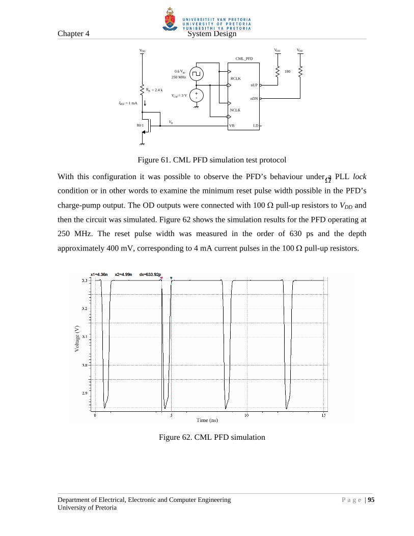
Chapter 4 System Design
Department of Electrical, Electronic and Computer Engineering P a g e | 95 University of Pretoria
CML_PFD
+-
0.6 Vpp
250 MHz RCLK
VB
NCLK
VDD VDD
nUP
nDN
100
VB80/1
VDD
= 1 mA
R = 2.4 kB
= 3 VVCM
IREF
LD
Figure 61. CML PFD simulation test protocol
With this configuration it was possible to observe the PFD’s behaviour under a PLL lock
condition or in other words to examine the minimum reset pulse width possible in the PFD’s
charge-pump output. The OD outputs were connected with 100 pull-up resistors to VDD and
then the circuit was simulated. Figure 62 shows the simulation results for the PFD operating at
250 MHz. The reset pulse width was measured in the order of 630 ps and the depth
approximately 400 mV, corresponding to 4 mA current pulses in the 100 pull-up resistors.
Figure 62. CML PFD simulation
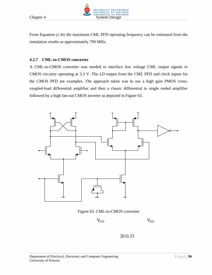
Chapter 4 System Design
Department of Electrical, Electronic and Computer Engineering P a g e | 96 University of Pretoria
From Equation (2.36) the maximum CML PFD operating frequency can be estimated from the
simulation results as approximately 790 MHz.
4.2.7 CML-to-CMOS converter
A CML-to-CMOS converter was needed to interface low voltage CML output signals to
CMOS circuitry operating at 3.3 V. The LD output from the CML PFD and clock inputs for
the CMOS PFD are examples. The approach taken was to use a high gain PMOS cross-
coupled-load differential amplifier and then a classic differential to single ended amplifier
followed by a high fan-out CMOS inverter as depicted in Figure 63.
Figure 63. CML-to-CMOS converter

Chapter 4 System Design
Department of Electrical, Electronic and Computer Engineering P a g e | 97 University of Pretoria
4.2.7.1 CML-to-CMOS converter simulation
Circuit operation was verified by simulation up to 500 MHz with a 0.6 Vpp CML clock input,
as depicted in Figure 64. The high bandwidth was deemed necessary, to minimise jitter,
especially for the clock signals feeding the CMOS PFD. The CMOS PFD is discussed in
section 4.3.4.
+-
0.6 Vpp
500 MHz
VB80/1
VDD
= 1 mA
R = 2.4 kB
= 3 VVCM
IREF
CML_2_CMOS
VB
In Out
Figure 64. CML-to-CMOS simulation test protocol
Figure 65 shows the simulation results with a 360 ps propagation delay measured.
Figure 65. CML to CMOS simulation

Chapter 4 System Design
Department of Electrical, Electronic and Computer Engineering P a g e | 98 University of Pretoria
4.3 CMOS SUBSYSTEMS
All CMOS subsystems were realized by using a combination of standard digital libraries from
the AMS C35 process. Some building blocks required for the synthesizer IC were however not
standard and had to be designed. These non-standard blocks are now discussed.
4.3.1 Binary adders and subtractors
Binary adders and subtractors are required in the building blocks for the pulse-swallow control
and programmable accumulator blocks. Binary adders perform the A+B math function. The
easiest way to construct an adder is to use a standard full adder (FA) block in cascade. A full
adder performs the binary addition of two bits and a carry in bit. The output is the sum bit and
a carry out bit. The logic diagram for a full adder is depicted in Figure 66.
Figure 66. Full adder logic diagram
Full adders are however part of the AMS standard digital libraries and only the multi-bit
binary adders need to be constructed. The required binary adder, utilizing cascaded full
adders, is known as a ripple carry adder (RCA). Figure 67 depicts a 4-bit adder example with
a general adder symbol.

Chapter 4 System Design
Department of Electrical, Electronic and Computer Engineering P a g e | 99 University of Pretoria
Figure 67. 4-bit binary adder: (a) Symbol, (b) FA implementation
Binary subtractors are also constructed from binary adders. The expression B-A can be written
as B + (-A) = B + (2’ complement of A). The 2’ complement of A is obtained by inverting A
and adding a “1”. The “1” is normally added to the adder’s carry input port. Figure 68 depicts
a typical 4-bit subtractor and a general subtractor symbol.
Figure 68. 4-bit binary subtractor: (a) Symbol, (b) FA implementation
4.3.2 Pulse-swallow control logic
In this dissertation a pulse-swallow divider structure is used, therefore the A and B-counter
values need to be calculated for every N value. The prescaler used in the synthesizer IC is a
2/3-prescaler, which in turn defines the values of the A and B-counters. From section 2.1.3.3
and Equation (2.30) the A and B-counters are calculated as follows:
)2( PAPBN (4.11)
2
N
P
NB (4.12)
(where x denotes the integer part of x )
PBNA (the remainder of the division) (4.13)

Chapter 4 System Design
Department of Electrical, Electronic and Computer Engineering P a g e | 100 University of Pretoria
In digital terms the implementation of Equations (4.12) and (4.13) are simple.
A divide by two operation is a binary right-shift operation and the remainder of this divide by
two operation is the bit shifted away. With a 4-bit B-counter and a 6-bit N value, Equations
(4.12) and (4.13) become:
1..40..3 NB (4.14)
00 NA (4.15)
The specific implementation of the 4-bit B-counter requires that the value calculated be
decremented by one. Equation (4.14) then becomes Equation (4.16) :
11..50..3
12
NB
NB
(4.16)
Figure 69 then shows the implementation for the calculation of the 4-bit B-counter and 1-bit
A-counter values:
MUX0
1SEL
6
5
6
B
A
B-A
C
Diff
“1”
N1[5..1]
5
4
N1[0]
N[0]A0
B[3..0]
N[5..0]
B
A
B-A
C
Diff
“1”
N/2 - 1
MUX0
1SEL
44
(N+1)/2 - 1
N1[5..0]
A
B
A+B
C
Sum
“1”
6N+1
“N+1” pulse
N[5..1]

Chapter 4 System Design
Department of Electrical, Electronic and Computer Engineering P a g e | 101 University of Pretoria
Figure 69. Pulse-swallow control
4.3.2.1 Fractional-N calculation delays
With a fractional-N divider topology the fractional accumulator will provide an overflow or
“N+1” signal. This signal is then used to select a divider value one higher than the existing
value. To minimise additional calculation delays, the calculations for the N and N+1 scenarios
are done simultaneously and the results are multiplexed by the “N+1” or accumulator
overflow signal. This concurrent calculation is also depicted in Figure 69. The N+1 addition is
done with a 6-bit binary adder.
4.3.3 Programmable modulus accumulator
In a fractional-N PLL an accumulator is needed to alter the divide ratio between N and N+1.
This is done by adding the required fractional part for every clock cycle to the existing sum or
result. When the sum is equal or greater than the required modulus, the accumulator indicates
an overflow condition and the result then becomes the difference between the sum and the
modulus. Digitally speaking, the easiest way to construct an accumulator is to use a modulus-2
type, implying any power-of-two 2n, such as a MOD16 or MOD256, etc. This employs a
standard binary adder where the output is clocked back to the adder input. The overflow
indicator simply becomes the carry out bit of the adder.
A modulus-2 type or a fixed modulus accumulator however puts a limit on the value of the
reference frequency used. The frequency resolution of a fractional-N PLL, is defined in
Equation (2.34) as MOD
fFreq ref
res . For a certain frequency resolution required, the reference
frequency will then also be fixed. This characteristic is not attractive in a synthesizer
architecture where industry standard reference frequencies are used, such as 10 MHz or
100 MHz. For this reason a programmable modulus accumulator is proposed as depicted in
Figure 70.

Chapter 4 System Design
Department of Electrical, Electronic and Computer Engineering P a g e | 102 University of Pretoria
DQ
Q CLK
A
B
B
A
B-A
A+B
C
Diff
C
Sum
MOD
FRAC
Overflow
Result
CLK
Sum
MUX0
1SEL
DFF
Figure 70. Programmable modulus accumulator
As described earlier the accumulator operates by adding the required numerator fractional part
FRAC every clock cycle to the existing sum or result. When the sum is greater or equal than
the required modulus MOD, the accumulator indicates an overflow condition and the result
becomes the difference between the sum and the modulus. Otherwise the result is just the sum.
The different results are multiplexed by the overflow condition as shown in Figure 70. The
overflow condition then later controls the N or N+1 divider selection. The accumulator
implemented in this dissertation was a 6-bit version with a modulus range of (1 ≤ MOD ≤ 63).
Practically the accumulator was implemented with 7-bits to accommodate overflows in the
adder and subtractor.
4.3.3.1 Maximum accumulator clock frequency
The maximum accumulator clock frequency was estimated by accounting for all the
propagation delays in the digital blocks making up the accumulator. Equation (4.17) calculates
the total number of digital or gate delays Ndelays as sixteen.
16 1 1 7 7 DFFMUXbitssubtractorbitsadderdelaysN (4.17)
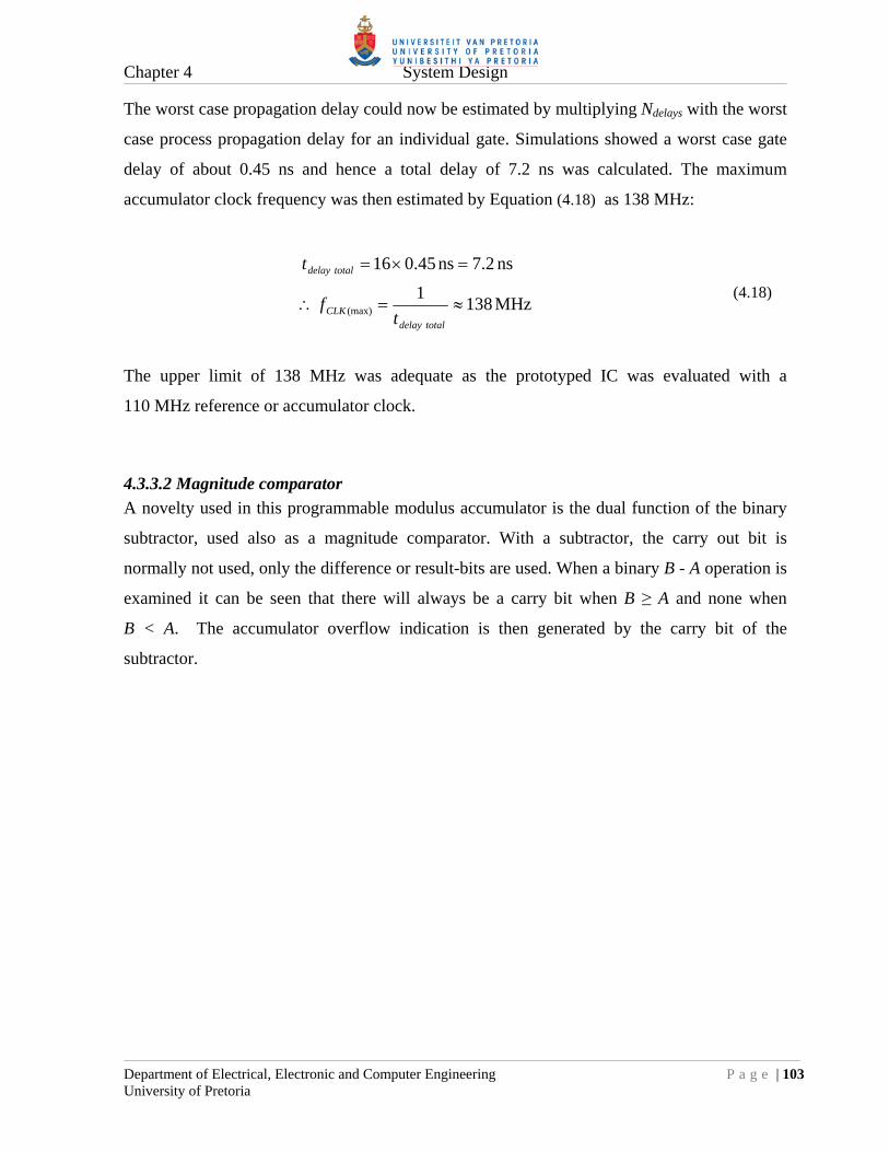
Chapter 4 System Design
Department of Electrical, Electronic and Computer Engineering P a g e | 103 University of Pretoria
The worst case propagation delay could now be estimated by multiplying Ndelays with the worst
case process propagation delay for an individual gate. Simulations showed a worst case gate
delay of about 0.45 ns and hence a total delay of 7.2 ns was calculated. The maximum
accumulator clock frequency was then estimated by Equation (4.18) as 138 MHz:
MHz 1381
ns 7.2ns 0.4516
(max)
totaldelayCLK
totaldelay
tf
t
(4.18)
The upper limit of 138 MHz was adequate as the prototyped IC was evaluated with a
110 MHz reference or accumulator clock.
4.3.3.2 Magnitude comparator
A novelty used in this programmable modulus accumulator is the dual function of the binary
subtractor, used also as a magnitude comparator. With a subtractor, the carry out bit is
normally not used, only the difference or result-bits are used. When a binary B - A operation is
examined it can be seen that there will always be a carry bit when B ≥ A and none when
B < A. The accumulator overflow indication is then generated by the carry bit of the
subtractor.

Chapter 4 System Design
Department of Electrical, Electronic and Computer Engineering P a g e | 104 University of Pretoria
4.3.4 CMOS PFD
For research benchmarking purposes both a CML and CMOS PFD were designed. The output
4 mA OD interface of the CMOS PFD was kept the same as the CML PFD. Off-chip loop
filter circuitry could then be shared for both PFDs. This will become evident in chapter 5. In
addition to a standard PFD design, the reset delay in this CMOS PFD was made selectable by
a multiplexer. The delays were implemented using cascaded buffers, each contributing a ∆τ
delay. The additional delays can be used to accommodate slower charge-pumps. Figure 71
then shows the CMOS PFD implemented in this dissertation.
Figure 71. CMOS PFD implementation
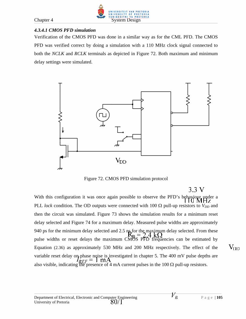
Chapter 4 System Design
Department of Electrical, Electronic and Computer Engineering P a g e | 105 University of Pretoria
4.3.4.1 CMOS PFD simulation
Verification of the CMOS PFD was done in a similar way as for the CML PFD. The CMOS
PFD was verified correct by doing a simulation with a 110 MHz clock signal connected to
both the NCLK and RCLK terminals as depicted in Figure 72. Both maximum and minimum
delay settings were simulated.
Figure 72. CMOS PFD simulation protocol
With this configuration it was once again possible to observe the PFD’s behaviour under a
PLL lock condition. The OD outputs were connected with 100 pull-up resistors to VDD and
then the circuit was simulated. Figure 73 shows the simulation results for a minimum reset
delay selected and Figure 74 for a maximum delay. Measured pulse widths are approximately
940 ps for the minimum delay selected and 2.5 ns for the maximum delay selected. From these
pulse widths or reset delays the maximum CMOS PFD frequencies can be estimated by
Equation (2.36) as approximately 530 MHz and 200 MHz respectively. The effect of the
variable reset delay on phase noise is investigated in chapter 5. The 400 mV pulse depths are
also visible, indicating the presence of 4 mA current pulses in the 100 pull-up resistors.

Chapter 4 System Design
Department of Electrical, Electronic and Computer Engineering P a g e | 106 University of Pretoria
Figure 73. CMOS PFD simulation - minimum delay
Figure 74. CMOS PFD simulation – maximum delay

Chapter 4 System Design
Department of Electrical, Electronic and Computer Engineering P a g e | 107 University of Pretoria
4.3.5 SPI interface
To save in IC pin count, a serial data interface was chosen. A popular industry standard is the
serial peripheral interface (SPI) bus. It was initially named by Motorola® and since adopted
by many other IC vendors. A SPI bus is then also used in this dissertation to program the
proposed synthesizer IC. It is a double buffered interface consisting of a serial clock line
SCLK, a serial data line SDAT and a latch-enable LE line. All relevant settings are serialised
into a single 20-bit word and activated or loaded by a rising edge on the LE signal. A shift
register was implemented on-chip to decode the serial word.
Figure 75 depicts the timing waveform and the sequence of the control bits.
Figure 75. SPI timing waveform
The 20-bit serial word consists of two CMOS PFD delay bits DEL[1..0], six modulus bits
M[5..0], six fractional bits F[5..0] and six N-divider bits N[5..0]. With this composition all
aspects in the fractional-N synthesizer IC can be programmed in a single write transaction.

Chapter 4 System Design
Department of Electrical, Electronic and Computer Engineering P a g e | 108 University of Pretoria
4.4 FLOOR PLAN
Figure 76 depicts the final layout for the synthesizer IC as used in this dissertation and has
dimensions of 3150 x 2180 µm2.
3150 µm
2180 µm
CMOS PFD
CML 4-bit counter
CML 2/3-prescaler CML PFD
CMOSCTRL
CML Ref CLK Amp
Figure 76. Prototyped IC floor plan
All major subsystems have been outlined and indicated. It is evident that the LUT based CML
4-bit counter takes up the majority of the area. As mentioned before, large ground metal areas
have been incorporated into the design to assist in minimising ground differences with current
mirrors and to aid with heat transfer to the perimeter of the chip. Each subsystem was
allocated its own VDD pad or set of VDD pads. Where high power supply currents were
expected, such as with the CML 4-bit counter, additional VDD pads were added to assist in pad
and bonding wire current sharing. In general for every VDD pad an equivalent GND pad was
added to cater for ground return paths in a specific subsystem.

CHAPTER 5: SIMULATION AND MEASUREMENT RESULTS
This chapter documents the system simulation and measurements results. As was stated earlier
two IC prototyping cycles were done. The first being the CML 2/3-prescaler and last the
complete fractional-N synthesizer IC. Many of the IC subsystems were simulated and proven
correct by design in chapter 4. This chapter then only focuses on the overall performance of
the ICs. The key performance parameters are the operating frequency, in-band phase noise and
fractional spurious response. Each prototyped IC is evaluated separately.
5.1 PROTOTYPED CML 2/3-PRESCALER
The objective with the prototyped CML 2/3-prescaler was to determine whether the research
methodology, assumptions and initial simulations done for the 0.35 µm technology were
correct, especially with regard to the maximum operating frequency. This would then serve as
a basis for completing the final low noise fractional-N synthesizer IC. Figure 77 shows the IC
die photograph with thermo-sonic bonding wires visible and Figure 78 a zoomed version.
Figure 77. Prototyped CML 2/3-prescaler IC die photograph

Chapter 5 Simulation and Measurement Results
Department of Electrical, Electronic and Computer Engineering P a g e | 110 University of Pretoria
Figure 78. Zoomed prototyped CML 2/3-prescaler IC die photograph
5.1.1 Test setup and general measurements
The primary objective with the CML 2/3-prescaler prototype IC is to determine the maximum
operating frequency. This is done by sweeping the input frequency and amplitude with a
signal generator and then observing the output with a spectrum analyzer. These results are
discussed in section 5.1.2. The general setup for evaluating the CML 2/3-prescaler is depicted
in Figure 79.
Figure 79. Prototyped CML 2/3-prescaler IC test setup
Chapter 5 Simulation and Measurement Results
Department of Electrical, Electronic and Computer Engineering P a g e | 111 University of Pretoria
From section 4.2.1.4 the internal IC reference current source is set to 1 mA by RB = 2.2 k
and a 1 µF capacitor was added for decoupling to the VB pin. The differential input section is
DC blocked by 1 nF capacitors and shunted with a 56 resistor to provide an approximate
50 impedance for the signal generator. The divide ratio is fixed at ÷3 by strapping the MC
pin to VDD. Current consumption and polyresistor measurements are discussed next.
5.1.1.1 Current consumption
The simulated current consumption of the prescaler formed part of the simulation results
obtained in section 4.2.3.5 and is compared with the actual measured value in TABLE XI:
TABLE XI
CML 2/3-PRESCALER CURRENT CONSUMPTION
Simulated Measured Deviation
29 mA 33 mA 13.8 %
The measured 33 mA compares well with the simulated 29 mA current consumption.
5.1.1.2 Polyresistor tolerances
As mentioned in section 4.2.5 the IC polyresistor tolerances can be verified by measuring the
500 input polyresistor with an ohm meter as highlighted in TABLE XII:
TABLE XII
POLYRESISTOR TOLERANCES
Designed Measured Deviation
500 420 -16 %
The -16 % deviation measured is however within the process tolerance ±20 % [50]. This
deviation for on-chip designed polyresistors could cause potential malfunctioning of CML
circuits if they were not designed for such high tolerances. This was then one of the reasons
why the CML output voltage swing was chosen higher than the process threshold voltage VTH
in chapter 4.

Chapter 5 Simulation and Measurement Results
Department of Electrical, Electronic and Computer Engineering P a g e | 112 University of Pretoria
5.1.2 Input sensitivity
The measured input sensitivity graph, Figure 80, displays the behaviour of the
CML 2/3-prescaler over frequency, indicating the maximum and minimum input levels and
operating frequencies. From this graph the “window” of operation can be determined. From
section 4.2.5 the maximum input level was limited to +10 dBm, as this was the power
restriction on the internal 500 input polyresistor.
0 500 1000 1500 2000 2500 3000-40
-35
-30
-25
-20
-15
-10
-5
0
5
10
15
Frequency (MHz)
Lev
el (
dBm
)
Maximum levelMinimum level
Figure 80. CML 2/3-prescaler input sensitivity graph
The maximum operating frequency was seen to be 2.7 GHz and proved to be better than the
worst case simulated 2.5 GHz as obtained in section 4.2.3.5. Visible in Figure 80 is a
“self resonant” frequency of 2.35 GHz which can in a way be explained by the low pass
resonant peaking of the combination of the IC package lead inductance, bonding wire
inductance, bonding pad capacitance and input MOSFET capacitance. This resonant effect is
not necessarily undesirable but will cause the IC to oscillate at this frequency if no input signal
is applied. Overall the performance of the CML 2/3-prescaler was satisfactory and it was
concluded that proceeding to the final low noise synthesizer IC design would pose less risk.

Chapter 5 Simulation and Measurement Results
Department of Electrical, Electronic and Computer Engineering P a g e | 113 University of Pretoria
5.2 PROTOTYPED FRACTIONAL-N SYNTHESIZER IC
With the prototyped synthesizer IC it was possible to evaluate the limits of the 0.35 µm
CMOS technology used and the topology of the synthesizer IC itself. Figure 81 shows the die
photograph with ultra-sonic bonding wires of the actual low noise fractional-N synthesizer IC.
Figure 81. Zoomed prototyped IC die photograph
Location of the individual subsystems can be obtained by comparing Figure 81 with
Figure 76. Some additional zoomed pictures of individual subsystems are presented in
Appendix B.

Chapter 5 Simulation and Measurement Results
Department of Electrical, Electronic and Computer Engineering P a g e | 114 University of Pretoria
5.2.1 Evaluation PCB
To evaluate the prototyped IC a complete frequency synthesizer system or infrastructure had
to be designed around the IC. This included a high voltage BJT charge pump, loop filter,
VCO, external ÷4 prescaler and crystal reference oscillator as depicted in Figure 82. The
prototyped IC was controlled or programmed via SPI by a graphical user interface (GUI) as
presented in Appendix C.
VCOLoop filter
4423.2 MHz
4423.2 MHz
1105.8 MHz
+3.3 V
÷4
BJT CP
+12 V
-5 V
nUP
nDN
Prescaler
Splitter
Jumpers
Jumpers
Proto IC
VCO
SDAT
SCLK
LE
Ref
SPI
110.58 MHz
+3.3 V
CMOS nUP
CML nUP
CMOS nDN
CML nDN
+3.3 V
VBVDD
2.2 k
GNDNDIV
Test Point
RB
Figure 82. Evaluation PCB block diagram
Many of the components chosen were due to their availability at GEW. This is especially true
for the 110.58 MHz low noise crystal reference oscillator and the 4.4 GHz VCO. The primary
objective was to measure the in-band phase noise performance of the prototyped IC. As
mentioned in chapter 3, the low division architecture incorporated into the IC design made it
difficult to measure phase noise accurately with a standard high performance spectrum
analyzer. For this reason an external off the shelf low noise ÷4 prescaler was added in the PLL
feedback path, to amplify the in-band output phase noise by another 12 dB. The total division
ratio was the product of the external prescaler setting and the programmed N-divider value of
the prototype IC. The other research objective was to benchmark the two types of PFDs. Wire
jumpers were used to select between the CMOS or CML PFD as indicated in Figure 82.

Chapter 5 Simulation and Measurement Results
Department of Electrical, Electronic and Computer Engineering P a g e | 115 University of Pretoria
The complete circuit diagram of the evaluation PCB can be found in Appendix A and a
photograph of the evaluation PCB is shown next in Figure 83.
SPI control
4.4 GHz VCO
Loop filter and fractional spur compensation
High voltage BJT charge pump
110.58 MHzcrystal reference
-5 V generator
+3.3 V low noise regulator
QFN-56 prototype IC
+5 V low noise regulator
External÷4 prescaler
+12 V input
PFD selection
Figure 83. Evaluation PCB photograph
Indicated on the photograph are the different components making up the complete evaluation
circuit. The PCB is 0.5 mm thick consisting of conventional FR4 dielectric material and two
copper layers, one being a uniform solid ground plane at the bottom. A single +12 V supply
was used as input and all the other required voltages were derived from this. Dedicated low
noise regulators were used on the +3.3 V and +5 V voltages. Light emitting diodes (LEDs)
were used to indicate CML PFD and CMOS PFD lock detect outputs.

Chapter 5 Simulation and Measurement Results
Department of Electrical, Electronic and Computer Engineering P a g e | 116 University of Pretoria
5.2.1.1 High voltage BJT charge pump
As was stated earlier an active OPAMP based loop filter would introduce additional out-band
phase noise. A passive loop filter was thus desirable. The problem was that the on-chip PFD
charge pumps only had a maximum voltage swing of +3.3 V, which would be inadequate for a
wide tuning range VCO. The solution was to mirror the on-chip PFD current pulses off-chip
with high voltage BJT mirrors, creating a high voltage charge pump circuit as depicted in
Figure 84.
BCM846
-5V
BCM856
+12V
BCM856
BCM856
BCM846
-5V
nUP
nDN
VDD VDD
VDD VDD
R R R R
R R
R R
R R
CPi
Figure 84. High voltage low noise BJT charge pump
The BJT current mirrors are modified Widlar current mirrors [53] where each transistor in a
mirror has the same emitter resistor value. This ensures that the input and output currents, of a
current mirror pair, are exactly the same. Commercially available high voltage (VCEO = 65 V)
NPN and PNP matched transistor pairs (BCM846 and BCM856 from Infineon®) were used
and the supply rail was set at +12 V. A higher rail voltage could be used if the VCO required

Chapter 5 Simulation and Measurement Results
Department of Electrical, Electronic and Computer Engineering P a g e | 117 University of Pretoria
it. The emitter resistors were set at 10 for the +3.3 V rail mirrors and 270 for the +12 V
and -5 V rail mirrors respectively. This prevented destructive high voltage failure of the
transistors if a short circuit should present itself somewhere.
5.2.2 Power consumption
The simulated current consumption of the prototyped IC formed part of the simulation results
obtained in section 5.2.3.1. Each subsystem in the IC was assigned its own VDD rail and a
subsequent power pin on the IC package. This simplified current measurements for each
subsystem and provided access for circuit debugging. A 1 series resistor was included to all
individual IC power pins on the evaluation PCB. Current consumption was obtained by
directly measuring the voltage across each 1 resistor with a multi-meter. These 1 resistors
are visible on the schematics of the evaluation PCB in Appendix A. TABLE XIII summarises
the power consumption.
TABLE XIII
POWER AND CURRENT CONSUMPTION
Block Simulated (mA) Measured (mA) Power (mW)
CML Prescaler 32 30.8 102
CML A and B Counters 130 129.5 427
CML PFD 35 35.4 117
CMOS PFD 15 16.6 55
CMOS Control 3 2.9 10
Total 215 215.2 710
A total DC power consumption of 710 mW was noted. It is also clear from TABLE XIII that the
current consumption simulations were good estimates to the actual measured values. As
expected, the biggest power consumers were the CML A and B-counters.

Chapter 5 Simulation and Measurement Results
Department of Electrical, Electronic and Computer Engineering P a g e | 118 University of Pretoria
5.2.3 Input sensitivity
One of the primary performance criteria of the prototyped synthesizer IC is the maximum
operating frequency. This is done with the input sensitivity test. The maximum operating
frequency was first estimated by simulation.
5.2.3.1 Simulation
Continuing from chapter 4, the maximum worst case operating frequency was simulated to be
in the order of 2.3 GHz. Figure 85 depicts the simulation setup for the combined internal CML
6-bit pulse-swallow divider, consisting of the CML 2/3-prescaler, A and B counters and the
CMOS pulse-swallow control. A divide ratio of N=11 was used.
Q
CML 4-bit counterVB
CLK Q
LOAD
CML 2/3-prescaler
MC
VB
VCO IN
QA
VB
0.6 Vpp 56
100 pF
100 pF
VDD
QB
Q
N=’11'
B0B1B2B3
LOAD
CLK
A0
VB
VB
VB80/1
VDD
= 1 mA
R = 2.4 kB
IREF
CML 1-bit counter
A0 B0B1B2B3
N0N1N2N3N4N5
CMOS Pulse-swallow control “N+1”
0.05 - 2.3 GHz
A
B
2/3
Figure 85. CML 6-bit pulse-swallow divider simulation setup
Visible in Figure 86 are the simulation results for a 2.3 GHz input signal. The 209.09 MHz
main divider output and the CML 2/3-prescaler output are shown. Operation of the
2/3-prescaler is demonstrated by examining the lower graph in Figure 86 where the prescaler
output alternates between 1.15 GHz (÷2) and 766.67 MHz (÷3), as set by the MC input.

Chapter 5 Simulation and Measurement Results
Department of Electrical, Electronic and Computer Engineering P a g e | 119 University of Pretoria
Figure 86. CML 6-bit pulse-swallow divider simulation results
5.2.3.2 Measurements
Input sensitivity measurements, for the prototyped IC, were done in a similar fashion as for the
prototyped CML 2/3-prescaler, by sweeping the input frequency and amplitude with a signal
generator and then observing the output on the NDIV test pin with a spectrum analyzer. The
NDIV pin is a buffered output of the main pulse-swallow N-divider. On the evaluation PCB
the input was for the moment disconnected from the external ÷4 prescaler and connected to
the output of the signal generator as depicted in Figure 87.
SPI
Figure 87. Prototyped IC input sensitivity test setup

Chapter 5 Simulation and Measurement Results
Department of Electrical, Electronic and Computer Engineering P a g e | 120 University of Pretoria
0 500 1000 1500 2000 2500 3000-35
-30
-25
-20
-15
-10
-5
0
5
10
Inpu
t lev
el (
dBm
)
Frequency (MHz)
2/3-prescalerSynthesizer IC
Figure 88. Prototyped IC input sensitivity graph
Figure 88 displays the results obtained. Different N-divider values were used during the test to
obtain an average output frequency of around 100 MHz. The results were somewhat
disappointing as it indicated a maximum N-divider operating frequency of 1.6 GHz and not
around 2.3 GHz as estimated. By overlaying the sensitivity graph of the prototyped CML
2/3-prescaler on Figure 88, it can be seen that the two profiles are similar. The only difference
being the amplitude offset which can be explained by the fact that the old prescaler design
used 40 µm MOSFETs, in the cascaded input amplifier, and the new design 80 µm MOSFETs.
This was done to improve the input sensitivity which is evident.
The only conclusion that can be drawn from Figure 88 is that the internal CML 4-bit counter is
not fast enough. When examining the floor plan of the IC, as in Figure 76, it is clear that the
CML 4-bit counter takes up most of the space. It is possible that the simulations did not
accurately model the large interconnect distances and associated capacitances and inductances.
This could all be attributed to the unaccounted bandwidth restriction.

Chapter 5 Simulation and Measurement Results
Department of Electrical, Electronic and Computer Engineering P a g e | 121 University of Pretoria
5.2.4 Phase noise measurements
Phase noise measurements were done at a carrier frequency of 4.4232 GHz where the VCO
was locked to a 110.58 MHz reference giving a total N-division ratio of 40. Initially the
measurements were done with a 100 kHz loop bandwidth, but this proved to be too narrow as
the thermal noise floor of synthesizer IC was still not exposed. A second set of measurements
were then done with a 500 kHz loop bandwidth which did expose the thermal noise floor.
With both sets of measurements, the CML PFD and CMOS PFD were benchmarked against
each other. The CMOS PFD was benchmarked with a minimum reset delay setting and a
maximum delay setting.
To put this 0.35 µm CMOS research in context, the prototyped synthesizer IC was also
benchmarked against a high performance, commercially available, GaAs HBT device. The
HMC440 device [10] from Hittite Microwave Corporation® served as a reference as it was
used in a circuit with exact the same divide ratio, reference frequency source, loop bandwidth,
loop filter architecture and VCO.
5.2.4.1 100 kHz loop bandwidth
The loop bandwidth can be manipulated by the components making up the passive loop filter.
By using the formulas presented in sections 2.1.6.1 and 2.1.6.3, the passive loop filter
components for a 100 kHz loop bandwidth were calculated by using the following input
parameters as indicated in TABLE XIV.
TABLE XIV
LOOP FILTER CALCULATION INPUT PARAMETERS
Parameter Value Motivation
Phase detector gain: 2
mA 4
2 CP
P
IK By design ICP = 4 mA
VCO gain: MHz/V 16 2 2 VCOV KK KVCO =16 MHz/V from VCO CRO4400 datasheet
Phase margin: 68m 68º will give less noise peaking
Loop bandwidth: kHz 1002 p 100 kHz required for test
N-divider value 40N Required for output frequency

Chapter 5 Simulation and Measurement Results
Department of Electrical, Electronic and Computer Engineering P a g e | 122 University of Pretoria
The rounded calculated values, as used on the evaluation PCB, are displayed in Figure 89.
Figure 89. Loop filter - 100 kHz loop bandwidth
Figure 90 summarises the 100 kHz loop bandwidth phase noise measurements.
102
103
104
105
106
-130
-125
-120
-115
-110
-105
-100
-95
-90
Frequency (Hz)
SSB
pha
se n
oise
(dB
c/H
z)
CMOS PFD (Delay = maximum)CMOS PFD (Delay = minimum)CML PFDGaAs HBT reference (HMC440)
Figure 90. SSB phase noise results - 100 kHz loop bandwidth
From Figure 90 a limitation of the spectrum analyzer used is observed. All measurements
below a 1 kHz offset tend to bundle together indicating a phase noise limitation of the

Chapter 5 Simulation and Measurement Results
Department of Electrical, Electronic and Computer Engineering P a g e | 123 University of Pretoria
spectrum analyzer at these low offsets. At higher offset frequencies the performance of the
spectrum analyzer is adequate to accurately measure the phase noise of the prototyped
synthesizer IC. What is clear from Figure 90 is the fact that the flicker noise of the CMOS
synthesizer IC dominates the spectrum. The thermal noise plateau has not been reached in any
of the measurements except for the HMC440 GaAs HBT reference device. In the case of the
GaAs HBT device the noise plateau was reached at an offset of 5 kHz with a value of
L( f ) = -113 dBc/Hz. One of the goals of this research is to determine the FOM which is only
applicable to the in-band noise plateau. For this reason it was decided to widen the loop
bandwidth so to expose the thermal noise floor. A loop bandwidth of 500 kHz was chosen.
5.2.4.2 500 kHz loop bandwidth
In a similar way, as for the 100 kHz loop bandwidth, the loop filter components for the
500 kHz loop bandwidth are displayed in Figure 91.
Figure 91. Loop filter - 500 kHz loop bandwidth
The culmination of phase noise results for this research is depicted in Figure 92. From this
graph it is seen that the in-band phase noise plateau is reached at an offset of 100 kHz, with a
value of L( f ) = -113 dBc/Hz for the CML PFD.
The FOM can be calculated for the CML PFD by using Equation (2.69):

Chapter 5 Simulation and Measurement Results
Department of Electrical, Electronic and Computer Engineering P a g e | 124 University of Pretoria
dBc/Hz 5 225.-
MHz) 58 10log(110.- 20log(40) - dBc/Hz 113-
log10log20
RfNfFOM L
102
103
104
105
106
-130
-125
-120
-115
-110
-105
-100
-95
-90
Frequency (Hz)
SSB
pha
se n
oise
(dB
c/H
z)
CMOS PFD (Delay = maximum)CMOS PFD (Delay = minimum)CML PFD
Figure 92. SSB phase noise results - 500 kHz loop bandwidth
At a 500 kHz offset some phase noise peaking is observed which can be due to the finite
bandwidth of the high voltage charge pump or the input capacitance of the VCO, thus
affecting the phase margin. What is clear from Figure 90 and Figure 92 is the differences in
technologies (HBT vs CMOS) and PFD implementations. The prototyped CMOS IC only
reaches the same noise floor (-113 dBc/Hz) as the GaAs HBT device at an offset of 100 kHz.
This is twenty times higher in offset frequency than the GaAs HBT device. Fortunately the
CML PFD has the same wideband noise floor as the GaAs HBT device. The CML PFD is
definitely superior to the CMOS PFD, even for the minimum delay case. The PFD phase noise
differences can possibly be explained by the reset pulse delay in all cases.

Chapter 5 Simulation and Measurement Results
Department of Electrical, Electronic and Computer Engineering P a g e | 125 University of Pretoria
From simulations in chapter 4 and Equation (2.37), the CMOS PFD had longer reset delays
and thereby allowing more charge-pump noise to accumulate, hence degrading the phase noise
performance. It is also possible that the CML-to-CMOS translator block is noisy.
5.2.5 Fractional spur compensation
Mentioned in chapter 2 was the fact that any fractional-N synthesizer IC would introduce
fractional and in addition reference boundary spurious signals to the output spectrum. In
conventional fractional-N topologies the fractional spurs are dithered away with higher order
ΣΔ modulators. This comes at the cost of increased in-band phase noise [1]. Up to date not
much can however be done on-chip for reference boundary spurs, to the author’s knowledge.
These spurs occur in a fractional-N topology where the loop bandwidth is normally much
larger than the frequency resolution of the synthesizer. A reference boundary spur will occur
when the output frequency is within a small offset from a multiple of the reference frequency.
If the offset frequency falls inside the PLL loop bandwidth the spurs will manifest themselves
at exactly the offset frequency on both sides of the carrier. Both fractional and reference
boundary spurs occur due to the non-linear behaviour of the PFD.
As the PFD causes these spurs, a way around this problem is to limit the tuning resolution to a
frequency step size way bigger than the loop bandwidth. An additional off-chip analogue filter
can then easily filter out the PFD’s fractional and reference boundary contributions. The
analogue filter may however adversely affect the PLL phase margin. It is best to choose the
frequency step size high enough to not disturb the phase margin for a given loop bandwidth.
Such an analogue filter can then be incorporated into an existing loop filter.
In the custom built 4.4 GHz synthesizer circuit, evaluating the prototyped IC, a fractional
modulus of 40 was used. A tuning resolution of 2.7645 MHz for a 110.58 MHz PLL reference
resulted. This implied that fractional spurs would occur on multiples of 2.7645 MHz. To
counter these spurs, an analogue fractional spur compensation network was implemented by a
set of cascaded LC notch filters. The notch filters took the form of parallel resonant traps
resonating at multiples or harmonics of 2.7645 MHz. The existing loop filter was then
modified as indicated in Figure 93.

Chapter 5 Simulation and Measurement Results
Department of Electrical, Electronic and Computer Engineering P a g e | 126 University of Pretoria
Figure 93. Modified passive loop filter - fractional spurious compensation
Moderate Q-factors were used for the traps as too high Qs would require the inductor and
capacitor values to be manually trimmed, to cater for component tolerances. The Q-factor for
an inductor is defined as the ratio of the reactance XL over the internal series resistance R:
R
Lf
R
XQ L 2
(5.1)
In any resonating LC circuit the total Q-factor will be limited by the element with the lowest
Q-factor. In this case it is the inductor. For the 2.76 MHz trap, a 22 µH inductor from
Coilcraft® (1812CS-223) was selected. This inductor had a rated Q-factor of 32 at 10 MHz.
A 150 pF capacitor was calculated to resonate with the inductor at 2.76 MHz. The 2nd
harmonic 5.52 MHz trap was designed with a 10 µH inductor and an associated 82 pF
capacitor to resonate. Exact implementation of the compensation network can be found in
Appendix A.
Shown on the next page are the measured effects of this compensation network.
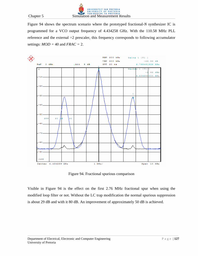
Chapter 5 Simulation and Measurement Results
Department of Electrical, Electronic and Computer Engineering P a g e | 127 University of Pretoria
Figure 94 shows the spectrum scenario where the prototyped fractional-N synthesizer IC is
programmed for a VCO output frequency of 4.434258 GHz. With the 110.58 MHz PLL
reference and the external ÷2 prescaler, this frequency corresponds to following accumulator
settings: MOD = 40 and FRAC = 2.
Figure 94. Fractional spurious comparison
Visible in Figure 94 is the effect on the first 2.76 MHz fractional spur when using the
modified loop filter or not. Without the LC trap modification the normal spurious suppression
is about 29 dB and with it 80 dB. An improvement of approximately 50 dB is achieved.

CHAPTER 6: CONCLUSION
This chapter concludes the research and summarises the results. The objective of this
dissertation was to research a collection of techniques, as applicable to high performance
synthesizer ICs, to push towards the noise and frequency limits of CMOS processes in general.
By doing this the performance of existing HBT synthesizer ICs could maybe be rivalled by a
low cost CMOS IC. The research was verified by implementing a low noise low division
(4 ≤ N ≤ 33) synthesizer IC in a reasonably low cost 0.35 µm CMOS process with a designed
operating frequency in the excess of 2 GHz. A fractional-N topology was also incorporated.
6.1 TECHNICAL SUMMARY AND CONTRIBUTION
A summary of all technical achievements and contributions are discussed next.
6.1.1 FOM
The low noise requirement was demonstrated with a FOM = -225 dBc/Hz at an offset
frequency of 100 kHz for a 0.35 µm CMOS process. This FOM is comparable to the best high
performance expensive SiGe and GaAs HBT devices out there.
6.1.2 CML low division high frequency divider
Due to the slow speed of 0.35 µm CMOS dividers (f < 500 MHz), consisting of standard
CMOS logic blocks, an all CML low division (4 ≤ N ≤ 33) high frequency divider was
designed and demonstrated. The divider was a 6-bit pulse-swallow divider consisting of a
2/3-precaler, 4-bit counter and a 1-bit counter. Although only practically operational at
1.6 GHz it was still a major improvement over standard CMOS dividers.
6.1.3 CML PFD
An all CML PFD was demonstrated with a maximum simulated comparison frequency of
790 MHz. It was also the CML PFD that achieved the low FOM = -225 dBc/Hz value. Part of
the CML design also required a resettable CML D-latch.
References
Department of Electrical, Electronic and Computer Engineering P a g e | 129 University of Pretoria
6.1.4 PFD reset delay effect
Demonstrated was the effect of a variable reset delay in a PFD circuit. Measured results
concurred with theory that the delay must be minimised to achieve a good FOM.
6.1.5 Programmable modulus accumulator
Many commercially available fractional-N synthesizer ICs fix the modulus value of the
fractional accumulator in hardware with some power-of-two 2n value. This eases digital
implementation. In this dissertation the modulus was implemented programmable
(1 ≤ MOD ≤ 63). A requirement in the programmable accumulator was a binary magnitude
comparator. This was implemented in a novel way by using the carry out bit of a standard
binary subtractor.
6.1.6 Power dissipation
A nominal IC power dissipation of 710 mW was observed. This is high in terms of
conventional CMOS terms but in comparison to many high performance GaAs HBT
synthesizer ICs (see TABLE I) it is a major improvement.
6.1.7 High voltage CP
A high voltage off-chip BJT charge-pump circuit was demonstrated for low out-band phase
noise operation with high gain wide tuning range VCOs.
6.1.8 Fractional spurious compensation network
An off-chip LC network was added to an existing passive loop filter to aid in the suppression
of fractional spurs. A 50 dB improvement was seen over the conventional loop filter
implementation.

References
Department of Electrical, Electronic and Computer Engineering P a g e | 130 University of Pretoria
6.2 RECOMMENDATIONS FOR FUTURE WORK
The results from this research are very promising and indeed it seems possible that well
designed low noise CMOS synthesizer ICs can rival GaAs HBT synthesizer ICs in many
areas. There are however a few suggestions and considerations for future work on this topic.
6.2.1 MOSFET flicker noise
The biggest obstacle for future work will be the inherently high flicker noise of any MOSFET
design. This is quite apparent in CML architectures. Figure 90 clearly illustrates the flicker
noise difference between the referenced GaAs HBT device and the prototyped IC. As a way
forward a RF phase noise simulator must definitely be used to optimise CML circuits for
phase noise. One such a simulator is SpectreRF® from the Virtuoso© Cadence Design
Systems suite. Additional methods could be further investigated to reduce flicker noise in
MOSFETs.
6.2.2 CML 4-bit counter architecture
The CML main divider proved operational to 1.6 GHz but not to 2.3 GHz as was simulated.
The CML 2/3-prescaler however was proven operational to 2.7 GHz. It was then concluded
from input sensitivity results that the LUT based CML 4-bit counter was at fault. The speed
deficiency of the counter is speculated to the large interconnect distances associated with the
design. It is then recommended that a standard more conventional synchronous counter
architecture be implemented as depicted in Figure 7. This implementation should have
reduced long distance interconnects.
6.2.3 SiGe HBT implementation
If a higher performance synthesizer IC is required and a moderate escalation in IC
manufacturing costs is acceptable, then a SiGe HBT design may be the solution. This research
contains a collection of low noise design techniques which can be made applicable to other IC
processes. A SiGe design will address many of the limitations associated with CMOS
processes, such as flicker noise and speed. CML circuits are particularly well suited for SiGe
HBT implementation.

References
Department of Electrical, Electronic and Computer Engineering P a g e | 131 University of Pretoria
REFERENCES
[1] D. Banerjee, “PLL Performance, Simulation, and Design”, National Semiconductor,
1998.
[2] I. Thompson and P.V. Brennan, “Phase noise contribution of the phase/frequency
detector in a digital PLL frequency synthesiser”, Proc.: IEE Circuits, Devices and
Systems, vol. 150, no. 1, pp.1-5, Feb. 2003.
[3] T.A.D. Riley, N.M. Filiol and J.Q. Du Kostamovaara, “Techniques for in-band phase
noise reduction in ΔΣ synthesizers”, IEEE Trans. on Circuits and Systems II: Analog
and Digital Signal Processing, vol. 50, no. 11, pp. 794-803, Nov. 2003.
[4] W. Rhee, B. Sup-Song and A.A. Ali, “A 1.1 GHz CMOS fractional-N frequency
synthesizer with a 2-b third-order ΔΣ modulator,” IEEE Jour. Solid-State Circuits, vol.
35, no. 10, pp. 1453-1460, Oct. 2000.
[5] S. Willingham, M. Perrott, B. Setterberg, A. Grzegorek, B. McFarland, “An integrated
2.5 GHz ΔΣ frequency synthesizer with 5 µs settling and 2 Mb/s closed loop
modulation,” Proc. of the International Solid-State Circuits Conf., San Francisco, pp.
200-201, Feb. 2000.
[6] ADF4002 datasheet, “400 MHz frequency synthesizer”, Analog Devices. Available:
http://www.analog.com.
[7] ADF4108 datasheet, “8.0 GHz PLL frequency synthesizer”, Analog Devices.
Available: http://www.analog.com.
[8] HMC700 datasheet, “8 GHz 16-Bit Fractional-N Synthesizer”, Hittite Microwave
Corporation. Available: http://www.hittite.com.
References
Department of Electrical, Electronic and Computer Engineering P a g e | 132 University of Pretoria
[9] HMC698 datasheet, “7 GHz integer-N synthesizer (N = 12 - 259)”, Hittite Microwave
Corporation. Available: http://www.hittite.com.
[10] HMC440 datasheet, “2.8 GHz Integer-N synthesizer (N = 2 - 32)”, Hittite Microwave
Corporation. Available: http://www.hittite.com.
[11] H. Hedayati, W. Khalil, B.M. Bakkaloglu, “A 1 MHz Bandwidth, 6 GHz 0.18 µm
CMOS Type-I Fractional-N Synthesizer for WiMAX Applications”, IEEE Jour. of
Solid-State Circuits, vol. 44, no. 12, pp. 3244-3252, Dec. 2009.
[12] M. Guermandi, E. Franchi, A.H. Gnudi, “A CMOS 90 nm 55 mW 3.4-to-9.2 GHz 12
Band Frequency Synthesizer for MB-OFDM UWB”, IEEE Microwave and Wireless
Components Letters, vol. 19, no. 11, pp. 752-754, Nov. 2009.
[13] F.M. Gardner, Phase lock techniques, Wiley, 1979.
[14] J. van de Vegte, Feedback Control Systems, 2nd ed., Prentice-Hall, 1990
[15] K. Shu and E. Sánchez-Siencio, CMOS PLL Synthesizers Analysis and Design, New
York, Springer, 2005.
[16] C.S. Vaucher, I. Ferencic, M. Locher, S. Sedvallson, U. Voegeli, Z. Wang, “A Family
of Low-Power Truly Modular Programmable Dividers in Standard 0.35 µm CMOS
Technology”, IEEE Jour. Solid-State Circuits, vol. 35, no. 7, pp. 1039-1045, Jul. 2000.
[17] HP Bench Briefs, May-Aug. 1977.
[18] C.A. Sharpe, “A 3-state phase detector can improve your next PLL design”, EDN, pp.
55-59, Sept. 1976.

References
Department of Electrical, Electronic and Computer Engineering P a g e | 133 University of Pretoria
[19] F.M. Gardner, “Charge-Pump Phase-Lock Loops,” IEEE Trans. on Communications,
vol. 28, pp. 1849-1858, Nov. 1980.
[20] M. Mansuri, D. Liu, C.K.K. Yang, “Fast Frequency Acquisition Phase-Frequency
Detectors for GSamples/s Phase-Locked Loops”, IEEE Jour. Solid-State Circuits, vol.
37, no. 10, pp. 1331-1334, Oct. 2002.
[21] J. Craninckx and M. Steyaert, Wireless CMOS Frequency Synthesizer Design, 1st ed.,
Kluwer, 1998.
[22] B. Razavi, Design of Analog CMOS Integrated Circuits, 1st ed., McGraw-Hill, 2001.
[23] W.O. Keese, “An analysis and performance evaluation of a passive filter design
technique for charge pump phase-locked loops”, National Semiconductor, Application
note AN-1001, May 1996.
[24] ADIsimPLL®, “PLL Design & Simulation for Analog Devices’s PLLs”, Analog
Devices. Available: http://www.analog.com.
[25] C.J. Grebenkemper, “Local Oscillator Phase Noise and its effect on Receiver
Performance,” Watkins-Johnson Company: Tech Note, vol. 8, no. 6, Nov./Dec. 1981.
[26] “Specifications and Measurement of Local Oscillator Noise in Integrated Circuit Base
Station Mixers”, Maxim Integrated Products, Application Note AN-2021, May 2003.
[27] Brannon B., “Sampled Systems and the Effects of Clock Phase Noise and Jitter”,
Analog Devices Application Note-AN756.
[28] P.R. Gray, P.J. Hurst, S.H. Lewis and R.G. Meyer, Analysis and design of analog
integrated circuits, 4th ed., Wiley, 2001.

References
Department of Electrical, Electronic and Computer Engineering P a g e | 134 University of Pretoria
[29] S. Haykin, Communication Systems, 2nd ed., Wiley, 1983.
[30] A.S. Sedra and K.C. Smith, Microelectronic Circuits, 5th ed., Oxford University Press,
2004.
[31] A. van der Ziel, Noise in Solid State Devices and Circuits, 1st ed., Wiley, 1986.
[32] S. Tedja, J. Van der Spiegel and H.H. Williams. “Analytical and Experimental Studies
of Thermal Noise in MOSFETs”, IEEE Trans. on Electron Devices, vol. 41, no. 11, pp.
2069-2075, Nov. 1994.
[33] F. Dulger, E. Sanchez-Sinencio and A. Bellaouar, “Design considerations in a
BiCMOS dual-modulus prescaler”, Proc.: IEEE Radio Frequency Integrated Circuits
(RFIC) Symposium, pp. 177-180, Philadelphia, 8-10 Jun. 2002.
[34] K.H. Lundberg, “Noise Sources in Bulk CMOS”, MIT papers.
http://web.mit.edu/klund/www/papers
[35] P. White, “Understanding Phase Noise From Digital Components in PLL Frequency
Synthesizers,” Applied Radio Labs: Design file DN006, December 2000.
[36] J. Rabye, Digital Integrated Circuits, Prentice Hall, 1996.
[37] M. Alioto and G. Palumbo, Model and Design of Bipolar and MOS Current-Mode
Logic (CML, ECL and SCL Digital Circuits), Springer, 2005.
[38] T. Kuboki, A. Tsuchiya and H. Onodera, “Low-Power Design of CML Drivers for On-
Chip Transmission-Lines”, IEICE Trans. on Electronics 2007 (E90-C), vol. 6, no. 1,
pp. 274-1281, 2007.

References
Department of Electrical, Electronic and Computer Engineering P a g e | 135 University of Pretoria
[39] S. Badel, I. Hatirnaz and Y. Leblebici, “Semi-automated design of a MOS current-
mode logic standard cell library from generic components”, Research in
Microelectronics and Electronics, 2005 PhD, vol. 2, pp. 155-158, July 2005.
[40] M.M. Green and U. Singh, “Design of CMOS CML circuits for high-speed broadband
communications”, Proc. of the 2003 IEEE International Symposium on Circuits and
Systems, vol. 2, pp. 204-207, Bangkok, 25-28 May 2003.
[41] M.T. Terrovitis and R.G. Meyer, “Noise in current-commutating CMOS mixers”, IEEE
Jour. Solid-State Circuits, vol. 34, no. 6, pp. 772-783, June 1999.
[42] E.J. Brauer and Y. Leblebici, “Sub-70 ps Full Adder in MOS Current-Mode Logic
Using 0.18μm CMOS Technology”, IASTED International Conf. Circuits, Signals, and
Systems, Clearwater Beach, 28 Nov.- 11 Dec. 2004.
[43] J. Twomey, “Designing analog and mixed-signal circuits on digital-CMOS processes”,
EDN, pp. 109-116, Aug. 2000.
[44] T.E. Kolding, “Compact Model Specification of RF MOSFET with DC and AC
Evaluations”, Technical Report R99-1005, RF Integrated Systems & Circuits (RISC)
group, Sept. 1999.
[45] H.D. Wohlmuth and D. Kehrer, “A high sensitivity static 2:1 frequency divider up to
27GHz in 120nm CMOS”, Proc. of the 28th European Solid-State Circuits Conf.
ESSCIRC 2002, pp. 823- 826, Florence, 24-26 Sept. 2002.
[46] H.D. Wohlmuth and D. Kehrer, “A 15 GHz 256/257 dual-modulus prescaler in 120 nm
CMOS”, Proc. of the 29th European Solid-State Circuits Conf. ESSCIRC 2003, pp. 77-
80, Estoril, 16-18 Sept. 2003.
References
Department of Electrical, Electronic and Computer Engineering P a g e | 136 University of Pretoria
[47] K.L.J. Wong, A. Rylyakov and C.K.K. Yang, “A broadband 44-GHz frequency divider
in 90-nm CMOS”, Proc. of the IEEE Compound Semiconductor Integrated Circuit
(CSIC) Symposium, pp. 196-199, Palm Springs, 30 Oct. - 2 Nov. 2005.
[48] C.H. Long and C.T.G. Leung, Low-Voltage CMOS RF Frequency Synthesizers,
Cambridge, Cambridge University Press, 2004.
[49] R.B. Staszewski and P.T. Balsara, All-Digital Frequency Synthesizer in Deep-
Submicron CMOS, Wiley, 2006.
[50] Austriamicrosystems, "0.35 µm CMOS C35 Process Parameters", ENG-182.
Available: http://www.austriamicrosystems.com.
[51] Tanner EDA Home Page. Tanner EDA. Available: http://www.tanner.com/EDA/
[52] Austriamicrosystems, "0.35 µm CMOS C35 Design Rules", ENG-183. Available:
http://www.austriamicrosystems.com.
[53] R.S. Widlar, “Some circuit design techniques for linear integrated circuits”, IEEE
Trans. on Circuit Theory, CT-12, 1968.
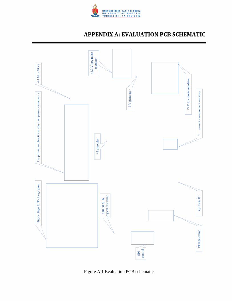
APPENDIX A: EVALUATION PCB SCHEMATIC
SPI
co
ntro
l
+5
V lo
w n
oise
reg
ulat
or
Loo
p fi
lter
and
frac
tion
al s
pur
com
pens
atio
nne
twor
k
110.
58 M
Hz
crys
tal r
efer
ence
PF
D s
elec
tion
4.4
GH
z V
CO
1 cu
rren
t mea
sure
men
t res
isto
rsQ
FN
-56
IC
+3.
3 V
low
noi
se
regu
lato
r
-5 V
gen
erat
or
÷4 p
resc
aler
Hig
h vo
ltag
e B
JT c
harg
e pu
mp
Figure A.1 Evaluation PCB schematic

APPENDIX B: PROTOTYPED IC PHOTOGRAPHS
Figure B.1 QFN Frame bonding wires with dedicated ground bonding visible

Appendix B Prototyped IC photographs
Department of Electrical, Electronic and Computer Engineering P a g e | 139 University of Pretoria
Figure B.2 CMOS control (left) and CML 2/3-prescaler (bottom right)

Appendix B Prototyped IC photographs
Department of Electrical, Electronic and Computer Engineering P a g e | 140 University of Pretoria
Figure B.3 Zoomed CML 2/3-prescaler

Appendix B Prototyped IC photographs
Department of Electrical, Electronic and Computer Engineering P a g e | 141 University of Pretoria
Figure B.4 Zoomed CML PFD (center) and reference clock amplifier (left)
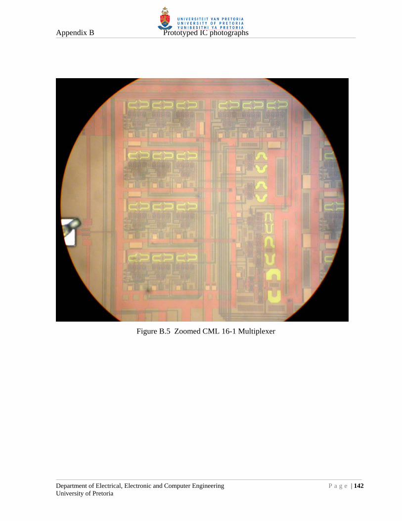
Appendix B Prototyped IC photographs
Department of Electrical, Electronic and Computer Engineering P a g e | 142 University of Pretoria
Figure B.5 Zoomed CML 16-1 Multiplexer

APPENDIX C: TEST GRAPHICAL USER INTERFACE (GUI)
Figure C.1 Test GUI used to control the prototyped IC