Embed Size (px)
Citation preview
Low intrinsic emittance in modern photoinjector brightness
Christopher M. Pierce ,* Matthew B. Andorf , Edmond Lu, Colwyn Gulliford ,Ivan V. Bazarov, and Jared M. Maxson
Cornell Laboratory for Accelerator-based Sciences and Education, Cornell University,Ithaca, New York 14853, USA
Matthew Gordon and Young-Kee KimUniversity of Chicago, Chicago, Illinois 60637, USA
Nora P. Norvell, Bruce M. Dunham , and Tor O. RaubenheimerSLAC National Accelerator Laboratory, Menlo Park, California 94025, USA
(Received 16 April 2020; accepted 16 June 2020; published 21 July 2020)
Reducing the intrinsic emittance of photocathodes is one of the most promising routes to improving thebrightness of electron sources. However, when emittance growth occurs during beam transport (forexample, due to space charge), it is possible that this emittance growth overwhelms the contribution of thephotocathode, and, thus, in this case source emittance improvements are not beneficial. Using multi-objective genetic optimization, we investigate the role intrinsic emittance plays in determining the finalemittance of several space-charge-dominated photoinjectors, including those for high-repetition-rate freeelectron lasers and ultrafast electron diffraction. We introduce a new metric to predict the scale ofphotocathode emittance improvements that remain beneficial and explain how additional tuning is requiredto take full advantage of new photocathode technologies. Additionally, we determine the scale of emittancegrowth due to point-to-point Coulomb interactions with a fast tree-based space-charge solver. Our resultsshow that, in the realistic high-brightness photoinjector applications under study, the reduction of thermalemittance to values as low as 50 pm=μm (1 meV mean transverse energy) remains a viable option for theimprovement of beam brightness.
DOI: 10.1103/PhysRevAccelBeams.23.070101
I. INTRODUCTION
Improving the brightness of space-charge-dominatedelectron sources will unlock a wealth of next-generationaccelerator physics applications. For example, the largestunit cell that may be studied with single-shot ultrafastelectron diffraction (UED) is limited by the beam’s trans-verse coherence length, which is determined by transverseemittance, at a high enough bunch charge to mitigate theeffects of shot noise in data collection. The study of proteindynamics with UED requires producing >1 nm scalecoherence lengths at more than 105 electrons and subpico-second pulse lengths at the sample location [1,2]. In anotherexample, the intensity of coherent radiation available to theusers of free electron lasers (FELs) is, in part, limited bybeam brightness. Beam brightness affects the efficiency,
radiated power, gain length, and photon energy reach ofFELs [3,4].Photoinjectors equipped with low intrinsic emittance
photocathodes are among the brightest electron sources inuse today. Peak brightness at the source is limited by twofactors: the electric field at the cathode and the photo-cathode’s transverse momentum spread. Several short-pulse Child-Langmuir-like charge density limits have beenderived for the photoemission regimes of relevance topractical photoinjectors. These current density extractionlimits make explicit the dependence of peak brightness onphotocathode parameters and the electric field [5–7].Depending on the aspect ratio of the bunch, the brightnesslimit is superlinear in the electric field and motivates thepush toward high accelerating gradient photoinjectors.Contemporary dc, normal-conducting rf (NCRF), andsuperconducting rf (SRF) photoelectron guns have peakaccelerating fields of the order of 10 MV=m [8–11] withvery high repetition rates (well above 1 MHz). At the costof duty factor, state of the art NCRF electron guns can offereven higher fields of the order of 100 MV=m [12], andrecent experimental results suggest the possibility ofpushing peak fields to nearly 500 MV=m for cryogenicallycooled accelerating structures [13–24].
Published by the American Physical Society under the terms ofthe Creative Commons Attribution 4.0 International license.Further distribution of this work must maintain attribution tothe author(s) and the published article’s title, journal citation,and DOI.
PHYSICAL REVIEW ACCELERATORS AND BEAMS 23, 070101 (2020)
2469-9888=20=23(7)=070101(13) 070101-1 Published by the American Physical Society

In this work, we characterize the intrinsic emittance atthe photocathode source via the mean transverse energy(MTE):
εC ¼ σx
ffiffiffiffiffiffiffiffiffiffiffiMTEmc2
r; ð1Þ
where σx is the laser spot size and m is the mass of theelectron. Here, it is clear that MTE plays the role of aneffective temperature of emission.Great progress is being made in the discovery of low-
MTE photocathodes which are expected to improve theusable brightness of photoinjectors. Because of the prac-tical trade-offs involved with photocathode choice, mostphotoinjectors today use materials with an MTE of around150 meV [25–28]. At the cost of quantum efficiency (QE),this MTE may be reduced by tuning the driving laser’swavelength. For example, in Cs3Sb and Cs:GaAs photo-cathodes, the lowest MTE that may be achieved viawavelength tuning at room temperature is nearly 35 and25 meV, respectively, but at 10−6 − 10−5 QE [29–31].Recent work has shown that the cryogenic cooling ofphotocathodes emitting at threshold can reduce MTE evenfurther, potentially down to single-digit meV MTEs [32].However, a natural question arises amid this progress inMTE reduction: In modern space-charge-dominated appli-cations, to what extent does MTE reduction actuallyimprove the final emittance?Even in the case of linear transport, 3D space-charge
effects lead to a transverse position-angle correlation whichvaries along the longitudinal coordinate and leads to aninflation of projected emittance that requires compensation[33–36]. The residual emittance after compensation is dueto nonlinear forces, from either space-charge or beam lineelements. Scaling laws exist to help estimate their effects[37,38]. In some cases, nonlinearity can cause phase spacewave breaking in unevenly distributed beams that is asource of irreversible emittance growth [39,40]. Anotherirreversible cause of emittance growth is disorder-inducedheating (DIH) and other Coulomb scattering effects whichare expected to become important in the cold densebeams of future accelerator applications [41]. Avoidingthese emittance growth mechanisms requires the advanceddesign and tuning of photoinjector systems.Multiobjective genetic algorithm (MOGA) optimization
is a popular technique for the design and tuning of realisticphotoinjectors [42–48]. Photoinjectors often have to bal-ance several key design parameters or objectives thatdetermine the usefulness of the system for a given appli-cation. MOGA is a derivative-free method for computingthe Pareto front, or family of highest performing solutions,in a parallel and sample efficient manner [49]. Elitistgenetic algorithms are known to converge to the globaloptima of sufficiently well-behaved fitness functions givenenough evaluations [50]. This makes them well suited for
problems involving many local extrema. Practical problemsoften require optimizations to be performed over a con-strained search space, and there exist techniques of incor-porating these constraints into existing genetic algorithmswithout sacrificing efficiency [51].In this work, we examine the limits beam transport
places on the ability of photoinjectors to take advantageof low-MTE photocathodes in a diverse set of realisticsimulated photoinjectors that have been tuned by a MOGAfor ultimate performance. This article begins with a dis-cussion of our results involving the simulations of beamlines with idealized zero-emittance photocathodes. Thesesimulations are performed on three important examplesof high-brightness electron beam applications: high-repetition-rate FELs, as well as single-shot dc and rf-basedUED devices. Using zero cathode emittance simulations,we introduce a new metric called the characteristic MTE tohelp understand the scale of photocathode MTE which isrelevant to final beam quality. It is shown that, dependingon the properties of the beam line, system parameters needto be reoptimized to take full advantage of photocathodeimprovements. We present a method of estimating whenreoptimization needs to be performed and the magnitudeof its effect on final emittance. Finally, we set the scale forthe magnitude of emittance growth due to point-to-pointCoulomb interactions using a stochastic space-chargealgorithm.
II. OPTIMIZATIONS WITH A 0 meV MTEPHOTOCATHODE
To understand the contribution of photocathode MTEtoward the final emittance of high-brightness photoinjec-tors, we directly compare injector performance with acontemporary ∼150 meV MTE photocathode to whatwould be achievable with a perfect 0 meV MTE counter-part. To cover the wide range of existing and near-futureaccelerator technologies, we chose three realistic beamlines with significantly different energies as a representativeset of high-brightness photoinjector applications. A dcand NCRF electron-gun-based single-shot UED beamline reflect the two predominant energy scales of elec-tron diffraction with single nanometer-scale emittance at10–100 fC bunch charge: order of magnitude 100 keV and1 MeV, respectively. At higher bunch charge, we select anSRF photoinjector under development at Japan’s HighEnergy Accelerator Research Organization (KEK)expected to be capable of submicrometer-scale emittanceat 100 pC bunch charge for simulations representative ofFEL driver applications. We consider these beam linesto be space-charge dominated based off of their expectedapplications, which are anticipated to push their machinesettings into a range where space-charge forces becomeimportant.The ultimate performance of each system is evaluated on
the basis of the particle-tracking codes General Particle
CHRISTOPHER M. PIERCE et al. PHYS. REV. ACCEL. BEAMS 23, 070101 (2020)
070101-2
Tracer (GPT) [52] and ASTRA [53] with optimizationcarried out in the framework of MOGA. Particle-trackingsimulations have been shown to have good correspondencewith the dynamics of real beam lines [54]. Children weregenerated with simulated binary crossover and polynomialmutation [55]. Selection was performed with strengthpareto evolutionary algorithm II (SPEA-II) [56] in thecase of both UED examples and with non-dominated
sorting genetic algorithm II (NSGA-II) [49] in the caseof the FEL example. Emittance preservation is known todepend strongly on the initial transverse and longitudinaldistribution of the beam. To this end, the optimizer isgiven the power to change parameters controlling the initialparticle distribution. In particular, the optimizer may changethe size and length of the beam while preserving cylindricalsymmetry. The shape of the beam along the radial and
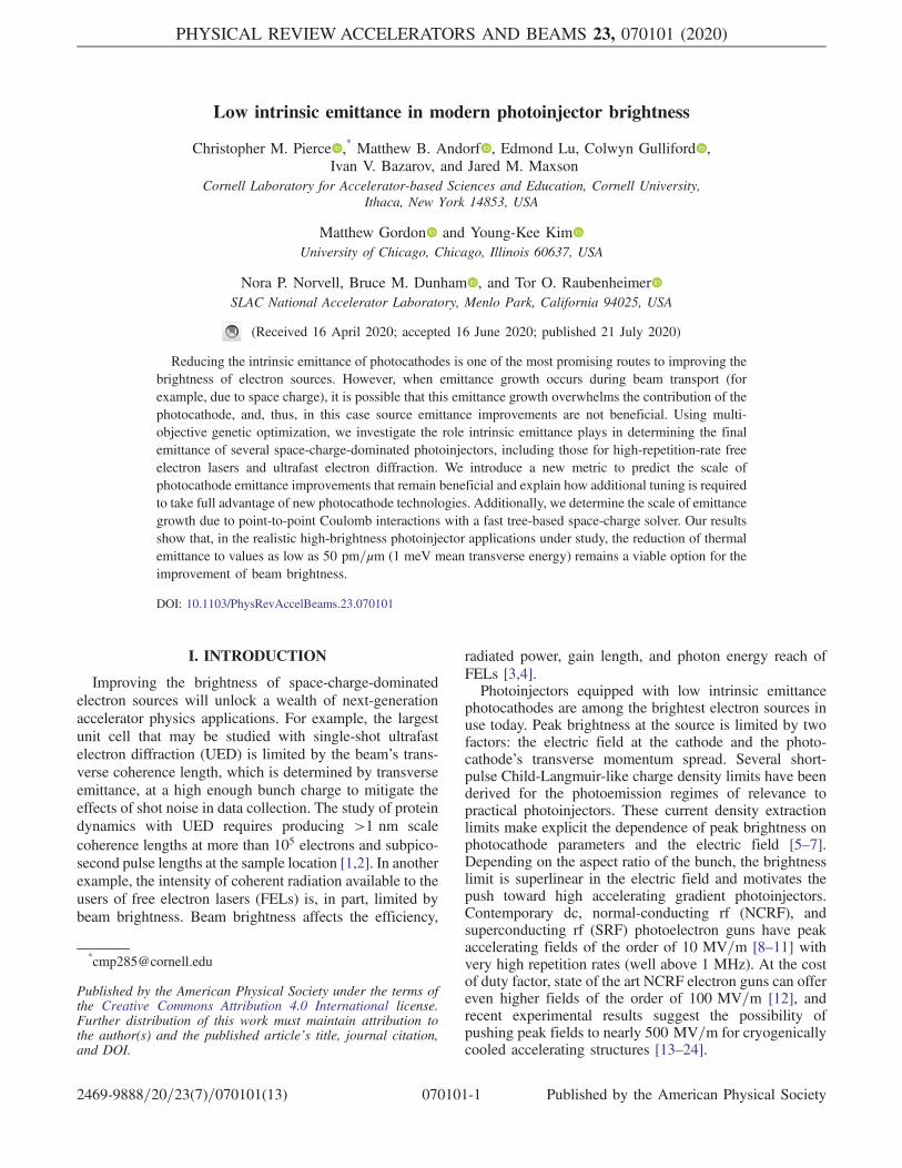
FIG. 1. An example of the initial longitudinal and transverse spatial distributions of the beam for each system. These examples wereselected from the 0 meV Pareto front and are the same individuals plotted in Fig. 5.
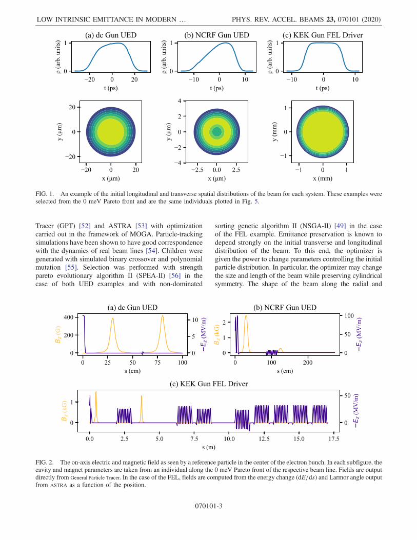
FIG. 2. The on-axis electric and magnetic field as seen by a reference particle in the center of the electron bunch. In each subfigure, thecavity and magnet parameters are taken from an individual along the 0 meV Pareto front of the respective beam line. Fields are outputdirectly from General Particle Tracer. In the case of the FEL, fields are computed from the energy change (dE=ds) and Larmor angle outputfrom ASTRA as a function of the position.
LOW INTRINSIC EMITTANCE IN MODERN … PHYS. REV. ACCEL. BEAMS 23, 070101 (2020)
070101-3
longitudinal axes is interpolated between the set of fourdistributions described in Ref. [38]. Example initial distri-butions taken from one individual for each beam line areshown in Fig. 1.The dc UED beam line is modeled after a similar
system under development at Cornell University usingthe cryogenically cooled photoemission source described inRef. [57]. The performance of this system under differentconditions than presently considered is discussed in
Ref. [58], where a detailed description of the layout andsimulation methodology is also provided. On-axis fields forthis beam line are shown in Fig. 2(a). The beam lineconsists of two solenoids that surround an NCRF single-cell bunching cavity and aid in transporting the high-brightness beam to the sample located at s ¼ 1 m. Theoptimizer is given control over all magnet and cavitysettings to minimize the rms emittance at the sample whilemaximizing bunch charge. Only solutions that keep thefinal spot size smaller than 100 μm rms and the final beamlength less than 1 ps rms are considered. These constraintswere chosen based on common sample sizes used indiffraction [25] and the timescale of lattice vibrationdynamics [59,60]. For a complete description of thedecisions, objectives, and constraints used for this system,refer to Table I.The high-gradient NCRF UED beam line is driven by a
1.6-cell 2.856 GHz gun capable of 100 MV=m and basedon a design currently in use at a number of labs [25,61–64].Samples are located at s ¼ 2.75 m, and the optimizer isgiven full control over two solenoids which surround anine-cell bunching cavity that is modeled after the first cellof the SLAC linac described in Ref. [65]. A discussion of
TABLE I. Optimizer configuration for the dc gun UED beamline.
Decision Range
Bunch charge 0–160 fCInitial rms beam size 0–1 mmInitial rms beam length 0–50 psMTE 0, 150 meVGun voltage 225 kVSolenoid current 1 and 2 0–4 ABuncher voltage 0–60 kVBuncher phase 90°
Objective Goal
rms emittance MinimizeDelivered bunch charge Maximize
Constraint Value
Final rms spot size <100 μmFinal rms bunch length <1 ps
TABLE II. Optimizer configuration for the NCRF UED beamline.
Decision Range
Bunch charge 0–300 fCInitial rms beam size 0–50 μmInitial rms beam length 0–50 psMTE 0, 150 meVGun phase −90°–90°Peak gun field 100 MV/mBeam energy 4.5 MeVSolenoid current 1 and 2 0–4 ABuncher peak power 0–25 MWBuncher phase 90°
Objective Goal
rms emittance MinimizeDelivered bunch charge Maximize
Constraint Value
Final rms spot size <100 μmFinal rms bunch length <1 ps
TABLE III. Optimizer configuration for the KEK gun FELdriver example.
Decision Range
Bunch charge 100 pCInitial rms beam size 0.05–10 mmInitial rms beam length 5–70 psMTE 0, 130 meVGun gradient 20–50 MV=mGun phase −60°–60°Gun energya 1.5–3.5 MeVSolenoid 1 field 0–0.4 TCapture cavity gradient 0–32 MV=mCapture cavity phase −180°–180°Capture cavity offset 0–2 mSolenoid 2 field 0–0.3 TSolenoid 2 offset 0–2 mCryomodule offset 0–3 mAccel. cavity 1, 2, and 4 field 0–32 MV=mAccel. cavity 1, 2, and 4 phase −90°–90°
Objective Goal
rms emittance MinimizeFinal rms bunch length Minimize
Constraint Value
Final energy >90 MeVEnergy spread <200 keVHigher-order energy spread <5 keV
aGun energy is computed from gradient and phase and notdirectly controlled by optimizer.
CHRISTOPHER M. PIERCE et al. PHYS. REV. ACCEL. BEAMS 23, 070101 (2020)
070101-4

our previous optimization experience with this beam lineunder a different set of constraints can be found inRef. [66]. As in the case of the dc UED beam line, theoptimizer was configured to minimize final rms emittancewhile maximizing delivered bunch charge under the con-straint of keeping the final spot size less than 100 μm rmsand the final length shorter than 1 ps rms. The decisions,objectives, and constraints of this optimization are detailedin Table II, and an example of the on-axis fields from anoptimized individual is shown in Fig. 2(b).Our FEL driver example includes a 1.5-cell 1.3 GHz
SRF gun in development at KEK for use in a CW energyrecovery linac (ERL) light source coupled with a
photoinjector lattice aimed at use in the linac coherentlight source II high energy upgrade (LCLS-II HE) [67].The gun energy is controlled by the optimizer but is in therange 1.5–3.5 MeV. Immediately after the gun is a 1.3 GHznine-cell capture cavity surrounded by two solenoids. Theremaining cavities, of the same design as the capture cavity,are shown in the plot of external fields in Fig. 2(c) andaccelerate the beam to its final energy of roughly 100 MeV.Accelerating cavity number three was kept off duringoptimization as a planned backup for cavity failure inthe real machine. The bunch charge was fixed to 100 pC,and optimizations were performed to minimize both rmsemittance and bunch length at the end of the injector
FIG. 3. The Pareto fronts of each beam line for the ∼150 and 0 meV MTE photocathodes and their characteristic MTE. The UEDexamples show between a factor of 10 and 100 improvement in brightness between the two Pareto fronts. The characteristic MTEcalculated from a simulation including the effects of Coulomb scattering is included for the dc and NCRF gun UED examples as ayellow cross.
LOW INTRINSIC EMITTANCE IN MODERN … PHYS. REV. ACCEL. BEAMS 23, 070101 (2020)
070101-5
system. Energy constraints were tailored for the injector’suse in the LCLS-II HE upgrade, and so we required validsolutions to have an energy greater than 90 MeV, an energyspread below 200 keV, and a higher-order energy spreadless than 5 keV. The full set of decisions, objectives, andconstraints is compiled in Table III.Initial generations of the genetic optimization were
evaluated with a small number of macroparticles to developa good approximation of the global optima before movingon to the more accurate simulations involving 105 macro-particles for the UED examples and 104 macroparticles forthe FEL driver. The optimization stopping condition wasthat improvement of the Pareto front with each successivegeneration fell below a threshold of approximately 10%relative change. The products of these optimizations areshown in Fig. 3.Both UED beam lines show a factor of between 10 and
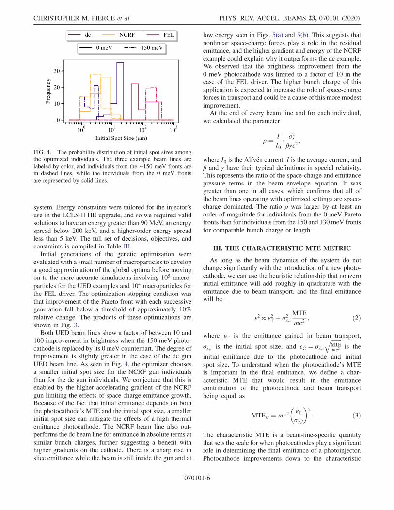
100 improvement in brightness when the 150 meV photo-cathode is replaced by its 0 meV counterpart. The degree ofimprovement is slightly greater in the case of the dc gunUED beam line. As seen in Fig. 4, the optimizer choosesa smaller initial spot size for the NCRF gun individualsthan for the dc gun individuals. We conjecture that this isenabled by the higher accelerating gradient of the NCRFgun limiting the effects of space-charge emittance growth.Because of the fact that initial emittance depends on boththe photocathode’s MTE and the initial spot size, a smallerinitial spot size can mitigate the effects of a high thermalemittance photocathode. The NCRF beam line also out-performs the dc beam line for emittance in absolute terms atsimilar bunch charges, further suggesting a benefit withhigher gradients on the cathode. There is a sharp rise inslice emittance while the beam is still inside the gun and at
low energy seen in Figs. 5(a) and 5(b). This suggests thatnonlinear space-charge forces play a role in the residualemittance, and the higher gradient and energy of the NCRFexample could explain why it outperforms the dc example.We observed that the brightness improvement from the0 meV photocathode was limited to a factor of 10 in thecase of the FEL driver. The higher bunch charge of thisapplication is expected to increase the role of space-chargeforces in transport and could be a cause of this more modestimprovement.At the end of every beam line and for each individual,
we calculated the parameter
ρ ¼ II0
·σ2xβγε2
;
where I0 is the Alfven current, I is the average current, andβ and γ have their typical definitions in special relativity.This represents the ratio of the space-charge and emittancepressure terms in the beam envelope equation. It wasgreater than one in all cases, which confirms that all ofthe beam lines operating with optimized settings are space-charge dominated. The ratio ρ was larger by at least anorder of magnitude for individuals from the 0 meV Paretofronts than for individuals from the 150 and 130 meV frontsfor comparable bunch charge or length.
III. THE CHARACTERISTIC MTE METRIC
As long as the beam dynamics of the system do notchange significantly with the introduction of a new photo-cathode, we can use the heuristic relationship that nonzeroinitial emittance will add roughly in quadrature with theemittance due to beam transport, and the final emittancewill be
ε2 ≈ ε2T þ σ2x;iMTEmc2
; ð2Þ
where εT is the emittance gained in beam transport,
σx;i is the initial spot size, and εC ¼ σx;iffiffiffiffiffiffiffiffiMTEmc2
qis the
initial emittance due to the photocathode and initialspot size. To understand when the photocathode’s MTEis important in the final emittance, we define a char-acteristic MTE that would result in the emittancecontribution of the photocathode and beam transportbeing equal as
MTEC ¼ mc2�εTσx;i
�2
: ð3Þ
The characteristic MTE is a beam-line-specific quantitythat sets the scale for when photocathodes play a significantrole in determining the final emittance of a photoinjector.Photocathode improvements down to the characteristic
FIG. 4. The probability distribution of initial spot sizes amongthe optimized individuals. The three example beam lines arelabeled by color, and individuals from the ∼150 meV fronts arein dashed lines, while the individuals from the 0 meV frontsare represented by solid lines.
CHRISTOPHER M. PIERCE et al. PHYS. REV. ACCEL. BEAMS 23, 070101 (2020)
070101-6

MTE are likely to translate into increased usablebrightness.The characteristic MTE of each example is shown in
Fig. 3. Photocathode improvements down to the level ofsingle-meV MTE do affect the final emittance of eachphotoinjector application studied here. The characteristicMTE of the NCRF UED and FEL driver examplesincreases to roughly 15 and 50 meV at high bunch chargeand short bunch length, respectively. The larger character-istic MTE of the NCRF UED example is likely due to thesmaller initial spot size of the individuals. This can be seenin Fig. 4. That smaller spot size will increase the character-istic MTE for the same emittance, because the initialemittance is less sensitive to photocathode parameters.Characteristic MTEs at short bunch lengths in the FEL
example are primarily limited by large emittance growth inbeam transport.To test the validity of the heuristic argument that initial
and transport emittance should add in quadrature, wesimulated each individual from the 0 meV Pareto frontswith a photocathode whose MTE is the characteristic MTE.The final emittance is expected to grow by a factor of
ffiffiffi2
p,
and we observe the ratio to be close to but slightly largerthan that value. The frequency of ratios for each beam lineis plotted in Fig. 6. For our investigation, we assume thatthe insertion of a new photocathode does not significantlychange beam transport. However, this condition will beviolated to some extent and could explain why the ratio
observed is slightly larger thanffiffiffi2
p.
FIG. 5. Emittance and beam sizes for an individual along the 0 meV Pareto front of each example. The UED individuals were selectedat 16 fC bunch charge. The projected emittance is the typical rms normalized transverse emittance, and the slice emittance is the averageof the emittance evaluated over 100 longitudinal slices. The beam width and length are also plotted for reference. The total projectedemittance in (a) is clipped at 500 pm for clarity.
LOW INTRINSIC EMITTANCE IN MODERN … PHYS. REV. ACCEL. BEAMS 23, 070101 (2020)
070101-7

IV. REOPTIMIZATION FOR NEWPHOTOCATHODES
Our optimization experience showed that taking fulladvantage of the initial emittance improvements affor-ded by a new low-MTE photocathode required the reop-timization of beam line parameters. In particular, whenindividuals from the 150 meV Pareto fronts of the UEDbeam lines are resimulated with a 0 meV photocathode andno changes to beam line parameters, their emittance is morethan 50% larger than the emittance of individuals in the0 meV Pareto front at comparable bunch charge. This canbe understood by considering the sensitivity of the transportemittance optimum to small changes in the initial spot size.The characteristic MTE analysis does not take into
account the fact that if shrinking the initial spot size fromits optimal value reduces the initial emittance more than itincreases emittance growth in transport, then the overallemittance will still go down. The initial emittance, as inEq. (1), can be reduced by using a smaller initial spot size.However, if the system was already at the initial spot sizewhich minimizes emittance growth in transport, as is thecase of individuals along the 0 meV Pareto front, thenchanging it will negatively affect beam line performance.Since the final emittance is roughly the quadrature sum ofthe initial emittance and the growth during transport, therewill be a trade-off in minimizing both the initial emittanceand emittance growth. If the system was previouslyoptimized with a high-MTE photocathode, then the optimalspot size will not be at the minimum transport emittancepossible, and new low-MTE photocathodes can unlockstrategies the optimizer avoided due to their larger spotsizes which increase initial emittance. In this case, reop-timization will be required upon the insertion of a newlow-MTE photocathode.This trade-off is represented graphically in Fig. 7 by
plotting emittance as a function of the initial spot size.
Initial emittance is linear in the initial spot size and isrepresented by a line whose slope depends on photocathodeMTE. Close to the optimum, the emittance due to transportmay be expressed as a polynomial expansion in σx;i which,to lowest order, is quadratic. The final emittance is roughlythe quadrature sum of both terms and has an optima at asmaller spot size than for transport emittance alone. Thecharacteristic MTE can also be represented in this plot,since the initial emittance for a photocathode with an MTEequal to the characteristic MTE will pass through the vertexof the transport emittance parabola.By using the second-order expansion of beam transport’s
contribution to the emittance (εT) as a function of initialspot size (σx;i) around the optimum,
εTðσx;iÞ ¼ Aðσx;i − σx;i;0Þ2 þ εT;0; ð4Þ
we can find the new optimal emittance with nonzero MTE.Here σx;i;0 is the optimal spot size, and εT;0 is the optimalemittance. To simplify our discussion, we consider the caseof optima that are highly sensitive to changes in the initialspot size. Define the unitless parameter x ¼ εT;0=ðAσ2x;i;0Þto measure the optimum’s sensitivity. In the limit ofsensitive optima (x ≪ 1), the new smallest emittance whenthe initial spot size is allowed to vary is
ε2opt ¼ ε2T;0 þ ε2C
�1 −
x2
MTEMTEC
�ðx ≪ 1Þ: ð5Þ
FIG. 6. Individuals from the 0 meV beam line were resimulatedwith a photocathode MTE equal to their characteristic MTE. Theprobability distribution of the ratio of the new final emittance tothe original final emittance is plotted.
FIG. 7. An illustration of how reoptimization may be requiredupon insertion of a new photocathode. In black is the emittancedue to transport (εT) as a function of the initial spot size. Aroundthe optimal spot size σx;i;0, this is approximately quadratic. Thesensitivity in this example is roughly x ≈ 0.001. The solid linesrepresent the initial emittance (εC) for three different thermalemittances. The dashed lines are the final emittance (εF) or thequadrature sums of initial and transport emittance. The optimalspot size with the 150 meV photocathode is significantly smallerthan with a 0 or even 1 meV photocathode.
CHRISTOPHER M. PIERCE et al. PHYS. REV. ACCEL. BEAMS 23, 070101 (2020)
070101-8

The new optimal initial spot size will be smaller for thenonzero MTE photocathode and, in the limit of small x, isapproximately
σ2x;i;opt ¼ σ2x;i;0
�1 − x
MTEMTEC
�ðx ≪ 1Þ: ð6Þ
In practice, we observe the tendency of the optimizer tochoose smaller initial spot sizes for beam lines withnonzero photocathode MTE. In Fig. 4, we plot thefrequency of initial spot sizes from the 0 and ∼150 meVPareto fronts of each beam line. For the UED examples, the
initial spot sizes for individuals in the 150 meV Pareto frontare universally smaller than for those in the 0 meV Paretofront. There is less of an impact on the FEL example, whichcould be due to the optima being highly sensitive tochanges in the initial spot size.Systems with insensitive optima (large x) will tolerate
higher MTE photocathodes than the original characteristicMTE metric implies. Likewise, systems where the emit-tance grows rapidly for small changes in σx;i (small x)cannot afford to decrease the initial spot size to compensatefor any increase in the photocathode MTE. The secondterm in the square brackets of Eq. (5) is the relative scale for
FIG. 8. The rms and core emittance of an individual with 105 electrons per bunch from the dc gun UED and NCRF gun UED 0 meVMTE Pareto fronts. In the row labeled “beam dynamics”, the yellow lines were computed with the point-to-point space-charge algorithmand the blue lines with smooth space charge. The solid lines are the rms normalized emittance, and the dashed lines are the coreemittance. Below are plots of the beam’s transverse phase space at the sample location computed with the smooth and point-to-pointmethods. Linear x − px correlation has been removed, and the ellipse of phase space second moments is plotted in addition to theparticle density.
LOW INTRINSIC EMITTANCE IN MODERN … PHYS. REV. ACCEL. BEAMS 23, 070101 (2020)
070101-9
how much changing the initial spot size can improveemittance and can provide a rough guide to experimen-talists for determining when a new photocathode technol-ogy requires reoptimization of the beam line. The MTE forwhich the transport and photocathode contributions to thefinal emittance are the same even when allowing the initialspot size to vary is
MTE0C ¼ MTEC
�1þ x
2
�ðx ≪ 1Þ: ð7Þ
Although analytical formulas for the optimal emittance andspot size which are accurate to all orders in xmay be found,they do not lend themselves to efficient analysis, andnumerical methods may be better suited for investigatingthe properties of systems with insensitive optima.For each system, we can use the Pareto fronts obtained
for the 0 and ∼150 meV MTE photocathodes to estimatethe sensitivity parameter x and calculate the correction tothe characteristic MTE. These Pareto fronts give us a valueof the optimal emittance from Eq. (5) for two differentvalues of εC, and from there we can solve for x. Thisoperation was performed on each system, and the sensi-tivity parameter was used to calculate the correctedcharacteristic MTE. The correction in all cases was atthe single percent level, indicating that our optima aresensitive to the initial spot size. Consequently, the uncor-rected characteristic MTE, for the three realistic photo-injectors studied here, does a good job at predicting thescale at which photocathode improvements no longerimprove brightness.
V. STOCHASTIC SPACE CHARGE
DIH is known to play a role in degrading the emittanceof cold and dense electron beams. When the distancebetween particles falls below the Debye length of the one-component plasma, interparticle collisions can becomeimportant and can affect the momentum distribution ofthe bunch in a stochastic manner. This effect will show upprominently when the average kinetic energy of particles inthe transverse direction is of the same scale as the potentialenergy due to the Coulomb repulsion of the particle’sneighbors. The result is that the nascent momentum spreadgrows above its initial value by an amount ΔkT½eV� ¼1.04 × 10⁻⁹ðn0½m−3�Þ1=3 [41,68]. Using the electron num-ber density (n0) at the beginning of each optimizedexample, the scale of DIH expected for all three beamlines is 1 meV. Beyond DIH, Coulomb scattering after thecathode can lead to continuous irreversible emittancegrowth, but these effects are difficult to estimate analyti-cally. We expect DIH to be important in our simulationswith the 0 meV MTE photocathode due to the cold densebeams inside the guns.To determine how much of an effect Coulomb scattering
has on final emittance in our systems, one example from
each of the dc and NCRF UED 0 meV Pareto fronts waschosen and simulated using a stochastic space-chargemodel. The new algorithm for efficiently computing theeffects of stochastic space charge is based off of the Barnes-Hut tree method and will be discussed in detail in aforthcoming publication by Gordon, Maxson, et al. Boththe NCRF and dc UED individuals had a bunch charge of10 fC. Simulations were performed with GPT’s smoothspace-charge model discussed in Ref. [69] and with thetree-code method. The rms projected and core emittance[70] along each beam line and with each space-chargemodel are shown in Fig. 8. Coulomb scattering contributesa factor of 2 increase in final emittance for both cases.
VI. CONCLUSION
We have shown that characteristic MTE can be a usefultool in understanding the scale of MTE at which photo-cathode improvements translate to an increase in usablebrightness. These beam lines, which are representative ofhigh-brightness photoinjector applications, have character-istic MTEs on the scale of single to tens of meV, well belowthe 150 meV MTE of today’s commonly used photo-cathodes. Improvements in photocathode technology downto the level of 1 meV and below stands to improve thebrightness of practical photoinjectors by an impressive 2orders of magnitude. However, it is not enough to simplyinsert a low-MTE photocathode into an electron gun toachieve low final emittance.To achieve this level of photoinjector performance,
advanced optimization techniques like MOGA will needto be integrated into the design and tuning of futureaccelerators. With the use of new photocathode technolo-gies, further optimization may be required to take fulladvantage of low MTE. The sensitivity of the optima tochanges in the initial spot size provides a guide for when itis necessary to reoptimize. In addition, when in the regimeof single-meV photocathodes, existing models of smoothspace charge break down, and the effects of Coulombscattering become important in determining ultimatebrightness. Although the results of the present work arenot affected by this problem because we are concerned onlywith order of magnitude changes in emittance, designtools for future accelerators may need to move to high-performance point-to-point space-charge models to obtaingood agreement with reality.With the continued improvement of photocathode-based
electron sources and, in particular, the reduction of MTE inphotocathode materials, bright beams will open up newpossibilities for accelerator physics applications. Notably,an increase in brightness would enable the time-resolvedcharacterization of biological macromolecules with UED[71] as well as benefit x-ray FELs with a correspondingincrease in total pulse energy benefiting a wide variety ofx-ray scattering experiments in fields ranging from con-densed matter physics, to chemistry, to biology [72]. Work
CHRISTOPHER M. PIERCE et al. PHYS. REV. ACCEL. BEAMS 23, 070101 (2020)
070101-10

is already underway in understanding and beating theeffects which limit photocathode MTE and in makingexisting low-MTE photocathodes more practical for accel-erator facility use [73–75]. Additionally, structured particleemitters have already been predicted to mitigate theemittance growth observed from disorder-induced heatingin the present simulations [76]. If these photocathodeimprovements can be realized, then their results couldprovide as much as 2 orders of magnitude improvement inthe final brightness of realistic modern photoinjectors.
ACKNOWLEDGMENTS
This work was supported by the U.S. National ScienceFoundation under Grant No. PHY-1549132, the Centerfor Bright Beams. We thank the U.S.–Japan Science andTechnology Cooperation Program in High Energy Physicsfor providing additional travel funding.
[1] B. J. Siwick, J. R. Dwyer, R. E. Jordan, and R. Miller,Femtosecond electron diffraction studies of strongly drivenstructural phase transitions, Chem. Phys. 299, 285 (2004).
[2] J. R. Dwyer, C. T. Hebeisen, R. Ernstorfer, M. Harb, V. B.Deyirmenjian, R. E. Jordan, and R. D. Miller, Femtosecondelectron diffraction: ‘making the molecu-lar movie’, Phil.Trans. R. Soc. A 364, 741 (2006).
[3] C. W. Roberson, Y. Y. Lau, and H. P. Freund, Emittance,brightness, free-electron laser beam quality, and thescaled thermal velocity, in High-Brightness Accelerators,Vol. 178, edited by A. K. Hyder, M. F. Rose, and A. H.Guenther (Springer, Boston, 1988), pp. 627–645.
[4] S. Di Mitri and S. Spampinati, Estimate of free electronlaser gain length in the presence of electron beam collectiveeffects, Phys. Rev. Accel. Beams 17, 110702 (2014).
[5] I. V. Bazarov, B. M. Dunham, and C. K. Sinclair, Maxi-mum Achievable Beam Brightness from Photoinjectors,Phys. Rev. Lett. 102, 104801 (2009).
[6] D. Filippetto, P. Musumeci, M. Zolotorev, and G.Stupakov, Maximum current density and beam brightnessachievable by laser-driven electron sources, Phys. Rev.Accel. Beams 17, 024201 (2014).
[7] G. Shamuilov, A. Mak, K. Pepitone, and V. Goryashko,Child-Langmuir law for photoinjectors, Appl. Phys. Lett.113, 204103 (2018).
[8] I. Pinayev et al., High-gradient High-charge CW Super-conducting RF gun with CsK2Sb photocathode, arXiv:1511.05595.
[9] B. M. Dunham, C. K. Sinclair, I. V. Bazarov, Y. Li, X. Liu,and K.W. Smolenski, Performance of a very high voltagephotoemission electron gun for a high brightness, highaverage current ERL injector, in Proceedings of the 16thIEEE International Pulsed Power Conference, Albuquer-que, NM (IEEE, Piscataway, NJ, 2007), pp. 1224–1226.
[10] D. H. Dowell, J. W. Lewellen, D. Nguyen, and R. Rimmer,The status of normal conducting RF (NCRF) guns, asummary of the ERL2005 workshop, Nucl. Instrum.Methods Phys. Res., Sect. A 557, 61 (2006).
[11] A. Arnold and J. Teichert, Overview on superconductingphotoinjectors, Phys. Rev. Accel. Beams 14, 024801(2011).
[12] M. Ferrario, J. E. Clendenin, D. T. Palmer, J. B. Rosenzweig,and L. Serafini, Homdyn study for the LCLS rf photo-injector, Technical Report No. SLAC-PUB 8400, INFN,Frascati, Italy, 2000.
[13] J. Rosenzweig, A. Cahill, B. Carlsten, G. Castorina, M.Croia, C. Emma, A. Fukusawa, B. Spataro, D. Alesini, V.Dolgashev, M. Ferrario, G. Lawler, R. Li, C. Limborg, J.Maxson, P. Musumeci, R. Pompili, S. Tantawi, and O.Williams, Ultra-high brightness electron beams from very-high field cryogenic radiofrequency photocathode sources,Nucl. Instrum. Methods Phys. Res., Sect. A 909, 224(2018).
[14] A. Cahill, J. Rosenzweig, V. Dolgashev, S. Tantawi, and S.Weathersby, High gradient experiments with X -bandcryogenic copper accelerating cavities, Phys. Rev. Accel.Beams 21, 102002 (2018).
[15] X. J. Wang, M. Babzien, K. Batchelor, I. Ben-Zvi, R. I.Malone, X. Pogorelski, X. Qui, J. Sheehan, J. Sharitka,and T. Srinivasan-Rao, Experimental characterization ofhigh-brightness electron photoinjector, in The Proceedingsof FEL95, New York (JACoW Publishing, Geneva,Switzerland, 1995).
[16] J. Rosenzweig, A. Cahill, V. Dolgashev, C. Emma, A.Fukasawa, R. Li, C. Limborg, J. Maxson, P. Musumeci, A.Nause, R. Pakter, R. Pompili, R. Roussel, B. Spataro, andS. Tantawi, Next generation high brightness electron beamsfrom ultrahigh field cryogenic rf photocathode sources,Phys. Rev. Accel. Beams 22, 023403 (2019).
[17] A. H. McEuen, P. Lui, E. Tanabe, and V. Vaguine, , High-power operation of accelerator structures at liquid nitrogentemperature, IEEE Trans. Nucl. Sci. 32, 2972 (1985).
[18] H. A. Schwettman, J. P. Turneaure, W.M. Fairbank, T. I.Smith, M. S. McAshan, P. B. Wilson, and E. E. Chambers, ,Low temperature aspects of a cryogenic accelerator, IEEETrans. Nucl. Sci. 14, 336 (1967).
[19] K. Nordlund and F. Djurabekova, Defect model for thedependence of breakdown rate on external electric fields,Phys. Rev. Accel. Beams 15, 071002 (2012).
[20] C. M. Fortgang, G. O. Bolme, J. Lamoureux, and D. J.Liska, Cryogenic experiments on rf accelerating structures,Nucl. Instrum. Methods Phys. Res., Sect. A 262, 197(1987).
[21] A. Descoeudres, T. Ramsvik, S. Calatroni, M. Taborelli,and W. Wuensch, DC breakdown conditioning and break-down rate of metals and metallic alloys under ultrahighvacuum, Phys. Rev. Accel. Beams 12, 032001 (2009).
[22] A. Grudiev, S. Calatroni, and W. Wuensch, New local fieldquantity describing the high gradient limit of acceleratingstructures, Phys. Rev. Accel. Beams 12, 102001 (2009).
[23] V. Dolgashev, S. Tantawi, Y. Higashi, and B. Spataro,Geometric dependence of radio-frequency breakdown innormal conducting accelerating structures, Appl. Phys.Lett. 97, 171501 (2010).
[24] R. A.Marsh, M. A. Shapiro, R. J. Temkin, V. A. Dolgashev,L. L. Laurent, J. R. Lewandowski, A. D. Yeremian, andS. G. Tantawi, X-band photonic bandgap accelerator
LOW INTRINSIC EMITTANCE IN MODERN … PHYS. REV. ACCEL. BEAMS 23, 070101 (2020)
070101-11
structure breakdown experiment, Phys. Rev. Accel. Beams14, 021301 (2011).
[25] S. P. Weathersby et al., Mega-electron-volt ultrafast elec-tron diffraction at SLAC National Accelerator Laboratory,Rev. Sci. Instrum. 86, 073702 (2015).
[26] J. Yang, K. Kan, N. Naruse, Y. Yoshida, K. Tanimura, andJ. Urakawa, 100-femtosecond MeV electron source forultrafast electron diffraction, Radiat. Phys. Chem. 78, 1106(2009).
[27] Y. Ding, A. Brachmann, F.-J. Decker, D. Dowell, P. Emma,J. Frisch, S. Gilevich, G. Hays, P. Hering, Z. Huang, R.Iverson, H. Loos, A. Miahnahri, H.-D. Nuhn, D. Ratner, J.Turner, J. Welch, W. White, and J. Wu, Measurements andSimulations of Ultralow Emittance and Ultrashort ElectronBeams in the Linac Coherent Light Source, Phys. Rev.Lett. 102, 254801 (2009).
[28] J. Maxson, D. Cesar, G. Calmasini, A. Ody, P. Musumeci,and D. Alesini, Direct Measurement of Sub-10 fs Rela-tivistic Electron Beams with Ultralow Emittance, Phys.Rev. Lett. 118, 154802 (2017).
[29] S. Pastuszka, D. Kratzmann, D. Schwalm, A. Wolf, andA. S. Terekhov, Transverse energy spread of photoelec-trons emitted from GaAs photocathodes with negativeelectron affinity, Appl. Phys. Lett. 71, 2967 (1997).
[30] L. Cultrera, S. Karkare, H. Lee, X. Liu, I. Bazarov, and B.Dunham, Cold electron beams from cryocooled, alkaliantimonide photocathodes, Phys. Rev. Accel. Beams 18,113401 (2015).
[31] P. Musumeci, J. G. Navarro, J. Rosenzweig, L. Cultrera,I. Bazarov, J. Maxson, S. Karkare, and H. Padmore,Advances in bright electron sources, Nucl. Instrum. Meth-ods Phys. Res., Sect. A 907, 209 (2018).
[32] S. Karkare, A. Gowri, W. Andreas Schroeder, J. KevinNangoi, A. Tomas, M. Jared, and P. Howard, UltracoldElectrons via Near-Threshold Photoemission from Single-Crystal Cu(100), arXiv:2002.11579.
[33] B. Carlsten, New Photoelectric Injector Design for theLos Alamos National Laboratory XUV FEL Accelerator,in Proceedings of FEL88, Jerusalem, Israel (JACoWPublishing, Geneva, Switzerland, 1988).
[34] K. Floettmann, Emittance compensation in split photo-injectors, Phys. Rev. Accel. Beams 20, 013401 (2017).
[35] X. Qiu, K. Batchelor, I. Ben-Zvi, and X.-J. Wang,Demonstration of Emittance Compensation through theMeasurement of the Slice Emittance of a 10-ps ElectronBunch, Phys. Rev. Lett. 76, 3723 (1996).
[36] L. Serafini and J. B. Rosenzweig, Envelope analysis ofintense relativistic quasi laminar beams in rf photoinjec-tors: A theory of emittance compensation, Phys. Rev. E 55,7565 (1997).
[37] B. Carlsten, Space-charge-induced emittance compensa-tion in high-brightness photoinjectors, Part. Accel. 17, 27(1995), https://cds.cern.ch/record/1108320/files/p27.pdf.
[38] I. V. Bazarov, A. Kim, M. N. Lakshmanan, and J. M.Maxson, Comparison of dc and superconducting rf photo-emission guns for high brightness high average currentbeam production, Phys. Rev. Accel. Beams 14, 072001(2011).
[39] O. A. Anderson, Internal dynamics and emittance growthin space-charge-dominated beams, Part. Accel. 21, 30(1987), https://cds.cern.ch/record/1108052/files/p197.pdf.
[40] S. G. Anderson and J. B. Rosenzweig, NonequilibriumTransverse motion and emittance growth in ultrarelativisticspace-charge dominated beams, Phys. Rev. Accel. Beams3, 094201 (2000).
[41] J. M. Maxson, I. V. Bazarov, W. Wan, H. A. Padmore, andC. E. Coleman-Smith, Fundamental photoemission bright-ness limit from disorder induced heating, New J. Phys. 15,103024 (2013).
[42] K. Baptiste, J. Corlett, T. M. Huang, S. Kwiatkowski, D.Li, J. Qiang, F. Sannibale, J. Staples, R. Wells, L. Yang, A.Zholents, and J. McKenzie, Status of the LBNL Normal-Conducting CW VHF Photo-Injector, in Proceedings ofthe 23rd Particle Accelerator Conference, Vancouver,Canada, 2009 (IEEE, Piscataway, NJ, 2009), p. 4.
[43] E. Panofski, A. Jankowiak, T. Kamps, G. Kourkafas,and S. Eisebitt, Multi-objective Optimization of an SRFPhotoinjector for ERL and UED Application, in Proceed-ings of IPAC2017, Copenhagen, Denmark (JACoW,Geneva, Switzerland, 2017), p. 4.
[44] Y. Ineichen, Massively parallel multi-objective optimiza-tion with application to particle accelerators, Ph.D. thesis,ETH Zurich, Switzerland, 2013.
[45] E. Panofski, A. Jankowiak, T. Kamps, and A. Neumann,Multi-objective optimization of an SRF photoinjectorwithbooster section for high brightness beam performance, inProceedings of the 9th International Particle AcceleratorConference, Vancouver, BC, Canada (JACOW Publishing,Geneva, Switzerland, 2018), p. 4.
[46] H. J. Qian, D. Filippetto, and F. Sannibale, S-band photo-injector investigations by multiobjective genetic optimizer,in Proceedings of IPAC2016, Busan, Korea (JACOWPublishing, Geneva, Switzerland, 2016).
[47] L. Emery, Global optimization of damping ring designsusing a multi-objective evolutionary algorithm, inProceedings of the 21st Particle Accelerator Conference,Knoxville, TN, 2005 (IEEE, Piscataway, NJ, 2005),pp. 2962–2964.
[48] C. F. Papadopoulos, J. N. Corlett, D. Filippetto, J. Qiang,F. Sannibale, J. W. Staples, M. Venturini, and M. S.Zolotorev, Multiobjective optimization for the advancedphotoinjector experiment (APEX), in Proceedings of the32nd Free Electron Laser Conference, Malmö, Sweden(Max-lab, Sweden, 2010), p. 4.
[49] K. Deb, A. Pratap, S. Agarwal, and T. Meyarivan, A fastand elitist multiobjective genetic algorithm: NSGA-II,IEEE Trans. Evol. Comput. 6, 182 (2002).
[50] G. Rudolph, Convergence of evolutionary algorithms ingeneral search spaces, in Proceedings of IEEEInternational Conference on Evolutionary Computation,Nagoya, Japan (IEEE, New York, 1996), pp. 50–54,https://doi.org/10.1109/ICEC.1996.542332.
[51] I. V. Bazarov and C. K. Sinclair, Multivariate optimizationof a high brightness dc gun photoinjector, Phys. Rev.Accel. Beams 8, 034202 (2005).
[52] S. van der Geer and M. de Loos, Applications of theGeneral Particle Tracer code, in Proceedings of the Particle
CHRISTOPHER M. PIERCE et al. PHYS. REV. ACCEL. BEAMS 23, 070101 (2020)
070101-12
Accelerator Conference, Vancouver, BC, Canada, 1997(IEEE, New York, 1997), Vol. 2, pp. 2577–2579.
[53] K. Floettmann, ASTRA: A Space Charge TrackingAlgorithm (2017), http://www.desy.de/~mpyflo/Astra_manual/Astra-Manual_V3.2.pdf.
[54] C. Gulliford, A. Bartnik, I. Bazarov, L. Cultrera, J.Dobbins, B. Dunham, F. Gonzalez, S. Karkare, H. Lee,H. Li, Y. Li, X. Liu, J. Maxson, C. Nguyen, K. Smolenski,and Z. Zhao, Demonstration of low emittance in theCornell energy recovery linac injector prototype, Phys.Rev. Accel. Beams 16, 073401 (2013).
[55] K. Deb, Multi-Objective Optimization Using EvolutionaryAlgorithms (Wiley, New York, 2001), Vol. 16.
[56] E. Zitzler, M. Laumanns, and L. Thiele, SPEA2: Improvingthe strength Pareto evolutionary algorithm, TechnicalReport No. TIK-Report 103, ETH Library, Zurich, 2001.
[57] H. Lee, X. Liu, L. Cultrera, B. Dunham, V. O. Kostroun,and I. V. Bazarov, A cryogenically cooled high voltage DCphotoemission electron source, Rev. Sci. Instrum. 89,083303 (2018).
[58] C. Gulliford, A. Bartnik, and I. Bazarov, Multiobjectiveoptimizations of a novel cryocooled dc gun based ultrafastelectron diffraction beamline, Phys. Rev. Accel. Beams 19,093402 (2016).
[59] M. Ligges, I. Rajkovic, P. Zhou, O. Posth, C. Hassel, G.Dumpich, and D. von der Linde, Observation Of ultrafastlattice heating using time resolved electron diffraction,Appl. Phys. Lett. 94, 101910 (2009).
[60] M. J. Stern, L. P. R. de Cotret, M. R. Otto, R. P. Chatelain,J.-P. Boisvert, M. Sutton, and B. J. Siwick, Mappingmomentum-dependent electron-phonon coupling and non-equilibrium phonon dynamics with ultrafast electron dif-fuse scattering, Phys. Rev. B 97, 165416 (2018).
[61] P. Musumeci, M. S. Gutierrez, J. T. Moody, and C. M.Scoby, Time resolved relativistic electron diffraction, inProceedings of the 23rd Particle Accelerator Conference,Vancouver, Canada, 2009 (IEEE, Piscataway, NJ, 2009),p. 3.
[62] P. Zhu, Y. Zhu, Y. Hidaka, L. Wu, J. Cao, H. Berger, J.Geck, R. Kraus, S. Pjerov, Y. Shen, R. I. Tobey, J. P. Hill,and X. J. Wang, Femtosecond time-resolved MeV electrondiffraction, New J. Phys. 17, 063004 (2015).
[63] P. Zhu, J. Cao, Y. Zhu, J. Geck, Y. Hidaka, S. Pjerov, T.Ritschel, H. Berger, Y. Shen, R. Tobey, J. P. Hill, and X. J.Wang, Dynamic separation of electron excitation andlattice heating during the photoinduced melting of theperiodic lattice distortion in 2H-TaSe2, Appl. Phys. Lett.103, 071914 (2013).
[64] D. Filippetto and H. Qian, Design of a high-flux instrumentfor ultrafast electron diffraction and microscopy, J. Phys. B49, 104003 (2016).
[65] R. B. Neal, The Stanford two mile accelerator, TechnicalReport No. SLAC-REPRINT-1968-001, Stanford LinearAccelerator Center, Menlo Park, CA, 1968.
[66] C. Gulliford, A. Bartnik, I. Bazarov, and J. Maxson,Multiobjective optimization design of an rf gun basedelectron diffraction beam line, Phys. Rev. Accel. Beams 20,033401 (2017).
[67] T. Konomi, Y. Honda, E. Kako, Y. Kobayashi, S.Michizono, T. Miyajima, H. Sakai, K. Umemori, and S.Yamaguchi, Development of High Intensity, High Bright-ness, CW SRF Gun with Bi-Alkali Photocathode, Dresden,Germany (JACoW, Geneva, Switzerland, 2019), p. 4.
[68] S. B. van der Geer, M. P. Reijnders, M. J. de Loos, E. J. D.Vredenbregt, P. H. A. Mutsaers, and O. J. Luiten, Simu-lated performance of an ultracold ion source, J. Appl. Phys.102, 094312 (2007).
[69] G. Poplau, U. van Rienen, M. de Loos, and B. van derGeer, Fast calculation of space charge in beam line trackingby multigrid techniques, in Scientific Computing in Elec-trical Engineering, Vol. 4, edited by H.-G. Bock, F. d.Hoog, A. Friedman, A. Gupta, W. Langford, H. Neunzert,W. R. Pulleyblank, T. Rusten, F. Santosa, A.-K. Tornberg,W. H. A. Schilders, E. J. W. ter Maten, and S. H. M. J.Houben (Springer, Berlin, 2004), pp. 329–336.
[70] I. V. Bazarov, Synchrotron radiation representation inphase space, Phys. Rev. Accel. Beams 15, 050703(2012).
[71] G. Sciaini and R. J. D. Miller, Femtosecond electrondiffraction: heralding the era of atomically resolved dy-namics, Rep. Prog. Phys. 74, 096101 (2011).
[72] P. Abbamonte, F. Abild-Pederse, P. Adams, M. Ahmed,and F. Albert, New science opportunities enabled byLCLS-II x-r lasers, Technical Report No. SLAC-R-1053,SLAC, Menlo Park, CA, 2015.
[73] S. Karkare and I. Bazarov, Effect of nano-scale surfaceroughness on transverse energy spread from GaAs photo-cathodes, Appl. Phys. Lett. 98, 094104 (2011).
[74] L. Jones, D. Juarez-Lopez, B. Militsyn, T. Noakes, and C.Welsch, Transverse energy distribution measurementsfor polycrystalline and (100) copper photocathodes withknown levels of surface roughness, in Proceedings ofthe 9th International Particle Accelerator Conference,IPAC2018, Vancouver, British Columbia, Canada (JA-COW Publishing, Geneva, Switzerland, 2018), https://doi.org/10.18429/jacow-ipac2018-thpmk062.
[75] J. Feng, J. Nasiatka, W. Wan, S. Karkare, J. Smedley, andH. A. Padmore, Thermal limit to the intrinsic remittancefrom metal photocathodes, Appl. Phys. Lett. 107, 134101(2015).
[76] D. Murphy, R. Scholten, and B. Sparkes, Increasing theBrightness of Cold Ion Beams by Suppressing Disorder-Induced Heating with Rydberg Blockade, Phys. Rev. Lett.115, 214802 (2015).
LOW INTRINSIC EMITTANCE IN MODERN … PHYS. REV. ACCEL. BEAMS 23, 070101 (2020)
070101-13