Embed Size (px)
Citation preview

FLOW INITIATION IN
SOFTWARE DEFINED NETWORKING
A THESIS SUBMITTED TO THE GRADUATE SCHOOL OF INFORMATICS INSTITUTE
OF THE MIDDLE EAST TECHNICAL UNIVERSITY
BY
AHMAD SOLTANI
IN PARTIAL FULFILLMENT OF THE REQUIREMENTS FOR THE DEGREE OF MASTERS OF SCIENCE
IN INFORMATION SYSTEMS
FEBRUARY 2014

ii
FLOW INITIATION IN SOFTWARE DEFINED NETWORKING
Submitted by Ahmad SOLTANI in partial fulfillment of the requirements for the
degree of Master of Science in Information Systems, Middle East Technical
University by,
Prof. Dr. Nazife Baykal
Director, Informatics Institute, METU
Prof. Dr. Yasemin Yardımcı Çetin
Head of Department, Information Systems, METU
Assoc. Prof. Dr. Cüneyt F. BAZLAMAÇCI
Supervisor, Electrical and Electronics Engineering, METU
Examining Committee Members:
Prof. Dr. Nazife Baykal
Informatics Institute, METU
Assoc. Prof. Dr. Cüneyt F. BAZLAMAÇCI
Supervisor, Electrical and Electronics Engineering, METU
Assoc. Prof. Dr. Altan Kocyigit
Information Systems, Informatics Institute, METU
Assist. Prof. Dr. Pekin Erhan Eren
Information Systems, Informatics Institute, METU
Prof. Dr. Semih Bilgen
Electrical and Electronics Engineering, METU

iii
I hereby declare that all information in this document has been obtained and
presented in accordance with academic rules and ethical conduct. I also declare
that as required by these rules and conduct, I have fully cited and referenced all
material and results that are not original to this work.
Name, Last name: Ahmad SOLTANI
--------------------------------

iv
ABSTRACT
FLOW INITIATION IN SOFTWARE DEFINED NETWORKING
Ahmad SOLTANI
M.Sc., Department of Information Systems, Graduate School of Informatics
Supervisor: Assoc. Prof. Dr. Cüneyt F. BAZLAMAÇCI
February 2014, 71 pages
With today’s technology requirements, computer networks and specifically the
Internet is being expected to provide mobile, distributed and constantly changing
services to its users. Forwarding middle boxes used in the industry nowadays are
configured to have their low-level switching operations (e.g. packet handling),
tightly coupled to their high-level control definitions and algorithms. This fact has
contributed in slowing down the innovation in computer networks. Software
Defined Networking has recently been introduced as an abstraction between
those low-level and high-level functionalities by introducing a standard protocol
to act as an interface, which divides control and data planes in middle-boxes.
There are a number of challenges related to SDN most of which are still treated
with conventional network or computer science techniques, however some
v
challenges unique to SDN paradigm such as flow initiation overhead and
controller handling in networks also exist. The present study includes a
comprehensive literature review of the current state-of-the-art techniques, which
tackles these challenges and proposes a hybrid mechanism to address the flow
initiation issue for minimizing the overhead and the delay. This proposal uses the
unified network map available on controllers to form a-priori knowledge for
switches for making better forwarding decisions during the flow initiation
process.
KEYWORDS: Software Defined Networking, Service Centric Networking, Flow
Initiation, Multiple Controller Handling

vi
ÖZ
YAZILIM TANIMLI AĞLARDA AKIŞ BAŞLATMA
Ahmad SOLTANI
M.Sc., Bilişim Sistemler, Enformatik Enstitüsü
Tez Danışmanı: Doç. Dr. Cüneyt F. BAZLAMAÇCI
Şubat 2014, 71 sayfa
Günümüz teknoloji gereksinimleri ile, bilgisayar ağlarının ve özellikle İnternetin
kullanıcılarına, mobil, dağıtılmış ve sürekli değişen hizmetler sunabilmesi
bekleniyor. Yönlendirme kutuları ve arayüzlerinde, düşük seviyeli işlemler yüksek-
seviyeli kontrol işlemleri ile yüksek derecede tümleşik olarak tasarlanmıştır. Bu da
bilgisayar ağları alanında yaşanan inovasyon hızını yavaşlatmıştır. Yazılım Tanimli
Ağlar (YTA) yakin zamanda kontrol ve veri düzlemleri arasında bölünme sağlayan
bir arayüz standardı olarak ve bu düşük düzeyli ve üst düzeyli işlevler arasında bir
soyutlama katmanı olarak ortaya konmuştur. Çoğu YTA sorunları hala eski ağ veya
bilgisayar bilimleri teknikleri ile çözülmektedir ancak akış başlatılması ve
denetleyici yönetimi gibi SDN’e özgü başka sorunlar da vardır. Bu çalışma, bu
zorlukları ele alan kapsamlı bir literatür taraması içerir ve akış başlatılması

vii
sorununu gidermek için de hibrit bir mekanizma önerir. Bu öneri akışın
başlatılması sürecinde anahtarlar için daha iyi yönlendirme kararları almayı
sağlayan apriori bilgi oluşturmak için de denetleyicilerde bulunan birleşik ağ
haritasını kullanır.
ANAHTAR KELIMELER: Yazılım Tanımlı Ağ, Hizmet Odaklı Ağ, Akış Başlatma, Çoklu
Denetleyici Yönetimi

viii
ACKNOWLEDGEMENTS
I would like to take this opportunity to express my deepest gratitude and
admiration to my supervising professor and thesis advisor, Cüneyt Fehmi
BAZLAMAÇCI for his guidance, advice and his encouragement and mentorship in
the times that I lost my hope in myself, but he never stopped supporting me. His
technical insight throughout the research made this work possible.
I also would like to thank valuable assistance of Prof. Dr. Nazife BAYKAL and
Informatics Institute of METU.
Without the opportunities, laboratories and constantly available facilities of the
Electrical and Electronics Engineering Department of METU this study would not
be possible. I would like to take this chance to thank all of the members, research
assistants and staffs of EEE Department who helped me in my research. Their
efforts and support are much appreciated.

ix
… To My Professor
and Mentor

x
TABLE OF CONTENTS
ABSTRACT............................................................................................................................. iv
ÖZ ......................................................................................................................................... vi
ACKNOWLEDGEMENTS ...................................................................................................... viii
TABLE OF CONTENTS ............................................................................................................x
LIST OF TABLES .................................................................................................................... xii
LIST OF FIGURES ................................................................................................................. xiii
LIST OF SYMBOLS AND/OR ABBREVIATIONS ..................................................................... xiv
1 CHAPTER ONE .......................................................................................................... 1
1.1 Introduction to the problem ............................................................................ 1
1.2 Purpose of the study ...................................................................................... 15
1.3 Significance of the Study ................................................................................ 15
2 CHAPTER TWO ....................................................................................................... 17
2.1 Introduction ................................................................................................... 17
2.2 Flow initiation in OpenFlow ........................................................................... 21
2.3 Controller Handling ........................................................................................ 25
3 CHAPTER THREE ..................................................................................................... 28
3.1 Introduction ................................................................................................... 28
3.2 Flow initiation ................................................................................................ 28
4 CHAPTER FOUR ...................................................................................................... 38
4.1 Algorithm expression ..................................................................................... 38
4.2 Simulation ...................................................................................................... 40
4.3 DISCUSSION.................................................................................................... 64
5 CHAPTER FIVE ........................................................................................................ 66

xi
5.1 CONCLUSION .................................................................................................. 66
5.2 FUTURE WORKS ............................................................................................. 67
REFERENCES ....................................................................................................................... 69

xii
LIST OF TABLES
Table 1: List of Abbreviations ................................................................................. xiv
Table 2: Scenario specific flow initiation time reference ....................................... 38

xiii
LIST OF FIGURES
Figure 1: Requirements and basis for contemporary technologies ......................... 2
Figure 2: Software Defined Network Architecture .................................................. 6
Figure 3: Load balancer management overhead. .................................................... 9
Figure 4: Serval architecture overview [1] ............................................................. 12
Figure 5: Serval packet headers. [1] ....................................................................... 13
Figure 6: Detailed architecture of SAL. [1] ............................................................. 14
Figure 7: OpenFlow controller benchmarks. [20] .................................................. 20
Figure 8: Packet_in Echo in Flow initiation ............................................................ 23
Figure 9: Algorithm 1, Case 1: Optimal .................................................................. 30
Figure 10: Algorithm 1, case 2 : non-optimal ......................................................... 31
Figure 11: Algorithm 2, case 1: optimal ................................................................. 32
Figure 12: Algorithm 2, case 2: non-optimal .......................................................... 33
Figure 13: Hybrid Algorithm 3,Both cases : optimal .............................................. 34

xiv
LIST OF SYMBOLS AND/OR ABBREVIATIONS
Table 1: List of Abbreviations
Symbol Abbreviation Description
CCN Content Centric Network
CLI Command Line Interface
DNS Domain Name Server
GUI Graphical User Interface
HYB Hybrid Flow Initiation
ICN Information Centric Network
IP Internet Protocol
OFM Original Flow Message
OVSK Open Virtual Switch Kernel
PIM Packet In Message
RCP Routing Control Protocol
SCN Service Centric Network
SDN Software Defined Network
TCP Transport Control Protocol
UDP User Datagram Protocol
WAN Wide Area Network

1
1 CHAPTER ONE
INTRODUCTION
1.1 Introduction to the problem
Computer networks, as a type of communication infrastructure, are one of the
most important technical aspects of how we implement and use different types
of computerized information systems and distributed computing along with many
other technologies. In our survey conducted in order to find out fundamental
requirements of contemporary technologies, it became evident that many
technologies such as cloud computing, pervasive and embedded computing and
mobile computing, etc. need a basis of collaborative, distributed and specialized
processing of data. Meaning that the processing of data in order to provide
information is required to be distributed to ensure reliability and accessibility, be
in collaboration to provide context awareness and knowledge discovery, be
specialized so that each individual acquiring and processing data can perform its
optimal task instead of using a general purpose centralized computer. A
combination of ‘hardware and software technologies’, ‘algorithms’, and
‘frameworks and standards’ all based on the above mentioned basis provide
opportunities for secure, pervasive and powerful computation to address
fundamental requirements of contemporary technologies.

2
Figure 1: Requirements and basis for contemporary technologies
Computer networks were initially designed for serving fixed hosts with topology
dependent addresses, which drastically differs from what they are used for
nowadays (Nordstrom, Rexford, & Freedman, 2012). The internet as the largest
network of networks is being used for accessing services that run anywhere from
mobile phones and huge servers to a collection of dynamically changing
heterogeneous and/or virtual machines. Demands of technologies such as cloud
computing, mobile and embedded-distributed computing, etc. enforce a drastic
change in computer networks as the main enabler of today’s state-of-the-art

3
technologies. This is mainly the reason why many coping mechanisms such as
load balancers, DNS servers, etc. are developed to bridge the gaps between the
initial design of the computer networks and its contemporary use (Rexford,
2012).
On the other hand network middle boxes, which are responsible for main
operations in networks, namely packet forwarding, are proprietary and closed
sourced and the rate of innovation is almost completely dependent on the
producer company thus new architectural changes take a lot of time to be
materialized as fundamental solutions for networking challenges.
Contrary to computer software and operating systems, computer networking
architecture and the underlying principles of how they operate did not
experience a serious evolution during the last four decades. New paradigms have
started to emerge in late 90’s to cope with shifts in telecommunication network
consumer and developer demands (McKinney, Montgomery, Ouibrahim, Sijben,
& Stanaway, 1998) but computer networks in particular have started to play their
part in this evolution in 2005 (Feamster, Balakrishnan, & Rexford, 2004).
Principles of Software Defined Networking and new paradigms such as Service
Centric Networking (SCN) are promising in tackling these issues.
Some of these new methods, such as Routing Control Protocol (RCP) and “Serval”
project (Nordstrom, Rexford, & Freedman, 2012), have been proposed as new
architectures and concepts, to tackle networking challenges. Some, such as SDN,
have been proposed as standards and frameworks to enable such innovations
and to provide pace and power to research in computer networks.
1.1.1 Software Defined Networking
One of the major bottlenecks in computer networks research is that the network
programmers are bound with the capabilities that are provided by middle box

4
producers. Other than research and innovation blockage, computer network
middle boxes control the data flow in network in a completely decentralized
manner. This, along with pros, introduces some drawbacks for example creates a
lot of maintenance issues for operators and service providers. Middle boxes are
configured manually thus controlling the network becomes more error prone
(Brandon, 2013). Operators and administrators try every method to keep their
network integrated: via network manager applications, etc. (Kim & Feamster,
2013).
One reason why computer networks have not changed as much as other
computer technologies in their principles and methods may be that switches are
not as widely configured and administered by everyone as computers and
software are. Switches are mainly customized and configured in larger networks
by specialists and until a decade ago current network architecture and methods
were sufficient for most of their operations. Thus demand has been weak to stir a
revolution in the proprietary model of business in network solution companies.
Providing a proprietary middle box with a Command Line Interface (CLI) or other
types of GUI’s as its operating systems interface (e.g. cisco ios) has made it quite
hard for network policy makers and protocol designers to innovate.
Another reason is particularly due to lack of an abstraction between simple
switch fabric operations (data plane) and high level functions (control plane) that
operators employ to instruct routers to perform consistent to their policies. The
absence of decoupled data and control planes makes it difficult to change or
introduce new functionalities in switches without knowing and/or changing the
underlying data flow mechanisms. Software Defined Networking (SDN)
overcomes these limitations. Introducing a standard abstraction of low level
switch fabric operations, it proposes that the control plane should be decoupled

5
from the switch to provide flexible and scalable manipulation of control plane
without changing or even knowing the data flow mechanism of the switch fabric.
Emergence of “Software Defined Networking” as an evolution of concepts
introduced in 2005 brought a serious opportunity of a practical and drastic
change in computer networks for researchers, developers and even proprietary
middlebox producers by separating the decision and policy making functionality
of middleboxes from their packet forwarding features. For this it may be possible
to drive an analogy with the emergence of computer operating system in 1950’s
for UNIVAC and IBM. In computer systems CPU’s have low level functionalities
such as adding, reading and writing of bit level data and with the introduction of
operating systems an abstraction between these low level operations and high-
level applications was introduced. Similarly routers and generally switch fabric of
middleboxes have low-level operations of dropping, forwarding or de-
multiplexing of incoming packets. SDN in a similar way has introduced a
hardware abstraction of the system for computer networks.
Dependent control-data planes imply that they can hardly be developed
independently and freely. Since data and control planes are tightly coupled a
change in control-plane functionality implies a change in the forwarding
mechanism. A local abstraction between data and control planes is hard to
standardize due to different implementations by different vendors. There also is
an innate market resistance by vendors due to marginal profits of proprietary
operating systems from certificates and licenses as well as professional training
programs, etc.

6
Figure 2: Software Defined Network Architecture schema. Communication between switches and the controller is maintained by a controller protocol and applications are developed upon network operating system. (image regenerated based on the present study, literature review
and authors perception of SDN and its underlying components)
SDN principles imply that the control functionalities of several switches can be
moved to a remote server, commonly known as the “controller server” and can
be presented to the switch fabric by means of standardized protocols and
virtualization technologies remotely. Software Defined Networking introduces
several advantages such as fine-grained manipulation power over control
functions of routers in a network, faster and cheaper processes in the design of

7
new architectures and protocols as well as in testing their implications. However
these advantages also introduce new challenges.
These challenges broadly include providing a secure, reliable, accessible and
dynamic framework in which switches can interact with remote control planes or
namely “Controllers”. Specifically, challenges such as data flow initiation,
scalability issues of large networks, controller discovery, switch-controller
communication security, etc. are some existing challenges.
1.1.2 Service Centric Networking
One of the major changes came through rethinking the address scheme in
networks. Today’s networks operate based on an address scheme (IP addresses),
which is defined by the location of each node throughout the topology. This
address is then used to identify interfaces and sockets as well as to de-multiplex
packets (Nordstrom, Rexford, & Freedman, 2012). This scheme initially was
thought out to provide nodes with a communication channel rather than services
and contents. IP addresses, along with TCP/UDP port numbers and protocols
form a five-tuple identifier, which identifies a connection or a flow of data
between two nodes in today’s networks, which clearly makes the connection
completely dependent on the location of the serving and receiving nodes and
that is basically why it is hard to change the location of either end points
(Rexford, 2012) and why it is hard to define more than one flow of data within a
connection. This means when a server or client is dislocated or relocated, as in
case of a virtual machine migration for instance, the whole connection has to
start all over again. This fact creates a lot of inconveniences for needs of
operators and users of networks nowadays. Many servers in data centers are
being run on virtual machines and hosts on cloud, which change their location in
network topology and also geographically. Many users use hand-held devices to

8
receive a particular service and constantly switch between devices to access
different aspects of a service (e.g. accessing streaming media on mobile).
A lot of techniques were created to give the illusion of an integrated and constant
connection in case of server relocation and failure and/or client on the move and
clients agnostic to the location of computers providing the service they use cases.
These techniques are most of the time unreliable and need a lot of hardware and
management investment to function properly.
In a simple distributed or replicated service over the internet, as shown below,
whenever an instance of a service fails or migrates and whenever another
instance is sprung up, load balancer, wide area address resolution system and
and domain name service needs to be updated. This issue in turn produces
management challenges as in most types of distributed systems.
9
Figure 3: Load balancer management overhead. Upon failure of a distributed/replicated service instance, load balancer and WAN address resolution directories must be updated. (Image
regenerated from source: Jen Rexford’s speech on Software defined service-centric network (Rexford, 2012))
Likewise, in case of virtual machine migration since the serving machine needs to
maintain its IP address, it is either restricted to operate in a single layer-two
subnet, or to use triangular routing techniques to redirect packets to a service
that has been relocated.
Many other examples of such scenarios conclude that when a server is
dislocated, which is the case with many mobile and virtual machines in networks,
the connections and subsequently services to users have to be re-established.
In order to better support dynamic services for mobile and multi-homed devices
a better abstraction between service resolution policy and service resolution
mechanism is needed alongside abstractions that will allow service name

10
definition to be independent of IP addresses and port number. These in turn
allow a better separation of control and data planes in a very similar way to
software defined networking.
Few recent attempts to change network addressing schemes have introduced
information or context as the primary entity in networks instead of servers and
clients involving in a connection. Researchers in this field focus on the content
that is being exchanged rather than the parties exchanging it. Naming contents
and building routing protocols based on them will provide a better solution for
content replication, content movement and load balancing as well as location
awareness. “Information Centric Networking” or simply ICN is a concept also
known as Content Oriented Networking, which has sprung several projects
around the world such as CBCB (Carzaniga, Wolf, & Rutherford, 2004), DONA
(Koponen, Chawla, & Chun, 2007) and PERSUIT (Lagutin, Visala, & Tarkoma, 2010)
and MDHT (D’Ambrosio & et., 2011). Roots of ICN or Content Oriented
Networking lies in a study back in year 2000 when Cheriton introduced the
concept of Name-based routing in a project called TRIAD (Cheriton & Gritter,
2000).
A conceptually close but more inclusive approach was Service Centric Networking
(SCN), which first emerged in telecommunication networks in 1998, where
different parties such as Brokers and Retailers of services were introduced to
create an abstraction where access networks were no longer defining and
providing the service but instead they provided only the connectivity to service
providers. This framework was introduced by Bell Labs using an architecture
called TINA (McKinney, Montgomery, Ouibrahim, Sijben, & Stanaway, 1998).
One reason why the author in this study has chosen service centric networking as
a more inclusive approach to investigate is the convenience of conceiving all sorts
of content and information dissemination as a type of service instead of treating
11
all types of service as a type of content. (e.g. from a high-level user point of view
mere controlling of a remote surveillance camera might not explicitly convey an
information or content exchange). On the other hand Content Centric
Networking (CCN) studies like DONA and TRIAD do not tackle challenges such as
end-host stacks, server migration and host network integration (Freedman, et al.,
2010).
1.1.3 Serval
One of the most recent studies in the field of Service Centric Networking is a
project called “Project Serval” investigated by Mike Freedman and Jen Rexford
along with many other Ph.D. and Post-Doc contributors in the Princeton
University. In a single framework Serval aims to provide an architecture in which
services are identified by a service name and also flows that take those services
on network are identified by different identifiers called “flow identifier”. These
identifiers are completely independent of IP addresses, i.e., the service is free of
the locations where end points are located. In serval, the authors are also
defining a new layer in networking stack above the unchanged “Networking
Layer” called Service Access Layer (SAL). Without this layer Serval’s attempt
would be merely replacing IP with a new identifier which will not help with the
vision of service centric networking. Here ‘service’ is a process or a group of
processes offering the same functionality and a ‘flow’ is the traffic in the network
carrying the service. A flow needs to be dynamic in order to change its
parameters during a single service connection.

12
Figure 4: Serval architecture overview: regenerated from source: Serval (Nordstrom, Rexford, & Freedman, 2012)
In Serval, project investigators believe that the problem with the current
networking architecture, which makes it hard to define more than one flow for a
service and hard to recover a service instance failure, is not the IP addressing
scheme. Instead they believe that the network stack has to be changed. Today all
the identifiers in network, including the application and transport layers are IP
bound meaning that they run by identifiers based on IP addresses and port
numbers. By introducing SAL, which operates above an unmodified Network layer
(based on IP), authors of Serval propose identifying services and flows based on
their identifiers in SAL layer. As a result applications and processes can bind to
serviceID’s and flowID’s using the notion of Active Sockets instead of binding to a
five-tuple identifier of IP addresses and port numbers alongside protocols. A
serviceID is unique and its is flexible in representing different granularities of
service, i.e., it can correspond to a specific instance of a service or a group of
processes and even a distributed system which provides the same service. This
architecture enables late-binding as well as service level routing throughout the
network, which in turn may enable load balancing between different instances of
a service. It means that it is left to the underlying network stack to discover
13
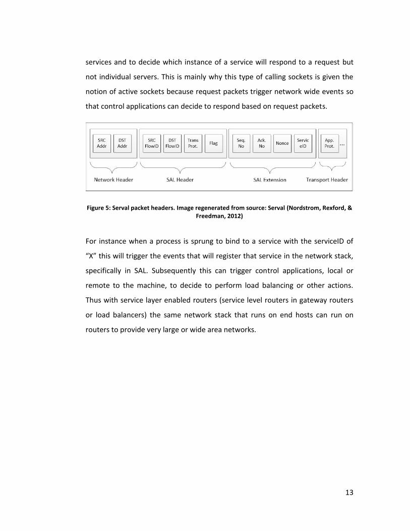
services and to decide which instance of a service will respond to a request but
not individual servers. This is mainly why this type of calling sockets is given the
notion of active sockets because request packets trigger network wide events so
that control applications can decide to respond based on request packets.
Figure 5: Serval packet headers. Image regenerated from source: Serval (Nordstrom, Rexford, & Freedman, 2012)
For instance when a process is sprung to bind to a service with the serviceID of
“X” this will trigger the events that will register that service in the network stack,
specifically in SAL. Subsequently this can trigger control applications, local or
remote to the machine, to decide to perform load balancing or other actions.
Thus with service layer enabled routers (service level routers in gateway routers
or load balancers) the same network stack that runs on end hosts can run on
routers to provide very large or wide area networks.

14
Figure 6: Detailed architecture of SAL. Image regenerated from source: Serval (Nordstrom, Rexford, & Freedman, 2012)
Using a controller API on an SDN based controller a variety of service discovery,
failover and load balancing policies can be introduced to end hosts and middle-
boxes. Thus the controller now can interact with not only end hosts running
processes based on serviceIDs but also SDN enabled switches that perform
service oriented forwarding in the network.
Some challenges that are being studied in Serval as an architecture based on SDN
are joining the end-host and switch control functionalities, software defined
service resolution and path selection, as well as general challenges such as
communication security and policies to register serviceIDs and multiple dynamic
service instance handling methods.
15
1.2 Purpose of the study
In Software Defined Networking the time it takes and the process necessary for a
switch to obtain forwarding rules for new packet types is called “flow initiation
overhead”. This overhead increases the time needed for the first packet of a flow
to reach its destination.
This study enhances current solutions related to flow initiation in Software
Defined Networking by proposing a hybrid algorithm, which uses currently
available technology and methods to optimize the time needed for flow initiation.
As an innate consequence, a tradeoff in the form of extra traffic is introduced by
the proposed algorithm. However, a through literature review suggests that
Service Centric Networking bears fundamental solutions to minimize the risks of
this tradeoff.
This study proposes the utilization of Service Centric methods and Serval project
in particular to deal with the tradeoffs resulting from the proposed flow initiation
algorithm.
1.3 Significance of the Study
Although the flow initiation overhead, as a scalability challenge, does not pose a
threat in near future, thanks to high capacity of controllers to handle thousands
of requests with low latency (Yeganeh, Tootoonchian, & Ganjali, 2013), it is worth
mentioning that computer networks and internet grow continuously and new
paradigms emerge that utilize the network in a more intensive manner.
Considering high traffic networks with wide topologies (e.g. operators and
datacenters), scalability of Software Defined Networking is introduced as one of
the most important challenges of its architecture. Enhancing flow initiation time
leverages scalability of Software Defined Networks while optimizing resource
usage in SDNs.

16
In order to tackle bottleneck issues of SDN, which is common in centralized
controller systems, a variety of solutions have been proposed (ONF O. , 2011). As
a result of our literature review we have concluded that alternatively the Service
Centric Networking mechanisms introduced in Serval Project can also resolve
these and related issues.
Service Centric approaches have already been employed and tested for different
services such as HTTP and FTP however the present study argues that
implementation of controller service using SCN principles with Serval architecture
is an alternative solution for handling multiple controllers in SDNs.
17
2 CHAPTER TWO
THEORY
2.1 Introduction
Among all the challenges there yet to be tackled, the present study takes SDN
flow initiation challenge in hand and provides solutions to this problem. The
author will conduct a series of implementations and tests to demonstrate how
SCN resolves implementation obstacles and challenges for SDN and vice versa.
SCN needs an implementation platform in which a new addressing scheme can be
defined and processed so the traffic can be forwarded based on serviceIDs as well
as introducing new layers into the network stack. SDN is a promising architecture,
which can house these types of innovations. Otherwise current technology only
allows enhancements over the conventional addressing scheme.
On the other hand SDN has some innate challenges such as scalability and
controller handling, and SCN is a very promising architecture to provide better
scalability, load balancing and service discovery opportunities without the need
for error prone third party patches to the server-client structure.
This co-existence and co-operation plays an important role in facilitating the
solution for number of challenges for both sides as well as providing a platform
on which many requirements of contemporary networking are met. In the
literature review process of the present study, it became evident that a service
centric and software defined networking platform will provide a lot of

18
fundamental solution opportunities for future networks such as cloud computing
and the need for distributed and collaborative computing. Without an abstraction
between service policy making and service forwarding functionalities it is hard to
imagine fast innovations in new methods to provide technological requirements
of contemporary computing needs. In turn, without a separation between data
and control planes of switches, a radical change in network architecture to house
new methods seems hard to maintain.
One of the most successful implementations of SDN is the OpenFlow standard
protocol, which allows experimental studies to be tested and implemented on
networks as well. An OpenFlow compliant switch or router still includes low level
fast packet forwarding capabilities and tables locally, but high-level routing
protocols are applied on the switch using a remote server on the network. Unlike
earlier attempts to realize data and control plane separation, such as Ethane
(Nick McKeown, 2007), Open flow does not require customization of hardware
(switches that support Ethane protocol). Furthermore, earlier implementations
such as RCP (Feamster, Balakrishnan, & Rexford, 2004) although made
deployment easier, were limited to what hijacked protocols (BGP, RIP, etc) could
support and could not have further innovation or introduction of new protocols,
and FORCES (Yang & Anderson, 2004) required standardization, adoption and
deployment of new hardware. OpenFlow uses a secure protocol to allow high
level control functions to interact with switches via installing rules into tables in
switches; these tables are named flow tables. When a switch receives a packet, it
compares it with the available rules and applies the set of mandated actions
accordingly (e.g. forwards the packet to a port, or drops it or delays it). In case
there are no rules associated with the corresponding pattern, the switch queues
the packet in its memory and asks the controller for a set of actions for the new
packet. Controller, on the other hand, which is listening (as default on port 6633)
receives the packet and de-multiplexes it to the upper stacks locally, where it is

19
received by the listening instance of a controller application, which is also
referred to as Network Operating System.
There are quite a variety of network operating systems available in different
programming languages such as the following:
- NOX: A C++/Python controller built and open sourced by Nicira Networks
(Nicira).
- POX: A Python based controller application, which is mainly suggested for
research purposes (Nicira).
- Beacon: A Java controller built by David Erickson at Stanford (Beacon).
- Maestro: A Java controller built by Zheng Cai at Rice university (Maestro).
Each controller application has its own development team, which provides
similar features but have their own unique libraries too. Beacon controller
developers claim that it is stable and has had no down-time since it has
started to control a network of 100 virtual and 20 physical switches for
months. It is cross-platform, open-source, fast and dynamic. Beacon is written
and based on Java programming language (Beacon).
NOX is the original OpenFlow controller which is based on C++ and provides
ease of development on Linux.
POX is NOX’s younger sibling which is purely based on Python programming
language and is suitable for research and fast deployment projects.
Maestro is funded by NSF and is being developed in Rice University.
Following is a benchmark of different OpenFlow controllers (network operating
systems). Although this figure is only provided for historical purposes, it clearly
demonstrates the number of flows per second handled by different controllers
running on a number of CPU threads.
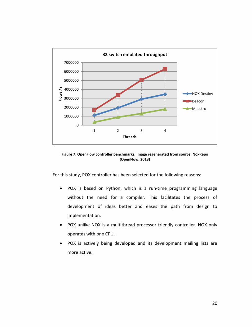
20
Figure 7: OpenFlow controller benchmarks. Image regenerated from source: NoxRepo (OpenFlow, 2013)
For this study, POX controller has been selected for the following reasons:
POX is based on Python, which is a run-time programming language
without the need for a compiler. This facilitates the process of
development of ideas better and eases the path from design to
implementation.
POX unlike NOX is a multithread processor friendly controller. NOX only
operates with one CPU.
POX is actively being developed and its development mailing lists are
more active.
0
1000000
2000000
3000000
4000000
5000000
6000000
7000000
1 2 3 4
Flo
ws
/ s
Threads
32 switch emulated throughput
NOX Destiny
Beacon
Maestro
21
2.2 Flow initiation in OpenFlow
OpenFlow as a control-switch communication protocol provides three types of
messages transmitted between switches and the controller. The author will not
discuss all message types here since this exceeds the boundaries of this research.
A specific message however, namely “Packet_in”, will be discussed which is
signaled when switch forwards a part or whole bits of a packet to controller for
routing decisions to be made accordingly. Packet_in message is a type of
asynchronous message. Asynchronous messages are sent by switches mainly to
report a state, error or arrival of a new type of packet.
When a switch receives a packet, which does not have a rule or set of actions
associated with it in its forwarding table, and the switch has enough buffer
memory, Packet_in event contains only some fraction of the original packet
header and a bufferID to be used by the controller when setting the forwarding
rule for the corresponding new packet (ONF O. N., OpenFlow Switch
Specification, Version 1.0 (Wire Protocol 0x04), 2011). Consequently when the
controller decides what to apply on the newly arriving packets, using OpenFlow
standard with TLS (Transport Layer Security) or TCP communication protocol,
inserts a rule in the forwarding table of the corresponding switch. Afterwards
switch acts on the buffered packet(s) based on this new rule.
In case a switch does not support packet buffering or has run out of buffer
memory, it forwards the whole packet instead and will act based on the new rule
once it is dictated by the controller. Meanwhile other packets that arrive in the
same flow are either automatically dropped or are treated based on an existing
forwarding until a new rule is provided or are forwarded as whole packets to the
controller without buffering them. If buffering is employed as the default
algorithm, this will pose the following risks and challenges:
Initial flow of packets must wait in the buffer until:

22
1. Packet_in message containing part of the first packet’s header is
composed.
2. The composed packet_in message reaches to the controller.
3. Controller processes the message and decides on the forwarding
rule(s).
4. Forwarding rule(s) is/are dictated to the switch as a flow table row.
In case the switch lacks a buffer or its buffer is full, all of the packets of the
unknown flow will either be sent to the controller as a whole (not just the
header of the first packet but all bits of all of packets) and usually are
expired or dropped until the corresponding rule are dictated by the
controller. In this case, there is a possibility of unnecessary bandwidth
usage in terms switch buffer space as well as retransmissions.
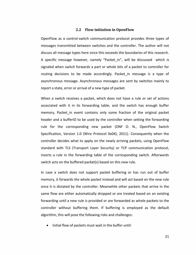
Late Packet_in: There is a possibility that the controller message is
delayed or dropped for intermediate switches on a path (from packet
source to packet destination). As an instance, if next hop (switch) in the
path is far from the controller compared to the initial switch, the following
rare but possible scenario may occur:
1. Initial switch receives the forwarding rule before the second hop
(switch) in the path does.
2. Initial switch forwards the packet to the second switch on the
path.
3. Second switch has not yet received the forwarding rule for the
subject message, either because the controller chose a longer path
for load balancing reasons, or the rule was delayed or dropped due
to buffer overflow. Thus the second switch treats the new packet
as it should and sends the packet_in request to the controller
4. Controller recalculates the rules for the subject message while the
switch is keeping it in its buffer.
23
5. This iteration repeats itself whenever the next switch in the path is
far from the controller compared to the switch sending the
packet_in message.
The “Late Packet_in” case is depicted in Figure 8.
Figure 8: Late Packet_in : Flow initiation
When huge networks of operators and access networks are considered these
risks grow proportionally. Thus it is regarded as a scalability challenge.
There have been a number of studies conducted to reduce or optimize flow
initiation process. Tootoonchian et al. (Tootoonchian, Gorbunov, & Ganjali, 2012)

24
demonstrated that this challenge can be tackled by modifying NOX controller and
introduced NOX-MT which focused on NOX controller performance and
multithreading capabilities using known techniques such as I/O Batching, etc.
Results of the mentioned study brought a magnitude of progress in controller
performance. DevoFlow (Curtis, 2011) on the other hand has proposed to handle
short-life flows by data-plane where only persistent flows are defined by
controllers. This method, supported by ASICs, forwards fewer requests to
controller alleviating flow initiation concerns. In 2010, a study on flow-based
networking, namely DIFANE is introduced, which addressed the concern with
centralized controller architectures. Yu proposed that by proactively installing all
possible rules and data-paths, partitioning these rules among switches and then
forwarding new packets to the switches containing related rules, will dramatically
lessen the switch-controller requests.
As another solution, at first glance, simply eliminating the buffering step and
sending whole new packets to the controller and forwarding those initial packets
right from the controller point until the optimal path is installed on the source
switch, might seem as an alternative solution (see Figure 11: Algorithm 2, case 1:
optimal in section 3.2.2). Advantages of this method are:
Reduction of switch buffer expenses.
The possibility to program the controller to immediately forward initial
packets it receives while flow initiation process takes place, thus
eliminating the waste of time in flow initiation and reducing the time
needed for first packets to arrive to the destination.
Reduction of the risk of Packet_in Echo scenario by reducing the risk of
buffer overflow or loss of initial packets.
The author will demonstrate that eliminating the buffering step from the default
solution for flow initiation will not provide a better solution to the above

25
mentioned risks either. Details of cases and scenarios will be presented in section
3.2 where the default algorithm fails to address flow initiation challenges in
either way: either buffering packets and sending packet header to the controller
(which will be referred to as “buffer-flow solution” in this study) or sending whole
packets to the controllers for decision making (which will be referred to as
“forward-flow solution” in this study). Afterwards another approach as a fitter
solution to the issue will be described which in essence is formed around
installing apriori information regarding the network topology on switches to
facilitate a more intelligent decision between a buffer-flow or forward-flow
solution when an unfamiliar stream of packets arrive to a switch.
The theory provided in this study as a solution will in turn face a bottleneck issue
at controller point. Although initial benchmarks of single OpenFlow controller has
demonstrated that 30000 switch requests can be handled (Tavakkoli, 2009),
replicating the controller instances eliminates this bottleneck. It is worth
mentioning that as a result of replicating controller service instances, handling
multiple controllers (service discovery, load balancing, failover, etc.) will sprung
up as a new challenge.
In case controller service is considered no different than any other service type,
SCNs or particularly Serval claim a fundamental progress in addressing the issues
related to multiple and dynamic service instances such as service discovery, load
balancing and failover scenarios. This is basically the reason why author has
decided to study controller handling in SCN also.
2.3 Controller Handling
In OpenFlow switch specification document version 1.2 mechanisms to utilize
multiple controllers were introduced. These mechanisms, which continued
through the last version of OpenFlow switch specification document version
26
1.3.2, only support controller failover and load balancing (ONF O. , 2011) (ONF O.
N., OpenFlow Switch Specification Version 1.3.2 (Wire Protocol 0x04), 2013).
Based on the latest version of the above mentioned document, a switch may
connect to several controllers. In cases of controller failure or overloading, switch
connects to alternative controllers based on installed rules. The rules involving
the multiple control handling are entirely orchestrated by controllers. Multiple
controllers connected to a switch choose a role based on the policy made by
controllers themselves. Controller roles are as follows:
Equal: This is the default role of a controller when connected to a switch.
Sending the OFPCR_ROLE_EQUAL request, the controller is given the
“Equal” role and is equal to all other controllers in the same role and has
full access and rights to the connected switch.
Master: This role is similar to the “Equal” role, except that a switch can
only have one “Master” role controller. When a controller claims this role
by sending the OFPCR_ROLE_MASTER request message, the switch
changes the role of all other Master controllers to “Slave” without
informing them.
Slave: in this role the controller has read-only access to the switch and will
not be able to alter the state of the switch. The switch on the other hand
does not send any asynchronous message to the controller in this role
except the port status message.
A switch might have multiple Equal and Slave role controllers and at most only
one Master controller.
For a switch to connect to the controller the following steps take place:
1. When the switch activates an interface or is turned on, it propagates a
“link up” message.

27
2. Controller initiates the connection to the switch by sending and receiving
hello packets and exchanging OpenFlow versions supported.
3. Switch informs the controller about its functions and status.
4. Connection establishes between controller and the switch for further
OpenFlow protocol transmissions.
This method can alternatively be performed in the service layer instead. This not
only creates a firm basis for further features of multiple controller handling such
as virtualization and dynamically distributed and specialized controller service,
but also provides a distributed service resolution mechanism that is controlled
centrally in a controller server, which is similar to the mechanism that is currently
used for out of service level routing and policy making methods.

28
3 CHAPTER THREE
THE PROPOSED TECHNIQUES
3.1 Introduction
Since OpenFlow is one of the most successful SDN implementations and
undoubtedly the most famous platform to realize SDN architecture, the author
will proceed to run simulations and implementations based on OpenFlow
framework. “Mininet” network emulator, as one of the most frequently used
emulators available, that supports OpenFlow controllers and switch instances, is
initially tested in order to check its utility in simulating virtual networks on a
single Linux based PC that can serve for the purposes of the present study.
Simulation on such a platform ensures the possibility of implementing the
outcome of the study on physical/real machines since mininet uses real Linux
kernels for hosts and real switch image: Open Virtual Switch Kernel (OVSK), for its
switches, which is built into all new Linux kernels.
3.2 Flow initiation
As stated in section 2.2 of chapter 2, flow initiation causes a considerable delay in
communication over OpenFlow based SDN model. To resolve this issue, the
author suggests the following theory:
Proactive flow installation by controller based on a function, which
decides if destinations of all possible paths are best accessed (less distant

29
and less delayed in packet transmission) by controller or the source of the
flow. This study suggests a mechanism, which involves a switch, either
local on controller machine or connected via dedicated and highly reliable
and fast link and a mechanism that uses the available network map as a-
priori knowledge in order to pre-configure switches.
In this context when destination switch is said to be “optimally accessible” by a
node it means that the communication with the destination from that node in
network takes less time. This criteria can be manipulated, however the concept is
that if a node has the most desirable path to a switch when compared to a
controller, the switch is optimally accessible by the node, and vice versa, if a
controller has the most desirable path to a switch when compared to another
node, the switch is optimally accessible by the controller.
3.2.1 Current flow initiation algorithm (Algorithm 1)
As default, OpenFlow switch description document suggests a Packet_in message
that includes a part of the header of the new packet to be sent to the controller
for decision making while packets of the new flow wait in switch buffer, until the
new forwarding rule arrives from the controller. For purpose of convenience this
algorithm will be referred to as “PIM”: Packet_In Method.
Case 1 (optimal): Desirable case for “packet_in transmission” method. In this case
since the destination access is faster from the source switch, transmission of only
the header of the packets is preferable, since packets waiting in buffer will arrive
to the destination faster and unnecessary traffic is not created from controller to
the destination switch.

30
Figure 9: Algorithm 1, Case 1: Optimal
Case 2 (non-optimal): Destination switch is accessible by the controller in less
time.
In this case since the destination is more easily accessible by the controller,
forwarding the whole packets instead of only the header is more desired.
Buffered packets will eventually have to follow a path that is easily accessible by
the controller, thus if the controller receives the whole packets it may forward
them from the controller point and may save the time it takes for the initial
switch to forward buffered packets only after receiving the forwarding rules.
Sending only the header will delay the arrival of packets to the destination.
31
Figure 10: Algorithm 1, case 2 : non-optimal
3.2.2 Sending whole packet (Algorithm 2)
An OpenFlow switch sends the whole packet to the controller for decision making
only if its buffer is missing or it is full or it is configured to do so. If this method is
not bound to the above mentioned limitations, whole packets can be sent to the
controller regardless of the buffer status. Upon receiving a new packet from a
switch, the controller not only installs new forwarding rule on switches on the
path but also forwards the packets it received during the flow initiation process.
For purpose of convenience, this algorithm can be referred to as “OFM” standing
for “original flow method”, in which packets are not buffered, instead are sent to
the controller.
Case 1 (optimal): Destination switch is accessible by the controller in less time.

32
In this case since the destination is more easily accessible by the controller,
forwarding the whole packets instead of only the header is optimal. Since
buffered packets will eventually follow a path that is easily accessible by the
controller, if the controller could have received the whole packet it could forward
them from controller point and save the time it takes for the source switch to
forward the buffered packets (after receiving forwarding rules).
Figure 11: Algorithm 2, case 1: optimal
Case 2 (non-optimal): Destination switch is accessible by the source of the flow in
less time.
In this case sending the whole packet is not desired, since the source switch has a
better condition for forwarding initial packets to destination and the path from
controller to destination is less optimized. Besides sending the header is faster
and consumes less bandwidth.

33
Figure 12: Algorithm 2, case 2: non-optimal
3.2.3 Hybrid Algorithm (Algorithm 3):
Referred to as “HYB” method for convenience, this method utilizes the cases
where previous algorithms were advantageous. As seen in previous sub-sections,
both approaches have advantages and disadvantages in certain cases. However if
switches could have an information, which is based on the topology, they can be
dictated when to use each flow initiation method. This study contributes by
suggesting that using the network map composed by statistics acquired from
switches in an SDN, controllers can install rules to determine whether a switch
should utilize PIM method (buffer the original packets) or OFM method (do not
buffer packets) when new flows arrive towards specific destinations. This
operation can be performed when controller is sprung up as follows:
1. Controller puts a table together composed of all possible subnet routes
for all the switches (based on their location in network).

34
2. Controller decides which destinations are optimally accessable by the
controller from all sources.
3. Controller installs a rule on switches dictating whole package
dissemination (Algorithm 2) in the above mentioned cases.
4. The rest of the routes are regarded by default as optimal cases and are
ordered to apply Algorithm 1.
5. These initiation rules are placed on the bottom of the flow table to allow
new rules and regulations to be placed on the top in future, preventing
their execution once new policies take effect upon actual packet arrivals.
Case 1 (optimal): Destination switch is optimally accessible to the controller.
Case 2 (optimal): Destination switch is optimally accessible to the source of the
flow.
Figure 13: Hybrid Algorithm 3 (the main contribution) Both cases : optimal
35
In this algorithm regardless of the possible cases, since the best of Algorithm 1
and 2 are chosen intelligently, all cases are optimized.
This hybrid algorithm, which is suggested in the present study, is testable using
mathematical models. However as a result of accepting the whole packets in
some cases and taking on the role of forwarding initial packets yields a
forwarding role and traffic on the controller. To resolve these issues this study
suggests that high speed packet switching functionality to be integrated on the
controller machines locally. The resulting platform will act analogous to brain in
living organisms, which not only perform decision making but also play role in
neural pulse transmission in living neural systems. As for extra traffic burden on
controller machine, this study has also conducted a literature survey to find best
practices in service handling challenges. This is basically the reason why “Multiple
Controller Handling” is being addressed by the author.
To test the above mentioned, simulation in a high-traffic large network will
demonstrate enhancement in flow initiation time compared to Algorithm 1 and
Algorithm 2.
3.2.4 Multiple Controller Handling
Since OpenFlow and any other SDN implementation for that matter implies
control functionality to be dictated by a controller to the switch fabric, it is safe to
assume control traffic as a type of service. It is necessary to keep in mind that in
order for switches and controllers to communicate on service level, both need to
have an understanding of service centric addressing scheme, namely serviceID’s
and FlowID’s as well as the network stack which processes packets containing the
above mentioned encapsulations.

36
Considering controller traffic as a type of service will allow inter-controller load
balancing and failover recovery mechanisms to be implemented inherently more
robust and secure.
The present study will not analyze the implications of implementing serval
architecture on current OpenFlow based POX controllers and effects of various
failover scenarios since the scope of the work in hand does not include how
service centric perspective introduces a redemption from techniques that are
being used for load balancing and recovery operations. This solution for
bottlenecks in controller point is solely suggested by the author based on
information derived through the literature review conducted for the main
purpose of the study. As future work however this suggestion may be applied to
demonstrate an automated and fundamentally robust process in which switches
query control planes for packet forwarding instructions. The author does not
expect a better performance in terms of controller discovery time or rate; rather
expect to end up with similar results with an IP based topology on a service
centric approach. The contribution here is to demonstrate that service centric
approach is implementable and feasible and is a fundamental solution to the
challenge.
For this method the author argues that controller handling is feasibly
implementable by the serval network stack on both controller and switches.
Controller will run POX as its network operating system and will communicate
with the switch based on serviceIDs and FlowIDs instead of IP, port and protocol
tuples.
In controller service discovery, switch receives a packet, which has no
corresponding entry to match in its flow table, encapsulates it with a service level
header and forwards it to either a service level broadcast address or its known
controller instance. Then the controller receives the enquiry and decides to de-

37
multiplex it or forward it to another controller machine based on its service
policies. Afterwards the control traffic is established accordingly.
In case of a controller failover or overload scenario, service level policies will
handle the incidence in a much similar manner when any other service type fails
or needs load balancing automatically.
Both cases above shall demonstrate Serval’s ability to handle incidents of initial
discovery and failover mechanisms of SDN based networks.
In Serval project, the authors demonstrate that service centric network and
Serval architecture function adequately and smoothly on a number of protocols
by implementing a prototype containing almost 28000 lines of code. This
prototype has demonstrated that applications like Firefox, TFTP, Iperf, Mangoose,
Apache bench, etc. are easily portable to service level operation only by changing
few lines of codes. In these prototype tests, authors have concluded with similar
results as conventional methods in protocols such as HTTP, FTP, etc. as expected
(Nordstrom, Rexford, & Freedman, 2012).
Controller service which is transmitted over OpenFlow protocol is essentially no
different than HTTP or any other protocol for that matter. Since controller service
is being introduced recently and applications using OpenFlow protocols are
numbered, it is easier to apply a service centric approach to available applications
and new features to be introduced to SDN architecture.
This will also pave the path for all other network traffics to be able to migrate to
service centric architecture since switches understand SCN addressing and
network stack schemes.

38
4 CHAPTER FOUR
SIMULATION BASED ASSESSMENT OF PROPOSED TECHNIQUES
4.1 Algorithm expression
For any arbitrary topology, the Hybrid Algorithm will find the best method of flow
initiation regardless of the location of the controller, source and destination
hosts. This hybrid algorithm, being intuitively evident, can also be explained as
follows:
As discussed in section 3.2 we can conclude that the time required for initial
packets of new and unknown flows to reach their destination in Algorithm 1 Case
1 and Algorithm 2 Case 1 are smaller than Case 2 respectively.
For convenience the following reference table is constructed:
Table 2: Scenario specific flow initiation time reference
Scenario Time needed for initial packets of
unknown flows to reach
destination.
Algorithm 1 Case 1
Algorithm 1 Case 2
Algorithm 2 Case 1 ’
Algorithm 2 Case 2 ’

39
If the following assumption is made for both algorithms:
In a single topology:
If the probability of Case 1 incident equals , then the probability of Case 2
incidents are equal to in each algorithm.
Then we can conclude that the expected values of initial packet latency (average
time needed for initial packets to arrive destination) during flow initiation for all
three algorithms are as following:
{ }
{ }
{ }
Thus we can conclude that:
Since and at the same time
Then:
{ } { }
{ } { }
The present study also provides simulation results for all the above mentioned
cases and concludes that Hybrid algorithm provides enhancements over both
Algorithms 1 and 2.
Literature survey also supports the suggested method to resolve controller
congestion issue by resorting to multiple controllers and handling them by service
centric architecture and mechanisms.
40
4.2 Simulation
In order to simulate OpenFlow and SDN concepts there are in total three
simulators available, namely EstiNet, MiniNet and NS3. Before reviewing each
simulator it is important to stress the basic and fundamental necessity of the
present study in order to demonstrate merits of HYB method. First and foremost,
the controller in the setup of the network for this study will need to operate in an
“in-band” mode. In-band control in this context means that the controller will use
the same medium-channel for control traffic and data traffic. (data and control
traffic are transmitted on the same network.)
4.2.1 EstiNet
EstiNet is a simulator/emulator which allows its users to use both of its
capabilities. However, it is a proprietary and it is indeed an expensive
simulator/emulator for the purposes of the present study, and hence is not used
here. In addition, Esti-Net is not set up to utilize in-band controller mechanisms
out of the box and modifications in source code are necessary (information based
on the email reply from the developer team of EstiNet).
4.2.2 Mininet
Mininet is a considerably fast to deploy emulator and it is easy to test openflow
setups in mininet. The author has started the present study utilizing mininet for
experimental purposes. However, since its documentation in general and its
functionality assessment in particular are very limited, it was not obvious in the
short term that mininet will not serve for the purpose of the present study. The
reasons why we did not use mininet in the present study are as follows:
Mininet has few components to support in-band controllers, which is
necessary for this study. There is no method to define and use a
controller, which is also used for data transmission. Provided controller
41
classes and switches all utilize out-band control mechanisms, which
means all switches and controllers are connected to each other on a
network separate from the actual data network.
We changed the component codes in mininet so that it will provide in-
band control mechanisms, however since mininet controller and switches
are not created for hybrid-networks (networks which control and data
signals are on the same sets of connections and network), mininet
emulator demonstrated unexpected results and performance. Technically
speaking, the code for mininet generated unnecessary recursive outputs.
The controller, as a result of being not programmed to handle in-band
controlling mechanisms repeatedly logged following messages:
o |99097|poll_loop|DBG|[POLLIN] on fd 7:
o |99098|poll_loop|DBG|[POLLIN] on fd 8:
o |99106|vconn|DBG|Dropped 9272 messages in last 1
seconds due to excessive rate
It indicated great amount of packet loss due to the recursion taking place
in the controller. In short the fact that the controller and switches in
mininet are not optimized for in-band traffic created this excessive traffic.
In mininet all switches and controllers are in the same namespace sharing
same processes as the host computer. Only user space switches are
compatible with separate namespace capability which cannot be used for
remotely controlled in-band controllers.
4.2.3 NS3
NS3 provides modules for OpenFlow and SDN networks, however thanks to its
comprehensive and solid documentation, in process of testing, it became quickly
evident that NS3 does not support in-band controlling mechanisms for switches
and remote controllers (ns3). Each switch in NS3 has its own class of controller,
which is connected via a loopback interface on the same switch, therefore
remote connection and link failure scenarios cannot be implemented.

42
Initially it seems as the best solution to modify codes of switches and controllers
in NS3 to accommodate the purposes of the present study, however due to the
complex nature of written codes for switches and controllers in NS3 it is
necessary to have adequate knowledge on all aspects and classes in components
of NS3 to change a behavior in a module. Since most of the capabilities of
modules in NS3 are not necessary for this study and are out of the scope of the
present work, this solution was discarded. However it is also indicated in the
development documentation that remote controllers can be an option for future
development projects and are welcomed by the developer team of NS3.
4.2.4 Simulation Tools
Since available simulation/emulation tools could not be used for the purpose of
this study, the authors have developed a new simulator, which would serve for
the purpose of the present work.
In order to provide compatibility and ease of porting to NS3, initially C++ was
chosen as the language of programming. A program consisting of over 2900 lines
of C++ code is written to simulate a network with SDN capabilities. However since
the garbage collection is not handled automatically in C++, especially when raw
pointers are used, the program demonstrated unexpected crashes and memory
leaks during the experiments.
In order to demonstrate effects of the hybrid flow initiation mechanism, the
authors re-wrote the whole simulator program from scratch in Python language,
which provides automatic and efficient garbage collection mechanisms and has a
less steep curve of programming and exception handling processes. This removes
the risk of constant crashes during experiments and provides adequate
performance metrics to test different scenarios.

43
The Python code for this simulation consisting of over 1500 lines of code using
Python 2.7 codes is used to carry out experiments to evaluate our proposal in this
study.
As a platform on which the code will run, authors have chosen GNU/Linux Debian
on a dual-core 2.6 Gigahertz CPU computer which uses 4 Gigabytes of RAM. Linux
distribution is selected since it provides full utilization of multi-threading and
concurrency and is easier to setup compared to UNIX and UNIX based operating
systems.
In Figure 14 the preliminary class diagram for the simulator indicates that the
simulator is designed only to serve for the purposes of this study, however other
types of uses can be derived based on its capabilities.
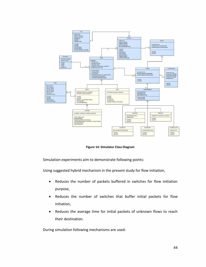
44
Figure 14: Simulator Class Diagram
Simulation experiments aim to demonstrate following points:
Using suggested hybrid mechanism in the present study for flow initiation,
Reduces the number of packets buffered in switches for flow initiation
purpose,
Reduces the number of switches that buffer initial packets for flow
initiation,
Reduces the average time for initial packets of unknown flows to reach
their destination.
During simulation following mechanisms are used:

45
Overall architecture: Authors have put effort to model the characteristics
and features of the simulator as close to real networks as it is useful for
the purposes of the present study. Overall architecture of the simulator is
as follows:
o Node Types:
Hosts: nodes with one interface (NIC), one forwarding table
(network route to and from the default gateway), sending
and receiving echo applications and replying to ingress
echo messages.
Switches: nodes with multiple interfaces, multiple flow
tables, echo sending/receiving applications and controller
communication applications.
Controllers: nodes that are inherently capable of switching,
plus routing, flow modification, receiving interface statistics
from switches, applications for sending and receiving echo
messages and communicating on control features with
switches.
o Interfaces: each node on network can install one or more network
interface card in order to connect to network Links. Each interface
has bandwidth parameter that can be set individually.
o Interface Address: each interface can have two types of address:
Hardware address: can be assumed and be utilized as MAC
address.
Software address: can be assumed and be utilized as IP
address, IPv4, IPv6 or any arbitrary address type.
o Network Links: each network link, similar to network cable,
connects two Network Interface Cards to each other and has a
random and configurable link delay capability.
46
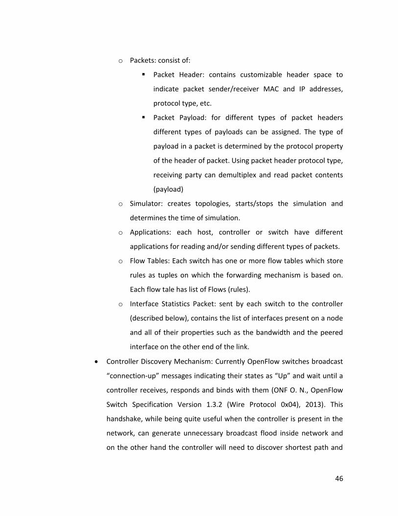
o Packets: consist of:
Packet Header: contains customizable header space to
indicate packet sender/receiver MAC and IP addresses,
protocol type, etc.
Packet Payload: for different types of packet headers
different types of payloads can be assigned. The type of
payload in a packet is determined by the protocol property
of the header of packet. Using packet header protocol type,
receiving party can demultiplex and read packet contents
(payload)
o Simulator: creates topologies, starts/stops the simulation and
determines the time of simulation.
o Applications: each host, controller or switch have different
applications for reading and/or sending different types of packets.
o Flow Tables: Each switch has one or more flow tables which store
rules as tuples on which the forwarding mechanism is based on.
Each flow tale has list of Flows (rules).
o Interface Statistics Packet: sent by each switch to the controller
(described below), contains the list of interfaces present on a node
and all of their properties such as the bandwidth and the peered
interface on the other end of the link.
Controller Discovery Mechanism: Currently OpenFlow switches broadcast
“connection-up” messages indicating their states as “Up” and wait until a
controller receives, responds and binds with them (ONF O. N., OpenFlow
Switch Specification Version 1.3.2 (Wire Protocol 0x04), 2013). This
handshake, while being quite useful when the controller is present in the
network, can generate unnecessary broadcast flood inside network and
on the other hand the controller will need to discover shortest path and
47
statistics to each switch separately. Since the suggested flow initiation
mechanism in the present study is agnostic to the underlying topology
and controller discovery mechanisms, authors are suggesting a different
controller mechanism in order to create an autonomous controller
discovery method, authors have implemented following algorithm:
o Upon initialization, switches stay in listening mode.
o Upon initialization, controller broadcasts a packet containing the
address of the controller and hops (intermediary nodes) to reach
the controller (initiated by the controller as being zero). For
convenience this packet is called the “controller beacon” in the
present study.
o Each switch, upon receiving the controller beacon checks to see if
it has already received a controller beacon from another source.
o If the switch has already received a beacon, checks if its
“hops_to_controller” parameter is less than the newly received
beacon’s “hops_to_controller” parameter.
If newly received beacon is from a closer source to the
controller, the switch re-sets its controller access address
and “hops_to_controller” parameters based on the new
beacon, creates a new beacon with augmented
“hops_to_controller” propery and broadcasts the beacon
packet from all of its interfaces except the ingress port.
Otherwise, the switch discards the new beacon packet.
Network Discovery: Each switch, upon setting up its controller access
parameters based on received beacons, sends an “interface_statistics”
message out of its controller access interface (which was set as the ingress
interface of the beacon packet). Since the other switch sitting on the
other end of the line also knows which interface finally leads to the

48
controller, the “interface_statistics” packet finds its way to the controller.
This way the controller also acquires knowledge of the whole network
without the need for all switches to broadcast their status. Since all
control access interfaces on all switches are best interface to access
controller (determined by the controller discovery method described
above), “interface_statistics” packets are directed to the controller via the
shortest path without the need for any calculation.
With the above features, authors have aimed to provide a solid and minimal way
for the simulator to provide an experiment environment for purposes of the
present study.
4.2.5 Experiments
The present part of our study aims to demonstrate the differences in three
algorithms analyzed in the previous sections. In each experiment, the numbers
provided are average of three iterations of execution.
Experiment 1: Linear topology with 2 switches
To begin with, a topology consisting of 2 switches and 2 hosts is considered as
depicted in Figure 15. In experiments 1, two hosts in this topology send echo
packets to one another. In each experiment, h1 attempts to send an echo packet.
After the corresponding flow initiation mechanism takes place, the actual
transmission begins. When h2 receives the echo packet, it immediately composes
an echo reply packet and attempts transmitting it to the IP address, which sent
the original echo packet. This transmission of echo reply packet will in turn be
preceeded with a flow initiation process for its own flow type, source and
destination co-ordinates. Latency, which is the time difference between the
transmission of echo packet and the reception of the echo reply packet by h1, is

49
taken as the primary parameter to be considered for our experimental
evaluation. Only 100 Mbps connections are used in this experiment
Figure 15: Experiment 1
The purpose of this experiment is to demonstrate that HYB and OFM are
approximately equal in terms of latency in this topology. However, the PIM
method (buffering initial packets in source switch) performs poorly when
compared to other two methods of flow initiation.
340000 350000 360000 370000 380000 390000 400000 410000 420000
Iteration 1
Iteration 2
Iteration 3
Iteration 4
Latency (microseconds)
Experiment 1
HYB
OFM
PIM

50
The clear reason for this result to appear is that the destination is more quickly
accessed by the controller, thus sending the Original Flow to the controller
eliminates the time needed for waiting for flow initiation and retransmitting the
echo packet once rules are installed by the controller.
Experiment 2: Linear topology with 4 switches
The purpose of this experiment is to demonstrate that by growing the network in
size for linear topologies, the effect of HYB method magnifies and still the
difference between the evaluation result for OFM and HYB methods stays close
with a clear advantage on HYB method. The reason for this advantage will be
discussed in section 14.2.6. Only 100 Mbps connections are used in this
experiment.
Figure 16: Experiment 2

51
As seen above while HYB and OFM methods outperform the PIM method, the
difference between their performances has grown, which is expectable due to
more distant sender and receivers of echo packet.
Experiment 3: Linear topology with 8 switches
The purpose of this experiment is to demonstrate the continuity in the advantage
of utilizing OFM and HYB methods and to demonstrate the effect of growth in
network size on this advantage. Only 100 Mbps connections are used in this
experiment.
0 200000 400000 600000 800000 1000000 1200000
Iteration 1
Iteration 2
Iteration 3
Iteration 4
Latency (microseconds)
Experiment 2
HYB
OFM
PIM

52
Figure 17: Experiment 3
This experiment will also act as a base for further experiments where PIM
presents more advantageous results when compared to OFM but still falls short
when compared to HYB method.
0 500000 1000000 1500000 2000000 2500000 3000000 3500000
Iteration 1
Iteration 2
Iteration 3
Iteration 4
Latency (microseconds)
Experiment 3
HYB
OFM
PIM

53
As clearly seen above, the time difference between sending echo and receiving
echo packets using HYB and OFM is almost half the value for PIM method. This
growth expressively indicates that with growing number of nodes in a linear
topology with a controller in middle, HYB and OFM methods yield a considerable
gain with regards to the time needed for initial packets of unknown flows to
reach their destinations.
Experiment 4: Non-linear topology with multiple loops
When single or multiple loops are introduced in the network, the effect of HYB
method becomes bolder as it outperforms both OFM and PIM.
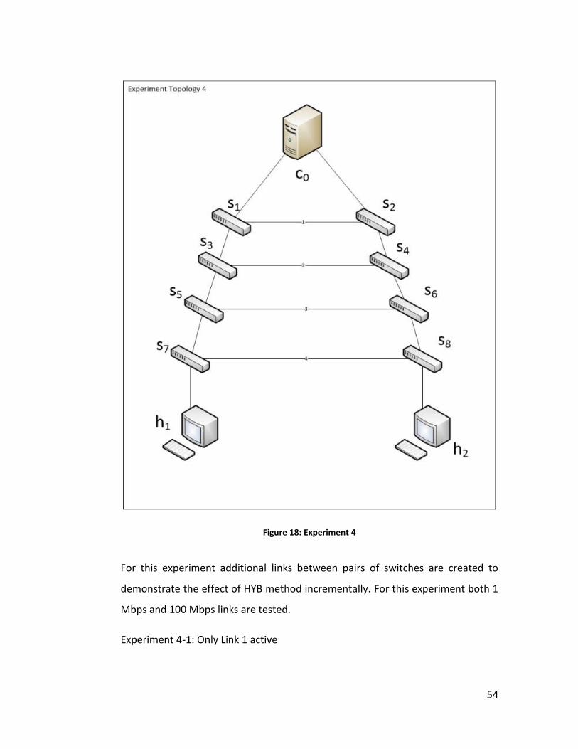
54
Figure 18: Experiment 4
For this experiment additional links between pairs of switches are created to
demonstrate the effect of HYB method incrementally. For this experiment both 1
Mbps and 100 Mbps links are tested.
Experiment 4-1: Only Link 1 active

55
Experiment 4-2: Link 1 and link 2 active
Experiment 4-3: Link 1, 2 and link 3 active
0 10000000 20000000 30000000 40000000
100 Mbps
1 Mbps
Latency (microseconds)
Experiment 4-1
HYB
OFM
PIM
0 5000000 10000000 15000000 20000000 25000000 30000000
100 Mbps
1 Mbps
Latency (microseconds)
Experiment 4-2
HYB
OFM
PIM

56
Experiment 4-4: all 4 links active
As a clear indication, all four experiments demonstrate that the HYB method is at
least as fast as other two methods.
0 5000000 10000000 15000000 20000000 25000000 30000000
100 Mbps
1 Mbps
Latency (microseconds)
Experiment 4-3
HYB
OFM
PIM
0 5000000 10000000 15000000 20000000 25000000 30000000
100 Mbps
1 Mbps
Latency (microseconds)
Experiment 4-4
HYB
OFM
PIM

57
By activating intermediary links one by one, the topology changes. As a result, in
each step, the sender and receiver of the echo packet get closer to each other
and the controller falls far to the destination compared to the source in the last
experiment (4-4). The expected result is that in first experiment PIM method to
fall short and OFM and HYB to perform better, and in last experiment to observe
that the PIM and HYB methods to outperform the OFM method, which is exactly
what results yield in terms of the time needed for initial echo packets to reach
destination. This gradual change in the topology is a direct lead to demonstrate
to consistent efficiency of the HYB method.
Experiment 5: Arbitrary topology with multiple loops
In order to demonstrate the utilization comparison among flow initiation
methods, this experiments takes an arbitrary network topology and performs
various echo experiments between pairs of hosts.
Figure 19: Experiment 5
For purpose of demonstrating the buffer usage of the switches in topology in
each flow initiation method, the topology in Figure 19 is created on the simulator.
The exact interface connection of the topology above is demonstrated in Figure
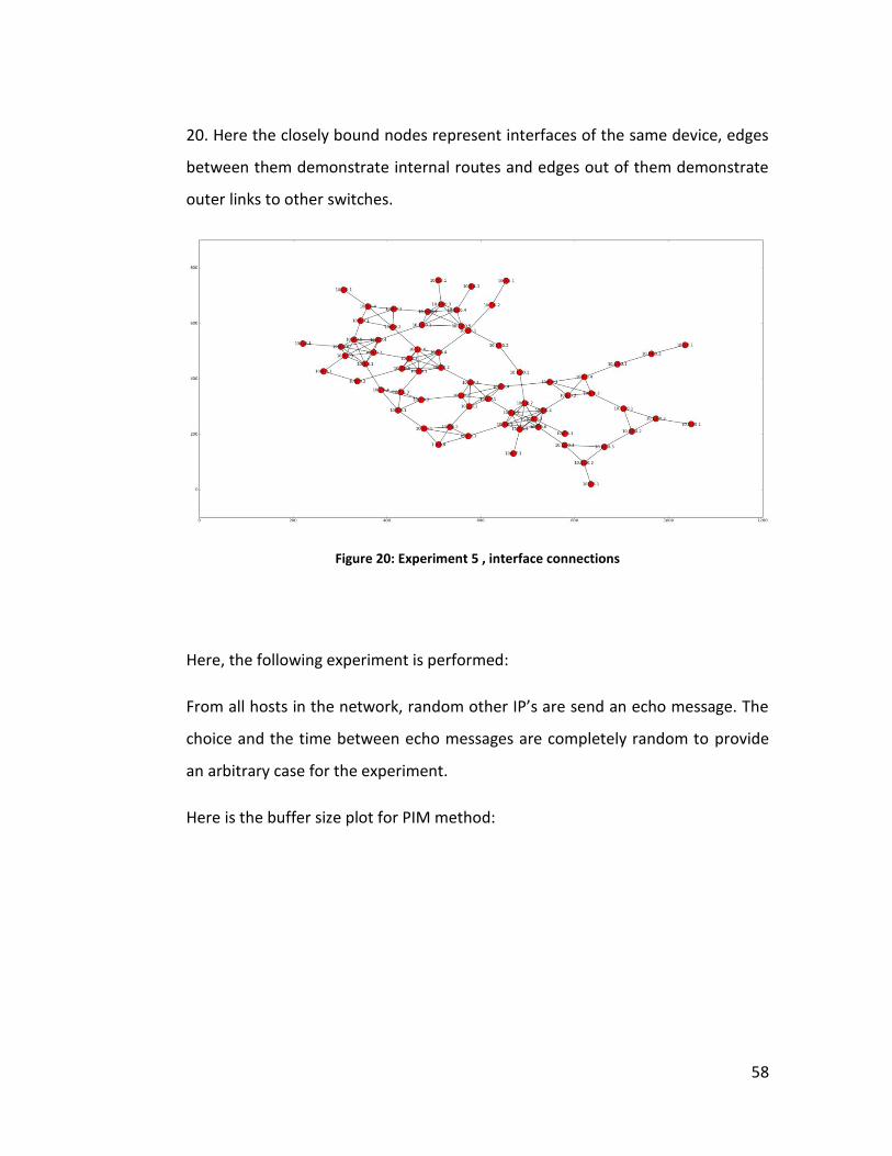
58
20. Here the closely bound nodes represent interfaces of the same device, edges
between them demonstrate internal routes and edges out of them demonstrate
outer links to other switches.
Figure 20: Experiment 5 , interface connections
Here, the following experiment is performed:
From all hosts in the network, random other IP’s are send an echo message. The
choice and the time between echo messages are completely random to provide
an arbitrary case for the experiment.
Here is the buffer size plot for PIM method:

59
Figure 21: Buffer Size plot for all switches in network when PIM method is used
Here is the buffer size plot for PIM method:
Figure 22: Buffer Size plot for all switches in network when Hybrid method is used

60
As can be derived from the comparison between Figure 21 and Figure 22 , where
each color of line indicate a switch in topology, in a 5 minute run, where hosts
constantly echo random destinations:
In HYB method less number of switches are needed to buffer packets.
The maximum number of buffered packets reach 9 packets in PIM where
HYB method tops only 4 packets.
In HYB method only few switches intensively use buffer, and much
frequently empty their buffers leaving more space and less requirement
for buffer space and less possibility of buffer overflow.
Needless to say, OFM method does not allow switches to buffer packets, thus is
not plotted.
Following experiments are applied to demonstrate the efficiency of HYB method
once again in initial packet delivery time, however this time in an arbitrary
network.
The average of number of events regarding sending (Blue color) and receiving
(Green color) echo packets is plotted below:
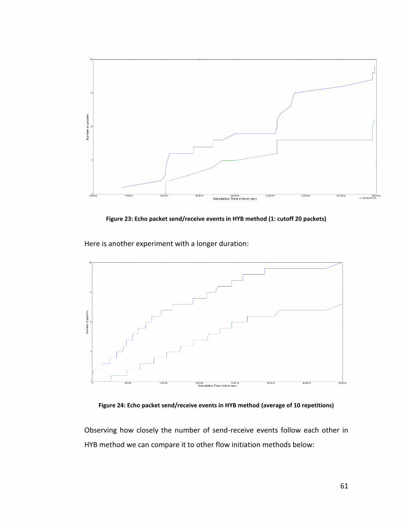
61
Figure 23: Echo packet send/receive events in HYB method (1: cutoff 20 packets)
Here is another experiment with a longer duration:
Figure 24: Echo packet send/receive events in HYB method (average of 10 repetitions)
Observing how closely the number of send-receive events follow each other in
HYB method we can compare it to other flow initiation methods below:
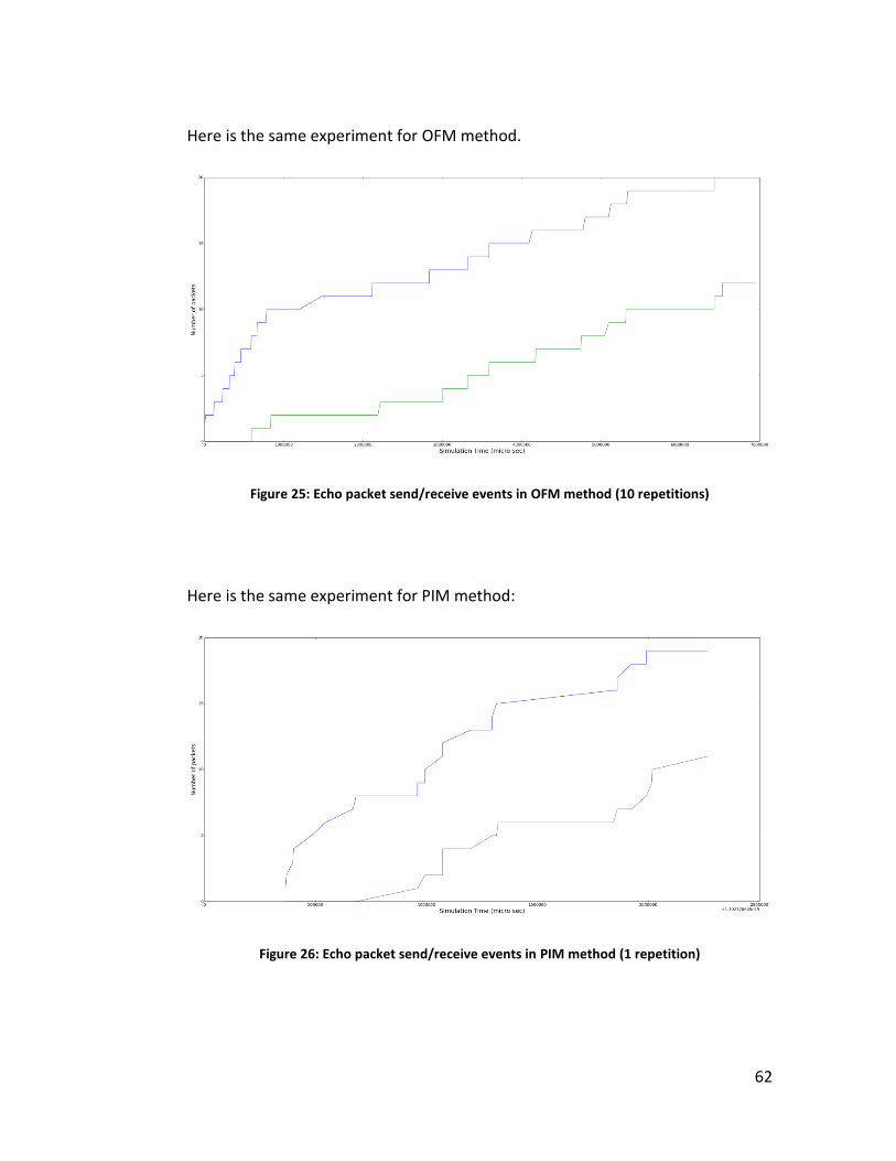
62
Here is the same experiment for OFM method.
Figure 25: Echo packet send/receive events in OFM method (10 repetitions)
Here is the same experiment for PIM method:
Figure 26: Echo packet send/receive events in PIM method (1 repetition)
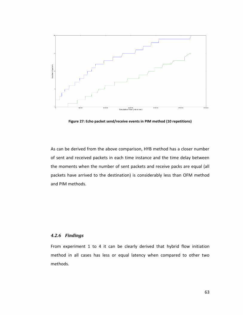
63
Figure 27: Echo packet send/receive events in PIM method (10 repetitions)
As can be derived from the above comparison, HYB method has a closer number
of sent and received packets in each time instance and the time delay between
the moments when the number of sent packets and receive packs are equal (all
packets have arrived to the destination) is considerably less than OFM method
and PIM methods.
4.2.6 Findings
From experiment 1 to 4 it can be clearly derived that hybrid flow initiation
method in all cases has less or equal latency when compared to other two
methods.

64
A comment that is worth mentioning is that in experiment 4 as more links are
added that shortens the path between hosts, PIM and HYB methods’
performance gets closer and when less number of such links are activated
meaning that hosts are further apart from each other OFM performance is almost
the same as the other two. This is expected because when hosts are close to each
other OFM is not a desirable flow initiation method.
During experiment 5 authors concluded that the HYB method yields a
considerable enhancement over buffer size and buffer usage in networks when
compared to the PIM method. It is also evident from the comparisons between
the echo send-receive time analysis of all three methods, HYB method of flow
initiation on average provides means that enable initial packets of unknown flows
to reach their destination quicker.
4.3 DISCUSSION
4.3.1 Economic influences
The present study does not aim to analyze monetary and economic implications
of suggested methods. Production or configuration of switch-capable controller
machines, bandwidth expenses and buffer expenses will all have influence on the
selection of the optimal choice.
4.3.2 Implications of controller platforms with switch capabilities
As was discussed briefly in section 3.2.3 a platform with high speed switching
capabilities and controller functionalities might at first seem like taking a step
backwards to conventional networks. However, this study does not suggest
coupling control and data planes in a single device again. Instead, two distinct

65
planes of the suggested platform will continue negotiating still based on SDN
principles. The co-existence of those two functionalities on a single device,
however will provide a communication speed that is incomparable to remote
controller and switches over the network.

66
5 CHAPTER FIVE
5.1 CONCLUSION
Software Defined Networking as a considerably new principle has evolved the
way networks operate and has brought unprecedented innovation pace into the
field of computer networks. However similar to almost any new concept, it has its
own challenges.
One of the challenges unique to Software Defined Network architecture is to
reduce the time needed for flow initiation for new arrival packets. For this
challenge, the present study proposes a hybrid solution which takes advantages
of previously implemented algorithms and uses the internal network topology
knowledge of controllers to decide when to utilize the advantageous one to
achieve an optimal flow initiation time.
This study has also argued that using service centric approach to resolve multiple
controller challenges is as applicable as any other distributed service over the
network.
Although proposed concepts are intuitively logical, simulations are conducted to
support findings and arguments of this study in practice.
The simulation experiments solidly conclude a sustaining and consisting
advantage when the suggested Hybrid flow initiation method is utilized. Hybrid
method provided less need for buffer and also quicker packet arrival time during
flow initiation in an SDN.
67
When Hybrid method is used, the controller provided rules to switches prior to
their request to ask for one of these flow initiation methods:
For farther destinations, don’t buffer packet, send the original flow to the
controller unless told otherwise later.
For closer destinations, buffer the packet, wait for flow initiation to
conclude.
This way switches could save time during flow initiation and used less buffer size
to hold initial packets.
The implications of this suggested method is:
Less buffer expenses and resources needed in switches.
Quicker results on flow initiation process.
Less buffer overflow possibilities and thus less packet transmission
failures.
5.2 FUTURE WORKS
NetBrain: The author will enhance the study over the possibility and implications
of prototyping a platform on which controller functions communicate with a high
speed switch local to the device. This platform for its analogy to function as the
brain in neural systems can be seen as the Network Brain.
Technological requirements, Hardware and Software design aside, involve
utilization of new methods and algorithms as well as mechanisms currently used
in computer science, to enhance the overall reliability and performance of
software defined networks.

68
The code for the simulation will be optimized for further use, and will be put
online as an open source project to serve for other researches in SDN area.

69
REFERENCES
Beacon. (n.d.). Home Page. (Stanford) Retrieved from openflow.stanford.ed:
https://openflow.stanford.edu/display/Beacon/Home
Brandon, H. (2013). Leveraging SDN Layering to Systematically Troubleshoot
Networks. 37-42.
Carzaniga, A., Wolf, A., & Rutherford, M. (2004). A Routing Scheme for Content-
Based Networking. IEEE INFOCOM, (pp. 918-928).
Cheriton, D., & Gritter, M. (2000). TRIAD: a Scalable Deployable NAT-based
Internet Architecture. Retrieved from http://www-dsg.stanford.edu/triad/
Curtis, A. (2011). DevoFlow: Scaling Flow Management for High-Performance
Networks. SIGCOMM’11 (pp. 254-265). ACM .
D’Ambrosio, M., & et., a. (2011). MDHT: A Hierarchical Name Resolution Service
for Information-Centric Networks,”. ACM SIGCOMM Wksp. Information-
Centric Networking, (pp. 7-12).
Feamster, N., Balakrishnan, H., & Rexford, J. (2004). The case for separating
routing from routers. Proceedings of the ACM SIGCOMM workshop on
Future directions in network architecture - FDNA '04, 5-12.
Freedman, M. J., Arye, M., Gopalan, P., Y. Ko, S., Nordström, E., Rexford, J., &
Shue, D. (2010). Service-Centric Networking with SCAFFOLD. Princeton
University, Department of Computer Science.

70
Kim, H., & Feamster, N. (2013). Improving network management with software
defined networking. IEEE Communications Magazine, 114-119.
Koponen, T., Chawla, M., & Chun, B.-G. (2007). A Data-Oriented (and Beyond)
Network Architecture. SIGCOMM’07, (pp. 114-119).
Lagutin, D., Visala, K., & Tarkoma, S. (2010). “PSIRP Perspective”: Towards the
Future Internet Emerging Trends from European Research., (pp. 75–84).
Maestro. (n.d.). Maestro-platform. Retrieved from Google Codes:
http://code.google.com/p/maestro-platform/
McKinney, R. D., Montgomery, W. A., Ouibrahim, H., Sijben, P., & Stanaway, J. J.
(1998). Service-Centric networks. Bell Labs Technical Journal, 98-115.
Nicira. (n.d.). NOXRepo. (Nicira) Retrieved from NOXRepo:
http://www.noxrepo.org/
Nick McKeown, M. C. (2007). Ethane: Taking Control of the Enterprise. ACM
SIGCOMM Computer Communication Review, Vol. 37, No.4 (pp. 1-12).
ACM.
Nordstrom, E., Rexford, J., & Freedman, M. J. (2012). Serval: An End-Host Stack
for Service-Centric Networking. 9th USENIX Symposium on Networked
Systems Design and Implementation (NSDI ’12), (pp. 1-14).
ns3. (n.d.). ns-3 vns-3-dev documentation. Retrieved February 2014, from
http://www.nsnam.org/docs/release/3.13/models/html/openflow-
switch.html
ONF, O. (2011, december). OpenFlow Switch Specification v. 1.2.0. Retrieved
from https://www.opennetworking.org/images/stories/downloads/sdn-
resources/onf-specifications/openflow/openflow-spec-v1.2.pdf

71
ONF, O. N. (2011, febuary). OpenFlow Switch Specification, Version 1.0 (Wire
Protocol 0x04). Retrieved from
http://www.openflow.org/documents/openflow-spec-v1.1.0.pdf
ONF, O. N. (2013, April). OpenFlow Switch Specification Version 1.3.2 (Wire
Protocol 0x04). Retrieved from
https://www.opennetworking.org/images/stories/downloads/sdn-
resources/onf-specifications/openflow/openflow-spec-v1.3.2.pdf
OpenFlow. (2013, August). Controller Performance Comparisons. Retrieved from
http://archive.openflow.org/wk/index.php/Controller_Performance_Com
parisons
Rexford, J. (2012). First Speech: Software Defined Service-Centric Networking.
Open Networking Summit '12.
Tavakkoli. (2009). Applying NOX to the Datacenter. Proc. ACM HotNets-VIII Wksp.
Tootoonchian, A., Gorbunov, S., & Ganjali, Y. (2012). On Controller Performance
in Software-Defined Networks. USENIX Hot-ICE '12, (pp. 10-15).
Yang, D., & Anderson, G. (2004). Forwarding and Control Element Separation
(ForCES) Framework, RFC 3746.
Yeganeh, S. H., Tootoonchian, A., & Ganjali, Y. (2013). On Scalability of Software-
Defined Networking. (pp. 136-141). IEEE Communications Magazine, Feb
2013.

1
TEZ FOTOKOPİSİ İZİN FORMU
ENSTİTÜ
Fen Bilimleri Enstitüsü
Sosyal Bilimler Enstitüsü
Uygulamalı Matematik Enstitüsü
Enformatik Enstitüsü
Deniz Bilimleri Enstitüsü
YAZARIN
Soyadı : SOLTANI …..…………………………………………………………………….
Adı : Ahmad ...………………………………………………………………………….
Bölümü : Information Systems …….……………………………………………………...
TEZİN ADI (İngilizce) : FLOW INITIATION IN SOFTWARE DEFINED NETWORKING
………………………………………………………………………………………………
………………………………………………………………………………………………
……………………………………………………………………………………………...
TEZİN TÜRÜ : Yüksek Lisans Doktora
1. Tezimin tamamından kaynak gösterilmek şartıyla fotokopi alınabilir.
2. Tezimin içindekiler sayfası, özet, indeks sayfalarından ve/veya bir bölümünden
kaynak gösterilmek şartıyla fotokopi alınabilir.
3. Tezimden bir (1) yıl süreyle fotokopi alınamaz.
TEZİN KÜTÜPHANEYE TESLİM TARİHİ : …………………….


![Dr. SOLTANI LA CINÉTIQUE CHIMIQUE - Université de Sétif agro... · 2020. 6. 25. · Dr. SOLTANI 5 graphique de 1/[A] en fonction du temps et qu’on obtient une droite, la réaction](https://img.dokumen.tips/doc/110x75/611d1cf32292837cf4205ae9/dr-soltani-la-cintique-chimique-universit-de-stif-agro-2020-6-25.jpg)