Embed Size (px)
Citation preview
10FTM04
AGMA Technical Paper
Low Distortion HeatTreatment ofTransmissionComponentsBy Dr. V. Heuer and Dr. K. Löser,ALD Vacuum TechnologiesGmbH, D.R. Faron, GeneralMotors, and D. Bolton, ALD-TT

Low Distortion Heat Treatment of Transmission Components
Dr. Volker Heuer and Dr. Klaus Löser, ALD Vacuum Technologies GmbH,Donald R. Faron, General Motors, and David Bolton, ALD-TT
[The statements and opinions contained herein are those of the author and should not be construed as anofficial action or opinion of the American Gear Manufacturers Association.]
AbstractIn many applications the high demands regarding service life of transmission components can be reachedonly by the application of a customized case hardening. This case hardening process results in a wearresistant surface-layer in combination with a tough core of the component.
However as a side-effect the components get distorted during heat treatment. This distortion has a significantcost-impact, because distorted components often need to be hard-machined after heat treatment. Thereforethe proper control of distortion is an important measure to minimize production costs.
By applying the technology of low pressure carburizing (LPC) and high pressure gas quenching (HPGQ) heattreat distortion can be significantly reduced.
HPGQ provides a very uniform heat transfer coefficient. The predictability of movement during quenching ismore certain and uniform throughout the load. Further improvements can be achieved by “DynamicQuenching” processes where the quenching severity is varied during the quench sequence by step control ofthe gas velocity. Proper fixturing is another factor for distortion control. Modern CFC-materials (carbonreinforced carbon) are well suited as fixture-material for gas quenching.
The paper presents how LPC and HPGQ processes are successfully applied on Internal ring gears for a 6speed automatic transmission. The specific challenge in the heat treat process was to reduce distortion insuch a way that subsequent machining operations are entirely eliminated. As a result of extensivedevelopment in the quenching process and the use of specialized CFC- fixtures it was possible to meet thedesign metrological requirements.
The Internal ring gears addressed in this report have been in continuous production since 2006. Subsequenttesting and monitoring over a two year period progressively demonstrated that consistent metrology wasachieved and quality inspection was reduced accordingly.
Copyright 2010
American Gear Manufacturers Association500 Montgomery Street, Suite 350Alexandria, Virginia, 22314
October 2010
ISBN: 978--1--55589--979--0

3
Low Distortion Heat Treatment of Transmission Components
Dr. Volker Heuer and Dr. Klaus Löser, ALD Vacuum Technologies GmbH,Donald R. Faron, General Motors, and David Bolton, ALD--TT
Introduction
Proper distortion control has become even moreimportant than in previous days. To answer thedemand for fuel--efficient vehicles, moderntransmissions are built much lighter. Therefore thecomponents of the transmission exhibit less wall--thickness which makes them more sensitive todistortion. Distorted gear components cause noisein the transmission, can require post heat treatmachining processes and may even create prob-lems during transmission--assembly. Thereforedistortion control has become more important thanever.
By applying the technology of Low PressureCarburizing (LPC) and High Pressure Gas Quench-ing (HPGQ) heat treat distortion can be significantlyreduced. LPC is a case hardening process which isperformed in a pressure of only a few millibar usingacetylene as the carbon source in most cases.During HPGQ the load is quenched using an inertgas--stream instead of a liquid quenching media.Usually nitrogen or helium are used as quench gas.
With an optimized distortion control it is possible tosimplify the process chain significantly. Figure 1shows how the process chain can be simplified, ifthe specified geometrical values of the componentscan be guaranteed after gas quenching.
If the simplified process chain can be applied, thenthis will result in lower costs per part, lower through-
put times and lower energy consumption duringproduction. Since there is no need to dispose anyoil after the quench and since cleaning operationsafter the quench are unneeded, the simplifiedprocess chain is much more environmentallyfriendly as well.
For the Internal ring gears addressed in this report,the parts used to be heat treated with an inductionhardening--process. This process requires a 50carbon and high alloy steel--grade, which is verychallenging for machining, or a non--ferritic grade ofcast iron, which is challenging for casting. So theintent was to change from induction hardening tocase hardening and to guarantee a low level ofdistortion after case hardening, to allow for directassembly into transmission.
Distortion mechanisms
The plastic deformation of metallic componentsduring heat treatment is referred to as distortion.Distortion occurs if the stress in the material ex-ceeds the yield stress of the material. During casehardening the components are exposed to hightemperatures in the range of 880C to 1050C andthe yield stress decreases strongly with increasingtemperature of a component. Three different typesof stress in the material need to be distinguished:
-- Residual stresses (they are induced before heattreatment by casting, forging, machining etc.).[1]
Figure 1. Conventional and new process chain for the manufacturing of gear components

4
-- Thermal stresses (they are caused by thetemperature gradient while heating andquenching).
-- Transformation stresses (they are caused bythe transformation from ferrite to austenite dur-ing heating and transformation from austenite tomartensite/bainite during quenching).
These three types of stresses overlay with eachother and add up to the total stress in thecomponent. They are influenced by part--geometry,steel--grade, casting, forging, machining etc., andthey depend on the heat treatment. If the totalstress in the component exceeds the yield stress,then plastic deformation (distortion) of thecomponent takes place. The chronology and theheight of the three types of stresses leading to dis-tortion are dependent on numerous differentfactors, see Figure 2.
High pressure gas quenching (HPGQ)
The technology of high pressure gas quenching(HPGQ) offers a tremendous potential to reduceheat treat distortions. Conventional quenching--technologies such as oil-- or polymer--quenching
exhibit very inhomogeneous cooling conditions.Three different mechanisms occur duringconventional liquid quenching: film--boiling, bubble--boiling and convection. Resulting from these threemechanisms the distribution of the local heattransfer coefficients on the surface of thecomponent are very inhomogeneous. Theseinhomogeneous cooling conditions cause tremend-ous thermal and transformation stresses in thecomponent and subsequently distortion. DuringHPGQ only convection takes place which results inmuch more homogenous cooling--conditions, seeFigure 3.
Significant reductions of distortion by substitutingOil--quench with HPGQ have been published [9].Another advantage of HPGQ is the possibility toadjust the quench--intensity exactly to the neededseverity by choosing quench--pressure andquench--velocity. Typical quench pressures rangefrom 2 bar to 20 bar. The gas velocity is controlledby a frequency converter and typical gas--velocitiesrange from 2 m/s to 15 m/s depending on the part--geometry and the steel--grade of the component.
Figure 2. Potential factors influencing distortion of bearing--rings [2]

5
Figure 3. Heat transfer coefficient and temperature--distribution in liquid-- and gas--quenching [3]
Equation 1 describes the heat transfer coefficient asa function of gas--velocity, gas density and the typeof gas. [4]
α= C w0,7 Ã0,7 d−0,3 η−0,39 c0,31p λ0,69 (1)
where
C constant factor (depending on quench cell);
w gas velocity;
à gas density;
d diameter of component;
η viscosity of the gas;
cp specific heat capacity of the gas;
λ thermal conductivity of the gas
Typical gases applied for HPGQ are nitrogen andhelium. [5]. To achieve the required core hardnessin gears of low alloyed case hardening steels,helium as quenching medium and a gas pressure of20 bar is necessary for many applications. Theusage of this low density gas allows to quench withvery high gas velocity by using reasonable motorpower. In combination with an advancedgas--recovery technology, exhibiting a recovery rate> 99.5 %, gas quenching is very economic in spite ofthe helium gas price. The positive experiences withgas quenching have induced gear suppliers to usecase hardening steels with better hardenability thusbeing able to quench bigger transmission--components as well.

6
For many applications it is not the absolute height ofdistortion causing manufacturing problems but thespread of distortion. So for many applications thechallenge is to optimize the HPGQ in such way thatit provides a heat treatment process with very littlespread of distortion within a load and over time fromload to load.
Furnace equipment and fixturing fordistortion control
The design of the gas quenching chamber is of keyimportance to minimize distortion. The chamberneeds to provide a high gas velocity to ensure thatthe core--hardness specification is met and thechamber needs to provide a very uniform distribu-tion of the gas--velocity to minimize the spread ofdistortion within the load. Intensive numerical flowcalculation (CFD--studies) and experimentalstudies (with the Institute for industrial aerodynam-ics at Aachen--University) led to the design of thequenching chamber of the ModulTherm - system,see Figure 4. [6]
Two high--powered gas circulators arranged to leftand right of the cylindrical housing accelerate thequenching gas to a high velocity in the chamber. Avery homogeneous flow through the charge isreached by means of several flow guides.
The design of the chamber is modular and can beequipped with a gas flow reverse system. Thequench chamber is suitable for standard gasquenching processes with constant gas pressureand gas velocity as well as for new quenchingprocesses such as “Dynamic--Quenching”.
As in the case of liquid quenching, proper fixturesand optimized loading of the parts is important forgas quenching, too. Alloy fixtures are widely used inheat treatment. However after long--term servicethe fixtures tend to deform due to high temperaturedeformation, which has a negative effect on thedistortion of the loaded parts. Moreover due to thepick up of carbon and subsequent formation ofcarbides the fixtures undergo dimensional growthcreating further problems during handling inautomated external transportation devices.
Figure 4. ModulTherm heat treat system with gas quenching chamber
7
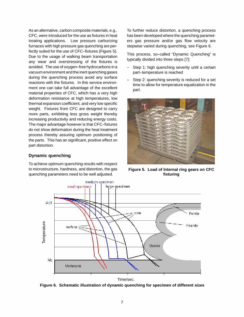
As an alternative, carbon composite materials, e.g.,CFC, were introduced for the use as fixtures in heattreating applications. Low pressure carburizingfurnaces with high pressure gas quenching are per-fectly suited for the use of CFC--fixtures (Figure 5).Due to the usage of walking beam transportationany wear and overstressing of the fixtures isavoided. The use of oxygen--free hydrocarbons in avacuum environment and the inert quenchinggasesduring the quenching process avoid any surfacereactions with the fixtures. In this service environ-ment one can take full advantage of the excellentmaterial properties of CFC, which has a very highdeformation resistance at high temperatures, lowthermal expansion coefficient, and very low specificweight. Fixtures from CFC are designed to carrymore parts, exhibiting less gross weight therebyincreasing productivity and reducing energy costs.The major advantage however is that CFC--fixturesdo not show deformation during the heat treatmentprocess thereby assuring optimum positioning ofthe parts. This has an significant, positive effect onpart distortion.
Dynamic quenching
To achieve optimum quenching results with respectto microstructure, hardness, and distortion, the gasquenching parameters need to be well adjusted.
To further reduce distortion, a quenching processhas been developed where the quenching paramet-ers gas pressure and/or gas flow velocity arestepwise varied during quenching, see Figure 6.
This process, so--called “Dynamic Quenching” istypically divided into three steps [7]:
-- Step 1: high quenching severity until a certainpart--temperature is reached
-- Step 2: quenching severity is reduced for a settime to allow for temperature equalization in thepart.
Figure 5. Load of Internal ring gears on CFCfixturing
Time/sec.
Tem
pera
ture
Figure 6. Schematic illustration of dynamic quenching for specimen of different sizes
8
-- Step 3: quenching severity is increased againuntil the end of the quenching process. Thecontrol system in the quenching chamber allowsto control the different quenching steps of“Dynamic Quenching” in a very accurate waywith a good reproducibility. Optimum results areachieved when using helium. The light quench-ing gas helium can be decelerated andaccelerated very precisely for optimumdistortion control.
Distortion study
An intensive process optimization program wasstarted before the start of production of the 6--speedautomatic transmission. The specific challengewas to optimize distortion control of the Internal ringgears. The goal was to eliminate hard machiningcompletely on these components thus simplifyingthe process chain as postulated in Figure 1.Furnace supplier and transmission manufacturerworked in close cooperation and successfullyimplemented a serial process duly for the start ofproduction in 6/2006. The process consists of LPCusing acetylene as carburizing source and HPGQusing helium as quench medium. Prior to carburiz-ing, the parts are heated under an atmosphere of1,2 bar nitrogen. This “convective heating” isapplied to achieve uniform temperature distributioninside the load while heating up. Once thecarburizing temperature is reached, the pressure islowered to a few millibars and the carburizing is initi-ated. The application of HPGQ with DynamicQuenching and the use of CFC--fixtures madesubsequent machining--operations unnecessary.The findings were published by the authors of thispaper in 2006. [8]
Initially all Internal ring gears from each load werechecked for excessive distortion with a so called“roll checker”. A “roll checker” is an automatedmeasurement system utilizing a rolling master heldby a pivoting yoke. The yoke enables the roll masterspindle to move in the lead and taper directions asthe rolling master rotates in tight mesh with the testcomponent. Separate transducers located in thegimble head monitor lead and taper travel.
To become more cost--efficient, the transmissionmanufacturer wanted to abandon this one hundredpercent “roll checker” inspection of all parts andchange to a spotwise control of distortion. The goalwas to inspect only two gears per load. Therefore itwas necessary to further reduce the amount ofdistortion and the quenching process was optimized
again in 8/2008. Distortion studies were performedaccordingly on the three Internal gears (Reaction--Output-- and Input--Internal gears). Data from thesestudies will be presented in the following andcompared with the earlier findings of the authorsfrom 2006.
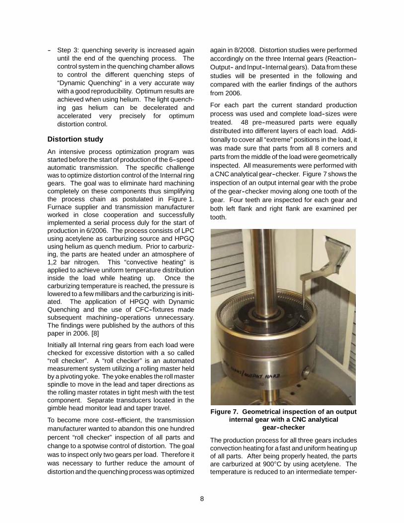
For each part the current standard productionprocess was used and complete load--sizes weretreated. 48 pre--measured parts were equallydistributed into different layers of each load. Addi-tionally to cover all “extreme” positions in the load, itwas made sure that parts from all 8 corners andparts from the middle of the load were geometricallyinspected. All measurements were performed witha CNC analytical gear--checker. Figure 7 shows theinspection of an output internal gear with the probeof the gear--checker moving along one tooth of thegear. Four teeth are inspected for each gear andboth left flank and right flank are examined pertooth.
Figure 7. Geometrical inspection of an outputinternal gear with a CNC analytical
gear--checker
The production process for all three gears includesconvection heating for a fast and uniform heating upof all parts. After being properly heated, the partsare carburized at 900C by using acetylene. Thetemperature is reduced to an intermediate temper-
9
ature and then the parts are quenched with heliumusing an optimized dynamic quenching process.
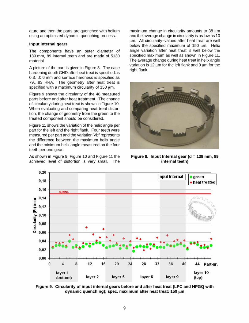
Input internal gears
The components have an outer diameter of139 mm, 89 internal teeth and are made of 5130material.
A picture of the part is given in Figure 8. The casehardening depth CHD after heat treat is specified as0,3…0,6 mm and surface hardness is specified as79…83 HRA. The geometry after heat treat isspecified with a maximum circularity of 150 mm.
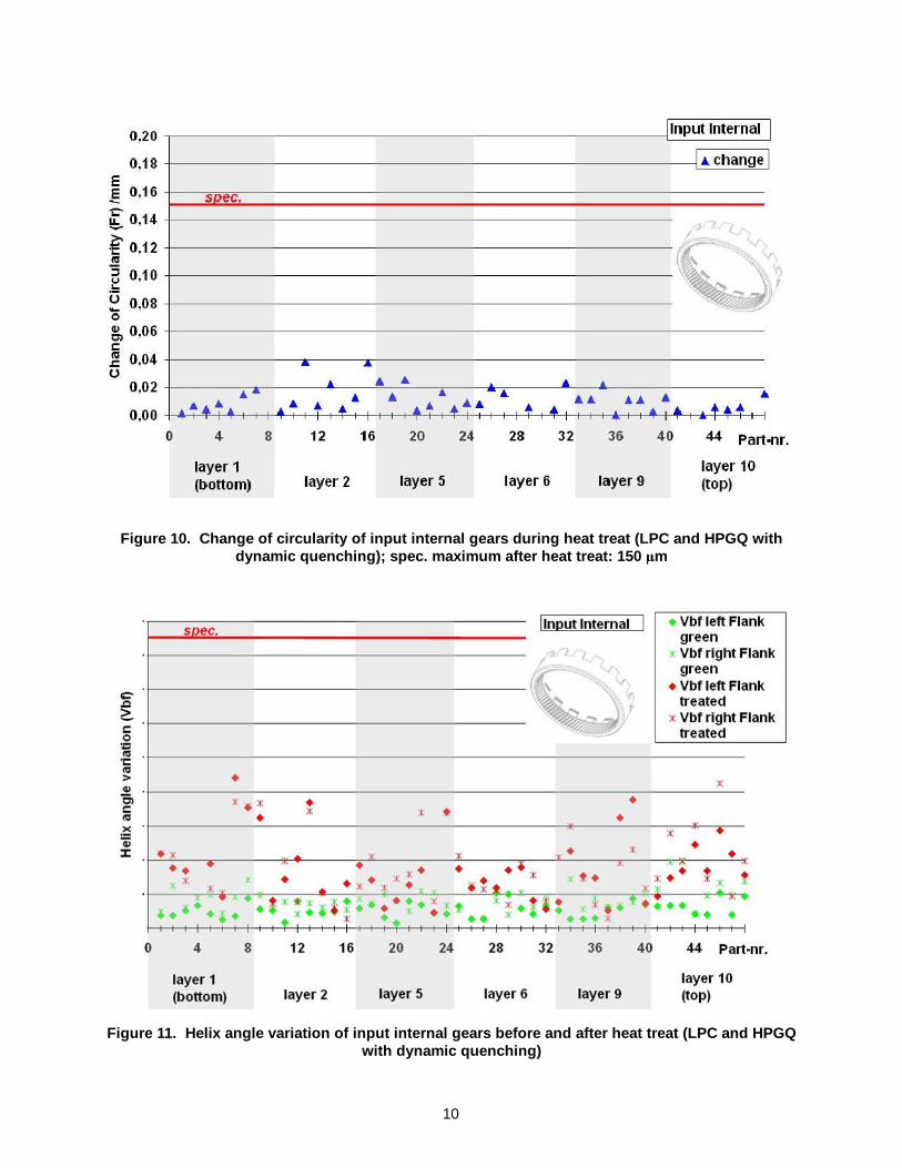
Figure 9 shows the circularity of the 48 measuredparts before and after heat treatment. The changeof circularity during heat treat is shown in Figure 10.When evaluating and comparing heat treat distor-tion, the change of geometry from the green to thetreated component should be considered.
Figure 11 shows the variation of the helix angle perpart for the left and the right flank. Four teeth weremeasured per part and the variation Vbf representsthe difference between the maximum helix angleand the minimum helix angle measured on the fourteeth per one gear.
As shown in Figure 9, Figure 10 and Figure 11 theachieved level of distortion is very small. The
maximum change in circularity amounts to 38 mmand the average change in circularity is as low as 10mm. All circularity--values after heat treat are wellbelow the specified maximum of 150 mm. Helixangle variation after heat treat is well below thespecified maximum as well as shown in Figure 11.The average change during heat treat in helix anglevariation is 12 mm for the left flank and 9 mm for theright flank.
Figure 8. Input Internal gear (d = 139 mm, 89internal teeth)
Figure 9. Circularity of input internal gears before and after heat treat (LPC and HPGQ withdynamic quenching); spec. maximum after heat treat: 150 mm
10
Figure 10. Change of circularity of input internal gears during heat treat (LPC and HPGQ withdynamic quenching); spec. maximum after heat treat: 150 mm
Figure 11. Helix angle variation of input internal gears before and after heat treat (LPC and HPGQwith dynamic quenching)
11
Reaction internal gears
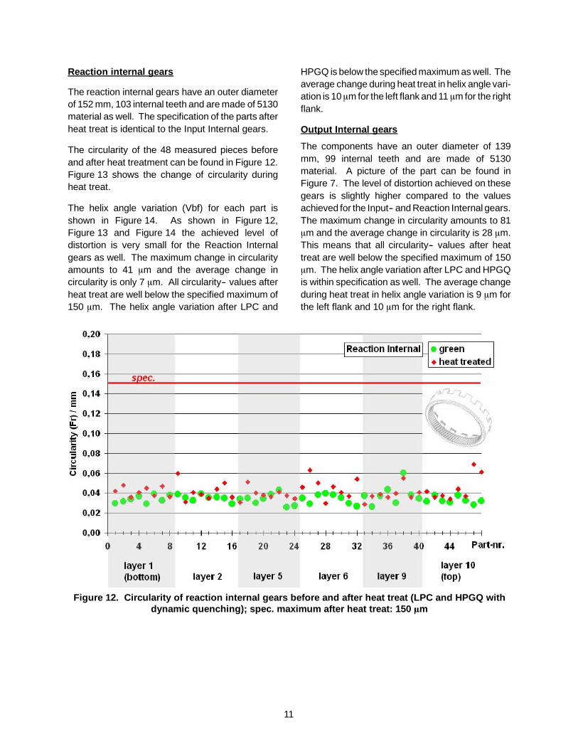
The reaction internal gears have an outer diameterof 152 mm, 103 internal teeth and are made of 5130material as well. The specification of the parts afterheat treat is identical to the Input Internal gears.
The circularity of the 48 measured pieces beforeand after heat treatment can be found in Figure 12.Figure 13 shows the change of circularity duringheat treat.
The helix angle variation (Vbf) for each part isshown in Figure 14. As shown in Figure 12,Figure 13 and Figure 14 the achieved level ofdistortion is very small for the Reaction Internalgears as well. The maximum change in circularityamounts to 41 mm and the average change incircularity is only 7 mm. All circularity-- values afterheat treat are well below the specified maximum of150 mm. The helix angle variation after LPC and
HPGQ is below the specified maximum as well. Theaverage change during heat treat in helix angle vari-ation is 10mm for the left flank and 11 mm for the rightflank.
Output Internal gears
The components have an outer diameter of 139mm, 99 internal teeth and are made of 5130material. A picture of the part can be found inFigure 7. The level of distortion achieved on thesegears is slightly higher compared to the valuesachieved for the Input-- and Reaction Internal gears.The maximum change in circularity amounts to 81mm and the average change in circularity is 28 mm.This means that all circularity-- values after heattreat are well below the specified maximum of 150mm. The helix angle variation after LPC and HPGQis within specification as well. The average changeduring heat treat in helix angle variation is 9 mm forthe left flank and 10 mm for the right flank.
Figure 12. Circularity of reaction internal gears before and after heat treat (LPC and HPGQ withdynamic quenching); spec. maximum after heat treat: 150 mm

12
Figure 13. Change of circularity of reaction internal gears during heat treat (LPC and HPGQ withdynamic quenching); spec. maximum after heat treat: 150 mm
Figure 14. Helix angle variation of reaction Internal gears before and after heat treat (LPC andHPGQ with dynamic quenching)
13
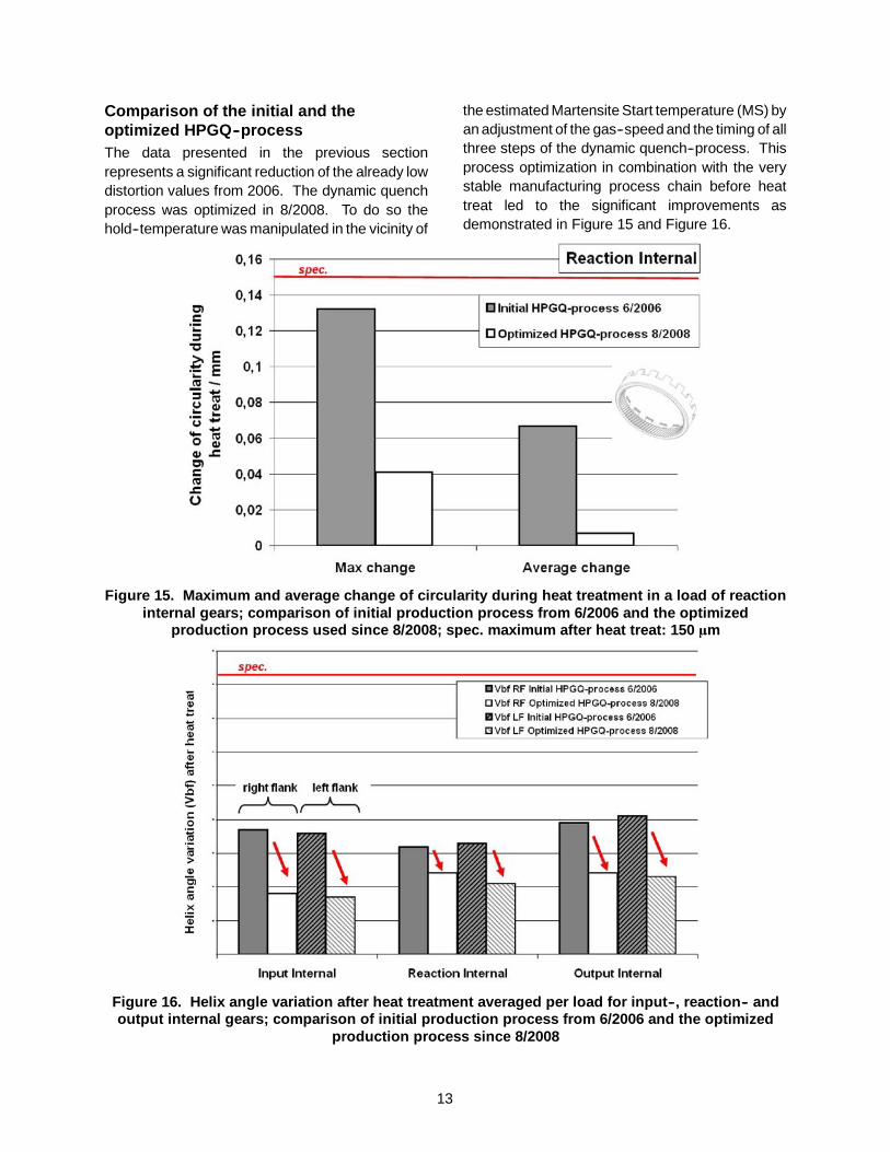
Comparison of the initial and theoptimized HPGQ--processThe data presented in the previous sectionrepresents a significant reduction of the already lowdistortion values from 2006. The dynamic quenchprocess was optimized in 8/2008. To do so thehold--temperature was manipulated in the vicinity of
the estimated Martensite Start temperature (MS) byan adjustment of the gas--speed and the timing of allthree steps of the dynamic quench--process. Thisprocess optimization in combination with the verystable manufacturing process chain before heattreat led to the significant improvements asdemonstrated in Figure 15 and Figure 16.
Figure 15. Maximum and average change of circularity during heat treatment in a load of reactioninternal gears; comparison of initial production process from 6/2006 and the optimized
production process used since 8/2008; spec. maximum after heat treat: 150 mm
Figure 16. Helix angle variation after heat treatment averaged per load for input--, reaction-- andoutput internal gears; comparison of initial production process from 6/2006 and the optimized
production process since 8/2008
14
Figure 15 shows a comparison of two loads ofreaction internal gears. One load was treated in2006 with the initial HPGQ--process [8] and theother load was treated with the optimized HPGQ--process. The average change of circularity duringheat treat was reduced from 67 to 7 mm and thebiggest change of circularity inside the load wasreduced from 132 to 41 mm.
The helix angle variations after heat treat from sixdifferent loads are presented in Figure 16. One loadof each type of Internal gears was treated in 2006with the initial HPGQ--process and one load of eachtype was treated with the optimized HPGQ--process. Both for the right flanks as for the leftflanks the helix angle variations were significantlyreduced.
As discussed earlier in this paper, the residualstresses inside the components can contribute todistortion. This means that the level of residualstress inside these gears before heat treat must bevery low to allow such a low level of distortion afterheat treatment.
Distortion monitoring in serial production
Serial production of the transmission started in
6/2006. Initially all Internal ring gears from eachload were checked for excessive distortion with a socalled “Roll checker”. As distortion proved to bevery consistent after introduction of the optimizedprocess in 8/2008, the transmission manufacturerdecided to abandon the one hundred percentinspection of all parts. Since 10/2008 only twogears per load are being measured with a CNCanalytical gear checker. One part from the topcorner and one part from the bottom middle are be-ing inspected in each load. These two positionswere chosen to cover the “extreme” positions in theload.
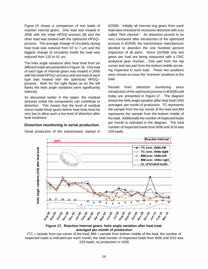
Results from distortion monitoring sinceintroduction of the optimized process in 8/2008 untiltoday are presented in Figure 17. The diagramshows the helix angle variation after heat treat (Vbf)averaged per month of production. TC representsthe sample from the top corner of the load and BMrepresents the sample from the bottom middle ofthe load. Additionally the number of inspected loadsper month is indicated in the diagram. The totalnumber of inspected loads from 8/08 until 3/10 was229 loads.
Figure 17. Reaction Internal gears: helix angle variation after heat treataveraged per month of production
(TC = sample from top corner of the load; BM = sample from bottom middle of the load; the number ofinspected loads is indicated per each month; the total number of inspected loads from 8/08 until 3/10 was
229 loads; no production in 1/09)
15
Figure 17 demonstrates that the distortion--valuesin serial production are very stable. This wasachieved with the help of the optimized LPC & HP-GQ process in combination with the stablemanufacturing process chain of the components.
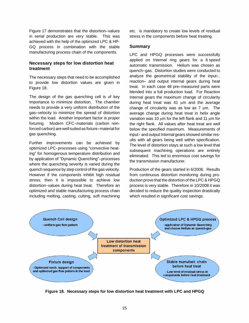
Necessary steps for low distortion heattreatment
The necessary steps that need to be accomplishedto provide low distortion values are given inFigure 18.
The design of the gas quenching cell is of keyimportance to minimize distortion. The chamberneeds to provide a very uniform distribution of thegas--velocity to minimize the spread of distortionwithin the load. Another important factor is properfixturing. Modern CFC--materials (carbon rein-forced carbon) are well suited as fixture--material forgas quenching.
Further improvements can be achieved byoptimized LPC--processes using “convective heat-ing” for homogenous temperature distribution andby application of “Dynamic Quenching”--processeswhere the quenching severity is varied during thequench sequence by step control of the gas velocity.However if the components inhibit high residualstress, then it is impossible to achieve lowdistortion--values during heat treat. Therefore anoptimized and stable manufacturing process chainincluding melting, casting, cutting, soft machining
etc. is mandatory to create low levels of residualstress in the components before heat treating.
Summary
LPC and HPGQ processes were successfullyapplied on Internal ring gears for a 6 speedautomatic transmission. Helium was chosen asquench--gas. Distortion studies were conducted toanalyze the geometrical stability of the input--,reaction-- and output internal gears during heattreat. In each case 48 pre--measured parts wereblended into a full production load. For ReactionInternal gears the maximum change of circularityduring heat treat was 41 mm and the averagechange of circularity was as low as 7 mm. Theaverage change during heat treat in helix anglevariation was 10 mm for the left flank and 11 mm forthe right flank. All values after heat treat are wellbelow the specified maximum. Measurements ofinput-- and output Internal gears showed similar res-ults with all gears being well within specification.The level of distortion stays at such a low level thatsubsequent machining operations are entirelyeliminated. This led to enormous cost savings forthe transmission manufacturer.
Production of the gears started in 6/2006. Resultsfrom continuous distortion monitoring during pro-duction prove that the distortion of the LPC & HPGQprocess is very stable. Therefore in 10/2008 it wasdecided to reduce the quality inspection drasticallywhich resulted in significant cost savings.
Figure 18. Necessary steps for low distortion heat treatment with LPC and HPGQ

16
References
1. Heeß, K.: Maß-- und Formänderungen infolgeWärmebehandlung von Stählen. ExpertVerlag. 3. neu bearbeitete Auflage (2007),ISBN--10: 3--8169--2678--9.
2. Walton, H.: Dimensional changes duringhardening and tempering of through--hardenedbearing steels. Quenching and Distortioncontrol (Conference Proceedings), ASMInternational, 1992, S. 265--273.
3. Stich; Tensi. In: HTM 50 (1995).
4. Löser, K.; Heuer, V.; Schmitt, G.: Auswahlgeeigneter Abschreckparameter für die Gasab-schreckung von Bauteilen aus verschiedenenEinsatzstählen, In: HTM 60 (2005) -- 4, page248--254.
5. Heuer, V.; Löser, K.: Low pressure carburizingfor transmissions. In: Gear solutions July 2009.
6. Löser, K.; Stueber, G.; Welzig, G.; Heuer, V.:United States Patent No. US 6,913,449 B2“Apparatus for the treatment of metallic work-pieces with cooling gas”,July 5, 2005.
7. Heuer, V., Löser, K.: Entwicklung desdynamischen Abschreckens in Hochdruck--Gasabschreckanlagen, In: Mat.--wiss. u.Werkstofftech. 34 (2003), page 56--63.
8. Löser, K.; Heuer, V.; Faron D.R.: Distortion con-trol by Innovative Heat Treating Technologies inthe Automotive Industry. In: HTM 61 (2006)-- 6,page 326--329.
9. Altena H., Schrank, F. und Jasienski, W.: Re-duzierung der Formänderung von Getrieb-eteilen in Gasaufkohlungs--Durchstoßanlagendurch Hochdruck--Gasabschreckung. In: HTM60 (2005)1, S. 43--50.