Embed Size (px)
Citation preview
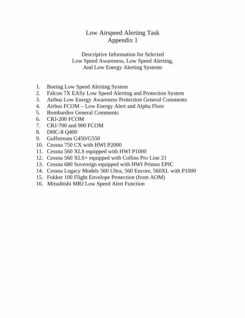
Low Airspeed Alerting Task Appendix 1
Descriptive Information for Selected
Low Speed Awareness, Low Speed Alerting, And Low Energy Alerting Systems
1. Boeing Low Speed Alerting System 2. Falcon 7X EASy Low Speed Alerting and Protection System 3. Airbus Low Energy Awareness Protection General Comments 4. Airbus FCOM – Low Energy Alert and Alpha Floor 5. Bombardier General Comments 6. CRJ-200 FCOM 7. CRJ-700 and 900 FCOM 8. DHC-8 Q400 9. Gulfstream G450/G550 10. Cessna 750 CX with HWI P2000 11. Cessna 560 XLS equipped with HWI P1000 12. Cessna 560 XLS+ equipped with Collins Pro Line 21 13. Cessna 680 Sovereign equipped with HWI Primus EPIC 14. Cessna Legacy Models 560 Ultra, 560 Encore, 560XL with P1000 15. Fokker 100 Flight Envelope Protection (from AOM) 16. Mitsubishi MRJ Low Speed Alert Function

Alert Trigger Point Visual Flight Deck Effects Aural Flight Deck Effects Inhibits
When the airspeed is 30% or more
in the amber band
‐ Amber band always present
‐ Speed Box steady amber
‐ EICAS Message‐AIRSPEED LOW
‐ Master Caution Light
Caution Beeper
TakeOff ‐ until in‐air AND [next flap retraction OR valid Vref].
Autoland ‐ < 200 ft; EICAS message is displayed but caution beeper
and master caution light are inhibited
THE EXPORT CONTROL VALUE OF THIS OBJECT IS ECCN VALUE 9E991 AND
HAS BEEN MARKED COM FOR PURPOSES OF EAR ACCESS CONTROL.
Boeing Basic Implementation of Low Speed Alert
Master caution light in
the glareshield Caution beeper
in speakers
A/T Min Speed
A/T Wake‐up (Min ‐ 8kts)
Autothrottle Minimum Speed Operations
Pitch trim inhibit; Column Force Rate Increase
Column Force Rapid Increase
FBWMin Speed and Stall Protection

Falcon 7X EASy Low speed awareness and protection system
High level description
The Falcon 7X contains a lot of features contributing to crew low speed awareness and low speed
protection. These features are mainly implemented within the following systems of the aircraft :
‐ Cockpit displays and alerting system
‐ Automatic Flight Control System (AFCS)
‐ Digital Flight Control System (DFCS)
‐
1‐ Cockpit displays and alerting system :
The following indications or alerts are implemented in the Falcon 7X EASy cockpit :
Low speed cues (LSC), displayed on the speed tape and composed of three elements :
o An amber band, indicating the area where airspeed is significantly (≈ 5kt) below the
minimum operational speeds
o An amber/black band, indicating the area where the Autopilot will be disengaged
o A red band, indicating the minimum speed which can be achieved with the sidestick on its
aft stop (corresponding to the maximum AOA allowed by the DFCS)
The low speed cues are computed based on aircraft weight, altitude, AOA, slats, flaps and airbrakes
configuration in order to provide relevant information to the crew in a large variety of conditions
(including FCS failures modes). In addition, some specific settings are used in icing conditions (anti‐
ice on)
Aural warning “Increase speed !”. This aural sounds as soon as airspeed penetrates the amber band
or the AFCS speed protection modes are activated (see below).
Stall warning : aural “Stall !”. The stall warning is triggered at an AOA that is slightly greater than
the maximum allowed by the DFCS. As a consequence, when stall warning sounds the speed is
always in the red band. Some specific settings are used in icing conditions (anti‐ice on)
Acceleration chevrons, displayed on the ADI relative to the speed vector
AOA path limit symbol, indicating the margin between current AOA and stall AOA when in low
speed conditions.
Speed trend, displayed on the speed tape
2‐ Automatic Flight Control System :
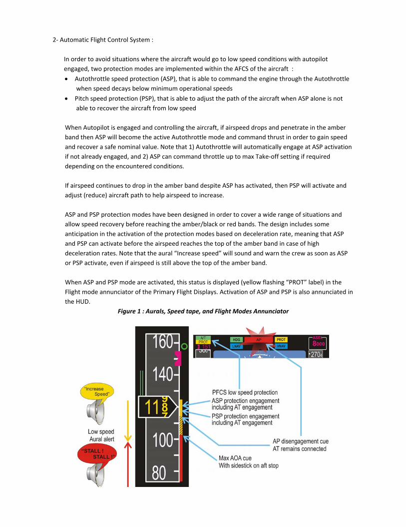
In order to avoid situations where the aircraft would go to low speed conditions with autopilot
engaged, two protection modes are implemented within the AFCS of the aircraft :
Autothrottle speed protection (ASP), that is able to command the engine through the Autothrottle
when speed decays below minimum operational speeds
Pitch speed protection (PSP), that is able to adjust the path of the aircraft when ASP alone is not
able to recover the aircraft from low speed
When Autopilot is engaged and controlling the aircraft, if airspeed drops and penetrate in the amber
band then ASP will become the active Autothrottle mode and command thrust in order to gain speed
and recover a safe nominal value. Note that 1) Autothrottle will automatically engage at ASP activation
if not already engaged, and 2) ASP can command throttle up to max Take‐off setting if required
depending on the encountered conditions.
If airspeed continues to drop in the amber band despite ASP has activated, then PSP will activate and
adjust (reduce) aircraft path to help airspeed to increase.
ASP and PSP protection modes have been designed in order to cover a wide range of situations and
allow speed recovery before reaching the amber/black or red bands. The design includes some
anticipation in the activation of the protection modes based on deceleration rate, meaning that ASP
and PSP can activate before the airspeed reaches the top of the amber band in case of high
deceleration rates. Note that the aural “Increase speed” will sound and warn the crew as soon as ASP
or PSP activate, even if airspeed is still above the top of the amber band.
When ASP and PSP mode are activated, this status is displayed (yellow flashing “PROT” label) in the
Flight mode annunciator of the Primary Flight Displays. Activation of ASP and PSP is also annunciated in
the HUD.
Figure 1 : Aurals, Speed tape, and Flight Modes Annunciator

3‐ Digital Flight Control System :
The F7X is fitted with a full authority Digital Flight Control System (DFCS) that has been specially
designed to contribute to crew low speed awareness and low speed protection.
DFCS offers a protection against excessive AOA, either when the pilot is controlling the aircraft
manually or when using the AFCS. The protection ensures that the aircraft will not go to stall. With
this kind of protection, the speed shall never drop down in the red band and stall warning shall
never be emitted (in nominal conditions).
The DFCS has also been designed in order to ensure that the pilot will immediately recognize that
aircraft is in low speed conditions, by restoring a strong static speed stability. This change in
aircraft behavior is progressive and can be perceived by the pilot as soon as the airspeed
penetrates the amber band, and is increasing as the speed drops down towards stall speed. If
airspeed drops down to the amber/black band, the autopilot is disengaged and the DFCS alone
performs low speed protection.

Low Energy awareness protection on Airbus Fly-By-Wire aircraft Compiled by N. Fabre-Raimbault & C. Thibaudat (Airbus) - FTHWG Sept, 16 2010
1) Design
A set of four protections is implemented on all Airbus FBW aircraft to protect the aircraft from low speed and low energy situations . They come in addition to the ‘High angle attack’ hard protection, protecting the aircraft from aerodynamic stall :
- The A/THR, if active in speed mode, prevents the speed to drop below VLS (Lowest Speed Selectable) regardless of target speed
- The Low-energy alert triggers a repetitive aural alert “Speed-Speed-Speed” when
the angle of attack becomes higher than an angle of attack threshold function of aircraft configuration, deceleration rate, flight path angle. It draws the crew attention to the speedscale and indicates the need to adjust thrust . In addition, the speedscale provides with a gradual overview of the different forthcoming critical speed threshold (from VLS in amber to Valphamax in plain red)
- The Alphafloor, an A/THR function , sends automatically TOGA thrust when the aircraft angle of attack exceeds the α-floor threshold in case the pilot has not properly adjusted the thrust. “A.FLOOR” is displayed (on FMA) and speedscale shows black-amber stripes. The goal is to avoid flying at low speed with low thrust.
- The Windshear aural warning triggers a message ‘Windshear Windshear Windshear’ when angle of attack becomes higher than an angle of attack threshold function of aircraft configuration and estimated longitudinal and vertical severity factors of encountered windshear.
The objectives of the low energy alert and of the alphafloor function are to protect the flight path angle by providing means to achieve a proper level of energy. The low energy alert will be triggered during deceleration before the activation of α-floor. (see FCOM pages attached for more information)
- High angle of attack protection Moreover, on all Airbus FBW aircraft, a high incidence protection protects the aircraft by limiting the angle of attack to a maximum achievable value α-max . This is a hard protection and cannot be overridden by the pilot (in normal laws). The high angle of attack protection is an aerodynamic protection. 2) Airbus experience Non overrideable high angle of attack protection is one of the main Electrical Flight Control System features of Airbus aircraft since the A320. It is available whatever the flight conditions. Low energy alert is available at low altitude only ( below 2000ft or 2500ft depending on the aircraft model) to cover the critical situation when the aircraft is close to the ground.

Because the aircraft remains safe even when the pilot pulls on the stick to the stop thanks to the high angle of attack protection, Airbus position is that no additional alerts about low speed/energy situations is needed at high altitude because large altitude loss due to stall cannot occur on Airbus Fly-By-Wire aircraft. Moreover, no additional stall warning or stick shaker is needed with this kind of protection. Stall warning is only re-introduced on airbus aircraft when the angle of attack protection is lost (loss of ‘normal laws’). At the beginning of A320 service experience, the setting of the α-floor function (automatic application of full thrust above a given angle of attack) was reviewed after the A320 Bangalore accident: the accident investigation revealed that the α-floor function came too late for avoiding the impact with ground. The α-floor setting was then decreased to the minimum setting compatible with FAA request and some phase advance terms with speed rate introduced. For remind, FAA considers the α-floor function as a stall indicator (equivalent to a stall warning for non-protected aircraft) and requires to demonstrate adequate bank manoeuvrability (25.143 compliance ) without α-floor triggering. This pushes to set α-floor triggering threshold to high incidence. The lack of static stability between VREF (or the lowest selectable speed called VLS at Airbus) and the starting point of the α-protection (i.e. α-prot) was also evoked as a possible contributing factor to the Bangalore accident. Then Airbus introduced a new function to compensate for this lack of static stability: the “low energy alert”, which is described above. It has been later enforced through a new special condition for Airbus aircraft. 3) Compliance requirements Low energy awareness is covered by EASA and FAA requirements through special conditions. Extract from Statement of Issue Low Energy Awareness: Static longitudinal stability provides awareness to the flight crew of a low energy state (low speed and thrust at low altitude). Recovery from a low energy slate may become hazardous when associated with a low altitude(1) and performance limiting conditions. These low energy situations must therefore be avoided, and pilots must be given adequate cues when approaching such situations. Background Low Energy Awareness: Past experience on airplanes fitted with a flight control system providing neutral longitudinal stability shows there is insufficient feedback cues to the pilot of excursion below normal operational speeds. The maximum angle of attack protection system limits the airplane angle of attack and prevents stall during normal operating speeds, but this system is not sufficient to prevent stall at low speed excursions below normal operational speeds. Until intervention, there are no stability cues since the aircraft remains trimmed. Additionally, feedback from the pitching moment due to thrust variation is reduced by the flight control laws. Recovery from a low speed excursion may become hazardous when the low speed situation is associated with a low altitude and with the engines at low thrust or with performance limiting conditions. Low energy awareness complies with the following requirements :

The airplane should provide adequate awareness cues to the pilot of a low energy (low speed/low thrust/ low height) state to ensure that the airplane retains sufficient energy to recover when flight control laws provide neutral longitudinal stability significantly below the normal operating speeds. This may be accomplished as follows: a) Adequate low speed/low thrust cues at low altitude may be provided by a strong positive static stability force gradient (1 pound per 6 knots applied through the sidestick), or b) The low energy awareness may be provided by an appropriate warning with the following characteristics:
(i) It should be unique, unambiguous, and unmistakable. (ii) It should be active at appropriate altitudes and in appropriate configurations (i.e., at low altitude, in the approach and landing configurations). (iii) It should be sufficiently timely to allow recovery to a stabilized flight condition inside the normal flight envelope while maintaining the desired flight path and without entering the flight controls angle-of-attack protection mode. (iv) It should not be triggered during normal operation(2) , including operation in moderate turbulence for recommended maneuvers at recommended speeds (v) It should not be cancelable by the pilot other than by achieving a higher energy state. (vi) There should be an adequate hierarchy among the various warnings so that the pilot is not confused and led to take inappropriate recovery action if multiple warnings occur.
c) Global energy awareness and non-nuisance(2) on low energy cues should be evaluated by simulator and flight tests in the whole take-off and landing altitude range for which certification is requested. This would include all relevant combinations of weight, center of gravity position, configuration, airbrakes position, and available thrust, including reduced and derated take-off thrust operations and engine failure cases. A sufficient number of tests should be conducted, allowing the level of energy awareness and the effects of energy management errors to be assessed. Note( 1) : it is recognized that the critical situation to cover is low altitude in case of ground proximity Note (2):FAA interpret non-nuisance requirement in showing compliance to 25.143(h) bank angle maneurabilities free of alphafloor


General comments/Clarifications on CRJ200/;700/900 low speed awareness philosophy.
In addition to stall warning provided by stick shakers and stall prevention/identification provided by stick pusher, the functionality of the Low Speed Cue (checkerboard, displayed on all aircraft) and Low Speed Awareness Indicator (“green line”) are described in the FCOMs of the respective aircraft. The Low Speed Awareness Indicator is, described only in the FAA versions of the FCOM.
The following compares the descriptions in the two FCOMs for CRJ-200 and CRJ-900 (CRJ-700 and CRJ-900 can be considered identical for the purposes of this discussion).
CRJ-200 FCOM Vol.1 12-30-14:
I. Low Speed Cue
The low speed cue provides an indication of the speed margin to stick pusher during normal low speed maneuvers and approaches to stall. The top of the low speed cue corresponds to 1.05 times the computed stick pusher speed.
NOTE
The minimum speed margin between shaker and pusher is 5%. This is larger in some parts of the flight envelope, particularly higher altitudes where factors other than landing field performance are the prime consideration. Therefore, the stick shaker speeds will be equal to or above the low speed cue. Respect the stick shaker warning to ensure adequate margin to full stall
A green line is displayed on the PFD speed tape that is 1.26 times the computed stick pusher speed. The green line is calculated through flap angle, AOA and Mach. The green line is not intended to be used as a substitute for reference speeds, or as a minimum maneuvering speed. It is intended to function as a low speed awareness indicator for the flight crew to inform them that they have a 26% margin above the stick pusher activation speed that is based on the current flight conditions.
CRJ-900 FCOM Vol.1 34-13-12:
(4). Low Speed Cue
The low speed cue provides an indication of the speed margin to stick shaker during normal low speed maneuvers and approaches to stall. The top of the low speed cue corresponds to the onset of the stick shaker.
NOTE
A high pitch rate at low airspeed may cause the stick shaker airspeed to be higher than that indicated at the top of the low speed cue. Respect the stick shaker warning to ensure adequate margin to full stall.
A green line displayed on the PFD speed tape that is 1.25 times the stall warning speed marked at the top of the red--black checkerboard on the speed tape. The green line is calculated through flap angle, AOA and Mach. The green line is not intended to be used as a substitute for reference speeds, or as a minimum maneuvering speed. It is intended to function as a low speed awareness indicator for the flight crew to inform them that they have a 25% margin above the stick shaker activation speed that is based on the current flight conditions.
There is a difference in the mechanism used to calculate the low speed cue between the two aircraft; although the intent is to provide a comparable end result for the pilot – namely awareness when the aircraft speed is closer than is desirable to stall warning – the text above largely differs in response to this detail of implementation.
For both aircraft the means used to calculate the speed for the display of the Low Speed Cue and the Green Band is called “normalized angle of attack”. The general formula that is used to calculate the value of the speed cues follows:
VSpeed Cue = K x VIAS x N where: K = Constant (dependent on speed cue and aircraft type) VIAS = Current airspeed N = Normalized AOA (dependent on aircraft type) The computation for the above formula is performed in the PFD using values of K and VIAS provided by the on-side ADC and a value for N provided by the on-side Stall Protection Computer (SPC) channel. The value off K is dependent upon both the specific aircraft type and also the parameter which is being calculated (Low Speed Cue or Green Line)
The normalized AOA on the CRJ-200 is calculated with reference to the pusher firing angles and therefore the speed cue computations provide an indication of speed margin above pusher activation. The normalized AOA on the CRJ-700 / 900 is calculated with reference to the shaker firing angles and therefore the speed cue computations provide an indication of speed margin above shaker activation. The reason for these differences in implementation goes to the difference in the settings for shaker and pusher firing angles between the two aircraft types. For the CRJ-200 the stick pusher is always set to fire prior to the natural stall of the aircraft (and is thus often referred to as a “pre-stall pusher”). For the CRJ-900 (and indeed also the CRJ-700) the pusher actually fires after the point of aerodynamic stall for all slats OUT configurations. This is therefore called a “post-stall pusher”. The normalized AOA calculation inherently assumes that the aircraft lift-curve slope is linear throughout the range of calculation. As the lift-curve becomes non-linear near the natural aerodynamic stall, the upper limit of the normalized AOA range must therefore be below the point of stall.


DHC-8 Q400 Low Speed Cue Information
1) The Q400 does not have a low speed alerting or low energy alerting system in the same sense that Boeing and Airbus do provide above the stall warning speed. However, because the Q400 is propeller-driven, there is the impact of powered lift. 2) The low-speed cue (barber pole) on the Q400 gives the margin to the estimated stall warning speed in the idle power configuration. If the power setting is anything above idle (AEO or OEI), the barber pole will be higher than the actual stall warning speed thus providing some margin to stall warning. 3) The low speed cue is a function of idle power stall warning angle-of-attack. There is a basic stall warning AOA that is modified by slightly by flap position, Mach and icing condition. Landing gear position is not considered. Gross weight and cg affect aircraft AOA which will in turn affect the low speed cue. 4) Because the low speed cue is based primarily on AOA, load factor is automatically accounted for and the low speed cue increases in maneuvering flight (positive g). 5) Stall warning is not modified by deceleration (or alpha dot) and thus the low speed cue is also unaffected. However, there is an airspeed trend vector that provides a 10 sec look-ahead for airspeed which will give the crew an indication of how rapidly they are approaching the low speed cue. 6) Regarding icing conditions, stall warning is manually advanced by the pilot selecting an "INCR REF SPD" switch. The stick pusher is not advanced. This in turn increases the low speed cue. Reference speeds are increased in the AFM when the INCR REF SPD switch is selected. 7) The ice protection system is manually selected by the pilot based on either a visual assessment by the crew or an ice detector alert. 8) The low speed cue is active any time that the airplane is airborne. There are no special considerations for any phase of flight or for manual vs. autoflight. 9) Turbulence nuisance effects are minimized through filtering of the low speed cue and stall warning. I hope that this helps in the upcoming discussions. For the Global Express, the information is very similar to that provided for the CRJ. Allan Paige

Gulfstream G450/G550 Low Speed Awareness and Stall Protection System (submitted by S. Taylor and J. O’Meara)
The stall warning and protection system (SWPS) installed on the Gulfstream Model G450/G550 aircraft provides a two stage stall warning/protection. The first stage provides warning to the pilot that the aircraft is approaching a stall condition. This warning is given through a stick shaker motor and low speed awareness indication on the airspeed tape. The second stage or stall protection is a stick pusher actuator that results in a pitch down force applied to the control column prior to aerodynamic stall. The stall warning function compares the current normalized AOA to an established normalized AOA threshold. The normalized AOA stick shaker threshold used is 0.85. Prior to stick shaker, a red low speed awareness (LSA) bar is located on the inside right edge of the airspeed tape (see Figure 1). It extends from the stick shaker speed to the bottom edge of the airspeed tape. This method of low speed awareness and pitch limit indication is the same for both the classic primary flight display (Figure 1) and the synthetic vision primary flight display (SV PFD) (Figure 2).
Figure 1. Classic G450/550 Primary Flight Display (PFD) with Low Speed Awareness Bar During Approach
An additional cue that is provided to alert the crew to an impending stick shaker is the pitch limit indicator, or PLI. The amber PLI consists of two horizontal lines with vertical slanting lines extending upward from the horizontal lines. The PLI is displayed when the normalized AOA is greater than 0.7, and moves vertically along the pitch ladder. The PLI is referenced to the airplane symbol or FPM (Flight Path Marker) depending on the symbology in use as selected by the pilot. The SV PFD provides additional speed cueing with the speed error tape off the left wing of the FPM. The length of the speed error tape represents the difference between the selected airspeed and the current airspeed, same as used on the HUD. The speed error tape rises or descends to a maximum length of approximately 0.63 inches at an airspeed differential of 20 kt/.04M. Downward movement of the speed error tape indicates current airspeed is less than the selected airspeed. Upward movement of the speed error tape indicates current airspeed is greater than the selected airspeed.
Low Speed Awareness Bar
(top of bar is stick shaker
speed)

Figure 2. SV PFD with Pitch Limit Indicator When the airplane deceleration rate as shown by the airspeed trend vector touches the top of the LSA tape, the IAS/mach digital display, airspeed rolling digits, and angle of attack readout will turn amber. When the FPM on the SV PFD (or any selected flight director airplane symbol on the classic PFD) touches the PLI, the stick shaker will activate indicating that the IAS is equal to low speed awareness speed. The IAS/mach digital display, airspeed rolling digits, and angle of attack readout will turn red. Continued deceleration of the airplane into the red zone of the LSA will eventually cause the stick pusher to activate. Examples of this are in Figure 3 and 4 below, which illustrates the changes in airspeed digits and AOA during an approach to stall.
Figure 3. G450/550 Classic Primary Flight Display Demonstrating Amber and Red Airspeed and AOA Limits During an Approach to Stall
Pitch Limit Indicator (PLI)
Displayed Prior to Stick Shaker
Speed Error Tape

Figure 4. G450/550 SV PFD Demonstrating Amber and Red Airspeed and AOA Limits During an Approach to Stall
Gulfstream classic aircraft do not have alpha-limiting via flight control laws as they are not fly-by-wire aircraft.

Cessna Model 750 CX equipped with Honeywell P2000
Low Airspeed Awareness Thermometer

Cessna Model 560XLS equipped with Honeywell Primus P1000 CDSR
Low Airspeed Awareness Thermometer
Airspeed Trend Vector
Green caret along the right outside scale identifies 1.3 Vstall
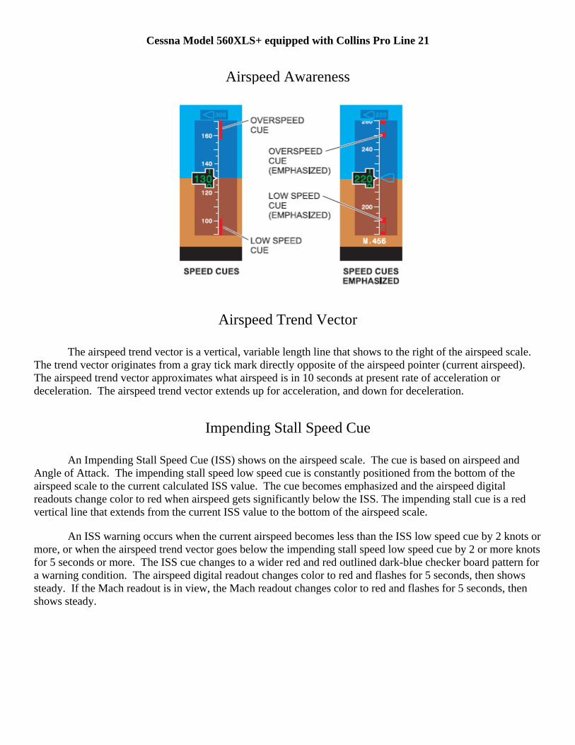
Cessna Model 560XLS+ equipped with Collins Pro Line 21
Airspeed Awareness
Airspeed Trend Vector
The airspeed trend vector is a vertical, variable length line that shows to the right of the airspeed scale. The trend vector originates from a gray tick mark directly opposite of the airspeed pointer (current airspeed). The airspeed trend vector approximates what airspeed is in 10 seconds at present rate of acceleration or deceleration. The airspeed trend vector extends up for acceleration, and down for deceleration.
Impending Stall Speed Cue
An Impending Stall Speed Cue (ISS) shows on the airspeed scale. The cue is based on airspeed and Angle of Attack. The impending stall speed low speed cue is constantly positioned from the bottom of the airspeed scale to the current calculated ISS value. The cue becomes emphasized and the airspeed digital readouts change color to red when airspeed gets significantly below the ISS. The impending stall cue is a red vertical line that extends from the current ISS value to the bottom of the airspeed scale.
An ISS warning occurs when the current airspeed becomes less than the ISS low speed cue by 2 knots or more, or when the airspeed trend vector goes below the impending stall speed low speed cue by 2 or more knots for 5 seconds or more. The ISS cue changes to a wider red and red outlined dark-blue checker board pattern for a warning condition. The airspeed digital readout changes color to red and flashes for 5 seconds, then shows steady. If the Mach readout is in view, the Mach readout changes color to red and flashes for 5 seconds, then shows steady.

Cessna Model 680 Sovereign equipped with Honeywell Primus EPIC
Low Airspeed Awareness Thermometer and Airspeed Trend Vector
Green caret along the right outside scale identifies 1.3 Vstall
Flap Deployment Speed Awareness
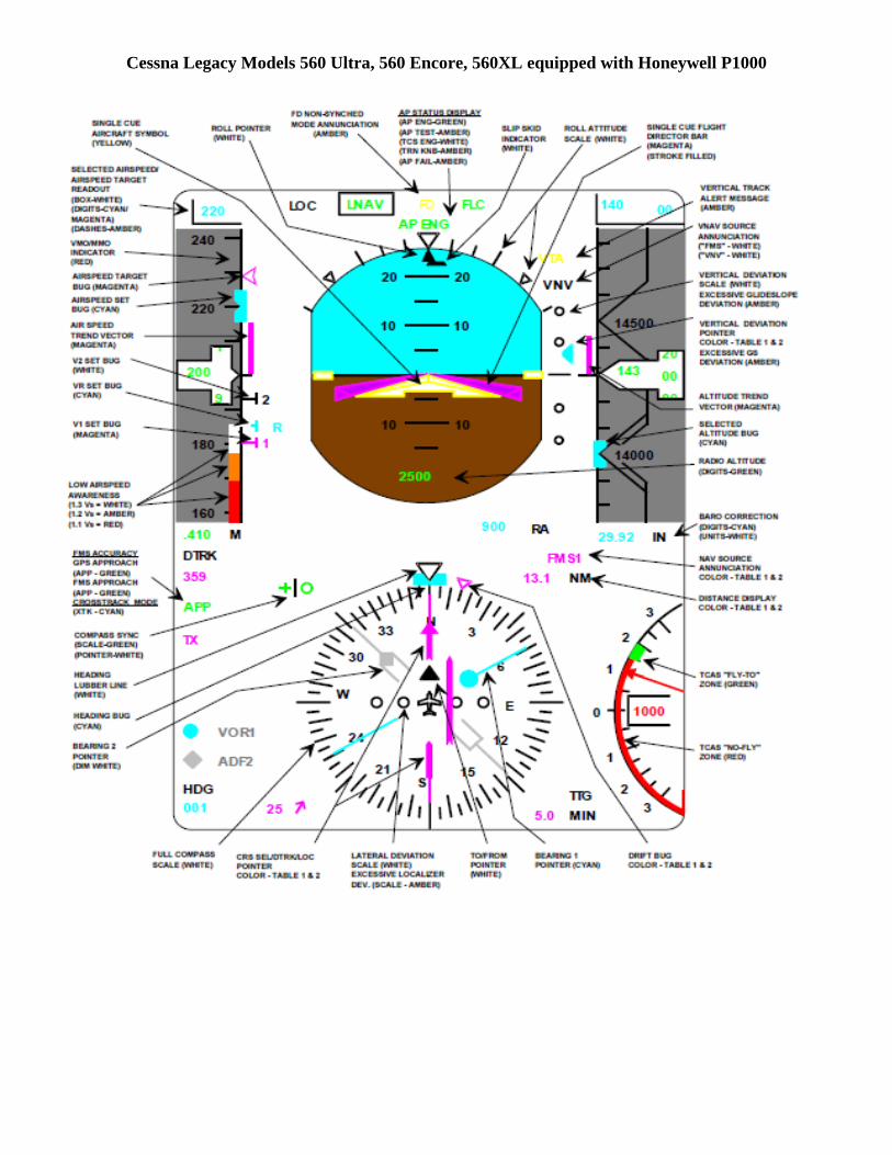
Cessna Legacy Models 560 Ultra, 560 Encore, 560XL equipped with Honeywell P1000
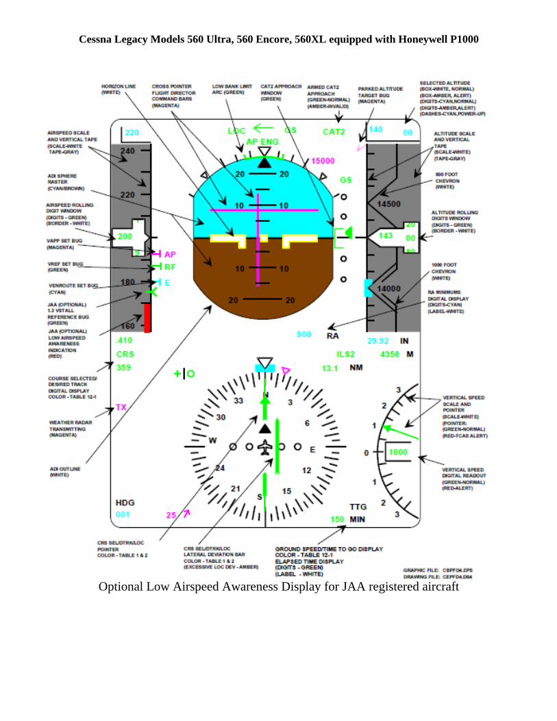
Cessna Legacy Models 560 Ultra, 560 Encore, 560XL equipped with Honeywell P1000
Optional Low Airspeed Awareness Display for JAA registered aircraft
PAGE 1
AFCAS flight envelope protection consists of:- Minimum speed protection i.e. speeds
below VMA, the minimum allowable flight
speed.- Maximum speed protection i.e. exceed-
ing VMO/MMO, VLE or VFE.
- Excessive vertical speed protection.- Flight path angle protection.- Automatic gust correction.- Altitude alerting.The FCC's calculate the reference speed fordisplay at the PFD speed scale. The speedsare VMA, VSS (stick shaker). VF (flap retrac-
tion) and green dot speed (VFTO, the final
take-off climb or max angle climb speed).
NOTE: If during flight in PROF conditionsoccur which activate any of the flightenvelope protection features, PROFwill disengage automatically. Fur-ther system behaviour is asdescribed for the applicable AFCASmode.
MINIMUM SPEED PROTECTION
Minimum speed protection consists of VMA
protection, Alpha (or angle of attack) modeand drift down control.VMA is displayed as the top of the amber strip
at the PFD speed scale after becoming air-borne.VMA depends on weight, flap setting, flight
phase and altitude.During take-off and go-around VMA is equal
to 1.20 VS. In all other flight phases VMA is
equal to 1.30 VS.
The transition from 1.20 VS to 1.30 VS occurs
20 sec. after LVLCH selection (or selection ofanother vertical mode) or PROF capture.To safeguard against a possible situationwhere VMA remains at 1.20 VS during
approach and landing, AFCAS contains sev-eral safety features which assure automatictransition in case LVLCH is not selected orPROF is not captured. In case of an enginefailure during take-off or go-around the tran-sition to 1.30 VS is postponed until after
thrust reduction from TOGA or FLEX thrustto MCT (or another thrust rating).To provide sufficient margin to the low speedbuffet at high altitude, VMA increases to
1.45 VS at 15 250 ft and increases linearly to
1.62 VS at FL 350.
VMA Protection
AFCAS does not accept speed selectionsbelow VMA i.e. if the pilot selects a speed
below VMA, the FMP speed window will dis-
play this speed but the blue speed select bug(VSEL) at the PFD speed scale will equal
VMA.
AFCAS will not guide or control to speedsbelow VMA because:
- When speed is controlled by elevator(IASE or ME at FMA) AFCAS provides AP
control and/or FD pitch commands to pre-vent deceleration below VMA.
- When speed is controlled by thrust (IAST
or MT at FMA) ATS adds thrust to prevent
deceleration below VMA.
NOTE: If during manual flight with ATSengaged in LVLCH decsent mode(thrust limit LL) the FD pitch com-mands are not followed, speed con-trol does not exist. If this is notnoticed e.g during visual flight andthe speed is allowed to drop below1.30 VS, AFCAS will change auto-
matically from LVLCH to V/S mode(speed controlled by thrust) andATS will subsequently control to theselected speed.
Alpha Mode
VMA protection is not always available or
adequate. Some conditions where VMA pro-
tection is not available are:- AP engaged in ALT hold or V/S climb,
ATS disengaged and idle thrust.- Manual flight with FD off and ATS disen-
gaged.- If during manual flight in LVLCH descent
the FD commands are not followed.In addition VMA protection may be not ade-
quate in conditions of strong turbulence orduring fast decelerations. In all these condi-tions the Alpha mode (or Alpha floor protec-tion) safeguards against too low speeds.
System behaviour upon Alpha mode activa-tion is as follows:- ATS engages automatically (provided the
AT p/b's at the FAC panel are not off), - the thrust limit changes to TOGA,- AFCAS will control the speed to VMA or
the selected speed, whichever is thehigher, by adding thrust and decreasingpitch when rated TOGA thrust is not suffi-cient to accelerate.
1.18.04
VERSION 11ISSUE 003
--------------------------------------------------------------------------------- AOM FOKKER 100 --------------------------------------------------------------------------------
AUTOMATIC FLIGHT CONTROL & AUGMENTATION SYSTEM
FLIGHT ENVELOPE PROTECTION
DESCRIPTION

1.18.04
VERSION 11
ISSUE 003
PAGE 2
--------------------------------------------------------------------------------- AOM FOKKER 100 ------------------------------------------------------------------------------
NOTE: The speed at which the Alpha modeactivates increases with increasingload factor.
Alpha mode activation depends on the cur-rent AFCAS mode and will occur: - in TO mode when the speed drops
approx. 5 kt below 1.20 Vs;
- in GA mode when the speed drops belowapprox. 1.20 Vs + 5 kt;
- in ALT hold, V/S, and APPR mode whenthe speed drops approx. 5 kt below1.30 Vs;
- if during manual flight in LVLCH climb theFD commands are not followed and thespeed drops below 1.30 Vs.
NOTE: AFCAS will generate an AFCASTARGET alert on MFDS when thespeed drops approx. 15 kt below theselected speed.
In addition Alpha mode activation will occur ifFPV is selected or during manual flight withFD off and the speed drops approx. 5 ktbelow 1.30 VS.
CAUTION:
WHEN ATS ENGAGES AS A RESULT OFALPHA MODE ACTIVATION WITH THEENGINES SPOOLED DOWN OR IN CASEOF A HIGH DECELERATION RATE, THESPEED MAY FALL WELL BELOW VMA
BEFORE THE AIRCRAFT STARTS TOACCELERATE.THE FORCE OVERRIDE SWITCHES AREDE-ACTIVATED DURING ALPHA MODEOPERATION AND IF, AT THIS MOMENT,THE PILOT ATTEMPTS TO MANUALLYADVANCE THE THRUST LEVERS TOSPEED UP ENGINE RESPONSE, HEEXPERIENCES HEAVY OVERRIDEFORCES WHICH MAY GIVE THE IMPRES-SION THAT THE THRUST LEVERS AREBLOCKED. ALTHOUGH NOT RECOM-MENDED, ATS CAN BE OVERRIDDEN BYHOLDING THE ATS DISCONNECT BUT-TONS DEPRESSED AND SIMULTA-NEOUSLY ADVANCING THE THRUSTLEVERS UNTIL THE SPEED IS ABOVEVMA AND THE ALPHA MODE IS DE-ACTI-
VATED.
Drift Down Control
See FLIGHT TECHNIQUES.
MAXIMUM SPEED PROTECTION
VMAX is calculated by the FCC's and is dis-
played at the PFD speed scale as the bottomof the red checker bar.
If the pilot selects a speed in excess of VMAX,
the IAS/M display at the FMP will show thisspeed but the blue VSEL bug will equalVMAX. AFCAS will prevent exceeding VMAX
by either thrust or elevator control.If VMAX is reached and ATS is not engaged,
ATS engages automatically and reducesthrust to prevent exceeding VMAX.
When climbing in IAS select or IAS hold,automatic transition to Mach select orMach hold occurs at M.76.When descending in Mach select or Machhold automatic transition to IAS select or IAShold occurs at approx 315 kt IAS.
EXCESSIVE VERTICAL SPEED PROTEC-
TION
AFCAS safe guards against too low or toohigh speeds resulting from excessive verticalspeed selection by automatic mode changefrom V/S to LVLCH as follows:
V/S Climb
If the combination of selected V/S and speedexceeds the aircraft performance ATS willfirst increase thrust to the maximum EPR forthe selected thrust rating.When this thrust is incapable of maintainingthe selected speed and vertical speed, thevertical speed will be maintained at the costof speed.When the speed falls approx 15 kt below theselected speed the crew is warned by anAFCAS TARGET alert at MFDS.If no corrective action is taken the aircraft willfurther decelerate.At 1.30 VS AFCAS reverts automatically from
V/S climb to LVLCH climb. The aircraft willaccelerate to and maintain the (pre) selectedspeed or VMA, whichever is higher and climb
to the FMP altitude.
V/S Descent
If a vertical speed is selected which will resultin exceeding the selected speed, ATS willreduce thrust until idle is reached. If the speed increases further to approx 15 ktabove the selected speed, AFCAS gener-ates an AFCAS TARGET alert at MFDS.When no corrective action is taken the air-craft will accelerate further.At VMAX AFCAS reverts automatically from
the V/S to LVLCH descent.The aircraft will decelerate to and maintainthe (pre)selected speed or VMAX, whichever
is lower and descend to the FMP altitude.
AUTOMATIC FLIGHT CONTROL & AUGMENTATION SYSTEM
FLIGHT ENVELOPE PROTECTION
DESCRIPTION

- 1 -NA222339A
MRJ design approachMRJ design approachon the Low Speed Alert functionon the Low Speed Alert function
September 30th, 2010

- 2 -NA222339A
MRJ Low Speed Alert MRJ Low Speed Alert
Normal Airspeed TapeNormal Airspeed Tape
IAS Trend Vector
Min Maneuvering Speed
VminMarker
IAS Readout
All information contained herein is under development. It is provided for informational purposes only and is subject to change.

- 3 -NA222339A
MRJ Low Speed Alert MRJ Low Speed Alert
Low Speed CautionLow Speed Caution
• Vmin is used to depict minimum speed indication. It is an AOA based indication presented on the speed tape that depicts maximum wing lift with FAA mandated safety margins.
• The low speed caution occurs when the IAS trend vector goes below Vminfor 5 seconds or more.
• The airspeed readout changes color (to yellow) when the low airspeed caution is activated
• The low speed Vmin marker will be emphasized
VminMarker
IAS Readout IAS Trend Vector
Min Maneuvering Speed
All information contained herein is under development. It is provided for informational purposes only and is subject to change.

- 4 -NA222339A
MRJ Low Speed Alert MRJ Low Speed Alert
Low Speed WarningLow Speed Warning
• The low speed warning occurs when the current IAS is < the top of the Vmin Marker.
• The airspeed readout changes color (to red) when the low airspeed warning is activated
• The low speed Vmin marker will be emphasized
Vmin Marker
IAS Readout IAS Trend Vector
Min Maneuvering Speed
All information contained herein is under development. It is provided for informational purposes only and is subject to change.