Embed Size (px)
Citation preview

LoopView User's Manual for Loop-AM 3440
LOOP TELECOMMUNICATION INTERNATIONAL, INC.
8F, NO. 8, HSIN-ANN ROAD
SCIENCE-BASED INDUSTRIAL PARK
HSINCHU, TAIWAN
Tel: +886-3-578-7696
Fax: +886-3-578-7695

© 2008 Loop Telecommunication International, Inc. All rights reserved. LoopView is a trade mark of Loop Telecommunication International, Inc.
07/2008 Version 19

i
TABLE OF CONTENTS
1 PRODUCT DESCRIPTION ........................................................................................................................ 1
1.1 LOOPVIEW MANAGER FEATURES ........................................................................................................... 1 1.2 APPLICATION SETUP DIAGRAMS ............................................................................................................. 2 1.3 OVERVIEW OF LOOPVIEW, CASTLE ROCK AND TCP/IP............................................................................ 3
1.2.1 Castle Rock SNMPc Product Options ......................................................................................... 3 1.2.1.1 SNMPc Enterprise Edition .................................................................................................... 3 1.2.1.2 SNMPc Remote Access Extension ...................................................................................... 3 1.2.1.3 SNMPc Workgroup Edition................................................................................................... 3
2 SOFTWARE INSTALLATION .................................................................................................................... 4
2.1 CASTLE ROCK SOFTWARE INSTALLATION................................................................................................ 4 2.1.1 Required Equipment .................................................................................................................... 4 2.1.2 Software Copy Protection ............................................................................................................ 4 2.1.3 Installing TCP/IP Software........................................................................................................... 4 2.1.4 Installing Castle Rock SNMPc Software...................................................................................... 4
2.2 LOOPVIEW SOFTWARE INSTALLATION..................................................................................................... 5 2.2.1 Step by Step Instructions ............................................................................................................. 4
2.2.1.1 Installing Loopview V3.08 Software...................................................................................... 4 2.2.1.2 Uninstalling Loopview V4.09 Software ................................................................................. 8
2.2.1.2.1 Automatic Uninstall............................................................................................................ 10 2.2.1.2.2 Custom Uninstall ............................................................................................................... 11 2.2.1.2.3 Repair ................................................................................................................................ 14
3 SNMPC AND LOOPVIEW SETUP........................................................................................................... 17
3.1 STARTING THE SERVER AND GETTING LOGGED ON TO SNMPC. ........................................................... 17 3.1.1 Using SNMPc Console Elements .............................................................................................. 17 3.1.2 SNMPc Console Button Commands.......................................................................................... 18 3.1.3 SNMPc Selection Tool ............................................................................................................... 18 3.1.4 SNMPc Event Log Tool.............................................................................................................. 19 3.1.5 Working with the SNMPc Map Database................................................................................... 19
3.1.5.1 Using the SNMPc Map Selection Tree............................................................................... 19 3.1.6 Table Display Elements ............................................................................................................. 20
3.2 STEP BY STEP SNMPC OBJECT SETUP................................................................................................ 20 3.2.1 Adding a New Object ................................................................................................................. 20 3.2.2 Setting Up the Map Object Properties ....................................................................................... 21 3.2.3 New Object Icon......................................................................................................................... 22 3.2.4 MIB Files Location ..................................................................................................................... 23 3.2.5 Adding the MIB File Database ................................................................................................... 24 3.2.6 Compiling MIB Files ................................................................................................................... 25
3.3 STEP BY STEP AM 3440 ALARM SETUP USING PRLVATE MIB ................................................................ 27 3.3.1 Mib Selection Tree ..................................................................................................................... 27 3.3.2 Using Private Menus.................................................................................................................. 27 3.3.3 Opening the Loop Telecom Subtree......................................................................................... 28
3.4 STEP BY STEP LOOPVIEW SETUP......................................................................................................... 30 3.4.1 LoopView Icon ........................................................................................................................... 30 3.4.2 Setting Up AM 3440 Alarms in Loopview .................................................................................. 32
3.4.2.1 Opening LoopView ............................................................................................................. 32 3.4.2.2 Opening the Private Subtree .............................................................................................. 32
3.5 REDUNDANCY FUNCTION SETUP........................................................................................................... 35 3.5.1 SNMP Setup .............................................................................................................................. 35
4 OPERATION ............................................................................................................................................ 38
4.1 LOGIN SECURITY ................................................................................................................................. 38

ii
4.2 COMPILE MIB FILES ............................................................................................................................ 38 4.3 NETWORK MAP ................................................................................................................................... 38 4.4 OBJECT LAYOUT.................................................................................................................................. 40 4.5 THE FRAME MENU............................................................................................................................... 40 4.6 MONITORING NODES ........................................................................................................................... 40 4.7 THE EVENT LOG.................................................................................................................................. 41
5 GRAPHIC DEVICE WINDOWS ............................................................................................................... 42
5.1 TIME OUT CONFIGURATION .................................................................................................................. 42
6 LOOP-AM 3440........................................................................................................................................ 44
6.1 CONTROLLER ...................................................................................................................................... 44 6.1.1 Command Control...................................................................................................................... 44
6.2 ALARM ................................................................................................................................................ 45 6.3 MAPPING ............................................................................................................................................ 45 6.4 PROTECTION ....................................................................................................................................... 46
7 PLUG-IN CARDS ..................................................................................................................................... 47
7.1 ATM/FR CARD ................................................................................................................................... 47 7.1.1 ATM/FR System Info.................................................................................................................. 47 7.1.2 ATM/FR Control ......................................................................................................................... 48 7.1.3 ATM/FR Channel Map .............................................................................................................. 48 7.1.4 ATM/FR E1 Info.(I)..................................................................................................................... 49
7.2 DTE CARD.......................................................................................................................................... 50 7.2.1 Control........................................................................................................................................ 50 7.2.2 Alarm.......................................................................................................................................... 50 7.2.3 Diagnostic .................................................................................................................................. 50
7.3 6-PORT DTU CARD............................................................................................................................. 51 7.3.1 Control........................................................................................................................................ 51 7.3.2 Mapping ..................................................................................................................................... 51 7.3.3 Local Performance..................................................................................................................... 51
7.4 10-PORT DTU CARD........................................................................................................................... 52 7.4.1 Control........................................................................................................................................ 52 7.4.2 Mapping ..................................................................................................................................... 52 7.4.3 Local Performance..................................................................................................................... 53 7.4.4 Router Card ............................................................................................................................... 53
7.5 4-PORT G.SHDSL CARD....................................................................................................................... 54 7.5.1 Control(C)................................................................................................................................... 54
7.5.1.1 G.shdsl System Table(M) ................................................................................................... 55 7.5.1.2 G.shdsl System Setup(S) ................................................................................................... 55 7.5.1.3 List Line Config.(L).............................................................................................................. 55 7.5.1.4 Line Config. Setup(G) ......................................................................................................... 55 7.5.1.5 List AI Config(A).................................................................................................................. 56 7.5.1.6 AI Config. Setup(T) ............................................................................................................. 56 7.5.1.7 LineDiag. Control(D) ........................................................................................................... 56 7.5.1.8 LoopBack Setting(B)........................................................................................................... 57 7.5.1.9 List FractionalTable(F)........................................................................................................ 57 7.5.1.10 List Status Config. Table(G) ............................................................................................... 57 7.5.1.11 Information Table(I) ............................................................................................................ 58 7.5.1.12 Command Control Table(P)................................................................................................ 58 7.5.1.13 Command Control Setupl(H) .............................................................................................. 58 7.5.1.14 System Info. Table(E) ......................................................................................................... 58 7.5.1.15 Advance System Table(V).................................................................................................. 59 7.5.1.16 Advance System Setup(N) ................................................................................................. 59
7.5.2 LocalPerf(P) ............................................................................................................................... 59 7.5.2.1 Current Perf.(R) .................................................................................................................. 60 7.5.2.2 Total Perf.(T)....................................................................................................................... 60 7.5.2.3 Interval Perf.(I) .................................................................................................................... 60

iii
7.5.3 Alarm (L) .................................................................................................................................... 61 7.5.3.1 Alarm Queue(Q) ................................................................................................................. 61 7.5.3.2 List Alarm Status(L) ............................................................................................................ 61 7.5.3.3 Alarm Status Setup(S) ........................................................................................................ 61
7.5.4 Mapping(M)................................................................................................................................ 62 7.5.4.1 Current Slot TSI Map(R) ..................................................................................................... 62
7.6 E1 CARD ............................................................................................................................................ 63 7.6.1 Local Control(C)......................................................................................................................... 63 7.6.2 Local Performance..................................................................................................................... 63
7.6.2.1 User Performance............................................................................................................... 64 7.6.2.2 Line Performance ............................................................................................................... 64
7.6.3 Local Alarm ................................................................................................................................ 64 7.6.4 Mapping ..................................................................................................................................... 65
7.7 QUAD E1 CARD................................................................................................................................... 66 7.7.1 Local Control .............................................................................................................................. 66 7.7.2 Local Performance..................................................................................................................... 66
7.7.2.1 User Performance............................................................................................................... 67 7.7.2.2 Line Performance ............................................................................................................... 67 7.7.2.3 Line Availability Perf. .......................................................................................................... 67
7.7.3 Local Alarm ................................................................................................................................ 68 7.7.4 Mapping ..................................................................................................................................... 68
7.8 E&M CARD ......................................................................................................................................... 69 7.8.1 E&M Card(D) ............................................................................................................................. 69
7.8.1.1 EM Control(C)..................................................................................................................... 69 7.8.1.2 EM Diagnostic(B)................................................................................................................ 69
7.9 FOM CARD......................................................................................................................................... 70 7.9.1 Remote Loop-0 9310 Unit Menu................................................................................................ 72
7.10 FXO CARD ......................................................................................................................................... 73 7.10.1 FXO Control(C) .......................................................................................................................... 73 7.10.2 FXO Command Control(M) ........................................................................................................ 73 7.10.3 FXO Diag.(B) ............................................................................................................................. 74
7.11 FXS CARD.......................................................................................................................................... 75 7.11.1 FXS Control(C) .......................................................................................................................... 75 7.11.2 FXS Command Control(M) ........................................................................................................ 75 7.11.3 FXS Diag.(B).............................................................................................................................. 76
7.12 MAG CARD......................................................................................................................................... 77 7.12.1 Mag Control(C) .......................................................................................................................... 77 7.12.2 Mag Command Control(M) ........................................................................................................ 77 7.12.3 Mag Diag(B) allows.................................................................................................................... 78
7.13 MDSL CARD....................................................................................................................................... 79 7.13.1 Control........................................................................................................................................ 79 7.13.2 Performance .............................................................................................................................. 79 7.13.3 Alarm.......................................................................................................................................... 80 7.13.4 Mapping ..................................................................................................................................... 80 7.13.5 Router Card ............................................................................................................................... 80
7.14 ROUTER CARD .................................................................................................................................... 81 7.14.1 RTR Control(C) ......................................................................................................................... 81 7.14.2 RTR Command Control(M) ....................................................................................................... 81
7.15 T1 CARD............................................................................................................................................. 82 7.15.1 Local Control(C)......................................................................................................................... 82 7.15.2 Local Perf.(P) ............................................................................................................................. 82 7.15.3 Local alarm(A)............................................................................................................................ 83 7.15.4 Mapping(M)................................................................................................................................ 83
7.16 X.50 CARD ......................................................................................................................................... 84 7.16.1 X.50 Control(C) .......................................................................................................................... 84 7.16.2 X.50 Alarm(A) ............................................................................................................................ 84 7.16.3 X.50 Diagnostic(D)..................................................................................................................... 84

iv
LIST OF FIGURES
Figure 1- 1 SNMP Management via Ethernet Port.....................................................................2 Figure 1- 2 Inband Management ................................................................................................2 Figure 4- 1 Navigation Tree....................................................................................................39 Figure 4- 2 Multiple network map views ..................................................................................39 Figure 4- 3 Frame windows menu ...........................................................................................40 Figure 4- 4 Event log ...............................................................................................................41
LIST OF TABLES
Table 1- 1 Castle Rock SNMPc Options ...................................................................................3 Table 3- 1 Console Functions Table........................................................................................18 Table 3- 2 Selection Tool Description Table ...........................................................................18 Table 4- 1 Login security .........................................................................................................38 Table 4- 2 Event types.............................................................................................................41

Chapter 1 Product Description
1
1 PRODUCT DESCRIPTION LoopView (V4.09) is a graphical management tool for the centralized management of Loop products that are connected via LAN networks, and by extension WAN networks.
LoopView (V4.09) runs on Windows 98 or Windows NT, 2000. It is based on Castle Rock SNMPc network management tools. LoopView uses SNMP protocol to monitor and manage Loop products.
1.1 LoopView Manager Features Loopview Manager features include the following:
Runs under Microsoft Windows 98 or Windows NT, 2000. Has the standard features of windows application programs.
Scaleable to 10,000 devices. Includes multi-level login security. Groups network elements into a hierarchical structure to represent cities, buildings, rooms. Etc. Supports multiple simultaneous views of map levels, or log files in real time. Has two methods to create a network map: manually creates nodes, or automatically discovers nodes. Starts graphic device display when you double click on a device node icon, which provides friendly
interface to inquire and configure Loop Telecommunication International Inc.'s products, including front panel, connectors, and LEDs.
Long term statistics polling.
Polls nodes at user-specified polling intervals. Displays node, port, and network status using different colors.
Graphs or lists node statistic counters in real time. Custom MIB Tables with Derived MIB Expressions. Supports a complete Applications Programming Interface using the WinSNMP DLL API and the
Windows Dynamic Data Exchange (DDE). Executes commands from user-defined menus to display tables, edit table entries, display real-time lists
or graphs, and start API programs. Scheduled WEB and Printed Trend Reports Prints map and log file reports. Automatically discovers all IP and IPX nodes and creates a network map. Automatic statistic baselines and threshold alarms. Supports SNMP Proxy agents using different community strings and custom polling variables. GUI Device support for dozens of vendors. Event forwarding email/pager notifications. Full RMON-I user interface application. Web access with a JAVA Console.

Chapter 1 Product Description
2
1.2 Application Setup Diagrams Figure 1-1, below, depicts SNMP management of a Loop product via the ethernet connection.
Figure 1- 1 SNMP Management via Ethernet Port
Figure 1-2, below, depicts Inband Management. Management of the Loop-AM 3440 can be done through, the console port, the optional SNMP port or through the optional Router card with Subnet management (SNMC). Using the Router card, management of a local as well as remote Loop products (up to 32 inband management capable devices per card) is possible.
Figure 1- 2 Inband Management
E1/ T1 E1/ T1 NETWORK
LAN
ManagementTerminal
64 K
Loop-AM 344064 K
Router E1/ T1
In-Band Insertion
HDLC Loop-AM 3440
Router HDLC
In-Band Extraction
64 K
EthernetPort
LAN
PC Network Management StationSNMP Manager
Loop-AM 3440

Chapter 1 Product Description
3
1.3 Overview of LoopView, Castle Rock and TCP/IP LoopView is a GUI (grapical user interface) program that is designed to be used in conjunction with Castle Rock SNMPc5 or later versions. This Castle Rock program comes in different formats, as explained below. You must pick the appropriate edition for your system reqirements when selecting Castle Rock SNMPc.. In order to use the Castle Rock SNMPc program your computer must have a Windows compliant TCP/IP stack like that included in Windows 95,98, NT and 2000.
1.2.1 Castle Rock SNMPc Product Options SNMPc 5.0 includes the three product options described below. Choose the option that best suits your system reqiremelnts.
1.2.1.1 SNMPc Enterprise Edition
This is the base system for a scalable multi-user environment. Enterprise Edition includes the SNMPc Server license, one Remote Console license, and one Remote Poller license. This system can be used simultaneously by one user at the server system and by another user at a Remote Console system. The Remote Poller can be used to extend the polling capabilities to a remote polling site.
1.2.1.2 SNMPc Remote Access Extension
This is a license only option for the Enterprise Edition. This option allows an unlimited number of Remote Console users and Remote Polling agents. It also provides JAVA Console support. When using this option, you must install the server under Windows NT or 2000 only..
1.2.1.3 SNMPc Workgroup Edition
This is a single user version for managing small to medium sized networks. The Workgroup Edition can be used on Windows 2000, NT, and 98 systems. All components run on a single system and support one user. The map database size is limited to 1000 objects. The Workgroup Edition does not include advanced reporting functions. The following table shows the differences between the three product options:
Table 1- 1 Castle Rock SNMPc Options

Chapter 2 Software Installation
4
2 SOFTWARE INSTALLATION The software installation procedure has two parts: Castle Rock software installation and LoopView software installation. The Castle Rock software is installed first. Before you load the Castle Rock software, make sure that your computer has a loaded TCP/IP stack. Instructions follow in the sections below.
2.1 Castle Rock Software Installation
2.1.1 Required Equipment The following hardware and software components must be installed before SNMPc. These components are not included with SNMPc and must be purchased separately.
1. Pentium III or compatible with 256MB memory (for WIN 98). 2. Pentium III or compatible with 512MB memory (for NT or 2000). 3. Hard disk drive with at least 2 G free space. 4. 3.5" high density diskette drive. 5. VGA color adapter, CD ROM drive and monitor. 6. Mouse. 7. Network card. Please refer to protocol software documentation for a list of supported Network cards. 8. Windows Sockets compliant TCP/IP stack. 9. SNMP Agent software for each node.
2.1.2 Software Copy Protection Castle Rock SNMPc uses a serial number to protect against unauthorized duplication. SNMPc checks the validity of the serial number each time it is started, and it also communicates with other copies of SNMPc running on your network. If a duplicate serial number is detected, both copies of SNMPc will display a message and stop network access. The serial number is printed on the License Agreement card. You must not lose this card as it is your proof of purchase. You will be asked to enter the serial number when SNMPc is installed. Note that the TCP/IP stack you use may also have a separate serial number and key which is used when installing the TCP/IP stack.
2.1.3 Installing TCP/IP Software Castle Rock SNMPc requires a Windows Sockets compliant TCP/IP stack. Windows 95, 98, NT and 2000 all include a free TCP/IP stack. The TCP/IP protocol software must be installed and functional before SNMPc can be used. You must assign an internet (IP) address for the PC, and for each node that will be managed by SNMPc. Refer to the protocol software documentation for instructions on how to set the IP addresses. Once you have completed this step, you should be able to use the protocol Ping command for the PC host name. You should also test the network interface configuration by Pinging another TCP/IP device that is connected to the network.
2.1.4 Installing Castle Rock SNMPc Software
Insert the Castle Rock SNMPc CDROM into the CDROM drive. Use the Windows Start/Run menu and enter d:\setup (or e:\setup, etc., depending on which letter denotes the CDROM drive on your computer). The software will automatically be installed on drive C of your computer unless you enter a command to save it elsewhere. The install program will show a dialog with three buttons for the installable SNMPc options. On your main SNMPc system, you only need to install the Server component, as this includes a local console and polling agent.

Chapter 2 Software Installation
5
Press the Server button. You will be prompted for the installation directory next, and then the Discovery Seed dialog will be displayed. You must enter valid information at this dialog or network discovery will not work properly. Enter the IP Address of an SNMP Seed Device on your network, preferably a router. Enter the Subnet mask for the Seed Device. Enter the SNMP Get Community for the seed device. The install program will proceed to install SNMPc on your hard drive. After the installation is complete, logoff Windows and restart your computer.
After you reboot the system and logon to Windows, SNMPc will be started automatically.
2.2 LoopView Software Installation
LoopView software is designed to support Castle Rock SNMPc software. If the Castle Rock SNMPc software is not already loaded on your management PC, load it before you install the LoopView software. (For Castle Rock installation instructions refer to ‘Castle Rock Software Installation’ in Section 2.1 of this manual.)
Note: LoopView 3.08 and later versions support the automatic installation procedure detailed below. If you are using an older version of Loopview (eg. LoopView 3.04-3.06) please refer to an earlier version (V1.1) LoopView User Manual.for installation instructions.

Chapter 2 Software Installation
4
2.2.1 Step by Step Instructions There are two sets of instructions below. The first is for installing Loopview V3.08 software. The second is for uninstalling Loopview V3.08 software. The procedure for installing /uninstalling later versions of LoopView software is similar.
2.2.1.1 Installing Loopview V3.08 Software
Insert the LoopView CDROM into the CDROM drive. The following screen will be displayed. Click the Next> button.
Key in a user name and a company name in the fields displayed below. Then click the Next> button.
Chapter 2 Software Installation
5
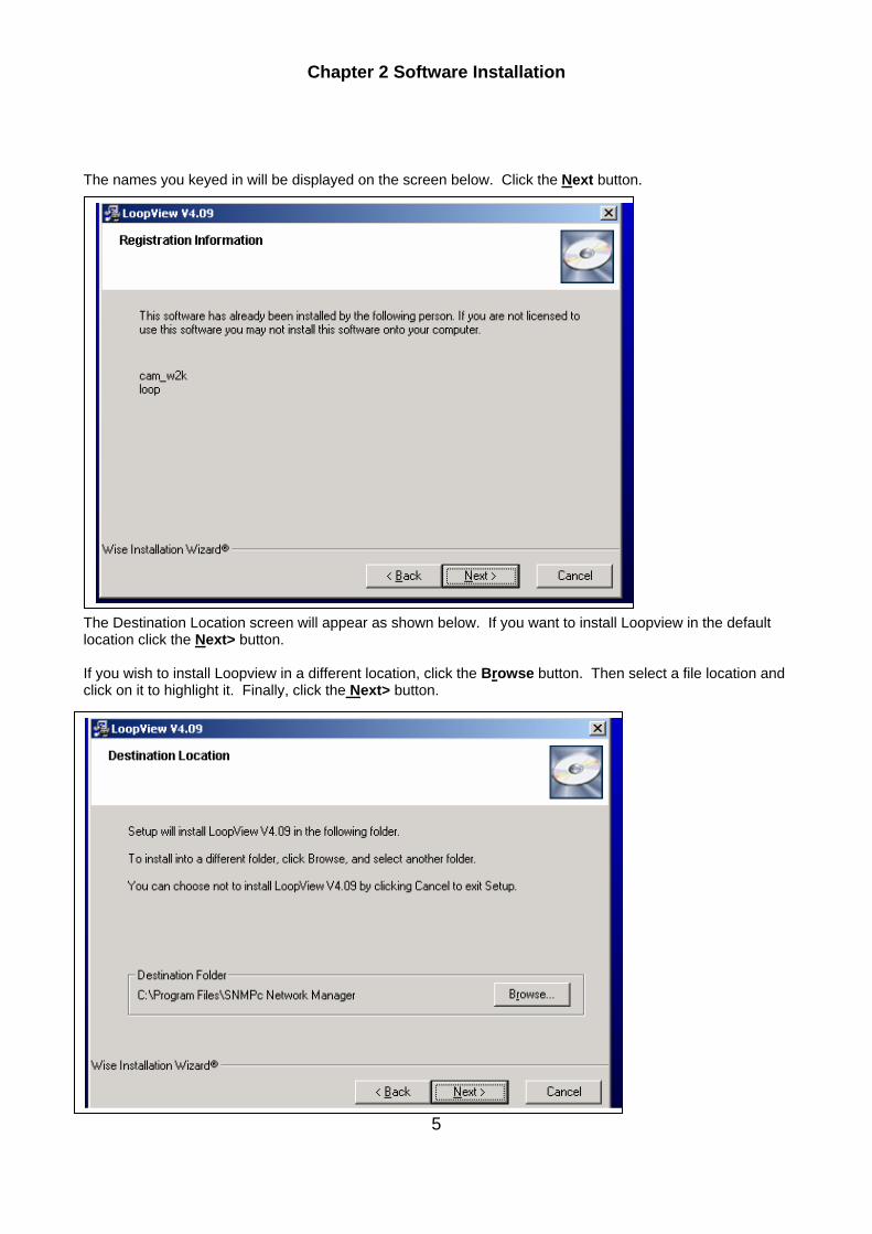
The names you keyed in will be displayed on the screen below. Click the Next button. The Destination Location screen will appear as shown below. If you want to install Loopview in the default location click the Next> button. If you wish to install Loopview in a different location, click the Browse button. Then select a file location and click on it to highlight it. Finally, click the Next> button.

Chapter 2 Software Installation
6
The Backup Replaced Files screen will appear. If you wish to make copies of all files replaced during the Loopview installation process click the Yes button. Then click the Browse button. Then select a file location and click on it to highlight it. Finally, click the Next> button.
If you do not wish to make backup copies click the No button. Then click the Next> button. Note: If you ever remove the Loopview software and wish to restore your system to its previous state, you must make backup copies now.
The Start Installation screen will appear. Click the Next> button.
Chapter 2 Software Installation
7
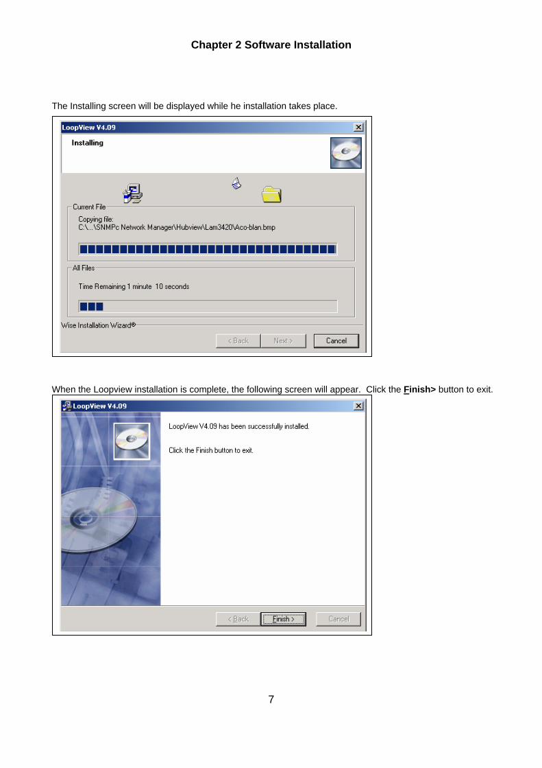
The Installing screen will be displayed while he installation takes place. When the Loopview installation is complete, the following screen will appear. Click the Finish> button to exit.

Chapter 2 Software Installation
8
2.2.1.2 Uninstalling Loopview V4.09 Software Use the following procedure if you wish to uninstall Loopview V4.09 software. Click on the Start button. A pop-up menu will appear. Move your mouse cursor to the Settings heading. An expanded menu will appear. Click on the Control Panel heading. The Control Panel screen will appear. Double-Click on the Add/Remove Programs icon.
Chapter 2 Software Installation
9
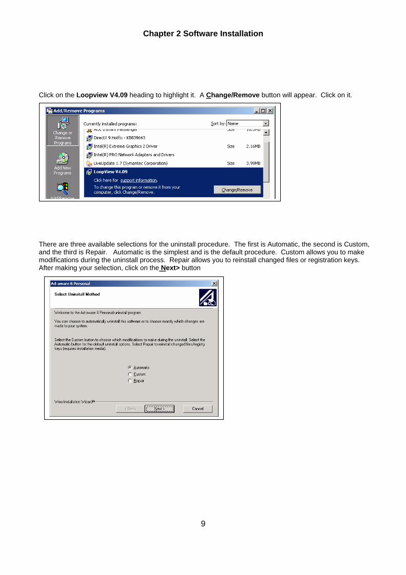
Click on the Loopview V4.09 heading to highlight it. A Change/Remove button will appear. Click on it. There are three available selections for the uninstall procedure. The first is Automatic, the second is Custom, and the third is Repair. Automatic is the simplest and is the default procedure. Custom allows you to make modifications during the uninstall process. Repair allows you to reinstall changed files or registration keys. After making your selection, click on the Next> button
Chapter 2 Software Installation
10
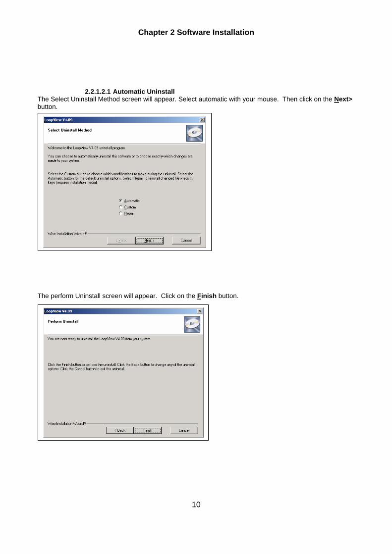
2.2.1.2.1 Automatic Uninstall The Select Uninstall Method screen will appear. Select automatic with your mouse. Then click on the Next> button. The perform Uninstall screen will appear. Click on the Finish button.
Chapter 2 Software Installation
11
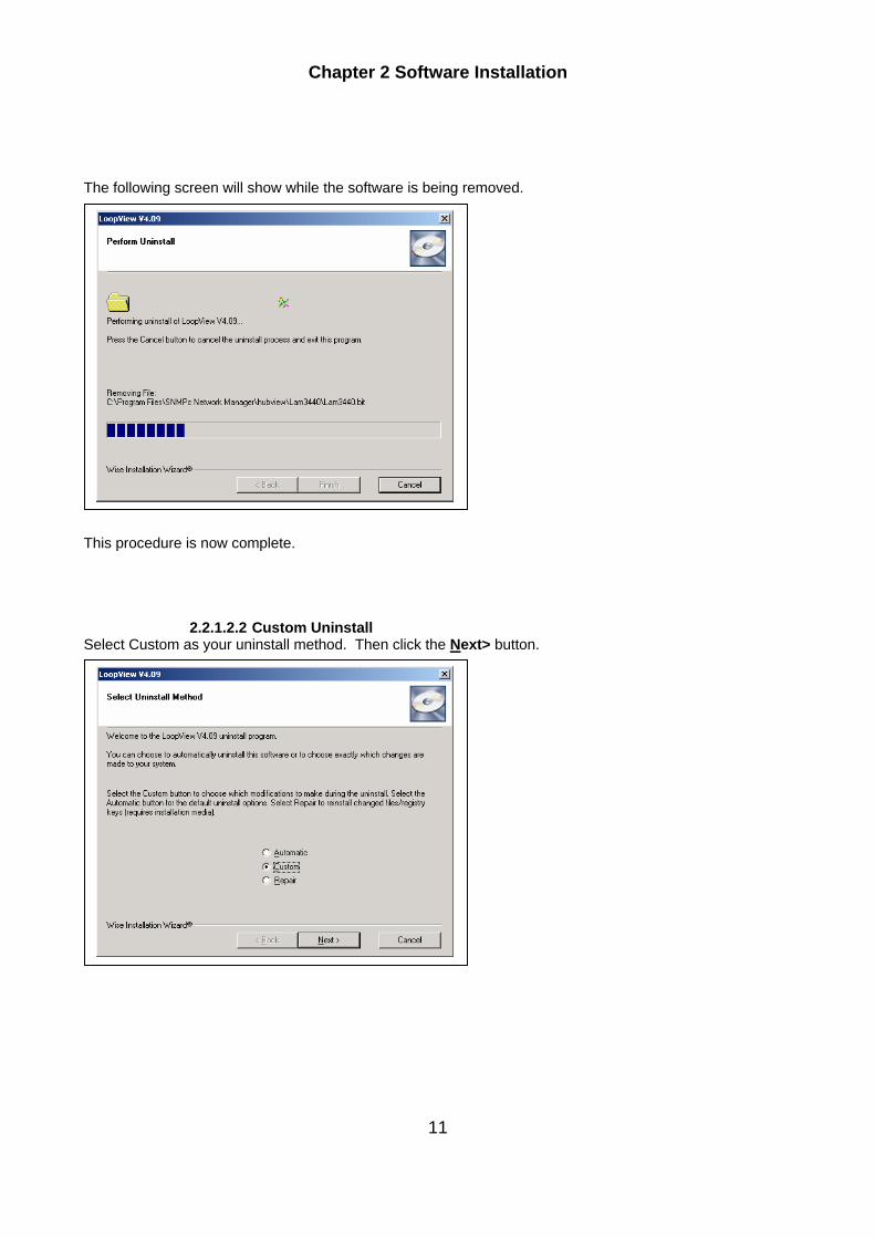
The following screen will show while the software is being removed. This procedure is now complete.
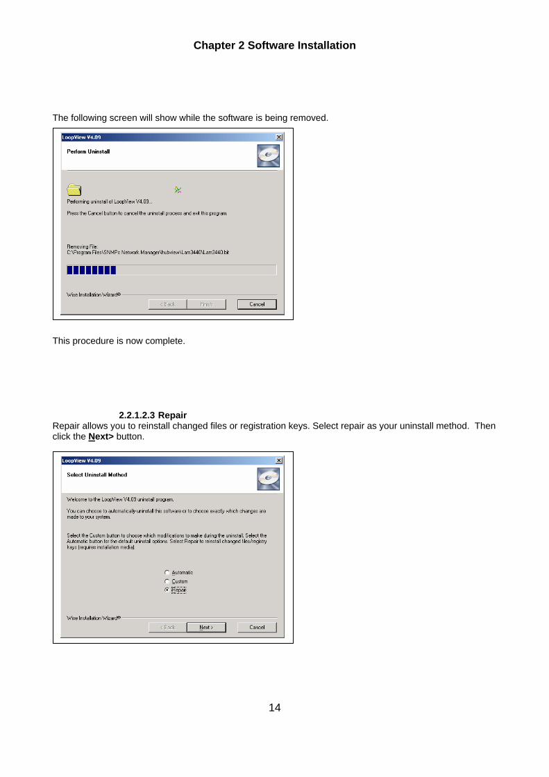
2.2.1.2.2 Custom Uninstall Select Custom as your uninstall method. Then click the Next> button.

Chapter 2 Software Installation
12
The Select Private Files to Remove screen will appear. Click the Select All button. Then click the Next> button.
The Select Directories to Remove screen will appear. Click the Select All button. Then click the Next> button.

Chapter 2 Software Installation
13
The Select Registry Keys to Remove screen will appear. Click the Select All button. Then click the Next> button.
The Perform Uninstall screen will appear. Click the Finish button.
Chapter 2 Software Installation
14
The following screen will show while the software is being removed. This procedure is now complete.
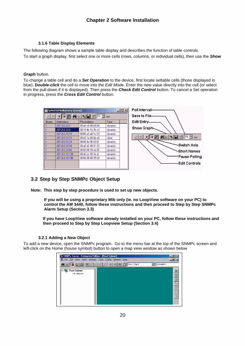
2.2.1.2.3 Repair Repair allows you to reinstall changed files or registration keys. Select repair as your uninstall method. Then click the Next> button.

Chapter 2 Software Installation
15
The Perform Repair screen will appear. Click the Finish button.
The following screen will show while the repair process takes place.
This procedure is now complete.

Chapter 2 Software Installation
16

Chapter 2 Software Installation
17
3 SNMPc and LoopView Setup
3.1 Starting the Server and Getting Logged On To SNMPc. After you reboot the system and logon to Windows, SNMPc will be started automatically. Move your mouse to the bottom of the screen and locate the SNMPc Server icon. It may take a moment after logging on to Windows before the icon is displayed. Press the SNMPc Server icon. The SNMPc Frame Window and logon prompt will be displayed. After first installing SNMPc there is one user named Administrator with no password. So you only need to press the OK button to logon.
3.1.1 Using SNMPc Console Elements The following diagram and the table that follows it show the main elements of the SNMPc console.

Chapter 2 Software Installation
18
Table 3- 1 Console Functions Table
3.1.2 SNMPc Console Button Commands
The following diagram shows the function of each button in the Main Button Bar and Edit Button Bar. Each of these buttons has a corresponding main menu item.
3.1.3 SNMPc Selection Tool
If you can’t see the selection tool, use the View/Selection Tool menu to show it. Use the Selection Tool to manipulate objects from one of several databases. Use the drag control at the right of the Selection Tool to change its size. Select one of the Selection Tool tabs to display a tree control for the database. Use the right-click menu inside a selection tree for database-specific commands.
Table 3- 2 Selection Tool Description Table

Chapter 2 Software Installation
19
3.1.4 SNMPc Event Log Tool
The Event Log Tool displays different filtered views of the SNMPc event log. If you can’t see the Event Log Tool, use the View/Event Log Tool menu to show it. Select the Current tab to show unacknowledged (current) events. These events have a colored box at the left side of the log entry. The color of map objects is determined by the highest priority unacknowledged event for that object. Select the History tab to show all events, including acknowledged and unacknowledged events. Select one of the Custom tabs and use the right-click Filter View menu to specify what events should be displayed for that tab. Double-click an event entry to display a Map View window with the corresponding device icon visible. To quickly view events for a particular device, first select the device and then use one of the View Events buttons (or the View/Active Events and View/History Events menus). This will show the device events in a separate window in the View Windows area. To remove one or more events, select the events and press the Delete key. To acknowledge (remove current status of) an event, select the event and use the right-click Acknowledge menu. To completely clear the event log, use the File/Clear Events menu.
3.1.5 Working with the SNMPc Map Database
3.1.5.1 Using the SNMPc Map Selection Tree
Locate the Selection Tool on the right side of the console. If you can’t see the Selection Tool, use the View/Selection Tool menu to show it. Select the first tab marked Map. The displayed Map Selection tree shows all icon objects in the map. This includes subnets (which contain lower map levels), devices, and goto icons. Networks and links are not shown in the map selection tree. Each icon in the Map Selection Tree is colored according to the status of the represented object. Subnet icons (and the top level Root Subnet icon) show the highest priority color of all underlying objects. Single-click on the small box to the left of a subnet icon (folder icon) to open or close that sublevel in the selection tree. Double-click on a subnet name (right of folder icon) to open that subnet level as a Map View window (see below). Left-click on any object name to select that object. Use the shift and ctrl keys to select multiple objects. Use the Delete key to remove selected objects. After opening two subnet levels, select multiple device names and drag the mouse to move them from one subnet to another. Note that any attached links and networks are not moved, and links will be deleted during the move (you can re-add them manually later). Right-click on a device icon (colored rectangle) or name to see the available Right-Click Menus. Use these menus to edit the selected object properties, display tables, and run other custom menus. Open a subnet tree and use the Insert/Map Object menus or Edit Button Bar buttons to add icon objects to the subnet tree.
Chapter 2 Software Installation
20
3.1.6 Table Display Elements
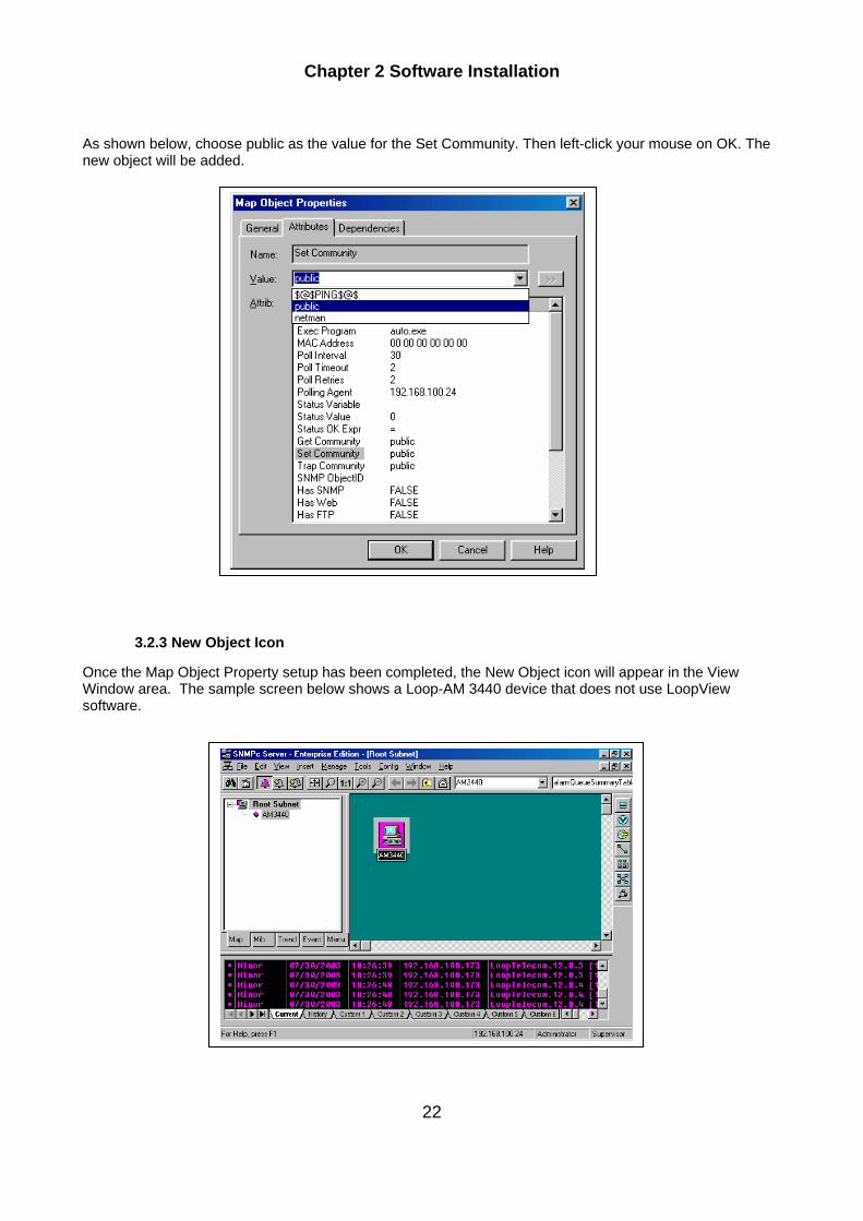
The following diagram shows a sample table display and describes the function of table controls. To start a graph display, first select one or more cells (rows, columns, or individual cells), then use the Show Graph button. To change a table cell and do a Set Operation to the device, first locate settable cells (those displayed in blue). Double-click the cell to move into the Edit Mode. Enter the new value directly into the cell (or select from the pull-down if it is displayed). Then press the Check Edit Control button. To cancel a Set operation in progress, press the Cross Edit Control button.
3.2 Step by Step SNMPc Object Setup
Note: This step by step procedure is used to set up new objects. If you will be using a proprietary Mib only (ie. no LoopView software on your PC) to control the AM 3440, follow these instructions and then proceed to Step by Step SNMPc Alarm Setup (Section 3.3)
If you have LoopView software already installed on your PC, follow these instructions and then proceed to Step by Step Loopview Setup (Section 3.4)
3.2.1 Adding a New Object To add a new device, open the SNMPc program. Go to the menu bar at the top of the SNMPc screen and left-click on the Home (house symbol) button to open a map view window as shown below

Chapter 2 Software Installation
21
Left-click your mouse on the Insert button in the menu at the top of the window. A drop down menu will will appear.. Move your mouse cursor to Map Object, and then over to Device. Left click your mouse on the word Device.
.
3.2.2 Setting Up the Map Object Properties The Map Object Properties screen will appear as shown below. Move your cursor to the Label fieldand key in a label name for the device. Then go down one row to the Address field and key in the IP address of the device you are adding
Left-click the Attributes button with your mouse.
Chapter 2 Software Installation
22
As shown below, choose public as the value for the Set Community. Then left-click your mouse on OK. The new object will be added.
3.2.3 New Object Icon
Once the Map Object Property setup has been completed, the New Object icon will appear in the View Window area. The sample screen below shows a Loop-AM 3440 device that does not use LoopView software.
Chapter 2 Software Installation
23
Note: The bell shaped icon at the top of the screen (beneath the Edit command) is green on the above screen. When the icon appears in pink it indicates that an alarm condition has occurred somewhere on the network you are attached to. If an actual alarm situation occurs on the C5500, the AM 3440 icon will turn pink as well.
The purpose of this explanation is to make you aware that for setup purposes it does not matter if the icons on your screen are pink or green.
To restore any icons to a green color you must clear the event logs. Left-click your mouse on File. A drop-down menu box will appear. Left-click your mouse on Clear Events. A dialogue box will ask “Clear event logs?” Click Yes. Once cleared, pink icons will be restored to a green color..
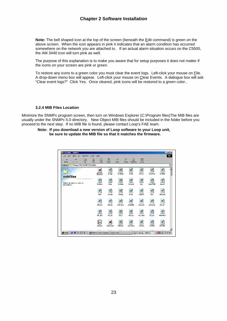
3.2.4 MIB Files Location
Minimize the SNMPc program screen, then turn on Windows Explorer (C:\Program files)The MIB files are usually under the SNMPc 5.0 directory. New Object MIB files should be included in the folder before you proceed to the next step. If no MIB file is found, please contact Loop’s FAE team. Note: If you download a new version of Loop software to your Loop unit, be sure to update the MIB file so that it matches the firmware.
Chapter 2 Software Installation
24
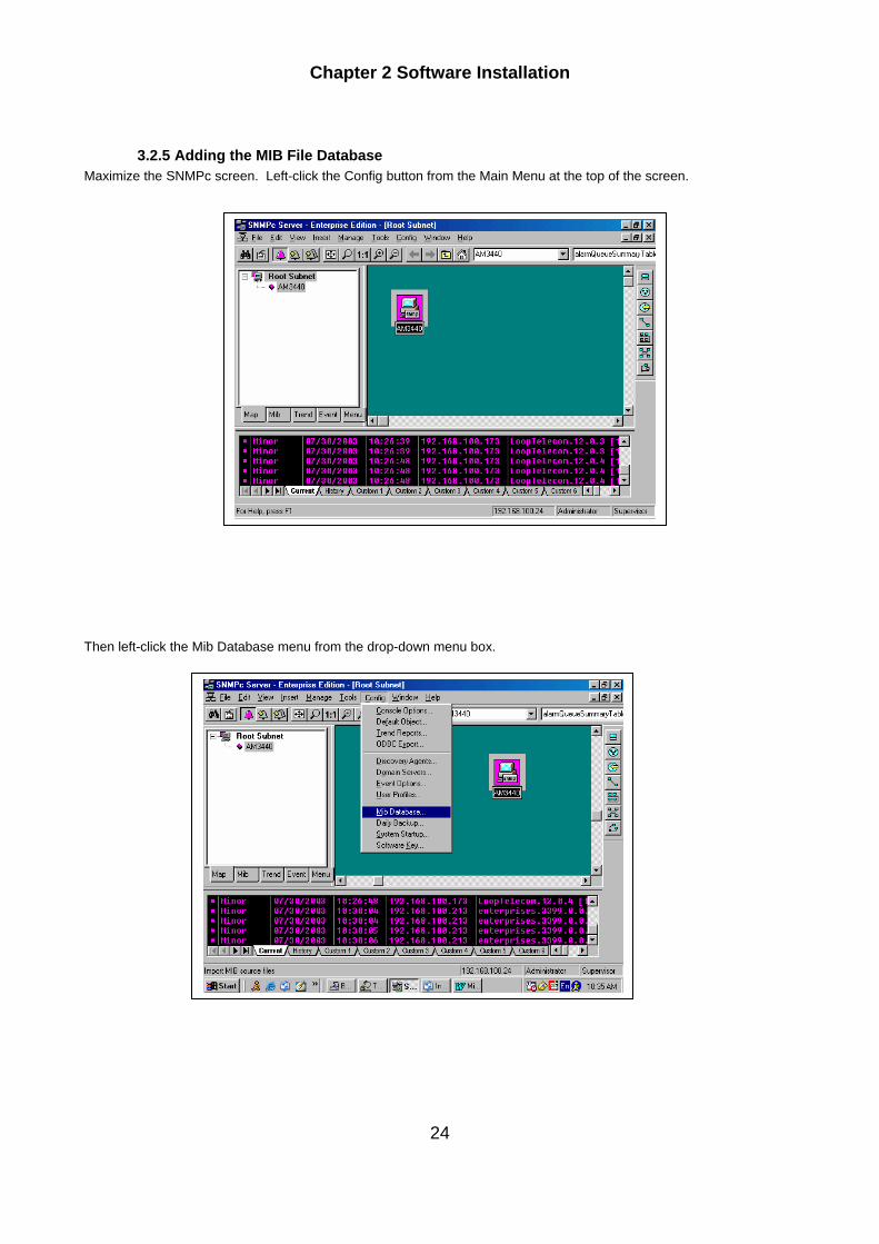
3.2.5 Adding the MIB File Database Maximize the SNMPc screen. Left-click the Config button from the Main Menu at the top of the screen.
Then left-click the Mib Database menu from the drop-down menu box.
Chapter 2 Software Installation
25
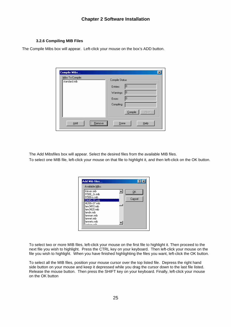
3.2.6 Compiling MIB Files
The Compile Mibs box will appear. Left-click your mouse on the box’s ADD button.
The Add Mibsfiles box will appear. Select the desired files from the available MIB files. To select one MIB file, left-click your mouse on that file to highlight it, and then left-click on the OK button. To select two or more MIB files, left-click your mouse on the first file to highlight it. Then proceed to the next file you wish to highlight. Press the CTRL key on your keyboard. Then left-click your mouse on the file you wish to highlight. When you have finished highlighting the files you want, left-click the OK button. To select all the MIB files, position your mouse cursor over the top listed file. Depress the right hand side button on your mouse and keep it depressed while you drag the cursor down to the last file listed. Release the mouse button. Then press the SHIFT key on your keyboard. Finally, left-click your mouse on the OK button

Chapter 2 Software Installation
26
The Compile Mibs box will appear as below showing the MIB database. Left-click your mouse on the Compile button (under the Compile Status heading ). This will compile all Mib files in the Mibs to Compile box. A confirmation request box will appear as shown below. Left-click your mouse on Yes to compile the MIB files. A prompt will advise you when the compilation process is complete. Left-click the OK button with your mouse.
Then left-click the Done button with your mouse.

Chapter 2 Software Installation
27
3.3 Step by Step AM 3440 Alarm Setup Using Prlvate Mib Note: If you already have LoopView software installed on your PC, you can skip this section and proceed directly to Step by Step LoopView Setup (Section 3.4).
3.3.1 Mib Selection Tree
Left-click your mouse on the Mib button at the bottom of the left-hand side window. The Mib Selection Tree will appear. It shows all compiled, standard, and private mibs. Individual devices can be monitored and managed through the Mib selection Tree.
3.3.2 Using Private Menus
Open the Private subtree to show the Castle Rock and Loop Telecom icons. Open the Loop Telecom files to show the desired Mib elements.

Chapter 2 Software Installation
28
3.3.3 Opening the Loop Telecom Subtree
The Loop Telecom Subtree shows all the controller fields.. In order to activate the Alarms, you will have to set them to ENABLE. The first step is to left-click the Alarm Control Table file listing to highlight it
Then left-click the View button on the top menu bar. . A drop-down menu box will appear as shown below. below. Left-click your mouse on the MIB Table heading.
The following screen will appear. If the alarms are all enabled (as in the sample screen below), the alarm setup process is now complete. If any of the alarms are disabled, click the Edit button on the menu bar at the top of the Control Tables screen.

Chapter 2 Software Installation
29
An Editing Table Entries box will appear as shown below. The Edit Table Entry box shows the name of the Device, the name of the Table and the details of the Table Elements. All Alarms should be set to ENABLE. A drop down box will appear allowing you to select ENABLE by highlighting it with your mouse cursor. After all alarm entries are set at ENABLE left click your mouse on the Done button.
The following screen will show.

Chapter 2 Software Installation
30
3.4 Step by Step LoopView Setup
3.4.1 LoopView Icon
Once you have installed the LoopView software, the new Object Device Icon will appear on the screen as shown below.
After you double click the new Object Device icon with your left mouse button, a graphic representation of the Loop device will appear on the screen. The screen is a GUI environment that allows easy monitoring and management of Loop units. The example below shows a Loop-AM 3440 unit.
Note: The chart appearing in the lower left-hand corner of the above screen automatically displays the protection status if the protection function has been set up. The protection status chart is explained further in the text and illustrations below.

Chapter 2 Software Installation
31
The protection status chart has four fields: Init, Backup Link, Backup Function and Backup Status.
Init. – If an icon appears in one of the Init. Boxes, it means that a card type mismatch has occurred. Double-click on the icon to initialize the card. This will correct the mis-match problem.
Backup Link - If an icon appears it lets you know which card is protecting which card. For example, in the chart below, the card in Slot A is protected by the card in Slot B.
Backup Function - When the light is on, the backup function is on. When the light is off, the backup function is off.
Backup Status - The arrow icons here indicate which card is the working card. ln the screen below, the Slot A card is protected by the Slot B card (Backup Link), the Backup Function is on, and the working card is in Slot A (Backup Status)
Note: If a problem occurs and the protection function switches the communication path from one slot to another, the Backup Status display will show this. In the screen below, the working card is now the card in Slot B.

Chapter 2 Software Installation
32
3.4.2 Setting Up AM 3440 Alarms in Loopview
3.4.2.1 Opening LoopView Double click the AM 3440 icon. The LoopView Main Menu will appear. Click on Alarm (A). A drop down menu will appear. Click on Alarm Control Setup(S)
The Edit Table Entry box will appear on your screen. If all alarms are enabled the process is complete. If any alarms are disabled you must enable them.
3.4.2.2 Opening the Private Subtree
Chapter 2 Software Installation
33
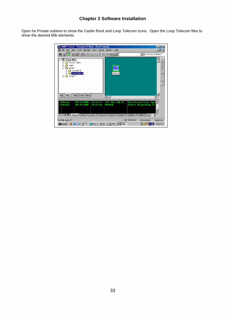
Open he Private subtree to show the Castle Rock and Loop Telecom icons. Open the Loop Telecom files to show the desired Mib elements.

Chapter 3 SNMPc and LoopView Setup
35
3.5 Redundancy function Setup The Redundancy function is a new backup function. By using two servers with one designated as a master and the other as a slave, you can continue monitoring your network if the master system is disabled for any reason.
3.5.1 SNMP Setup SNMP Management Console screen→Config→Backup/Restore
Function Description Note Enable Scheduled Backups Start SNMPc map backup Enable backup Service Start redundancy function This system is currently polling map objects
For Master unit, user needs to click 2 functions.
For Slave unit, user only needs to click one function.
Primary Server Address Master IP Backup Server Address Slave IP

Chapter 3 SNMPc and LoopView Setup
36
Right-click on the Help icon at the bottom right-hand side of Backup/Restore screen.

Chapter 3 SNMPc and LoopView Setup
37
The SNMPc 7.0 Help menu shown below will appear. Inside the managing files, the user can right-click on each topic to get a clear explanation on how to perform the Backup/Restore Database Backup Functions. Managing file: 1. Creating a Database Backup 2. Scheduling Automatic Backups 3. Configuring a Redandant Backup Server 4. Deleting all Database Files 5. Restoring a Database Backup 6. Printing SNMPc Windows 7. Importing SNMPc 4.0 Maps
Chapter 4 Operation
38
4 OPERATION To start LoopView, double click on the LoopView icon.
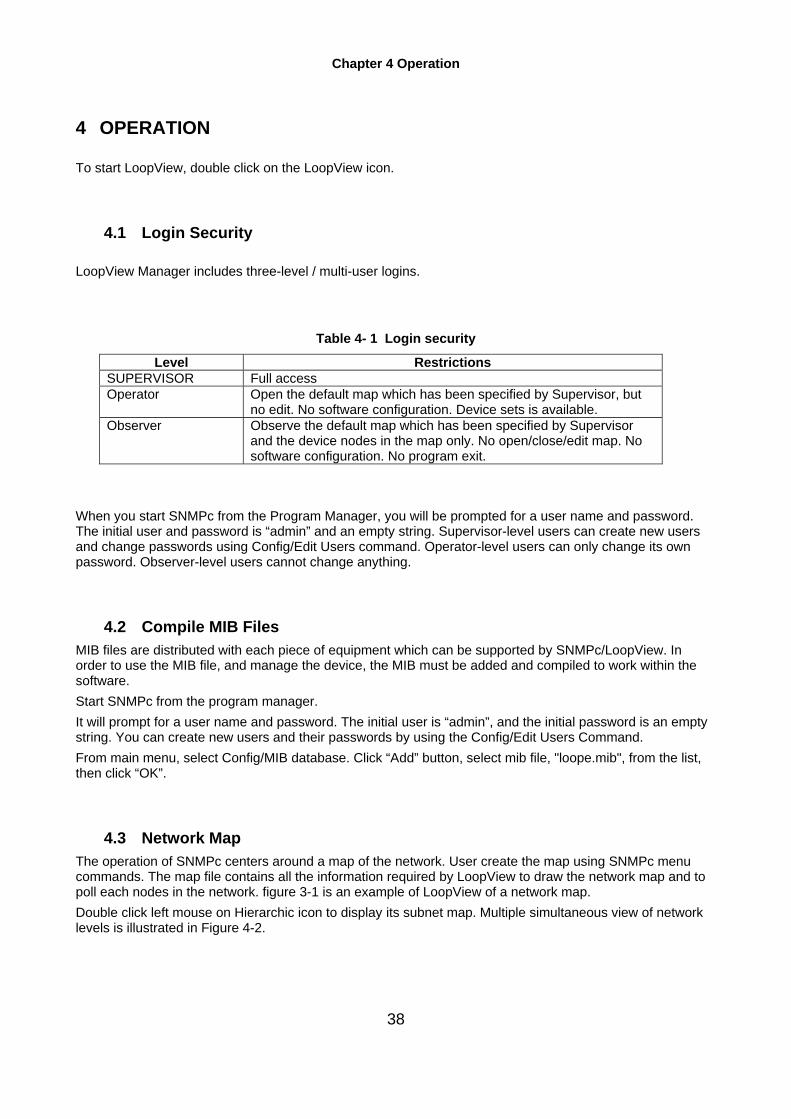
4.1 Login Security LoopView Manager includes three-level / multi-user logins.
Table 4- 1 Login security
Level Restrictions SUPERVISOR Full access Operator Open the default map which has been specified by Supervisor, but
no edit. No software configuration. Device sets is available. Observer Observe the default map which has been specified by Supervisor
and the device nodes in the map only. No open/close/edit map. No software configuration. No program exit.
When you start SNMPc from the Program Manager, you will be prompted for a user name and password. The initial user and password is “admin” and an empty string. Supervisor-level users can create new users and change passwords using Config/Edit Users command. Operator-level users can only change its own password. Observer-level users cannot change anything.
4.2 Compile MIB Files MIB files are distributed with each piece of equipment which can be supported by SNMPc/LoopView. In order to use the MIB file, and manage the device, the MIB must be added and compiled to work within the software. Start SNMPc from the program manager. It will prompt for a user name and password. The initial user is “admin”, and the initial password is an empty string. You can create new users and their passwords by using the Config/Edit Users Command. From main menu, select Config/MIB database. Click “Add” button, select mib file, "loope.mib", from the list, then click “OK”.
4.3 Network Map The operation of SNMPc centers around a map of the network. User create the map using SNMPc menu commands. The map file contains all the information required by LoopView to draw the network map and to poll each nodes in the network. figure 3-1 is an example of LoopView of a network map. Double click left mouse on Hierarchic icon to display its subnet map. Multiple simultaneous view of network levels is illustrated in Figure 4-2.

Chapter 4 Operation
39
Figure 4- 1 Navigation Tree
Figure 4- 2 Multiple network map views
Chapter 4 Operation
40
4.4 Object Layout Network elements are termed “nodes” and are represented on the screen by an icon. There are four types of nodes:Hierarchy Node 1. Goto Node 2. Agent Node 3. Ping Node Hierarchy nodes represent an underlying structure of networks such as a city and a building. Hierarchy nodes can be entered to reveal additional map segments. Goto nodes are indirect links to Hierarchy nodes. It can be used as shortcuts around the map. Agent nodes represent manageable network devices that have SNMP agents in them. Each agent has a unique Node Name, which is displayed on the map, and a Network Address which must be a valid IP address. Ping nodes represent network devices that support IP but do not have an SNMP agent. Networks can be created automatically. Each node is connected to one or more networks. The selected node is the target node for the commands. MIB variables can be inspected by first select the node and use the Edit MIB Variables menu option. To create a network automatically, use the pull-down menu "Discover Nodes" under "Edit". It may take some time for LoopView to poll all available Loop devices attached to the network. This command can be repeated in case some nodes may be missing due to missed polls.
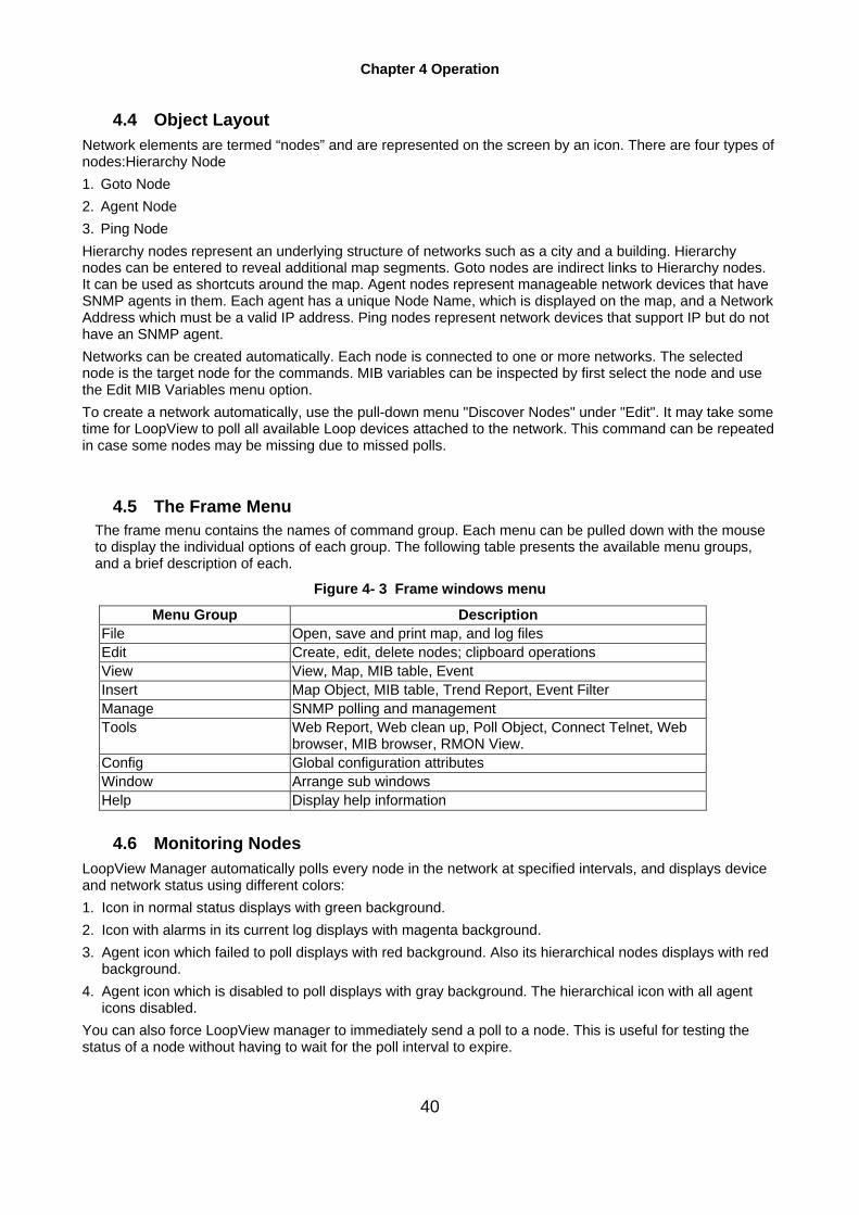
4.5 The Frame Menu The frame menu contains the names of command group. Each menu can be pulled down with the mouse
to display the individual options of each group. The following table presents the available menu groups, and a brief description of each.
Figure 4- 3 Frame windows menu
Menu Group Description File Open, save and print map, and log files Edit Create, edit, delete nodes; clipboard operations View View, Map, MIB table, Event Insert Map Object, MIB table, Trend Report, Event Filter Manage SNMP polling and management Tools Web Report, Web clean up, Poll Object, Connect Telnet, Web
browser, MIB browser, RMON View. Config Global configuration attributes Window Arrange sub windows Help Display help information
4.6 Monitoring Nodes LoopView Manager automatically polls every node in the network at specified intervals, and displays device and network status using different colors: 1. Icon in normal status displays with green background. 2. Icon with alarms in its current log displays with magenta background. 3. Agent icon which failed to poll displays with red background. Also its hierarchical nodes displays with red
background. 4. Agent icon which is disabled to poll displays with gray background. The hierarchical icon with all agent
icons disabled. You can also force LoopView manager to immediately send a poll to a node. This is useful for testing the status of a node without having to wait for the poll interval to expire.
Chapter 4 Operation
41
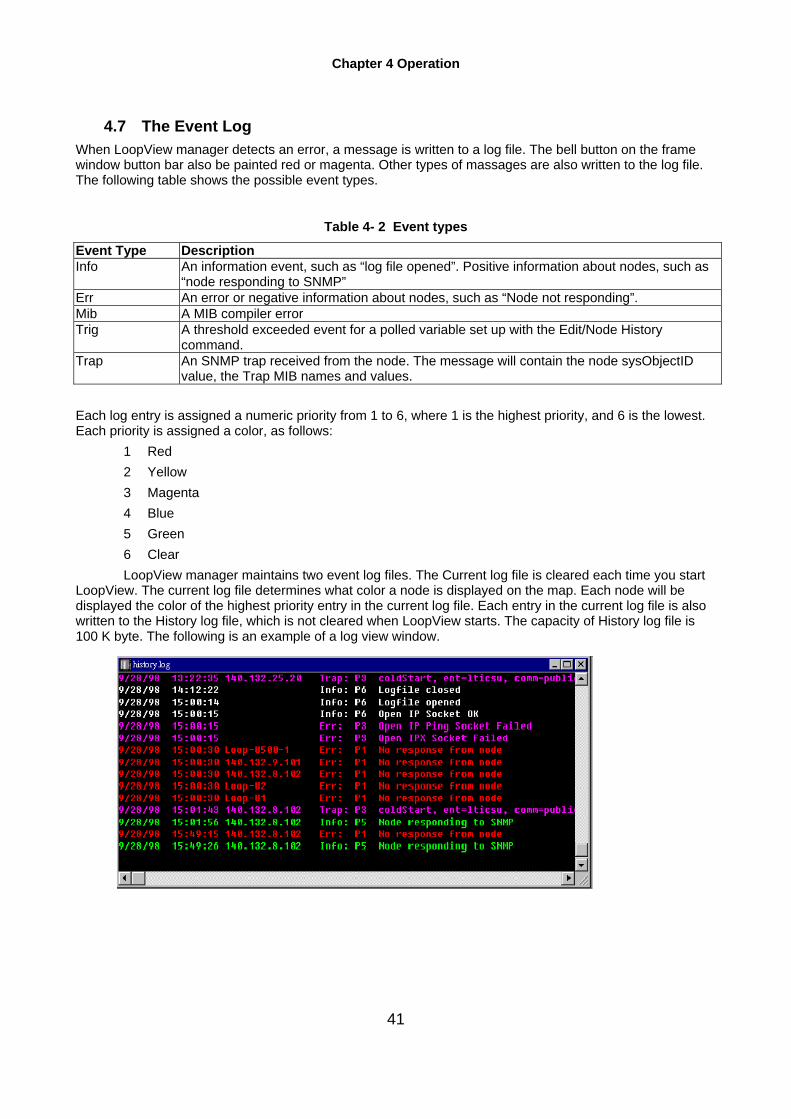
4.7 The Event Log When LoopView manager detects an error, a message is written to a log file. The bell button on the frame window button bar also be painted red or magenta. Other types of massages are also written to the log file. The following table shows the possible event types.
Table 4- 2 Event types
Event Type Description Info An information event, such as “log file opened”. Positive information about nodes, such as
“node responding to SNMP” Err An error or negative information about nodes, such as “Node not responding”. Mib A MIB compiler error Trig A threshold exceeded event for a polled variable set up with the Edit/Node History
command. Trap An SNMP trap received from the node. The message will contain the node sysObjectID
value, the Trap MIB names and values. Each log entry is assigned a numeric priority from 1 to 6, where 1 is the highest priority, and 6 is the lowest. Each priority is assigned a color, as follows:
1 Red 2 Yellow 3 Magenta 4 Blue 5 Green 6 Clear
LoopView manager maintains two event log files. The Current log file is cleared each time you start LoopView. The current log file determines what color a node is displayed on the map. Each node will be displayed the color of the highest priority entry in the current log file. Each entry in the current log file is also written to the History log file, which is not cleared when LoopView starts. The capacity of History log file is 100 K byte. The following is an example of a log view window.
Figure 4- 4 Event log

Chapter 5 Graphic Device Windows
42
5 Graphic Device Windows NOTE: To maintain the high performance of SNMP, close inactive windows to leave no more than
three windows open at the same time. When too many windows are open, each window may not receive timely responses from the target node. This may cause LoopView to reach a false "dead node" conclusion.
5.1 Time Out Configuration Move your mouse cursor to the Loop-AM 3440 icon and right-click your mouse on it. A Properties menu will drop down. Left-click your mouse on the Properties heading. The Map Object Properties box will appear as shown below. Left-click your mouse on the Attributes

Chapter 5 Graphic Device Windows
43
heading at the top of the box. A listing of properties will appear. Left-click your mouse on the Poll Timeout listing, then go to the Value fie d at the top of the box and set it at 40 or more. Then left-click your mouse on the OK button at the bottom of the box.
Chapter 6Loop-AM 3440
44
6 Loop-AM 3440 This section will show the various menus available on the AM 3440. For the specific settings and options available for each menu item, consult the User’s Manual. Note: Note the user manual screens displalyed were reproduced using Loop V3.08 software.
The information displayed on the screen is the same as that displayed by Loop V4.09 software.
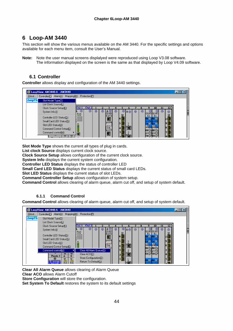
6.1 Controller Controller allows display and configuration of the AM 3440 settings. Slot Mode Type shows the current all types of plug in cards. List clock Source displays current clock source. Clock Source Setup allows configuration of the current clock source. System Info displays the current system configuration. Controller LED Status displays the status of controller LED Small Card LED Status displays the current status of small card LEDs. Slot LED Status displays the current status of slot LEDs. Command Controller Setup allows configuration of system setup. Command Control allows clearing of alarm queue, alarm cut off, and setup of system default.
6.1.1 Command Control Command Control allows clearing of alarm queue, alarm cut off, and setup of system default. Clear All Alarm Queue allows clearing of Alarm Queue Clear ACO allows Alarm Cutoff Store Configuration will store the configuration. Set System To Default restores the system to its default settings

Chapter 6 Loop-AM 3440
45
6.2 Alarm Alarm allows setup and review of the various alarm functions for the AM3440 main unit. List Alarm Control displays various alarm settings. Alarm Control Setup allows setup alarm. Alarm Queue Summary displays a list of the current alarm conditions.
6.3 Mapping Mapping provides a menu to view and setup the TSI map. List Current TSI Map displays the current TSI Map. List All TSI Map displays all TSI Maps. List TSI Map-1 displays the TSI Map-1. List TSI Map-2 displays the TSI Map-2. List TSI Map-3 displays the TSI Map-3. TSI Map Setup allows the configuration of TSI map. Select a New TSI Map allows to select a new TSI map. Clear Map Setup allows you to clear a TSI Map. Copy Map Setup allows you to copy a TSI Map. Switch Map Setup allows you to switch a TSI Maps. View Map by Slot displays the TSI maps by slot.

Chapter 6 Loop-AM 3440
46
6.4 Protection Protection provides a menu to view and setup protection. Dual Power displays the protection status for power supply. Dual Controller displays the protection status for CPU. Link Backup Table displays the table of link backup. Link Backup Status displays the status of link backup.
Chapter 7 Plug-in Cards
47
7 PLUG-IN CARDS This section will show the various menus available on plug-in cards for the AM 3440. For the specific settings and options available for each menu item, consult the User’s Manual.
7.1 ATM/FR Card Note: Note the user manual screens for this card were reproduced using Loop V3.08 software.
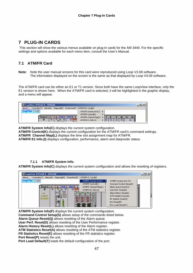
The information displayed on the screen is the same as that displayed by Loop V4.09 software. The ATM/FR card can be either an E1 or T1 version. Since both have the same LoopView interface, only the E1 version is shown here. When the ATM/FR card is selected, it will be highlighted in the graphic display, and a menu will appear. ATM/FR System Info(C) displays the current system configuration. ATM/FR Control(K) displays the current configuration for the ATM/FR card’s command settings. ATM/FR Channel Map(L) displays the time slot assignment map for ATM/FR. ATM/FR E1 Info.(I) displays configuration, performance, alarm and diaqnostic status.
7.1.1 ATM/FR System Info. ATM/FR System Info(C) displays the current system configuration and allows the resetting of registers. ATM/FR System Info(F) displays the current system configuration. Command Control Setup(S) allows setup of the commands listed below. Alarm Queue Reset(Q) allows resetting of the Alarm queue. User Perf. Reset(D) allows resetting of the User Performance register. Alarm History Reset(L) allows resetting of the Alarm register. ATM Statistics Reset(A) allows resetting of the ATM statistics register. FR Statistics Reset(E) allows resetting of the FR statistics register. Port Reset(P) resets the unit. Port Load Default(T) loads the default configuration of the port.

Chapter 7 Plug-in Cards
48
7.1.2 ATM/FR Control ATM/FR Control(K) displays the current configuration for the ATM/FR card’s command settings. ATM/FR Mgmt Table(M) displays ATM/FR management information. ATM/FR Mgmt Setup(S) allows setup of ATM/FR management ATM VC Table(A) displays ATM setup virtual connection information. ATM VC Setup(V) allows virtual connection setup of the ATM mode. FR Statistic Table(T) displays FR mode statistics information. ATM Statistic Table(U) displays ATM mode statistics information. FR Status Table(V) displays FR mode status. ATM Statust Table(R) displays ATM mode status. ATM Line Statistic Table(L) displays ATM mode line statistics information.
7.1.3 ATM/FR Channel Map ATM/FR Channel Map(L) displays the time slot assignment map for ATM/FR. ATM/FR Channel Map Table(D) displays the time slot assignment map for ATM/FR. ATM/FR Channel Map Setup(S) allows configuration of the time slot assignment map for ATM/FR. ATM/FR CSU Channel Map Table(T) displays the time slot assignment map for ATM/FR CSU. ATM/FR CSU Channel Map Setup(I) allows configuration of the time slot assignment map for ATM/FR CSU. ATM/FR DLCI Channel Map Table(T) displays the time slot assignment map for ATM/FR DLCI. ATM/FR DLCI Channel Map Setup(I) allows configuration of time slot assignment map for ATM/FR DLCI.

Chapter 7 Plug-in Cards
49
7.1.4 ATM/FR E1 Info.(I) ATM/FR E1 Info.(I) allows configuration and display of the ATM/FR E1 card settings. ATM/FR E1 Line Control Table(L) displays control settings of the ATM/FR E1 card. ATM/FR E1 Line Control Setup(C) allows configuration of the ATM/FR E1 card control settings. ATM/FR E1 User Perf.(U) lists performance characteristics of the ATM/FR card. These can be cleared. ATM/FR E1 Line Perf.(P) lists performance characteristics of the ATM/FR card. These cannot be cleared. ATM/FR E1 Alarm(A) allows setup and review of the various alarm functions for the ATM/FR card. ATM/FR E1 Diag.(B) allows setup and review of the diagnostic functions of the ATM/FR card.

Chapter 7 Plug-in Cards
50
7.2 DTE Card Note: Note the user manual screens for this card were reproduced using Loop V3.08 software.
The information displayed on the screen is the same as that displayed by Loop V4.09 software.
7.2.1 Control Control allows configuration of the DTE card. List DTE Config displays configuration of the DTE port. DTE Config Setup allows configuration of the DTE port. List DTE Status displays DTE status. List DTE System Info. displays DTE system information.. DTE Command Control allows configuration of the DTE port.
7.2.2 Alarm Alarm allows setup and review of the various alarm functions for the DTE card. DTE Alarm History displays alarm history. DTE Alarm Queue displays alarm queue. DTE Alarm Control displays the various alarm settings. DTE Alarm Setup allows configuration of the various alarm settings.
7.2.3 Diagnostic Diagnostic allows display and setup of various diagnostic functions. List Line Diag. Control displays line diagnostics control information. Loopback Setting allows configuration of the various loopbacks on the DTE card.

Chapter 7 Plug-in Cards
51
7.3 6-Port DTU Card Note: Note the user manual screens for this card were reproduced using Loop V3.08 software.
The information displayed on the screen is the same as that displayed by Loop V4.09 software.
7.3.1 Control Dtu-6 Control allows configuration of the 6-port DTU card. List Rem-DTE Config displays a list of the control information for the remote DTE port. Rem-DTE Config Setup allows configuration of the remote DTE port. List Rem-LED Status displays status of remote LEDs. List Line Diagnostic displays a list of the diagnostics of the DTU card. Loopback Setting allows configuration of the various loopbacks on the DTU card. List Line Config. displays line configuration. List Config. Setup allows setup of line configuration. List Alarm Control displays the various alarm settings. Alarm Control Setup allows configure the various alarm settings. List Alarm History displays the various alarm history. Command Control Setup allows configuration of the various commands on the DTU card
7.3.2 Mapping Mapping provides a menu to view TSI map. Current Slot TSI Map displays the current TSI map of DTU card. Current Slot TSI Map displays current slot TSI Map
7.3.3 Local Performance Local Performance gives a list of standard performance characteristics for the DTU card. List User Current Perf. displays a list of the current performance for the DTU port. List User Interval Perf. displays a list of the interval performance for the DTU port. List User Total Perf. displays a list of the entire performance characteristics for the DTU port.

Chapter 7 Plug-in Cards
52
7.4 10-Port DTU Card Note: Note the user manual screens for this card were reproduced using Loop V3.08 software.
The information displayed on the screen is the same as that displayed by Loop V4.09 software.
7.4.1 Control Control allows configuration of the 10-port DTU card. List Rem-DTE Config displays a list of the control information for the remote DTE port. Rem-DTE Config Setup allows configuration of the remote DTE port. List Rem-Led Status displays status of remote LEDs. List Line Diagnostic displays a list of the diagnostics of the DTU card. Loopback Setting allows configuration of the various loopbacks on the DTU card. List Line Config. displays line configuration. List Config. Setup allows setup of line configuration. List Alarm Control displays the various alarm settings. Alarm Control Setup allows configure the various alarm settings. List Alarm History displays the various alarm history. Command Control Setup allows configuration of the various commands on the DTU card
7.4.2 Mapping Mapping provides a menu to view the TSI map. Current Slot TSI Map displays the current TSI map of DTU card.
Chapter 7 Plug-in Cards
53
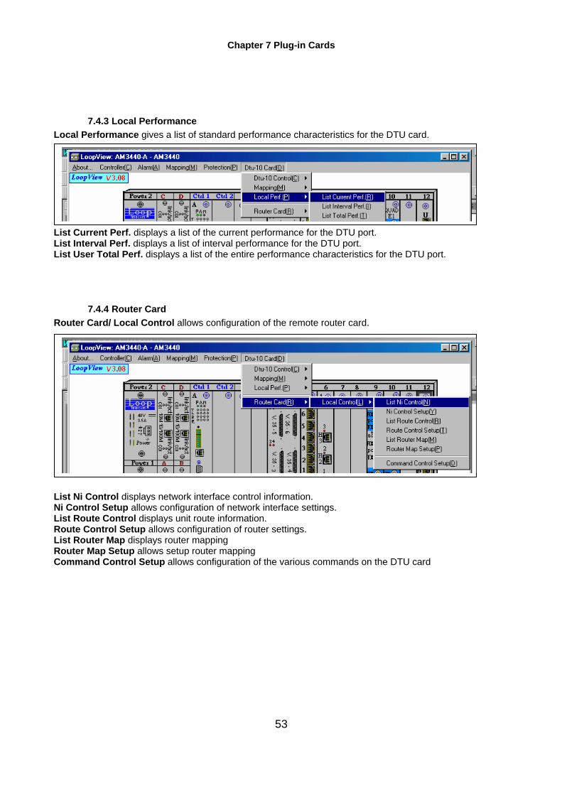
7.4.3 Local Performance Local Performance gives a list of standard performance characteristics for the DTU card. List Current Perf. displays a list of the current performance for the DTU port. List Interval Perf. displays a list of interval performance for the DTU port. List User Total Perf. displays a list of the entire performance characteristics for the DTU port.
7.4.4 Router Card Router Card/ Local Control allows configuration of the remote router card. List Ni Control displays network interface control information. Ni Control Setup allows configuration of network interface settings. List Route Control displays unit route information. Route Control Setup allows configuration of router settings. List Router Map displays router mapping Router Map Setup allows setup router mapping Command Control Setup allows configuration of the various commands on the DTU card
Chapter 7 Plug-in Cards
54
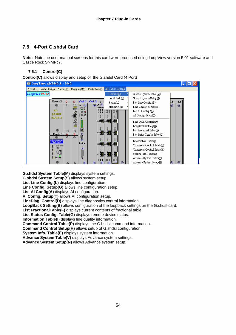
7.5 4-Port G.shdsl Card Note: Note the user manual screens for this card were produced using LoopView version 5.01 software and Castle Rock SNMPc7.
7.5.1 Control(C) Control(C) allows display and setup of the G.shdsl Card (4 Port) G.shdsl System Table(M) displays system settings. G.shdsl System Setup(S) allows system setup. List Line Config.(L) displays line configuration. Line Config. Setup(G) allows line configuration setup. List AI Config(A) displays AI configuration. AI Config. Setup(T) allows AI configuration setup. LineDiag. Control(D) displays line diagnostics control information. LoopBack Setting(B) allows configuration of the loopback settings on the G.shdsl card. List FractionalTable(F) displays current contents of fractional table. List Status Config. Table(G) displays remote device status. Information Table(I) displays line quality information. Command Control Table(P) displays the G.hsdsl command information. Command Control Setup(H) allows setup of G.shdsl configuration. System Info. Table(E) displays system information. Advance System Table(V) displays Advance system settings. Advance System Setup(N) allows Advance system setup.
Monday, March 7, 2005 Waiting for Anna to give new pic to Winston—delete Fractional Table Setup(R)

Chapter 7 Plug-in Cards
55
7.5.1.1 G.shdsl System Table(M) G.shdsl System Table(M) displays system settings.
7.5.1.2 G.shdsl System Setup(S) G.shdsl System Setup(S) allows system setup.
7.5.1.3 List Line Config.(L) List Line Config.(L) displays line configuration.
7.5.1.4 Line Config. Setup(G) Line Config. Setup(G) allows line configuration setup.

Chapter 7 Plug-in Cards
56
7.5.1.5 List AI Config(A) List AI Config(A) displays AI configuration.
7.5.1.6 AI Config. Setup(T) AI Config. Setup(T) allows AI configuration setup.
7.5.1.7 LineDiag. Control(D) LineDiag. Control(D) displays line diagnostics control information.
Chapter 7 Plug-in Cards
57
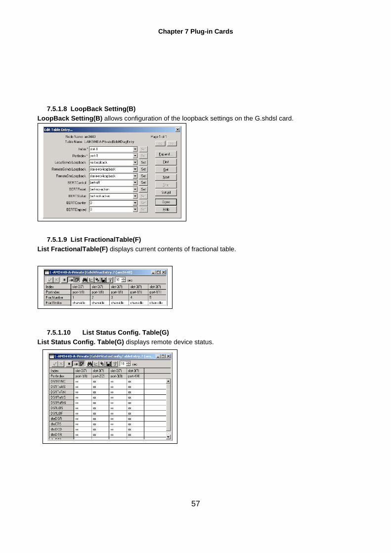
7.5.1.8 LoopBack Setting(B) LoopBack Setting(B) allows configuration of the loopback settings on the G.shdsl card.
7.5.1.9 List FractionalTable(F) List FractionalTable(F) displays current contents of fractional table.
7.5.1.10 List Status Config. Table(G) List Status Config. Table(G) displays remote device status.
Chapter 7 Plug-in Cards
58
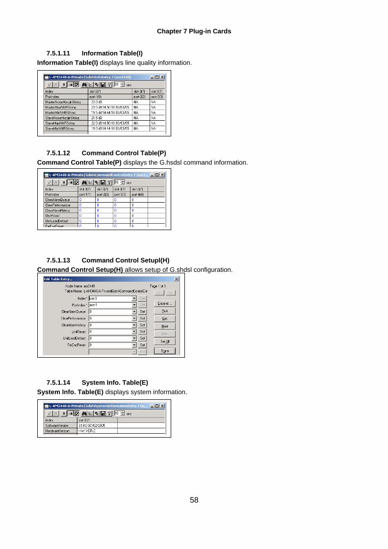
7.5.1.11 Information Table(I) Information Table(I) displays line quality information.
7.5.1.12 Command Control Table(P) Command Control Table(P) displays the G.hsdsl command information.
7.5.1.13 Command Control Setupl(H) Command Control Setup(H) allows setup of G.shdsl configuration.
7.5.1.14 System Info. Table(E) System Info. Table(E) displays system information.

Chapter 7 Plug-in Cards
59
7.5.1.15 Advance System Table(V) Advance System Table(V)
7.5.1.16 Advance System Setup(N) Advance System Setup(N)
7.5.2 LocalPerf(P) LocalPerf(P) displays performance of the G.shdsl card. Current Perf.(R) displays a list of the current performance for the G.shdsl card. Total Perf.(T) displays a list of the entire performance characteristics for the G.shdsl card. Interval Perf.(I) displays a list of the interval performance for the G.shdsl card.

Chapter 7 Plug-in Cards
60
7.5.2.1 Current Perf.(R) Current Perf.(R) displays a list of the current performance for the G.shdsl card.
7.5.2.2 Total Perf.(T) Total Perf.(T) displays a list of the entire performance characteristics for the G.shdsl card.
7.5.2.3 Interval Perf.(I) Interval Perf.(I) displays a list of the interval performance for the G.shdsl card.
Chapter 7 Plug-in Cards
61
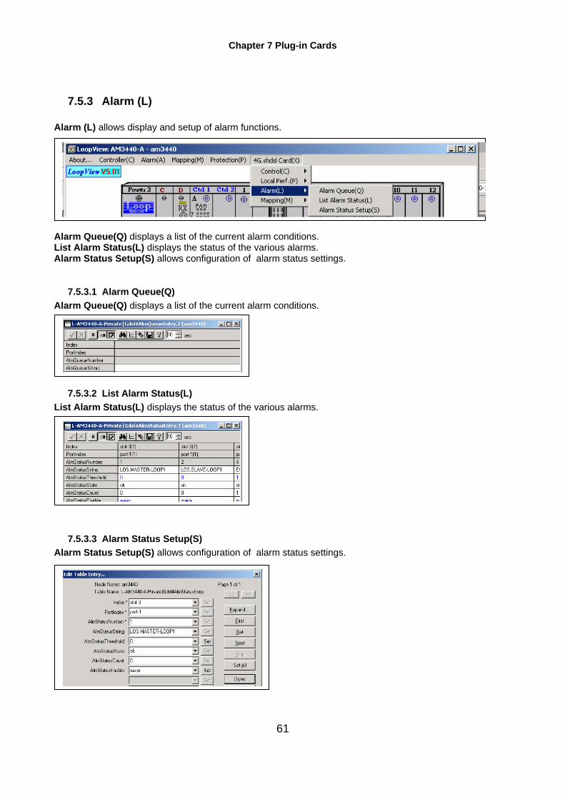
7.5.3 Alarm (L)
Alarm (L) allows display and setup of alarm functions. Alarm Queue(Q) displays a list of the current alarm conditions. List Alarm Status(L) displays the status of the various alarms. Alarm Status Setup(S) allows configuration of alarm status settings.
7.5.3.1 Alarm Queue(Q) Alarm Queue(Q) displays a list of the current alarm conditions.
7.5.3.2 List Alarm Status(L) List Alarm Status(L) displays the status of the various alarms.
7.5.3.3 Alarm Status Setup(S) Alarm Status Setup(S) allows configuration of alarm status settings.

Chapter 7 Plug-in Cards
62
7.5.4 Mapping(M) Mapping(M) provides a menu to view the TSI map. Current Slot TSI Map(R) displays the current slot G.hdsl TSI map.
7.5.4.1 Current Slot TSI Map(R) Current Slot TSI Map(R) displays the current slot G.hdsl TSI map.

Chapter 7 Plug-in Cards
63
7.6 E1 Card Note: Note the user manual screens for this card were reproduced using Loop V3.08 software.
The information displayed on the screen is the same as that displayed by Loop V4.09 software. Each device can be selected for review or modification. When the device is selected, it will be highlighted in the graphic display, and a menu will appear.
7.6.1 Local Control(C) Local Control allows configuration of the rack card. \ List Line Control displays line control information. Line Control Setup allows configuration of the E1 port. List Line Diag. Control displays line diagnostics control information. System Control Setup allows configuration of the system settings. LoopBack Setting allows configuration of the various loopback features. E1 System Info. displays E1 system information. List Command Control displays the E1 command information. Command Control Setup allows configuration of the system E1 setup.
7.6.2 Local Performance E1 Card Local Performance/User Performance gives a list of standard performance characteristics for the E1 card. These characteristics cannot be cleared. User Perf. displays performance of the E1 card. Line Perf. displays performance of the E1 card’s line. Line Availability Perf. displays line availability performance of the E1 card.

Chapter 7 Plug-in Cards
64
7.6.2.1 User Performance User Performance displays performance of the E1 card. User Current Perf. displays a list of the current performance for the E1 card.. User Interval Perf. displays a list of the interval performance for the E1 card. User Total Perf. displays a list of the entire performance characteristics for the E1 card. User Seven Days Perf. displays a list of the past seven days performance.
7.6.2.2 Line Performance Line Performance displays performance of the E1 card’s line. Line Current Perf. displays a list of the performance for the E1 card’s line. Line Interval Perf. displays a list of the performance for the E1 card’s interval. Line Total Perf. displays a list of the entire performance characteristics for the E1 card’s line. Line Seven Days Perf. displays a list of the past seven days’ performance.
7.6.3 Local Alarm Local Alarm allows setup and review of the various alarm functions for the E1 card. List Alarm Control displays the various alarm settings. Alarm Control Setup allows configuration of the various alarm settings. List Threshold displays the alarm thresholds. Threshold Setup allows configuration of the alarm thresholds. List Alarm Queue displays the history of the various alarm queue. List Alarm History displays the history of the various alarms.

Chapter 7 Plug-in Cards
65
7.6.4 Mapping Mapping provides a menu to view the TSI map. Current TSI Map displays the current E1 TSI map.

Chapter 7 Plug-in Cards
66
7.7 Quad E1 Card Note: Note the user manual screens for this card were reproduced using Loop V3.08 software.
The information displayed on the screen is the same as that displayed by Loop V4.09 software. Each device can be selected for review or modification. When the device is selected, it will be highlighted in the graphic display, and a menu will appear.
7.7.1 Local Control Local Control allows configuration of the rack card. List Line Control displays line control information. Line Control Setup allows configuration of the Quad E1 port. List Line Diag. Control displays line diagnostics control information. LoopBack Setting allows configuration of the various loopback features. QE1 System Info. displays Quad E1 system information. List Command Control displays the Quad E1 command information. Command Control Setup allows configuration of the Quad E1 system setup.
7.7.2 Local Performance E1 Card Local Performance/User Performance gives a list of standard performance characteristics for the E1 card. These characteristics cannot be cleared. User Perf. displays performance of the Quad E1 card. Line Perf. displays performance of the Quad E1 card’s line. Line Availability Perf. displays line availability performance of the Quad E1 card.
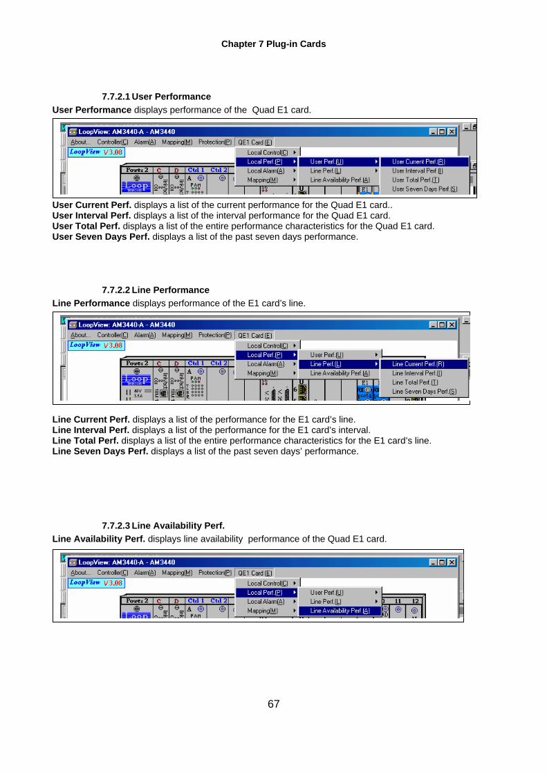
Chapter 7 Plug-in Cards
67
7.7.2.1 User Performance User Performance displays performance of the Quad E1 card. User Current Perf. displays a list of the current performance for the Quad E1 card.. User Interval Perf. displays a list of the interval performance for the Quad E1 card. User Total Perf. displays a list of the entire performance characteristics for the Quad E1 card. User Seven Days Perf. displays a list of the past seven days performance.
7.7.2.2 Line Performance Line Performance displays performance of the E1 card’s line. Line Current Perf. displays a list of the performance for the E1 card’s line. Line Interval Perf. displays a list of the performance for the E1 card’s interval. Line Total Perf. displays a list of the entire performance characteristics for the E1 card’s line. Line Seven Days Perf. displays a list of the past seven days’ performance.
7.7.2.3 Line Availability Perf. Line Availability Perf. displays line availability performance of the Quad E1 card.
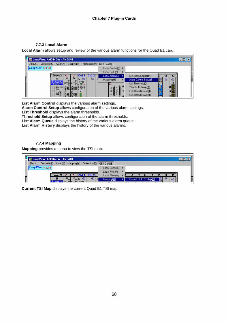
Chapter 7 Plug-in Cards
68
7.7.3 Local Alarm Local Alarm allows setup and review of the various alarm functions for the Quad E1 card. List Alarm Control displays the various alarm settings. Alarm Control Setup allows configuration of the various alarm settings. List Threshold displays the alarm thresholds. Threshold Setup allows configuration of the alarm thresholds. List Alarm Queue displays the history of the various alarm queue. List Alarm History displays the history of the various alarms.
7.7.4 Mapping Mapping provides a menu to view the TSI map. Current TSI Map displays the current Quad E1 TSI map.
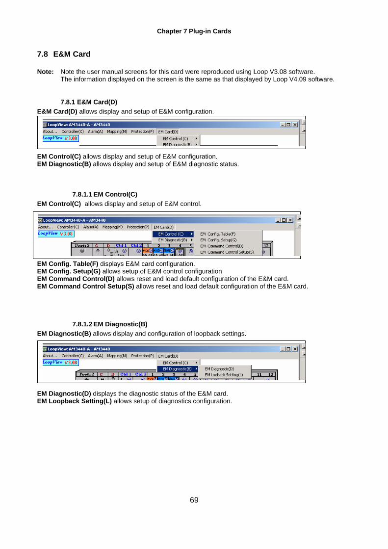
Chapter 7 Plug-in Cards
69
7.8 E&M Card Note: Note the user manual screens for this card were reproduced using Loop V3.08 software.
The information displayed on the screen is the same as that displayed by Loop V4.09 software.
7.8.1 E&M Card(D) E&M Card(D) allows display and setup of E&M configuration. EM Control(C) allows display and setup of E&M configuration. EM Diagnostic(B) allows display and setup of E&M diagnostic status.
7.8.1.1 EM Control(C) EM Control(C) allows display and setup of E&M control. EM Config. Table(F) displays E&M card configuration. EM Config. Setup(G) allows setup of E&M control configuration EM Command Control(D) allows reset and load default configuration of the E&M card. EM Command Control Setup(S) allows reset and load default configuration of the E&M card.
7.8.1.2 EM Diagnostic(B) EM Diagnostic(B) allows display and configuration of loopback settings. EM Diagnostic(D) displays the diagnostic status of the E&M card. EM Loopback Setting(L) allows setup of diagnostics configuration.

Chapter 7 Plug-in Cards
70
7.9 FOM Card Note: The user manual screens for this card were produced using Loop V6.0 software. Click on the Loop-AM 3440-A icon. The AM 3440 - A GUI will appear. Click once on the FOM Card GUI. The FOM Card(F) heading will appear at the top of the screen. Click on it.

Chapter 7 Plug-in Cards
71
A drop-down menu will appear. Control(C) allows setup and display of FOM card. System Control Table(S) displays system information. System Control Setrup(T) allows system setup. FOM Status Table(U) displays FOM status. Diag. Table(G) displays diagnostic items (eg. loopback, BERT test, etc.) Diag. Setup(I) allows setup of diagnostic items. Alarm Status Table(M) displays alarm status. Alarm Status Setup(L) allows alarm setup. Command Control Table(A) displays alarm info. Command Control Setup(N) allows user to clear alarm history, clear optical error, return to default,etc. System Info. Table (F) displays software and hardware version. Optical Type Table(O) displays optical type Apsd Table(P) displays Apsd (autopulse shutdown) status Apsd Setup(D) allows user to enable Apsd, set pulse repeat time, etc.

Chapter 7 Plug-in Cards
72
7.9.1 Remote Loop-0 9310 Unit Menu Click twice on the FOM Card GUI to access the FOM menu for a remote Loop-O 9310 device. The following screen will appear. Click on the FOM Card(F) heading. A drop down menu will appear. It is in exactly the same format as the menu shown at the beginning of this section.

Chapter 7 Plug-in Cards
73
7.10 FXO Card Note: Note the user manual screens for this card were produced using Loop V3.08 software.
The information displayed on the screen is the same as that displayed by Loop V4.09 software. FXO Card(D) allows display and setup of the FXO card configuration. FXO Control(C) allows display and setup of FXO card configuration. FXO Command Control(M) allows reset and load default configuration of the FXO card FXO Diag.(B) allows display and configuration of loopback settings.
7.10.1 FXO Control(C) FXO Control(C) allows display and setup of port configurations. All Port Config Control Table(F) displays configuration of all ports. All Port Config Control Setup(G) allows configuration setup for all ports. All Port Sign Config Control Table(I) displays signbit configuration of all ports. All Port Sign Config Control Setup(S) allows setup of signbit configuration for all ports. Per Port Config Control Table(P) displays configuration per port Per Port Config Control Setup(O) allows configuration setup per port Port Status Tables display status of all ports.
7.10.2 FXO Command Control(M) FXO Command Control(M) allows reset and load default configuration setup for the FXO card. Command Control Setup(S) allows reset and load default configuration of the FXO card. FXO Reset(O) allows resetting of the FXO card. FXO Load Default(L) allows restoration of the factory default card configuration.

Chapter 7 Plug-in Cards
74
7.10.3 FXO Diag.(B) FXO Diag.(B) allows display and configuration of loopback settings. FXO Loopback Table(O) displays Loopback settings. FXO Loopback Setup(L) allows configuration of loopback settings.

Chapter 7 Plug-in Cards
75
7.11 FXS Card Note: Note the user manual screens for this card were reproduced using Loop V3.08 software.
The information displayed on the screen is the same as that displayed by Loop V4.09 software. FXS Card(D) allows display and setup of the FXS card configuration. FXS Control(C) allows display and setup of FXS card configuration. FXS Command Control(M) allows reset and load default configuration of the FXS card FXS Diag.(B) allows display and configuration of loopback settings.
7.11.1 FXS Control(C) FXS Control(C) allows display and setup of port configurations. All Port Config Control Table(F) displays configuration of all ports. All Port Config Control Setup(G) allows configuration setup for all ports. All Port Sign Config Control Table(I) displays signbit configuration of all ports. All Port Sign Config Control Setup(S) allows setup of signbit configuration for all ports. Per Port Config Control Table(P) displays configuration per port Per Port Config Control Setup(O) allows configuration setup per port Port Status Tables(T) display status of all ports.
7.11.2 FXS Command Control(M) FXS Command Control(M) allows reset and load default configuration setup for the FXS card. Command Control Setup(S) allows reset and load default configuration of the FXS card. FXS Reset(O) allows resetting of the FXS card. FXS Load Default(L) allows restoration of the factory default card configuration.

Chapter 7 Plug-in Cards
76
7.11.3 FXS Diag.(B) FXS Diag.(B) allows display and configuration of loopback settings. FXS Loopback Table(O) displays loopback settings. FXS Loopback Setup(L) allows configuration of loopback settings.

Chapter 7 Plug-in Cards
77
7.12 MAG Card Note: Note the user manual screens for this card were reproduced using Loop V3.08 software.
The information displayed on the screen is the same as that displayed by Loop V4.09 software. Mag Card(D) allows display and setup of the Mag card configuration. Mag Control(C) allows display and setup of Mag card configuration. Mag Command Control(M) allows reset and load default configuration of the Mag card Mag Diag.(B) allows display and configuration of loopback settings.
7.12.1 Mag Control(C) Mag Control(C) allows display and setup of port configurations. All Port Config Control Table(F) displays configuration of all ports. All Port Config Control Setup(G) allows configuration setup for all ports. All Port Sign Config Control Table(I) displays signbit configuration of all ports. All Port Sign Config Control Setup(S) allows setup of signbit configuration for all ports. Per Port Config Control Table(P) displays configuration per port Per Port Config Control Setup(O) allows configuration setup per port Port Status Tables(T) display status of all ports.
7.12.2 Mag Command Control(M) Mag Command Control(M) allows reset and load default configuration setup for the Mag card. Command Control Setup(S) allows reset and load default configuration of the Mag card. Mag Reset(O) allows resetting of the Mag card. Mag Load Default(L) allows restoration of the factory default card configuration.

Chapter 7 Plug-in Cards
78
7.12.3 Mag Diag(B) allows Mag Diag(B) allows display and configuration of loopback settings. Mag Loopback Table(O) displays Loopback settings. Mag Loopback Setup(L) allows configuration of loopback settings.
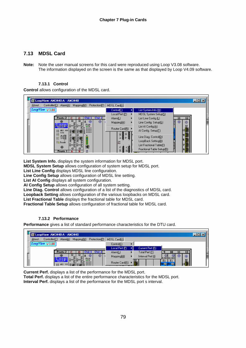
Chapter 7 Plug-in Cards
79
7.13 MDSL Card Note: Note the user manual screens for this card were reproduced using Loop V3.08 software.
The information displayed on the screen is the same as that displayed by Loop V4.09 software.
7.13.1 Control Control allows configuration of the MDSL card. List System Info. displays the system information for MDSL port. MDSL System Setup allows configuration of system setup for MDSL port. List Line Config displays MDSL line configuration. Line Config Setup allows configuration of MDSL line setting. List AI Config displays all system configuration. AI Config Setup allows configuration of all system setting. Line Diag. Control allows configuration of a list of the diagnostics of MDSL card. Loopback Setting allows configuration of the various loopbacks on MDSL card. List Fractional Table displays the fractional table for MDSL card. Fractional Table Setup allows configuration of fractional table for MDSL card.
7.13.2 Performance Performance gives a list of standard performance characteristics for the DTU card. Current Perf. displays a list of the performance for the MDSL port. Total Perf. displays a list of the entire performance characteristics for the MDSL port. Interval Perf. displays a list of the performance for the MDSL port s interval.

Chapter 7 Plug-in Cards
80
7.13.3 Alarm Alarm allows setup and review of the various alarm functions for the MDSL card. Alarm Queue displays a list of the current alarm settings. List Alarm displays the history of the various alarms. Alarm Setup allows configuration of the various alarm settings.
7.13.4 Mapping Mapping provides a menu to view TSI map. Current Slot TSI Map displays the current TSI Map
7.13.5 Router Card Router Card allows configuration of the remote router card. List Unit Route displays unit route information Unit Route Setup allows configure the route setting
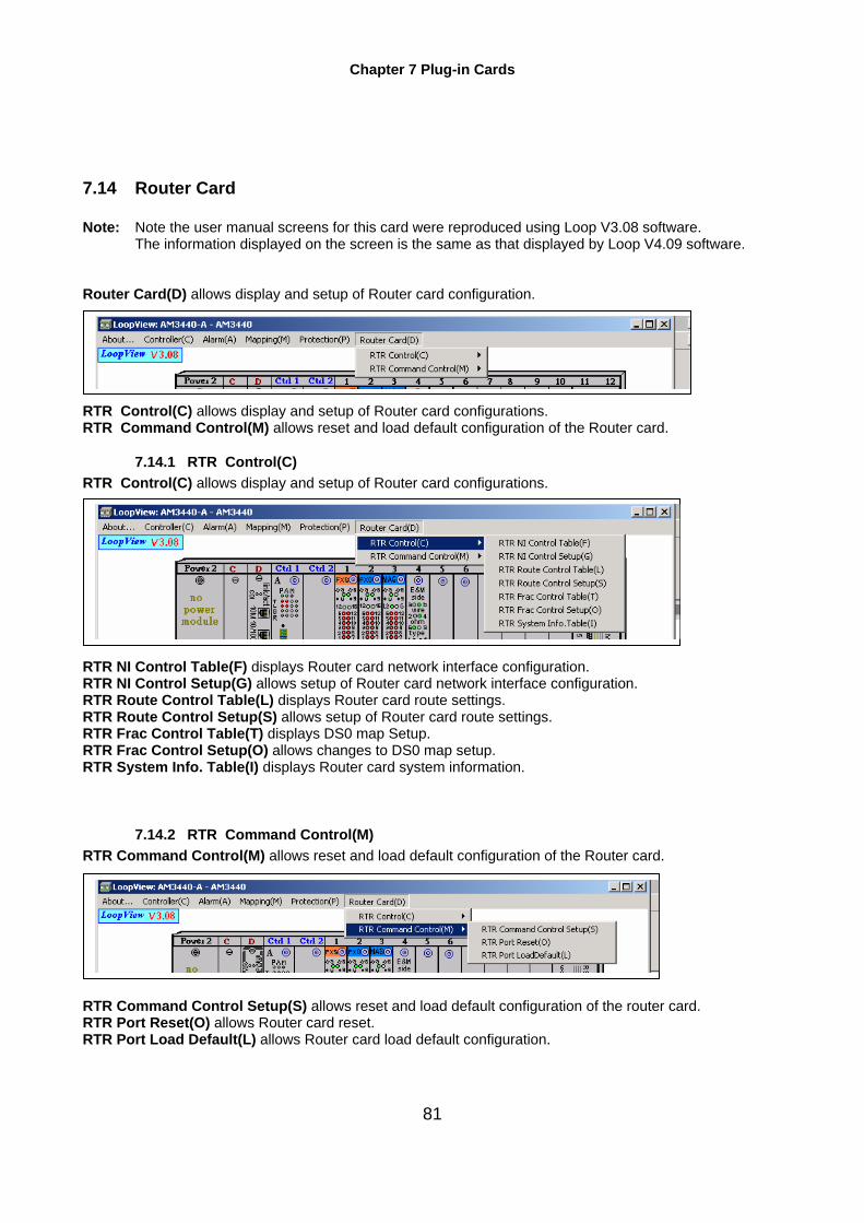
Chapter 7 Plug-in Cards
81
7.14 Router Card Note: Note the user manual screens for this card were reproduced using Loop V3.08 software.
The information displayed on the screen is the same as that displayed by Loop V4.09 software. Router Card(D) allows display and setup of Router card configuration. RTR Control(C) allows display and setup of Router card configurations. RTR Command Control(M) allows reset and load default configuration of the Router card.
7.14.1 RTR Control(C) RTR Control(C) allows display and setup of Router card configurations. RTR NI Control Table(F) displays Router card network interface configuration. RTR NI Control Setup(G) allows setup of Router card network interface configuration. RTR Route Control Table(L) displays Router card route settings. RTR Route Control Setup(S) allows setup of Router card route settings. RTR Frac Control Table(T) displays DS0 map Setup. RTR Frac Control Setup(O) allows changes to DS0 map setup. RTR System Info. Table(I) displays Router card system information.
7.14.2 RTR Command Control(M) RTR Command Control(M) allows reset and load default configuration of the Router card. RTR Command Control Setup(S) allows reset and load default configuration of the router card. RTR Port Reset(O) allows Router card reset. RTR Port Load Default(L) allows Router card load default configuration.

Chapter 7 Plug-in Cards
82
7.15 T1 Card Note: Note the user manual screens for this card were reproduced using Loop V3.08 software.
The information displayed on the screen is the same as that displayed by Loop V4.09 software. T1 Card(T) allows display and configuration of the T1 card settings. Local Control(C) allows configuration of the T1 card. Local Perf.(P) lists performance characteristics for the T1 card. These characteristics can be cleared. Local Alarm(A) allows setup and review of the various alarm functions for the T1 card. Mapping(M) displays current T1 card
7.15.1 Local Control(C) Local Control(C) allows configuration of the T1 card. List Line Control(L) displays the current configuration of the T1 line. Line Control Setup(S) allows setup and configuration of the T1 card. List Line Diagnostic(G) displays the current configuration of the line diagnostic routine. Loopback Setting(B) allows configuration of the loopback settings on the T1 card. T1 system Info.(I) displays T1 system information. List Command Control(M) displays the current configuration for the T1 card’s command settings. Command Control Setup(D) allows configuration of the T1 card’s command settings.
7.15.2 Local Perf.(P) Local Perf.(P) lists performance characteristics for the T1 card. These characteristics can be cleared. User Perf.(U)displays a list of the current user performance information. Line Perf.(L) displays a list of the current user interval performance information.

Chapter 7 Plug-in Cards
83
List Line Availability Perf.(A) displays line availability performance of theT1 card.
7.15.3 Local alarm(A) Local Alarm(A) allows setup and review of the various alarm functions for the T1 card. List Alarm Control(M) displays the current configuration of the various alarms. Alarm Control Setup(S) allows configuration of the various alarm settings. List Threshold(O) displays the configuration of the alarm thresholds. Threshold Setup(T) allows configuration of the alarm thresholds. List Alarm History (H)displays the history of the various alarms. Alarm Queue(Q) displays a list of the current alarm conditions.
7.15.4 Mapping(M) Mapping(M) displays current map o f the T1 card. Current Slot TSI Map(R) displays current map o f the T1 card.

Chapter 7 Plug-in Cards
84
7.16 X.50 Card Note: Note the user manual screens for this card were reproduced using Loop V3.08 software.
The information displayed on the screen is the same as that displayed by Loop V4.09 software. X.50 Card(D) allows setup and display of card functions.
X.50 Control(C) allows display of alarm history and setup of alarm control. X.50 Alarm(A) allows setup and display of alarms. X.50 Diagnostic(D) allows display of diagnostic information and the setup of loopbacks.
7.16.1 X.50 Control(C) X.50 Control(C) allows display of alarm history and setup of alarm control. List X.50 Config.(F) displays card configuration. X.50 Config. Setup(G) allows setup of card configuration. List X.50Control(R) allows reset of the X.50 card. X.50 Control Setup(D) ) allows reset of the X.50 card. List X.50 Status(A) displays per port status. List X.50 Card Info.(I) displays software version of the X.50 card.
7.16.2 X.50 Alarm(A) X.50 Alarm(A) allows setup and display of alarms. X.50 Alarm History(H) displays alarm history. List X.50 Alarm(C) displays alarm configuration. X.50 Alarm Setup(S) allows alarm setup.
7.16.3 X.50 Diagnostic(D) X.50 Diagnostic(D) allows display of diagnostic information and the setup of loopbacks. List X.50 Diagnostic(B) displays X.50 card diagnostic information. X.50 Loopback Setting(L) allows setup up loopbacks.