Embed Size (px)
Citation preview

Int J Comput Vis (2011) 95:13–28DOI 10.1007/s11263-011-0470-y
Looking Around the Corner using Ultrafast Transient Imaging
Ahmed Kirmani · Tyler Hutchison · James Davis ·Ramesh Raskar
Received: 22 May 2010 / Accepted: 23 May 2011 / Published online: 23 June 2011© Springer Science+Business Media, LLC 2011
Abstract We propose a novel framework called transientimaging for image formation and scene understandingthrough impulse illumination and time images. Using time-of-flight cameras and multi-path analysis of global lighttransport, we pioneer new algorithms and systems for sceneunderstanding through time images. We demonstrate thatour proposed transient imaging framework allows us to ac-complish tasks that are well beyond the reach of existingimaging technology. For example, one can infer the geome-try of not only the visible but also the hidden parts of a scene,enabling us to look around corners. Traditional cameras esti-mate intensity per pixel I (x, y). Our transient imaging cam-era captures a 3D time-image I (x, y, t) for each pixel anduses an ultra-short pulse laser for illumination. Emergingtechnologies are supporting cameras with a temporal-profile
The Marr Prize is awarded to the best paper(s) at the biannual flagshipvision conference, the IEEE International Conference on ComputerVision (ICCV). This paper is an extended and re-reviewed journalversion of the conference paper that received Honorable Mention in2009.
Electronic supplementary material The online version of this article(doi:10.1007/s11263-011-0470-y) contains supplementary material,which is available to authorized users.
A. Kirmani (�) · T. Hutchison · R. RaskarMIT Media Lab, Cambridge, MA 02139, USAe-mail: [email protected]
T. Hutchisone-mail: [email protected]
R. Raskare-mail: [email protected]
J. DavisDepartment of Computer Science, UC Santa Cruz, Santa Cruz,CA 95064, USAe-mail: [email protected]
per pixel at picosecond resolution, allowing us to capture anultra-high speed time-image. This time-image contains thetime profile of irradiance incident at a sensor pixel. We ex-perimentally corroborated our theory with free space hard-ware experiments using a femtosecond laser and a picosec-ond accurate sensing device. The ability to infer the structureof hidden scene elements, unobservable by both the cameraand illumination source, will create a range of new computervision opportunities.
Keywords Light transport · Global illumination ·Multi-path analysis · Inverse problems · Inverse rendering ·Computational Imaging
1 Introduction
How can we use time-of-flight cameras for performingmulti-path analysis of global light transport? If so, then howcan this allow the design of new algorithms and systemsfor scene understanding through time images? Can we usesuch a framework for estimating 3D geometry and appear-ance of not only visible but also hidden parts of a scene?We propose a novel theoretical framework for image for-mation and scene understanding using impulse illuminationand time images. We call this framework Transient imaging.We also propose the design of an ultrafast imaging devicebased on this framework which we term as a Transient imag-ing camera. We used our inverse algorithms and measure-ments collected using the transient imaging camera to esti-mate the hidden scene geometry from a fixed single view-point.
The light field or the Plenoptic function describes theamount of light traveling in every direction through everypoint in space at any wavelength at any point in time. It is
14 Int J Comput Vis (2011) 95:13–28
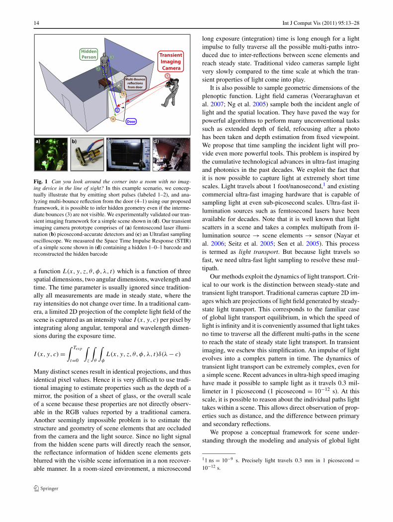
Fig. 1 Can you look around the corner into a room with no imag-ing device in the line of sight? In this example scenario, we concep-tually illustrate that by emitting short pulses (labeled 1–2), and ana-lyzing multi-bounce reflection from the door (4–1) using our proposedframework, it is possible to infer hidden geometry even if the interme-diate bounces (3) are not visible. We experimentally validated our tran-sient imaging framework for a simple scene shown in (d). Our transientimaging camera prototype comprises of (a) femtosecond laser illumi-nation (b) picosecond-accurate detectors and (c) an Ultrafast samplingoscilloscope. We measured the Space Time Impulse Response (STIR)of a simple scene shown in (d) containing a hidden 1–0–1 barcode andreconstructed the hidden barcode
a function L(x, y, z, θ,φ,λ, t) which is a function of threespatial dimensions, two angular dimensions, wavelength andtime. The time parameter is usually ignored since tradition-ally all measurements are made in steady state, where theray intensities do not change over time. In a traditional cam-era, a limited 2D projection of the complete light field of thescene is captured as an intensity value I (x, y, c) per pixel byintegrating along angular, temporal and wavelength dimen-sions during the exposure time.
I (x, y, c) =∫ Texp
t=0
∫z
∫θ
∫φ
L(x, y, z, θ,φ,λ, t)δ(λ − c)
Many distinct scenes result in identical projections, and thusidentical pixel values. Hence it is very difficult to use tradi-tional imaging to estimate properties such as the depth of amirror, the position of a sheet of glass, or the overall scaleof a scene because these properties are not directly observ-able in the RGB values reported by a traditional camera.Another seemingly impossible problem is to estimate thestructure and geometry of scene elements that are occludedfrom the camera and the light source. Since no light signalfrom the hidden scene parts will directly reach the sensor,the reflectance information of hidden scene elements getsblurred with the visible scene information in a non recover-able manner. In a room-sized environment, a microsecond
long exposure (integration) time is long enough for a lightimpulse to fully traverse all the possible multi-paths intro-duced due to inter-reflections between scene elements andreach steady state. Traditional video cameras sample lightvery slowly compared to the time scale at which the tran-sient properties of light come into play.
It is also possible to sample geometric dimensions of theplenoptic function. Light field cameras (Veeraraghavan etal. 2007; Ng et al. 2005) sample both the incident angle oflight and the spatial location. They have paved the way forpowerful algorithms to perform many unconventional taskssuch as extended depth of field, refocusing after a photohas been taken and depth estimation from fixed viewpoint.We propose that time sampling the incident light will pro-vide even more powerful tools. This problem is inspired bythe cumulative technological advances in ultra-fast imagingand photonics in the past decades. We exploit the fact thatit is now possible to capture light at extremely short timescales. Light travels about 1 foot/nanosecond,1 and existingcommercial ultra-fast imaging hardware that is capable ofsampling light at even sub-picosecond scales. Ultra-fast il-lumination sources such as femtosecond lasers have beenavailable for decades. Note that it is well known that lightscatters in a scene and takes a complex multipath from il-lumination source → scene elements → sensor (Nayar etal. 2006; Seitz et al. 2005; Sen et al. 2005). This processis termed as light transport. But because light travels sofast, we need ultra-fast light sampling to resolve these mul-tipath.
Our methods exploit the dynamics of light transport. Crit-ical to our work is the distinction between steady-state andtransient light transport. Traditional cameras capture 2D im-ages which are projections of light field generated by steady-state light transport. This corresponds to the familiar caseof global light transport equilibrium, in which the speed oflight is infinity and it is conveniently assumed that light takesno time to traverse all the different multi-paths in the sceneto reach the state of steady state light transport. In transientimaging, we eschew this simplification. An impulse of lightevolves into a complex pattern in time. The dynamics oftransient light transport can be extremely complex, even fora simple scene. Recent advances in ultra-high speed imaginghave made it possible to sample light as it travels 0.3 mil-limeter in 1 picosecond (1 picosecond = 10−12 s). At thisscale, it is possible to reason about the individual paths lighttakes within a scene. This allows direct observation of prop-erties such as distance, and the difference between primaryand secondary reflections.
We propose a conceptual framework for scene under-standing through the modeling and analysis of global light
11 ns = 10−9 s. Precisely light travels 0.3 mm in 1 picosecond =10−12 s.
Int J Comput Vis (2011) 95:13–28 15
transport using time images. We explore new opportunitiesin multi-path analysis of light transport using time-of-flightsensors. Our approach to scene understanding is four-fold:
1. Measure the scene’s transient photometric response func-tion using the directional time-of-flight camera and activeimpulse illumination.
2. Estimate the structure and geometry of the scene usingthe observed STIR.
3. Use the estimated structure and geometry along withaprior models of surface light scattering properties to in-fer the scene reflectance.
4. Higher order inference engines can be constructed thatuse the estimated scene properties for higher level sceneabstraction and understanding.
Our solution to the problem of single viewpoint lookingaround corners using transient imaging can be summarizedin the pseudo-equation: 2-dimensional single viewpoint pro-jection + 1-dimensional time sampling = 4-dimensionalmultiple viewpoint illumination and sensing.
1.1 Contributions
In this paper, we propose a first, initial approach for solv-ing the hard inverse problem of recovering structure of com-pletely occluded scenes based on transient imaging methodsas opposed to traditional steady state imaging. Our methodinvolves computational processing of time-samples of thelight scattered in response to active, impulsive illuminationof visible parts of the scene. We made the following contri-butions through this paper:
1. Developed a theoretical framework called transient lighttransport that uses time images and impulse illuminationfor scene understanding.
2. We proposed a transient imaging camera model whichtime samples incident light continuously and uses spatio-temporal impulse illumination as the light source.
3. We built a proof-of-concept hardware prototype compris-ing a femtosecond laser and a directionally sensitive, pi-cosecond accurate photo sensor array, intensified CCDcameras and picosecond streak cameras to demonstratethe practical use of transient imaging theory. Using ourprototype, we demonstrated all the key functionalitiesrequired in an imaging device: geometry, photometry,multi-bounce (multi-path) light separation and free-spacefunctioning.
4. We also demonstrated how our proposed imaging modelenables novel scene understanding which allows us tolook around the corner without any device in the line ofsight. In particular, we reconstruct the structure and ge-ometry of hidden planar scenes using our transient imag-ing theory and camera prototype. We have verified thisthrough both simulation and experiments.
2 Related Work
Transient imaging is a new imaging domain. To our bestknowledge, neither the transient light transport theory northe presented imaging experiments have ever been con-ceived in literature. The basic differences between transientimaging and related imaging methods are summarized next.Also see Fig. 2 for a quick comparison and discussion oftransient imaging with other popular imaging methods.
2.1 Theoretical Prior Art
Global Light Transport Light often follows a complexpath between the emitter and sensor. A description ofsteady-state light transport in a scene is referred to as therendering equation (Kajiya 1986). Extensions have beendescribed to include time in light transport (Arvo 1993).In Raskar and Davis (2007) proposed inverse analysis us-ing a 5D time-light transport matrix to recover geometricand photometric scene parameters. In addition, Smith et al.(2008) proposed a modification of the rendering equationvia a transient rendering framework. Accurate measurementof physical scene properties is called inverse-rendering (Pa-tow and Pueyo 2003). Complex models have been developedfor reconstructing specular (Kutulakos and Steger 2007),transparent (Morris and Kutulakos 2007), Lambertian (Na-yar et al. 1990) scenes and joint lighting and reflectance (Ra-mamoorthi and Hanrahan 2001).
Capturing and Analysis of Light Transport Recent workin image-based modeling and computational photographyhas also shown several methods for capturing steady-statelight transport (Sen et al. 2005). The incident illuminationis represented as a 4D illumination field and the resultantradiance is represented as a 4D view field. Taken together,the 8D reflectance field represents all time-invariant interac-tion of a scene. Our work is influenced by the following pio-neering efforts in steady-state global light transport analysis.Nayar et al. decomposed an image into its direct and indi-rect components under the assumption that the scene has nohigh-frequency components (Nayar et al. 2006). Seitz et al.(2005) have decomposed images into multi-bounce compo-nents under the assumption that the scene is Lambertian. Al-though the dual photography approach (Sen et al. 2005) cansee an object hidden from a camera, it requires a projectorin the object’s line of sight. Our method exploits transient,rather than steady-state transport, to estimate more challeng-ing scene properties.
2.2 Hardware and Experimental Prior Art
SONAR (SOund Navigation And Ranging), is a techniquethat uses sound propagation in a medium such as air or wa-ter to detect and locate remote objects. The speed of sound

16 Int J Comput Vis (2011) 95:13–28
Fig. 2 Popular imagingmethods plotted in theSpace-Angle-Time axes. Withhigher dimensional lightcapture, we expand the horizonsof scene understanding. ALIDAR generates 2D image, butunlike a time gated camera, it isessentially a 1D (time/range)sensor, and image is generatedby scanning. Our concepttransient imaging camera shownin Fig. 6 uses LIDAR-likeimaging hardware, but, incontrast, we exploit themulti-path information which isrejected in both LIDAR (LIghtDetection And Ranging) andOCT (Optical coherencetomography). A phased array(antenna) an angle relateddevice—but unlike thewave-front sensor that is usedfor measuring angles, a phasedarray is usually combined, forexample with a pulse radar. Notethat the phase here is a functionof both the beam steering duringtransmission and the angularsensitivity during reception.Note that this figure mixes timeand frequency in one axis.Additionally, many phase arraysalso work at gigahertz range
is six orders of magnitude slower than the speed of light, andtherefore easier to detect. Nevertheless work in SONAR hasproduced intricate models of the effects of many surfaceswith complicated scattering properties. In addition, detec-tion over the corner as well as exploiting multi-path in thecontext of Over the Horizon RADAR, and Synthetic Aper-ture RADAR have been demonstrated before (Garren et al.2004, 2005; Sarunic et al. 2001).
LIDAR (LIght Detection And Ranging) systems modulatelight, typically on the order of nanoseconds, and measure thephase of the reflected signal to determine depth (Kamerman1993). Flash LIDAR systems use a 2D imager to provide fastmeasurement of full depth maps (Iddan and Yahav 2001;Lange and Seitz 2001). Importantly, a number of com-panies (Canesta http://canesta.com/; MESA http://www.mesa-imaging.ch/; 3DV http://www.3dvsystems.com/; PMDhttp://www.pmdtec.com/) are pushing this technology to-wards consumer price points. The quality of phase esti-mation can be improved by simulating the expected shapeof the reflected signal or estimating the effect of ambient
light (Gonzalez-Banos and Davis 2004). Separately detect-ing multiple peaks in the sensor response can allow twosurfaces, such as a forest canopy and a ground plane, to bedetected, and waveform analysis can detect surface discon-tinuities (Vandapel et al. 2004).
LIDAR systems have been successful in some circum-stances, but they work well only for certain types of sur-face reflectance, and do little to help estimate other globalproperties such as relationship between scene patches. Inaddition they are used in restrictive configurations by care-fully placing emitters near the receivers. We need a gener-alized sensor which fundamentally records a greater portionof the light transport in a scene. This sensor could then beused to design new algorithms and specialized sensing meth-ods.
Time-gated imaging captures a gated image, I (x, y, tδ), byintegrating the reflected pulse of light over extremely shortwindows. Multiple captures at incremental time windows,tδ , allow the time image I (x, y, t) to be captured at up to100 picosecond accuracy. Nanosecond windows are used for

Int J Comput Vis (2011) 95:13–28 17
imaging tanks at the range of kilometers and picosecond gat-ing allows imaging in turbid water. It is possible to constructthe transient photometric response function using gated im-agers, e.g. Busck et. al show a TPRF measured to 100 pi-cosecond accuracy.
Streak cameras Streak cameras are ultrafast photonicrecorders which deposit photons across a spatial dimen-sion, rather than integrating them in a single pixel. Usinga 2D array, I (x, yδ, t) can be measured. Sweeping the fixeddirection, yδ , allows I (x, y, t) to be captured. Picosecondstreak cameras have been available for decades (Campilloand Shapiro 1983). Modern research systems can functionin the attosecond range (Itatani et al. 2002).
Femtosecond Imaging Optical coherence tomography(OCT) (Schmitt 1999), an interferometric technique, andtwo-photon microscopy (Denk et al. 1990), using fluores-cence, allow high-quality, micrometer resolution 3D imag-ing of biological tissue. Both these methods are based onpulsed femtosecond illumination. Femtosecond windowsalso allow ballistic photons to be separated from scatteredphotons while imaging in biological tissue. Experiments inthis paper are the first attempt at free-space use of femto-laser illumination in contrast to their established use in opti-cal fibers or millimeter-scale biological samples. All the ex-isting methods based on time sampling of light make no useof global light transport reasoning to infer scene character-istics. They image in a single direction time-gated windowto improve SNR and reject multi-path scattering. This papershows that complex global reasoning about scene content ispossible given a measured multi-path time profile.
3 Transient Imaging Framework
In our transient light transport framework, we assume thatthe speed of light is some finite value and light takes a finiteamount of time to travel from one scene point to the other.As light scatters around a scene, it takes different paths, andlonger paths take a longer time to traverse. Even a singlepulse of light can evolve into a complicated pattern in time.The dynamics of transient light transport can be extremelycomplex, even for a simple scene. The theory of light trans-port describes the interaction of light rays with a scene. Inci-dent illumination provides first set of light rays that travel to-wards other elements in the scene and the camera. The directbounce is followed by a complex pattern of inter-reflectionswhose dynamics is governed by the scene geometry and ma-terial properties of the scene elements. This process contin-ues until an equilibrium light flow is attained.
We consider a scene S (Fig. 3) composed of M smallplanar facets (patches with unit area) p1, . . . pM with ge-ometry G = {Z,D,N,V } comprising of the patch positions
Fig. 3 A scene consisting of M = 5 patches and the illumina-tion-camera patch p0. The patches have different spatial coordinates(zx
i , zyi , zz
i ), orientations ni and relative visibility between patches vij .The patches also have different material properties, for instance p4 isdiffused, p4 is translucent and p5 is a mirror
Z = [z1, . . . , zM ] where each zi ∈ R3; the distance matrix
D = [dij ] where dij = dji is the Euclidean distance be-tween patches pi and pj ; the relative orientation matrixN = [n1, . . . , ˆnM ] consists of unit surface normal vectorsni ∈ R
3 at patch pi with respect to a fixed coordinate sys-tem; and the visibility matrix V = [vij ] where vij = vji = 0or 1 depending on whether or not patch pi is occluded frompj . For analytical convenience, we consider the camera (ob-server) and illumination (source) as a single patch denotedby p0. All the analysis that follows can be generalized toinclude multiple sources and the observer at an arbitrary po-sition in the scene.
We introduce a variation of the rendering equation (Ka-jiya 1986; Immel et al. 1986) in which we represent the timelight takes to traverse distances within the scene by a finitedelay. Let t denote a time instant and {Lij : i, j = 0, . . . ,M}be the set of radiances for rays that travel between scenepatches. Transient light transport is governed by the follow-ing dynamical equation which we term as transient lighttransport equation:
Lij [t] = Eij [t] +M∑
k=0
fkijLki[t − δki] (1)
Equation (1) states that the scalar ray radiance Lij [t] leav-ing patch pi towards pj at time t is the sum of emissive ra-diance Eij [t] and the form factor weighted delay sum of theradiances from other patches. For simplicity, let the speedof light c = 1. Then the propagation delay δij is equal tothe distance dij (see Fig. 5). We assume that all delays δij
are integer multiples of a unit delay. The scalar weights fkij
or form factors denote the proportion of light incident from

18 Int J Comput Vis (2011) 95:13–28
Fig. 4 Form factors fkij are the proportion of light incident from patchpk on to pi that will be directed towards pj
Fig. 5 A ray impulse E02[t] directed towards patch p2 at time t . Thisray illuminates p2 at time instant t + δ02 and generates the directionalradiance vector [L20[t + δ],L21[t],L23[t]]. These light rays travel to-wards the camera p0 and scene patches p1 and p3 resulting in globalillumination
patch pk on to pi that will be directed towards pj :
fkij = ρkij
(cos(θin) cos(θout )
‖zi − zj‖2vkivij
)
where ρkij is the directional reflectance which dependson the material property and obeys Helmholtz reciprocity(ρkij = ρjik), θin is the incident angle and θout is the view-ing angle (see Fig. 4). Additionally, if the patch does notinteract with itself and then fkij = 0 for k = i or i = j . Weassume that the scene is static and material properties areconstant over the imaging interval. The source and observerpatch p0 does not participate in inter-reflections.
We model illumination using the emitter patch p0. Allother patches in the scene are non-emissive, Eij [t] = 0 : i =1, . . . ,M ; j = 0, . . . ,M ; t = 0, . . . ,∞. Illumination is theset of radiances {E0j [t] : ∀j = 1, . . . ,M ; t = 0, . . . ,∞} rep-resenting the light emitted towards all scene patches at dif-ferent time instants. The outgoing light at patch pi is thevector of directional radiances,
L[i, t] = [Li0[t], . . . ,LiM [t]]and for the entire scene we have the transient light trans-port vector L[t] = [L[1, t], . . . ,L[M, t]] which contains(M(M − 1) + M) scalar irradiances. We can only observethe projection of L[t] that is directed towards the camerap0. At each time t we record a vector of M intensity valuesLc[t] = [L10[t − δ10], . . . ,LM0[t − δM0]]T .
Fig. 6 Transient Imaging Camera captures a 3D time image in re-sponse to a ray impulse illumination
3.1 Transient Imaging Camera
The transient imaging camera model comprises a general-ized sensor and a pulsed illumination source. Each sensorpixel observes a unique patch in the scene. It also continu-ously time samples the incoming irradiance, creating a 3Dtime image, I (xi, yi, t) (see Fig. 6. The pixel at sensor po-sition (xi, yi) observes the patch pi over time. The pulsedillumination source generates arbitrarily short duration anddirectional impulse rays. The direction of an impulse rayaimed at patch pi is specified by (θi, φi ). The sensor andillumination are synchronized for precise measurement ofTime Difference Of Arrival (TDOA).
3.2 Space Time Impulse Response
The Space Time Impulse Response or the STIR of a sceneS denoted by STIR(S) is a collection of time images, eachcaptured with an impulse ray aimed the direction (θj ,φj ),illuminating a single scene patch pj . This is a 5D func-tion: STIR(xi, yi, θj , φj , t). We measure the STIR as fol-lows (see Fig. 7):
1. For each patch pj : j = 1, . . . ,M .2. Illuminate pj with an impulse ray (θj ,φj ).3. Record time image {I (xi, yi, t) : i = 1 . . .M; t =
0 . . . T } = STIR(xi, yi, θj , φj , t).
In still scenes with static material properties, transientlight transport is a Linear and Time Invariant (LTI) process.By linear, we imply that if we illuminate the scene as justdescribed and record the STIR but with a different scalarmultiple of the illumination intensity, then the received in-tensities that comprise the STIR will also be scaled with thesame scalar multiple. By linearity, we also imply that thetime-image that is received in response to simultaneous im-pulse illumination of two patches, say, pi and pj , is equalto the sum of the individual time-images, I (xi, yi, t) and
Int J Comput Vis (2011) 95:13–28 19
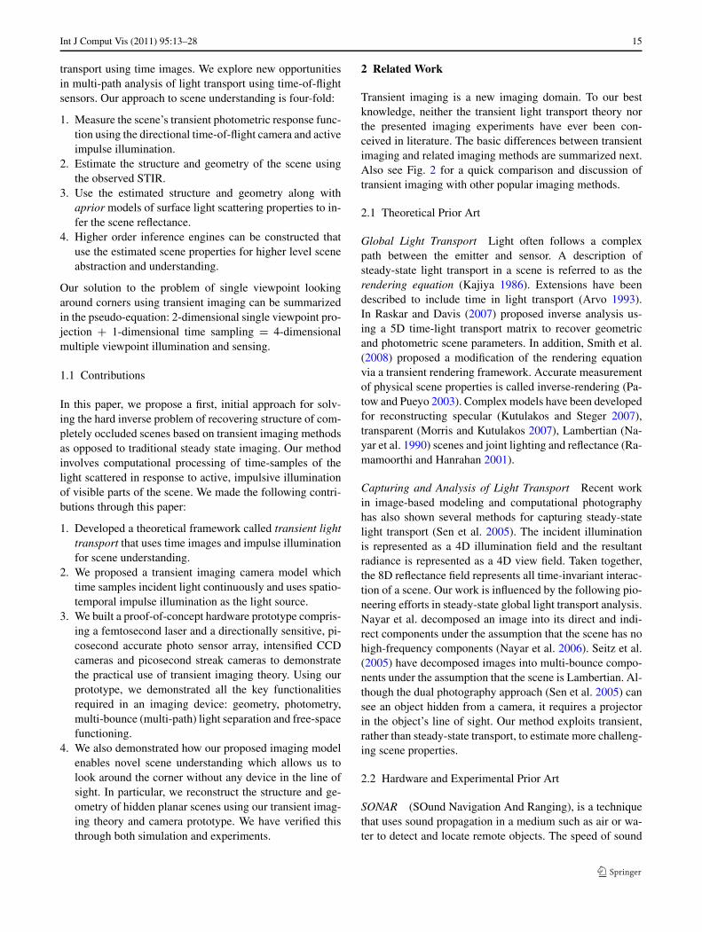
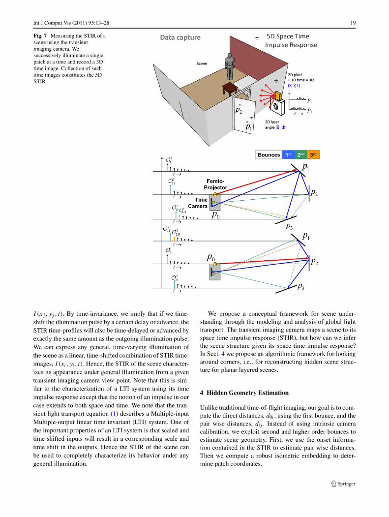
Fig. 7 Measuring the STIR of ascene using the transientimaging camera. Wesuccessively illuminate a singlepatch at a time and record a 3Dtime image. Collection of suchtime images constitutes the 5DSTIR
I (xj , yj , t). By time-invariance, we imply that if we time-shift the illumination pulse by a certain delay or advance, theSTIR time-profiles will also be time-delayed or advanced byexactly the same amount as the outgoing illumination pulse.We can express any general, time-varying illumination ofthe scene as a linear, time-shifted combination of STIR time-images, I (xi, yi, t). Hence, the STIR of the scene character-izes its appearance under general illumination from a giventransient imaging camera view-point. Note that this is sim-ilar to the characterization of a LTI system using its timeimpulse response except that the notion of an impulse in ourcase extends to both space and time. We note that the tran-sient light transport equation (1) describes a Multiple-inputMultiple-output linear time invariant (LTI) system. One ofthe important properties of an LTI system is that scaled andtime shifted inputs will result in a corresponding scale andtime shift in the outputs. Hence the STIR of the scene canbe used to completely characterize its behavior under anygeneral illumination.
We propose a conceptual framework for scene under-standing through the modeling and analysis of global lighttransport. The transient imaging camera maps a scene to itsspace time impulse response (STIR), but how can we inferthe scene structure given its space time impulse response?In Sect. 4 we propose an algorithmic framework for lookingaround corners, i.e., for reconstructing hidden scene struc-ture for planar layered scenes.
4 Hidden Geometry Estimation
Unlike traditional time-of-flight imaging, our goal is to com-pute the direct distances, d0i , using the first bounce, and thepair wise distances, dij . Instead of using intrinsic cameracalibration, we exploit second and higher order bounces toestimate scene geometry. First, we use the onset informa-tion contained in the STIR to estimate pair wise distances.Then we compute a robust isometric embedding to deter-mine patch coordinates.

20 Int J Comput Vis (2011) 95:13–28
4.1 Inverse Geometry Problem
We develop our formulation for a scene with the followingstrict assumptions:
1. Each patch is visible from all the other patches (vij = 1,
∀i, j ). We also assume that there are no limiting cases inwhich the incoming illumination direction is perpendic-ular to the surface normal.
2. The reflectance of each patch pi has a non-zero diffusecomponent. This assumption ensures that we are ableto estimate direct distances d0i . In particular, when anypatch is illuminated from any direction it scatters a non-zero amount of light towards all other patches.
In Sect. 4.1, we discuss the extension of our transientimaging framework to scenes consisting of patches hiddenfrom the camera and illumination.
Distances from STIR Define O1 = {O1i |i = 1, . . . ,M} as
the set of first onsets: the collection of all time instants, O1i ,
when the pixel observing patch pi receives the first non-zero response while the source illuminates the same patchpi (Fig. 7). O1
i is the time taken by the impulse ray originat-ing at p0 directed towards pi to arrive back at p0 after thefirst bounce; this corresponds to the direct path p0 → pi →p0. Similarly, we define O2 = {O2
ij |i, j = 1, . . . ,M; j �= i}as the set of second onsets: the collection of times whenthe transient imaging camera receives the first non-zero re-sponse from a patch pi while illuminating a different patchpj (Fig. 7). This corresponds to the multi-path p0 → pj →pi → p0. O2
ij = O2ji . It is straightforward to label the onsets
in O1 and O2 because they correspond to the first non-zeroresponses in STIR time images.
In order to compute D using O1 and O2, we constructthe forward distance transform, T2 which models the sumof appropriate combinations of path lengths contained in thedistance vector d = vec(D) and relates it to the vector ofobserved onsets O. Then we solve the linear system T2d =O to obtain distance estimates d. As an example, consider ascene with 3 patches (M = 3) as shown in Fig. 7. The linearsystem for this scene is constructed as:
⎡⎢⎢⎢⎢⎢⎢⎢⎣
2 0 0 0 0 01 1 0 1 0 01 0 1 0 0 1
0 0 0 0 2 00 0 0 1 1 1
0 0 0 0 0 2
⎤⎥⎥⎥⎥⎥⎥⎥⎦
⎡⎢⎢⎢⎢⎢⎢⎢⎣
d01
d12
d13
d02
d23
d03
⎤⎥⎥⎥⎥⎥⎥⎥⎦
= c
⎡⎢⎢⎢⎢⎢⎢⎢⎣
O11
O212
O213
O21
O223
O31
⎤⎥⎥⎥⎥⎥⎥⎥⎦
For any M , matrix T2 is full rank and well-conditioned. Dueto synchronization errors, device delays and response timesthe observed onsets have measurement uncertainties which
introduce errors in distance estimates. We use the redun-dancy in second onset values (O2
ij = O2ji) to obtain multiple
estimates, d, and reduce error by averaging them.
Structure from Pairwise Distances The problem of esti-mating scene structure, Z, from pair wise distance esti-mates, D, is equivalent to finding an isometric embeddingZ ⊂ R
M×3 → R3 (Algorithm 1, Dattorro 2006). For com-
putational convenience we take p0 to be the origin (z0 =(0,0,0)). A computer simulation that recovers the scenestructure from noisy distance estimates using the isometricembedding algorithm is shown in Fig. 8. We used the es-timated coordinates, Z, iteratively to recompute robust dis-tance estimates. The use of convex optimization to computeoptimal embeddings in the presence of distance uncertain-ties is explained in (Dattorro 2006).
Algorithm 1 ISOEMBED [D]1. Compute hij = 1
2 (d20i + d2
0j − d2ij ). Construct Gram
matrix HM×M = [hij ]2. Compute the SVD of H = U�V T
3. Pick 3 largest eigenvalue-vectors �3×33 ,UM×3
3 ,V 3×M3
4. Compute embedding Ze = (�3)1/2
V3
5. Rotate and translate to align Z = RZe + T
Scenes with Occluders We now consider a scene that con-tains a set of patches (say H ) hidden from both the cameraand the source. Hidden surface estimation is viewed as twosub-problems:
1. Labeling third onsets.2. Inferring distances to hidden patches from integrated
path lengths.
To estimate the structures of the hidden patches, we makethe following three strong assumptions:
1. The number of hidden patches is known or assumed.2. All third bounces arrive before fourth and higher order
bounces.3. No two or more distinct third bounces arrive at the same
time in the same time profile STIR(xi, yi, θj , φj , t =0 . . . T ).
The second assumption is true for scenes that have nointer-reflection amongst hidden patches. The third assump-tion is generally valid because we measure the STIR onepatch at a time. If a patch, pi , is hidden from p0, then thefirst and second onsets involving pi cannot be observed, i.ethe vector of distances dH = [dij ] : pi ∈ H,j = 0, . . . ,M
cannot be estimated using just O1 and O2. Hence, we needto consider the set of third onsets, O3 = {O3
ijk : i, j, k =

Int J Comput Vis (2011) 95:13–28 21
Fig. 8 (a) Estimating distancesin an all-visible scenecomprising of 3 rectangleswhich are discretized as 49patches. Note that reflectance isnot relevant. (b) Originalgeometry shows the surfacenormals in green. (c) We usednoisy 1st and 2nd time onsets(Gaussian noise ∼ N (μ,σ 2),μ = device resolution = 250 psand σ = 0.1) to estimate thedistances using the T2 operator(inset shows enlarged view).(d) This is followed byisometric embedding andsurface fitting. Thereconstruction errors are plotted.Color bar shows %-error inreconstructed coordinate values
1, . . . ,M; i �= j ; j �= k}, that corresponds to third bounces.Note that there are O(M) first onsets, O(M2) second on-sets and O(M3) third onsets. Also, Euclidean geometry im-poses that O3
ijk = O3kji . Labeling the onsets contained in
O3 is non-trivial. An important generalization of the hid-den patches scenario is to estimate distances in the case ofmultiple interactions between hidden patches. If a hiddenpatch has at most N inter-reflections with the other hiddenpatches, then we need to utilize onsets that correspond to upto (N + 3) bounces i.e. the sets O1, O2, . . . , ON+3.
As a simple example, consider the scene in Fig. 9. As-sume that the patches p2 and p3 are hidden. We first com-pute the distances involving visible patches, d01, d04, d14
as explained in Sect. 4.1. The distances (d21, d24) and(d31, d34) are not directly observable. Once these distancesare estimated, d02, d03 and d23 can be computed using multi-lateration. Now, we apply our labeling algorithm to identifythird onsets. The onsets, O3
141 and O3414, are readily labeled
using TDOA, since we know the distances to patch p1 andp4. The onsets O3
121, O3131, O3
424, O3434, O3
124, O3134, O3
421,O3
431 are disambiguated using the facts that O3421 = O3
124,O3
431 = O3134 and the onsets arrive in different time pro-
files of the STIR(S). We sort the remaining onsets basedon their arrival times and label them based on the a pri-ori assumption of the proximity of hidden patches to visi-ble patches. In this example, w.l.o.g. we assume that p2 iscloser to p1 than p3. Hence, the onset O3
121 arrives ear-lier than O3
131 (see onset arrival profile in Fig. 9). Thislabeling procedure can be generalized for multiple hiddenpatches:
1. Estimate the distances to all the visible scene patches(Sect. 4.1) and use the arrival times to label all thirdbounce onsets corresponding to visible geometry.
2. Fix an arbitrary ordering of hidden patches based on theirproximity to some visible patch.
3. Use arrival times to identify the third onset pairs corre-sponding to same path length (O3
ijk = O3kji ). Label them
with the ordering of step 2.4. Sort the remaining onsets according to their arrival times
and use step 2 ordering to label them.
We construct the distance operator, T3, that relates thirdbounces arrival times involving hidden patches, OH , and thedistances to the hidden patches, dH . We solve the resultinglinear system T3dH = OH and obtain the complete distanceset, D. We then estimate the structure, Z, as discussed inSect. 4.1. An example of reconstructing hidden 3D geometryis shown in Fig. 10.
⎡⎢⎢⎢⎣
2 0 0 01 1 0 0
0 0 2 00 0 1 1
⎤⎥⎥⎥⎦
⎡⎢⎢⎢⎣
d21
d24
d31
d34
⎤⎥⎥⎥⎦ = c
⎡⎢⎢⎢⎣
O3121 − O1
1O2
124 − (O11 + O1
4 )/2
O3131 − O1
3O2
134 − (O11 + O1
4 )/2
⎤⎥⎥⎥⎦
5 Hardware Prototype and Experiments
5.1 Transient Imaging Camera Prototype
The framework developed in Sect. 4.1 was corroboratedwith experiments conducted using a prototype transient

22 Int J Comput Vis (2011) 95:13–28
Fig. 9 (Color online) A scenewith M = 4 patches. Patches p2and p3 are hidden. The blue(first) and green (second) onsetsare a result of directly observingvisible patches p1 and p4. Thepattern of arrival of third onsetsdepends on the relative distanceof the hidden patches p2 and p3from the visible patches. Theonsets that correspond to lighttraversing the same Euclideandistance are readily identified.Once the onsets are labeled,they are used to obtain distancesthat involve hidden patches
Fig. 10 (a) Estimatingdistances in scenes with hiddenpatches. Unknown to theestimation algorithm, the hiddenpatches are on a plane (shown inblack). (b) Original patchgeometry. We use 1st, 2nd and3rd bounce onsets, our labelingalgorithm and the T3 operator(c) to estimate hidden geometry.(d) The isometric embeddingerror plot verifies negligiblereconstruction error and nearco-planarity of patches. Onsetnoise and color bar schemes aresame as Fig. 8
imaging camera. We demonstrated the feasibility with proofof concept experiments but not a full-fledged imaging ap-paratus. In particular, this prototype (Fig. 1) was developedwith the intent to show that it is feasible to reason aboutmulti-bounce global transport using the STIR.
A commercially-available reverse-biased silicon photosensor (Thorlabs FDS02, $72) was used as the ultrafast sen-sor. This sensor has an active area of 250 microns in diam-eter and a condensing lens to gather more light. A 5 GHzultrafast oscilloscope digitized the photo-currents. The leastcount was 50 ps (1.5 cm light travel). The ray impulse sourcewas a mode locked Ti-Sapphire laser with a center wave-length of 810 nm, that emitted 50 femtosecond long pulsesat a repetition rate of 93.68 MHz. The spatial bandwidth ofthese pulses greatly exceeds the response bandwidth of thesensor. The average laser power was 420 milliwatts, corre-sponding to a peak power of greater than 85 kW.
We were required to sample the incident light with pi-cosecond resolution and be highly sensitive to a low pho-
ton arrival rate. Our depth resolution is limited by the re-sponse time of the detector and digitizer (250 ps, 7.5 cmlight travel). The high peak power of our laser was criticalfor registering SNR above the dark current of our photo sen-sor. Also, our STIR acquisition times are in nanoseconds,which allows us to take a large number of exposures andtime average them to reduce Gaussian noise. In absence of a2D photo sensor array, we emulated directionality by rasterscanning the scene with a steerable laser and sensor.
Four proof-of-concept experiments (Fig. 11) were con-ducted in flatland (2D) to demonstrate the following keyproperties of a transient imaging camera: free space func-tioning, linearity, multi-path light collection, inverse squareintensity falloff and time invariance. Synchronization wasachieved by triggering our pulses based on a reference photosensor. A small part of the laser pulse was deflected into areference photo sensor using a semi-reflective glass patchand all pulse arrivals (onsets) were measured as TDOA withrespect to the reference pulse.

Int J Comput Vis (2011) 95:13–28 23
Fig
.11
Des
ign
and
Veri
ficat
ion
ofa
Tran
sien
tIm
agin
gC
amer
a.(a
)T
hera
yim
puls
esar
ere
cord
edaf
ter
bein
gat
tenu
ated
bya
vary
ing
neut
ral
dens
ityfil
ter.
The
peak
puls
ein
tens
ityde
crea
ses
linea
rly
with
the
atte
nuat
ion.
(b)
The
inte
nsity
ofth
efir
stbo
unce
from
adi
ffus
erob
eys
the
inve
rse
squa
refa
ll-of
fpa
ttern
.(c)
We
are
able
tore
cord
puls
ein
tens
ities
that
are
disc
erni
ble
from
the
nois
eflo
orev
enaf
ter
the
ray
impu
lse
has
been
refle
cted
byth
ree
(2di
ffus
ean
d1
spec
ular
)pa
tche
s.T
hetim
esh
ifts
are
linea
rly
prop
ortio
nalt
oth
em
ulti-
path
leng
th

24 Int J Comput Vis (2011) 95:13–28
5.2 Hidden Geometry Reconstruction Experiments
The transient imaging prototype was used along with thealgorithmic framework developed in Sect. 4.1 to estimategeometry for objects that do not reflect any light to cameradue to specularity or occlusion.
Missing direct reflection Consider the example shown inFig. 12 (top) comprising a mirror and a diffuser. In tra-ditional cameras it is difficult to estimate the distance toa specular surface because there is no direct reflection re-ceived at the camera. Using transient imaging analysis, es-timated the distances to specular surfaces by observing in-direct bounces. If we aim the laser, L, towards a mirror (ina known direction) it will strike an unknown point on M .The reflected light will then illuminate points on the diffuser.Separately, the position and the depth of the diffuser, x, wasestimated via stereo triangulation (using the known angle ofthe laser beam) or ToF (Sect. 4.1). When the laser illumi-nates M , the total path length sensed at a pixel observingD is (z + y + x). Since x is known, the point M is ob-tained using conic multilateration. Note that, in dual pho-tography (Sen et al. 2005), we create the dual image, i.e.the projector view, but that does not allow 3D estimation.We conducted 3 raster scans and assumed z1 = z2 = z3 = z.The path lengths zi + xi + yi , i = 1,2,3 were estimated us-ing TDOA. In this experiment, we incurred a position errorof 1.1662 cm and a maximum distance error of 7.14% incoordinate reconstruction by multilateration.
Looking Around the Corner We demonstrated an exam-ple of multi-path analysis in a scene that contains patcheswhich were not visible to either the camera or the illumina-tion source. Consider the ray diagram shown in Fig. 12 (seebottom row). Only light rays that have first bounced off thediffuser reach the hidden patches P1, P2, P3. Light that isreflected from the hidden patches (second bounce) can onlyreach the camera once it is reflected off the diffuser again(third bounce). The position and depth of the points on thediffuser were estimated using first bounce onsets. We thenraster scanned across the diffuser and measured the time dif-ference of arrival (TDOA) between the first and third bounceonsets. We imaged a hidden 1–0–1 barcode using the firstand third bounces off of a single diffuser. We used sensors,S1 and S2, and a femtosecond laser source, L, neither ofwhich had the barcode in their line of sight. The patches P1
and P3 were ground mirrors and P2 was free space. The mir-rors were aligned to maximize the SNR required for regis-tering a third bounce. The maximum separation between P1
and P3 was limited to 5 cm because of SNR considerations.The first bounce, LD1S1, was recorded by S1, and the twothird bounces from the hidden patches, LD1P1D4S2 andLD1P3D3S2, arrived at S2 within 200 ps of each other. Our
current sensor was not fast enough and could only recordthe sum of the two third bounces. The two bounces can berecorded more accurately with a faster picosecond sensor orseparated using deconvolution using S2’s impulse response.As a proof of concept, we computed a high quality estimateby blocking P1 and P3, one at a time. The reconstruction re-sults are shown in Fig. 12 (bottom). We incurred a maximumerror of 0.9574 cm in coordinate reconstruction.
6 Limitations
Transient imaging is in a preliminary stage of theoreticalmodeling and experimentation. Our work, as it stands, hasseveral limitations which make it challenging to general-ize the transient imaging method to more complex, generalscenes.
6.1 Theoretical Limitations
Fundamentally, transient imaging is an inverse problem. Aswith all inverse problems, there are inherent issues related torobustness and success rate. The inverse light transport prob-lems posed in Sect. 4.1 have degenerate cases in which mul-tiple solutions (scenes) exist for the same observable STIR.In the looking around corner scenario, we make two strongassumptions on the hidden scene geometry which are limit-ing: we assume that the number of hidden patches is known,and that the of order of times-of-arrival of the onsets is pre-served. Also, there is no proof for the uniqueness of our pro-posed solution or for the feasibility and scalability of ourapproach to more complex scenes, such as ones with oc-clusions and nonlinear geometry which causes hidden sceneinter-reflections.
Some of these issues can be alleviated with the use ofsuitable prior models for scene geometry. The resultingparameter estimation problems may be solved using opti-mization based regularization schemes and robustness con-straints. But it may still not be possible to guarantee 100%accuracy while using transient methods. Importantly, al-though our additional time-domain data is noisy, it still re-stricts the class of solutions to a greater extent than using themore limited data of traditional cameras.
Novel noise models for the transient imaging camera arerequired to account for uncertainties due to light-matter in-terplay. If two or more scene patches are occluded fromeach other (vij = 0, i, j �= 0), our theoretical model fails.This problem is circumvented by using our transient imag-ing framework locally, with a subset of scene patches thatsatisfy our assumptions. The number of STIR measurementsgrow polynomially with number of patches, but the onset la-beling complexity is exponential in the number of bounceorders used for inversion. Our framework will benefit from

Int J Comput Vis (2011) 95:13–28 25
Fig
.12
Mis
sing
dire
ctre
flect
ion
(top
):(a
)A
phot
oof
the
setu
p.(b
)R
aydi
agra
mde
scri
bing
the
light
puls
epa
thin
3ra
ster
scan
s.(c
)Pl
otsh
owin
gm
ultil
ater
atio
nus
ing
the
3ra
ster
scan
sda
ta:
orig
inal
and
reco
nstr
ucte
dsc
ene
geom
etri
es.(
d)O
scill
osco
peda
tapl
otsh
owin
gth
eT
DO
Abe
twee
nth
e2n
dbo
unce
and
the
refe
renc
esi
gnal
.Loo
king
arou
ndth
eco
rner
(bot
tom
):(a
)A
phot
oof
the
setu
psh
owin
ghi
dden
1–0–
1ba
rcod
e.T
hese
nsor
san
dth
ela
ser
are
com
plet
ely
shie
lded
from
the
barc
ode.
(b)
Ray
diag
ram
trac
ing
the
path
sof
1sta
nd3r
dbo
unce
sin
the
2ra
ster
scan
s.(c
)Pl
otsh
owin
gth
esc
ene
geom
etry
reco
nstr
ucte
dus
ing
mul
tilat
erat
ion.
(d)
Osc
illos
cope
data
plot
show
ing
the
1stb
ounc
ean
dth
etw
ose
para
tely
reco
rded
3rd
boun
ces,
for
both
rast
ersc
ans.
Not
eth
eve
rysm
alld
elay
(≤20
0ps
)be
twee
ntw
o3r
dbo
unce
arri
vals
.Ple
ase
zoom
inth
ePD
Fve
rsio
nfo
rde
tails

26 Int J Comput Vis (2011) 95:13–28
optimization-based onset labeling to account for time ar-rival uncertainties. We made a set of strong a priori assump-tions for hidden surface estimation. Statistical regularizationschemes, along with scene geometry priors, will allow us toextend transient reasoning to complex scenes where hiddensurfaces may involve local scattering.
6.2 Experimental Limitations
Our approach shares practical limitations with existing ac-tive illumination systems in terms of power and use scenar-ios: the sources must overcome ambient illumination, andonly scenes within finite distance from the camera can beimaged. The most significant practical limitation is very lowsignal-to-noise ratio (SNR) and dynamic range. This is be-cause of the exponential decay of the signal with increasingnumber of bounces.
In addition, we require precise high-frequency pulsedopto-electronics at a speed and quality that are not cur-rently available at consumer prices. An important challengewe face is to collect strong multi-path signals. Some of theother immediate technological challenges we face in imple-menting transient imaging for real scenarios include focus-ing light at extremely high sampling speeds, single photonsensitive detectors etc. Hardware solutions to some of ourchallenges may not be available immediately but recent ad-vances trends in photonics and ultrafast sensing have indi-cated progress in that direction. Transient imaging may poseas an impetus to rapid advancements in device physics andphotonics.
Also, our pulsed light source, a femtosecond laser has apulse repetition frequency (PRF) of 93.68 MHz. This trans-lates into an un-ambiguous range of 1.6 meters which in-cludes higher order reflections. This range was sufficient forour experiment but is short for practical use. By decreasingthe PRF or increasing the time-separation between subse-quent light pulses, we can image large scale scenes, providedwe can collect sufficient amount of light.
Direct reflections from scene elements are significantlystronger than light which has traveled a more complex path,possibly reflecting from diffuse surfaces. Every bounce off adiffuse surface creates considerable light loss and, thus, im-pacts the SNR. Thus a major challenge is to collect strongmulti-path signals (requiring single photon sensitivity) withultra-fast time sampling. Commercial solutions, such as In-tensified CCD cameras, allow image acquisition at very lowlight levels and at relatively high gating speeds (200 ps orlower). The illumination source must be powerful enoughto overcome ambient light. We expect that solid state laserswill continue to increase in power and frequency, doingmuch to alleviate these concerns but in the meanwhile wemay make heavy use of existing LIDAR and OCT hard-ware in order to demonstrate preliminary applications of
this technique. Also, our current method will not work forscenes which have arbitrarily placed highly specular objects,though reasoning may be improved with the use of appropri-ate priors.
Isolating onsets in practice is noisy, as onsets do not ar-rive at discrete instances; rather, they arrive as a continu-ous time profile. Though we have assumed a discrete patchmodel, future research should include continuous surfacemodels and utilize tools in differential geometry to modelthe transport in general scenes. Additionally, the ray im-pulses are low pass filtered by the sensor response. All thesereasons cause a broad temporal blur, rather than a sharp dis-tinct onset. Defocus blur causes some scene patches to cor-respond to the same camera pixel. We alleviate this by work-ing within the camera’s depth-of-field.
7 Future Work
The approach presented in this paper is in the nascent stage.Our technique as it stands poses several open theoreticalquestions, such as, under what circumstances is there aunique solution to the scene structure? Since the problem isinherently ill-posed, can different viewpoints be combinedto resolve the ambiguities? Can our problem benefit fromother inverse methods, such as computerized tomography?Also, we assume that the form factor function (BRDF) ofhidden scene patches is unknown. It is possible that assum-ing Lambertian reflectance may simplify the problem sig-nificantly. There are also a number of practical challenges,such as, how to deal with the low photon count and hugecontrast since the intensity falls off exponentially with thenumber of reflections.
Emerging trends in femtosecond accurate emitters, de-tectors and nonlinear optics may support single-shot time-image cameras. Upcoming low-cost solid state lasers willalso support ultra-short operation. The key contribution hereis exploration of a new area of algorithms for solving hardproblems in computer vision based on time-image analy-sis. New research will adapt current work in structure frommotion, segmentation, recognition and tracking to a noveltime-image analysis that resolves shapes in challenging con-ditions.
We propose to build a hardware prototype that functionsin general scenes with better SNR and high spatio-temporalresolution. We need to develop a robust algorithmic infer-ence framework to process the captured data-sets and esti-mate scene geometry. Through collaboration with appliedoptics and photonics researchers, we hope to use emergingsolid state lasers and optics to build a single-shot time-imagecamera and port algorithms to modern processors. In thelonger term, multiple problems need to be addressed to scalethe solution beyond a room-sized environment. Ultimately,

Int J Comput Vis (2011) 95:13–28 27
a hybrid detector made up of a transient imager and a longwavelength imager will support better scene understandingin estimating hidden objects.
8 Summary of Approach
The goal of this paper is to explore the opportunities inmulti-path analysis of light transport. We developed the the-oretical basis for analysis and demonstrated potential meth-ods for recovering scene properties for a range of simplescenarios. Emerging trends in femtosecond accurate emit-ters, detectors and nonlinear optics may support single-shottime-image cameras. Upcoming low-cost solid state laserswill also support ultra-short operation. The key contributionwas the exploration of a new area of algorithms for solv-ing hard problems in computer vision based on time-imageanalysis.
If the STIR of the scene is available then it can be di-rectly used to obtain the geometry G of the scene by solvingthe inverse geometry problem discussed in Sect. 4.1. Thisprocedure is be summarized as:
1. Estimate the distance matrix D using time onsets.2. Compute the coordinate set Z using isometric embed-
ding.3. Compute the surface normals N using smoothness as-
sumption.
The goal of transient imaging is to explore the opportuni-ties in multi-path analysis of light transport. We developedthe theoretical basis for analysis and demonstrated potentialmethods for recovering scene properties for a range of prac-tical, real world scenarios including guidance and control,and, rescue and planning.
9 Applications
Transient imaging will be useful in a range of applicationswhere the inverse imaging problem is intractable with to-day’s sensors such as back-scatter reconstruction in medicalimaging through scattering medium (including in-contactmedical imaging), tracking beyond line of sight in surveil-lance and robot path planning, segmentation by estimatingmaterial index of each surface in a single photo, micro ma-chining and optical lithography.
With extended observable structure we will enable bet-ter layout understanding for fire and rescue personnel, andcar collision avoidance at blind corners. Other applicationsof non line-of-sight imaging include real time shape estima-tion of potential threats around a corner, computing motionparameters of hidden objects, rescue and planning in highrisk environments, blind assistance, inspection of industrialobjects (with hidden surfaces).
Some of the theoretical methods and results we have de-veloped may be used to augment existing LIDAR imag-ing for improved 3D reconstruction and better scene under-standing. The theoretical and experimental tools and tech-niques developed for transient imaging could be extended toother domains such as acoustics, ultrasound and underwaterimaging. It may be hard to identify other such application ar-eas immediately but as transient imaging becomes a widelyused tool, researchers and engineers will find new uses forits methods.
10 Conclusion
Transient imaging opens up a completely new problem do-main and it requires its own set of novel solutions. Althoughwe have demonstrated initial feasibility by proof-of-conceptexperiments, our research poses more questions than it an-swers. There are several unexplored interesting possibilitiesand future directions. Before transient imaging becomes afield ready tool, we require significant theoretical and ex-perimental research solving the real world inverse geome-try and reflectance problems. In order to tap the full poten-tial of transient imaging, we need to build dedicated hard-ware systems including, long range, semiconductor fem-tosecond lasers, sub-picosecond accurate, single photon sen-sitive detector arrays and powerful on board analog/digitalsignal processing. This process involves bringing togetheradvanced algebraic, differential geometrical models of realworld scene formation, cutting edge and experimental re-search in applied physics and semiconductors together withstate of art on board computational signal processing.
Acknowledgements We thank the anonymous reviewers for criticalsuggestions. We are very thankful to Prof. Neil Gershenfeld (CBA),Prof. Joseph Paradiso, Dr. Franco Wong, Dr. Manu Prakash (MIT)for making available their opto-electronic apparatus that made our ex-periments possible. We would also like to thank MIT EECS Profes-sors George Verghese, Franz Kaertner, Rajeev Ram for invaluable dis-cussions. MIT undergraduate students: George Hansel, Kesavan Yo-geswaran, Biyeun Buczyk assisted in carrying out initial experiments.We finally thank Gavin Miller, Adam Smith and James Skorupski forseveral initial discussions.
Davis was supported in part by NSF #CCF-0746690 and Raskarwas supported in part by Nokia Research and Sloan research fellow-ship.
References
Arvo, J. (1993). Transfer equations in global illumination. In GlobalIllumination, SIGGRAPH ’93 Course Notes.
Campillo, A., & Shapiro, S. (1983). Picosecond streak camerafluorometry—a review. IEEE Journal of Quantum Electronics.
Dattorro, J. (2006). Convex optimization & Euclidean distance geome-try. Morrisville: Lulu.com.
Denk, W., Strickler, J.H., & Webb, W.W. (1990). Two-photon laserscanning fluorescence microscopy. Science, 248, 73–76.

28 Int J Comput Vis (2011) 95:13–28
Garren, D., Goldstein, J., Obuchon, D., Greene, R., & North, J. (2004).SAR image formation algorithm with multipath reflectivity esti-mation. In Proceedings of the IEEE radar conference, 2004 (pp.323–328).
Garren, D., Sullivan, D., North, J., & Goldstein, J. (2005). Image pre-conditioning for a SAR image reconstruction algorithm for multi-path scattering. In Proc. of IEEE int. radar conference
Gonzalez-Banos, H., & Davis, J. (2004). Computing depth under ambi-ent illumination using multi-shuttered light. Computer Vision andPattern Recognition.
Iddan, G. J., & Yahav, G. (2001). 3D imaging in the studio (and else-where. . . ). In SPIE.
Immel, D. S., Cohen, M. F., & Greenberg, D. P. (1986). A radiositymethod for non-diffuse environments. In ACM SIGGRAPH.
Itatani, J., Quéré, F., Yudin, G., Ivanov, M., Krausz, F., & Corkum, P.(2002). Attosecond streak camera. Physical Review Letters.
Kajiya, J. T. (1986). The rendering equation. In ACM SIGGRAPH.Kamerman, G. (1993). Active electro-optical system. In The infrared
and electro-optical system handbook: Vol. 6. Laser radar [M].Chapter 1.
Kutulakos, K. N., & Steger, E. (2007). A theory of refractive and spec-ular 3d shape by light-path triangulation. International Journal ofComputer Vision.
Lange, R., & Seitz, P. (2001). Solid-state time-of-flight range camera.IEEE Journal of Quantum Electronics.
Morris, N. J. W., & Kutulakos, K. N. (2007). Reconstructing the sur-face of inhomogeneous transparent scenes by scatter trace pho-tography. International Conference on Computer Vision.
Nayar, S. K., Ikeuchi, K., & Kanade, T. (1990). Shape from interreflec-tions. International Conference on Computer Vision.
Nayar, S. K., Krishnan, G., Grossberg, M. D., & Raskar, R. (2006).Fast separation of direct and global components of a scene usinghigh frequency illumination. In ACM SIGGRAPH.
Ng, R., Marc, L., Mathieu, B., Gene, D., Mark, H., & Pat, H. (2005).Light field photography with a hand-held plenoptic camera. Stan-ford University Computer Science Tech Report.
Patow, G., & Pueyo, X. (2003). A survey of inverse rendering prob-lems. Computer Graphics Forum.
Ramamoorthi, R., & Hanrahan, P. (2001). A signal-processing frame-work for inverse rendering. Computer Graphics and InteractiveTechniques.
Sarunic, P., White, K., & Rutten, M. (2001). Over-the-horizon radarmultipath and multisensor track fusion algorithm development.
Schmitt, J. M. (1999). Optical coherence tomography (oct): a review.IEEE Quantum Electronics.
Seitz, S. M., Matsushita, Y., & Kutulakos, K. N. (2005). A theory ofinverse light transport. IEEE International Conference on Com-puter Vision.
Sen, P., Chen, B., Garg, G., Marschner, S. R., Horowitz, M., Levoy,M., & Lensch, H. P. A. (2005). Dual photography. In ACM SIG-GRAPH.
Vandapel, N., Amidi, O., & Miller, J. (2004). Toward laser pulse wave-form analysis for scene interpretation. IEEE International Con-ference on Robotics and Automation.
Veeraraghavan, A., Raskar, R., Agrawal, A., Mohan, A., & Tumblin, J.(2007). Dappled photography: Mask enhanced cameras for het-erodyned light fields and coded aperture refocussing. In ACMSIGGRAPH.
Raskar, R., & Davis, J. 5d time-light transport matrix: What can wereason about scene properties, Int. Memo 2007.
Smith, A., Skorupski, J., & Davis, J. Transient rendering, UC SantaCruz TR UCSC-SOE-08-26, Feb 2008. 2.