Embed Size (px)
Citation preview
Construction and Building Materials 48 (2013) 708–716
Contents lists available at ScienceDirect
Construction and Building Materials
journal homepage: www.elsevier .com/locate /conbui ldmat
Long-term performance of surface impregnation of reinforced concretestructures with silane
0950-0618/$ - see front matter � 2013 Elsevier Ltd. All rights reserved.http://dx.doi.org/10.1016/j.conbuildmat.2013.07.038
⇑ Corresponding author.E-mail address: [email protected] (C. Christodoulou).
C. Christodoulou a,⇑, C.I. Goodier b, S.A. Austin b, J. Webb a, G.K. Glass c
a AECOM, Colmore Plaza, 20 Colmore Circus Queensway, Birmingham B4 6AT, UKb Loughborough University, School of Civil and Building Engineering, Leicestershire LE11 3TU, UKc Concrete Preservation Technologies, University of Nottingham Innovation Lab, Nottingham NG7 2TU, UK
h i g h l i g h t s
� Long-term performance of silane coatings on reinforced concrete.� Hydrophobic effects of silanes following 10 years of service.� Capillary absorption testing.
a r t i c l e i n f o
Article history:Received 24 May 2013Received in revised form 22 July 2013Accepted 22 July 2013
Keywords:Reinforced concreteSilaneHydrophobic treatmentImpregnationDurabilityCapillaryAbsorption
a b s t r a c t
Silanes can act as hydrophobic pore liners for reinforced concrete (RC) structures. They can significantlyreduce the depth of chloride penetration, a major cause of steel reinforcement corrosion. However, thereis little published information on their long-term performance. Thirty-two concrete cores were extractedfrom eight full-scale RC bridge supporting cross-beams that were treated with silane 20 years ago. Theirwater absorption by capillarity was measured and compared with sixteen control cores extracted fromfour non-silane treated RC cross-beams constructed at the same time. Results show that silanes may pro-vide a residual protective effect against water even after 20 years of service.
� 2013 Elsevier Ltd. All rights reserved.
1. Introduction
Concrete is a naturally porous material. The size and distribu-tion of pores in concrete varies and depends on the constituentmaterials, quality of compaction, the materials used in the mix de-sign, the water-to-cement ratio, the degree of hydration, and cur-ing [1]. Some of these pores will be interconnected to form anetwork of pore space that can be penetrated by water, gas or ions.
The relevant transport mechanisms for the ingress of water,gases and ions are [2]:
i. diffusion of free molecules or ions due to a concentrationdifference;
ii. permeation of gases or liquids through water saturatedspecimens due to hydraulic pressure difference; and
iii. capillary suction of liquids due to surface tension acting incapillaries.
Whilst, these mechanisms act together under natural environ-mental exposure conditions for atmospherically exposed concrete,capillary suction tends to be the dominant mechanism [1–3]. Ionssuch as chlorides are transported into the concrete pore system bybeing dissolved into water, which subsequently cause corrosion ofthe steel reinforcement and ultimately spalling of the surroundingconcrete cover.
Hydrophobic impregnation shave therefore been used in vari-ous forms in the construction industry to help prevent water andchloride ingress and their benefits are well documented [4–9].They can be divided into three categories: coatings, pore blockersand pore liners (Fig. 1).
Silanes belong to the pore liner category and are a group ofsilicones containing one silicon atom [11]. Alkoxy and alkyl silanesare routinely used for surface impregnations. The basic composi-tion of an alkyl alkoxy silane is shown by Fig. 2. The alkoxy groups
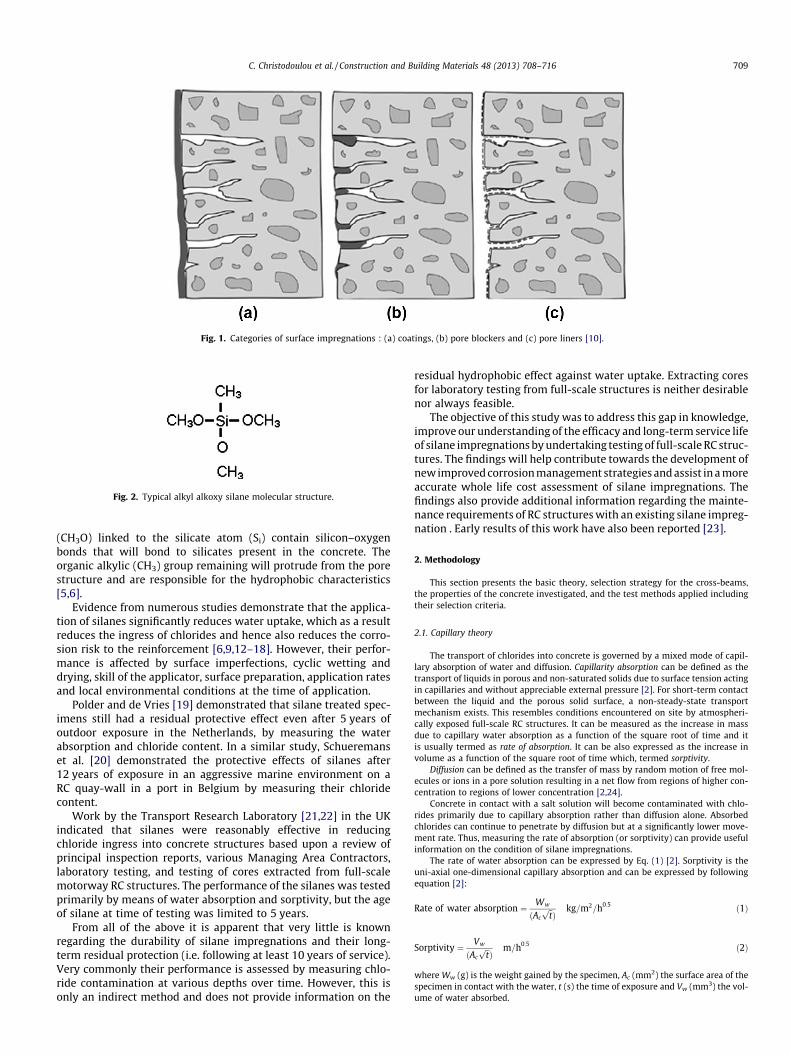
Fig. 1. Categories of surface impregnations : (a) coatings, (b) pore blockers and (c) pore liners [10].
Fig. 2. Typical alkyl alkoxy silane molecular structure.
C. Christodoulou et al. / Construction and Building Materials 48 (2013) 708–716 709
(CH3O) linked to the silicate atom (Si) contain silicon–oxygenbonds that will bond to silicates present in the concrete. Theorganic alkylic (CH3) group remaining will protrude from the porestructure and are responsible for the hydrophobic characteristics[5,6].
Evidence from numerous studies demonstrate that the applica-tion of silanes significantly reduces water uptake, which as a resultreduces the ingress of chlorides and hence also reduces the corro-sion risk to the reinforcement [6,9,12–18]. However, their perfor-mance is affected by surface imperfections, cyclic wetting anddrying, skill of the applicator, surface preparation, application ratesand local environmental conditions at the time of application.
Polder and de Vries [19] demonstrated that silane treated spec-imens still had a residual protective effect even after 5 years ofoutdoor exposure in the Netherlands, by measuring the waterabsorption and chloride content. In a similar study, Schueremanset al. [20] demonstrated the protective effects of silanes after12 years of exposure in an aggressive marine environment on aRC quay-wall in a port in Belgium by measuring their chloridecontent.
Work by the Transport Research Laboratory [21,22] in the UKindicated that silanes were reasonably effective in reducingchloride ingress into concrete structures based upon a review ofprincipal inspection reports, various Managing Area Contractors,laboratory testing, and testing of cores extracted from full-scalemotorway RC structures. The performance of the silanes was testedprimarily by means of water absorption and sorptivity, but the ageof silane at time of testing was limited to 5 years.
From all of the above it is apparent that very little is knownregarding the durability of silane impregnations and their long-term residual protection (i.e. following at least 10 years of service).Very commonly their performance is assessed by measuring chlo-ride contamination at various depths over time. However, this isonly an indirect method and does not provide information on the
residual hydrophobic effect against water uptake. Extracting coresfor laboratory testing from full-scale structures is neither desirablenor always feasible.
The objective of this study was to address this gap in knowledge,improve our understanding of the efficacy and long-term service lifeof silane impregnations by undertaking testing of full-scale RC struc-tures. The findings will help contribute towards the development ofnew improved corrosion management strategies and assist in a moreaccurate whole life cost assessment of silane impregnations. Thefindings also provide additional information regarding the mainte-nance requirements of RC structures with an existing silane impreg-nation . Early results of this work have also been reported [23].
2. Methodology
This section presents the basic theory, selection strategy for the cross-beams,the properties of the concrete investigated, and the test methods applied includingtheir selection criteria.
2.1. Capillary theory
The transport of chlorides into concrete is governed by a mixed mode of capil-lary absorption of water and diffusion. Capillarity absorption can be defined as thetransport of liquids in porous and non-saturated solids due to surface tension actingin capillaries and without appreciable external pressure [2]. For short-term contactbetween the liquid and the porous solid surface, a non-steady-state transportmechanism exists. This resembles conditions encountered on site by atmospheri-cally exposed full-scale RC structures. It can be measured as the increase in massdue to capillary water absorption as a function of the square root of time and itis usually termed as rate of absorption. It can be also expressed as the increase involume as a function of the square root of time which, termed sorptivity.
Diffusion can be defined as the transfer of mass by random motion of free mol-ecules or ions in a pore solution resulting in a net flow from regions of higher con-centration to regions of lower concentration [2,24].
Concrete in contact with a salt solution will become contaminated with chlo-rides primarily due to capillary absorption rather than diffusion alone. Absorbedchlorides can continue to penetrate by diffusion but at a significantly lower move-ment rate. Thus, measuring the rate of absorption (or sorptivity) can provide usefulinformation on the condition of silane impregnations.
The rate of water absorption can be expressed by Eq. (1) [2]. Sorptivity is theuni-axial one-dimensional capillary absorption and can be expressed by followingequation [2]:
Rate of water absorption ¼ Ww
ðAc
ffiffi
tpÞ
kg=m2=h0:5 ð1Þ
Sorptivity ¼ Vw
ðAc
ffiffi
tpÞ
m=h0:5 ð2Þ
where Ww (g) is the weight gained by the specimen, Ac (mm2) the surface area of thespecimen in contact with the water, t (s) the time of exposure and Vw (mm3) the vol-ume of water absorbed.
710 C. Christodoulou et al. / Construction and Building Materials 48 (2013) 708–716
Measurement of water sorptivity can also be related to the rate of chlorideabsorption [10,25].
Table 1 provides a summary of the European Standard BS EN 13057 [26] formeasurement of the capillary water absorption of hardened concrete.
2.2. Cross-beams
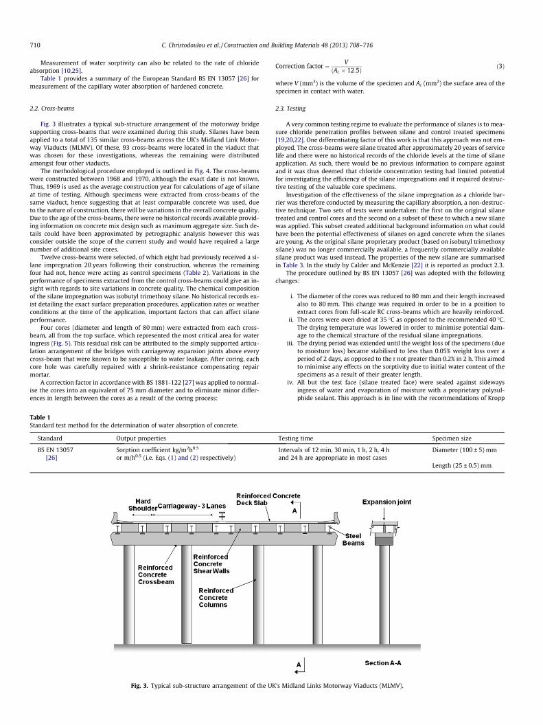
Fig. 3 illustrates a typical sub-structure arrangement of the motorway bridgesupporting cross-beams that were examined during this study. Silanes have beenapplied to a total of 135 similar cross-beams across the UK’s Midland Link Motor-way Viaducts (MLMV). Of these, 93 cross-beams were located in the viaduct thatwas chosen for these investigations, whereas the remaining were distributedamongst four other viaducts.
The methodological procedure employed is outlined in Fig. 4. The cross-beamswere constructed between 1968 and 1970, although the exact date is not known.Thus, 1969 is used as the average construction year for calculations of age of silaneat time of testing. Although specimens were extracted from cross-beams of thesame viaduct, hence suggesting that at least comparable concrete was used, dueto the nature of construction, there will be variations in the overall concrete quality.Due to the age of the cross-beams, there were no historical records available provid-ing information on concrete mix design such as maximum aggregate size. Such de-tails could have been approximated by petrographic analysis however this wasconsider outside the scope of the current study and would have required a largenumber of additional site cores.
Twelve cross-beams were selected, of which eight had previously received a si-lane impregnation 20 years following their construction, whereas the remainingfour had not, hence were acting as control specimens (Table 2). Variations in theperformance of specimens extracted from the control cross-beams could give an in-sight with regards to site variations in concrete quality. The chemical compositionof the silane impregnation was isobutyl trimethoxy silane. No historical records ex-ist detailing the exact surface preparation procedures, application rates or weatherconditions at the time of the application, important factors that can affect silaneperformance.
Four cores (diameter and length of 80 mm) were extracted from each cross-beam, all from the top surface, which represented the most critical area for wateringress (Fig. 5). This residual risk can be attributed to the simply supported articu-lation arrangement of the bridges with carriageway expansion joints above everycross-beam that were known to be susceptible to water leakage. After coring, eachcore hole was carefully repaired with a shrink-resistance compensating repairmortar.
A correction factor in accordance with BS 1881-122 [27] was applied to normal-ise the cores into an equivalent of 75 mm diameter and to eliminate minor differ-ences in length between the cores as a result of the coring process:
Table 1Standard test method for the determination of water absorption of concrete.
Standard Output properties
BS EN 13057[26]
Sorption coefficient kg/m2h0.5
or m/h0.5 (i.e. Eqs. (1) and (2) respectively)
Fig. 3. Typical sub-structure arrangement of the UK
Correction factor ¼ VðAc � 12:5Þ ð3Þ
where V (mm3) is the volume of the specimen and Ac (mm2) the surface area of thespecimen in contact with water.
2.3. Testing
A very common testing regime to evaluate the performance of silanes is to mea-sure chloride penetration profiles between silane and control treated specimens[19,20,22]. One differentiating factor of this work is that this approach was not em-ployed. The cross-beams were silane treated after approximately 20 years of servicelife and there were no historical records of the chloride levels at the time of silaneapplication. As such, there would be no previous information to compare againstand it was thus deemed that chloride concentration testing had limited potentialfor investigating the efficiency of the silane impregnations and it required destruc-tive testing of the valuable core specimens.
Investigation of the effectiveness of the silane impregnation as a chloride bar-rier was therefore conducted by measuring the capillary absorption, a non-destruc-tive technique. Two sets of tests were undertaken: the first on the original silanetreated and control cores and the second on a subset of these to which a new silanewas applied. This subset created additional background information on what couldhave been the potential effectiveness of silanes on aged concrete when the silanesare young. As the original silane proprietary product (based on isobutyl trimethoxysilane) was no longer commercially available, a frequently commercially availablesilane product was used instead. The properties of the new silane are summarisedin Table 3. In the study by Calder and McKenzie [22] it is reported as product 2.3.
The procedure outlined by BS EN 13057 [26] was adopted with the followingchanges:
i. The diameter of the cores was reduced to 80 mm and their length increasedalso to 80 mm. This change was required in order to be in a position toextract cores from full-scale RC cross-beams which are heavily reinforced.
ii. The cores were oven dried at 35 �C as opposed to the recommended 40 �C.The drying temperature was lowered in order to minimise potential dam-age to the chemical structure of the residual silane impregnations.
iii. The drying period was extended until the weight loss of the specimens (dueto moisture loss) became stabilised to less than 0.05% weight loss over aperiod of 2 days, as opposed to the r not greater than 0.2% in 2 h. This aimedto minimise any effects on the sorptivity due to initial water content of thespecimens as a result of their greater length.
iv. All but the test face (silane treated face) were sealed against sidewaysingress of water and evaporation of moisture with a proprietary polysul-phide sealant. This approach is in line with the recommendations of Kropp
Testing time Specimen size
Intervals of 12 min, 30 min, 1 h, 2 h, 4 hand 24 h are appropriate in most cases
Diameter (100 ± 5) mm
Length (25 ± 0.5) mm
’s Midland Links Motorway Viaducts (MLMV).
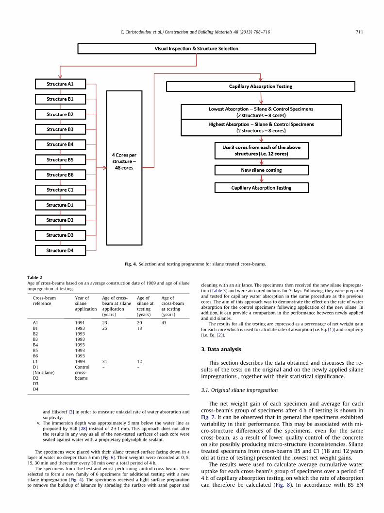
Fig. 4. Selection and testing programme for silane treated cross-beams.
Table 2Age of cross-beams based on an average construction date of 1969 and age of silaneimpregnation at testing.
Cross-beamreference
Year ofsilaneapplication
Age of cross-beam at silaneapplication(years)
Age ofsilane attesting(years)
Age ofcross-beamat testing(years)
A1 1991 23 20 43B1 1993 25 18B2 1993B3 1993B4 1993B5 1993B6 1993C1 1999 31 12D1 Control
cross-beams
– –(No silane)D2D3D4
C. Christodoulou et al. / Construction and Building Materials 48 (2013) 708–716 711
and Hilsdorf [2] in order to measure uniaxial rate of water absorption andsorptivity.
v. The immersion depth was approximately 5 mm below the water line asproposed by Hall [28] instead of 2 ± 1 mm. This approach does not alterthe results in any way as all of the non-tested surfaces of each core weresealed against water with a proprietary polysulphide sealant.
The specimens were placed with their silane treated surface facing down in alayer of water no deeper than 5 mm (Fig. 6). Their weights were recorded at 0, 5,15, 30 min and thereafter every 30 min over a total period of 4 h.
The specimens from the best and worst performing control cross-beams wereselected to form a new family of 6 specimens for additional testing with a newsilane impregnation (Fig. 4). The specimens received a light surface preparationto remove the buildup of laitance by abrading the surface with sand paper and
cleaning with an air lance. The specimens then received the new silane impregna-tion (Table 3) and were air cured indoors for 7 days. Following, they were preparedand tested for capillary water absorption in the same procedure as the previouscores. The aim of this approach was to demonstrate the effect on the rate of waterabsorption for the control specimens following application of the new silane. Inaddition, it can provide a comparison in the performance between newly appliedand old silanes.
The results for all the testing are expressed as a percentage of net weight gainfor each core which is used to calculate rate of absorption (i.e. Eq. (1)) and sorptivity(i.e. Eq. (2)).
3. Data analysis
This section describes the data obtained and discusses the re-sults of the tests on the original and on the newly applied silaneimpregnations , together with their statistical significance.
3.1. Original silane impregnation
The net weight gain of each specimen and average for eachcross-beam’s group of specimens after 4 h of testing is shown inFig. 7. It can be observed that in general the specimens exhibitedvariability in their performance. This may be associated with mi-cro-structure differences of the specimens, even for the samecross-beam, as a result of lower quality control of the concreteon site possibly producing micro-structure inconsistencies. Silanetreated specimens from cross-beams B5 and C1 (18 and 12 yearsold at time of testing) presented the lowest net weight gains.
The results were used to calculate average cumulative wateruptake for each cross-beam’s group of specimens over a period of4 h of capillary absorption testing, on which the rate of absorptioncan therefore be calculated (Fig. 8). In accordance with BS EN
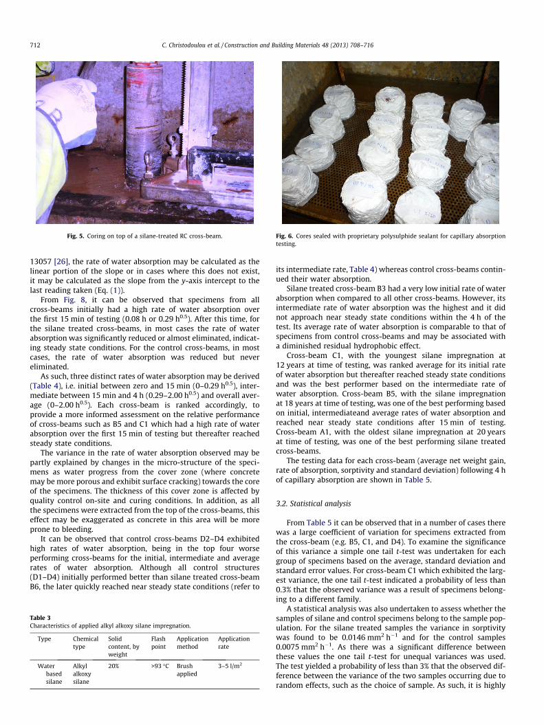
Fig. 5. Coring on top of a silane-treated RC cross-beam. Fig. 6. Cores sealed with proprietary polysulphide sealant for capillary absorptiontesting.
712 C. Christodoulou et al. / Construction and Building Materials 48 (2013) 708–716
13057 [26], the rate of water absorption may be calculated as thelinear portion of the slope or in cases where this does not exist,it may be calculated as the slope from the y-axis intercept to thelast reading taken (Eq. (1)).
From Fig. 8, it can be observed that specimens from allcross-beams initially had a high rate of water absorption overthe first 15 min of testing (0.08 h or 0.29 h0.5). After this time, forthe silane treated cross-beams, in most cases the rate of waterabsorption was significantly reduced or almost eliminated, indicat-ing steady state conditions. For the control cross-beams, in mostcases, the rate of water absorption was reduced but nevereliminated.
As such, three distinct rates of water absorption may be derived(Table 4), i.e. initial between zero and 15 min (0–0.29 h0.5), inter-mediate between 15 min and 4 h (0.29–2.00 h0.5) and overall aver-age (0–2.00 h0.5). Each cross-beam is ranked accordingly, toprovide a more informed assessment on the relative performanceof cross-beams such as B5 and C1 which had a high rate of waterabsorption over the first 15 min of testing but thereafter reachedsteady state conditions.
The variance in the rate of water absorption observed may bepartly explained by changes in the micro-structure of the speci-mens as water progress from the cover zone (where concretemay be more porous and exhibit surface cracking) towards the coreof the specimens. The thickness of this cover zone is affected byquality control on-site and curing conditions. In addition, as allthe specimens were extracted from the top of the cross-beams, thiseffect may be exaggerated as concrete in this area will be moreprone to bleeding.
It can be observed that control cross-beams D2–D4 exhibitedhigh rates of water absorption, being in the top four worseperforming cross-beams for the initial, intermediate and averagerates of water absorption. Although all control structures(D1–D4) initially performed better than silane treated cross-beamB6, the later quickly reached near steady state conditions (refer to
Table 3Characteristics of applied alkyl alkoxy silane impregnation.
Type Chemicaltype
Solidcontent, byweight
Flashpoint
Applicationmethod
Applicationrate
Waterbasedsilane
Alkylalkoxysilane
20% >93 �C Brushapplied
3–5 l/m2
its intermediate rate, Table 4) whereas control cross-beams contin-ued their water absorption.
Silane treated cross-beam B3 had a very low initial rate of waterabsorption when compared to all other cross-beams. However, itsintermediate rate of water absorption was the highest and it didnot approach near steady state conditions within the 4 h of thetest. Its average rate of water absorption is comparable to that ofspecimens from control cross-beams and may be associated witha diminished residual hydrophobic effect.
Cross-beam C1, with the youngest silane impregnation at12 years at time of testing, was ranked average for its initial rateof water absorption but thereafter reached steady state conditionsand was the best performer based on the intermediate rate ofwater absorption. Cross-beam B5, with the silane impregnationat 18 years at time of testing, was one of the best performing basedon initial, intermediateand average rates of water absorption andreached near steady state conditions after 15 min of testing.Cross-beam A1, with the oldest silane impregnation at 20 yearsat time of testing, was one of the best performing silane treatedcross-beams.
The testing data for each cross-beam (average net weight gain,rate of absorption, sorptivity and standard deviation) following 4 hof capillary absorption are shown in Table 5.
3.2. Statistical analysis
From Table 5 it can be observed that in a number of cases therewas a large coefficient of variation for specimens extracted fromthe cross-beam (e.g. B5, C1, and D4). To examine the significanceof this variance a simple one tail t-test was undertaken for eachgroup of specimens based on the average, standard deviation andstandard error values. For cross-beam C1 which exhibited the larg-est variance, the one tail t-test indicated a probability of less than0.3% that the observed variance was a result of specimens belong-ing to a different family.
A statistical analysis was also undertaken to assess whether thesamples of silane and control specimens belong to the sample pop-ulation. For the silane treated samples the variance in sorptivitywas found to be 0.0146 mm2 h�1 and for the control samples0.0075 mm2 h�1. As there was a significant difference betweenthese values the one tail t-test for unequal variances was used.The test yielded a probability of less than 3% that the observed dif-ference between the variance of the two samples occurring due torandom effects, such as the choice of sample. As such, it is highly
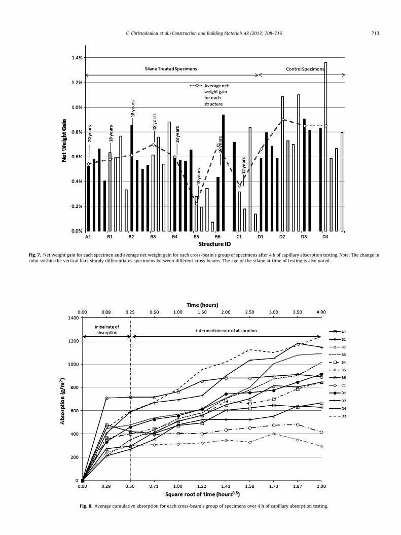
Fig. 7. Net weight gain for each specimen and average net weight gain for each cross-beam’s group of specimens after 4 h of capillary absorption testing. Note: The change incolor within the vertical bars simply differentiates specimens between different cross-beams. The age of the silane at time of testing is also noted.
Fig. 8. Average cumulative absorption for each cross-beam’s group of specimens over 4 h of capillary absorption testing.
C. Christodoulou et al. / Construction and Building Materials 48 (2013) 708–716 713
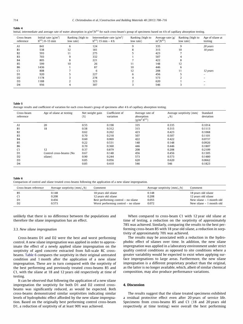
Table 4Initial, intermediate and average rate of water absorption in g/m2/h0.5 for each cross-beam’s group of specimens based on 4 h of capillary absorption testing.
Cross-beamreference
Initial rate (g/m2/h0.5) 0–15 min
Ranking (high tolow rate)
Intermediate rate (g/m2/h0.5) 15 min – 4 h
Ranking (high tolow rate)
Average rate (g/m2/h0.5)
Ranking (high tolow rate)
Age of silane attesting
A1 841 6 124 9 335 9 20 yearsB1 538 12 181 8 315 10 18 yearsB2 593 11 275 5 423 7B3 703 9 332 1 507 4B4 805 8 221 7 422 8B5 599 10 26 11 148 12B6 1436 1 87 10 446 6C1 808 7 6 12 208 11 12 yearsD1 920 5 227 6 456 5 –D2 1178 3 278 4 573 2 –D3 1188 2 323 2 620 1 –D4 956 4 307 3 546 3 –
Table 5Average results and coefficient of variation for each cross-beam’s group of specimens after 4 h of capillary absorption testing.
Cross-beamreference
Age of silane at testing Net weight gain(%)
Coefficient ofvariation
Average rate ofabsorption(g/m2 h0.5)
Average sorptivity (mm/ph)
Standarddeviation
A1 20 0.55 0.198 335 0.335 0.1014B1 18 0.58 0.312 315 0.315 0.1113B2 0.62 0.262 423 0.423 0.1068B3 0.70 0.218 507 0.507 0.1101B4 0.60 0.069 422 0.422 0.0737B5 0.22 0.531 148 0.148 0.0926B6 0.70 0.360 446 0.446 0.1807C1 12 0.37 0.879 208 0.208 0.2109D1 Control cross-beams (No
silane)0.67 0.148 456 0.456 0.1305
D2 0.90 0.244 573 0.573 0.1480D3 0.85 0.056 620 0.620 0.0662D4 0.85 0.410 546 546 0.1823
Table 6Comparison of control and silane treated cross-beams following the application of a new silane impregnation.
Cross-beam reference Average sorptivity (mm/p
h) Comment Average sorptivity (mm/p
h) Comment
B5 0.148 18 years old silane 0.148 18 years old silaneC1 0.208 12 years old silane 0.208 12 years old silaneD1 0.456 Best performing control – no silane 0.055 New silane – 1 month oldD2 0.573 Worst performing control – no silane 0.072 New silane – 1 month old
714 C. Christodoulou et al. / Construction and Building Materials 48 (2013) 708–716
unlikely that there is no difference between the populations andtherefore the silane impregnation has an effect.
3.3. New silane impregnation
Cross-beams D1 and D2 were the best and worst performingcontrol. A new silane impregnation was applied in order to approx-imate the effect of a newly applied silane impregnation on thesorptivity of aged concrete extracted from full-scale RC cross-beams. Table 6 compares the sorptivity in their original untreatedcondition and 1 month after the application of a new silaneimpregnation. These are in turn compared with the sorptivity ofthe best performing and previously treated cross-beams B5 andC1, with the silane at 18 and 12 years old respectively at time oftesting.
It can be observed that following the application of a new silaneimpregnation the sorptivity for both D1 and D2 control cross-beams was significantly reduced, as would be expected. Bothcross-beams demonstrated similar sorptivities indicating similarlevels of hydrophobic effect afforded by the new silane impregna-tion. Based on the originally best performing control cross-beamD1, a reduction of sorptivity of at least 90% was achieved.
When compared to cross-beam C1 with 12 year old silane attime of testing, a reduction on the sorptivity of approximately78% was achieved. Similarly, comparing the results to the best per-forming cross-beam B5 with 18 year old silane, a reduction in sorp-tivity of approximately 70% was achieved.
The results may be associated with a reduction in the hydro-phobic effect of silanes over time. In addition, the new silaneimpregnation was applied in a laboratory environment under strictquality control conditions as opposed to site conditions where agreater variability would be expected to exist when applying sur-face impregnations to large areas. Furthermore, the new silaneimpregnation is a different proprietary product than the original,as the latter is no longer available, which, albeit of similar chemicalcomposition, may also produce performance variations.
4. Discussion
The results suggest that the silane treated specimens exhibiteda residual protective effect even after 20 years of service life.Specimens from cross-beams B5 and C1 (18 and 20 years oldrespectively at time testing) were overall the best performing
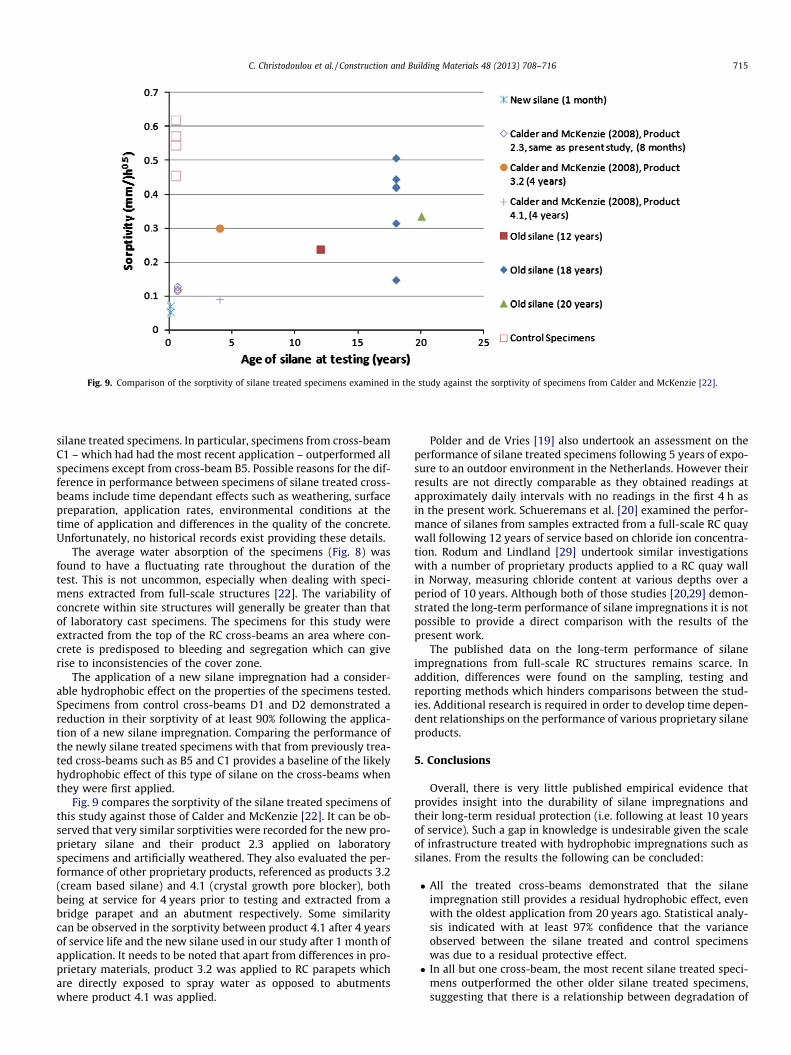
Fig. 9. Comparison of the sorptivity of silane treated specimens examined in the study against the sorptivity of specimens from Calder and McKenzie [22].
C. Christodoulou et al. / Construction and Building Materials 48 (2013) 708–716 715
silane treated specimens. In particular, specimens from cross-beamC1 – which had had the most recent application – outperformed allspecimens except from cross-beam B5. Possible reasons for the dif-ference in performance between specimens of silane treated cross-beams include time dependant effects such as weathering, surfacepreparation, application rates, environmental conditions at thetime of application and differences in the quality of the concrete.Unfortunately, no historical records exist providing these details.
The average water absorption of the specimens (Fig. 8) wasfound to have a fluctuating rate throughout the duration of thetest. This is not uncommon, especially when dealing with speci-mens extracted from full-scale structures [22]. The variability ofconcrete within site structures will generally be greater than thatof laboratory cast specimens. The specimens for this study wereextracted from the top of the RC cross-beams an area where con-crete is predisposed to bleeding and segregation which can giverise to inconsistencies of the cover zone.
The application of a new silane impregnation had a consider-able hydrophobic effect on the properties of the specimens tested.Specimens from control cross-beams D1 and D2 demonstrated areduction in their sorptivity of at least 90% following the applica-tion of a new silane impregnation. Comparing the performance ofthe newly silane treated specimens with that from previously trea-ted cross-beams such as B5 and C1 provides a baseline of the likelyhydrophobic effect of this type of silane on the cross-beams whenthey were first applied.
Fig. 9 compares the sorptivity of the silane treated specimens ofthis study against those of Calder and McKenzie [22]. It can be ob-served that very similar sorptivities were recorded for the new pro-prietary silane and their product 2.3 applied on laboratoryspecimens and artificially weathered. They also evaluated the per-formance of other proprietary products, referenced as products 3.2(cream based silane) and 4.1 (crystal growth pore blocker), bothbeing at service for 4 years prior to testing and extracted from abridge parapet and an abutment respectively. Some similaritycan be observed in the sorptivity between product 4.1 after 4 yearsof service life and the new silane used in our study after 1 month ofapplication. It needs to be noted that apart from differences in pro-prietary materials, product 3.2 was applied to RC parapets whichare directly exposed to spray water as opposed to abutmentswhere product 4.1 was applied.
Polder and de Vries [19] also undertook an assessment on theperformance of silane treated specimens following 5 years of expo-sure to an outdoor environment in the Netherlands. However theirresults are not directly comparable as they obtained readings atapproximately daily intervals with no readings in the first 4 h asin the present work. Schueremans et al. [20] examined the perfor-mance of silanes from samples extracted from a full-scale RC quaywall following 12 years of service based on chloride ion concentra-tion. Rodum and Lindland [29] undertook similar investigationswith a number of proprietary products applied to a RC quay wallin Norway, measuring chloride content at various depths over aperiod of 10 years. Although both of those studies [20,29] demon-strated the long-term performance of silane impregnations it is notpossible to provide a direct comparison with the results of thepresent work.
The published data on the long-term performance of silaneimpregnations from full-scale RC structures remains scarce. Inaddition, differences were found on the sampling, testing andreporting methods which hinders comparisons between the stud-ies. Additional research is required in order to develop time depen-dent relationships on the performance of various proprietary silaneproducts.
5. Conclusions
Overall, there is very little published empirical evidence thatprovides insight into the durability of silane impregnations andtheir long-term residual protection (i.e. following at least 10 yearsof service). Such a gap in knowledge is undesirable given the scaleof infrastructure treated with hydrophobic impregnations such assilanes. From the results the following can be concluded:
� All the treated cross-beams demonstrated that the silaneimpregnation still provides a residual hydrophobic effect, evenwith the oldest application from 20 years ago. Statistical analy-sis indicated with at least 97% confidence that the varianceobserved between the silane treated and control specimenswas due to a residual protective effect.� In all but one cross-beam, the most recent silane treated speci-
mens outperformed the other older silane treated specimens,suggesting that there is a relationship between degradation of

716 C. Christodoulou et al. / Construction and Building Materials 48 (2013) 708–716
the silane impregnation and duration of environmentalexposure.� Silane impregnations should be considered when determining
the corrosion management strategy of a RC structure. Impreg-nations as old as 20 years can still be present and offer a resid-ual protective effect. Their presence and effectiveness can beevaluated by extracting cores and testing them in the laboratoryby capillary absorption testing.
Acknowledgements
The authors would like to thank AECOM, the EPSRC (throughthe Centre for Innovative and Collaborative Engineering at Lough-borough University) and the Highways Agency for their commer-cial and financial support. This work was funded by theEngineering and Physical Sciences Research Council (Grant No.EP/G037272/1).
References
[1] Concrete Society. Technical Report 31. Permeability testing of site concrete.Surrey (UK), 2008.
[2] Kropp J, Hilsdorf HK. RILEM Report 12. Performance criteria for concretedurability. Oxford (UK): Taylor and Francis; 1995.
[3] Ungricht H. Wasserhaushalt und Chlorideintrag in Beton – Einfulls derExposition und der Betonzusammensetzung. In: Ph. D. thesis. Universities ofZurich and Basel; 2004. [in German].
[4] Basheer PAM, Basheer L, Cleland DJ, Long AE. Surface treatments for concrete:assessment methods and reported performance. Constr Build Mater1997;11:413–29.
[5] Ibrahim M, Al-Gahtani S, Maslehuddin M, Almusallam AA. Effectiveness ofconcrete surface treatment materials in reducing chloride-inducedreinforcement corrosion. Constr Build Mater 1997;11:443–51.
[6] Vries J, Polder RB. Hydrophobic treatment of concrete. Constr Build Mater1997;11:259–65.
[7] Almusallam AA, Khan FM, Dulajan SU, Al-Amoudi OSB. Effectiveness of surfacecoatings in improving concrete durability. Cem Concr Compos2003;25:381–473.
[8] Yang CC, Wang LC, Weng TL. Using charge passed and total chloride content toassess the effect of penetrating silane sealer on the transport properties ofconcrete. Mater Chem Phys 2004;85:238–44.
[9] Medeiros MHF, Helene P. Efficacy of surface hydrophobic agents in reducingwater and chloride ion penetration in concrete. Mater Struct 2008;41:59–71.
[10] Medeiros MHF, Helene P. Surface treatment of reinforced concrete in marineenvironment: Influence on chloride diffusion coefficient and capillary waterabsorption. Constr Build Mater 2009;23:1476–84.
[11] Concrete Society. Technical Report 50. Guide to surface treatments forprotection and enhancement of concrete. Surrey (UK), 1997.
[12] Pfeifer DW, Scali J. Concrete sealers for protection of bridge structures,department of transportation. NCHRP 244. Washington (DC); 1981.
[13] Thompson JL, Silsbee MR, Gill PM, Scheetz BE. Characterization of silicatesealers on concrete. Cem Concr Res 1997;27:1561–7.
[14] Delucchi M, Barbucci A, Cerisola G. Study of the physico-chemical properties oforganic coatings for concrete degradation control. Const Build Mater1997;11:365–71.
[15] Seneviratne AMG, Sergi G, Page CL. Performance characteristics of surfacecoatings applied to concrete for control of reinforcement corrosion. ConstrBuild Mater 2000;14:55–9.
[16] Al-Zahrani MM, Al-Dulaijan SU, Ibrahim M, Saricimen H, Sharif FM. Effect ofwaterproofing coatings on steel reinforcement corrosion and physicalproperties of concrete. Cem Concr Compos 2002;24:127–37.
[17] Moon HY, Shin DG, Choi DS. Evaluation of the durability of mortar andconcrete applied with inorganic coating material and surface treatmentsystem. Constr Build Mater 2007;21:362–9.
[18] Woo RSC, Zhu H, Chow MMK, Leung CKY, Jang-Kyo K. Barrier performance ofsilane-clay nanocomposite coatings on concrete structure. Compos Sci Technol2008;68:2828–36.
[19] Polder RB, de Vries H. Prevention of reinforcement corrosion by hydrophobictreatment of concrete. Heron 2001;46:227–38.
[20] Schueremans L, Gemert DV, Giessler S. Chloride penetration in RC-structuresin marine environment-Long term assessment of a preventative hydrophobictreatment. Constr Build Mater 2007;21:1238–49.
[21] Calder A, Anderson N, McKenzie M. Survey of impregnated structures.Published Project Report 136. Transportation Research Laboratory; 2006.
[22] Calder A, McKenzie M. Performance of impregnants. Published Project Report362. Transportation Research Laboratory; 2008.
[23] Christodoulou C, Goodier C, Austin S, Glass G, Webb J. Assessing the long-termdurability of silanes on reinforced concrete structures. In: 1st Internationalcongress on durability of concrete. Trondheim (Norway), 2012, ISBN 978-82-8208-031-6.
[24] Glass GK, Buenfeld NR. Chloride-induced corrosion of steel in concrete. ProgStruct Eng Mater 2000;2:448–58.
[25] Austin SA, Al-Kindy AA. Air permeability versus sorptivity: effects of fieldcuring on cover concrete after one year of field exposure. Mag Concr Res2000;52:17–24.
[26] British Standards Institution. BS EN 13057:2002. Products and systems for theprotection and repair of concrete structures – test methods – determination ofresistance of capillary absorption. London: BSI; 2002.
[27] British Standards Institution. BS 1881-122:1983. Method for determination ofwater absorption. BSI, London, 1983.
[28] Hall C. Water sorptivity of mortars and concrete, a review. Mag Concr Res1989;41:51–61.
[29] Rodum E, Lindland J. Effect of different surface treatment products after 10years of field exposure. In: Proceedings of the 1st international congress ondurability of concrete. Trondheim (Norway). June 17–21; 2012, ISBN 978-82-8208-031-6.