Embed Size (px)
Citation preview
Loughborough UniversityInstitutional Repository
Long-term performance ofsurface impregnation of
reinforced concretestructures with silane
This item was submitted to Loughborough University's Institutional Repositoryby the/an author.
Citation: CHRISTODOULOU, C. ... et al., 2013. Long-term performance ofsurface impregnation of reinforced concrete structures with silane. Constructionand Building Materials, 48, pp.708-716.
Additional Information:
• This is the author's version of a work that was accepted for publication inthe journal, Construction and Building Materials. Changes resulting fromthe publishing process, such as peer review, editing, corrections, structuralformatting, and other quality control mechanisms may not be reflected inthis document. Changes may have been made to this work since it wassubmitted for publication. A definitive version was subsequently pub-lished at: http://dx.doi.org/10.1016/j.conbuildmat.2013.07.038
Metadata Record: https://dspace.lboro.ac.uk/2134/13023
Version: Accepted for publication
Publisher: c© Elsevier
Please cite the published version.
This item was submitted to Loughborough’s Institutional Repository (https://dspace.lboro.ac.uk/) by the author and is made available under the
following Creative Commons Licence conditions.
For the full text of this licence, please go to: http://creativecommons.org/licenses/by-nc-nd/2.5/
1
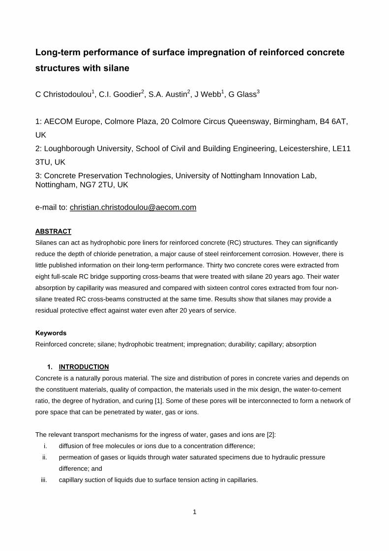
Long-term performance of surface impregnation of reinforced concrete
structures with silane
C Christodoulou1, C.I. Goodier2, S.A. Austin2, J Webb1, G Glass3
1: AECOM Europe, Colmore Plaza, 20 Colmore Circus Queensway, Birmingham, B4 6AT,
UK
2: Loughborough University, School of Civil and Building Engineering, Leicestershire, LE11
3TU, UK
3: Concrete Preservation Technologies, University of Nottingham Innovation Lab, Nottingham, NG7 2TU, UK
e-mail to: [email protected]
ABSTRACT
Silanes can act as hydrophobic pore liners for reinforced concrete (RC) structures. They can significantly
reduce the depth of chloride penetration, a major cause of steel reinforcement corrosion. However, there is
little published information on their long-term performance. Thirty two concrete cores were extracted from
eight full-scale RC bridge supporting cross-beams that were treated with silane 20 years ago. Their water
absorption by capillarity was measured and compared with sixteen control cores extracted from four non-
silane treated RC cross-beams constructed at the same time. Results show that silanes may provide a
residual protective effect against water even after 20 years of service.
Keywords
Reinforced concrete; silane; hydrophobic treatment; impregnation; durability; capillary; absorption
1. INTRODUCTION
Concrete is a naturally porous material. The size and distribution of pores in concrete varies and depends on
the constituent materials, quality of compaction, the materials used in the mix design, the water-to-cement
ratio, the degree of hydration, and curing [1]. Some of these pores will be interconnected to form a network of
pore space that can be penetrated by water, gas or ions.
The relevant transport mechanisms for the ingress of water, gases and ions are [2]:
i. diffusion of free molecules or ions due to a concentration difference;
ii. permeation of gases or liquids through water saturated specimens due to hydraulic pressure
difference; and
iii. capillary suction of liquids due to surface tension acting in capillaries.
2
Whilst, these mechanisms act together under natural environmental exposure conditions for atmospherically
exposed concrete, capillary suction tends to be the dominant mechanism [1-3]. Ions such as chlorides are
transported into the concrete pore system by being dissolved into water, which subsequently cause corrosion
of the steel reinforcement and ultimately spalling of the surrounding concrete cover.
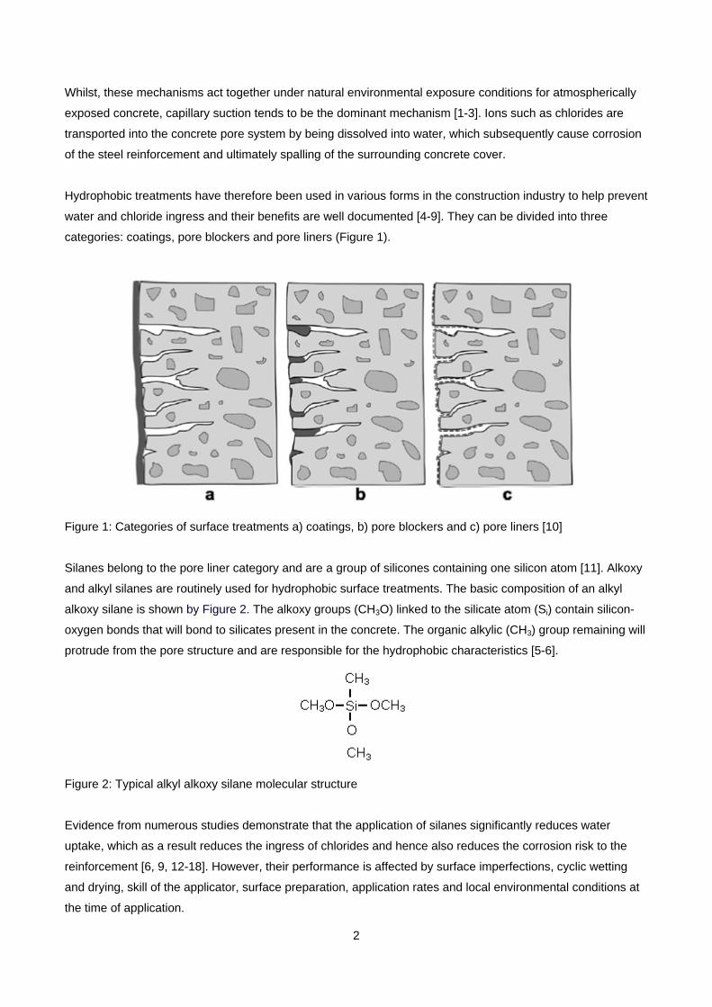
Hydrophobic treatments have therefore been used in various forms in the construction industry to help prevent
water and chloride ingress and their benefits are well documented [4-9]. They can be divided into three
categories: coatings, pore blockers and pore liners (Figure 1).
Figure 1: Categories of surface treatments a) coatings, b) pore blockers and c) pore liners [10]
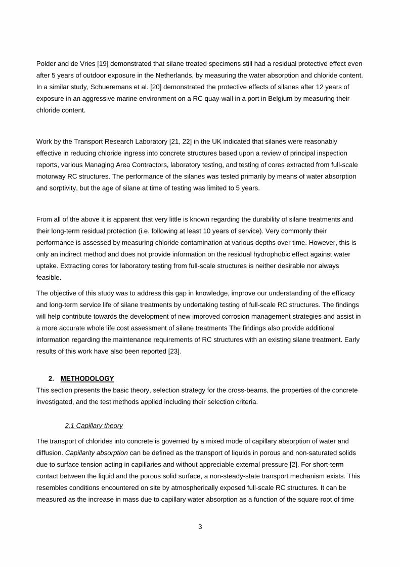
Silanes belong to the pore liner category and are a group of silicones containing one silicon atom [11]. Alkoxy
and alkyl silanes are routinely used for hydrophobic surface treatments. The basic composition of an alkyl
alkoxy silane is shown by Figure 2. The alkoxy groups (CH3O) linked to the silicate atom (Si) contain silicon-
oxygen bonds that will bond to silicates present in the concrete. The organic alkylic (CH3) group remaining will
protrude from the pore structure and are responsible for the hydrophobic characteristics [5-6].
Figure 2: Typical alkyl alkoxy silane molecular structure
Evidence from numerous studies demonstrate that the application of silanes significantly reduces water
uptake, which as a result reduces the ingress of chlorides and hence also reduces the corrosion risk to the
reinforcement [6, 9, 12-18]. However, their performance is affected by surface imperfections, cyclic wetting
and drying, skill of the applicator, surface preparation, application rates and local environmental conditions at
the time of application.
3
Polder and de Vries [19] demonstrated that silane treated specimens still had a residual protective effect even
after 5 years of outdoor exposure in the Netherlands, by measuring the water absorption and chloride content.
In a similar study, Schueremans et al. [20] demonstrated the protective effects of silanes after 12 years of
exposure in an aggressive marine environment on a RC quay-wall in a port in Belgium by measuring their
chloride content.
Work by the Transport Research Laboratory [21, 22] in the UK indicated that silanes were reasonably
effective in reducing chloride ingress into concrete structures based upon a review of principal inspection
reports, various Managing Area Contractors, laboratory testing, and testing of cores extracted from full-scale
motorway RC structures. The performance of the silanes was tested primarily by means of water absorption
and sorptivity, but the age of silane at time of testing was limited to 5 years.
From all of the above it is apparent that very little is known regarding the durability of silane treatments and
their long-term residual protection (i.e. following at least 10 years of service). Very commonly their
performance is assessed by measuring chloride contamination at various depths over time. However, this is
only an indirect method and does not provide information on the residual hydrophobic effect against water
uptake. Extracting cores for laboratory testing from full-scale structures is neither desirable nor always
feasible.
The objective of this study was to address this gap in knowledge, improve our understanding of the efficacy
and long-term service life of silane treatments by undertaking testing of full-scale RC structures. The findings
will help contribute towards the development of new improved corrosion management strategies and assist in
a more accurate whole life cost assessment of silane treatments The findings also provide additional
information regarding the maintenance requirements of RC structures with an existing silane treatment. Early
results of this work have also been reported [23].
2. METHODOLOGY
This section presents the basic theory, selection strategy for the cross-beams, the properties of the concrete
investigated, and the test methods applied including their selection criteria.
2.1 Capillary theory
The transport of chlorides into concrete is governed by a mixed mode of capillary absorption of water and
diffusion. Capillarity absorption can be defined as the transport of liquids in porous and non-saturated solids
due to surface tension acting in capillaries and without appreciable external pressure [2]. For short-term
contact between the liquid and the porous solid surface, a non-steady-state transport mechanism exists. This
resembles conditions encountered on site by atmospherically exposed full-scale RC structures. It can be
measured as the increase in mass due to capillary water absorption as a function of the square root of time

4
and it is usually termed as rate of absorption. It can be also expressed as the increase in volume as a function
of the square root of time which, termed sorptivity.
Diffusion can be defined as the transfer of mass by random motion of free molecules or ions in a pore solution
resulting in a net flow from regions of higher concentration to regions of lower concentration [2, 24].
Concrete in contact with a salt solution will become contaminated with chlorides primarily due to capillary
absorption rather than diffusion alone. Absorbed chlorides can continue to penetrate by diffusion but at a
significantly lower movement rate. Thus, measuring the rate of absorption (or sorptivity) can provide useful
information on the condition of silane treatments.
The rate of water absorption can be expressed by equation (1) [2]. Sorptivity is the uni-axial one-dimensional
capillary absorption and can be expressed by equation (2) [2].
5.02 //absorption water of Rate hmkg
tA
W
c
w Equ. (1)
5.0/Sorptivity hm
tA
V
c
w Equ. (2)
where Ww (grams) is the weight gained by the specimen, Ac (mm2) the surface area of the specimen in
contact with the water, t (seconds) the time of exposure and Vw (mm3) the volume of water absorbed.
Measurement of water sorptivity can also be related to the rate of chloride absorption [10, 25].
Table 1 provides a summary of the European Standard BS EN 13057 [26] for measurement of the capillary
water absorption of hardened concrete.
Standard Output Properties Testing Time Specimen Size
BS EN 13057
[26]
Sorption coefficient
kg/m2h0.5 or m/h0.5
(i.e. equations 1 and
2 respectively)
Intervals of 12 min, 30 min, 1
h, 2 h, 4 h and 24 h are
appropriate in most cases.
Diameter (100 + 5) mm
Length (25 + 0.5) mm
Table 1: Standard test method for the determination of water absorption of concrete
5
2.2. Cross-Beams
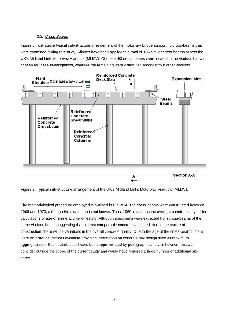
Figure 3 illustrates a typical sub-structure arrangement of the motorway bridge supporting cross-beams that
were examined during this study. Silanes have been applied to a total of 135 similar cross-beams across the
UK’s Midland Link Motorway Viaducts (MLMV). Of these, 93 cross-beams were located in the viaduct that was
chosen for these investigations, whereas the remaining were distributed amongst four other viaducts.
Figure 3: Typical sub-structure arrangement of the UK’s Midland Links Motorway Viaducts (MLMV).
The methodological procedure employed is outlined in Figure 4. The cross-beams were constructed between
1968 and 1970, although the exact date is not known. Thus, 1969 is used as the average construction year for
calculations of age of silane at time of testing. Although specimens were extracted from cross-beams of the
same viaduct, hence suggesting that at least comparable concrete was used, due to the nature of
construction, there will be variations in the overall concrete quality. Due to the age of the cross-beams, there
were no historical records available providing information on concrete mix design such as maximum
aggregate size. Such details could have been approximated by petrographic analysis however this was
consider outside the scope of the current study and would have required a large number of additional site
cores.

6
Figure 4: Selection and testing programme for silane treated cross-beams
Twelve cross-beams were selected, of which eight had previously received a silane treatment 20 years
following their construction, whereas the remaining four had not, hence were acting as control specimens
(Table 2). Variations in the performance of specimens extracted from the control cross-beams could give an
insight with regards to site variations in concrete quality. The chemical composition of the silane treatment
was isobutyl trimethoxy silane. No historical records exist detailing the exact surface preparation procedures,
application rates or weather conditions at the time of the application, important factors that can affect silane
performance.

7
Table 2: Age of cross-beams based on an average construction date of 1969 and age of silane treatment at
testing.
Four cores (diameter and length of 80mm) were extracted from each cross-beam, all from the top surface,
which represented the most critical area for water ingress (Figure 5). This residual risk can be attributed to the
simply supported articulation arrangement of the bridges with carriageway expansion joints above every
cross-beam that were known to be susceptible to water leakage. After coring, each core hole was carefully
repaired with a shrink-resistance compensating repair mortar.
Cross-beam
Reference
Year of silane
application
Age of cross-beam at
silane application (years)
Age of silane at
testing (years)
Age of cross-beam at
testing (years)
A1 1991 23 20
43
B1 1993
25 18
B2 1993
B3 1993
B4 1993
B5 1993
B6 1993
C1 1999 31 12
D1 Control cross-
beams
(No silane) - -
D2
D3
D4

8
Figure 5: Coring on top of a silane-treated RC cross-beam
A correction factor in accordance with BS 1881-122 [27] was applied to normalise the cores into an equivalent
of 75mm diameter and to eliminate minor differences in length between the cores as a result of the coring
process (Equ.3).
5.12factor Correction
cA
V Equ.(3)
where V (mm3) is the volume of the specimen and Ac (mm2) the surface area of the specimen in contact with
water.
2.3 Testing
A very common testing regime to evaluate the performance of silanes is to measure chloride penetration
profiles between silane and control treated specimens [19, 20, 22]. One differentiating factor of this work is
that this approach was not employed. The cross-beams were silane treated after approximately 20 years of
service life and there were no historical records of the chloride levels at the time of silane application. As such,
there would be no previous information to compare against and it was thus deemed that chloride
9
concentration testing had limited potential for investigating the efficiency of the silane treatments and it
required destructive testing of the valuable core specimens.
Investigation of the effectiveness of the silane treatment as a chloride barrier was therefore conducted by
measuring the capillary absorption, a non-destructive technique. Two sets of tests were undertaken: the first
on the original silane treated and control cores, the second on a subset of these to which a new silane was
applied. This subset created additional background information on what could have been the potential
effectiveness of silanes on aged concrete when the silanes are young. As the original silane proprietary
product (based on isobutyl trimethoxy silane) was no longer commercially available, a frequently commercially
available silane product was used instead. The properties of the new silane are summarised on Table 3. In
the study by Calder and McKenzie [22] it is reported as product 2.3.
The procedure outlined by BS EN 13057 [26] was adopted with the following changes:
i. The diameter of the cores was reduced to 80 mm and their length increased also to 80 mm. This
change was required in order to be in a position to extract cores from full-scale RC cross-beams
which are heavily reinforced.
ii. The cores were oven dried at 35oC as opposed to the recommended 40oC. The drying temperature
was lowered in order to minimise potential damage to the chemical structure of the residual silane
impregnations.
iii. The drying period was extended until the weight loss of the specimens (due to moisture loss) became
stabilised to less than 0.05% weight loss over a period of 2 days, as opposed to the r not greater than
0.2% in 2 hours. This aimed to minimise any effects on the sorptivity due to initial water content of the
specimens as a result of their greater length.
iv. All but the test face (silane treated face) were sealed against sideways ingress of water and
evaporation of moisture with a proprietary polysulphide sealant. This approach is in line with the
recommendations of Kropp and Hilsdorf [2] in order to measure uniaxial rate of water absorption and
sorptivity.
v. The immersion depth was approximately 5mm below the water line as proposed by Hall [28] instead
of 2 + 1mm. This approach does not alter the results in any way as all of the non-tested surfaces of
each core were sealed against water with a proprietary polysulphide sealant.
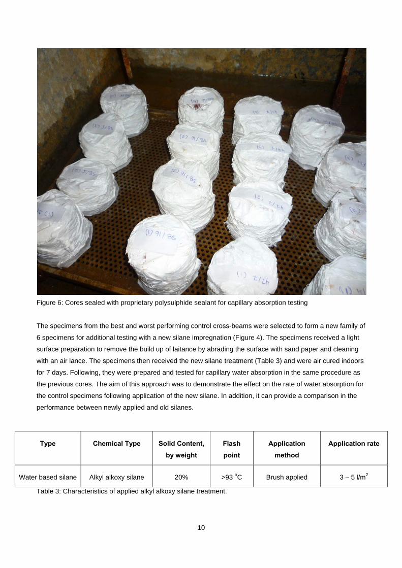
The specimens were placed with their silane treated surface facing down in a layer of water no deeper than 5
mm (Figure 6). Their weights were recorded at 0, 5, 15, 30 minutes and thereafter every 30 minutes over a
total period of 4 hours.
10
Figure 6: Cores sealed with proprietary polysulphide sealant for capillary absorption testing
The specimens from the best and worst performing control cross-beams were selected to form a new family of
6 specimens for additional testing with a new silane impregnation (Figure 4). The specimens received a light
surface preparation to remove the build up of laitance by abrading the surface with sand paper and cleaning
with an air lance. The specimens then received the new silane treatment (Table 3) and were air cured indoors
for 7 days. Following, they were prepared and tested for capillary water absorption in the same procedure as
the previous cores. The aim of this approach was to demonstrate the effect on the rate of water absorption for
the control specimens following application of the new silane. In addition, it can provide a comparison in the
performance between newly applied and old silanes.
Table 3: Characteristics of applied alkyl alkoxy silane treatment.
Type Chemical Type Solid Content,
by weight
Flash
point
Application
method
Application rate
Water based silane Alkyl alkoxy silane 20% >93 oC Brush applied 3 – 5 l/m2
11
The results for all the testing are expressed as a percentage of net weight gain for each core which is used to
calculate rate of absorption (i.e. equation 1) and sorptivity (i.e. equation 2).
3. DATA ANALYSIS
This section describes the data obtained and discusses the results of the tests on the original and on the
newly applied silane treatments, together with their statistical significance.
3.1 Original Silane Treatment
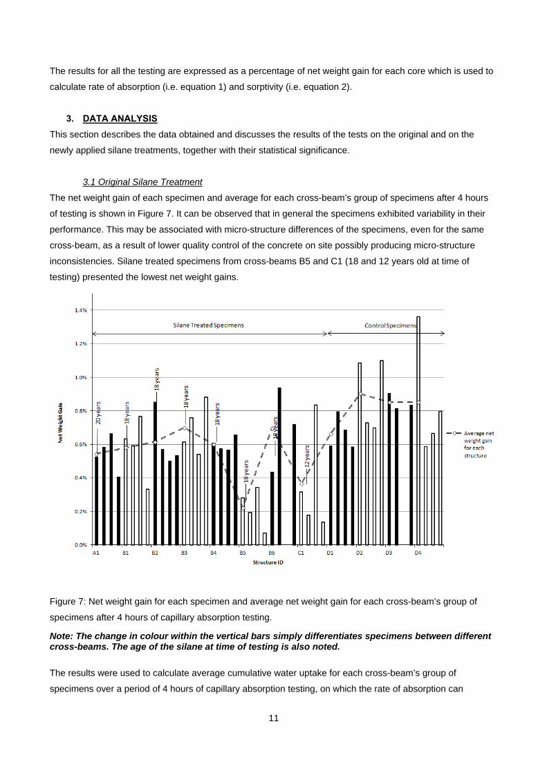
The net weight gain of each specimen and average for each cross-beam’s group of specimens after 4 hours
of testing is shown in Figure 7. It can be observed that in general the specimens exhibited variability in their
performance. This may be associated with micro-structure differences of the specimens, even for the same
cross-beam, as a result of lower quality control of the concrete on site possibly producing micro-structure
inconsistencies. Silane treated specimens from cross-beams B5 and C1 (18 and 12 years old at time of
testing) presented the lowest net weight gains.
Figure 7: Net weight gain for each specimen and average net weight gain for each cross-beam’s group of
specimens after 4 hours of capillary absorption testing.
Note: The change in colour within the vertical bars simply differentiates specimens between different cross-beams. The age of the silane at time of testing is also noted.
The results were used to calculate average cumulative water uptake for each cross-beam’s group of
specimens over a period of 4 hours of capillary absorption testing, on which the rate of absorption can
12
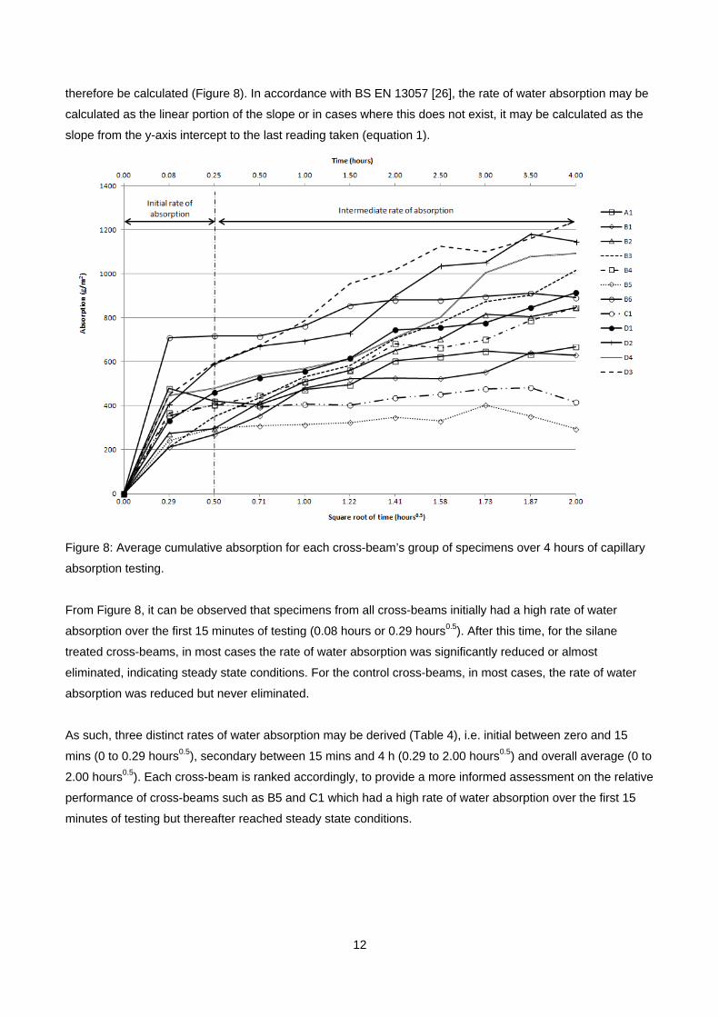
therefore be calculated (Figure 8). In accordance with BS EN 13057 [26], the rate of water absorption may be
calculated as the linear portion of the slope or in cases where this does not exist, it may be calculated as the
slope from the y-axis intercept to the last reading taken (equation 1).
Figure 8: Average cumulative absorption for each cross-beam’s group of specimens over 4 hours of capillary
absorption testing.
From Figure 8, it can be observed that specimens from all cross-beams initially had a high rate of water
absorption over the first 15 minutes of testing (0.08 hours or 0.29 hours0.5). After this time, for the silane
treated cross-beams, in most cases the rate of water absorption was significantly reduced or almost
eliminated, indicating steady state conditions. For the control cross-beams, in most cases, the rate of water
absorption was reduced but never eliminated.
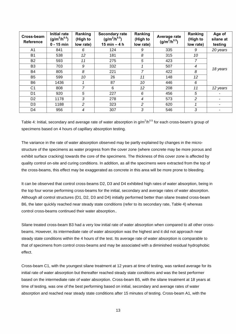
As such, three distinct rates of water absorption may be derived (Table 4), i.e. initial between zero and 15
mins (0 to 0.29 hours0.5), secondary between 15 mins and 4 h (0.29 to 2.00 hours0.5) and overall average (0 to
2.00 hours0.5). Each cross-beam is ranked accordingly, to provide a more informed assessment on the relative
performance of cross-beams such as B5 and C1 which had a high rate of water absorption over the first 15
minutes of testing but thereafter reached steady state conditions.
13
Table 4: Initial, secondary and average rate of water absorption in g/m2/h0.5 for each cross-beam’s group of
specimens based on 4 hours of capillary absorption testing.
The variance in the rate of water absorption observed may be partly explained by changes in the micro-
structure of the specimens as water progress from the cover zone (where concrete may be more porous and
exhibit surface cracking) towards the core of the specimens. The thickness of this cover zone is affected by
quality control on-site and curing conditions. In addition, as all the specimens were extracted from the top of
the cross-beams, this effect may be exaggerated as concrete in this area will be more prone to bleeding.
It can be observed that control cross-beams D2, D3 and D4 exhibited high rates of water absorption, being in
the top four worse performing cross-beams for the initial, secondary and average rates of water absorption.
Although all control structures (D1, D2, D3 and D4) initially performed better than silane treated cross-beam
B6, the later quickly reached near steady state conditions (refer to its secondary rate, Table 4) whereas
control cross-beams continued their water absorption..
Silane treated cross-beam B3 had a very low initial rate of water absorption when compared to all other cross-
beams. However, its intermediate rate of water absorption was the highest and it did not approach near
steady state conditions within the 4 hours of the test. Its average rate of water absorption is comparable to
that of specimens from control cross-beams and may be associated with a diminished residual hydrophobic
effect.
Cross-beam C1, with the youngest silane treatment at 12 years at time of testing, was ranked average for its
initial rate of water absorption but thereafter reached steady state conditions and was the best performer
based on the intermediate rate of water absorption. Cross-beam B5, with the silane treatment at 18 years at
time of testing, was one of the best performing based on initial, secondary and average rates of water
absorption and reached near steady state conditions after 15 minutes of testing. Cross-beam A1, with the
Cross-beam Reference
Initial rate (g/m2/h0.5) 0 - 15 min
Ranking (High to low rate)
Secondary rate (g/m2/h0.5)
15 min – 4 h
Ranking (High to low rate)
Average rate (g/m2/h0.5)
Ranking (High to low rate)
Age of silane at testing
A1 841 6 124 9 335 9 20 years B1 538 12 181 8 315 10
18 years
B2 593 11 275 5 423 7 B3 703 9 332 1 507 4 B4 805 8 221 7 422 8 B5 599 10 26 11 148 12 B6 1436 1 87 10 446 6 C1 808 7 6 12 208 11 12 years D1 920 5 227 6 456 5 - D2 1178 3 278 4 573 2 - D3 1188 2 323 2 620 1 - D4 956 4 307 3 546 3 -
14
oldest silane treatment at 20 years at time of testing, was one of the best performing silane treated cross-
beams.
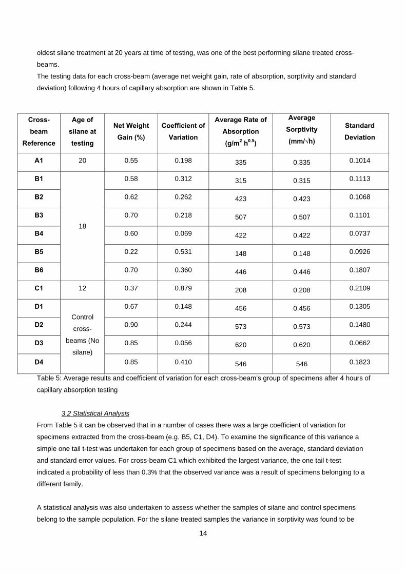
The testing data for each cross-beam (average net weight gain, rate of absorption, sorptivity and standard
deviation) following 4 hours of capillary absorption are shown in Table 5.
Table 5: Average results and coefficient of variation for each cross-beam’s group of specimens after 4 hours of
capillary absorption testing
3.2 Statistical Analysis
From Table 5 it can be observed that in a number of cases there was a large coefficient of variation for
specimens extracted from the cross-beam (e.g. B5, C1, D4). To examine the significance of this variance a
simple one tail t-test was undertaken for each group of specimens based on the average, standard deviation
and standard error values. For cross-beam C1 which exhibited the largest variance, the one tail t-test
indicated a probability of less than 0.3% that the observed variance was a result of specimens belonging to a
different family.
A statistical analysis was also undertaken to assess whether the samples of silane and control specimens
belong to the sample population. For the silane treated samples the variance in sorptivity was found to be
Cross-
beam
Reference
Age of
silane at
testing
Net Weight
Gain (%)
Coefficient of
Variation
Average Rate of
Absorption
(g/m2 h0.5)
Average
Sorptivity
(mm/√h)
Standard
Deviation
A1 20 0.55 0.198 335 0.335 0.1014
B1
18
0.58 0.312 315 0.315 0.1113
B2 0.62 0.262 423 0.423 0.1068
B3 0.70 0.218 507 0.507 0.1101
B4 0.60 0.069 422 0.422 0.0737
B5 0.22 0.531 148 0.148 0.0926
B6 0.70 0.360 446 0.446 0.1807
C1 12 0.37 0.879 208 0.208 0.2109
D1
Control
cross-
beams (No
silane)
0.67 0.148 456 0.456 0.1305
D2 0.90 0.244 573 0.573 0.1480
D3 0.85 0.056 620 0.620 0.0662
D4 0.85 0.410 546 546 0.1823
15
0.0146 mm2 h-1 and for the control samples 0.0075 mm2 h-1. As there was a significant difference between
these values the one tail t-test for unequal variances was used. The test yielded a probability of less than 3%
that the observed difference between the variance of the two samples occurring due to random effects, such
as the choice of sample. As such, it is highly unlikely that there is no difference between the populations and
therefore the silane treatment has an effect.
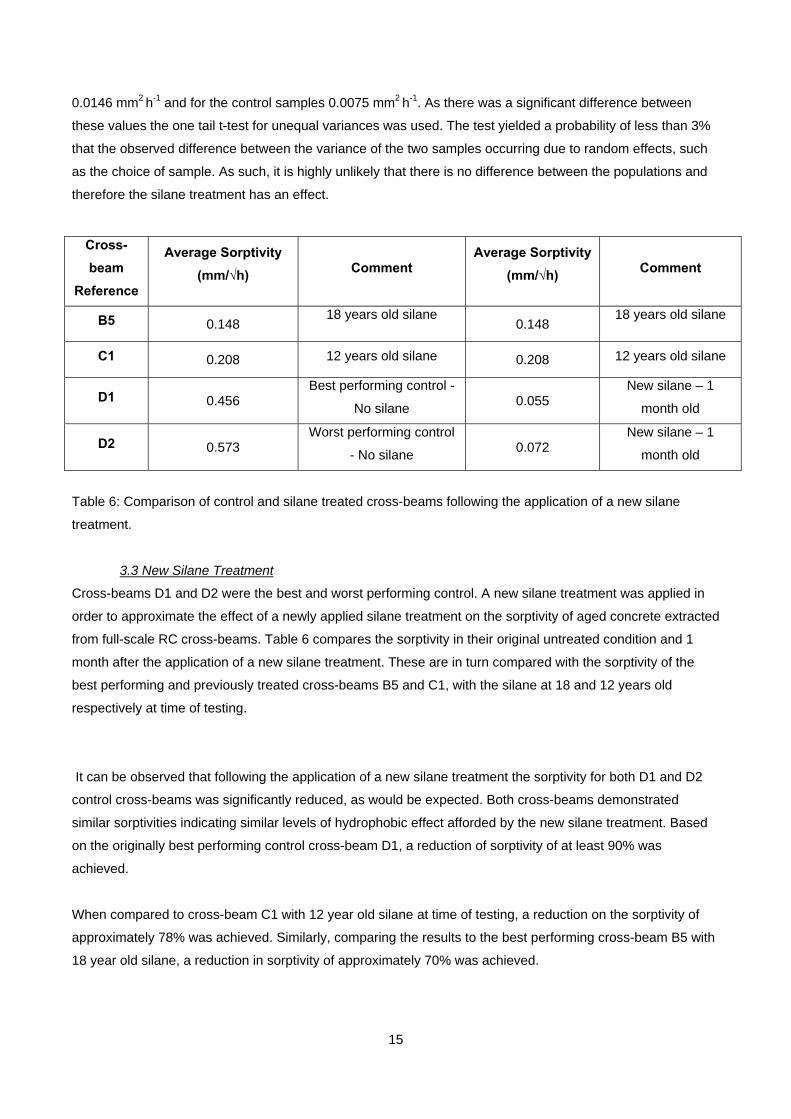
Table 6: Comparison of control and silane treated cross-beams following the application of a new silane
treatment.
3.3 New Silane Treatment
Cross-beams D1 and D2 were the best and worst performing control. A new silane treatment was applied in
order to approximate the effect of a newly applied silane treatment on the sorptivity of aged concrete extracted
from full-scale RC cross-beams. Table 6 compares the sorptivity in their original untreated condition and 1
month after the application of a new silane treatment. These are in turn compared with the sorptivity of the
best performing and previously treated cross-beams B5 and C1, with the silane at 18 and 12 years old
respectively at time of testing.
It can be observed that following the application of a new silane treatment the sorptivity for both D1 and D2
control cross-beams was significantly reduced, as would be expected. Both cross-beams demonstrated
similar sorptivities indicating similar levels of hydrophobic effect afforded by the new silane treatment. Based
on the originally best performing control cross-beam D1, a reduction of sorptivity of at least 90% was
achieved.
When compared to cross-beam C1 with 12 year old silane at time of testing, a reduction on the sorptivity of
approximately 78% was achieved. Similarly, comparing the results to the best performing cross-beam B5 with
18 year old silane, a reduction in sorptivity of approximately 70% was achieved.
Cross-
beam
Reference
Average Sorptivity
(mm/√h) Comment
Average Sorptivity
(mm/√h) Comment
B5 0.148 18 years old silane
0.148 18 years old silane
C1 0.208 12 years old silane 0.208 12 years old silane
D1 0.456 Best performing control -
No silane 0.055
New silane – 1
month old
D2 0.573 Worst performing control
- No silane 0.072
New silane – 1
month old
16
The results may be associated with a reduction in the hydrophobic effect of silanes over time. In addition, the
new silane treatment was applied in a laboratory environment under strict quality control conditions as
opposed to site conditions where a greater variability would be expected to exist when applying surface
treatments to large areas. Furthermore, the new silane treatment is a different proprietary product than the
original, as the latter is no longer available, which, albeit of similar chemical composition, may also produce
performance variations.
5. DISCUSSION
The results suggest that the silane treated specimens exhibited a residual protective effect even after 20
years of service life. Specimens from cross-beams B5 and C1 (18 and 20 years old respectively at time
testing) were overall the best performing silane treated specimens. In particular, specimens from cross-beam
C1 - which had had the most recent application - outperformed all specimens except from cross-beam B5.
Possible reasons for the difference in performance between specimens of silane treated cross-beams include
time dependant effects such as weathering, surface preparation, application rates, environmental conditions
at the time of application and differences in the quality of the concrete. Unfortunately, no historical records
exist providing these details.
The average water absorption of the specimens (Figure 8) was found to have a fluctuating rate throughout the
duration of the test. This is not uncommon, especially when dealing with specimens extracted from full-scale
structures [22]. The variability of concrete within site structures will generally be greater than that of laboratory
cast specimens. The specimens for this study were extracted from the top of the RC cross-beams an area
where concrete is predisposed to bleeding and segregation which can give rise to inconsistencies of the cover
zone.
The application of a new silane treatment had a considerable hydrophobic effect on the properties of the
specimens tested. Specimens from control cross-beams D1 and D2 demonstrated a reduction in their
sorptivity of at least 90% following the application of a new silane impregnation. Comparing the performance
of the newly silane treated specimens with that from previously treated cross-beams such as B5 and C1
provides a baseline of the likely hydrophobic effect of this type of silane on the cross-beams when they were
first applied.
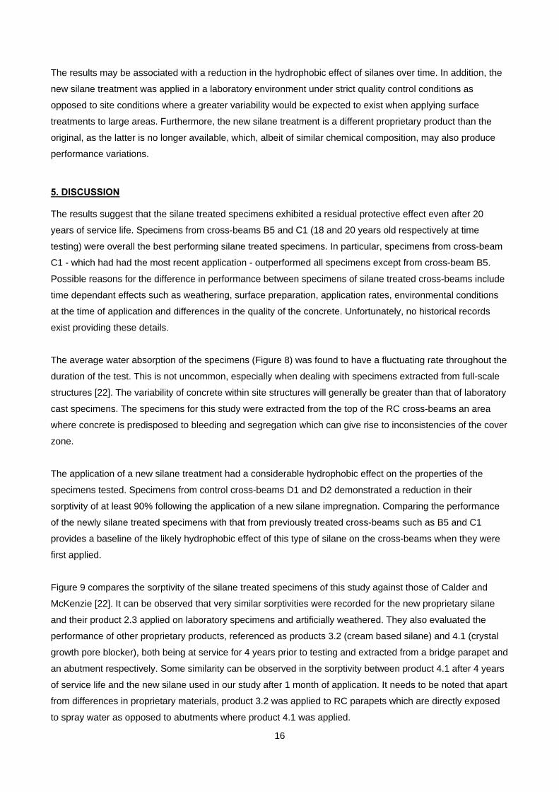
Figure 9 compares the sorptivity of the silane treated specimens of this study against those of Calder and
McKenzie [22]. It can be observed that very similar sorptivities were recorded for the new proprietary silane
and their product 2.3 applied on laboratory specimens and artificially weathered. They also evaluated the
performance of other proprietary products, referenced as products 3.2 (cream based silane) and 4.1 (crystal
growth pore blocker), both being at service for 4 years prior to testing and extracted from a bridge parapet and
an abutment respectively. Some similarity can be observed in the sorptivity between product 4.1 after 4 years
of service life and the new silane used in our study after 1 month of application. It needs to be noted that apart
from differences in proprietary materials, product 3.2 was applied to RC parapets which are directly exposed
to spray water as opposed to abutments where product 4.1 was applied.
17
Figure 9: Comparison of the sorptivity of silane treated specimens examined in the study against
the sorptivity of specimens from Calder and McKenzie [22].
Polder and de Vries [19] also undertook an assessment on the performance of silane treated specimens
following 5 years of exposure to an outdoor environment in the Netherlands. However their results are not
directly comparable as they obtained readings at approximately daily intervals with no readings in the first 4
hours as in the present work. Schueremans et al. [20] examined the performance of silanes from samples
extracted from a full-scale RC quay wall following 12 years of service based on chloride ion concentration.
Rodum and Lindland [29] undertook similar investigations with a number of proprietary products applied to a
RC quay wall in Norway, measuring chloride content at various depths over a period of 10 years. Although
both of those studies [20, 29] demonstrated the long-term performance of silane impregnations it is not
possible to provide a direct comparison with the results of the present work.
The published data on the long-term performance of silane treatments from full-scale RC structures remains
scarce. In addition, differences were found on the sampling, testing and reporting methods which hinders
comparisons between the studies. Additional research is required in order to develop time dependent
relationships on the performance of various proprietary silane products.
6. CONCLUSIONS
Overall, there is very little published empirical evidence that provides insight into the durability of silane
treatments and their long-term residual protection (i.e. following at least 10 years of service). Such a gap in
knowledge is undesirable given the scale of infrastructure treated with hydrophobic treatments such as
silanes. From the results the following can be concluded:
18
All the treated cross-beams demonstrated that the silane impregnation still provides a residual
hydrophobic effect, even with the oldest application from 20 years ago. Statistical analysis indicated
with at least 97% confidence that the variance observed between the silane treated and control
specimens was due to a residual protective effect.
In all but one cross-beam, the most recent silane treated specimens outperformed the other older
silane treated specimens, suggesting that there is a relationship between degradation of the silane
impregnation and duration of environmental exposure..
Silane impregnations should be considered when determining the corrosion management strategy of
a RC structure. Treatments as old as 20 years can still be present and offer a residual protective
effect. Their presence and effectiveness can be evaluated by extracting cores and testing them in the
laboratory by capillary absorption testing.
REFERENCES
[1] Concrete Society. Technical Report 31, Permeability testing of site concrete. Surrey, UK, 2008.
[2] Kropp J., Hilsdorf H.K. RILEM Report 12, Performance criteria for concrete durability, Taylor and Francis,
Oxford, UK, 1995.
[3] Ungricht H., Wasserhaushalt und Chlorideintrag in Beton – Einfulls der Exposition und der
Betonzusammensetzung, Ph. D. Thesis (In German), Universities of Zurich and Basel, 2004.
[4] Basheer P.A.M., Basheer L., Cleland D.J., Long A.E. Surface treatments for concrete: assessment
methods and reported performance, Const. Build Mat 1997; 11:413–429.
[5] Ibrahim M., Al-Gahtani S., Maslehuddin M. Almusallam A.A. Effectiveness of concrete surface treatment
materials in reducing chloride-induced reinforcement corrosion, Const. Build Mat 1997; 11:443–451.
[6] Vries J., Polder R.B. Hydrophobic treatment of concrete, Const. Build Mat 1997; 11:259 -265.
[7] Almusallam A.A., Khan F.M., Dulajan S.U. Al-Amoudi O.S.B. Effectiveness of surface coatings in
improving concrete durability, Cem Concr Compos 2003; 25:381 – 473.
[8] Yang C.C., Wang L.C. Weng T.L. Using charge passed and total chloride content to assess the effect of
penetrating silane sealer on the transport properties of concrete, Mater Chem Phys 2004; 85: 238–244.
[9] Medeiros M.H.F. Helene P. Efficacy of surface hydrophobic agents in reducing water and chloride ion
penetration in concrete, Mater Struct 2008; 41:59–71.
[10] Medeiros M.H.F. Helene P. Surface treatment of reinforced concrete in marine environment: Influence on
chloride diffusion coefficient and capillary water absorption, Const. Build Mat 2009; 23:1476–1484.
[11] Concrete Society, Technical Report 50, Guide to surface treatments for protection and enhancement of
concrete, Surrey, UK, 1997.
[12] Pfeifer D.W. Scali J. Concrete Sealers for Protection of Bridge Structures, Department of Transportation,
NCHRP 244, Washington DC, 1981.
[13] Thompson J.L., Silsbee M.R., Gill P.M. Scheetz B.E., Characterization of silicate sealers on concrete,
Cem Concr Res 1997; 27:1561–1567.
[14] Delucchi M., Barbucci A. Cerisola G. Study of the physico-chemical properties of organic coatings for
concrete degradation control, Const. Build Mat 1997; 11:365–371.
19
[15] Seneviratne A.M.G., Sergi G. Page C.L. Performance characteristics of surface coatings applied to
concrete for control of reinforcement corrosion, Const. Build Mat 2000; 14:55–59.
[16] Al-Zahrani M.M., Al-Dulaijan S.U., Ibrahim M., Saricimen H. Sharif F.M. Effect of waterproofing coatings
on steel reinforcement corrosion and physical properties of concrete, Cem Concr Compos 2002; 24:127–137.
[17] Moon H.Y., Shin D.G. Choi D.S. Evaluation of the durability of mortar and concrete applied with inorganic
coating material and surface treatment system, Const. Build Mat 2007; 21:362–369.
[18] Woo RSC, Zhu H, Chow MMK, Leung CKY and Jang-Kyo K 2008, Barrier performance of silane-clay
nanocomposite coatings on concrete structure, Compos Sci Tech 2008; 68:2828–2836.
[19] Polder R.B. de Vries H. Prevention of reinforcement corrosion by hydrophobic treatment of concrete,
Heron 2001; 46:227–238.
[20] Schueremans L., Gemert D.V. Giessler S. Chloride penetration in RC-structures in marine environment-
Long term assessment of a preventative hydrophobic treatment, Const. Build Mat 2007; 21:1238–1249.
[21] Calder A., Anderson N. and McKenzie M. Survey of impregnated structures. Published Project Report
136. Transportation Research Laboratory; 2006.
[22] Calder A. and McKenzie M. Performance of impregnants. Published Project Report 362. Transportation
Research Laboratory; 2008.
[23] Christodoulou C., Goodier C., Austin S., Glass G. Webb J., Assessing the long-term durability of silanes
on reinforced concrete structures, 1st International Congress on Durability of Concrete, Trondheim, Norway;
2012, ISBN 978-82-8208-031-6.
[24] Glass G.K. Buenfeld N.R., Chloride-induced corrosion of steel in concrete, Prog Struct Eng Mat 2000;
2:448–458.
[25] Austin S.A. Al-Kindy A.A., Air permeability versus sorptivity: effects of field curing on cover concrete after
one year of field exposure, Mag Concr Res 2000; 52:17–24.
[26] British Standards Institution, BS EN 13057:2002, Products and systems for the protection and repair of
concrete structures – Test methods – Determination of resistance of capillary absorption, London: BSI; 2002.
[27] British Standards Institution, BS 1881-122:1983, Method for determination of water absorption, London:
BSI; 1983.
[28] Hall C., Water sorptivity of mortars and concrete, a review. Mag Concr Res 1989; 41:51 – 61.
[29] Rodum E. and Lindland J. Effect of different surface treatment products after 10 years of field exposure,
IN: Proceedings of the 1st International Congress on Durability of Concrete, Trondheim, Norway, 17 - 21 June
2012, ISBN 978-82-8208-031-6.
ACKNOWLEDGEMENTS
The authors would like to thank AECOM, the EPSRC (through the Centre for Innovative and Collaborative
Engineering at Loughborough University) and the Highways Agency for their commercial and financial
support. This work was funded by the Engineering and Physical Sciences Research Council (grant no.
EP/G037272/1).