Embed Size (px)
Citation preview

54 TRANSPORTA T/ON RESEARCH RECORD 1367
Long-Span Nested W-Beam Guardrails over Low-Fill Culverts
KING K. MAK, RoGER P. BLIGH, DoN J. GRIPNE, AND
CHARLES F. MCDEVITT
A problem arises when it is necessary to continue a roadside guardrail across a low-fill box or pipe culvert. Full embedment of the guardrail posts is not possible over the culvert because of the shallow soil cover. Previous crash testing has demonstrated that posts with short embedment depths can be pulled out from the ground and subsequently fall into the path of the vehicle's tires, resulting in snagging or vaulting of the vehicle. For steelpost guardrails, one approach that has been successfully tested is bolting of the base plates of the short steel posts to the top of the box culvert. However, this design is not applicable to woodpost guardrail systems unless the posts are replaced with steel posts for the segment over the low-fill box culvert. This design also requires specially fabricated steel posts and additional labor for installation , resulting in considerably higher installation and maintenance costs. The results of a study to develop a design that is suitable for use with wood-post guardrail systems over low-fill culverts are summarized here. A computer simulation study was conducted to evaluate various alternative designs. The best design was then further evaluated through full-scale crash testing . The final design that was developed and successfully crash tested has no shallow embedment posts over the culvert and uses a nested W-beam rail to span the culvert. The design was tested for span lengths of 12 ft 6 in . (3.81 m) and 18 ft 9 in. (5.72 m). The additional costs associated with implementing this system are relatively low, consisting of two or three 12.5-ft (3.81-m) sections of W-beam rail elements and a little more labor. It is believed that the same design can be used for steel-post guardrail systems over low-fill culverts.
Roadside guardrails are often used in conjunction with culverts to prevent errant vehicles from running off the edge of the culvert. A problem arises when a roadside guardrail must continue across a low-fill culvert. Full embedment of the guardrail posts is not possible over the culvert because of the shallow soil cover. Previous crash testing has demonstrated that posts with short embedment depths can be pulled out from the ground and subsequently impacted by the vehicle's tire, which could result in snagging or vaulting of the vehicle , with potentially disastrous results (J) .
For a steel-post guardrail system, one design that has been successfully crash tested involves welding base plates to the short steel posts and then bolting them to the top of the concrete box culvert (J) . This eliminates the potential for the short posts to be pulled out from the ground and increases
K. K. Mak and R. P. Bligh, Texas Transportation Institute , Texas A&M University System, College Station, Tex. 77843-3135. D. 1. Gripne, Washington State Department of Transportation, Transportation Building, Olympia , Wash. 98504. C. F. McDevitt , Federal Highway Administration , Turner-Fairbank Highway Research Center, 6300 Georgetown Pike , Room T204, McLean, Va. 22101.
their load-carrying capacity. To use this design for wood-post guardrail systems, steel posts must be used instead of wood for the barrier segment over the low-fill box culvert. This design also requires specially fabricated steel posts and additional labor for installation, resulting in considerably higher installation and maintenance costs .
A study was conducted at the Texas Transportation Institute to develop a design that is suitable for use with woodpost guardrail systems over low-fill culverts. The study was jointly sponsored by the Washington State Department of Transportation and the State of Idaho Transportation Department under a pooled-fund study administered by FHW A (2 -5) . First , a computer simulation study was conducted to evaluate several designs. The best design was then further evaluated through full-scale crash testing. The results of this study are summarized here.
COMPUTER SIMULATION STUDY
Four designs were evaluated in the computer simulation study:
1. Single W-beam guardrail with one short post midspan over culvert,
2. Nested W-beam guardrail with one short post midspan over culvert,
3. Single W-beam guardrail with Jong span across culvert, and
4. Nested W-beam guardrail with long span across culvert.
The culvert was assumed to have a minimum soil cover of 18 in. (45.7 cm). The embedment depth for the one short post midspan over the culvert was also assumed to be 18 in. (45.7 cm). The guardrail system was assumed to be a standard G4(2W) strong-post bl0t:ked-uut W-beam guardrail system, with standard 6-in. x 8-in. x 6-ft (15 .2-cm x 20.3-cm x 1.82-m) wood posts placed on either side of the span that bridged the culvert.
The Barrier VII simulation program (6) was the primary tool used in the evaluation of the alternative guardrail designs. It is a two-dimensional simulation program that models vehicular impacts with deformable barriers. The program employs a sophisticated barrier model that is idealized as an assemblage of discrete structural members possessing geometric and material nonlinearities. The available structural members include beams, cables, posts, springs, columns, links, and damping devices . The vehicle is idealized as a plain rigid body surrounded by a series of discrete inelastic springs.

Mak et al.
The Barrier VII program has been shown to be capable of accurately predicting barrier deflections for a wide variety of flexible barrier designs, even under severe impact conditions. Although it cannot be used directly to evaluate the effect of wheel and post interaction and rail rupture, it can be used to predict their occurrence. The amount of wheel snag can be inferred from the position of the vehicle tire and the deflected position of a post. Rail failure can be predicted by evaluating the maximum strain in the rail and comparing the computed values to the rated ductility.
The impact conditions used for the simulation runs consisted of a 4,500-lb (2,041-kg) vehicle impacting the guardrail at a velocity of 60 mph (96.6 km/hr) and an angle of 25 degrees. This is in accordance with the impact conditions outlined in NCHRP Report 230 (7) for evaluating the structural integrity of longitudinal barrier systems.
More than 200 computer simulation runs were conducted to evaluate the four systems. For each system, the span length (i .e ., spacing over the culvert) was systematically varied in order to identify the maximum safe span length. For each span length, the point of impact was varied along the barrier to allow identification of the critical impact locations. The maximum safe span length for each system was determined using both structural and functional failure criteria. The structural failure criterion was based on how much the rail element yielded . This was quantified in terms of the maximum strain in the rail. A typical W-beam rail has a minimum yield stress of 50 ksi (345 Mpa) and a minimum ductility of 12 percent.
The functional failure criterion was based on the maximum allowable deflection for the rail at a given point (e.g. , a post) . The deflection limit imposed on the guardrails with shallow embedment posts was 24 in. (61 cm) because the short post should remain partially embedded at all times during the impact and should not be pulled completely from the soil. The limit for the systems without short posts was 30 in. (76.2 cm). The deflection limit was based primarily on the values obtained from other strong-post barrier systems that have been successfully tested (8). The designs had to satisfy these evaluation criteria to be considered for further evaluation.
One of many factors that influence the maximum deflection of a barrier system is the number of predicted post failures. In the Barrier VII model, complete failure of a post is assumed if the computed displacement along either of the principal axes exceeds a user-specified limit. This represents separation of the rail from the post or withdrawal of the post from the ground. The post is idealized with elastic/perfectly plastic behavior, hence the post will form a plastic hinge at its base and yield at constant load until the specified limit is reached. Based on results of previous static and dynamic testing of guardrail posts (9-11), a limit of 18 in. ( 45. 7 cm) was used for the standard guardrail post and 14 in. (35.6 cm) for the short post. Note that, in the case of the standard post, the limit is more representative of separation from the rail than of a loss of load-carrying capacity. The short post, on the other hand, experiences a significant reduction in loadcarrying capacity at 14 in . (35.6 cm) as a result of partial withdrawal from the ground and excessive rotation.
Summaries of the simulation results for the four systems evaluated are presented in Table 1. For both systems with one short post over the culvert (Systems 1 and 2), the max-
55
imum deflection exceeds the allowable limit of24 in. (61 cm), even for the shortest simulated span of 10.5 ft (3.2 m).
For System 3, with a long-span single W-beam rail and no shallow embedment posts over the culvert, the maximum rail deflections exceed the allowable limit of 30 in. (76.2 cm) for all span lengths simulated. In addition, the structural limitation of the W-beam rail is exceeded for the 10.5 ft (3.2 m) span length . A 19 percent strain was predicted for the Wbeam rail element, which exceeds the rated minimum ductility of 12 percent, indicating that rupture of the rail element is imminent.
System 4, with a long-span nested W-beam rail and no shallow embedment posts over the culvert, appeared to be the best of the four systems evaluated. The data in Table 1 show that neither the functional nor the structural limitations are exceeded for spans up to 18.5 ft (5 .64 m). Longer span lengths are not recommended because of the increased probability of pocketing on the full-strength system and the probability of the impacting vehicle under- or overriding the rail element.
Additional simulation runs were conducted to determine the minimum length of nested rail required to maintain the structural integrity of the rail. A nested rail has twice the area and, consequently , twice the tensile capacity of a single rail. The single W-beam rail will therefore yield at lower loads and produce more elongation in the rail. Simulation runs were conducted for various lengths of nested rail, and the maximum strains were calculated at the transition point from single to nested rail. The longer the length of the nested rail, the lower the tensile forces at the transition point and, thus, the lower the strain in the single W-beam rail. On the other hand, longer nested rails would mean higher material and labor costs.
The simulation results indicated that a minimum of 25 ft (7 .62 m) of nested W-beam rail should be used in conjunction with the 12.5-ft (3.81-m) span over the culvert. This would require two 12.5-ft (3.81-m) rail sections or one 25-ft (7.62-m) section. The nested rail would span over the culvert and one post span on either side of the culvert. Note that this system would have a splice in the middle of the long span when 12.5-ft (3.81-m) rail sections were used. If this detail is not desirable, three sections of nested rail can be used for a total length of 37.5 ft (11.43 m) of nested rail. One section would span the culvert, and an additional section would be added on either side of the long span. This would place all splice locations at a post , a common feature of standard guardrail design.
For a 18.75-ft (5.72-m) span length, a minimum of 37.5 ft (11.4 m) of nested W-beam rail is required. This would require three 12.5-ft (3.81-m) rail sections. The nested rail would span over the culvert, one post downstream of the culvert, and two posts upstream of the culvert. The long span would require a splice because the W-beam rail would be only 12.5 ft (3.81 m) long. When 25-ft (7.62-m) rail elements are used, two sections would be required for a total nested length of 50 ft (15.2 m). The nested rail would span over the culvert, two posts downstream of the culvert, and three posts upstream of the culvert, with a splice in the long span.
On the basis of the results of the simulation study, the design with a long-span nested W-beam rail and no shallow embedment posts over the culvert was considered the best

56 TRANSPORTATION RESEARCH RECORD 1367
TABLE 1 Summary of Computer Simulation Results
Length of Span (ft)
Maximum Rail Deflection (inl
No. of Posts Failed*
Rail Yielded in Tensjon (Y/N l
Maximum Strain (%)
SYSTEM l SINGLE W-BEAM GUARDRAIL WITH ONE SHORT POST MIDSPAN OVER CULVERT
10.5 12.5 14.5
29.3 31.4 32.7
3 2 2
y y y
8.3 8.9 4.4
SYSTEM 2 NESTED W-BEAM GUARDRAIL WITH ONE SHORT POST MIDSPAN OVER CULVERT
10.5 12.5 14.5 16.5
26 . 1 Zb.l 26.3 27.3
2 2 2 2
y y y y
4.7 0.8 l. 9 2.8
SYSTEM 3 SINGLE W-BEAM GUARDRAIL WITH LONG SPAN ACROSS CULVERT
10.5 12.5 14.5
32 .1 32.2 34.1
2 1 1
y y y
19.0 14.2 7.3
SYSTEM 4 NESTED W-BEAM GUARDRAIL WITH LONG SPAN ACROSS CULVERT
14.5 16.5 18.5
26.6 28.1 28. I
y N N
0.5
* Including the short post for systems 1 and 2.
design and was recommended for further evaluation under full-scale crash testing.
FULL-SCALE CRASH TESTING
The long-span nested W-beam guardrail design with no shallow embedment post over the culvert was tested for span lengths of 12.5 ft (3.81 m) (Test 7147-2) and 18.75 ft (5.72 m) (Test 7147-5). The crash test procedures and evaluation criteria were in accordance with requirements outlined in NCHRP Report 230 (7). The results of the two crash tests are summarized in Table 2; the tests are described briefly here.
Test 7147-2
The test installation was 150-ft- (45.7-m-) long and included 87.5 ft (26.7 m) of standard G4(2W) strong-post, blockedout, W-beam wood post guardrail, a 25-ft (7.6-m) turneddown end anchorage on the downstream end , and a 37.5-ft (11.4-m) breakaway cable terminal (BCT) anchorage on the upstream end. The standard guardrail installation included 6-in. x 8-in. x 6-ft (15.2-cm x 20.3-cm x 1.82-m) wood posts
0
with 6-in. x 8-in. x 14-in. (15.2-cm x 20.3-cm x 25 .6-
cm) wood blockouts, which were spaced 6 ft 3 in. (1.91 m) center to center. The W-beam rail elements used were 12 gauge galvanized steel sections , 12 ft 6 in. (3 .81 m) in length.
As shown in Figure 1, a 12-ft 6-in . (3.81-m) span was constructed in the center of the test installation to simulate the long clear span over a low-fill culvert. The minimum length of 25 ft (7.62 m) of nested W-beam rail was used , which allowed for nested rail over the culvert and one post span on either side of the culvert. Since 12-ft 6-in. (3.8-m) W-beam rail elements were used, the splice in the 25 ft (7.62 m) of nested rail was in the middle of the long span instead of at a post. Photographs of the completed test installation are shown in Figure 2.
A 1981 Cadillac Fleetwood was used for the crash test. The empty weight of the vehicle was 4,500 lb (2,043 kg), and its test weight was 4,670 lb (2 ,120 kg). An Alderson Research Laboratories Hybrid II 50th percentile male anthropometric dummy was placed in the driver's seat and restrained with lap and shoulder belts . The vehicle impacted the barrier approximately 1 ft (30.5 cm) downstream from Post 12 (upstream post for the long span over the simulated culvert) at a speed of 62.7 mi/hr (100.9 km/hr) and an angle of 24.5 degrees.
Note that the impact point was selected to produce maximum barrier dynamic deflection and maximum potential for pocketing and wheel snagging at the downstream post of the long span (Post 13) . The impact point was not intended to

TABLE 2 Summary of Test Results
S(!an Length
Descrjptjon
Test Vehicle
Test Weight, lb (kg)
Impact Speed, mi/h (km/h)
Impact Angle, deg.
Point of Impact, ft (m) Downstream of Upstream Post of Long Span
Exit Speed, mi/h (km/h)
Exit Angle, deg.
Velocity Change 1, mi/h (km/h)
Occupant Impact Velocity2
Longitudinal, ft/s (m/s) Lateral, ft/s (m/s)
Occupant Ridedown Acceleration2
Longitudinal, g Lateral, g
Length of Rail Contact, ft (m)
Maximum Dynamic Rail Deflection, ft (m)
Maximum Permanent Deformation, in (cm)
Maximum Vehicle Crush, in (cm)
12 ft 6 in !Jest 7147-21
1981 Cadillac Fleetwood
4670 (2120)
62.7 (100.9)
24.5
1.0 (0.31)
42.2 (67.9)
11. 0
20.5 (33.0)
17.8 (5.4) 15.9 (4.8)
- 6.5 12.9
23. 5 (7. 2)
3.1 (0.9}
29.0 (73. 7)
13.0 (33.0)
18 ft 9 in (Test. 7l47 -5l
1982 Oldsmobile Regency 98
4670 (2120)
60.9 (98.0)
25. 1
2.9 (0.88)
44.2 (71.1}
10.4
16.7 (26.9)
14.7 (4.5) 14.2 (4.3)
- 3.5 9.7
25.0 (7 .6)
3.2 (0.9)
30.0 (76. 2)
8.0 (20.3)
Notes. The velocity change was higher than the recommended value of 15 mi/h ( 24, 1 km/h) in both tests, but the vehi c 1 e was judged not to be a hazard to adjacent traffic lanes.
According to NCHRP Report 230 guidelines, the occupant risk criteria are not applicable for 4,500-lb passenger car crash tests.
3 12'-6" sections of W-beam
2 12'-6" 2 12'-6" sections of sections of
Nested W-beam W-beam
I- 25'-0'" I 37'-0' 125'-0'" 1 25'-0'" I 37'-fl' ----I t I! I 8 I A! B ! I ft! Q ! ! I 8~ 2' offse~ I 2._ -n I BCT Termin:
Turned Down Anchor 1-l 6'J
n ii n a
Long span over simulated box culvert
Impact :1·-1 Po;ot of
~ ~ n n ii n
FIGURE 1 Details of test installation with span length of 12 ft 6 in. for Test 7147-2.
n 1Q
58
FIGURE 2 Photographs of test installation before Test 7147-2.
produce maximum dynamic deflection in the system, which was considered less critical than pocketing and snagging at the downstream post.
The long-span nested W-beam guardrail system with a 12.5-ft (3.81-m) span length performed well in the crash test. The vehicle was smoothly redirected and did not penetrate or go over the guardrail system. There were no detached elements or debris that showed potential for penetrating the occupant compartment or presenting undue hazard to other vehicles. The vehicle remained upright and stable during the impact and after exiting the test installation. Some slight pocketing and tire contact occurred at the downstream post of the long span, but their effects were minor and did not significantly affect the vehicle kinematics or trajectory . The velocity change of 20.5 mi/hr (33.0 km/hr) was higher than the limit of 15 mi/hr (24.1 km/hr) recommended in NCHRP Report 230. However, vehicle trajectory at loss of contact indicates minimal potential for intrusion into adjacent traffic lanes. Therefore, the velocity change criterion is not applicable. It should be noted that the criterion is seldom met in crash tests involving flexible barrier systems.
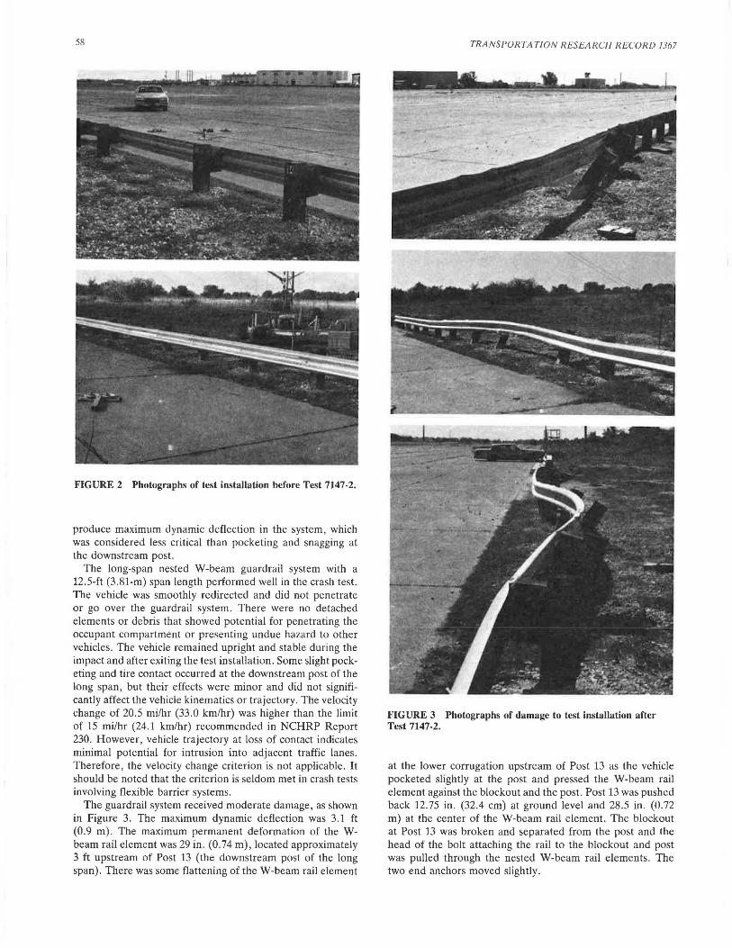
The guardrail system received moderate damage, as shown in Figure 3. The maximum dynamic deflection was 3.1 ft (0 .9 m) . The maximum permanent deformation of the Wbeam rail element was 29 in . (0.74 m), located approximately 3 ft upstream of Post 13 (the downstream post of the long span). There was some flattening of the W-beam rail element
TRANSPORTATION RESEARCH RECORD 1367
FIGURE 3 Photographs of damage to test installation after Test 7147-2.
at the lower corrugation upstream of Post 13 as the vehicle pocketed slightly at the post and pressed the W-beam rail element against the blockout and the post. Post 13 was pushed back 12.75 in. (32.4 cm) at ground level and 28 .5 in. (0.72 m) at the center of the W-beam rail element. The blockout at Post 13 was broken and separated from the post and the head of the bolt attaching the rail to the blockout and post was pulled through the nested W-beam rail elements . The two end anchors moved slightly.

Mak et al.
FIGURE 4 Photographs of damage to vehicle after Test 7147-2.
0.149 s
Test No ......... 7147-2 Date . • . • • • • . . . 09/25/90 Test Installation ...• Washington Nested
W-beam with wood posts Installation Length ... 150 ft (46 m) Max. Dynamic Deflection. 3.1 ft (0.9 m) Max. Perm. Deformation 2.4 ft (0.7 m) Vehicle . . . 1981 Cadillac Vehicle Weight Fleetwood
Test Inertia . . . . 4,500 lb (2,043 kg) Gross Static ..... 4,669 lb (2,120 kg)
Vehicle Damage Classification TAD . . . . . . . . 01FR5 & 01RD4 CDC ......... 01FREK2 & 01RDEW3
Maximum Vehicle Crush . 13.0 in (33.0 cm)
FIGURE 5 Summary of results for Test 7147-2.
59
The vehicle sustained moderate damage to the right side, as shown in Figure 4. The tie rod was bent, and the windshield was broken. There was damage to the bumpers, hood, grill, radiator and fan, right front and rear quarter panels, and right front and rear doors. The wheelbase on the right side was shortened from 121.5 in. (3.09 m) to 116.0 in. (2.95 m). The right front and rear tires and rims were damaged from contact with the posts. Maximum crush of the vehicle was 13.0 in. (33.0 cm) at the right front corner at bumper height. However, essentially no intrusion or deformation of the passenger compartment occurred. Note that much of the damage to the.front of the vehicle was the result of the vehicle impacting the end of a concrete barrier near the end of the vehicle trajectory. It should also be noted that the test vehicle had a fiberglass header panel, which made the damage to the front of the vehicle appear worse than it really was. A summary of the test results is presented in Figure 5.
Test 7147-5
The installation used for this test was similar to that used in Test 7147-2 except for the 18.75-ft (5.48-m) span constructed in the center of the test installation (between Posts 11 and 12) to simulate the long span over a low-fill culvert, as shown in Figure 6. Three 12.5-ft (3.81-m) sections ofnested W-beam were used, for a total length of 37.5 ft (11.43 m), starting from Post 9, extending over the culvert span of 18.75 ft (5. 72 m), and terminating at Post 13. Photographs of the completed test installation are shown in Figure 7.
A 1982 Oldsmobile Regency 98 was used for the crash test. The empty weight of the vehicle was 4,500 lb (2,043 kg), and its test weight was 4,670 lb (2,120 kg). Again, a 50th_ percentile
0.298 s 0.447 s
Impact Speed . . 62 . 7 mi/h (100.9 km/h) Impact Angle . . 24 . 5 degrees Speed at Parallel 49 .4 mi/h (79.5 km/h) Exit Speed . . . 42 . 2 mi/h (67 . 9 km/h) Exit Trajectory . . 11. 0 degrees Vehicle Accelerations
(Max. 0.050-sec Avg) Longitudinal .. -4.5 g Latera 1 . . . . . 7. 1 g
Occupant Impact Velocity Longitudinal .. 17.8 ft/s (5.4 m/s ) Lateral ..... 15.9 ft/s (4.8 m/s)
Occupant Ridedown Accelerations Longitudinal . . -6.5 g Lateral • . . . . 12.9 g

60
Turn ed Down Terminal
3 12'-6" sections of W-beam
3 12'-6" sections of
Nested W-beam
TRANSPORTATION RESEARCH RECORD 1367
1 12'-6" section of
W-beam BCT Terminal
r- 25'-0"
L
L2·
37'-6" ---j ~===~~~~~--JL____f~.....!L~~RIL.._JIR~-li.~.JL-...L __ ~_.....!LR _.JL_...L_JL__Jl~.....!L-~Ri!.-_.ll--,.,Jl.~
37'- 6" - ---'"-- -- 3 7'- 6" -----.Ir 11 2' -6" --1 · ---
offset
1 n [j Li A n ~ 19 18 17 16 15 14
r- 18'-9" ~ Long span over
simulated box culvert
2'-10 1/2" -j r-n A ·~U fi 13 12
? ,.Point
0 u n ~ n n 5 4 3
of Impact
FIGURE 6 Details of test installation with span length of 18 ft 9 in. for Test 7147-S.
FIGURE 7 Photographs of test installation before Test 7147-5.
male anthropometric dummy was placed in the driver's seat and restrained with lap and shoulder belts. The vehicle impacted the guardrail system approximately 2.9 ft (0.9 m) downstream of Post 11 (upstream post for the long span over the simulated culvert) at a speed of 60.9 mi/hr (98.0 km/hr) and an angle of 25.1 degrees. As before, the impact point was selected to produce maximum dynamic deflection and maximum potential for pocketing and wheel snagging at the downstream post of the long span (i .e. , Post 12) .
The 18-ft 9-in. (5 .72 m) long-span nested W-beam guardrail system performed well in the crash test. The vehicle was smoothly redirected and did not penetrate or go over the guardrail system. There were no detached elements or debris that indicated potential for penetrating the occupant compartment or presenting undue hazard to other vehicles. The vehicle remained upright and stable during the impact and after exiting the test installation. Slight pocketing and tire contact occurred at the downstream post of the long span, but their effects were minor and did not significantly affect the vehicle kinematics or trajectory. The velocity change was slightly higher than the recommended limit of 15 mi/hr (24.1 km/hr) , but the vehicle trajectory at loss of contact indicates minimal potential for intrusion into adjacent traffic lanes. The velocity change criterion is therefore not applicable .
The guardrail system received moderate damage, as shown in Figure 8. The maximum dynamic deflection was 3.2 ft (0 .9 m). The maximum permanent deformation of the Wbeam rail element was 30.0 in. (0.76 m), located approximately in the center of the long span. Post 12 was pushed back 16.5 in. (41.9 cm) at ground level and 23 .0 in . (0.58 m) at the center of the W-beam rail element. The blockout at

Mak et ai.
Post 11 was separated from the post and rail elements, and the post was split. No movement occurred at the two end anchors.
As shown in Figure 9, damage sustained by the vehicle was minor, given the severity of the impact. The upper control arm on the right side was damaged. There was damage to the bumpers, hood, grill, right front and rear quarter panels, and right front and rear doors. The wheelbase on the right side was shortened from 119.0 in. (3.02 m) to 117.0 in. (2.97 m). The right front and rear tires and rims were damaged from
FIGURE 8 Photographs of damage to test installation after Test 7147-5.
61
contact with the posts . Maximum crush of the vehicle was 8.0 in. (20.~ cm) at the right front corner at bumper height. However, there was no intrusion in or deformation to the occupant compartment. A summary of the test results is presented in Figure 10.
CONCLUSION
A design suitable for use with wood-post guardrail systems over culverts was developed and successfully crash tested. The design uses a nested W-beam rail to span the culvert and has no shallow embedment posts over the culvert. The design was
FIGURE 9 Photographs of damage to vehicle after Test 7147-5.

62
o. 000 s
Test No. . Date ... Test Installation.
0.149 s
. . . 7147-5
. . . 05/30/91
... Washington Nested W-beam with wood posts
Installation Length ... 150 ft (46 m) Max. Dynamic Deflection. 3.2 ft (1.0 m) Max. Perm. Deformation 2.5 ft (0.8 m) Vehicle . . . 1982 Oldsmobile Vehicle Weight Regency 98
Test Inertia . . . . 4,500 lb (2,043 kg) Gross Static ..... 4,670 lb (2,120 kg)
Vehicle Damage Classification TAD . . . . . . . . 01FR4 &. 01RD3 CDC . . . . . . . . . 01FREK2 &. 01RDEW2
Maximum Vehicle Crush . 8.0 in (20.3 cm)
FIGURE 10 Summary of results for Test 7147-5.
successfully crash tested for span lengths of 12 ft 6 in. (3.81 m) and 18 ft 9 in. (5.72 m). This design resolves problems associated with poor guardrail performance caused by shallow post embedment depths over low-fill culverts. The additional costs associated with implementing this design are relatively low.
Although this long-span nested W-beam guardrail design was developed for wood-post guardrail systems (the sponsoring agencies use wood-post guardrail systems), it is believed that it would also work for steel-post guardrail systems. The strengths of wood and steel posts are generally compatible, and there is no reason to believe that this design would behave differently for a steel-post system. This would be a simpler and less expensive alternative to the design of connecting the bottoms of the posts to the top of the culvert. Thus, this design is recommended for use with both woodpost and steel-post guardrail systems .
This design has been approved by FHW A and adopted by the Washington State Department of Transportation and the State of Idaho Transportation Department for field implementation. It is also being considered for situations in which a span length greater than the standard 6-ft 3-in. (1.91 m) post spacing is required at isolated locations (e.g., ditch lines or concrete drainage aprons).
REFERENCES
1. T. J. Hirsch and D. Beggs. Use of Guardrails on Low Fill Bridge Length Culverts. Research Report 405-2F. Texas Transportation
TRANSPORTATION RESEARCH RECORD 1367
0. 298 s 0.447 s
Impact Speed · . . 60. 9 mi/h (98 . 0 km/h) Impact Angle . . 25 . l degrees Speed at Parallel 48 .6 mi/h (78.2 km/h) Exit Speed . . . 44.2 mi/h (71.l km/h) Exit Trajectory . . 10.4 degrees Vehicle Accelerations
(Max . 0.050-sec Avg) Longitudinal •. - 2.7 g Lateral . . . • • 6 .8 g
Occupant Impact Ve 1 oci ty Longitudinal .. 14.7 ft/s (4. 5 m/s) Lateral ..... 14.2 ft/ s (4 . 3 m/s)
Occupant Ridedown Accelerations Longitudinal . . -3 . 5 g Lateral . . . . . 9. 7 g
Institute, Texas A&M University System, College Station, Aug. 1987.
2. R. P. Bligh and K. K. Mak. Analysis of Guardrail over Low-Fill Culverts. Interim report on Task A, Subtask 1, Contract No . DTFH61-89-C-00089. Texas Transportation Institute, Texas A&M University System, College Station, Sept. 1990.
3. K. K. Mak and W. L. Campise. Test Report No . 7147-2 , Contract No . DTFH61-89-C-00089. Texas Transportation Institute, Texas A&M University System , College Station , Oct. 1990.
4. K. K. Mak and W. L. Campise . Test Report No. 7147-4, Contract No. DTFH61-89-C-00089. Texas Transportation Institute, Texas A&M University System, College Station, June 1991.
5. K. K. Mak and W. L. Campise. Test Report No. 7147-5 , Contract No. DTFH61-89-C-00089. Texas Transportation Institute, Texas A&M University System, College Station, June 1991.
6. G. H. Powell. A Computer Program for Evaluation of Automobile Barrier Systems. Report FHWA-RD-73-51 . FHWA, U.S . Department of Transportation, 1973.
7. J. D . Michie . NCH RP Report 230: Recommended Procedures for the Safety Performance Evaluation of Highway Appurtenances. TRB, National Research Council, Washington, D.C., March 1981.
8. D. L. Sicking, R. P. Bligh, and H. E. Ross , Jr. Optimizalion of Strong Post W-Beam Guardrail. Research Report 1147-lF. Texas Transportation Institute , Texas A&M University System, College Station, Nov. 1988.
9. D. Eggers and T. J. Hirsch . The Effects of Embedmenl Depth, Soil Properties, and Post Type on the Performance of Highway Guardrail Posts. Research Report 405-1. Texas Transportation Institute, Texas A&M University System, College Station, Aug. 1986.
10. M. E. Bronstad, L. R . Calcote, M. H. Ray, and J.B. Mayer. Guardrail-Bridge Rail Transition Design-Volume 1, Research Report. Report FHWA/RD-86/178. FHWA, U.S . Department of Transportation, April 1988.
11. J . F. Dewey et al. A Study of the Soil-Slructure Interaction Behavior of Highway Guardrail Posts. Research Report 343-1. Texas Transportation Institute, Texas A&M University System, College Station, July 1983.