Embed Size (px)
Citation preview

Long Lasting Rigid Pavements
Technical University “Gh. Asachi” Iasi

The Long Life Rigid Pavements The Long Life Rigid Pavements --LLRPLLRP
The concept of The concept of Long Lasting Rigid PavementsLong Lasting Rigid Pavements can can be defined only in conjunction with the world wide be defined only in conjunction with the world wide evolution of modern paving expressed in significant evolution of modern paving expressed in significant changes in changes in thickness design, materials specification, thickness design, materials specification, construction and maintenance technologies construction and maintenance technologies

Long Lasting Rigid Pavements
Significant approaches to get concrete road projects with extSignificant approaches to get concrete road projects with extended life ended life
Increase the specified aggregate sizeIncrease the specified aggregate size from 19 mm to 32 mm /or 15 to from 19 mm to 32 mm /or 15 to 25mm, to improve flexural strength without significant increases25mm, to improve flexural strength without significant increases in in cement content.cement content.
Devise these layers within the oneDevise these layers within the one--slipformed layerslipformed layer rather than a rather than a multilayer approach that might lead to delamination.multilayer approach that might lead to delamination.
Continue to provide incentives to contractorsContinue to provide incentives to contractors to encourage to encourage pavements to be constructed to lower tolerances or to better medpavements to be constructed to lower tolerances or to better mediumium--term performance measures.term performance measures.
Professor RADU ANDREI

The quality of the concrete is a major factor in seeking longThe quality of the concrete is a major factor in seeking long--term performanceterm performance..
Evolution of coefficient of variation data on paving projects from 1975 to 2005 in Australia

Increase of minimum recommended thickness and Increase of minimum recommended thickness and improvements in pavement structural design :improvements in pavement structural design :
Developing Developing more refined thickness design procedure /more refined thickness design procedure /Change from Change from nomographs to nomographs to computer programs and spreadsheet analysiscomputer programs and spreadsheet analysis in order in order to reduce human error.to reduce human error.
Increase the skew to transverse contraction jointsIncrease the skew to transverse contraction joints from 1:6 to 1:10.from 1:6 to 1:10.
Better collection of heavy traffic dataBetter collection of heavy traffic data provided better input into fatigue provided better input into fatigue analysis.analysis.
Minimum base layer thicknessMinimum base layer thickness for different pavement types have been for different pavement types have been introduced in the last years.introduced in the last years.

Improvements in construction requirementsImprovements in construction requirements
Tolerance for thickness and strength was modifiedTolerance for thickness and strength was modified to to ensure that more of the pavement was built above the ensure that more of the pavement was built above the minimum limit rather than an average around the design minimum limit rather than an average around the design requirement.requirement.
Better preparation of materialsBetter preparation of materials, reduce the risk of , reduce the risk of construction.construction.
Significant Significant improvements to the slipform pavers improvements to the slipform pavers and better and better training of staff at all levels conducted prior to construction.training of staff at all levels conducted prior to construction.
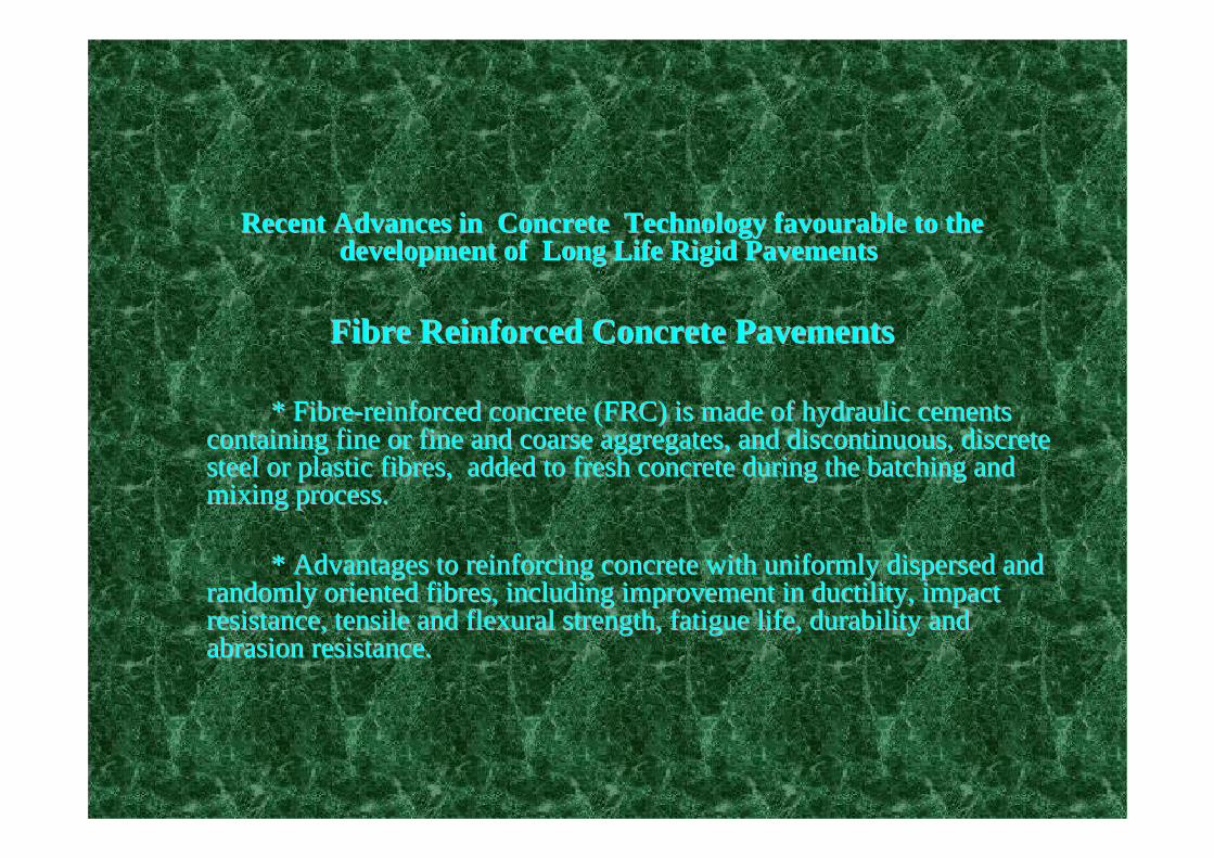
Recent Advances in Concrete Technology favourable to the Recent Advances in Concrete Technology favourable to the development of Long Life Rigid Pavements development of Long Life Rigid Pavements
Fibre Reinforced Concrete PavementsFibre Reinforced Concrete Pavements
* Fibre* Fibre--reinforced concrete (FRC) is made of hydraulic cements reinforced concrete (FRC) is made of hydraulic cements containing fine or fine and coarse aggregates, and discontinuouscontaining fine or fine and coarse aggregates, and discontinuous, discrete , discrete steel or plastic fibres, added to fresh concrete during the batsteel or plastic fibres, added to fresh concrete during the batching and ching and mixing process.mixing process.
* Advantages to reinforcing concrete with uniformly dispersed an* Advantages to reinforcing concrete with uniformly dispersed and d randomly oriented fibres, including improvement in ductility, imrandomly oriented fibres, including improvement in ductility, impact pact resistance, tensile and flexural strength, fatigue life, durabilresistance, tensile and flexural strength, fatigue life, durability and ity and abrasion resistance. abrasion resistance.

Polymer fibre reinforced concrete pavementsPolymer fibre reinforced concrete pavements
Synthetic Fibres for concrete pavements
Polypropylene fibres used in concrete at a rate of at least 0.1% by volume. Concrete containing 1 or 2% by volume of propylene fibres showed deterioration in compression stress-strain response when compared with the control mixture (SHRP Research)

Steel fibre reinforced concrete (SFRC)Steel fibre reinforced concrete (SFRC)
SFRC with steel fibres industrial producedSFRC with steel fibres industrial produced
The most significant effects of incorporating steel fibres in coThe most significant effects of incorporating steel fibres in concrete: ncrete: --delay and control the tensile cracking of concrete delay and control the tensile cracking of concrete --increase resistance to impact and repeated loadingincrease resistance to impact and repeated loading
Steel fibres: with hooks (left) and crimp-shaped (right)

Recent Advances in Concrete Technology favourable to the develRecent Advances in Concrete Technology favourable to the development opment of Long Life Rigid Pavements of Long Life Rigid Pavements
Roller Compacted Concrete (RCC)Roller Compacted Concrete (RCC) Roller compared concrete (RCC), is a Roller compared concrete (RCC), is a
composite material made from the combination of composite material made from the combination of three main constituents: aggregates, water and three main constituents: aggregates, water and binder, that are the same as for conventional binder, that are the same as for conventional concrete, but are mixed with different concrete, but are mixed with different proportioning resulting to a material with proportioning resulting to a material with distinctive properties and behaviourdistinctive properties and behaviour. .

Without wearing course
With wearing course
Roller compacted Cast
Conventional concrete
Cement treated base
RCC
Water content
Flowable fill
Cem
ent c
onte
nt
Distinction between the different types of concrete based on the cement content and water ratio

Options for the LLRP Options for the LLRP structural concepts structural concepts envisaged for the EcoLanes envisaged for the EcoLanes Project by using SFRC and SFRCCProject by using SFRC and SFRCC
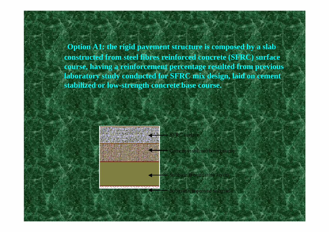
Option A1: the rigid pavement structure is composed by a slab constructed from steel fibres reinforced concrete (SFRC) surfacecourse, having a reinforcement percentage resulted from previouslaboratory study conducted for SFRC mix design, laid on cement stabilized or low-strength concrete base course.
Cement stabilized base course
SFRC surface
Subgrade/improved subgrade
Subbase (Foundation layer)

Option A2: the rigid pavement structure is composed by a slab constructed from steel fibres reinforced concrete (SFRC) surfacecourse, having a reinforcement percentage resulted from previouslaboratory study conducted for SFRC mix design, laid on a relative thin asphalt layer constructed over a base course granular supported by a classic foundation.
Subgrade/improved subgrade
Subbase (Foundation layer)
Granular base course
SFRC surface
Intermediate asphalt layer
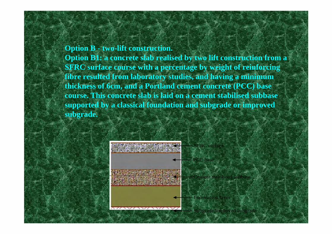
Option B - two-lift construction.Option B1: a concrete slab realised by two lift construction from a SFRC surface course with a percentage by weight of reinforcing fibre resulted from laboratory studies, and having a minimum thickness of 6cm, and a Portland cement concrete (PCC) base course. This concrete slab is laid on a cement stabilised subbase supported by a classical foundation and subgrade or improved subgrade.
Subgrade/improved subgrade
Foundation layer
Cement stabilized subbase
SFRC surface
PCC base
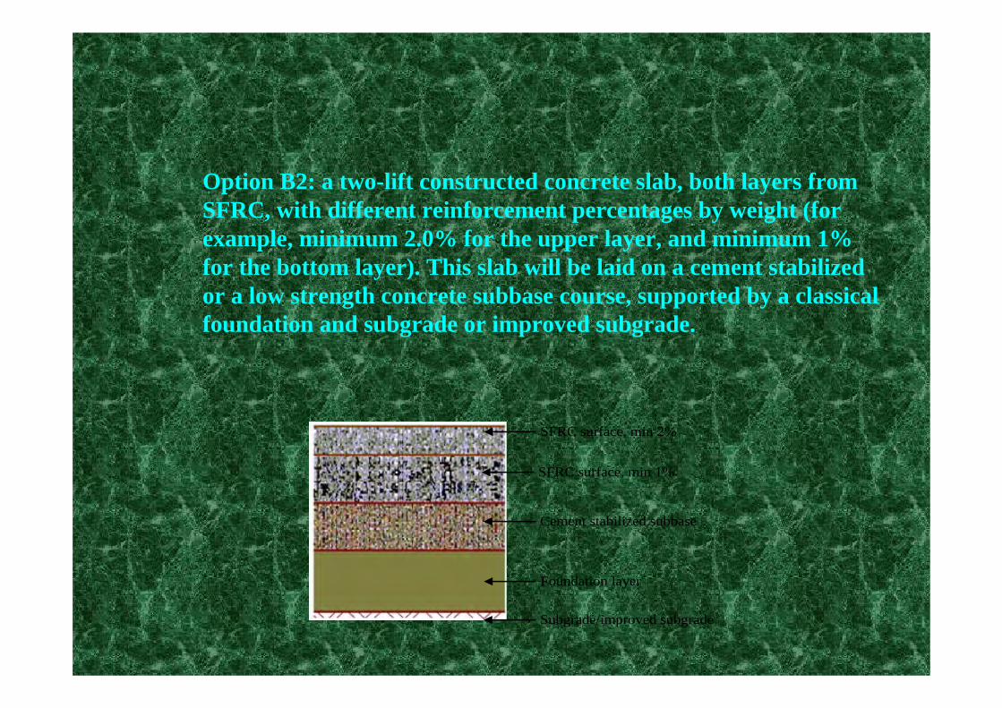
Option B2: a two-lift constructed concrete slab, both layers from SFRC, with different reinforcement percentages by weight (for example, minimum 2.0% for the upper layer, and minimum 1% for the bottom layer). This slab will be laid on a cement stabilized or a low strength concrete subbase course, supported by a classical foundation and subgrade or improved subgrade.
Subgrade/improved subgrade
Foundation layer
Cement stabilized subbase
SFRC surface, min 2%
SFRC surface, min 1%

Option B3: a concrete slab realised from a SFRC surface layer, of a minimum 6 cm thickness and a RCC layer, laid on a granular base course, supported by a classical foundation and a subgrade or improved subgrade.
Subgrade/improved subgrade
Foundation layer
Granular base course
SFRC surface
RCC layer
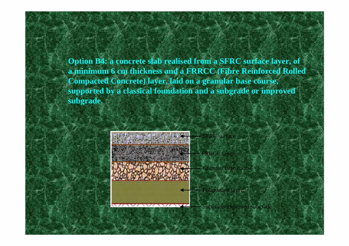
Option B4: a concrete slab realised from a SFRC surface layer, of a minimum 6 cm thickness and a FRRCC (Fibre Reinforced Rolled Compacted Concrete) layer, laid on a granular base course, supported by a classical foundation and a subgrade or improved subgrade.
Subgrade/improved subgrade
Foundation layer
Granular base course
SFRC surface
FRRCC layer

Option C: composite pavement structuresOption C1: a bituminous surface course is laid on a RCC (Rolled Compacted Concrete) base, supported by a granular base course, aclassical foundation, and a subgrade or improved subgrade.
Subgrade/improved subgrade
Foundation layer
Granular base course
Asphalt surface
RCC layer

Option C2: the bituminous surface course is laid on a SFRRCC (Steel Fibre Reinforced Rolled Compacted Concrete) base, supported by a granular base course, a classical foundation, and a subgrade or improved subgrade.
Subgrade/improved subgrade
Foundation layer
Granular base course
Asphalt surface
FRRCC layer

Accelerating Loading Testing - ALT for validation of Long Lasting Rigid Pavements
Accelerated Loading Facility (ALF) - Australian experiment.Objectives:
•to validate and refine the existing fatigue design criteria for plain concrete pavements;
•to investigate the impact of various subbase types on the performance of plain concrete pavements.
Accelerating Loading Test - ALT : Lessons learned from the Australian experiment :
Results:•the dual-tire assembly with 8t loading did not precipitate fatigue cracking and limited the findings from the ALF repetitive loading.
•in terms of sub-base support, the study did confirm that a lean-mix concrete or heavily bound sub-base would perform better than an unbound granular material as a sub-base.
(These results have been taken into consideration by the UT Iasi team in planning the EcoLanes ALT experiment on the circular accelerated track, the rigid pavement structures of all experimental sectors ( 1 to 6) being provided with stabilized sub-base )
Deliverable 3.2
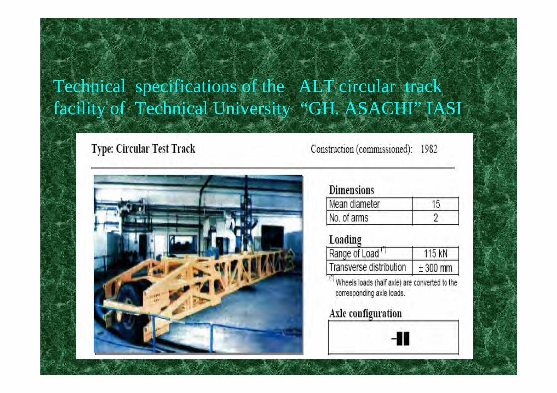
Technical specifications of the ALT circular track facility of Technical University “GH. ASACHI” IASI

Technical specifications of the ALT circular track facility of Technical University “GH. ASACHI” IASI

Options on LLRP experimental sectors constructed and under testing on the ALT circular track facility of Technical University “GH. ASACHI” IASI

26
The actual Ecolanes pavement structures constructed on the ALT circular facility at Technical University “ Gh. Asachi” Iasi
5,5m
5,5m
5,5m
d = 12 m
D = 18 m
71
2
3
4
Legend:1 - P lain Concrete w ithout fibers2, 3, 4 - PC+SRSF5, 6 - RCC+SRSF7 - RCC w ithout fibers
5
6
10,5m
8m
6m
6m
20
15
15
BCR 4,5
Pavem ent structure sector 1
25
15
Pavem ent structure sector 7
10
RCC
25
15
Pavem ent structure sector 6
10
RCC +3% SRSF
25
15
Pavem ent structure sector 5
10
RCC +6% SRSF
20
15
15
Stabilizedballast
PC 4,5 +3% SRSF
Ballast
Subgrade
Pavem ent structure sectors 2, 3 & 4
Stabilizedballast
Stabilizedballast
S tabilizedballast
Stabilizedballast
Ballast
Ballast
BallastBallast
Subgrade
Subgrade
SubgradeSubgrade
27
Accelerated Load Testing of Long Lasting Rigid Pavements
• Two types of steel fiber reinforce concrete has been envisaged to be used for the ALT experiment in the frame theEcolanes project :• PC & SFRC , compacted by vibration;•- SFRCC, compacted by rolling
28
Accelerated Load Testing of Long Lasting Rigid Pavements
PC & SFRC , compacted by vibrationsector 1: unreinforced concrete, dmax=25 mm, l=6 m;
− sectors 2, 3 & 4: SFRC, with 3% fibre SRSF (ADRIA), dmax=16 mm, with different length : 6 m, 8m and 10,5 m

29
Accelerated Load Testing of Long Lasting Rigid Pavements
•The initial planning of the ALT laying out of the experimental sectors, presented during the Brussels meeting has been altered, in order to have the possibility to study also the infuence of the percentage of fibres. Thus , instead of two sectors with different lengths ( 6 m & 10,5 m), have been constructed three sectors ( 5, 6 & 7) having the same length of 5,5 m , but realized with concrete prepared with different percentge of fibers ( 6%, 3% & 0%)

30
Accelerated Load Testing of Long Lasting Rigid Pavements
•As traffic loads will apply directly on the surface of the RCC, in order to keep for the riding surface the same level on the whole ALT circular track, the initial thickness of RCC slabs of 20 cm has been increased to 25 cm.• In case when severe distress may occur at the surface of the slabs during the ALT experiment, will be possible to proceed with the cutting of concrete on a 5cm depth and to replace it with a bituminous layer.•The RCC slabs are placed on a cement stabilized ballast sub-base (h=15 cm) , supported by a ballast foundation (h=10 cm), the total thickness of pavement structures on the ALT track being the same (50 cm).
31
Accelerated Load Testing of Long Lasting Rigid Pavements
•As traffic loads will apply directly on the surface of the RCC, in order to keep for the riding surface the same level on the whole ALT circular track, the initial thickness of RCC slabs of 20 cm has been increased to 25 cm.• In case when severe distress may occur at the surface of the slabs during the ALT experiment, will be possible to proceed with the cutting of concrete on a 5cm depth and to replace it with a bituminous layer.•The RCC slabs are placed on a cement stabilized ballast sub-base (h=15 cm) , supported by a ballast foundation (h=10 cm), the total thickness of pavement structures on the ALT track being the same (50 cm).

32
Accelerated Load Testing of Long Lasting Rigid PavementsThe construction of the various layers of pavement structures on the experimental sectors of the ALT
facility• Earthworks reconstruction/ subgrade• Construction of the ballast fundation layer • Construction of the sub-base from cement stabilized
ballast • Construction of the concrete slabs
- Construction of wet concrete slabs, compacted by vibration (PC)
-Construction of rolled compacted concrete slabs ( RCC)

Transducers and their placement on the ALT circular track

34
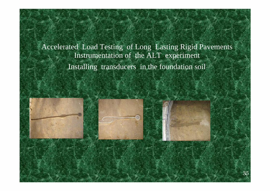
Accelerated Load Testing of Long Lasting Rigid PavementsInstrumentation of the ALT experiment
35
Accelerated Load Testing of Long Lasting Rigid PavementsInstrumentation of the ALT experiment
Installing transducers in the foundation soil

36
Accelerated Load Testing of Long Lasting Rigid PavementsInstrumentation of the ALT experiment
Installing transducers in the concrete slabs

Thickness design methods considered for the the study of various EcoLanes LLRP options
For each of the envisaged A and B options, mentioned before at least four alternative methods of thickness design, including the Romanian method, are intended to be used.Finally the best fitted one will be selected, taking into consideration various extensions of design life, based on technical and economical criteria, in order to be proposed for the various EcoLane demo projects.

Thickness design methods envisaged for the EcoLanes LLRP options
For options C, by adopting the assumptions that, between the asphalt surface and the concrete base there is no bonding, or only partial bonding, the design studies will be conducted separately for each layer, according the specific existing norms.

Mechanistic – Empirical Structural Design Methods considered for the EcoLanes Project
* NCHRP/ Mechanistic –Empirical Pavement Design Guide:M-E PDG-Software (US-2006)
* The Highway Agency Design Method (TRRL Report 87, UK-2006)
* Portland Cement Association –PCA method: KENSLAB Software (US 2006)
* Rigid Pavements Design ( Romanian Standards: NP 081 – 2002)

Preliminary results obtained with various thickness design methods, considered for ALT validation of the LLRP concept
Further Developments on Deliverable 3.1
Thickness design according to the Romanian Standard NP 081-2002on the ALT circular track

Design according to the Romanian Standard NP 081-2002:Design stages
Design CriterionThe thickness design of the rigid pavements is based on the
allowable strength criterion, considering the tensile strength from bending in the cement concrete, σtadm.
Preliminary studies: 1. The composition, intensity and evolution of traffic;2. The geotechnical characteristics of the foundation soil;3. The hydrologic regime on the site.

Design according to the Romanian Standard NP 081-2002:Computation model: finite element, multi-layer structure,
including the PCC slab and an equivalent layer of the under-lying layers: sub-base and foundation.
The main stages of the rigid pavement design:
1. Establishing the design traffic – msa ( standard 115kN axles);2. Establishing the bearing capacity of the foundation soil;3. Conceiving the rigid pavement structure;4. Establishing the bearing capacity at the level of the sub-base
course;5. Determining the thickness of the concrete slab.

Thickness design – Sectors 2-4

Thickness design – Sector 5
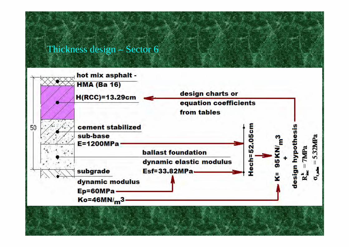
Thickness design – Sector 6
Thickness design according to TRRL Research Report 87

•Design curves (29 unreinforced and 42 reinforced forms of construction) and equations, function of traffic (equivalent standard 80 kN axles), concrete strength and foundation support, derived by multiple regression analysis;
•For our design, the traffic of 1.5 millions 115 kN standard axles was converted to 80kN standard axles, using AASHTO Guide equivalencecoefficients, resulting 19.35 millions standard 80 kN axles (msa).
•According to Table 2, for 15 cm lean concrete upper layer (stabilized sub-base) and 15 cm capping layer (ballast foundation), with subgrade of CBR=5, the equivalent foundation modulus was established as approximately 350 MPa (358MPa);

ln(L)=5.094 ln(H) + 3.466 ln(S) + 0.4836ln(M) + 0.08718ln(F) - 40.78
where:
L - estimate of the cumulative traffic, in msa;H - thickness, in mm, of the plain concrete slab;S - 28-day mean compression strength,in MPa, of cubes made from the pavement concrete;M - the equivalent modulus, in MPa, of an uniform foundation, giving the same support as the actual foundation;F - the percentage of failed bays (10%...50%).
Design equation

Results of thickness design study for PCC, SFRC and RCC slabs
Thickness design according to Mechanistic –Empirical Pavement Design Guide:M-E PDG

Thickness design according to Mechanistic –Empirical Pavement Design Guide:M-E PDG
Key features of the mechanistic-based design process developed under NCHRP 1-37A, include inputs (site factors, a trial design, and design criteria), input processing over the design period, a finite element structural response model, the incremental damage summation on an hourly and monthly basis over time, and the prediction of JPCP performance with several calibrated models.
Professor RADU ANDREI
Thickness design according to Mechanistic –Empirical Pavement Design Guide: M-E PDG
The output results over the entire design period are as follows:
• Joint faulting:
• Joint spalling:
• Transverse cracking (top down and bottom up):.
• International Roughness Index (IRI) of the JPCP: An empirical model that includes faulting, spalling, cracking, and site factors as a function of time.
Professor RADU ANDREI

Predicted Faulting
0.00
0.02
0.04
0.06
0.08
0.10
0.12
0.14
0 2 4 6 8 10 12 14 16 18 20 22 24 26 28 30 32
Pavement age, years
Faul
ting,
in Faulting plain concreteFaulting SFRCFaulting Limit
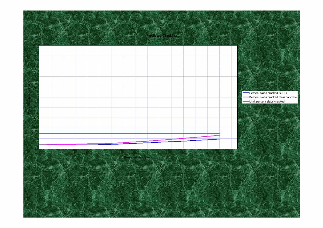
Predicted Cracking
0
10
20
30
40
50
60
70
80
90
100
0 2 4 6 8 10 12 14 16 18 20 22 24 26 28 30 32
Pavement age, years
Perc
ent s
labs
cra
cked
, %
Percent slabs cracked SFRCPercent slabs cracked plain concreteLimit percent slabs cracked

Predicted IRI
0
50
100
150
200
250
300
350
400
450
500
0 2 4 6 8 10 12 14 16 18 20 22 24 26 28 30 32
Pavement age, years
IRI,
in/m
ile IRI plain concreteIRI LimitIRI SFRC

Thickness Design Results
14.89cm-20.5cm22.02cmTRRL
13.29cm-16.19cm20.97cmNP 081-2002
RCCSFRCCSFRCUPC
Sector 6Sector 5Sectors 2-4
Sector 1

Conclusions and Recommendations
1. This comparative design study has been undertaken by using Romanian and UK and M-E PDG methods of design and will be extended with the PCA- KENSLAB method .
2. The first two methods of design used in the investigation produced thickness of SFRC/SFRCC slab lower than that obtained for unreinforced concrete slab, and significantly reduced in case of the Romanian method. The reason for this may consist in the difference in philosophy of design and criteria (flexural concrete strength/RO vs. compressive strength/UK). These thicknesses have been validated also by the M-E PDG procedure .
FAILURE CRITERIA FOR RIGID PAVEMENTS
FAILURE CRITERIA FOR RIGID PAVEMENTS*Theoretical criteria * Empirical/practical criteria

FAILURE CRITERIA FOR RIGID PAVEMENTSTheoretical criteria : The theoretical criterium is represented by the fatiguelaw adopted for the cement concrete1.Portland Cement Association (USA)2.Darter(USA)3.Huang: Pavement Analysis and design/1993 (USA)4.NP 081-2002(RO)

FAILURE CRITERIA FOR RIGID PAVEMENTSEmpirical/practical criteria
1.TRRL Research Report 87 : Mayhew H.C. , Harding H.M., Thickness design of concrete roads2. AND 547-98: Recommendation for assessment of technical condition of modern roads ( in Romanian)

FAILURE CRITERIA FOR RIGID PAVEMENTSTRRL Research Report 87/ Empirical/practical criteria :•a crack of width equal to or greater than 0.5 mmcrossing the bay longitudinally or transversally;•a longitudinal and transverse crack intersecting, both starting from an edge and greater than 0.5 mm wide, and each longer than 200 mm;•corner cracking wider than 1.3 mm and more than 200 mm radius;•a replaced or structurally repaired bay.

FAILURE CRITERIA FOR RIGID PAVEMENTSEmpirical/practical criteria : AND 547-98: Recommendation for
assessment of technical condition of modern roads a. Distress of slabs• breaking of the slab• active or passive cracks •Potholes of 5 …50cm2/ depth more than 3 cmb. Distress of structure • pumping• faulting /settlement of slabs more than 5 cm under the 3m straight edge• alligator cracks in small ( 10…30cm0 or big (50…100cm) plates•Complete breaking of slabs