Embed Size (px)
Citation preview

MIL-HDBK-1388
UNITED STATES OF AMERIC
A
LOGISTIC SUPPORT ANALYSIS
NON-MEASUREMENT SENSITIVE
DRAFT
MILITARY HANDBOOK
NOTE: This draft dated 1 Mar 94, prepared by the U.S. Army Materiel Command, LogisticsSupport Activity has not been approved is subject to modification.
DO NOT USE PRIOR TO APPROVAL
DRAFT

MIL-HDBK-1388
i
FOREWORD
1. This military handbook is approved for use by all departments andagencies of the Department of Defense (DOD).
2. Beneficial comments (recommendations, additions, deletions) and anypertinent data which may be of use in improving this document should beaddressed to: Director, USAMC Logistic Support Activity, ATTN: AMXLS-ALD,Huntsville, AL 35898-7466 by using the self-addressed Standardization DocumentImprovement Proposal (DD Form 1426) appearing at the end of this document orby letter.
3. This handbook is directed toward improving the understanding of theLogistic Support Analysis (LSA) process as it pertains to MIL-STD-1388-1,Logistic Support Analysis and MIL-STD-1388-2, DOD Requirements for a LogisticSupport Analysis Record and their associated interfacing standards anddocuments. This handbook is to be used in concurrent with MIL-STD-1388-1 andMIL-STD-1388-2. The tailoring of LSA data and LSA Record (LSAR) data shouldbe done in accordance with the tailoring guidance provided by each of therespective documents.
CONTENTS
MIL-HDBK-1388
ii
Paragraph Page1.0 Purpose..............................................................1 1.1 Application of Handbook............................................1 1.1.1 Content of Appendices............................................1 1.1.2 Tailoring........................................................1 1.1.3 LSA Process......................................................12.0 Referenced Documents.................................................13.0 Definitions..........................................................3
CHAPTER 1 LSA AND THE ACQUISITION PROCESS................................1-110.0 LSA and the Acquisition Process....................................1-1 10.1 Major Criteria...................................................1-1 10.1.1 Manpower and Personnel Constraint.............................1-1 10.1.2 System Readiness..............................................1-1 10.1.3 Cost..........................................................1-1 10.2 Acquisition Process..............................................1-1 10.2.1 Concept Exploration/Definition (CED) Phase....................1-1 10.2.2 Demonstration and Validation (D&V) Phase......................1-1 10.2.3 Engineering and Manufacturing (EMD) Phase.....................1-3 10.2.4 Production and Deployment (P&D) Phase.........................1-3 10.2.5 Operations and Support Phase..................................1-3 10.3 LSA Process......................................................1-3 10.3.1 Analysis of Supportability....................................1-3 10.3.1.1 System Level Analysis.....................................1-3 10.3.1.2 System Level Tradeoffs....................................1-3 10.3.1.3 Optimization..............................................1-3 10.3.2 Assessment and Verification...................................1-4 10.4 Interfaces........................................................1-4 10.4.1 Comparative Analysis (Task 203)...............................1-4 10.4.2 Functional Requirements Identification (Task 301).............1-4 10.4.3 Tradeoff Analysis (Task 303)..................................1-4 10.4.4 Task Analysis (Task 401)......................................1-4 10.4.5 Inputs and Outputs for System Level LSA (Subtask 303.2.3).....1-7 10.4.6 Refinement and Extension of System Level LSA..................1-7 10.4.7 Task Analysis Interfaces......................................1-7 10.4.8 Resource requirements Identification..........................1-7 10.5 Strategy in Developing Analysis Requirements......................1-7 10.5.1 General.......................................................1-7 10.5.2 Task Selection and Focusing...................................1-7 10.5.2.1 General...................................................1-7 10.5.2.2 Focusing..................................................1-8 10.5.3 Factors Impacting Strategy....................................1-8 10.5.3.1 Type of Program/Change....................................1-8 10.5.3.2 Amount of Design Freedom..................................1-9 10.5.3.3 Time and Resources Available..............................1-9 10.5.3.4 Work Already Done........................................1-10 10.5.3.5 Past Experience and Historical Data......................1-10 10.5.3.6 Procurement Consideration................................1-10 10.6 LSA Task Application.............................................1-21 10.6.1 LSA Definition...............................................1-21 10.6.1.1 LSA Process..............................................1-21 10.6.2 Hardware Levels to Which the LSA Process is Applied..........1-22 10.6.3 LSA Tasks....................................................1-22

MIL-HDBK-1388
iii
10.6.3.1 Task 101 - Development of an Early Logistic Support Analysis Strategy........................................1-25 10.6.3.2 Task 102 - Logistic Support Analysis Plan................1-26 10.6.3.3 Task 103 - Program and Design Reviews....................1-26 10.6.3.4 Task 201 - Use Study.....................................1-27 10.6.3.5 Task 202 - Mission Hardware, Software and Support System Standardization...................................1-28 10.6.3.6 Task 203 - Comparative Analysis..........................1-28 10.6.3.7 Task 204 - Technological Opportunities...................1-29 10.6.3.8 Task 205 - Supportability and Supportability Related Design Factors...........................................1-29 10.6.3.9 Task 301 - Functional Requirements Identification........1-30 10.6.3.10 Task 302 - Support System Alternatives..................1-31 10.6.3.11 Task 303 - Evaluation of Alternatives and Tradeoff Analysis................................................1-31 10.6.3.12 Task 401 - Task Analysis................................1-32 10.6.3.13 Task 402 - Early Fielding Analysis......................1-33 10.6.3.14 Task 403 - Post Production Support Analysis.............1-34 10.6.3.15 Task 501 - Supportability Test, Evaluation, and Verification............................................1-34 10.6.4 LSA Tailoring Process.......................................1-35 10.6.5 LSA and the Managerial Functions............................1-35 10.6.5.1 Planning and Controlling.................................1-35 10.6.5.2 Coordination.............................................1-35 10.7 ILS, LSA, LSAR, and System Engineering...........................1-36 10.8 LSA Documentation...............................................1-40 10.8.1 LSA Information..............................................1-40 10.8.2 Updates......................................................1-40 10.8.3 LSAR.........................................................1-40 10.8.3.1 LSAR Documentation Process...............................1-40 10.9 Logistic Support Analysis Record.................................1-41 10.9.1 Purpose......................................................1-41 10.9.2 LSAR Data Process............................................1-41 10.9.3 Manual Verse Automated LSAR..................................1-41 10.9.4 LSAR Data Tailoring Process..................................1-41 10.10 LSAR Data Tables and Reports....................................1-47 10.10.1 General.....................................................1-47 10.10.2 Cross Functional Requirement................................1-47 10.10.3 Operation and Maintenance (O&M) Requirements................1-47 10.10.4 Item Reliability, Availability, and Maintainability Requirements; Failure Mode Effects and Criticality Analysis; and, MaintainabilityAnalysis...............................1-48 10.10.5 Task Analysis, Personnel and Support Requirements...........1-49 10.10.6 Support Equipment and Training Material Requirements........1-50 10.10.7 Unit Under Test Requirements and Description................1-51 10.10.8 Facilities Consideration....................................1-52 10.10.9 Personnel Skill Considerations..............................1-53

MIL-HDBK-1388
iv
10.10.10 Packaging and Provisioning Requirement.....................1-53 10.10.11 Transportability Engineering Analysis......................1-54
CHAPTER 2 CONTRACTING....................................................2-120.0 Contracting for LSA................................................2-1 20.1 Application in Procurement.......................................2-1 20.1.1 Pre-RFP and Bidders Briefings.................................2-1 20.1.2 Preparing LSA RFP Requirements................................2-1 20.1.2.1 Broad Versus Specifics....................................2-1 20.1.2.2 Interfaces................................................2-1 20.1.2.3 Interweave Supportability Requirements and Constraints....2-1 20.1.2.4 Relative Importance of Requirements.......................2-2 20.1.2.5 Support Related Design Drivers............................2-2 20.1.2.6 Alternate Support Concepts................................2-2 20.1.2.7 Evaluation Methods and Models.............................2-2 20.1.2.8 Provisioning Procedures...................................2-2 20.1.2.9 Spares Acquisition Integrated with Production (SAIP)......2-5 20.2 Task Documentation................................................2-5 20.3 Contracting for LSAR............................................2-15 20.3.1 Objective....................................................2-15 20.3.2 Factors to Consider..........................................2-15 20.3.2.1 Type of Acquisition......................................2-15 20.3.2.2 Phase of Development.....................................2-16 20.3.2.3 LSAR Level of Effort.....................................2-16 20.3.2.4 Previous LSAR Effort.....................................2-16 20.3.2.5 Degree of Program Control................................2-16 20.4 Determine Logistics Products....................................2-17 20.4.1 Logistic Products Figures....................................2-17 20.4.2 Reliability and Maintainability..............................2-17 20.4.3 Maintenance Planning.........................................2-18 20.4.4 Technical Data and Manuals...................................2-19 20.4.5 Support and Test Equipment...................................2-19 20.4.6 Supply Support...............................................2-20 20.4.7 Supply Support (continued)...................................2-20 20.4.8 Manpower, Personnel, and Training............................2-21 20.4.9 Facilities...................................................2-22 20.4.10 Packaging, Handling, Storage, and Transportability..........2-22 20.5 LSAR Analysis Reports...........................................2-23 20.5.1 LSA-001, Annual Man-Hours by Skill Specialty Code and Level of Maintenance.........................................2-23 20.5.2 LSA-003, Maintenance Summary.................................2-23 20.5.3 LSA-005, Support Item Utilization Summary....................2-23 20.5.4 LSA-006, Critical Maintenance Item Summary...................2-23 20.5.5 LSA-007, Support Equipment Requirements......................2-23 20.5.6 LSA-008, Support Items Validation Summary...................2-23 20.5.7 LSA-009, Support Items List..................................2-24 20.5.8 LSA-010, Parts Standardization Summary.......................2-24 20.5.9 LSA-011, Requirements for Special Training...................2-24 20.5.10 LSA-013, Support Equipment Grouping Number Utilization Summary.....................................................2-24
MIL-HDBK-1388
v
20.5.11 LSA-027, Failure/Maintenance Rate Summary...................2-24 20.5.12 LSA-037, Spares and Support Equipment Identification List...2-24 20.5.13 LSA-039, Critical and Strategic Item Summary................2-24 20.5.14 LSA-046, Nuclear Hardness Critical Item Summary.............2-24 20.5.15 LSA-078, Hazardous Materials Summary........................2-24 20.5.16 LSA-126, Hardware Generation Breakdown Tree.................2-25 20.5.17 LSA-152, PLISN Assignment/Reassignment......................2-25 20.5.18 LSA-154, Provisioning Parts Breakout Summary................2-25 20.6 AD-HOC Queries..................................................2-25 20.6.1 Example AD-HOC Query.........................................2-25 20.7 DD Form 1949-3, LSAR Data Requirements Form.....................2-26 20.7.1 Data Element Selection.......................................2-26 20.7.2 Selection of 1949-3 Data Elements............................2-26 20.7.2.1 DD Form 1949-3 Sections and Parts........................2-26 20.7.2.2 DD Form 1949-3, General Information......................2-26 20.7.2.3 Section 1 of DD Form 1949-3, Government Furnished Data...2-26 20.7.2.4 Peculiarities of 1949-3..................................2-27 20.7.2.4.1 Data Element Selection...............................2-27 20.7.2.5 Data Element Selection DD Form 1949-3 Example............2-27 20.8 Delivery of LSAR Data...........................................2-35 20.8.1 Hard Copy LSAR Reports.......................................2-35 20.8.2 Master Table Delivery........................................2-35 20.8.3 On-Line Access...............................................2-36 20.8.4 Delivery Combination.........................................2-36 20.9 Example Statement of Work.......................................2-37 20.10 Conversion From 1388-2A to 1388-2B..............................2-39 20.10.1 Additional Data.............................................2-40
CHAPTER 3 LSAR REPORT SPECIFICATIONS.....................................3-130.0 LSAR Reports.......................................................3-1 30.1 Common Selection Criteria........................................3-1 30.1.1 EIAC..........................................................3-1 30.1.2 LCN...........................................................3-1 30.1.3 ALC...........................................................3-2 30.1.4 UOC...........................................................3-2 30.1.5 Service Designator............................................3-2 30.1.6 O/M Levels....................................................3-2 30.1.7 ICC’s.........................................................3-2 30.2 Subordinate LCN/ALC...............................................3-2 30.3 Task Referencing or Subtask Referencing..........................3-3 30.3.1 Report Usage of Referenced Tasks/Subtasks......................3-3 30.4 LSA-001, Annual Man-Hours by Skill Specialty Code and Level of Maintenance Report Specifications........................3-4 30.5 LSA-003, Maintenance Summary Report Specifications .............3-7 30.6 LSA-004, Maintenance Allocation Chart Report Specification.......3-11 30.7 LSA-005, Support Item Utilization Summary Report Specification...3-20 30.8 LSA-006, Critical Maintenance Item Summary Report Specification..3-23 30.9 LSA-007, Support Equipment Requirements by SSC and Maintenance Level Report Specification.......................................3-26 30.10 LSA-008, Support Items Validation Summary Report Specification..3-28 30.11 LSA-009, Support Items List Report Specification................3-31
MIL-HDBK-1388
vi
30.12 LSA-010, Parts Standardization Summary Report Specification.....3-34 30.13 LSA-011, Requirements for Special Training Report Specification.3-36 30.14 LSA-012, Facility Requirements Report Specification.............3-38 30.15 LSA-013, Support Equipment Grouping Number Utilization Summary Report Specification....................................3-43 30.16 LSA-014, Training Task List Report Specification................3-45 30.17 LSA-016, Preliminary Maintenance Allocation Chart Report Specification...................................................3-48 30.18 LSA-018, Task Inventory Summary Report Specification............3-54 30.19 LSA-019, Task Analysis Summary Report Specification.............3-56 30.20 LSA-023, Maintenance Plan Summary Report Specification..........3-60 30.21 LSA-024, Maintenance Plan Report Specification..................3-69 30.22 LSA-025, Packaging Requirements Data Report Specification.......3-79 30.23 LSA-026, Packaging Developmental Data Report Specification......3-82 30.24 LSA-027, Failure/Maintenance Rate Summary Report Specification..3-84 30.25 LSA-030, Indentured Parts List Report Specification.............3-91 30.26 LSA-032, Defense Logistics Service Center (DLSC) Submittals Provisioning Screening Report Specification....................3-101 30.27 LSA-033, Preventive Maintenance Checks and Services Report Specification..................................................3-105 30.28 LSA-036, Provisioning Requirements Report Specification........3-108 30.29 LSA-037, Spares and Support Equipment Identification List Report Specification..................................................3-118 30.30 LSA-039, Critical and Strategic Item Summary Report Specification .................................................3-121 30.31 LSA-040, Authorization List Items Summary Report Specification.3-124 30.32 LSA-046, Nuclear Hardness Critical Item Summary Report Specification .................................................3-129 30.33 LSA-050, Reliability Centered Maintenance Summary Report Specification..................................................3-131 30.34 LSA-056, Failure Modes, Effects, and Criticality Analysis (FMECA) Report Specification...................................3-139 30.35 LSA-058, Reliability and Maintainability Analysis Report Specification..................................................3-148 30.36 LSA-065, Manpower Requirements Criteria (MARC) Report Specification..................................................3-151 30.37 LSA-070, Support Equipment Recommendation Data (SERD) Report Specification..................................................3-154 30.38 LSA-071, Support Equipment Candidate List Report Specification.3-173 30.39 LSA-072, Test, Measurement and Diagnostic Equipment Requirements Summary Report Specification......................3-
MIL-HDBK-1388
vii
176 30.40 LSA-074, Support Equipment Tool List Report Specification......3-181 30.41 LSA-075, Consolidated Manpower, Personnel and Training Report Specification..................................................3-185 30.42 LSA-076, Calibration and Measurement Requirement Summary Report Specification..................................................3-189 30.43 LSA-077, Depot Maintenance Interservice Data Summary Report Specification..................................................3-193 30.44 LSA-078, Hazardous Materials Summary Report Specification......3-199 30.45 LSA-080, Bill of Materials Report Specification................3-201 30.46 LSA-085, Transportability Summary Report Specification.........3-205 30.47 LSA-126, Hardware Generation Breakdown Tree Report Specification .................................................3-211 30.48 LSA-151, Provisioning Parts List Index Report Specification....3-213 30.49 LSA-152, PLISN Assignment/Reassignment Report Specification....3-216 30.50 LSA-154, Provisioning Parts Breakout Summary Report Specification..................................................3-220 30.51 LSA-155, Recommended Spare Parts List for Spare Acquisition Integrated with Production (SAIP) Report Specification.........3-223
CHAPTER 4 LSAR SOFTWARE VALIDATION.......................................4-140.0 Objective..........................................................4-1 40.1 General..........................................................4-1 40.2 Purpose..........................................................4-1 40.3 Differences in Validation Requirements with the Revised Standard.4-1 40.3.1 Type 1........................................................4-1
40.3.2 Type 2........................................................4-1 40.3.3 Type 3........................................................4-1 40.4 Differences in LSAR Software System Design Criteria 2A versus 2B.4-1 40.4.1 Master Table(s) Acceptance....................................4-2 40.4.2 Master Table(s) Delivery......................................4-2 40.4.3 LSAR Reports..................................................4-2 40.4.4 Appendix A and E..............................................4-2 40.4.5 Change Only Data..............................................4-3 40.4.6 Comment Capabilities..........................................4-3 40.5 General Validation Procedures....................................4-3 40.5.1 Step 1........................................................4-3 40.5.2 Step 2........................................................4-3 40.5.3 Step 3........................................................4-3 40.5.4 Step 4........................................................4-3 40.5.5 Step 5........................................................4-4 40.5.6 Step 6........................................................4-4 40.6 Validation Completion............................................4-4 40.7 Validation Renewal Procedures....................................4-4 40.7.1 Renewal Request...............................................4-4

MIL-HDBK-1388
viii
40.7.2 Renewal Issuance..............................................4-4 40.8 LSAR ADP System Revalidation.....................................4-4 40.9 Disapproval of Validation Request................................4-5 40.10 Revocation of Validation.........................................4-5 40.11 Considerations for Software Evaluation...........................4-5 40.12 LSAR Independently Developed ADP Pamphlet........................4-5
CHAPTER 5 GUIDANCE FOR ASSIGNMENT OF LCN, ALC, LCN TYPE AND UOC..........5-150.0 Purpose.............................................................5-1 50.1 Traditional LCN Assignment.......................................5-1 50.2 Functional and Physical LCN Assignments..........................5-1 50.2.1 LCN Type......................................................5-3 50.3 LCN Assignment...................................................5-3 50.3.1 Classical LCN Assignment......................................5-5 50.3.2 Modified Classical Assignment Method..........................5-5 50.3.3 Sequential Assignment Method..................................5-5 50.4 Alternate LCN Code (ALC).........................................5-5 50.4.1 ALC Usage for a Single Configuration/Model....................5-9 50.4.2 ALC Usage for LSAR Reports....................................5-9 50.4.3 Lower-tiered LCN/ALC Selection...............................5-11 50.5 Usable On Code..................................................5-11 50.5.1 ALC and UOC Relationship.....................................5-11 50.5.2 UOC and ALC Usage for LSAR Reports...........................5-12 50.6 Summary.........................................................5-12
CHAPTER 6 ACTIVITY AND DATA MODELING.....................................6-160.0 Activity and Data Modeling.........................................6-1 60.1 Activity Modeling................................................6-1 60.2 Data Modeling....................................................6-1 60.3 LSAR Data Model..................................................6-1 60.3.1 Normalization.................................................6-2 60.4 Implementation of the LSAR Data Model for MIL-STD-1388-2B.......6-13
APPENDIX A ACRONYM LISTING...............................................A-1
APPENDIX B MIL-STD-1388-2B DATA TABLES AND REPORTS.......................B-11.0 Data Tables and Report...............................................B-1 1.1 Purpose............................................................B-1 1.2 Report Comparison..................................................B-1 1.3 New 1388-2b Reports................................................B-2 1.4 LSAR Data Tables....................................................B-2 1.5 Data Table to Report Usage.........................................B-7
APPENDIX C PROVISIONING..................................................C-11.0 Introduction.........................................................C-1 1.1 Purpose............................................................C-1 1.2 Product Reports and Their Interrelationship........................C-12.0 Coding Requirements and Report Selection Logic Exception for Provisioning Reports.................................................C-3 2.1 Assignment of the LCN..............................................C-3 2.2 UOC Assignment.....................................................C-3
MIL-HDBK-1388
ix
2.3 Alternate LCN Assignment...........................................C-3 2.4 FGC (WUC/TM FGC) Versus LCN Assignment.............................C-4 2.5 TM Code............................................................C-7 2.6 LCN-IC and IC.....................................................C-12 2.7 Provisioning Contract Control Number (PCCN) Relationships.........C-13 2.8 Suppression Indicator Code (SIC)..................................C-143.0 Maintenance Allocation Chart (MAC)..................................C-16 3.1 Purpose of the MAC................................................C-16 3.2 MAC Man-Hour Computations.........................................C-17 3.3 Relationship of the MAC and Tool and Test Equipment Requirements Sections..........................................................C-18 3.4 MAC Source Data...................................................C-184.0 Provisioning Requirements...........................................C-20 4.1 Preparation of the PMF............................................C-20 4.2 Utilization of the Automatic PLISN Assignment Routine.............C-21 4.3 Defense Logistics Information System (DLIS) Submittals............C-23 4.4 Provisioning Parts List Index.....................................C-25 4.5 LSA-036 System....................................................C-26 4.5.1 Report Sequence...............................................C-26 4.5.2 Report Format.................................................C-26 4.5.3 Report Options................................................C-26 4.5.4 Control Data..................................................C-31 4.5.5 Provisioning Baseline File (PBF)..............................C-31 4.5.6 QPEI Calculation..............................................C-32 4.5.6.1 Option 1 Quantity Per End Item............................C-32 4.5.6.2 Option 2 Quantity Per End Item............................C-36 4.5.6.3 Option 3 Quantity Per End Item............................C-36 4.5.7 Same as PLISN.................................................C-38 4.5.8 Update Transactions...........................................C-39 4.5.8.1 Update Processing.........................................C-40 4.5.9 The LSA-036 Report Header.....................................C-43 4.5.10 The LSA-036 Part II Error Report.............................C-46 4.5.11 LSA-036 Part III Options.....................................C-46 4.5.11.1 Army LSA-036 System Edits................................C-46 4.5.11.2 Air Force "L" Card Merge Routine.........................C-47 4.6 Provisioning Utilities............................................C-47 4.6.1 Sesame Extract Program........................................C-47 4.6.2 Government/Contractor PBF Comparison..........................C-47 4.6.3 LSA-036 to PMF Update Transactions............................C-47 4.6.4 QPEI Calculation by PCCN and UOC..............................C-475.0 Repair Parts and Special Tool List (RPSTL)..........................C-48 5.1 RPSTL Content.....................................................C-48 5.2 Report Selection..................................................C-48 5.3 Documentation of KITS for RPSTL...................................C-48 5.4 Data Content......................................................C-49 5.5 Draft/Proof RPSTL Review..........................................C-50

MIL-HDBK-1388
x
MIL-HDBK-1388
1.0 Purpose. This handbook provides an easy to understand ready referencedocument for the entire LSA process as it is generally applied to a DODacquisition program.
1.1 Application of handbook. This handbook applies to all system/equipmentacquisition programs, major modification programs, and applicable research anddevelopment projects through all phases of the system/equipment life cycle.This handbook is for use by both contractor and government activities. Asused in this handbook, the requiring authority is generally a governmentactivity but may be a contractor when LSA documentation requirements arelevied on subcontractors. The performing activity may be either a contractoror government activity. The use of the term, contract, in this standardincludes any document of agreement between organizations to include between agovernment activity and another government activity, between a governmentactivity and a contractor, or between a contractor and another contractor.
1.1.1 Content of appendices. There are three appendices in this handbook.Appendix A contains a list of acronyms, appendix B is reference material onMIL-STD-1388-2B data tables and reports, and appendix c contains a proceduralsupplement to MIL-STD-1388-2B. This supplement will help in thedocumentation and report selection of provisioning related reports.

MIL-HDBK-1388
2
1.1.2 Tailoring. This handbook cannot be specified directly in a contract.MIL-STD-1388-1 and MIL-STD-1388-2 should be the standards specified in acontract. The requiring authority (RA) and the material developer (MD) willuse MIL-STD-1388-1 in the selection of tasks for inclusion in the contractstatement of work (SOW) and shall establish the LSA documentation requirementsbased upon the elements identified in those tasks.
1.1.3 LSA process. MIL-STD-1388-1 and MIL-STD-1388-2, implements the LSAguidelines and requirements established by DOD Instruction 5000.2, DefenseAcquisition Management Policies and Procedures, and DOD Directive 5000.1,Defense Acquisition. This handbook discusses the LSA and LSAR process;contracting for LSA and LSAR; LSAR report selection option and reportspecifications; LSAR software validation process; LSA Control Number (LCN),Alternate LCN Code (ALC), and Usable On Code (UOC) application in a functionalverse physical environment; and an explanation of the data modeling processwhich was used to develop the relational LSAR data base.
2. REFERENCED DOCUMENTS.
2.1 General. Completion of the LSA process requires use of many relateddocuments from which the appropriate data can be obtained. The specific useof each document is identified in the appropriate chapter or appendix of thishandbook. Unless otherwise specified, the following standards and handbooksof the issue listed in that issue of the Department of Defense Index ofSpecifications and Standards (DODISS), specified in the solicitation form, apart of this standard to the extent specified, herein.
Military Standards.
MIL-STD-335 Manuals Technical Repair Parts and Special Tools List
MIL-STD-470 Maintainability Program for Systems and Equipment
MIL-STD-471 Maintainability Verification/Demonstration/Evaluation
MIL-STD-680 Contractor Standardization Program Requirements
MIL-STD-756 Reliability Modeling and Prediction
MIL-STD-785 Reliability Program for Systems and Equipment Development and Production
MIL-STD-881 Work Breakdown Structures for Defense Materiel Items
MIL-STD-882 System Safety Program Requirements
MIL-STD-965 Parts Control Program
MIL-STD-1366 Transportability Criteria

MIL-HDBK-1388
3
MIL-STD-1367 Packaging, Handling, Storage, and Transportability Program Requirements for Systems and Equipment
MIL-STD-1379 Military Training Programs
MIL-STD-1388-1 Logistic Support Analysis
MIL-STD-1388-2 DOD Requirements for a Logistic Support Analysis Record
MIL-STD-1390 Level of Repair
MIL-STD-1478 Human Performance Analysis
MIL-STD-1629 Procedures for Performing a Failure Mode, Effect, and Criticality Analysis
MIL-STD-1839 Calibration and Measurement Requirements
MIL-STD-1843 Reliability Centered Maintenance for Aircraft Engines and Equipment
MIL-STD-2073-1 DOD Materiel Procedures for Development and Application of Packaging Requirements
MIL-STD-2073-2 Packaging Requirement Codes
MIL-STD-2097 Requirements for Acquisition of End Items of Support Equipment, Associated Integrated Logistics Support, and Related Technical Data for Air Systems
MIL-STD-2173 Reliability Centered Maintenance For Naval Aircraft Weapon Systems and Support Equipment
Military Handbooks.
MIL-HDBK-217 Reliability Prediction of Electronic Equipment
MIL-H-46855 Human Engineering Requirements for Military Systems, Equipments, and Facilities
Military Specifications.
MIL-T-31000 Technical Data Packages, General Specifications for
MIL-M-38807 Manuals, Techincal: Illistrated Parts Breakdown, Preparation of
MIL-M-49502 Manuals, Technical: Repair Parts and Special Tool List
MIL-M-63036 Manuals, Technical: Operator’s, Preparation of (Army)
MIL-M-63038B Manuals, Technical: Organizational or Aviation Unit Direct Support, or Aviation Intermediate, and General Support

MIL-HDBK-1388
4
Maintenance (Army)
Federal Manuals and Catalogs.
H6-1 Federal Item Name Directory for Supply Cataloging
Other Documents.
AMCP 750-2 Guide to Reliability Centered Maintenance
DARCOM 750-16 DARCOM Guide to Logistic Support Analysis DARS NO.6 Defense Acquisition Regulation Supplement NO. 6
DOD 4100.38-M DOD Provisioning and Other Preprocurement Screening Manual
DODD 5000.1 Defense Acquisition
DODI 5000.2 Defense Acquisition Management Policies and Procedures
MTMC PAM 70-1 Transportability for Better Strategic Mobility
MRSAP 700-11 Cost Estimating Methodology for Logistic Support Analysis (CELSA) Guide
(Non-Government standards and other publications are normally available fromthe organizations that prepare or distribute the documents. These documentsalso may be available in or through libraries or other informationalservices.)
3. DEFINITIONS.
3.1 Assembly. A number of parts or subassemblies, or any combinationthereof, joined together to perform a specific function and capable ofdisassembly (e.g., power shovel-front, fan assembly, audio frequencyamplifier). NOTE: The distinction between an assembly and subassembly isdetermined by the individual application. An assembly, in one instance, maybe a subassembly in another where it forms a portion of an assembly.
3.2 Component. An assembly or any combination of parts, subassemblies, andassemblies mounted together normally capable of independent operation in avariety of situations.
3.3 Design Change. An approved engineering change incorporated into the enditem which modifies, adds to, deletes, or supersedes parts in the end item.
3.4 End Item. A final combination of end products, component parts/materialswhich is ready for its intended use, e.g., ship, tank, mobile machine shop,aircraft, receiver, rifle, or recorder.
3.5 LSA. The selective application of scientific and engineering effortsundertaken during the acquisition process, as part of the system engineeringand design process, to assist in complying with supportability and other ILS
MIL-HDBK-1388
5
objectives.
3.6 LSAR. That portion of LSA documentation consisting of detailed datapertaining to the identification of logistic support resources requirements ofa system/end item/equipment.
3.7 LSA Candidate. A component, subassembly, assembly, software, or enditem/article on which maintenance action is considered feasible as a result ofa preliminary or detailed tradeoff analysis.
3.8 LSA Documentation. All data resulting from performance of LSA tasks,conducted under MIL-STD-1388-1, to include LSAR, pertaining to an acquisitionprogram.
3.9 Manufacturers Part Number. See reference number.
3.10 Material Developer. The organization, government or industry, that isoverseeing the development of a piece of hardware/software.
3.11 Part. One, two or more pieces, joined together which are not normallysubject to disassembly without destruction or impairment of designed use.
3.12 Part Number. See reference number.
3.13 Performing Activity. The organization, government or industry, that isbuilding/designing a piece of hardware/software.
3.14 Reference Number. Any number, other than a government activity stocknumber, used to identify an item of production, or used by itself or inconjunction with other reference numbers to identify an item of supply.Reference numbers include: manufacturer’s part, drawing, model, type, orsource controlling numbers; manufacturer’s trade name; specification orstandard numbers; and, specification or standard part, drawing, or typenumbers.
3.15 Repair Part. Material capable of separate supply and replacement whichis required for the maintenance, overhaul, or repair of a system, equipment orend item. This definition does not include Support Equipment, but doesinclude repair parts for support equipment.
3.16 Requiring Authority. The organization, government, that has arequirement for a piece of hardware/software.
3.17 Spares. Articles identical to or interchangeable with the end articleson contract which are procured over and above the quantity needed for initialinstallation for support of a system.
3.18 Subassembly. Two or more parts which form a portion of an assembly or acomponent replaceable as a whole, but having a part or parts which areindividually replaceable (e.g., gun mount stand, window recoil mechanism,floating piston, telephone dial, mounting board with mounted parts, powershovel dipper stick).

MIL-HDBK-1388
6
3.19 Support Equipment. "Support Equipment" is that equipment required tomake an item, system, or facility operational in its intended environment.This includes all equipment required to maintain and operate the item, system,or facility including aerospace ground equipment and ground equipment.
3.20 Support Items. Items subordinate to or associated with an end item,i.e., spares, repair parts, and support equipment.
Chapter 1MIL-HDBK-1388
1-1
10. LOGISTIC SUPPORT ANALYSIS AND THE ACQUISITION PROCESS.
10.1 Major Criteria. DOD Directives 5000.l and 5000.2 establish IntegratedLogistic Support (ILS) and acquisition policies. Prime factors governingsystem acquisition programs are cost, schedule, and performance withsupportability being a subset of performance. The LSA provides directsupportability and cost factor input for new systems and provides major inputto system decisions. Specific criteria and emphasis varies from system tosystem, but three prime LSA outputs emerge at the level affecting acquisitiondecisions. These are described below.
10.1.l Manpower and Personnel Constraints. Manpower and skill levelrequirements are treated as any major design function. Personnel parametersbegin with the initial concept. DODI 5000.2, Human System Integration in theDefense System Acquisition Process, sets system manpower estimatingrequirements. Manpower and personnel requirements are stated as numbers,skills, and skill levels during the design process and may use the manpowerand personnel policies of Services.
10.1.2 System Readiness. Design parameters and logistic support resources relate to system readiness objectives and goals. Operational availability,sortie rates (surge/sustained), and percent coverage are wartime factors whichare often used for peacetime readiness measurements. System readiness, as anintegral part of system performance, must be managed beginning with theearliest conception of new/modified system/equipment.
10.1.3 Cost. Operation and support investment along with other acquisitioncosts must be considered for any acquisition. Comparison of life cycle cost(LCC) estimates to requirements for alternatives is vital to tradeoffdecisions. Cost factors should address resource requirements to achievespecified levels of readiness for given conditions. Uncertainty of resourcessuch as manpower and energy, must be addressed to minimize cost and meetsystem readiness objectives. The objective is to optimize an acquisitionrelated to system performance, cost, and schedule goals of the system.
10.2 Acquisition Process. Figure 1.1 is an overview of the acquisitionprocess, showing life cycle phases and LSA process decision points. The LSAprocess has five phases begining with a validated identified requirement. Program initiation documents are then prepared. The Acquisition phases are:
10.2.1 Concept Exploration/Definition (CED) Phase. Alternatives to satisfythe requirement are evaluated and compared in terms of performance, readiness,supportability, schedule, and cost. System level analysis which affect designand operational concepts, readiness, logistics and operational supportcharacteristics are defined. These support the use study and ILS/LSA conceptand strategy supportability constraints, of the proposed system. The ILS/LSAproducts include cost improvement and readiness targets, support conceptalternatives, supportability related design and support system objectives.
10.2.2 Demonstration and Validation (D&V) Phase. Concepts now become hardwaredesign. Removal of technical uncertainties in the design are verified andevaluated using advance development models. The ILS/LSA products now include

Chapter 1MIL-HDBK-1388
1-2
f1.1

Chapter 1MIL-HDBK-1388
1-3
firm support concepts, supportability related design goals and thresholds,readiness, and supportability system parameter objectives.
10.2.3 Engineering and Manufacturing Development (EMD) Phase. Validateddesigns are developed as models or prototypes. Functional/environmentaltesting verifies design performance requirements. The ILS/LSA effort ismaximized to influence maintenance planning and identify detailed logisticsupport resource requirments and deficiency solutions which are validated byoperational testing. Detailed analyses identify preventive/correctivemaintenance, calibration, and servicing requirements. Firm logistic supportand maintenance plans are developed. Manufacturing procedures, and controltechniques are designed for economical mass production.
10.2.4 Production and Deployment (P&D) Phase. A model or prototype developedand optimized during EMD is produced and tested. An effective support base isestablished and new systems or equipment are readied for deployment andoperational use.
10.2.5 Operations and Support Phase. This phase begins after initialfielding and overlaps Prod/Deploy. The ILS/LSA activities include: postproduction support; correction of quality and safety problems; and newtraining programs and feedback mechanisms are devised for reduction ofreadiness and supportability problem areas. The LSAR is maintained andupdated during the life cycle of the system/equipment.
l0.3 LSA Process. LSA is an iterative, multi-disciplined, process having many interfaces. It can be divided into two general parts: (a) analysis ofsupportability, and (b) assessment and verification of supportability.
10.3.1 Analysis of Supportability. These analyses affecting design andoperational concepts begin at system level; identify gross logistic supportresource requirements of alternative concepts; and relate design, operational,and supportability characteristics to system readiness objectives and goals.
10.3.1.1 System Level Analyses. These efforts are characterized by usestudies, comparative analysis studies, support driver identification,technological opportunities, tradeoffs analysis, alternative support conceptssuch as organic versus contractor support, built-in versus external testcapability, and varying maintenance levels.
10.3.1.2 System Level Tradeoffs. Analyses of lower indenture levels andsupport system optimization set by the system level analysis begin. Thesedefine logistic support resource requirements of the system using anintegrated analysis of all operator maintainer functions and tasks. These aredone to determine task frequencies, task times, personnel and skillrequirements, and other support requirements, to include all ILS elements.
10.3.1.3 Optimization. This is achieved by allocating functions and tasks tospecific maintenance levels, doing repair versus discard and ReliabilityCentered Maintnenance (RCM) analyses, and formulating design recommendationsto optimize maintenance times and logistic support resource requirements. Data developed is used as direct input for products associated with each ILS

Chapter 1MIL-HDBK-1388
1-4
element e. g., provisioning lists, personnel and training requirements, andtechnical manuals. This assures compatibility between ILS element documentsand permits common use of data which apply to more than one logistic element.
10.3.2 Assessment and Verification. The process begins with early planningto verify support concepts and is used during the entire life cycle to demonstrate and adjust analysis results and products as required.
10.4 Interfaces. Some major LSA activities and their interfaces which playkey roles are listed below:
10.4.1 Comparative Analysis (Task 203). Interfacing activities: humanfactor, reliability, maintainability, safety, and design engineers and ILSelement managers. This task is used to: define a sound, analyticalfoundation for projecting new system design and supportability features; toidentify those which need improvements; identify those cost drivers whichsupport the readiness of the new system; and document risks involved in usingthe comparative data in subsequent analyses.
10.4.2 Functional Requirements Identification (Task 301). Interfacingactivities: design, reliability, maintainability, and human factorengineering, safety and ILS element managers.
10.4.3 Tradeoff Analysis (Task 303). Interfacing activities: design,reliability, maintainability, safety, and human factor engineering, costestimating, and ILS element managers.
10.4.4 Task Analysis (Task 40l). Interfacing activities: reliability,maintainability, human factor, and safety engineering. Performed to analyzerequired operations, maintenance, and support tasks to identify resourcesneeded for each task; highlight are new or critical tasks, including hazardousmaterials and their environmental impact; define transportabilityrequirements; identify support requirements which exceed desired goals,thresholds, or constraints; provide data supporting recommended designs whichenhance readiness and supportability; and provide source data to developrequired documents, i.e., Maintenance Allocation Charts (MAC), TechnicalManuals (TM), Provisioning documentation, etc.
Figure 1.2 shows the interfaces and information flow from supporting militarystandards. Arrows indicate that information developed using one militarystandard is referenced as input from another standard. A military standardmust specifically require information developed using another standard for arelationship to be shown.
For example: Failure Modes, Effects and Criticality Analysis (FMECA) data isdeveloped using MIL-STD-1629, but is also used for analysis purposes in MIL-STD-1388-1A and is documented in MIL-STD-1388-2B; therefore, an arrow leadsfrom MIL-STD-1629 to MIL-STD-1388-1A/2B. MIL-STD-1629 does not require datadeveloped by MIL-STD-1388-1A/2B; therefore, no arrow leads from MIL-STD-1388-1A/2B to MIL-STD-1629.
Review of LSA interfaces should be described in the LSA Plan (LSAP) (Task l02)

Chapter 1MIL-HDBK-1388
1-5
f1.2

Chapter 1MIL-HDBK-1388
1-6
f1.3

Chapter 1MIL-HDBK-1388
1-7
to assure input-output relationships, responsibilities, and timing ofactivities are properly addressed to prevent over-lap and duplication. Guidance found in subsequent paragraphs will reduce interface problems.
l0.4.5 Inputs and Outputs for System Level LSA (Subtask 303.2.3). Systemlevel LSA may involve system analysis/engineering at thehardware-operating-support level. It is a collection, synthesis, and "system"analysis of various specialized input. It impacts interface activities bydefining boundary conditions or goals of specialized engineering programs andILS element concepts and plans. Figure 1.3 shows task 303.2.3 relationships.
l0.4.6 Refinement and Extension of System Level LSA. As the process isiterated, limits, constraints, and objectives are refined and expanded basedon engineering and ILS input. A support system is established with limits andobjectives set. Follow-on tradeoffs between engineering specialties and ILSelements are made within established boundaries which include Built In Test(BIT)/Built In Test Equipment (BITE) verse external dignostics (Subtask303.2.8) and training tradeoffs (Subtask 303.2.6).
10.4.7 Task Analysis Interfaces. LSA includes all task analyses, however,specific areas (e.g., critical maintenance tasks) may be analyzed as part ofthe human engineering program. Detailed task analyses input such as taskfrequencies, repair times, safety hazards, and failure effects, are normallydeveloped by reliability, maintainability, and safety specialists.
l0.4.8 Resource Requirements Identification. LSA identifies all logisticsupport resource requirements. This is an iterative process with informationbeing passed between logistics, design and specialized engineering areas.These requirements are summarized in the LSA data base. These requirementsare used by ILS managers for development of plans and products.
10.5 Strategy in Developing Analysis Requirements.
10.5.1 General. Cost effective analysis efforts channel available resourcesto areas offering the greatest benefit to the program. Strategies rely onestablishing programs to achieve supportability and support system objectives. They must influence hardware design, support, and logistic support resourcerequirements. The requirements are translated into specific objectives earlyin the program when maximum flexibility exists. Objectives are iterated andrefined until they are firm program goals/requirements. Developing analysisstrategies is difficult due to the number of variables. Possible impact ofvariables must be addressed during the process when analysis tasks/subtasksare tailored and scheduled to meet milestones. Guidance provided will assistin the tailoring process, however, it must be adapted to specific programs.
10.5.2 Task Selection and Focusing.
10.5.2.l General. Analysis requirements selection, begining at subtasklevel, includes a wide range of considerations. Figure 1.4 depicts a generaltailoring logic tree useful when selecting tasks. Table 1 lists task/subtaskuse by development phase and engineering activity. Guidance must be adjustedfor each program since program aspects may occur different acquisition phases

Chapter 1MIL-HDBK-1388
1-8
for different programs. Initial task/subtask selection is adjusted for: (a)design freedom; (b) time phasing adjustments if program is "fast track"; (c)work already done; (d) data availability/relevancy; (e) time and resourceavailability; (f) Policy directive (DODI 5000.2) requirements; (g) desiredtasks not in the standard; and (h) procurement considerations. Most of thesefactors tend to reduce or restrict the amount of analysis activity. Additional guidance is provided later in this section.
10.5.2.2 Focusing. After initial subtask selection is completed, furtherfocus is needed to concentrate effort in high leverage areas and to specifyother requirements. Focusing considerations should include: (a) Modificationor restriction of the subtask to significant areas; (b) Specification ofsubtasks to allow assignment to the appropriate activity; (c) Specification ofmodels and associated data to be used; and (d) Specification of areas oractivity requiring requester approval. RA must be specific when defininganalysis needs for tasks and subtasks under the task input specified. Oftenl0 to 20 percent of system’s subsystems control 80 to 90 percent of the totalsupport demands. Some Task 303 evaluations and tradeoffs are very general andbenefit from greater detail to focus on key areas. Models and definitions,particularly for LCC, desired for a particular analysis should be specified,if possible, especially if there is competition. Model considerations arediscussed in greater depth under procurement considerations. The remainder ofthis section deals with specific factors considered during development of theLSA strategy.
10.5.3 Factors Impacting Strategy.
10.5.3.l Type of Program/Change. Program categories are: new programs;planed product improvement (PPI); or "off-the-shelf" programs. Manymodifications require redoing or a new approach to some of the analysis workalready done. The program type impacts objectives, subtask selection andfocusing. For PPI’s, analysis objectives may focus on support risks on thealtered part, or opportunities to improve the equipment by improvingsupportability characteristics. New or high technology efforts may increaserisk to attain supportability goals. Those risks must be reduced. Usingproven technology has less risk and may offer more opportunity to reducelogistic support burdens than a more advanced technology.
These factors greatly impact on initial objective determination. Systemversus equipment proposals impact subtask selection and focusing. Forexample, a limited, focused readiness analysis may be appropriate for anequipment contract, while alternative support concepts may be more appropriatefor equipment level contracts due to a fixed system support concept.
System readiness objectives may be to "hold the line" or they may be moreambitious. Readiness goals must be a primary management focus beginning withprogram initiation. If such goals are ambitious, one focus of the earlyanalyses should be toward readiness related system design and supportobjectives, such as reliability and turn around time.
Systems and equipments having large support personnel demands or highOperations and Support (O&S) costs obviously present greater investment

Chapter 1MIL-HDBK-1388
1-9
opportunities for improvement than those with low demands or costs and shouldreceive greater consideration in selecting preliminary analysis objectives.
10.5.3.2 Amount of Design Freedom. The amount of design freedom is relatedto program considerations such as phasing and is a key factor in subtaskelection. The objective of most front end analysis subtasks is to influenceselection of design characteristics to achieve improvements in readiness,supportability, and cost. For fixed designs, little benefit be derived fromdoing these tasks. Some of the factors listed in paragraph 10.5.3.l provideclues in this regard.
Product improvements may limit design freedom to specific subsystems unlessareas of no, or minor change are open to redesign opportunity to reducelogistic support burdens.
Fast track programs tend to move up or back various possible analysissubtasks, but fast track programs also tend to use existing technology andplan on preplanned product improvement rather than employ new technology. Thepoint of design freedom thus shifts. Design freedom may exist for the supportsystem but not the mission system. LSA effort and objectives should befocused accordingly.
The LSA objective of causing supportability requirements to be an integralpart of system/equipment requirements and design can best be achieved ifdesigners are oriented toward supportability objectives commencing with thedesign effort.
Technical information documented during the design process, must be providedto designers and logisticians to help identify interface problems betweendesign concepts and operators, maintainers, and support equipment. Technicaldesign information, e.g. electro-mechanical diagnostic features, interfaces,reliability estimates, item functions, and adjustment requirements, whichdetermine supportability are an integral part of design documentation. Ifthere is design freedom, the LSA plan should describe the generation, control,and approval of this type information.
10.5.3.3 Time and Resources Available. LSA requires time and resources toinfluence design. Do not specify tasks if results will not be available toaffect design, or unless improvements can be scheduled as part of a PPI.
Fast track programs reduce time available for design influence analysis tasks. Therefore, some analysis task results should be saved as assets for lateruse. Design influence LSA requires resources in the form of people and money.
DOD policy is to fund readiness and support considerations upfront, however,resources are constrained in practice. If program funds are short, it may bepossible to perform some tasks, such as comparative analysis and driveridentification, by using in-house capabilities. If the in house capability islimited but funds are available, some subtasks may be done by "study"contractors having special expertise.

Chapter 1MIL-HDBK-1388
1-10
Another approach is to exploit inter-relationships between some tasks andsubtasks, e.g., comparative analysis feeds driver identification, which inturn feeds selection of targets for improvement. If only one of these tasksis affordable, targets for improvement would be the logical choice. Thatapproach loses precision since judgments are substituted for hard data on thedeleted tasks. It should be used only as a last resort.
10.5.3.4 Work Already Done. Comparative analysis, driver identification andimprovement initiatives completed in preparation of other program initiationor other requirements documents should be reviewed. If adequate, it may beupdated rather than doing a complete revision. Also, program initiation orother requirements documents may prescribe objectives or constraints whichtend to limit the scope of the analysis effort. However, it is essential totest such constraints or objectives and the analysis which supported theirspecification prior to accepting them as hard data.
10.5.3.5 Past Experience and Historical Data. The availability, accuracy,and relevancy of experience and historical data bases of similar systems iscrucial to accomplish some tasks and subtasks. Available data bases must beexamined to determine if extensive work is needed to provide focus orrelevancy. If not available, a special sample data effort may be considered,particularly if the required data is in an area of possible high leverage.
10.5.3.6 Procurement Considerations. The RA must determine and specify the LSA tasks that will be performed by the government or independent agency,those shared by the government and the developer, and those required of thedeveloper. Once completed, the LSA portion of the contract plan can bedeveloped and work requirements writen into the statement of work (SOW).
Prospective performing activities (PA) must be allowed to recommend adding ordeleting LSA tasks and to provide a more detailed subtask definition andschedule. Also, PA should be encouraged to use cost effective datageneration procedures. Prospective PA’s tailoring process and cost reductionefforts should become a factor in the assessment of their capability toperform the LSA.
Acquisition program objectives must be considered in preparing procurementdocuments. For example, in a technology demonstration procurement, one mayspecifically exclude certain LSA task requirements. Supportability objectivesin this case would best be served through design influence and generation ofan LSA data base for subsequent detailed analysis effort when the technologyis utilized. If the acquisition program is oriented to develop and procure asystem/equipment, then other LSA tasks become equally important.
The nature of the procurement may force the PA to do some analysis activity inorder to make a rational bid. The procurement process offers an excellentopportunity to refine the LSA strategy by involvement of potential performingactivities when competition is present. See chapter 2 for further discussionof contracting for LSA.

Chapter 1MIL-HDBK-1388
1-11
F1.4

Chapter 1MIL-HDBK-1388
1-12
T1 1

Chapter 1MIL-HDBK-1388
1-13
t1 2

Chapter 1MIL-HDBK-1388
1-14
t1 3

Chapter 1MIL-HDBK-1388
1-15
t1 4

Chapter 1MIL-HDBK-1388
1-16
t1 5

Chapter 1MIL-HDBK-1388
1-17
t1 6

Chapter 1MIL-HDBK-1388
1-18
t1 7

Chapter 1MIL-HDBK-1388
1-19
t1 8

Chapter 1MIL-HDBK-1388
1-20
t1 9
Chapter 1MIL-HDBK-1388
1-21
10.6 LSA TASK APPLICATION.
10.6.1 LSA DEFINITION. LSA is any analysis that results in a decision onthe scope and level of logistic support.
10.6.1.1 LSA Process. The LSA Process consists of:
LOGISTICS - Pertaining to developing, acquiring, testing and providing the elements of support;
SUPPORT - That which sustains, maintains, or preserves intact;
ANALYSIS - A method of examining something to determine its essential features and their relationships;
PROCESS - A planned series of actions directed to some end.
The overall term can then be defined as follows: The LSA PROCESS is a PLANNED TASK SERIES performed to EXAMINE all elements of a proposed SYSTEM to DETERMINE the LOGISTIC SUPPORT required to KEEP that system USEABLE for its intended purpose throughout its intended lifecycle; and to INFLUENCE theDESIGN so that BOTH the SYSTEM and SUPPORT can be PROVIDED at an AFFORDABLECOST.
LSA tasks can be grouped into three generic sets: those which ANALYZE ANDSYNTHESIZE, support requirements, those which VERIFY the adequacy of logisticsupport identified and those required to MANAGE the other tasks. The numberof tasks associated with each generic set varies widely and are generallyperformed in sequence. The MANAGEMENT tasks must begin before the program isformally initiated during the Mission Need Statement (MNS) phase. Developing/planning a strategy for the LSA is the first task performed. Coordination and control tasks continue during the life of the LSA program.Most ANALYTICAL tasks begin during the CED phase and are iterated during alllater phases. The amount of information examined and level of detailidentified increase with each task iteration. The ANALYZE AND SYNTHESIZE setof tasks can be further divided into three subsets; the system definition(hardware, software and support), the evaluation and tradeoff alternatives,and the identification of required resources.
Initially system level analyze and synthesize tasks are performed to:influence design and operational concepts; estimate gross logisticrequirements of alternative concepts; and relate design, operation, andsupport characteristics to system readiness objectives.
Once the system level tradeoffs are made, emphasis shifts toward optimizingthe support system within established system boundaries. As additional datais specified and refined, the analyze and synthesize tasks are iterated forprogressively lower indenture levels. Sensitivities to changes in key factorsare analyzed and tradeoffs between elements of support are made.

Chapter 1MIL-HDBK-1388
1-22
A more detailed identification of the required support resources can then bemade. Support resources are optimized by: identifying repair and discardtasks; applying RCM; allocating tasks to specific maintenance levels; andformulating design recommendations to achieve improvements.
Verifying the accuracy and adequacy of the logistic support identified beginsearly in the process. Testing, evaluating and correcting deficiencies in boththe design and the support system continue throughout the life cycle. Thevalidity of the analysis results and attendant data products must besuccessfully demonstrated within stated confidence levels. Results of formaltest and evaluation programs and post deployment assessments are analyzed andcorrective actions implemented as necessary.
10.6.2 HARDWARE LEVELS TO WHICH THE LSA PROCESS IS APPLIED.
The LSA process is applied to the System/Subsystem and Subassembly/Componenthardware levels. These levels correspond to the amount of informationavailable for examination and the level of detail required to clearlydetermine and define the desired result. Two of the objectives of the LSAprocess are to influence the design of a proposed system and identify itslogistic support resource requirements. There are two relationships that aresignificant in meeting these objectives: logistics influence on design isgenerally initiated at the system/subsystem level and projected downward; andlogistic support resource requirements are identifies at thesubassembly/component level and summed upward.
Figure 1.5 shows when the opportunity to influence the design logistically isgreatest. It also illustrates a point beyond which the opportunity toinfluence the design is lost. In addition, this figure shows when the actionsto identify and update the detailed ILS resource requirements should be taken.
10.6.3 LSA TASKS.
MIL-STD-1388-1A divides the LSA tasks into five general sections:
TASK SECTION 100 - PROGRAM PLANNING AND CONTROLTASK SECTION 200 - MISSION AND SUPPORT SYSTEMS DEFINITIONTASK SECTION 300 - PREPARATION AND EVALUATION OF ALTERNATIVESTASK SECTION 400 - DETERMINATION OF LOGISTIC SUPPORT RESOURCE REQUIREMENTSTASK SECTION 500 - SUPPORTABILITY ASSESSMENT
Figure 1.6 shows how the three broad generic sets of tasks constituting theLSA process relate to the five general task sections and 15 LSA tasksdescribed in MIL-STD-1388-1A. It also shows the relationship of these LSAtasks to LSAR data tables.

Chapter 1MIL-HDBK-1388
1-23
F 1.5

Chapter 1MIL-HDBK-1388
1-24
F 1.6
Chapter 1MIL-HDBK-1388
1-25
This section includes a summary of each LSA task as identified inMIL-STD-1388-1A. Each task summary addresses the following topics: Purpose;Required for; When required; Responsibility; Applicable Military Standards;LSA Documentation, for reference information see appendix b ;LSAR Reports, forreference information see appendix b; Products; and Input and Source.
The RA for each of the serivices is: Army is Training and Docturine Command(TRADOC); Air Force is Concept Action Group (user and Product Personnel); Navyis Operations Naval (OPNAV) (Aircraft, Sea, Sub, and Missles); and MarineCorps is Marine Corps Combat Development Command (MCCDC). Each of these RA’shave responsibilities for LSA task accomplishment for their respectiveservices. The MD for each of the services is: Army is Army Material Command(AMC); Air Force is Air Force Material Command (AFMC); Navy is Naval AviationCommand (NAVAIR), Naval Sea Command (NAVSEA), Naval Submarine Command(NAVSUB), and Space and Warfare Command (SPAWAR); and Marine Corps is MarineCorp Systems Command (MCSC). PA is the activity actually performing the LSA. It may be either a government organization or industry. It is emphasizedthat LSA task accomplishment is a cooperative effort between the RA, MD, andPA.
10.6.3.1 TASK 101 - DEVELOPMENT OF AN EARLY LOGISTIC SUPPORT ANALYSISSTRATEGY
PURPOSE: This task is the earliest planning activity for an LSA program. Itspurpose is to: develop a proposed LSA program strategy for use early in theacquisition program; and identify the LSA tasks and subtasks which willprovide the best return on investment and document the risks of accomplishingthese objectives.
REQUIRED FOR: The LSA strategy interrelates with the acquisition strategy and is included in the ILS Plan. It should generally be available prior topreparation of any solicitation document containing LSA task requirements, andshould be used as a guide in developing such documents.
WHEN REQUIRED: Initial LSA strategy development is begun in the CED phaseconcurrent with development of the acquisition strategy. The LSA strategy isgenerally updated through the (P&D) phase. Required updates should becompleted prior to initiation of the next program phase, so that the updatedLSA strategy is available concurrent with phase initiation.
RESPONSIBILITY: The RA is responsible for performing Task 101 to provideearly management of the LSA program prior to initiation of D & V. The MDassumes responsibility for this task prior to D&V and retains it through P&D.
APPLICABLE STANDARDS: MRSAP 700-11.
LSA DOCUMENTATION: None.
LSAR REPORTS: None
PRODUCTS: Solicitation document and Statements of Work (SOW)

Chapter 1MIL-HDBK-1388
1-26
INPUTS AND SOURCE: MNS, Operational requiremetns Document (ORD), IntegratedProgram Summary (IPS), and Cost and Operational Effectiveness Analysis (COEA)of DODI 5000.2
10.6.3.2 TASK 102 - LOGISTIC SUPPORT ANALYSIS PLAN
PURPOSE: To develop a LSAP which will effectively implement the LSA program. It also documents the LSA management structure and authority; what LSA tasksare to be accomplished; when each task will be accomplished; whatorganizational units will be responsible for accomplishing each task; how alltasks are integrated and how results of each task will be used.
REQUIRED FOR: The LSAP is a basic tool for establishing and executing aneffective LSA program to meet the system and logistic requirements. When it is submitted as part of the response to a solicitation document, it is used inthe source selection process.
WHEN REQUIRED: The LSAP is generally prepared in CED and is updated in allsubsequent phases.
RESPONSIBILITY: During CED, the RA is responsible for initial preparation of the LSAP. The MD assumes responsibility for updating the LSAP prior to D&Vand retains LSAP responsibility during subsequent phases. The MD assess andverifies for completeness of all subtasks accomplished by the PA.
APPLICABLE STANDARDS: MIL-STD-881.
LSA DOCUMENTATION: None.
LSAR REPORTS: None
PRODUCTS: Management structure; what LSA tasks/subtasks are done, when, bywhom, and how integrated; LSA schedules an their relationship to otherschedules; system engineering interfaces; Data exchange; Work BreakdownStructure (WBS) for LSA Candidate list; LCN numbering system; GovernmentFurnished Equipment/Government Furnished Information (GFE/GFI); and ReviewProcedures.
INPUTS AND SOURCE:
10.6.3.3 TASK 103 - PROGRAM AND DESIGN REVIEWS
PURPOSE: To provide for timely LSA program participation in the officialreview and control of design information; the scheduling of detailed LSAprogram reviews; and logistic risk assessments at program reviews. It alsoensures that all pertinent aspects of the LSA program are addressed as anintegral part of all formal program and design reviews.
REQUIRED FOR: These procedures for the review of design information from asupport standpoint within the performing activity provide logistic supportspecialists a mechanism for accomplishing design influence and tradeoffs. LSA
Chapter 1MIL-HDBK-1388
1-27
program reviews include but are not limited to ILS management team meetings,reliability program reviews, maintainability program reviews, technical datareviews, test integration reviews, and provisioning reviews. They aid inmonitoring the overall progress, quality, and consistency of the LSA effort.
WHEN REQUIRED: Program and design reviews are generally initiated during CEDand are scheduled periodically throughout subsequent phases.
RESPONSIBILITY: The RA is responsible for Task 103 during CED. The MDassumes responsibility during D&V and subsequent phases. The PA hasresponsiblity for setting up and conducting the reviews.
APPLICABLE STANDARDS: None.
LSA DOCUMENTATION: None.
LSAR REPORTS: None
PRODUCTS: Program Reviews, LSA Reviews, Design Review, and ProvisioningReviews.
INPUTS AND SOURCE:
10.6.3.4 TASK 201 - USE STUDY
PURPOSE: To identify support factors related to the system’s intended use.Also, to document quantitative data results (e.g. target audiencedescription) which must be considered when developing support alternatives.
REQUIRED FOR: Quantitative support factors (operating requirements, transportation modes/times, allowable maintenance periods, and environmentalrequirements which include hazardous materials, hazardous waste, and otherpollutants) identified by the use study are incorporated in the IPS/ORD.
WHEN REQUIRED: The Use Study is a PREREQUISITE to all other analysis tasks;therefore, it should be initiated in the CED phase. Updates of the use studyare generally applicable through EMD. Once planned operational and supportenvironments of the new system are identified, visits to existing units anddepots which simulate those environments can provide significant input intouse study updates.
RESPONSIBILITY: Task 201 is the responsibility of the RA through D&V. The MDhas update responsibility during EMD.
APPLICABLE STANDARDS: None.
LSA DOCUMENTATION: LSAR Data Tables AA, AB, AC, AD, AE, AF, AG, AH, JA, JB,and JE.
LSAR REPORTS: LSA-003, 023, 075, and 085
PRODUCTS: ORD, Support Alternatives

Chapter 1MIL-HDBK-1388
1-28
INPUTS AND SOURCE: None.
10.6.3.5 TASK 202 MISSION HARDWARE, SOFTWARE AND SUPPORT SYSTEMSTANDARDIZATION
PURPOSE: To define support and support related design constraints based uponsupport standardization considerations. It also provides support relatedinput to mission hardware and software standardization efforts.
REQUIRED FOR: Initial task results support the IPS. Results of furtheriterations of this task are used in the ORD and development specification.
WHEN REQUIRED: Task 202 is initiated in the CED phase to establish supportsystem standardization requirements for the system/end item level prior tobeginning the design effort. This task is iterated at progressively lowerhardware levels through EMD. During the P&D phase, Task 202 is generallyapplicable to design changes only.
RESPONSIBILITY: The RA is responsible for task 202 during MNS and CED. During D&V and subsequent phases, the MD is reponsible for this task. Datarequired for the latter part of Task 202 is normally provided by thestandardization program and the parts control program. Coording theseprograms is required to avoid duplication of effort.
APPLICABLE STANDARDS: MIL-STD-680 and MIL-STD-965.
LSA DOCUMENTATION: None.
LSAR REPORTS: None
PRODUCTS: Determine benefits/risks if used, Define resultant designconstraints, Provide support related input to standardized efforts, Recommendstandardization approached, and Participate in standardization efforts.
INPUTS AND SOURCE: None.
10.6.3.6 TASK 203 - COMPARATIVE ANALYSIS
PURPOSE: This task will: define an analysis base needed to project newsystem design and supportability features and identify those needingimprovement; identify features driving cost, support, and readiness of the newsystem; and document risks impacting comparative data in subsequent analyses.
REQUIRED FOR: Initial results are used to develop supportability factorsneeded for the Organizational and Operational (O&O) Plan and ORD. Results oflater analyses are included in the ORD and development specification. Taskresults are also used to develop LSA input required for logistic supportmodeling techniques.
WHEN REQUIRED: Supportability factors for the IPS are identified during theCED phase and analysis reports are updated through the EMD phase.

Chapter 1MIL-HDBK-1388
1-29
RESPONSIBILITY: The RA is responsible for Task 203 during the MNS and CEDphases. The MD is responsible for Task 203 during D&V and EMD. APPLICABLE STANDARDS: None.
LSA DOCUMENTATION: Place comparative Reliability, Avalability, andMaintainability (RAM) data in LSAR data tables BD and BE. Existing facilitydata is placed in data tables FA, FB, and FC.
LSAR REPORTS: LSA-012 and 023.
PRODUCTS: None.
INPUTS AND SOURCE:
10.6.3.7 TASK 204 - TECHNOLOGICAL OPPORTUNITIES
PURPOSE: To identify state-of-the-art technology advancements and designapproaches having opportunities to achieve system support improvements. Available technology is used to improve projected safety, cost, support, andreadiness values, which reduce a new system’s environmental impact, andresolve qualitative support problems or constraints identified.
REQUIRED FOR: Recommended design objectives and risks identified by task 204are included in the IPS. Updated design objectives are incorporated in theORD and development specification.
WHEN REQUIRED: Task 204 is generally initiated during CED and updated duringD&V. The task is selectively applicable during EMD.
RESPONSIBILITY: The RA is responsible for Task 204 during CED, with the MDassuming task responsibility during D&V and during EMD when applicable.
APPLICABLE STANDARDS: None.
LSA DOCUMENTATION: None.
LSAR REPORTS: None.
PRODUCTS: None.
INPUTS AND SOURCE: None.
10.6.3.8 TASK 205 - SUPPORTABILITY AND SUPPORTABILITY RELATED DESIGN FACTORS
PURPOSE: To quantify operations and support characteristics of alternativedesign and operational concepts; and support related design objectives, goalsand thresholds and constraints; and environmental impact factors to supportrequirement/decision/program documents and specifications.
REQUIRED FOR: Input to the IPS, ORD, and development specification. The
Chapter 1MIL-HDBK-1388
1-30
translation of these support related design objectives, goals and thresholds
into support requirements for inclusion in specifications is a criticalelement of this task.
WHEN REQUIRED: Task 205 normally begins during CED and is updated during D&V.Subtask 205.2.5 (Specification Requirements) normally applies through EMD. Subtask 205.2.7 (Supportability Goals and Thresholds) is only applicableduring D&V.
RESPONSIBILITY: The RA is responsible for Task 205 during CED. The MDassumes task responsibility during D&V and subsequent phases.
REFERENCES: None. LSA DOCUMENTATION: Documentation is recorded in LSAR Data Tables AA, AB, AC,AD, AE, AF, AG, AH, AI, AJ, GA.
LSAR REPORTS: LSA-003, 023, 075, 076, 077.
PRODUCTS: ORD and Specifications.
INPUTS AND SOURCE: None.
10.6.3.9 TASK 301 - FUNCTIONAL REQUIREMENTS IDENTIFICATION
PURPOSE: To identify missions (e. g., shoot, move, communicate) maintenance,and support (transport, maintain, dispose) functions that must be performedfor each system/equipment alternative in the intended environment. It alsoidentifies requirements for operations, maintenance and support, environmentalconsiderations and documenting task performance requirements in a taskinventory.
REQUIRED FOR: Identification of functional requirements and risks involved inmeeting them are included in the ORD. Detailed operations and maintenancetask identification and the formulation of design alternatives are normallyincluded in IPS of the ORD.
WHEN REQUIRED: Task 301 usually begins in CED Phase. Subtasks 301.2.4(Operations and Maintenance (O&M) Tasks) and 301.2.5 (Design Alternatives) maybe deferred to the D&V phase. Applicable subtasks are updated during EMD. During Production and Deployment (P&D), Task 301 is generally only applicableto design changes.
RESPONSIBILITY: The RA is responsible for Subtask 301.2.1 (Functional Requirements) during CED. The MD assumes responsibility for all othersubtasks applicable during CED and subsequent acquisition phases. All subtasks require major RA and MD input. The MD assess and verifies forcompleteness of all subtasks accomplished by the PA.
APPLICABLE STANDARDS: MIL-STD-1390/-1629/-1478.

Chapter 1MIL-HDBK-1388
1-31
LSA DOCUMENTATION: LSAR Data Tables AA, AB, AC, AD, AE, AG, BA, BB, BC, BD,BE, BF, BG, BH, BI, BJ, BK, BL, CA, CB, CC, CD, CE, CF, CG, CH, CI, GA, andXI.
LSAR REPORTS: LSA-001, 003, 004, 005, 006, 007, 008, 011, 012, 013, 014, 016,018, 019, 023, 024, 027, 033, 037, 050, 056, 058, 065, 070, 071, 072, 074,075, 076, 077, and 078.
PRODUCTS: FMECA report, RCM report, RAM report
INPUTS AND SOURCE: None.
10.6.3.10 TASK 302 SUPPORT SYSTEM ALTERNATIVES
PURPOSE: To establish support system alternatives for evaluation, tradeoffanalysis, and determination of the best system to be developed.
REQUIRED FOR: These alternative support system concepts/plans and associatedrisks are addressed in the ORD and IPS. As tradeoffs are made, support system alternatives are refined, updated and included in the ORD and IPS.
WHEN REQUIRED: Those subtasks which establish support system alternatives andrisks are required during CED. Subtasks which provide for alternative supportplans and updates are generally applicable in EMD.
RESPONSIBILITY: The MD, with major support from the RA, is responsible forall applicable Task 302 subtasks, during CED and subsequent life cycle phases. The MD assess and verifies for completeness of all subtasks accomplished bythe PA.
APPLICABLE STANDARDS:
LSA DOCUMENTATION: A, B, C, and F LSAR data tables, as applicable.
LSAR REPORTS: None.
PRODUCTS: None.
INPUTS AND SOURCE: None.
10.6.3.11 TASK 303 - EVALUATION OF ALTERNATIVES AND TRADEOFF ANALYSIS
PURPOSE: To determine the preferred support system alternative(s) and theirassociated risks for each proposed system; and to determine, through tradeoffanalysis, the best approach to satisfying the need (the one that provides thebest balance between risk, cost, environmental impact, schedule, performance,readiness and support).
Chapter 1MIL-HDBK-1388
1-32
REQUIRED FOR: Logistic influence on design is achieved by including earlytradeoff analysis results in requirements documents (IPS and ORD), programdocuments (ILSP), and subsequently into the decision documents (IPS). Resultsof later tradeoff analyses are incorporated in the ORD and developmentspecification.
WHEN REQUIRED: Task 303 is generally initiated during CED, with the exceptionof Subtask 303.2.7 (Level of Repair Analysis (LORA)) which is generallyapplicable during D&V. Both system and support system tradeoffs continue tobe iterated through EMD; other key tradeoffs are only selectively appliedduring EMD.
RESPONSIBILITY: The RA is responsible for all applicable subtasks during CED; however, major MD support is required. The MD then assumes responsibilityfor all subtasks during D&V and, as applicable, during subsequent phases. TheMD assess and verifies for completeness of all subtasks accomplished by thePA.
APPLICABLE STANDARDS: MIL-STD-1478.
LSA DOCUMENTATION: LSAR Data Tables AI, AJ, AK, HG, and XA
LSAR REPORTS: None.
PRODUCTS: LORA report
INPUTS AND SOURCE: None.
10.6.3.12 TASK 401 - TASK ANALYSIS
PURPOSE: To analyze operations, maintenance, and support tasks; identifyresources required for each task; highlight new or critical resourcerequirements, including hazardous materials and environmental impact; definetransportability requirements; identify support requirements meetingestablished goals/thresholds/constraints; provide supporting data forrecommended design alternatives which enhance supportability or readiness; and provide data to develop required documents, i.e., MAC’s, TM’s, Provisioningdocumentation, etc.
REQUIRED FOR: Task analysis, when properly interfaced with system engineeringdisciplines and other ILS functional element inputs, effectivelyintegrates/translates these inputs into ILS documentation output products. WHEN REQUIRED: The overall program schedule, level of design and operationdefinition govern the timing and scope of the task analysis. The time periodduring which performance of this task can be cost effective is limited. Itbegins with availability of required input from design activities, and extendsonly to that point which allows time for analysis results to be used todevelop ILS documents and acquire the identified support resources. Selectiveuse of this task during D&V should be limited to identification/documentationof new/critical resources. Task 401 is generally applicable during EMD.
Chapter 1MIL-HDBK-1388
1-33
RESPONSIBILITY: The MD is responsible for detailed task analysis during EMD. The MD assess and verifies for completeness of all subtasks accomplished bythe PA.
APPLICABLE STANDARDS: MIL-STD-335(TM), MIL-STD-470, MIL-STD-785,MIL-STD-882, MIL-STD-1367, MIL-STD-1478, MIL-STD-2073-1A, MIL-STD-2073-2A,MIL-H-46855, MIL-M-49502, MIL-M-63036(TM), and MIL-M-63038(TM).
LSA DOCUMENTATION: All LSAR data tables as applicable, except the A LSAR datatables.
LSAR REPORTS: All reports are applicable. Draft options should be used forthose reports that have draft options until the end of EMD phase. At thattime data development should be near completion and proof reports should bedeveloped.
PRODUCTS: MAC, Repair Parts and Special Tool List (RPSTL), Indentured PartsBreakout (IPB), Stockage lists type III and IV, Preventive Maintenance Checksand Service (PMCS), AF and Navy Maintenance plans, Components of End ItemsList (COEIL), Basic Issue Items List (BIIL), Additional Authorization List(AAL), Expendable/Durable Supplies and Materials List (ESML), SupportEquipment recommendations Data (SERD), Support Equipment (SE) Candidate List,Calibration and Measurement Requirements Summary (CMRS) report, DefenseLogistics Services Center (DLSC) screening, Provisioning TechnicalDocumentation (PTD), Bill of Materials, Provisioning Parts List, SparesAcquisition Integrated with Production (SAIP), Task Analysis, Task InventoryList, Manpower Requiremnents Criteria (MARC) Report, Manprint Report, JointMaintenance interservice data, Packaging data requirements.
INPUTS AND SOURCE: None.
10.6.3.13 TASK 402 - EARLY FIELDING ANALYSIS
PURPOSE: To assess new system impact on current systems by identifying risklevels surrounding system performance/supportability; sources ofmanpower/personnel skills to meet new system requirements; the impact of notobtaining necessary logistic support resources; and determine combat essentiallogistic support resource requirements.
REQUIRED TO: Assure the new system is fielded with all required resources.
WHEN REQUIRED: This task analysis is conducted during the EMD phase.
RESPONSIBILITY: The MD is responsible for early fielding analysis during EMD. This analysis should be coordinated with and confirmed by the RA. The MDassess and verifies for completeness of all subtasks accomplished by the PA.
APPLICABLE STANDARDS: None. LSA DOCUMENTATION: None.
LSAR REPORTS: None.
Chapter 1MIL-HDBK-1388
1-34
PRODUCTS: Early Fielding Report.
INPUTS AND SOURCE: None.
10.6.3.14 TASK 403 - POST PRODUCTION SUPPORT ANALYSIS
PURPOSE: To correct potential post production support problems prior toclosing production lines and to develop a plan to ensure effective support ofthe system during its life cycle. Post production support plan shouldidentify single/dual source items and those for which the government has nodata rights. Plans should include available organic support assets,production line buy-out, or contractor logistic support agreements.
REQUIRED FOR: Plans should document identified problems (e.g., inadequatesources of supply/repair); analyze alternative solutions, their associatedcosts and risks; and outline estimated funding and actions required toimplement the preferred solution(s).
WHEN REQUIRED: Task 403 is only applicable during the P&D phase.
RESPONSIBILITY: The post production support analysis is the responsibility ofthe MD during production. The MD assess and verifies for completeness of allsubtasks accomplished by the PA.
APPLICABLE STANDARDS: Defense Acquisition Regulation Supplement (DARS) No. 6.
LSA DOCUMENTATION: None.
LSAR REPORTS: None.
PRODUCTS: None.
INPUTS AND SOURCE: None.
10.6.3.15 TASK 501 - SUPPORTABILITY TEST, EVALUATION, AND VERIFICATION
PURPOSE: To assess achievement of support parameters specified; identifyreasons for deviations from projections; and recommend changes to correctdeficiencies and improve system readiness.
REQUIRED FOR: The formal Test and Evaluation (T&E) program. This task isused to develop a strategy for testing the support parameters of a systemwhich are input to the system T&E Master Plan (TEMP). Criteria areestablished to identify test resources, procedures and schedules required tomeet TEMP input objectives; and to analyze T&E results, develop correctiveaction, and update the support plan and LSAR. Post-deployment supportabilityassessment is obtained by analyzing the operational system maintenance andsupply data.
WHEN REQUIRED: Subtask 501.2.1 (T&E Strategy) usually begins during CED.
Chapter 1MIL-HDBK-1388
1-35
Development of the System Support Package (SSP) component list (Subtask501.2.2), establishment of T&E program objectives and criteria (Subtask501.2.3), and updates/corrective actions (Subtask 501.2.4) are generallyapplicable during D&V and EMD. Subtasks 501.2.5 and 501.2.6, which involvepost deployment supportability assessment, only apply during EMD and P/D. RESPONSIBILITY: The MD has primary responsibility for Task 501 in all applicable life cycle phases. However, supportability testing issues aredeveloped in coordination with the RA. The MD is responsible for technicaltest (TT) and for coordinating preparation of the TEMP. Test and EvaluationCommands for each of the services are responsible for user test (UT) andpreparation of that portion of the TEMP. The MD assess and verifies forcompleteness of all subtasks accomplished by the PA.
APPLICABLE STANDARDS: MIL-STD-471.
LSA DOCUMENTATION: All LSAR data tables as applicable.
LSAR REPORTS: All reports as applicable.
PRODUCTS: All products as applicable.
INPUTS AND SOURCE: None.
10.6.4 LSA TAILORING PROCESS. The LSA effort must be tailored to meet theobjectives of the specific acquisition program in a cost effective manner. Tailoring is accomplished through the selective application of analysisrequirements at the subtask level. Some of the considerations which must beaddressed in the tailoring process include: type of program, amount of designfreedom, time and resource available, work already done, pastexperience/historical data, and acquisition strategy. Additional guidance onthese factors is provided in Appendix A of MIL-STD-1388-1A.
10.6.5 LSA AND THE MANAGERIAL FUNCTIONS. Actions required to MANAGE the LSAprocess include, to some degree, all of the functions of the manager, i.e.: PLANNING which identifies LSA objectives and schedules the actions required toachieve them. Planning is also decision making as it involves selectingamong alternatives. ORGANIZING which involves establishing an LSAorganization structure; identifying LSA tasks/subtasks; assigning tasks tospecific organizational units; delegating authority; and providing forcoordination of authority relationships both within the LSA program structureand with related program structures. STAFFING which involves manning andkeeping manned the technical and management positions identified in theorganization structure. DIRECTING which provides motivation, communication,and leadership. CONTROLLING which measures performance, corrects negativedeviations, and assures accomplishment of plans.
10.6.5.1 PLANNING AND CONTROLLING. Planning and controlling the LSA programis significantly aided by a time-event network analysis such as Program andEvaluation Review Technique (PERT). Management oriented summaries generatedby the LSAR Automatic Data Processing (ADP) system are useful in assessing theachievement of established objectives and identifying problem areas.

Chapter 1MIL-HDBK-1388
1-36
10.6.5.2 COORDINATION. Good coordination solves problems as they occur;excellent coordination anticipates and prevents problems. Effectivecoordination of the LSA program with related program elements will identifymutual interests, maximize the benefits of mutually supporting tasks, and
prevent duplication of effort.
10.7 ILS, LSA, LSAR, AND SYSTEM ENGINEERING. LSA is a design analysis toolwhich is employed as part of the ILS program. The LSA strategy whichsummarizes accomplished LSA tasks outputs and projects LSA task requirementsfor succeeding program phases is documented in the ILS Plan. LSA programmanagement and technical resources requirements, plan, procedures, schedules,and controls identified in the LSA Plan are incorporated in the overall ILSProgram planning, scheduling, and funding.
LSA as an integral part of system engineering, provides initial determinationand establishment of supportability criteria as input to system design; andevaluation of alternatives and tradeoff analysis between support alternatives;and between support, design and operational alternatives.
Links between the LSA program, system engineering, and other relateddiscipline programs are described in the LSA Plan. The input-outputrelationships must be defined, specific responsibilities assigned, andinterfacing activities properly scheduled.
The system level LSA outputs impact interfacing activities by settingconditions and goals for specific engineering efforts and ILS element plans.
When data from other system engineering related disciplines programs can besourced for LSA tasks or vice versa, data requirements must be coordinated andcombined to prevent costly duplication of effort.
Figure 1.7 lists LSAR data tables used to record, store and process data usedin the LSA program, but is generated by other disciplines.
Figure 1.8 describes the LSA process flow which shows the input of otherengineering/related disciplines programs, the information developed from theLSA analysis, and the output of the LSA and ILS programs.
The results of analyses from other system engineering/related disciplineprograms can be used as source data for LSA tasks or vice versa. The LSA tasksand other disciplines are used to develop the LSAR. The LSAR is a depositoryof this information integrated in way as to provide support information on thesystem/equipment.

Chapter 1MIL-HDBK-1388
1-37
f 1. 7

Chapter 1MIL-HDBK-1388
1-38
f.1.8 1

Chapter 1MIL-HDBK-1388
1-39
f 1.8 2
Chapter 1MIL-HDBK-1388
1-40
10.8 LSA DOCUMENTATION
10.8.1 LSA Information. LSA documentation encompasses all informationdeveloped as a result of performing the tasks identified in MIL-STD-1388-1A. The hardware level covered by the LSA documentation should equal, but notexceed, that developed and documented as a result of the systemengineering/design process. The LSA documentation is to serve as the primarysource of design related logistic support data for a system acquisition. Itis to provide a clear audit trail of actions taken and decisions made. Actions, decisions and resultant products relating to logistic support of thesystem are to be based on, and supported by, the LSA documentation.
10.8.2 Updates. Changes in program concepts, requirements or schedules areto be incorporated as they occur. The LSA documentation is to be updated asdata is specified, refined, tested, validated, and corrected. Procedures forconfiguration control of LSA documentation are to be established to ensurethat updates are properly coordinated and approved
10.8.3 LSAR. The LSAR is a subset of the LSA documentation. The LSAR isthat data set which provides for the documentation of detailed engineering andlogistic support requirements data generated by the LSA process. Standardrequirements, data element definitions, LSAR data tables format, and LSARstandard reports are prescribed in MIL-STD-1388-2B.
10.8.3.1 LSAR Documentation Process. Figures 1.9 thru 1.12 illustrates theLSAR data documentation process. Figure 1.9 illustrates the overall process,looks very messy doenst it, but it isnt reallly. The fist step is thedocuemtnation the O & M requirements (A data tables). The specifications,studies, and requirements can be used to develop much of the "A" data tablesand to start the design process on the system/equipment. The design processand its related drawings are used by the logistician in the development of theLCN structure, provisioning information, failure modes effects and criticalityanalysis, and transportation related information. All of this information isinput in to the LSAR. The analysis of this information will then be used byboth the design engineer and the logistician, by means of the differenttradeoff analyses, to then make changes to the design of the system. The LCNstructure is first entered into the LSAR through the "X" tables. These tablesestablish among others the End Item Acronym Code and its associated LCNIndentured Items, figure 1.10. The LCN structure will provide the basis fortracking of the system as it is analyzed and documented for each of itssupportability considerations. The drawings are used in conjunction with theLCN structure to develop the "B" data tables. These tables are the RAM,FMECA, and Maintainability analyses for supportability, figure 1.11. FEMCAand RCM are used to identify the areas for which a maintenance task must beaccomplished for the system to meet its intended goal(s). Task analysis isdocumented within the "C" data tables. This analysis identifies many of thesupportability areas which need to be addressed for the system to meet itsintended goals. The supportability areas which may be identified areProvisioning ("H" Tables), Skills ("G" Tables), Facilities ("F" tables), andSupport Equipment ("E" and "U" Tables), figure 1.12.
Chapter 1MIL-HDBK-1388
1-41
10.9 LOGISTIC SUPPORT ANALYSIS RECORD (LSAR).
10.9.1 PURPOSE. The purpose of the LSAR is to provide a uniform, organized,yet flexible, technical data base which consolidates the engineering andlogistics data necessary to identify the detailed logistic supportrequirements of a system. The LSAR data base is used to determine the impactof specific design features on logistic support; determine how the proposedlogistic support system affects system RAM characteristics; influence thedesign; provide input data for tradeoff analyses, life cycle cost studies, andlogistic support modeling; exchange valid data among functional organizations;provide source data for the preparation of logistic products.
10.9.2 LSAR DATA PROCESS. As illustrated in the preceding section, the LSAprocess is conducted on an iterative basis through all phases of the lifecycle. The LSAR, as a subset of the LSA documentation, documents the detailedlogistic support requirements data generated by the LSA process. The LSARdata resulting from each iteration of the LSA tasks are used as input tofollow-on analyses and as an aid in developing logistic products.
10.9.3 MANUAL VERSES AUTOMATED LSAR. The LSAR data may be maintainedmanually on the LSAR data tables or equivalent format approved by the RA. Automation of the LSAR data is not mandatory but should be a consideration intailoring the LSAR data effort. Other factors to be considered in selectingan automated LSAR versus a manual LSAR include schedules and funds, complexityof hardware, life cycle phase, design stability, compatibility with otherLSARs, and RA involvment.
10.9.4 LSAR DATA TAILORING PROCESS. The extent, and consequently the cost,of LSAR input and outputs required to document and support the LSA processvaries with each program. The type of LSAR data effort is initiallydetermined by the life cycle phase of the program. LSAR is applicable duringthe CED and is used to document gross requirements identified as a result ofsystem/subsystem level LSA tasks performed on initial design approaches earlyin the program life cycle. During this phase, the LSAR’s content is carefullyselected from the standard LSAR data record input data to provide the minimumessential data elements necessary to document alternatives and influence theselection of design and support approaches. It may also be tailored toprovide a projection of spares costs and schedules. D&V, EMD and P&D Phases: The LSAR effort during these phases must be carefully tailored based upon: LSA tasks/subtask selection; Other engineering related analysis efforts; andRequirements for logistic products. Figure 1.13 portrays a simplified LSARdata decision logic diagram to be followed in commpleting the LSAR DataSelection Sheets, DD Form 1949-3.

Chapter 1MIL-HDBK-1388
1-42
f 1.9

Chapter 1MIL-HDBK-1388
1-43
f 1.10

Chapter 1MIL-HDBK-1388
1-44
f 1.11

Chapter 1MIL-HDBK-1388
1-45
f 1.12

Chapter 1MIL-HDBK-1388
1-46
f 1.13

Chapter 1MIL-HDBK-1388
1-47
10.10 LSAR DATA TABLES AND REPORTS.
10.10.1 General. The LSAR data tables and data element definitions areprescribed in Appendix A and E of MIL-STD-1388-2B. The LSAR reports and theirlayouts, selection options and data table development requirements for eachreport are described in appendix B of MIL-STD-1388-2B and are also decribed inchapter 3 of this document. Appendix b of this document provides: comparisonof MIL-STD-1388-2A and 2B reports; LSAR data tables, table codes and tabletitles; LSAR report numbers and their titles; and a cross reference of tableto reports. To summarize the information provided in these appendices, thissection addresses the following topics for each LSAR functional data tablearea: Description; Hardware indenture level relationship; When required; Datasource, Functional responsibility/interface requirements; Primary LSAR reportsand their intended use.
10.10.2 CROSS FUNCTIONAL REQUIREMENT
DESCRIPTION: The "X" data tables have attributes which cross multiplefunctional areas or link various functional data tables. These tablesinclude: Functional and physical LCN breakdown, LCN, ALC, and UOC assignment, TM identification, and government provided LSA modelinginformation.
HARDWARE INDENTURE LEVEL RELATIONSHIP: "X" data table information will beused at any indenture level since it establishes the major keys forentry/storage of data in all functional area tables.
WHEN REQUIRED: The "X" data tables are prepared as a result of anyinformation needed for the LSAR.
DATA SOURCE, FUNCTIONAL RESPONSIBILITY/INTERFACE REQUIREMETNS: Information inportions of the "X" tables are provided by the RA and may be included withsolicaitation, or addressed at the LSA/LSAR guidance conference. Thisinformation is used to document supply, maintenance, and personnel data insupport of tradeoff analysis. The MD assess and verifies for completeness ofthese data tables accomplished by the PA.
PRIMARY LSAR REPORTS AND INTENDED USE: Data documented in these tables donot have a specific LSAR report associated with them, but the information isneeded for each of the other data tables and are needed for all of the outputreports.
10.10.3 OPERATION AND MAINTENANCE (O&M) REQUIREMENTS
DESCRIPTION: The "A" data tables consolidates information related to theplanned operation of the system, its maintenance and operational environment,and allocation of system maintnance requirements.
HARDWARE INDENTURE LEVEL RELATIONSHIP: A separate series of "A" Data tablesare prepared for the system and for each subsystem for which maintenancerequirements are to be imposed, including GFE/GFI.
Chapter 1MIL-HDBK-1388
1-48
WHEN REQUIRED: Initial operation and maintenance information to be documentedon the "A" data tables should be developed during the MNS iteration of LSATask 205. The "A" data tables should be completed during CED as a result ofsubsequent iterations of this task, particularly LSA Subtask 205.2.5(Specification Requirements). The "A" data tables data must be availableprior to or concurrent with initiation of LSA Task 301 (FunctionalRequirements) in the CED phase.
DATA SOURCE, FUNCTIONAL RESPONSIBILITY/INTERFACE REQUIREMENTS: Data for the"A" data tables is normally developed by the RA and MD. This data is providedby the RA and MD to the PA and should be available in applicable programrequirement documents.
PRIMARY LSAR REPORTS AND INTENDED USE: "A" data tables document theoperational and maintenance concepts and supportability and supportabilityrelated design constraints. LSAR Report LSA-003, Maintenance Summary, is usedto compare current status of system maintenance parameters with therequirements recorded on "A" data tables, so that timely corrective action canbe initiated during development of the detailed maintenance plan. The LSA-023, Air Force Maintenance Plan, part 1 of this report is used to identifythe required O&M constraints verses part 2 of the report which shows theacheived O&M aspects of the system.
10.10.4 ITEM RELIABILITY, AVAILABILITY, AND MAINTAINABILITY REQUIREMENTS;FAILURE MODE EFFECTS AND CRITICALITY ANALYSIS; AND, MAINTAINABILITY ANALYSIS
DESCRIPTION: "B" data tables describes the function of each item underanalysis, outlines the maintenance concept to be utilized and identifies anydesign conditions/coniderations imposed on the system. In addition, the "B"data tables summarizes RAM characteristics; provides for evaluation oflogistic considerations impacting RAM; documents results of the application ofRCM logic and narrative information pertaining to RCM; and provides fornarrative related to any potential system redesign. Also, "B" data tablesaccommodate the Failure Modes and Effects Analysis (FMEA), the criticality andmaintainability analyses as described in Tasks 101, 102, and 103 ofMIL-STD-1629, respectively. The FMEA documents the effects of an item failureupon system operations and is used to classify each potential failureaccording to the severity of those effects. The "B" data tables will alsoaccommodate the Damage Mode and Effects Analysis to be utilized forsurvivability and vulnerability assessments as described in Task 104 ofMIL-STD-1629. The purpose of the criticality analysis is to rank eachidentified failure according to the combined influence of severityclassification and the failure probability of occurrence. The maintainabilityanalysis serves as the starting point for the maintenance task analysis to bedocumented in the "C" data tables.
HARDWARE INDENTURE LEVEL RELATIONSHIP: Initially the "B" data tables areprepared to an indenture level sufficient to support the allocation of RAMparameters and quantitative reliability and maintainability parameters. DuringEMD, additional "B" data tables are completed for lower indenture levels ofthe system to include each reparable item.
Chapter 1MIL-HDBK-1388
1-49
WHEN REQUIRED: "B" data tables should be completed as a result of LSA Subtask301.2.4 (Operation and Maintenance Tasks). This subtask is only selectivelyapplicable during CED and may be deferred to the D&V phase. It must beavailable prior to or concurrent with the analysis of LSA Task 401 (TaskAnalysis).
DATA SOURCE, FUNCTIONAL RESPONSIBILITY/INTERFACE REQUIREMENTS: The functionalrequirements of the system documented on the "B" data tables are identifiedthrough the function analysis step of the system engineering process (LSASubtask 301.2.1) initiated by the RA during CED. LSA Subtask 301.2.4, whichincludes FMECA and RCM analysis, is the responsibility of the MD usuallyduring D&V. The MD assess and verifies for completeness of these subtasks anddata tables accomplished by the PA. When the FMECA requirements of thissubtask are included as part of the Reliability program, coordination of theinterfaces with the LSA program becomes a critical management function. Timingof the FMECA, level of detail and documentation requirements must beintegrated with the LSA program requirements to ensure timely availability ofthe FMECA results as inputs to subsequent LSA tasks.
PIMARY LSAR REPORTS AND INTENDED USE: The "B" data tables provide input to anumber of reliability and maintainability oriented summary reports. LSAreports LSA-003, 023, 050, 056 and 058 are used to assess the achievement ofR&M goals, to indicate the need for corrective action when specifiedrequirements are not being met, to identify high risk items and facilitate theevaluation of design features, to identify potential candidates for RCManalysis or design review, and aid in evaluating the effectiveness ofpreventive maintenance (PM) tasks. The LSA-056 report can be used in lieu ofFMECA worksheets.
10.10.5 TASK ANALYSIS, PERSONNEL AND SUPPORT REQUIREMENTS.
DESCRIPTION: These tables summarize O&M data which consolidate O&M tasks forreparable assemblies. They also list support requirements (trainingequipment, facilities, tools, and support equipment); and identify taskperformance factors for skill positions required to operate/maintain thesystem. These data tables result from analysis of RCM, maintainability, andmaintenance tasks. The "C" tables provide detailed, step-by-step proceduresfor performance of tasks listed on the Task Summary, to include specific skillspecialty requirements, and applicable task manhours per skill specialty. These tables also provide data needed to develop technical manuals, trainingprograms of instruction, supply support, and personnel requirements.
HARDWARE INDENTURE LEVEL RELATIONSHIP: The "C" data tables are initiallyprepared to the same indenture level as the "B" data tables. During D&V the"C" data tables are prepared for all new or critical tasks identified. DuringEMD, the "C" data tables are completed for all significant operation,maintenance and support tasks identified by the task analysis.
WHEN REQUIRED: The "C" data tables are initiated during D&V as part of LSASubtask 301.2.4 (O&M Tasks). Data resulting from LSA Subtask 401.2.1 (TaskAnalysis) are also documented in the "C" data tables selectively during D&Vand completely during EMD. Although LSA Task 401 can be selectively applied

Chapter 1MIL-HDBK-1388
1-50
during D&V, it is generally not applicable until EMD. Results of LSA Tasks205 and 301 are required as input to LSA Task 401 and for completion of "C"data tables.
DATA SOURCE, FUNCTIONAL RESPONSIBILIY/INTERFACE REQUIREMENT: LSA Subtasks301.2.4 and 401.2.1 are the responsibility of the MD. Completion of "C" datatables are largely a maintenance engineering function based upon effortsdocumented in the "B" data tables. However, the requiring authority isresponsible for LSA Subtasks 205.2.7 and 301.2.1 which are required as inputto these subsequent analysis tasks. The MD assess and verifies forcompleteness of these subtasks and data tables accomplished by the PA. TheLSA program integrates and translates these inputs into output productsrequired for preparation of ILS documents. These input-output relationshipsincrease the need for effective coordination between the development commandsas well as between related programs. Task analysis is the area that requiresthe most coordination and interfacing. This is true because it involvesessentially every system engineering discipline and ILS functional element.Functional responsibility is maintenance engineering; input from or closecoordination with technical publications and training is required. Design,R&M, human engineering and safety also have review/input responsibility. Thequality of coordination achieved early in the LSA program will impact on theeffectiveness of the total LSA effort. When properly interfaced, task analysisprovides a very cost effective means of assuring suppotability of theequipment and developing an integrated support system.
PRIMARY LSAR REPORTS AND INTENDED USE: Information on the "C" data tables aresummarized in a variety of LSAR reports. Of primary importance are LSA-004,016, 019, 023, and 024 which provide reports of task allocation by maintenancefunction and level to be used in preparing draft maintenance publications. LSA-011, 012 and 013 highlight those maintenance tasks requiring new ormodified training equipment, facilities, tools and support equipment. LSA-001,003, 005, 007, 008, 014, and 065 summarize the training, personnel, supportequipment, and supply support requirements identified for each maintenancetask. These reports are used to: justify the need for support equipment anddetermine quantity and distribution requirements; develop tool kits for eachskill specialty at each maintenance level; determine recommended orderquantities of repair parts; and provide the basis for recommending specifictasks for training. The LSA-077, Depot Maintenance Interservice Data Summary,contains all repairable items and the applicable tasks which are to beperformed at depot; all support equipment; new/modified depot facilityrequirements; new/unique depot support equipment, associated test program setsand tasks requiring these support items. The LSA-018, Task InventorySummary, provides a listing of all tasks performed by system personnel tooperate and maintain the item. This report is used by the Human FactorEngineering (HFE) community for work load analysis.
10.10.6 SUPPORT EQUIPMENT AND TRAINING MATERIAL REQUIREMENTS
DESCRIPTION: "E" data tables are structured to consolidate the pertinentinformation related to existing or new support/test equipment, trainingequipment/material, calibration requirements, physical characteristics, andtest parameters.
Chapter 1MIL-HDBK-1388
1-51
HARDWARE INDENTURE LEVEL RELATIONSHIP: "E" data tables are required for eachpeculiar support/test equipment and any training equipment requirementidentified in the "C" data tables. Each article requiring support with a taskcode in the "C" data tables which identifies a function to be performed usingthe support/test or requiring training equipment should be documented in the"E" data tables.
WHEN REQUIRED: "E" data tables are generally prepared during EMD as a resultof LSA Subtask 401.2.3.
DATA SOURCE, FUNCTIONAL RESPONSIBILITY/INTERFACE REQUIREMENTS: LSA Task 401and associated subtasks are the responsibility of the materiel developer. TheMD assess and verifies for completeness of these subtasks and data tablesaccomplished by the PA. The evaluation criteria and tradeoff results from LSASubtasks 303.2.6, Training Tradeoffs; and 303.2.8, Diagnostic Tradeoffs,should be available for input to Subtask 401.2.3. Coordination with trainingspecialists and test, measurement and diagnostic equipment (TMDE) specialistsmay be necessary to describe and justify training and support/test equipmemtrequirements.
PRIMARY LSAR REPORTS AND INTENDED USE: Support/test equipment relatedreports, LSA-005, -007, -009, -019, -030, and Requirements for SpecialTraining Devices, LSA-011, are generated from the "C" data tables. Dataincluded in the "E" data tables provide design information together with moredetailed description and justification required for LSA-070, SERD. TheLSA-071, Support Equipment Candidate List, provides a consolidated list of thesupport equipment candidates which were accepted and rejected. "E" datatables also provide unique input to LSA-072, TMDE Requirements Summary, whichmay be used to propose entry of a new item of TMDE into a service TMDERegister. LSA-074, Support Equipment Tool List, provides a four-part summaryof all stock listed, commercial, modified or developmental tools required.
10.10.7 UNIT UNDER TEST REQUIREMENTS AND DESCRIPTION:
DESCRIPTION: "U" data tables are structured to identify the Unit Under Test(UUT) and those hardware and software elements required to test the UUT withoff-line support/test equipment. These data include identification of: allarticles of support (i.e., those with tasks specifying functions to beperformed which require the support/test or training equipment beingdescribed; and the specific unit(s) (subsystems or components) in the system)required to enable the support/test or training equipment end item to beoperated for its intended purpose (support function). The unique combinationof these elements required for a specific UUT and support/equipmentconfiguration is a Test Program Set (TPS). In addition to defining the TPSelements, this information provides the configuration identification of theUUT (i.e., the UUT and the support/test equipment to be used in the test).This information is established for each UUT which has a requirement to betested by the support/test equipment documented. Additionally, CMRSinformation is captured in these tables.
Chapter 1MIL-HDBK-1388
1-52
HARDWARE INDENTURE LEVEL RELATIONSHIP: The "U" table data is required foreach unit to be tested using support equipment defined in the "E" tables.
WHEN REQUIRED: The "U" data tables are prepared as a result of LSA Subtask401.2.3 generally during the EMD phase.
DATA SOURCE, FUNCTIONAL RESPONSIBILITY/INTERFACE REQUIREMENTS: The MD isresponsible for LSA Subtask 401.2.3. Coordination with the RA is requiredon all training equipment and device development actions. The MD assess andverifies for completeness of these subtasks and data tables accomplished bythe PA.
PRIMARY LSAR REPORTS AND INTENDED USE: The "U" data tables contributessignificantly to the LSA-070 (SERD), LSA-072 (TMDE Requirements Summary), andLSA-076 CMRS. It also augments other support/test equipment related reportsgenerated by the LSAR ADP system. In addition to defining the TPS elements,"U" data tables provide configuration identification of the UUT, andidentifies its fault isolated replaceable units.
10.10.8 FACILITIES CONSIDERATIONS
DESCRIPTION: The "F" tables describe and justify all proposed special or added facility requirements which are indicated as a result of the maintenance task analysis. Sketches or other information may be included as part of the hard copy storage. These data are required to provide facility designerswith technical information necessary to prepare facility plans.
HARDWARE INDENTURE LEVEL RELATIONSHIP: The "F" tables are used for each facility requirement identified in the "C" tables. Each task code described in the "C" tables which identify a function requiring a facility should be documented in the "F" tables.
WHEN REQUIRED: The "F" tables are generally prepared during EMD as a resultof LSA Subtask 401.2.3.
DATA SOURCE, FUNCTIONAL RESPONSIBILITY/INTERFACE REQUIREMENTS: LSA Subtask401.2.3 is the responsibility of the MD. Facility related supportabilityconstraints identified as a result of LSA Subtask 202.2.1 should be availableas input to Subtask 401.2.3. Facility designers are the primary preparers of"F" data tables. The MD assess and verifies for completeness of thesesubtasks and data tables accomplished by the PA.
PRIMARY LSAR REPORTS AND INTENDED USE: Facility Requirements (LSA-012) are generated from data summarized in the "C" tables, which list all maintenancetasks which require facilities. This report, and detailed data documented inthe "F" tables, are used by ILS managers to justify new or modified facility requirements. When specified by the requiring authority, "F" table data and the LSA-012 can be used by facility planners to program workload requirements created by the new system at existing facilities. New/modified depotfacility requirements documented in the "F" tables are included in LSA-077,Depot Maintenance Interservice Data Summary. The technical information

Chapter 1MIL-HDBK-1388
1-53
described in the "F" tables is used by facility designers to prepare facilityplans.
10.10.9 PERSONNEL SKILL CONSIDERATIONS
DESCRIPTION: "G" data tables are used to describe and justify any new ormodified personnel skills required to support the system/equipment.
HARDWARE INDENTURE LEVEL RELATIONSHIP: A separate series of "G" data tablesare required for each new/modified personnel skill identified as a result ofthe training analysis documented on the "C" data tables. Each task codedescribed on "C" data tables which identifies a function to be performed by anew/modified personnel skill should be documented in the "G" data tables.
WHEN REQUIRED: "G" data tables are prepared as a result of LSA Subtasks401.2.3 and 401.2.4 generally during the EMD phase.
DATA SOURCE, FUNCTIONAL RESPONSIBILITY/INTERFACE REQUIREMENTS: LSA Task 401and associated subtasks are the responsibility of the MD. The evaluationcriteria and tradeoff results from LSA Subtasks 303.2.5, Manpower andPersonnel Tradeoffs, and 303.2.6, Training Tradeoffs, should be available asinput to the skill evaluation. Training specialists are the primary preparersof the "G" data tables. The MD assess and verifies for completeness of thesesubtasks and data tables accomplished by the PA.
PRIMARY LSAR REPORTS AND INTENDED USE: LSA-014, Training Task List and LSA-018, Task Inventory Summary, are both generated from data documented inthe "C" data tables. The LSA-014 report is by skill specialty code, whichrationalizes training recommendations and training location requirements. TheLSA-018 report is a listing of tasks required to operate and maintain thesystem. "G" data tables provides specific input to LSA-075, ConsolidatedManpower, Personnel, and Training Report. This report summarizes man-powerand personnel needs and new/modified skill and training requirements needed asa baseline for performing hardware-man power requirements analysis. Theadditional information recorded in the "G" data tables are used by ILS elementmanagers/training specialists to prepare Qualitative and QuantitativePersonnel Requirements Information (QQPRI), Individual and Collective TrainingPlans (ICTP), and resultant training documentation.
10.10.10 PACKAGING AND PROVISIONING REQUIREMENT
DESCRIPTION: The "H" data tables are used to document packaging andprovisioning data requirements. Included in these tables are static partsdata (nonapplication dependent) related to provisioning screening, catologing,packaging, and common maintenance data. Also included under these data tablesare information concerniong the application of the item for initial supportrequirements determination, repair parts manuals, and design changeinformation. See Appendix A for an explanation of the provisioning process
HARDWARE INDENTURE LEVEL RELATIONSHIP: The "H" data tables are completed onlyone time for a given reference number. This data record should be prepared toan indenture level sufficient to support the maintenance and support concepts

Chapter 1MIL-HDBK-1388
1-54
and provisioning documentation requirements of the acquisition. The indenturelevel is to be specified by the RA and may include every item in the system,i.e., nonreparable piece-parts and assemblies; bulk items; reparable enditems, components and assemblies; tools, support and training equipment, andthe resources required for their support.
WHEN REQUIRED: The "H" data tables are generally prepared as a result of LSASubtask 401.2.8 during the EMD phase.
DATA SOURCE, FUNCTIONAL RESPONSIBILITY/INTERFACE REQUIREMENTS: The MD isresponsible for LSA Subtask 401.2.8 and for acquiring provisioning data. TheMD assess and verifies for completeness of these subtasks and data tablesaccomplished by the PA. Completion of the "H" data tables requires acontinuous interchange of information among personnel responsible forprovisioning, packaging, cataloging, TM preparation and maintenance planning. This includes coordinating requirements for provisioning data to be obtainedthrough LSA with appropriate Government and contractor activities to ensurethe timeliness of all provisioning actions.
PRIMARY LSAR REPORTS AND INTENDED USE: Data documented in the "H"data tables provide unique input to the following LSAR reports: LSA-009, -025, -026, -032, and -036. These reports summarize information required toperform provisioning, provide packaging instructions, and monitor provisioningscreening submittals. LSA-036, Provisioning Requirements, is used in theselection procedures to identify repair parts requirements in support of theequipment to be fielded. In addition, LSA-030 can be used to satisfy thelisting portion of RPSTL, IPB, or Stockage List Type Four requirements. TheLSA-040, Authorization List Items Summary, with options for producing listssuch as: COEIL, BIIL, AAL, ESML, and Stockage List Type Three is anotherprovisioning oriented report. LSA-154, Provisioning Parts Breakout Summary,identifies critical pricing and parts breakout program information includingselected parts application data. LSA-155, Recommended Spare Parts List forSpares Acquisition Integrated with Production (SAIP), provides the data for aSAIP list as specified by MIL-STD-1388-1A.
10.10.11 TRANSPORTABILITY ENGINEERING ANALYSIS
DESCRIPTION: The "J" data tables are structured to capture the informationpertaining to the transportability shipping modes and to theitem being transported.
HARDWARE INDENTURE LEVEL RELATIONSHIP: The "J" data tables are prepared forthe end item in its shipping configuration. When the end item issectionalized for transport, "J" data tables are completed for each section ofthe end item. Removing external items and storing them inside the packageduring transport is not considered sectionalization.
WHEN REQUIRED: "J" Data Tables are generally prepared during EMD as a resultof LSA Subtask 401.2.7 (Transportability Analysis).
DATA SOURCE, FUNCTIONAL RESPONSIBILITY/INTERFACE REQUIREMENTS: LSA Subtask401.2.7 is the responsibility of the MD. Transportation

Chapter 1MIL-HDBK-1388
1-55
requirements/constraints identified by the RA as a result of LSA Tasks 205 and301 should be available as input to the transportability analysis. Evaluationcriteria and results from LSA Subtask 303.2.12, Transportability Tradeoffs,should also be available. The MD assess and verifies for completeness ofthese subtasks and data tables accomplished by the PA. Transportationspecialists are the primary preparers of "J" data tables.
PRIMARY LSAR REPORTS AND INTENDED USE: Data documented in the "J" datatables provide unique input, including environmental/hazardous materialinformation, into the LSA-085, Transportability Summary. Data documented inthe "J" data tables are used by ILS element managers/transportationspecialists to prepare transportability plans.
CHAPTER 2 MIL-HDBK-1388
2-1
CONTRACTING
20. CONTRACTING FOR LSA
20.1 Application in Procurement. This section discusses some aspects ofthe procurement process prior to issuance of the request for proposal (RFP) orother solicitation document, and considerations in preparing the LSA portionof the RFP. The guidance in this section should be applied as appropriate tothe phase and nature of the program.
20.1.l Pre-RFP and Bidders Briefings. Properly structured pre-RFP andbidders briefings can provide opportunities for feedback from potentialbidders on selecting and focusing analysis task and data item requirements.This helps assure the RA that it has not included inappropriate RFPrequirements, such as trades in areas where there is no freedom to trade, ordata requirements which are premature or duplicative.
20.1.2 Preparing LSA RFP Requirements. The RFP is normally the firstformal communication between the Government and industry. It is, therefore, akey document in the acquisition process. Industry interprets an RFP to be anexpression of all the items of importance to the Government since it will bearound these items that a contract will be written. Industry taxes itsingenuity to provide a competitive product that meets the stated requirements.This section discusses some suggested practices in preparing the RFP.
20.1.2.l Broad Versus Specifics. Give the total support picture as early aspossible. Structure the RFP to pose the broad problem to be addressed by theLSA program and provide information on absolutely necessary analysis subtasksand data required. Don’t go into unnecessary detail in establishingrequirements at too early a time, especially if the scenarios are conceptualand design is still only crudely defined. Describe the freedom the bidder hasfor feedback. The bidder can then draw from experience and innovation to finetune the requirements. Bidder feedback should be considered as recommendationsonly to preclude legal problems. Don’t destroy credibility by asking forinputs which are inconsequential in source selection or to the program as awhole.
20.1.2.2 Interfaces. The RFP should state that coordination of alldisciplines that interface with LSA should be considered to reduce duplicationof effort. Coordination of these interfaces are a major management challenge. How industry plans to coordinate these efforts should be described to assurethat input-output relationships, responsibilities, and timing of activitiesare properly addressed to prevent over-lap and duplication.
20.1.2.3 Interweave Supportability Requirements and Constraints.Structure the RFP in such a way that supportability constraints andsupportability related design requirements are interwoven into the appropriatesystem/development specification sections or other system/equipmentdescription. This gives everyone involved with the design an appreciation ofthe supportability constraints and requirements. A properly structured RFPrequires readiness and supportability inputs into many sections of the RFP.Consequently, more than just the logistics portions of the SOW and contractdata requirements list must be addressed. The major areas for supportability

CHAPTER 2 MIL-HDBK-1388
2-2
input into an RFP include the following:
a. Section B, Supplies/Services and Prices. Establish supportability workefforts and requirements as separate contract line items where possible.
b. Section C, Description/Specifications. Enter supportability work effortsand supportability design requirements.
c. Section F, Deliveries or Performance. Consider statement that deliveryof the system/equipment will not be accepted without concurrent delivery ofrequired logistic products.
d. Section H, Special Provisions. Consider inclusion of supportabilityincentives such as a design to life cycle cost goal.
e. Section I, General Provisions. Ensure that applicable Defense AcquisitionRegulation clause(s) on rights in technical data and computer software areincluded.
f. Section L, Instructions and Conditions, and Notices to offerors. Ensureproposal preparation instructions relative to supportability aspect of the RFPare detailed and clearly written. Consider a separate proposal section forsupportability.
g. Section M, Evaluation Factors for Award. Ensure sufficient weighting isgiven to supportability.
20.1.2.4 Relative Importance of Requirements. State the order of importanceof the supportability related parameters being requested to the sourceselection criteria. This permits the LSA team to make an honest effort toprovide the best LSA subtask selection for the least cost. For example,indicate that R&M are to be of high priority, and size and weight to be of lowpriority only if it is true; not when the size and weight requirements areinflexible and paramount. Identify any requirements which are soft, and inwhich the requester would consider slight reductions for other significantbenefits. Contractors must be made aware of their responsibility to obligatetheir vendor/subcontractors to fulfill the applicable requirements,procedures, terms, conditions, and data requirements stated within thisdocument.
20.1.2.5 Support Related Design Drivers. Consistent with the degree ofdesign freedom, ask the bidder to identify those design attributes which mayprove to be the key influencing factors in readiness, acquisition cost, O&Scost, and logistic support resource demands. Have the bidder identify the LSAsubtasks that will be used to analyze these requirements.
20.1.2.6 Alternate Support Concepts. It is DOD policy to encourageinnovative analysis approaches which can be used to pinpoint potentialreadiness, O&S cost, and supportability benefits. When options are notforeclosed due to prior investments, the RFP should allow the contractor tosuggest analysis approaches to reduce support costs by changing the way anitem is supported. This does not mean that a contractor should be permittedto violate the basic requirements; on the contrary, the contractor should be

CHAPTER 2 MIL-HDBK-1388
2-3
made to understand that proposed alternatives must be totally compliant withthe requirements. However, the contractor should be permitted to offeralternatives which go beyond basic compliance. It should be possible tofavorably evaluate a contractor who proposes LSA techniques that can be usedto identify system/equipment design that meets requirements together with aninnovative alternate support scheme, if the alternate scheme meets supportrequirements and realistically promises lower support costs.
20.1.2.7 Evaluation Methods and Models. The RFP should indicate how therequester plans to evaluate the degree to which LSA requirements have beensatisfied. The proof of compliance with such requirements should be asstraightforward as that for compliance with performance requirements. Thecontractor should be told what technically auditable information he needs toprovide to permit such evaluations. It is imperative that data structure,fixed constraints, and defining statements be identical for all competingcontractors. If contractors are required to perform modeling, identicalmodels tailored to the competition and the specifics of the program should beprovided to all, and all bidders should be required to use them.
20.1.2.8 Provisioning Procedures. In addition to the supply support associated requirements stated in paragraphs 20.1.2.3 - 20.1.2.6, thefollowing information is required to identify and establish the requiredprovisioning program. Specific provisioning requirements should be stated in the SOW for inclusion in the solicitation or contract. The provisioning requirements in conjunction with applicable DD Form 1423 series, Contract Data Requirements List (CDRL), establishes requirements for schedules, identifies actions, and delineates the specific procedural and deliverable data requirements applicable to a particular solicitation or contract. If omittedin the solicitation or contract, provisioning requirements may be incorporated into the contract after the award by contract modification.
a. Provisioning Performance Schedule (PPS). Significant events and milestones can be stated in the PPS. The PPS can be included with the solicitation or contract. The PPS will be developed, updated or finalized as required at the guidance conference, and incorporated into the contract by contract modification if the contract is already awarded. The requirements not covered by the PPS may be included in the Statement of Work under LSA, when prescribed by the procuring activity.
b. Provisioning Technical Documentation (PTD). The requiring authority willbe responsible for requiring PTD on the DD Form 1423 series. Specific dataelements to be included in each list should be as specified by the LSAR DataRequirements Form, DD Form 1949-3, Part II. The applicable Data ItemDescription (DID) for PTD should be cited and tailored to obtain the exactparts lists being requested. The contractor should submit the required PTD orinclude a Statement of Prior Submission (SPS) for those Provisioning Listspreviously submitted. PTD (i.e. Subtask 401.2.8) is defined in Appendix B ofMIL-STD-1388-1A.
c. Method of Provisioning. The Provisioning Activity should determinewhether this method should be by Resident Provisioning Team (RPT), ConferenceTeam, In House, or LSAR. These methods are defined in Appendix B of MIL-STD-1388-1A.
CHAPTER 2 MIL-HDBK-1388
2-4
d. Engineering Data for Provisioning (EDFP). The Statement of Work(SOW)/contract should make reference to MIL-T-31000, Specifications forTechnical Data Packages, in order to obtain product engineering drawings andcommercial data to support the provisioning process (i.e. Subtask 401.2.8). The DOD preference is not to acquire a new or separate MIL-T-31000 TechnicalData Package, but to use an existing contract DID to support the ProvisioningProcess. Generally this can be done by acquiring copies of products beingdeveloped for the MIL-T-31000 DIDs at the time of the Provisioning event forthe cost of reproduction and delivery without regard to completeness of thedrawing. EDFP must be obtained by citing DI-DRPR-81000, Product Drawings andAssociated Lists, using a CDRL tailored to support the Provisioning Processas stated in this paragraph. The SOW/contract order of precedence for EDFPshould be product engineering drawings, in process/incomplete productengineering drawings adequate for the provisioning process and finally,commercial drawings or associated lists. The associated DD Form 1423 seriesshould state the following: "If product Technical Data Package (TDP)requirements have not been achieved, the contractor shall submit theavailable data that satisfies the SOW/contract conditions." Commercial data,when used, must be delivered by using DI-DRPR-81003, Commercial Drawings andAssociated Lists. DI-ILSS-81289 may be cited for engineering data only whenMIL-T-31000 requirements have been excluded from the SOW. The intent of DIDDI-ILSS-81289 is to use the requirements and specifications of MIL-T-31000DIDs without using that standard directly on the support contract. EDFP shallnot be provided when the item is: (1) identified by a governmentspecification or standard which completely describes the item including itsmaterial, dimensional mechanical and electrical characteristics, (2) identified in the Defense Integrated Data System with a type itemidentification of 1, 1A (K) or 1B (L) or (3) item is listed as a referenceitem (subsequent appearance of an item) on a parts list.
e. Design Change Notice (DCN). Design Change Notices for procurable typeitems should be prepared in the same format as other PTD or in accordance withinstructions from the PA, (i.e., Subtask 401.2.11). The notices should beaccompanied by EDFP and submitted within twenty-one (21) days after releaseof the EDFP for contractor design items and forty-two (42) days after releaseof the EDFP for the subcontractor supplied items. Design Change Notices fornon-procurable type items should be prepared in accordance with instructionsfrom the provisioning activity and should be supported by applicable EDFP andshould be submitted within sixty (60) days after release of the EDFP. Designchange conditions should be as specified in the LSAR update process or asspecified by the PA. A DCN for administrative purposes or to facilitate theproduction control process is not acceptable. Refer to Appendix B of MIL-STD-1388-1A for DCN definition.
f. Additional Provisioning Requirements. Specific provisioning requirementsthat have not been included in the CDRL may be requested inDD Form 1949-3, LSAR Data Requirements Form. This information establishes requirements for schedules, identifies actions, and delineates specific procedural and deliverable data requirements applicable to a particular solicitation or contract.
g. Provisioning Conference. This conference is used by the government to
CHAPTER 2 MIL-HDBK-1388
2-5
validate the support items and to assign technical and management codes madeduring the LSA process. When specified, one or more of the following articlesshould be available to conduct the provisioning conference:
(1) PTD.
(2) Personnel with expert technical knowledge of the end item with regardto the design, reliability and maintenance characteristics of the end item orthe portion of the end item being provisioned.
(3) Sample articles for disassembly or government viewing, includingrequired tools/test equipment and adequate workspace near sample articles,when specified by the provisioning requirements.
(4) LSA/level of repair analysis data as specified by the government.
(5) Program parts selection list (PPSL) per MIL-STD-965 when a PPSL is acontract requirement.
(6) Provisioning screening results printout, when required by the PRS.
20.1.2.9 Spares Acquisition Integrated With Production (SAIP). Thisprocedure places orders for installed components and spares concurrently. Forvendor items, the spares order may be placed by the prime contractor on behalfof the Government or directly by the Government. The advantages obtained aretimely availability of spares, integrated configuration and quality control,and quantity price breaks due to economy of scale. (i.e., Subtask 401.2.6). Contractor’s Procurement Schedule for SAIP (DI-ILSS-81290) and Recommendedspare Parts List for SAIP (DI-ILSS-80293) are to be placed on contract if SAIPis applied. These data items provide the information needed to employ theSAIP procedure.
20.2 Task Documentation. The development and maintenance of gooddocumentation covering the results of LSA tasks contained in MIL-STD-1388-1Aserves the following purposes:
a. Provides an audit trail of analyses performed and decisions made affectingthe supportability of a system/equipment.
b. Provides analysis results for input to follow-on analysis tasks later inthe system/equipment’s life cycle.
c. Provides source data for use by ILS element functional managers and astandard method of recording ILS element data from functional managers.
d. Provides input into materiel acquisition program documents.
e. Helps prevent duplication of analyses.
f. Provides an experience data base for use on future acquisition programs.
20.2.l Individual analysis tasks performed as part of a system/equipment’s LSAprogram may be performed by a Government activity, contractor activity, or

CHAPTER 2 MIL-HDBK-1388
2-6
both. Task documentation must be developed to the degree that will allowanother activity to use the task results as input data to perform other LSAtasks, or as input to conduct the same task to a more detailed level in alater acquisition phase. When some tasks are performed by the Government andothers are performed by a contractor, procedures must be established toprovide for the data interchange between the performing activities. Tasksperformed by Government activities should be documented equivalent to theapplicable DID requirements to assure compatibility of documentation.
20.2.2 When LSA tasks are performed by a contractor, task documentation thatis required for delivery to the Government will be specified on the CDRL, DDForm l423, with appropriate DID’s being cited. The CDRL will identify dataand information that the contractor will be obligated to deliver under thecontract. DID’s are used to define and describe the data required to befurnished by the contractor. Applicable DID’s that describe the dataresulting from performance of the LSA tasks contained in this standard areidentified in Table III of MIL-STD-1388-1A. These DID’s are structured toidentify the maximum range of data that can be documented in a report. Provided in Table 2 is an example of products and their DIDs. Also identifiedare the direct and indirect LSA tasks needed to develop these products and ifapplicable the LSAR reports and data tables associated with these products.The RA can tailor down these requirements by deleting unwanted data from Block10 of the DD Form 1664 and making appropriate use of the CDRL. For example, ifthe requiring authority wants a System/Design Trade Study Report which onlycovers the tradeoff analysis results (Task 303) or the data from only one ofthe tradeoff subtasks (e.g., 303.2.7, level of repair analysis), this can beaccomplished through appropriate entries on the CDRL. By appropriatelycompleting the CDRL and lining out unwanted data in Block 10 of the applicableDID’s, the requiring authority can structure the deliverable data products tocost effectively meet program requirements.
20.2.3 There is a considerable distinction between data and the documentationof data. Additionally, there is a large number of different forms ofdocumentation for LSA data which frequently overlap. Because of thesefactors, LSA program data and data formatting requirements must be carefullyscoped to meet program needs in a cost effective manner. Factors which affectdata and documentation costs include the following:
a. Timing of preparation and delivery. Documentation or recording of datashould coincide with the generation of such data in the design and analysissequences in order that such data will not have to be recreated at addedexpense at a later date. Delivery of data should be postponed until actualneed date in order to acquire data in its most complete form withoutrepetitive updates.
b. Use of the data by the performing activity. The less use, the moreexpensive.
c. Special formatting requirements.
d. Degree of detail required.
e. Degree of research required to obtain the data.

CHAPTER 2 MIL-HDBK-1388
2-7
f. Accuracy and amount of verification required.
g. Duration of responsibility for data contents.
h. Availability and accuracy of source data from which to constructdocumentation. For example, poorly prepared or inaccurate schematics willincrease the cost of technical manuals.
20.2.4 Data and data documentation costs can be effectively controlled by thefollowing methods:
a. Screening requirements prior to preparation of solicitation documents. Eachdata requirement should be reviewed for data content, end use, formattingneeds, scheduled delivery, and estimated cost to eliminate duplication andassure proper integration and scheduling of requirements. This function isgenerally performed by ILS management.
b. Using contractor format whenever possible. This generally reduces cost andmay also provide important insights to contractor controls, checks, andbalances between design and LSA functions. Additionally, reformattingrequirements often results in a distillation of original data which canprovide misleading or incomplete information.
c. Involve potential bidders in briefings and planning conferences prior toissuance of a solicitation document. This helps assure that data and datadocumentation requirements are realistic and that maximum use is made of dataalready available.
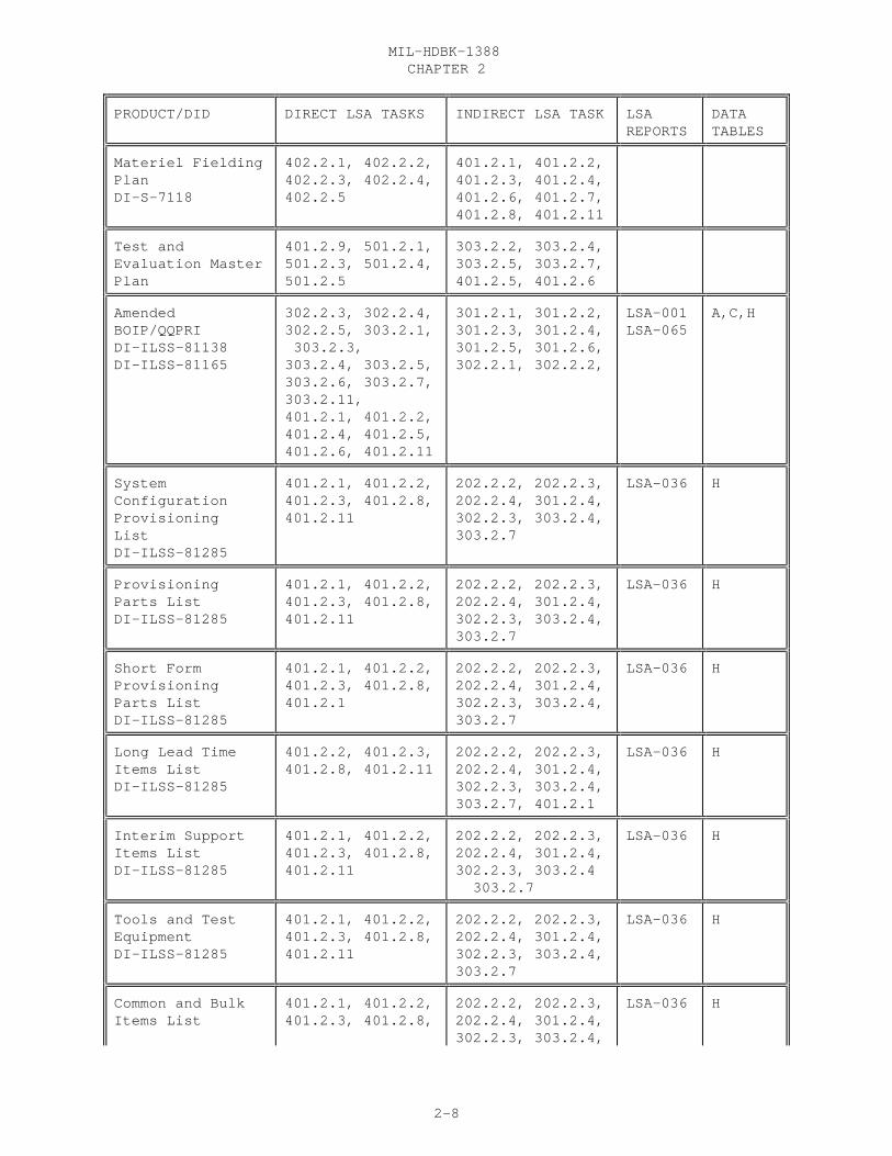
CHAPTER 2 MIL-HDBK-1388
2-8
PRODUCT/DID DIRECT LSA TASKS INDIRECT LSA TASK LSAREPORTS
DATATABLES
Materiel FieldingPlanDI-S-7118
402.2.1, 402.2.2,402.2.3, 402.2.4,402.2.5
401.2.1, 401.2.2,401.2.3, 401.2.4,401.2.6, 401.2.7,401.2.8, 401.2.11
Test andEvaluation MasterPlan
401.2.9, 501.2.1,501.2.3, 501.2.4,501.2.5
303.2.2, 303.2.4,303.2.5, 303.2.7,401.2.5, 401.2.6
AmendedBOIP/QQPRIDI-ILSS-81138DI-ILSS-81165
302.2.3, 302.2.4,302.2.5, 303.2.1, 303.2.3,303.2.4, 303.2.5,303.2.6, 303.2.7,303.2.11,401.2.1, 401.2.2,401.2.4, 401.2.5,401.2.6, 401.2.11
301.2.1, 301.2.2,301.2.3, 301.2.4,301.2.5, 301.2.6,302.2.1, 302.2.2,
LSA-001LSA-065
A,C,H
SystemConfigurationProvisioningListDI-ILSS-81285
401.2.1, 401.2.2,401.2.3, 401.2.8,401.2.11
202.2.2, 202.2.3,202.2.4, 301.2.4,302.2.3, 303.2.4,303.2.7
LSA-036 H
ProvisioningParts ListDI-ILSS-81285
401.2.1, 401.2.2,401.2.3, 401.2.8,401.2.11
202.2.2, 202.2.3,202.2.4, 301.2.4,302.2.3, 303.2.4,303.2.7
LSA-036 H
Short FormProvisioningParts ListDI-ILSS-81285
401.2.1, 401.2.2,401.2.3, 401.2.8,401.2.1
202.2.2, 202.2.3,202.2.4, 301.2.4,302.2.3, 303.2.4,303.2.7
LSA-036 H
Long Lead Time Items ListDI-ILSS-81285
401.2.2, 401.2.3,401.2.8, 401.2.11
202.2.2, 202.2.3,202.2.4, 301.2.4,302.2.3, 303.2.4,303.2.7, 401.2.1
LSA-036 H
Interim Support Items ListDI-ILSS-81285
401.2.1, 401.2.2,401.2.3, 401.2.8,401.2.11
202.2.2, 202.2.3,202.2.4, 301.2.4,302.2.3, 303.2.4 303.2.7
LSA-036 H
Tools and TestEquipmentDI-ILSS-81285
401.2.1, 401.2.2,401.2.3, 401.2.8,401.2.11
202.2.2, 202.2.3,202.2.4, 301.2.4,302.2.3, 303.2.4,303.2.7
LSA-036 H
Common and Bulk Items List
401.2.1, 401.2.2,401.2.3, 401.2.8,
202.2.2, 202.2.3,202.2.4, 301.2.4,302.2.3, 303.2.4,
LSA-036 H
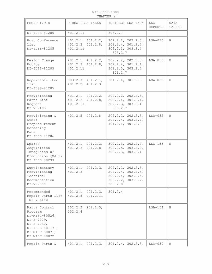
CHAPTER 2 MIL-HDBK-1388
2-9
PRODUCT/DID DIRECT LSA TASKS INDIRECT LSA TASK LSAREPORTS
DATATABLES
DI-ILSS-81285 401.2.11 303.2.7
Post ConferenceList DI-ILSS-81285
401.2.1, 401.2.2,401.2.3, 401.2.8,401.2.11
202.2.2, 202.2.3,202.2.4, 301.2.4,302.2.3, 303.2.4 303.2.7
LSA-036 H
Design ChangeNotice DI-ILSS-81285
401.2.1, 401.2.2,401.2.3, 401.2.8,401.2.11
202.2.2, 202.2.3,202.2.4, 301.2.4,302.2.3, 303.2.4 303.2.7
LSA-036 H
Repairable ItemList DI-ILSS-81285
303.2.7, 401.2.1,401.2.2, 401.2.3
301.2.4, 301.2.6 LSA-036 H
ProvisioningParts ListRequest DI-V-7193
401.2.1, 401.2.2,401.2.3, 401.2.8,401.2.11
202.2.2, 202.2.3,202.2.4, 301.2.4,302.2.3, 303.2.4 303.2.7
Provisioning &OtherPreprocurementScreeningData DI-ILSS-81286
401.2.5, 401.2.8
202.2.2, 202.2.3,202.2.4, 303.2.7,401.2.1, 401.2.2
LSA-032 H
SparesAcquisitionIntegrated w/Production (SAIP)DI-ILSS-80293
401.2.1, 401.2.2,401.2.3, 401.2.8
302.2.3, 302.2.4,302.2.5, 303.2.2,303.2.3, 303.2.4
LSA-155 H
SupplementaryProvisioningTechnicalDocumentation DI-V-7000
401.2.1, 401.2.2,401.2.3
202.2.2, 202.2.3,202.2.4, 302.2.3,302.2.4, 302.2.5,303.2.2, 303.2.7,303.2.8
RecommendedRepair Parts List DI-V-6180
401.2.1, 401.2.2,401.2.8, 401.2.11
301.2.4
Parts ControlProgram DI-MISC-80526,DI-E-7029,DI-E-7030,DI-ILSS-80117 ,DI-MISC-80071,DI-MISC-80072
202.2.2, 202.2.3,202.2.4
LSA-154 H
Repair Parts & 401.2.1, 401.2.2, 301.2.4, 302.2.3, LSA-030 H
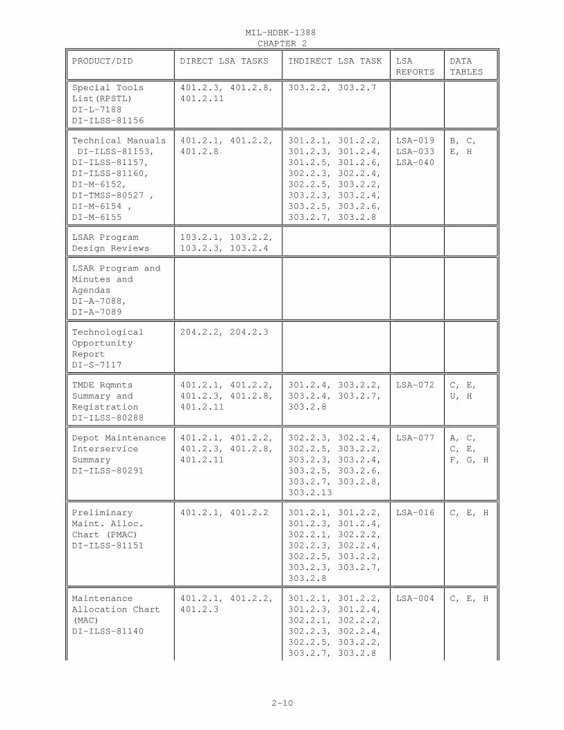
CHAPTER 2 MIL-HDBK-1388
2-10
PRODUCT/DID DIRECT LSA TASKS INDIRECT LSA TASK LSAREPORTS
DATATABLES
Special ToolsList(RPSTL) DI-L-7188DI-ILSS-81156
401.2.3, 401.2.8,401.2.11
303.2.2, 303.2.7
Technical Manuals DI-ILSS-81153,DI-ILSS-81157,DI-ILSS-81160,DI-M-6152,DI-TMSS-80527 ,DI-M-6154 ,DI-M-6155
401.2.1, 401.2.2,401.2.8
301.2.1, 301.2.2,301.2.3, 301.2.4,301.2.5, 301.2.6,302.2.3, 302.2.4,302.2.5, 303.2.2,303.2.3, 303.2.4,303.2.5, 303.2.6,303.2.7, 303.2.8
LSA-019LSA-033LSA-040
B, C,E, H
LSAR ProgramDesign Reviews
103.2.1, 103.2.2,103.2.3, 103.2.4
LSAR Program andMinutes andAgendas DI-A-7088,DI-A-7089
TechnologicalOpportunityReport DI-S-7117
204.2.2, 204.2.3
TMDE RqmntsSummary andRegistration DI-ILSS-80288
401.2.1, 401.2.2,401.2.3, 401.2.8,401.2.11
301.2.4, 303.2.2,303.2.4, 303.2.7,303.2.8
LSA-072 C, E,U, H
Depot MaintenanceInterserviceSummary DI-ILSS-80291
401.2.1, 401.2.2,401.2.3, 401.2.8,401.2.11
302.2.3, 302.2.4,302.2.5, 303.2.2,303.2.3, 303.2.4,303.2.5, 303.2.6,303.2.7, 303.2.8,303.2.13
LSA-077 A, C,C, E,F, G, H
PreliminaryMaint. Alloc.Chart (PMAC) DI-ILSS-81151
401.2.1, 401.2.2 301.2.1, 301.2.2,301.2.3, 301.2.4,302.2.1, 302.2.2,302.2.3, 302.2.4,302.2.5, 303.2.2,303.2.3, 303.2.7,303.2.8
LSA-016 C, E, H
MaintenanceAllocation Chart(MAC) DI-ILSS-81140
401.2.1, 401.2.2,401.2.3
301.2.1, 301.2.2,301.2.3, 301.2.4,302.2.1, 302.2.2,302.2.3, 302.2.4,302.2.5, 303.2.2,303.2.7, 303.2.8
LSA-004 C, E, H

CHAPTER 2 MIL-HDBK-1388
2-11
PRODUCT/DID DIRECT LSA TASKS INDIRECT LSA TASK LSAREPORTS
DATATABLES
Air ForceMaintenance PlanDI-ILSS-81183
401.2.1, 401.2.2,401.2.3
301.2.1, 301.2.2,301.2.3, 301.2.4,302.2.1, 302.2.2,302.2.3, 302.2.4,302.2.5, 303.2.2,303.2.7, 303.2.8
LSA-023 A, B,C, E, H
Navy MaintenancePlanDI-ILSS-80119B
401.2.1, 401.2.2,401.2.3
301.2.1, 301.2.2,301.2.3, 301.2.4,302.2.1, 302.2.2,302.2.3, 302.2.4,302.2.5, 303.2.2,303.2.7, 303.2.8
B, C,E, H
Support EquipmentRecommendationData(SERD)DI-ILSS-80118
401.2.3 303.2.2, 303.2.7,303.2.8
LSA-070 E, U,H, J
MANPRINT Report DI-ILSS-80290
301.2.4, 401.2.1,401.2.2, 401.2.3
301.2.1, 301.2.2,301.2.3, 303.2.2,303.2.3, 303.2.4,303.2.5, 303.2.6,303.2.7
LSA-075 A, C, G
FMECA Report DI-ILSS-81163
301.2.1, 301.2.2,301.2.3, 301.2.4
LSA-056 B, H
RCM SummaryDI-ILSS-81162
301.2.1, 301.2.2,301.2.3, 301.2.4
LSA-050 A, B,C, G
MaintainabilityPrediction ReportDI-MNTY-80827
301.2.4,401.2.1,401.2.2, 401.2.3
301.2.1, 301.2.2,301.2.3, 302.2.3,302.2.5, 303.2.2,303.2.3, 303.2.5,303.2.7, 303.2.8,303.2.11
MaintainabilityAnalysis ReportDI-MNTY-80828
301.2.4, 401.2.1,401.2.2, 401.2.3
301.2.1, 301.2.2,301.2.3, 302.2.3,302.2.5, 303.2.2,303.2.3, 303.2.5,303.2.7, 303.2.8,303.2.10,303.2.11
ReliabilityMathematicalModels DI-R-7081
301.2.4 301.2.1, 301.2.2,301.2.3
ReliabilityPrediction Models
301.2.4 301.2.1, 301.2.2,301.2.3

CHAPTER 2 MIL-HDBK-1388
2-12
PRODUCT/DID DIRECT LSA TASKS INDIRECT LSA TASK LSAREPORTS
DATATABLES
DI-R-7082
Logistic SupportAnalysis Plan DI-ILSS-80531
102.2.1, 102.2.2
NuclearSurvivabilityDI-ENVR-80266DI-ENVR-80267
301.2.4, 401.2.1,401.2.2
301.2.1, 301.2.2,301.2.3, 303.2.7,303.2.11
Level of RepairAnalysis (LORA)DI-ILSS-80654DI-ILSS-80655
301.2.4, 303.2.7 301.2.1, 301.2.2,301.2.3, 302.2.1,302.2.2, 302.2.3,302.2.4, 302.2.5,303.2.1
Calibration/Measurement RqmtSummaryDI-QCIC-80278DI-ILSS-81167
4012.1, 401.2.3,401.2.8, 401.2.11
302.2.3, 302.2.4,302.2.5, 303.2.2,303.2.8
LSA-076 A, C,E, U, H
Test Program SetsDI-A-6102DI-ATTS-80284DI-ILSS-80395DI-ATTS-80285
301.2.4, 401.2.1,401.2.2, 401.2.3
301.2.1, 301.2.2,301.2.3, 302.2.3,302.2.4, 302.2.5,303.2.13
Human FactorsEngineeringProgramDI-HFAC-80740DI-HFAC-80745DI -HFAC-80746DI-HFAC-80747DI-ILSS-81152
401.2.1, 401.2.2,401.2.3, 401.2.4,401.2.5
301.2.1, 301.2.2,301.2.3, 301.2.4,303.2.2, 303.2.5,303.2.6
LSA-018 C
Training Program DI-ILSS-81099 ,DI-ILSS-81070 ,DI-ILSS-81078, DI-ILSS-81150
401.2.1, 401.2.2,401.2.3, 401.2.4,401.2.11
301.2.1, 301.2.2,301.2.3, 301.2.4,302.2.3, 302.2.4,302.2.5, 303.2.2,303.2.3, 303.2.4,303.2.5, 303.2.6,303.2.7
LSA-014 C
Training ProgramDevelopment/Management Plan DI-ILSS-81070
401.2.1, 401.2.2,401.2.3, 401.2.4
303.2.5, 303.2.6
FacilitiesMaintenanceTraining Eqpmt
401.2.1, 401.2.2,401.2.3, 401.2.4
302.2.3, 302.2.4,302.2.5, 303.2.2,303.2.3, 303.2.4,

CHAPTER 2 MIL-HDBK-1388
2-13
PRODUCT/DID DIRECT LSA TASKS INDIRECT LSA TASK LSAREPORTS
DATATABLES
DI-H-6135 303.2.5, 303.2.6,303.2.7
Training CourseControl Document DI-ILSS-81075
303.2.2, 303.2.3,303.2.4, 303.2.8,401.2.1, 401.2.2
Test RequirementsDocumentDI-ATTS-80041
301.2.4, 401.2.1,401.2.2, 401.2.3
301.2.1, 301.2.2,301.2.3, 302.2.3,302.2.4, 302.2.5,303.2.13
Facilities PlanDI-ILSS-81148
301.2.4, 401.2.1,401.2.2, 401.2.3
301.2.1, 301.2.2,301.2.3, 302.2.3,302.2.4, 302.2.5,303.2.13
LSA-012 C, F
ComputerResources SupportDI-MCCR-80015DI-MCCR-80024DI-MISC-80711
401.2.1, 401.2.2,401.2.3, 501.2.1,501.2.3, 501.2.4
205.2.3, 302.2.3,302.2.4, 302.2.5,303.2.2, 303.2.5,303.2.6, 303.2.7
Packaging DataRequirementsDI-PACK-80120
401.2.1, 401.2.2,401.2.3, 401.2.8
LSA-025LSA-026
H
SupportabilityAssessment ReportDI-S-7121
501.2.4, 501.2.6
SupportabilityAssessment ReportPlan DI-S-7120
501.2.1, 501.2.3,501.2.5
TransportabilityReport DI-PACK-80880
401.2.7 303.2.12
TransportabilitySummaryDI-ILSS-81170
401.2.7 303.2.12 LSA-085 H, J
System SupportPackage ComponentList DI-ILSS-80532
501.2.2 303.2.5, 303.2.6,303.2.7, 303.2.8,303.2.13,401.2.1, 401.2.2,401.2.3, 401.2.4,401.2.7
LSAR Master Files
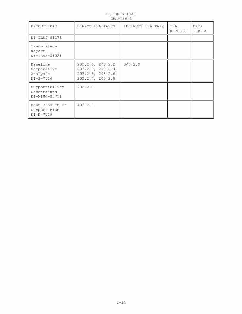
CHAPTER 2 MIL-HDBK-1388
2-14
PRODUCT/DID DIRECT LSA TASKS INDIRECT LSA TASK LSAREPORTS
DATATABLES
DI-ILSS-81173
Trade StudyReportDI-ILSS-81021
BaselineComparativeAnalysisDI-S-7116
203.2.1, 203.2.2,203.2.3, 203.2.4,203.2.5, 203.2.6,203.2.7, 203.2.8
303.2.9
SupportabilityConstraints DI-MISC-80711
202.2.1
Post Product onSupport PlanDI-P-7119
403.2.1

CHAPTER 2 MIL-HDBK-1388
2-15
20.3 CONTRACTING FOR LSAR 20.3.1 OBJECTIVE. Provide guidance on tailoring the LSAR data and reportingrequirements based on the specific needs of a weapon system program.
20.3.2 FACTORS TO CONSIDER. Figure2.1 lists some factors to considerwhen contracting for LSAR. Thefirst three factors; Type ofAcquisition, Phase of Developmentand LSAR Level of Effort are keyfactors when identifying thelogistic products required. The nexttwo factors; Previous LSAR Effortsand Degree of Program Control helprefine the logistics products andlogistic analyses reports that willbe needed for a weapon systemprogram.
20.3.2.1 TYPE OF ACQUISITION. Thetype of an acquisition program is amajor driver of LSAR cost. For LSARpurposes, most programs can beclassified into these areas:
a. Developmental Item. The most extensive LSAR programs generally fallinto this category since DOD has significant influence on the design of hardware and its support systems. In this type of acquisition all LSAR datashould be considered, but not all data may be purchased.
b. Streamline Development. This process is the same as a fulldevelopment. The major difference is that timing of data development becomesimportant. Again in this type of acquisition all LSAR data should beconsidered, but not all may be purchased
c. Product Improvement Program (PIP). For LSAR purposes, a PIP isdefined as the process by which an existing system is improved to the extentthat it will satisfy more stringent user requirements, provide improvedperformance, or significantly reduce logistic support and operating costs. PIP’s are good examples of how previous LSAR data can be used to lower theLSAR effort. The LSAR data is used as a baseline or starting point. Not allof the LSAR will have to be redone for a PIP. The LSAR should be tailored tosatisfy the needs for the new requirements identified by the PIP effort.
d. Non-Developmental Item (NDI). NDIs are systems available from avariety of sources requiring little or no development effort by thegovernment. NDIs include materiel developed and in use by other U.S. militaryservices or government agencies, and materiel developed and in use by othercountries, as well as commercially available materiel. All the LSAR data maynot need to be considered for a NDI or commercial off the shelf item. This isdependent on the item and what is available with that item. If there are good
FIGURE 2.1
CHAPTER 2 MIL-HDBK-1388
2-16
operator and repair manuals, then C tables may not need to be considered. Thesame hold true for provisioning information and reliability data.
20.3.2.2 PHASE OF DEVELOPMENT. Another consideration when developing aproduct list is the phase of development. Early on in the acquisition, in thefirst phase of development, the Requiring Authority (RA) concentrates ondeveloping requirements. Usually there is very little LSAR developed in thisphase. In the next phase there isn’t a need to consider or request detailedor final products, because tradeoffs are still being conducted. The analysiseffort provides initial information for documentation in the LSAR. The secondphase is a good place to request the analysis type LSAR reports. During thethird phase the design is firmed up and finalized. A detailed task analysiscan be accomplished in the fourth phase. In the third and fourth phases theLSAR data should be developed and finalized for the ILS products. The phaseof the life cycle is important when asking for data and will make a differencewhen asking for products.
20.3.2.3 LSAR LEVEL OF EFFORT. Levels of maintenance and hardware indentureshould be considered when deciding what LSAR products are needed for theacquisition. The levels of maintenance for the item under analysis have adirect effect on the LSAR. If the item is to be maintained at organizational,direct support, intermediate support, depot, or a special repair activity thenmanuals, spare, tools, test equipment, and man power for each of thesemaintenance levels must be considered. A level of repair analysis should bedone to correctly identify which of these maintenance levels are needed. Thatway the LSAR is keep to a minimum. The indenture level to which the hardwareis broken down will effect the LSAR. When a FMECA is documented it may lookdown to the major components or it may look down to the lowest repairableitem. Hence the level of effort is effected by hardware indenture level,because of the amount of documentation.
20.3.2.4 PREVIOUS LSAR EFFORTS. There may already be existing LSAR data forthis item, from another system or from a previous life cycle phase. The dataneeds to be reviewed to see if it is applicable to this system. Whenreviewing the data some of the areas to consider are format, level of effort,age, etc. The data may be in an acceptable/unacceptable format (e.g., In theprevious LSAR effort the format used was DARCOM 750-16, but now under thisdevelopment effort the format is MIL-STD-1388-2B). What must be considered inthis case is whether or not the data should be converted from the 750-16format to 2B format, there will be costs involved in converting this data. Again level of effort comes in to play. Is the level of effort in theprevious LSAR acceptable? Do you need to do analysis further on down, goingfrom LRU to piece part or from organizational and intermediated maintenancelevels to depot maintenance?
20.3.2.5 DEGREE OF PROGRAM CONTROL. Degree of program control is theconstraint placed on the developer in terms of control of the LSAR data. Thedata accession list can be used to look at data the developer has createdthrough his engineering process. This is the lightest degree of programcontrol. Reviewing the data on sight during formal design reviews is anotherdegree of program control. Another means of control, delivery of the mastertables, is when the reports and final products are produced in-house. Thetightest level of program control is when the developer is responsible for
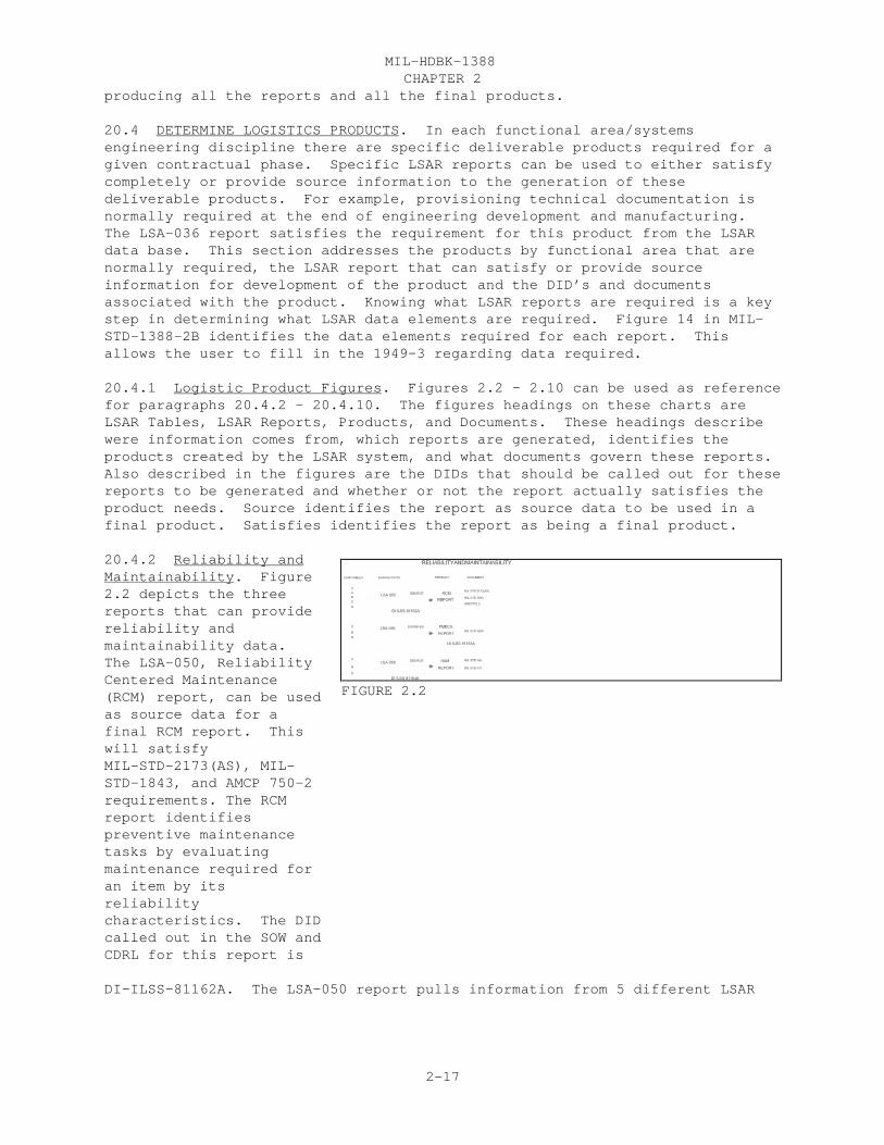
CHAPTER 2 MIL-HDBK-1388
2-17
producing all the reports and all the final products.
20.4 DETERMINE LOGISTICS PRODUCTS. In each functional area/systemsengineering discipline there are specific deliverable products required for agiven contractual phase. Specific LSAR reports can be used to either satisfycompletely or provide source information to the generation of thesedeliverable products. For example, provisioning technical documentation isnormally required at the end of engineering development and manufacturing. The LSA-036 report satisfies the requirement for this product from the LSARdata base. This section addresses the products by functional area that arenormally required, the LSAR report that can satisfy or provide sourceinformation for development of the product and the DID’s and documentsassociated with the product. Knowing what LSAR reports are required is a keystep in determining what LSAR data elements are required. Figure 14 in MIL-STD-1388-2B identifies the data elements required for each report. Thisallows the user to fill in the 1949-3 regarding data required.
20.4.1 Logistic Product Figures. Figures 2.2 - 2.10 can be used as referencefor paragraphs 20.4.2 - 20.4.10. The figures headings on these charts areLSAR Tables, LSAR Reports, Products, and Documents. These headings describewere information comes from, which reports are generated, identifies theproducts created by the LSAR system, and what documents govern these reports.Also described in the figures are the DIDs that should be called out for thesereports to be generated and whether or not the report actually satisfies theproduct needs. Source identifies the report as source data to be used in afinal product. Satisfies identifies the report as being a final product.
20.4.2 Reliability andMaintainability. Figure2.2 depicts the threereports that can providereliability andmaintainability data. The LSA-050, ReliabilityCentered Maintenance(RCM) report, can be usedas source data for afinal RCM report. Thiswill satisfyMIL-STD-2173(AS), MIL-STD-1843, and AMCP 750-2requirements. The RCMreport identifiespreventive maintenancetasks by evaluatingmaintenance required foran item by itsreliabilitycharacteristics. The DIDcalled out in the SOW andCDRL for this report is
DI-ILSS-81162A. The LSA-050 report pulls information from 5 different LSAR
FIGURE 2.2

CHAPTER 2 MIL-HDBK-1388
2-18
functional areas, shown in figure 2.2. The exact data elements called forthis report are in figure 14 appendix B from MIL-STD-1388-2B. The FMECAreport, LSA-056, report will satisfy MIL-STD-1629A’s requirement for a FMECAreport. The DID to use to get this report is DI-ILSS-81163A. This report canbe used to identify the results or effects of a potential failure on thesystem. The LSA-058 report can be used as source information for any type ofRAM report. It also can be used as a quick overview of most of the RAM typeinformation. The DID used to get this report is DI-ILSS-81164A.
20.4.3 MaintenancePlanning. Figure 2.3depicts the 5 reports thatcan provide informationfor maintenance planning. The LSA-004 report, theMaintenance AllocationChart (MAC), satisfies theArmy requirements laid outin MIL-M-63038 (TM). TheDID for this report isDI-ILSS-81140A. The MACprovides man-hourallocations by maintenancefunction and level. Alsoincluded in the MAC arethe tools and testequipment required by thetask function andmaintenance level. TheLSA-016 satisfiesDI-L-7190 for a Preliminary MAC (PMAC). The DID for this report isDI-ILSS-81151A. The report identifies tools and equipment by maintenancelevels needed to perform the maintenance functions, and to validate Source,Maintenance, and Recoverability (SMR) Codes for spares and repair parts. TheLSA-023 satisfies the requirements for an Air Force maintenance plan. The DIDfor this report is DI-ILSS-81183A. The report compares the requirements for asystem end item to the Reliability, Availability, and Maintainability (RAM)characteristics. It identifies the preventive and corrective maintenanceactions along with a listing of required support equipment for thosemaintenance actions. The LSA-024 satisfies the requirements for a Navymaintenance plan. The DID for this report is DI-ILSS-80119C. The reportidentifies general considerations, the required repair capabilities, andmaintenance tasks needed for the item under analysis. The LSA-033 reportsatisfies the requirements for a Preventive Maintenance Checks and Service(PMCS) for MIL-M-63038 (TM) and MIL-M-63036 (TM). The DID for this report isDI-ILSS- 81157A. This report provides operator/crew and organizational levelpreventive maintenance task identification, description, and whether or notthe equipment has full mission capability during the maintenance action.
FIGURE 2.3

CHAPTER 2 MIL-HDBK-1388
2-19
20.4.4 Technical Data and Manuals. Figure 2.4 depicts the reports used fordevelopment of technical manuals. The LSA-019 report is task narrative data andhas multiple options forselecting that report. The report can beselected by maintenancelevel, item category code(ICC)(s) , tasknarrative, hardnesscritical procedures, taskinterval, and taskfunction. This report issimilar to the tasknarrative master file in2A. It serves as feederdata to operators’ andmaintainers’ TechnicalManuals (TM). The DIDfor this report isDI-ILSS-81153A. TheLSA-030 report can beused for developing partsmanuals. It serves assource information forthe Repair Parts and Special Tools List (RPSTL) for the Army, the IllustratedParts Breakdown (IPB) for the Air Force and the Stockage List Type Four for theMarine Corps. These 3 products are part of the LSA-030 report and need to bespecified when asking for the LSA-030 report. The DID for this report is DI-ILSS-81156A. The Component of End Item List (COEIL), Basic Issue Items List(BIIL), Additional Authorization List (AAL), and Expendable Durable MaterialsSupply List (EDMSL) are also used as source data for TM development. Those fourlists and the Marine Corps Stockage List Type Three are contained in the LSA-040report. The DID for this report is DI-ILSS-81160A. Appendix B of Army TM’s willinclude the Maintenance Allocation Chart (MAC), the LSA-004 report. The LSA-033report will satisfy therequirements to develop anoperator/crew andorganizational level PMCSTM.
20.4.5 Support and TestEquipment. The reports,in figure 2.5, are usedwhen developing pieces ofsupport equipment. TheSupport EquipmentRecommendation Data (SERD)report, LSA-070, describesrequirements for a piece
of support equipment. The DID for this reportis DI-ILSS-80118C. The
FIGURE 2.4
FIGURE 2.5

CHAPTER 2 MIL-HDBK-1388
2-20
LSA-071, Support Equipment Candidate List, provides a list of supportequipment requirements by active and disapproved candidates. The DID for thisreport is DI-ILSS-81166A. The LSA-074 report, Support Equipment Tool List,provides a list of tools currently in the inventory and tools that are not inthe inventory, but need to be developed. The DID for this report isDI-ILSS-80289B. These three reports satisfy the requirement established byMIL-STD-2097. When a piece of support equipment needs to be registered in theArmy inventory, use the LSA-072 report, Test Measurement and DiagnosticEquipment (TMDE) Registration. The DID for this report is DI-ILSS-80288B. Tosatisfy MIL-STD-1839 use the LSA-076 report, Calibration Measurement andRequirement Summary (CMRS). The DID for this report is DI-ILSS-81167A. Thisreport provides details of the TMDE and its calibration procedures.
20.4.6 Supply Support. Figure 2.6 identifies two of the reports used in thesupply support area. During the engineering design effort there will berequirements for screening parts thru Defense Logistic Service Center (DLSC)files. This is used to identify any new parts, brought about by the designeffort. The new parts identified by this process will be introduced into themilitary inventory. DLSC screening canidentify a part thatalready exists in theinventory. The DID forthis report is DI-ILSS-81286. The LSA-036report provides theselists for provisioningrequirements: Provisioning Parts List(PPL); Long Lead TimeItems List (LLTIL);Repair Item List (RIL);Interim Support ItemsList (ISIL); Tools andTest Equipment List(TTEL); Common and BulkItems List (CBIL);Design Change Notices(DCN); SystemConfiguration Provisioning List (SCPL); Short Form Provisioning Parts List(SFPPL); and Post Conference List (PCL). The lists produced by the LSA-036report satisfy the requirements of MIL-STD-1388-1A, Notice 4. The DID forthese Provisioning lists is DI-ILSS-81285.
20.4.7 Supply Support (continued). These 3 reports, figure 2.7, are used todocument supply support. There may be a need to check the LSAR data against adrawing. This would be done to make sure that every part within the drawingbreakdown is within the LSAR. The LSA-080 report would be used for this purpose. The DID for this report is DI-ILSS-81169A. The LSA-151 reportprovides a cross reference between referenced number and the applicable
FIGURE 2.6
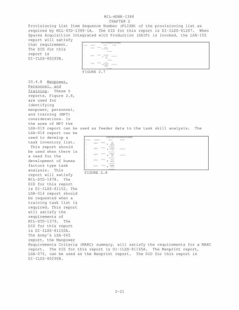
CHAPTER 2 MIL-HDBK-1388
2-21
Provisioning List Item Sequence Number (PLISN) of the provisioning list asrequired by MIL-STD-1388-1A. The DID for this report is DI-ILSS-81287. WhenSpares Acquisition Integrated with Production (SAIP) is invoked, the LSA-155report will satisfythat requirement.The DID for thisreport isDI-ILSS-80293B.
20.4.8 Manpower,Personnel, andTraining. These 5reports, Figure 2.8,are used foridentifyingmanpower, personnel,and training (MPT)considerations. Inthe area of MPT theLSA-019 report can be used as feeder data to the task skill analysis. TheLSA-018 report can beused to develop atask inventory list. This report shouldbe used when there isa need for thedevelopment of humanfactors type taskanalysis. Thisreport will satisfyMIL-STD-1478. TheDID for this reportis DI-ILSS-81152. TheLSA-014 report shouldbe requested when atraining task list isrequired. This reportwill satisfy therequirements ofMIL-STD-1379. TheDID for this reportis DI-ILSS-81150A. The Army’s LSA-065report, the ManpowerRequirements Criteria (MARC) summary, will satisfy the requirements for a MARCreport. The DID for this report is DI-ILSS-81165A. The Manprint report,LSA-075, can be used as the Manprint report. The DID for this report isDI-ILSS-80290B.
FIGURE 2.7
FIGURE 2.8

CHAPTER 2 MIL-HDBK-1388
2-22
20.4.9 Facilities. In the area offacilities, Figure2.9, the LSA-012report can be usedto identify thefacilities neededto do maintenancetasks and training. This report can beused by theservices to developtheir servicepeculiar facilityrequirements. TheDID for this reportis DI-ILSS-81148A. The LSA-077 reportshould be used whenthere is a need fora joint depotmaintenancefacility. This report can be used to satisfy those requirements of JCL Forms28/29/30. The DID for this report is DI-ILSS-80291B
20.4.10 Packaging, Handling, Storage, and Transportability. Figure 2.10identifies thereports that can beused in thepackaging, handling,storage, andtransportation areas. The LSA-025 reportand LSA-026 reportcan be used toidentify thoserequirements forpackagingdevelopmental dataand packagingrequirements data. These reports willsatisfy therequirements ofMIL-STD-2073-1. TheDIDs for thesereports areDI-PACK-80120 andDI-ILSS-81154A,respectively. TheLSA-085 report willprovide source datato the transportability report. The DID for this report is DI-ILSS-81170A.
FIGURE 2.9
FIGURE 2.10

CHAPTER 2 MIL-HDBK-1388
2-23
20.5 LSAR Analysis Reports. There may be times when a product report is notneeded and an analysis report will suffice. These analysis type reports canbe used to analyze different logistic needs. These next paragraphs describethe analysis reports and identifies the DIDs associated with each report.
20.5.1 LSA-001, Annual Man-Hours by Skill Specialty Code and Level ofMaintenance. The report is divided into two parts. It is used to determinemanpower requirements of the system/equipment, and to determine the timerequired and number of personnel, by Skill Specialty Code (SSC), and personidentifier to perform each task. Part I contains a summary of annual man-hourexpenditures by maintenance levels and SSC. Man-hour totals are based on thenumber of systems supported by level of maintenance. Part II contains areport of the man-hours, by person identifier, expended on each maintenancetask. The DID for this report is DI-ILSS-81138A.
20.5.2 LSA-003, Maintenance Summary. This report compares the current statusof the system maintenance parameters with the requirements recorded on the Adata tables. The DID for this report is DI-ILSS-81139A.
20.5.3 LSA-005, Support Item Utilization Summary. This report, by ICC, showsthe use of the item by maintenance level and LCN. The report should be usedto justify the requirement for support equipment and determine the quantityand distribution requirements. The report should also be used to determinerecommended order quantities of repair parts based on their total use. TheDID for this report is DI-ILSS-81141A.
20.5.4 LSA-006, Critical Maintenance Item Summary. This report provides alist of all maintenance tasks which exceed a specific value for taskfrequency, or elapsed time, or man-hours, or annual man-hours. The specificvalue(s) exceeded is identified as critical criteria. The report may beselected for any maintenance level or combination of levels and for scheduledor unscheduled maintenance. The report should be used to pinpoint problemareas and plan maintenance for critical components. The DID for this reportis DI-ILSS-81142A.
20.5.5 LSA-007, Support Equipment Requirements. This is a report of allsupport equipment (i.e., tools, test equipment, etc.) utilized by SSC andlevel of maintenance. The report may be selected for any maintenance level orcombination of levels. This report should be used to develop tool kits foreach skill specialty at each level of maintenance. The DID for this reportis DI-ILSS-81143A.
20.5.6 LSA-008, Support Items Validation Summary. This summary provides alisting of those support items required to support/perform the task at eachmaintenance level. The support items are categorized in groups of: Support/Test Equipment and Tools (ICC D, G, H, M, N, P, R, V, 1-8, AC) Spare and Repair Parts (ICC X, Y, Z, 9, AA, AB, AE) Other (ICC, E, F, J, Q, S, T, W, AD)This summary should be used to review support items requirements for themaintenance and operator task(s) involved and may be selected for an entireequipment, specific LCN range, maintenance level, or ICC(s). The DID for this

CHAPTER 2 MIL-HDBK-1388
2-24
report is DI-ILSS-81144A.
20.5.7 LSA-009, Support Items List. This is a report by LCN, referencenumber, and national stock number (NSN), of all repair parts, tools/testequipment necessary to support the system/equipment. The report should beused to provide information necessary to assist in performing provisioning. The DID for this report is DI-ILSS-81145A.
20.5.8 LSA-010, Parts Standardization Summary. This is a report by referencenumber of all spare and repair parts comprising the system/equipment. It canbe utilized to assist in performance of DOD Replenishment Parts BreakoutProgram. The DID for this report is DI-ILSS-81146A.
20.5.9 LSA-011, Requirements for Special Training/Device Summary. This is areport of all operator or maintenance tasks, which have been identified asrequiring a special training device and the narrative explanation of thetraining equipment requirement. The report should be used to identify therequirements, and provide justification, for the acquisition of trainingdevices. The DID for this report is DI-ILSS-81147A.
20.5.10 LSA-013, Support Equipment Grouping Number Utilization Summary. Thisis a report by maintenance level and Support Equipment Grouping IdentificationNumber of the tasks, which use the support equipment group. The report shouldbe used to provide the requirements, quantity, and justification for theacquisition of support equipment. The DID for this report is DI-ILSS-81149A.
20.5.11 LSA-027, Failure/Maintenance Rate Summary. This report identifies anitem and annual operating requirements by LCN and task code. This reportshould be used to provide information necessary to monitor failure rates,failure modes, task frequencies, and MRRs. The DID for this report isDI-ILSS-81155A.
20.5.12 LSA-037 Spares and Support Equipment Identification List. Thepurpose of this report is to provide information that identifies theinvestment spares (Section I), expense spares (Section II), support equipment(Section III), and tools and test equipment (Section IV) required for systemsupport under contractor logistic support. The DID for this report isDI-ILSS-81158A.
20.5.13 LSA-039, Critical and Strategic Item Summary. This is a report ofitems assigned a critical item code (CIC) or industrial materials analysis ofcapacity (IMAC) code. Part 1 of the report lists CIC items. Part 2 of thereport lists IMAC items. The DID for this report is DI-ILSS-81159A.
20.5.14 LSA-046, Nuclear Hardness Critical Item Summary. This summaryprovides a listing of all support items which are coded as nuclear hardnesscritical. The DID for this report is DI-ILSS-81161A.
20.5.15 LSA-078, Hazardous Materials Summary. This report provides a summaryof all hazardous materials required to support a selected end item. Thissummary identifies all items having associated hazardous materials storagecost, hazardous waste storage cost, and hazardous waste disposal costs. Thissummary also identifies the maintenance tasks requiring quantities and costs
CHAPTER 2 MIL-HDBK-1388
2-25
per task. The summary is used to eliminate or reduce identified hazardousmaterial items during the system design process. The DID for this report isDI-ILSS-81168A.
20.5.16 LSA-126, Hardware Generation Breakdown Tree. This summary provides aconcise summary of information pertaining to a system/equipment breakdown. Each item is blocked in and indented to the proper level in the hardwarefamily tree and displayed by line relationship beneath the appropriateassembly in which the item is contained. The DID for this report isDI-ILSS-81171A.
20.5.17 LSA-152, PLISN Assignment/Reassignment. This summary provides alisting, by reference number, of PLISN, Indenture Code (IC), Next HigherAssembly (NHA) PLISN, and PRIOR ITEM PLISN, assigned by the LSAR system basedon parameters of the assignment select card. The summary is automaticallyproduced and will depict the file content before and after the assignments orreassignments are made (PLISNs are assigned using the EBCDIC collatingsequence). As an option, this report can be used to assign provisioningrelated control and reference data to the LSAR Master Table. The DID for thisreport is DI-ILSS-81172.
20.5.18 LSA-154, Provisioning Parts Breakout Summary. This report provides atwo-part summary of each reference number and can be utilized to assist inperformance of the DOD Replenishment Parts Breakout Program. Included in partI of the report are critical pricing and breakout program information. PartII contains selected parts application data. The DID for this reportis DI-ILSS-80292B.
20.6 AD-HOC Queries. If neither product or analysis reports can satisfy arequirement AD-HOC Queries are another option. AD-HOC reports can be created,when using a Relational Data Base Management System (RDBMS), to satisfy arequirement when it can not be satisfied by the standard reports. MIL-STD-1388-2B, Appendix A, data tables, were developed in a relationalship formatand should reside on a RDBMS. Most RDBMS use Structured Query Language (SQL)for AD-HOC capabilities. Some have advanced capabilities to help buildqueries without knowing SQL.
20.6.1 Example AD-HOC Query. Since SQL is the basic query language of allRDBMS it will be used to develop an example query. In this example there is aneed to compare the 3rd and 4th positions, maintenance levels, of the SMR codeto the 3rd position, maintenance level of the task code. This requirement cannot be satisfied by LSAR reports; therefore, an AD-HOC query is required forthis comparison. The AD-HOC query, using SQL, would look like this
1 SELECT HG.EIACODXA, HG.LSACONXB, HG.ALTLCNXB, HG.CAGECDXH, HG.REFNUMHA,HG.SMRCODHG, CA.TASKCDCA2 FROM CA, HG3. WHERE HG.EIACODXA = CA.EIACODXA4 AND HG.LSACONXB = CA.LSACONXB5 AND HG.ALTLCNXB = CA.ALTLCNXB6 AND HG.LCNTYPXB = CA.LCNTYPXB
This simple query will print out the End Item Acronym Code (EIAC), LCN, ALC,

CHAPTER 2 MIL-HDBK-1388
2-26
Commercial and Government Entity Code (CAGE), Reference Number, SMR Code, andTask Codes. The comparison can then be done manually. To do a comparisonautomatically would be a more in depth query which should be developed by aprogrammer.
20.7 DD Form 1949-3, LSAR Data Requirements Form. When the reports neededfor either products or analysis are identified, the DD Form 1949-3 can becompleted. To fill out the 1949-3 use figure 14 in appendix B of MIL-STD-1388-2B, to identify the data elements needed for the reports.
20.7.1 Data Element Selection. The best way to show how the data elements areselected is by example. In this example a FMECA report, LSA-056 report, isrequired by the reliability community. The first step is to use figure 14, inappendix B, of MIL-STD-1388-2B or figure 2.11 (an excerpt from figure 14 andDD Form 1949-3) to identify the data elements and their corresponding tables. To identify the data elements needed for the LSA-056 report look across thetop of figure 2.11 and identify the LSA-056 report column. Next identify thedata elements that have a mark in that column. If a data element has any markin the column then it should be marked as required on the DD Form 1949-3.
20.7.2 Selection of 1949-3 Data Elements. The LSAR data requirements form(DD Form 1949-3) provides a vehicle for identifying the required LSAR dataelements to be completed and, when applicable, the media of delivery.Preparations of the LSAR data requirements forms should be a result of theLSAR tailoring process. The data requirements form can be used to identifythe specific data elements that are required and identified on the relationaldata tables. DD Form 1949-3, LSAR data requirements form is referenced byparagraphs 4.1, 5.1, and 5.2 in the main body of MIL-STD-1388-2B.
20.7.2.1 DD Form 1949-3 Sections and Parts. The 1949-3 consists of a generalinformation section plus two other sections. The first section consists of RAfurnished data. Spaces are provided to allow the RA to fill in values forthese data elements. The second section consists of the LSAR data selectionsheets and is divided into three parts. Part I is the LSAR data selected byan entry in the Required column. Part II is the LSAR provisioning dataselected by an entry in the required column and the type of provisioning list. Part III is packaging data selected by an entry under a packingcategorization.
20.7.2.2 DD Form 1949-3, General Information. The general informationsection of the 1949-3 explains the codes appearing in the key column of thedata selection sheets. These key codes are designed to make the selection ofdata a non burdensome process. The media selection, the header, andsequencing, provisioning lists, and provisioning guidance conferenceinformation are also in this section.
20.7.2.3 Section 1 of DD Form 1949-3, Government Furnished Data. This sectionconsists of the data elements that should be provided by the RA. The firstsheet, page 4, consisting of information from tables XA, AI, AJ, and AK whichpertains to the end item. This sheet should be filled out once for each enditem documented in the LSAR. The second sheet, pages 5 and 6, should befilled out by the RA and pertains to the item or LCN under analysis. Thissheet may filled out against any item or LCN for which the RA feels should be

CHAPTER 2 MIL-HDBK-1388
2-27
given to the developer. There may be numerous sheets identifying theinformation for each item or LCN for these tables XB, XC, AA, AB, AC, AD, AE,AF, AG, and AH. The third sheet, page 7, consisting of information formtables EA and EB, it should be filled out by the RA and pertains to one pieceof support equipment that is or will be supporting the item under analysis. The forth sheet, page 8, consisting of information from tables UA, HA, HG, andHP should be filled out by the RA and pertain to the item under analysis.
20.7.2.4 Peculiarities of the 1949-3. Part I of section 2, of the 1949-3,consists of data pertaining to the item(s) under analysis. The information isgrouped in relationalship table format, for functional area’s (X, A, B, C, E,U, F, G, H, and J tables) . There are peculiarities of DD Form 1949-3,figure 2.11, that should be pointed out. It must be understood that as thetables progress from parent to child the data element which were keys in theparent table are then dropped off of the child table (e.g. XA table, EIAC isdropped when the information is used in the XB table). It also means thatwhen information is selected in a child table there should be a concertedeffort to make sure that the keys which form the parent tables are selected. This holds true within a functional area. At the start of each functionalarea the main set of keys will be duplicated (e.g. BA table has End ItemAcronym Code, LCN, ALC, and LCN Type all which originate in the X tables) thisis done to facilitate the parent to child relationships between functionalareas.
20.7.2.4.1 Data Element Selection. Selection of a data element shallconstitute the selection of data keys or data dependencies required todocument the element in the LSAR data base. One thing that must be stated isthat the only mandatory data elements for a report are the ones identified bya F, K, * or M in the report column of figure 14, MIL-STD-1388-2B. Where morethan one data element code applies to a data selection, the code columncontains dashes (----) (e.g. Table XA, Personnel Turnover Rate is divided intotwo categories civilian and military, but is included under one data elementdefinition). For narrative data, where each data element definition isseparately selectable to a common data table, the code column is blank (e.g.Table BB, RAM Characteristics Narrative; Item Function, Maintenance Concept,Minimum Equipment List Narrative, Qualitative and Quantitative MaintainabilityRequirements, and Maintenance Plan Rationale are narrative data and theircorresponding code fields are blank). Text sequencing codes for narrative,measurement bases and unit of measures are not show in the 1949-3 because theyare required for the narrative or numeric data element to exist in the database. There are exception to this rule for measurement base and unit ofmeasure, this exception occurs only when the measurement base or unit ofmeasure is a key in that table.
20.7.2.5 Data Element Selection DD Form 1949-3 Example. Figure 2.11 showsthe data elements needed for the FMECA report, LSA-056, from figure 14 of MIL-STD-1388-2B, and transfers the selected data elements to the 1949-3. First identify the LSA-056 column, then find the data elements that have a mark nextto them. If the data elements have any mark by them then they are needed forprocessing or can be output on the LSA-056 report. The first data element,

CHAPTER 2 MIL-HDBK-1388
2-28

CHAPTER 2 MIL-HDBK-1388
2-29

CHAPTER 2 MIL-HDBK-1388
2-30

CHAPTER 2 MIL-HDBK-1388
2-31

CHAPTER 2 MIL-HDBK-1388
2-32

CHAPTER 2 MIL-HDBK-1388
2-33

CHAPTER 2 MIL-HDBK-1388
2-34
EIAC, needed for the LSA-056 report is pulled from the XA table. The nextdata elements needed for the LSA-056 report are LCN, ALC, LCN Type, LCNNomenclature, Technical Manual/Functional Group Code (TM/FGC), and theReliability, Availability, and Maintainability (RAM) Indicator. Now look atthe 1949-3, notice that the EIAC doesn’t exist in the XB table and that’sbecause the EIAC doesn’t originate in the XB table. When a data element is akey it only shows on the 1949-3 in the table in which it originated. Find thenext table that has a mark in the 56 report column. The next table is XC, the56 report requires the use of the UOC and Provisioning Contract Control Number(PCCN). The PCCN is selected for the 56 report because it is a mandatory dataelement in the XC table. Mark the UOC and PCCN in the XC table on the 1949-3. The XF and XG tables are needed for system processing so they must be markedon the 1949-3. The cage code is needed from the XH table so it must be markedalso. The next data elements marked as required is the EIAC, LCN, ALC, andLCN type from the BA table so mark them on the 1949-3. (NOTE A; These mainset of keys that establish a functional area are repeated again on the 1949-3. The EIAC is established in the XA table and the LCN, ALC, and LCN Type areestablished in the XB table, and are marked accordingly, but they are alsomarked at the start of a functional area. The RA should not pay for thesedata elements again, because they were already established in the crossfunctional area.) Only one other data element is needed from the BA table andthat’s the failure rate data source, so it needs to be marked on the 1949-3. The next data elements to be marked on the 1949-3 are the RAM charactersnarrative code and the RAM minimum equipment list narrative from the BB table. (NOTE B; On all narrative tables, such as the BB table, the Narrative codemust be selected to identify which narrative is needed for the report). TheLSA-056 report also requires information from the BC table in the form ofLogistic Consideration Code and the logistic narratives associated with thesecodes. The LSA-056 needs additional information form the BD table in the formof the RAM indicator code, failure rate and failure rate measurement base(MB). (NOTE C; In all cases the measurement base for any item is automaticallyselected when the item its associated with is selected. This is very similarto Note B in that on the 1949-3 there is not a failure rate MB to select, butis inherently selected when the failure rate is selected. Both the item andits MB must be used for the item to pass ADP system requirements.) Failuremode indicator, engineering failure mode Mean Time Between Failure (MTBF), andfailure mode ratio are selected from the BF table and should be marked on the1949-3. The BG table is similar to the BB table. The Failure Mode andReliability Centered Maintenance (RCM) narrative code is needed to distinguishbetween the narratives from the BG table on the 56 report. The narrativesneeded are: failure damage mode effect local, next higher and end effect;failure cause; failure damage mode; failure mode detection method; failuremode predictability; failure mode remarks; and redesign recommendationsnarrative. The task requirement LCN, task requirement ALC, task requirementLCN Type, task code, and task type are needed from the BH table. (Note D; Thetask requirement LCN, task requirement ALC, task requirement LCN Type, andtask code originate in the CA table, but to tie the repair tasks to theirfailures are shown in the BH table also.) The Safety Hazard Severity Code(SHSC), Failure Effect probability, Failure Mode Criticality Number, FailureProbability Level, and Operation Time are selected from the BI table. Thenarrative compensating design provisions and compensating operator actions areselected from the BJ table. The RAM SHSC and Item Criticality Number areselected form the BK table. The Mission Phase code and Mission Phase
CHAPTER 2 MIL-HDBK-1388
2-35
Operation Mode are selected from the BL table. Reference back to Notes A andD, EIAC, LCN, ALC, LCN type, and Task Code are selected from table CA. Alsoselected from the CA table are the referenced LCN and AOR LCN. The Cage Code,Reference number, Reference Number Category Code (RNCC), Reference NumberVariance Code (RNVC) are needed by the 56 report, from table HA, to identifythe Drawing Number; therefore, they are selected on part II of the 1949-3. There is also a possibility that there is alternate or additional drawingnumbers for the item under analysis and those alternate or additional drawingnumbers are pulled from the HB table in part II. To pull these additionaldrawing numbers the Additional Reference Number (ARN) CAGE Code, ARN ReferenceNumber, ARN category Code, and ARN Variance Code must be selected from the HBtable. The last data elements required for the 56 report are the EIAC, LCN,ALC, and LCN type from table HG. This is where the LCN for the item and thereference number for the item are tied together for part application. Thistable is used as a link to get the drawing number needed for the LSA-056report.
20.8 Delivery of LSAR Data. The delivery of LSAR data can consist of hardcopy, master tables, on-line access or a combination of all three. Each ofthese delivery options should be considered carefully. What is provided nextis a description of each option and its pro’s and con’s.
20.8.1 Hard Copy LSAR Reports. The RA and MD can ask the developer todelivery hard copies of the product, analysis or AD-HOC reports to be used asproducts or as inputs into final products or analysis reports. The RA and MDwould request these reports, who should receive them, any specific selectionoptions, when delivered, and the report DID numbers should be called out on DDFORM 1426, CDRL. A statement could be made in the SOW that states the reportsshould be delivered in accordance with the CDRL.
PRO’S. The RA and MD can hold thedeveloper accountable for the finalproducts.
CON’S. The RA and MD will have topay for each delivery and paperreport. These usually containoutdated information. The RA and MDwill have to create the AD-HOC queryor request that the developer createit.
20.8.2 Master Table Delivery. The RA and MD may request that the mastertables be delivered so that the different LSAR products, analysis, ordeveloped AD-HOC reports can be produced. The RA and MD would request themaster tables, who should receive them, when delivered, format and the mastertable DID number on DD FORM 1426, CDRL. A statement could be made in the SOWthat states the master tables should be delivered in accordance with the CDRL. The RA and MD will need a MIL-STD-1388-2B validated LSAR ADP system toproduce these reports.
PRO’S. Cost wise it is toward theRA’s and MD’s advantage, if they

CHAPTER 2 MIL-HDBK-1388
2-36
have a 2B LSAR ADP system, to havethe developer provide the mastertables for loading into the RA’s andMD’s ADP system. The RA and MD canproduce the reports and as many ofthe reports as needed.
CON’S. The RA and MD can not holdthe contractor accountable for thefinal products. The master tableswill need to be updatedincrementally to show the latestdata. Again there will be some lagtime for the data. The RA and MDwill be responsible for the AD-HOCquery development.
20.8.3 On-Line Access. The RA and MD may request the capability of on-lineaccess to review the LSAR data without a need for paper products. The RA andMD would request this capability in the SOW. There are considerations foron-line access. The RA and MD should decide if these considerations should beput in the SOW. The consideration are: is there a need for communicationhardware or software to access the developers database, how many users willthere be, are there any interfacing requirements with other databases, willthere be a dedicated line, will people need training on how to access thedatabase and run standard and ad-hoc reports, security issues, who has accessto the computer, and on-line comment capability. These are the things thatmust be considered and specified in the Statement of work when a developerprovides these service to the RA and MD.
PRO’S. The RA and MD will have thelatest information. The RA and MDwill be able to make comments, onthe data in the data base, on-line. The on-line comment capability willmean a reduction in TDY costs. TheRA and MD can produce the product,analysis and AD-HOC reports whenrequired. On-site reviews arereduced.
CON’S. There will be additionalcosts for this on-line accesscapability.
20.8.4 Delivery Combination. The RA and MD may want the best of all worlds. He may want to have on-line access, with the master tables delivered at theend of the phase, and have the developer responsible for certain productreports. The RA and MD would request the master tables and reports, who wouldreceive them, when delivered, selection options, delivery format, and DIDnumbers on DD FORM 1426, CDRL. The on-line access capabilities and anyspecial requirements associated with these capabilities would be documented inthe SOW.
PRO’S. The RA and MD can hold thedeveloper accountable for some ofthe most important final products. The RA can have the master filesfor historical purposes. He canhave up to date information usingthe on-line access capability.
CON’S. Cost.
20.9 Example Statement of Work. This is an excerpt from a SOW produced byLogistics Planning and Requirements Simplification System (LOGPARS) concerningthe documentation of data in the LSAR and the different possible delivery

CHAPTER 2 MIL-HDBK-1388
2-37
modes.
C.3.4. Logistic Support Analysis Record (LSAR). LSAR Data.
a. Data and information generated from the LSA program tasks shall bedocumented and maintained in the LSAR IAW MIL-STD-1388-2B, and therequirements contained herein. The LSAR shall be developed as the centralfile of validated, integrated and design related logistic data for thesystem. The LSAR shall be maintained as specified in the approved LSA planand herein. The LSAR shall be used to satisfy applicable and related dataitems as specified in the CDRL.
b. The contractor shall update LSAR documentation to reflect changes insupport requirements resulting from:
(1) Changes to equipment design, support or operationalrequirements as a result of logistic demonstration, TM reviews, trainingresults, contractor/government testing or other ILS considerations.
(2) Logistic support improvements or the correction of deficienciesdiscovered through analysis of test results or by the contractor’sverification of LSAR documentation. (3) ILSMT/LSAR review team recommendations.
c. The contractor shall assign LCNs to individual equipment items tofacilitate data storage and retrieval. The structure of the number shallrepresent a hardware generation breakdown of the hardware and will includesupport and test equipment, training equipment, and installation hardwareitems. Each item of equipment, from the end item down to each individualpiece part shall be assigned a unique LCN. The LCN will be assigned for eachapplication of the item throughout the system to identify its relationship tothe next higher assembly. The LCN structure must agree with the hardwarebreakdown as it will be displayed in the engineering drawings for theequipment. The contractor is responsible for ensuring the compatibility andintegration of subcontractor/vendor LCNs within the overall codingarrangement. The first character of the LCN may be assigned by the procuringagency to maintain compatibility with the Work Breakdown Structure (WBS)codes, the Commodity Command Standard System (CCSS), and other governmentmanagement information system requirements. The contractor’s proposednumbering system shall be described in the LSA plan and requires governmentapproval.
d. The contractor shall establish and maintain automated sets of LSARdata for the management and control of the LSAR. As a minimum, thecontractor shall maintain a set of LSAR review data and a set of governmentapproved LSAR data. The LSAR data in the review set shall be data that hasbeen subjected to the internal contractor review procedures and frozenpending review and approval by the government. The LSAR review data shall beupdated with new additions on a weekly frequency regardless of the approvalstatus of their content since the last update. Upon government approval,LSAR data contained in the review data set shall be transferred to thegovernment approved LSAR data set. All government-directed changes resulting

CHAPTER 2 MIL-HDBK-1388
2-38
from LSAR reviews shall be incorporated prior to the relocation of the data.The government approved LSAR data shall be cumulative of allgovernment-approved LSAR data.
The contractor shall provide LSAR output reports and LSA master files in thefollowing forms: - hard copy
In addition to the predefined LSAR output reports, the contractor shallestablish and maintain the capability for on-line ad hoc query/reportgeneration. AD HOC reporting capabilities shall be defined by thecontractor’s LSAR ADP system software and presented in the LSA portion of theproposal. As a minimum, the ad hoc report generation shall be capable ofkeying on and displaying all LSAR data elements as identified on the attachedDD Form 1949-3.
The software will provide the capability for terminal display of thespecified queries or data files in 80 and/or 132 character format and willinclude the capacity to print the queries on a local printer at thedesignated locations. The user shall have the capability to specify queriesfrom the review data set, the approved data set, or a combination of the two.The contractor shall provide the Government with interactive accesscapability Monday thru Friday 0800-1700. Government use of the accesscapability shall be limited as described below:
Access shall be limited to the following location: - LOGSA, Huntsville, AL
The contractor shall establish the telecommunications capability using one ormore of the following methods and shall establish a means for ensuringcompleteness and accuracy of data transmissions: - Point-to-point dedicated lines
In addition, the contractor shall provide: - hardware and software for each of the designated locations
Data Interface. The LSAR shall be used to the maximum extent feasible tosatisfy requirements for deliverable data as listed on the current CDRL andfor future deliverable data requirements.
o Maintenance Allocation Chart (MAC) IAW the CDRL. LSA-004, MaintenanceAllocation Chart shall be utilized as the data base to satisfy the CDRL for aMAC. The LSAR will be used to produce both of these reports in "proof"version in conformance with the requirements of MIL-M-63038B.
o Provisioning Technical Documentation. The contractor shall plan forand provide provisioning requirements IAW provisioning procedures as statedin MIL-STD-1388-2B and the CDRL. The LSA-036 report shall be used to satisfythe requirements for provisioning data. A list of specific provisioninglists is contained in paragraph C.9, Supply Support, of this SOW.
o Technical Manuals. The LSAR shall be used as source data for thetechnical manuals required as a part of the contract. The LSA-019 reportshall be used to develop the narrative portion of the manuals. The LSA-033

CHAPTER 2 MIL-HDBK-1388
2-39
report shall be used to identify crew/operator Preventive Maintenance Checksand Services for the operator’s technical manual. The LSA-040 report shallcomprise the Authorization List Items Summary which includes sections listingend item components, basic issue items, additional authorization items andexpendable/durable supplies and materials.
o Repair Parts and Special Tools List. The LSA-030 reports shall be usedto satisfy the requirement for a RPSTL. The LSAR is capable of producingboth of these reports in final form and satisfies the requirements ofMIL-STD-335.
o Support Equipment Recommendation Data (SERD). The LSA-070 report shallbe used to satisfy the requirement for a SERD. This report satisfies therequirements contained in MIL-STD-2097.
o Transportability. The LSA-085 record shall be used as source data tosatisfy the requirements for transportability data as required by theMilitary Traffic Management Command Transportation Engineering Activity andthis SOW.
o TMDE Requirements and Registration Data. The LSA-072 report shall beused to satisfy the requirements for TMDE data as required by AR-750-43 andthis SOW.
o Packaging Data Requirements. The LSA-025 and LSA-026 reports shall beused to satisfy the requirements for packaging data as required byMIL-STD-2073.
o Depot Maintenance Study/Plan. The LSA data report shall be used assource data to document the requirements for depot maintenance as required bythe SOW. Depot maintenance interservice data will be provided in theLSA-077 report IAW the CDRL.
o Parts Control Program. The LSA-154 report shall be used as source datafor the Parts Control Program as specified be MIL-STD-965 and required bythis SOW.
20.10 Conversion From 1388-2A to 1388-2B. The RA may request that a previousLSAR effort be converted to MIL-STD-1388-2B format. The RA would request thisaction be accomplished in the SOW. The previous LSAR effort may consist ofdata for this item, from another system or from a previous life cycle phase. The data needs to be reviewed to see if it can be converted at a minimalexpense. If the data is coming from a MIL-STD-1388-2A format 85% of the MIL-STD-1388-2A data can be converted to MIL-STD-1388-2B format. A MIL-STD-1388-2A to MIL-STD-1388-2B conversion routine may be obtained free ofcharge from USAMC LOGSA at (205) 955-9836. If the data is coming from a ArmyDARCOM 750-16 LSAR system 75% of the data is converted. This conversionroutine can be obtained from LOGSA at (205) 955-9867.
20.10.1 Additional Data. When a system is converted from either 2A or 750-16format there needs to be a consideration of whether new data needs to be generated to correct deficiencies or to satisfy new requirements. Ifadditional data is required, the additional data elements must be identified

CHAPTER 2 MIL-HDBK-1388
2-40
on DD Form 1949-3. The RA must decide if there is value added with thepurchase of the new data elements. Value added can consist of the capabilityto produce final products automatically instead of by hand, eliminate old manpower intensive ADP system, the ability to have AD-HOC reporting capability,and the increase efficiency of the developers ADP systems.
CHAPTER 3MIL-HDBK-1388
3-1
LSAR REPORT SPECIFICATIONS
30. LSAR REPORTS. This chapter describes each of the 48 standard LSARreports. The report specifications are broken out by selection options,processing, format, report sequence, and data sources. The selection optionsparagraph identifies mandatory and optional selections that can be made by theuser to tailor the report output. In the processing paragraph many things arediscussed including qualifying criteria for report data, report calculations,and specific instructions regarding how the data should be presented on thereport. Each specification has an attached sample report showing its format. Report sequences specify the sort criteria for a given report, and eachPart/Section within a report. There is an attached listing of data sourcesfor the elements that are on a report. This data source listing provides thereport header for each element; and its MIL-STD-1388-2B table, DED number, and8 position element codes. The data source listings were developed by viewingeach report in a left-to-right, top-to-bottom sequence. If an element showsup more than once on a report and each subsequent occurrence is pulled fromthe same MIL-STD-1388-2B table location as the previous one, then that elementis only listed once in the data source listing. However, if an element islisted more than once and each occurrence is pulled from different MIL-STD-1388-2B table locations, then that element will be listed for each reportoccurrence. In addition to the data source listings, the report formatscontain a 11 position codes which provide the MIL-STD-1388-2B table and 8position element code where this data element is pulled from (i.e.,CA.LSACONXB is the LCN pulled from the CA table).
30.1 COMMON SELECTION CRITERIA. For a majority of the reports there are 7common selections. These common selections are EIAC, LCN, ALC, LCN Type, UOC,Service Designation Code, Operations and Maintenance Level (O/M), and ItemCategory Code (ICC).
30.1.1 EIAC. LCN selections must specify an EIAC parameter.
30.1.2 LCN. LCN selections may have both a start LCN and a stop LCN. If astart and stop LCN are selected then it will pull those LCNs that fall withinthat range of LCN’s selected, it is interpreted as such (Start LCN � LCN <Stop LCN), unless start and stop LCN are equal then just pull that LCN. If aStart LCN is selected but not a stop LCN then only that LCN leg will bepulled. Selections from the "A", "B", "C", "F", "G", and "J" tables which mayhave data under combinations of functional and physical LCNs, the followingrules apply:
a. If the report selection specifies an LCN Type "F", an attempt tomatch each qualified LCN to the XG functional/physical LCN mapping table isfirst performed. If a match is found in this table, then report data isextracted under the physical LCN equivalent. The Functional LCN, however, isdisplayed on the summary. If no match for a functional LCN is found, thensearch for the report data for the non-matched LCN is conducted using thefunctional LCN value directly.
b. If the report selection specifies a "P" LCN Type, the search forreport data is conducted directly under the appropriate tables for reportgeneration. It will not be necessary to search under the XG table forfunctional equivalent LCNs.
CHAPTER 3MIL-HDBK-1388
3-2
30.1.3 ALC When a selection is made with a specific ALC, only itemsmatching the selected ALC are displayed. If ALC is left blank on a selection,then other report qualifiers only, e.g., LCN range, UOC, are used.
30.1.4 UOC. UOC’s are mandatory on most of the reports and are used to identify specific model of the end item.
30.1.5 SERVICE DESIGNATION. For selections, choosing a SERV DES of A, F, N,or M results in the selection of the matched SERV DES and X and J codes. Choosing code T results in selection of T and J. Choosing X, J, S, or Oresults in only those codes being selected. Service Designator codes areinterpreted as follows:
A ARMY T FAA N NAVY S NSA F AIR FORCE Y COAST GRD M MARINES J FAA/SERV X ALL SERV O OTHER
30.1.6 O/M LEVELS. O/M levels will interpret the 3rd position of the taskcode as follows:
Army (A) Air Force (F) C CREW C CREW/OP O ORG O ORG F DS F INT(F) H GS H INT(H) L SRA L SRA D DEPOT D DEPOT
Navy (N) Marine Corps (M) C CREW/OP C OP/CREW - 1ST ECH O ORG O ORG - 2ND ECH F AFL F INT - 3RD ECH G ASH/AFL H INT - 4TH ECH H ASH L SRA L SRA D DEPOT - 5TH ECH D DEP/YD
All other Service Designators. Codes are not interpreted. (Display codeonly).
30.1.7 ICC’s. The default value for selectable Item Category Codes (ICCs) isall applicable ICCs. Specifications denote allowable ICCs. If ICCs areselectable but not denoted in the specification, then all ICCs listed underData Element Definition 173 (ICC) in Appendix E, MIL-STD-1388-2B are allowed.
30.2 SUBORDINATE LCN/ALC. Subordinate LCN/ALC selections can be of use whenmultiple configurations, or alternate design and maintenance concepts arestored on file for the equipment. The ALC specified for the subordinateselection(s) for any LCN within the LCN range of the basic card overrides thebasic ALC selection. The output report will include the alternate assembly(s)

CHAPTER 3MIL-HDBK-1388
3-3
requested including its subordinate items, if applicable. Once the alternateassembly and their breakdown have been selected, the process will revert backto the configuration and LCN range specified on the basic selection. Forexample, if the basic selection is LCN = A, ALC = 00, no Stop LCN (implies astop LCN of B), with subordinate LCN/ALC selections of A0102/01, A010207/02,and A04/01 yields the following LCN/ALCs selected:
LCN (From) LCN (To) ALC
A A0101ZZZZZZZZZZZZZ 00 A0102 A010206ZZZZZZZZZZZ 01 A010207 A010207ZZZZZZZZZZZ 02 A010208 A0102ZZZZZZZZZZZZZ 01 A0103 A03ZZZZZZZZZZZZZZZ 00 A04 A04ZZZZZZZZZZZZZZZ 01 A05 AZZZZZZZZZZZZZZZZZ 00
30.3 TASK REFERENCING OR SUBTASK REFERENCING. Table CA in MIL-STD-1388-2Ballows for referencing of tasks and their related information. To reference atask, a user will input the "Referenced" End Item Acronym Code (REFEIACA), LCN(REFLCNCA), ALC (REFALCCA), LCN Type (REFTYPCA), and Task Code (REFTSKCA)following the table CA key set (or "Referencing" keys). As paragraph 70.1.aof MIL-STD-1388-2B denotes, this task referencing capability should only beutilized when the data of table CA and subordinate tables CB-CI are identicalfor the referenced and referencing tasks. All non-key attributes in table CAand all data in subordinate tables (CB-CI) will be pulled from the ReferencedTask and its subordinate tables. Therefore, only key entries, referenced taskentries described above, and mandatory element entries (Task Frequency) arerequired in table CA, and no further entries are required in subordinatetables CB-CI. Subtask referencing is similar to task referencing. Paragraph70.2.a in Appendix A of -2B describes the "Referenced" data elements that mustbe entered in table CB (same as table CA with the addition of ReferencedSubtask Number) following the normal (referencing) key set entries. Withsubtask referencing, data is pulled from tables CB-CD (not CB-CI) of thereferenced subtask for the referencing subtask and, therefore, tables CC andCD do not require further entries.
30.3.1 REPORT USAGE OF REFERENCED TASKS/SUBTASKS. When utilizing task orsubtask referencing, two cautions should be remembered. First, many LSAR ADPsystems allow only 1 tier of referencing for tasks and subtasks. In otherwords, task A can reference task B as long as task B does not reference task C(the same is true for subtasks). If task B does reference task C, then task Amust reference Task C instead of task B. The number of tiers that an LSAR ADPsystem will allow for referencing is up to the developer’s discretion. Second, in any LSAR reports dealing with task information and relatedcalculations, LSAR ADP systems must pull and utilize referenced task andsubtask information for report outputs.

CHAPTER 3MIL-HDBK-1388
3-4
30.4 LSA-001 ANNUAL MAN-HOURS BY SKILL SPECIALTY CODE AND LEVEL OFMAINTENANCE REPORT SPECIFICATION
30.4.1 SELECTION. The LSA-001 summary is selectable by mandatory EIAC, StartLCN, LCN-TYPE, UOC and SERV DES; and optional ALC, Stop LCN, SSC, Number ofsystems supported per Maint Level (default=1) and Report Part (PARTS).
30.4.2 PROCESSING. The same qualifying criteria is used for both parts I andII. Task Codes are qualified by matching on selected SERV DES (Task Code 4thpos). Qualified tasks must have an entry in table CD with a valid MeanMan-Minute per Person ID (SUBMMMCD) over the range of selected LCNs.
a. It is possible to select only Part I of the report. If Part II isselected, Part I will also be displayed. If a selection is made by SSC, thenboth parts I and II will be generated.
b. Report calculations:
(1) Part II M-H PER PERSON ID is computed by summing all SUBMMMCDfor each subtask entry matching an identical PERS ID (SUBPIDCD) and SSC(SKSPCDGA). This value is then divided by 60.
(2) Part II ANL M-H/ITEM is computed by multiplying the M-H PERPERSON ID (from b(1) above) by the Task Frequency (TSKFRQCA).
(3) Part II TOTAL ANL M-H is computed by multiplying the ANLM-H/ITEM (from b(2) above) by the NUMBER OF SYSTEMS SUPPORTED BY MAINTENANCELEVEL input through the report selection.
(4) Part I Man Hour Summary MAN-HOURS is computed by summing allTOTAL ANL M-H for a given PERSON ID, SSC and Operations/Maintenance Level ofthe Task Code (TASKCDCA), position 3.
(5) PART I TOTAL NUMBER OF MAINTENANCE TASKS is computed by summingeach qualified Task Code having contributed to man-hour computations.
30.4.3 REPORT FORMAT. See Figure 3.1
30.4.4 REPORT SEQUENCE. Part I is sequenced by ascending values of SSC. Part II is sorted also by ascending SSC. Within this sequence Tasks aresorted in ascending LCN then Task Code sequence.
30.4.5 DATA SOURCES. The source of data appearing on the LSA-001 summary isdepicted below by data table and element codes.
Report header Table Code DED Element Code
EIAC XB 096 EIACODXA LCN NOMENCLATURE XB 201 LCNAMEXB START LCN XB 199 LSACONXB ALC XB 019 ALTLCNXB TYPE XB 203 LCNTYPXB

CHAPTER 3MIL-HDBK-1388
3-5
STOP LCN XB 199 LSACONXB UOC XF/XC 501 UOCSEIXC SERV DES CA 427 TASKCDCA SSC CD 387 SKSPCDGA SSE CD 388 SSECDECD NUMBER OF SYSTEMS SUPPORTED BY MAINTENANCE LEVEL: (SELECTED)
SSC CD 387 SKSPCDGA C, O, F, H, G, L, D TOTAL NUMBER OF MAINTENANCE TASKS: (COMPUTED)
SSC CD 387 SKSPCDGA LCN CA 199 LSACONXB NOMENCLATURE XB 201 LCNAMEXB LCN-TYPE CA 203 LCNTYPXB ALC CA 019 ALTLCNXB TASK CD CA 427 TASKCDCA TASK IDENTIFICATION CA 431 TASKIDCA TASK FREQ CA 430 TSKFRQCA MB CA 238 AORMSBCA SSE CD 388 SSECDECD PERS ID CD 288 SUBPIDCD TRG EQP CA 358 TRNRQCCA M-H PER PERS ID (CALCULATED) CD 226 SUBMMMCD ANL M-HR/ITEM (CALCULATED) TOTAL ANL M-H (CALCULATED) FGC XB 438 TMFGCDXB

CHAPTER 3MIL-HDBK-1388
3-6
LSA-001
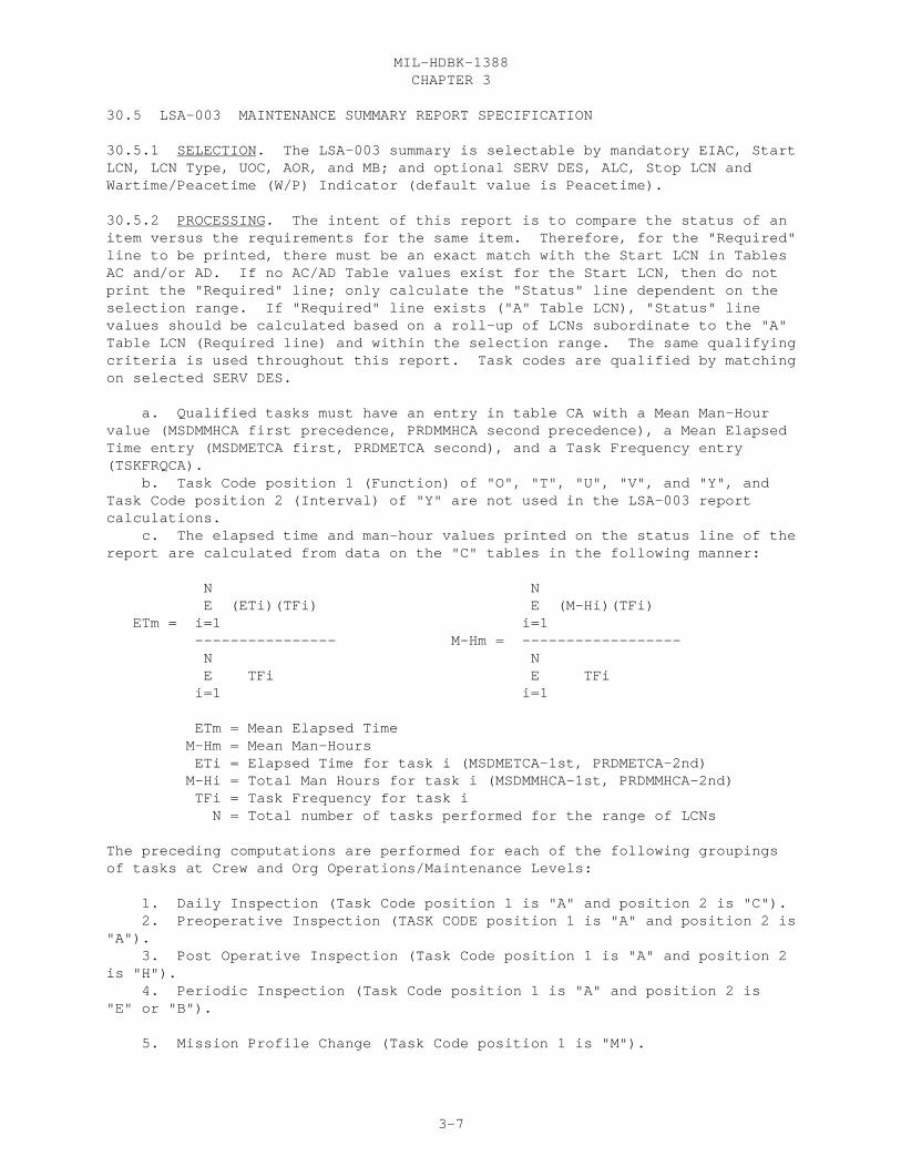
CHAPTER 3MIL-HDBK-1388
3-7
30.5 LSA-003 MAINTENANCE SUMMARY REPORT SPECIFICATION
30.5.1 SELECTION. The LSA-003 summary is selectable by mandatory EIAC, StartLCN, LCN Type, UOC, AOR, and MB; and optional SERV DES, ALC, Stop LCN andWartime/Peacetime (W/P) Indicator (default value is Peacetime).
30.5.2 PROCESSING. The intent of this report is to compare the status of anitem versus the requirements for the same item. Therefore, for the "Required"line to be printed, there must be an exact match with the Start LCN in TablesAC and/or AD. If no AC/AD Table values exist for the Start LCN, then do notprint the "Required" line; only calculate the "Status" line dependent on theselection range. If "Required" line exists ("A" Table LCN), "Status" linevalues should be calculated based on a roll-up of LCNs subordinate to the "A"Table LCN (Required line) and within the selection range. The same qualifyingcriteria is used throughout this report. Task codes are qualified by matchingon selected SERV DES.
a. Qualified tasks must have an entry in table CA with a Mean Man-Hourvalue (MSDMMHCA first precedence, PRDMMHCA second precedence), a Mean ElapsedTime entry (MSDMETCA first, PRDMETCA second), and a Task Frequency entry(TSKFRQCA). b. Task Code position 1 (Function) of "O", "T", "U", "V", and "Y", andTask Code position 2 (Interval) of "Y" are not used in the LSA-003 reportcalculations. c. The elapsed time and man-hour values printed on the status line of thereport are calculated from data on the "C" tables in the following manner:
N N E (ETi)(TFi) E (M-Hi)(TFi) ETm = i=1 i=1 ---------------- M-Hm = ------------------ N N E TFi E TFi i=1 i=1
ETm = Mean Elapsed Time M-Hm = Mean Man-Hours ETi = Elapsed Time for task i (MSDMETCA-1st, PRDMETCA-2nd) M-Hi = Total Man Hours for task i (MSDMMHCA-1st, PRDMMHCA-2nd) TFi = Task Frequency for task i N = Total number of tasks performed for the range of LCNs
The preceding computations are performed for each of the following groupingsof tasks at Crew and Org Operations/Maintenance Levels:
1. Daily Inspection (Task Code position 1 is "A" and position 2 is "C"). 2. Preoperative Inspection (TASK CODE position 1 is "A" and position 2 is"A"). 3. Post Operative Inspection (Task Code position 1 is "A" and position 2is "H"). 4. Periodic Inspection (Task Code position 1 is "A" and position 2 is"E" or "B").
5. Mission Profile Change (Task Code position 1 is "M").
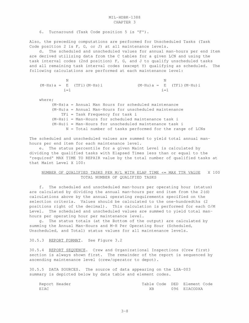
CHAPTER 3MIL-HDBK-1388
3-8
6. Turnaround (Task Code position 5 is "F").
Also, the preceding computations are performed for Unscheduled Tasks (TaskCode position 2 is F, G, or J) at all maintenance levels. d. The scheduled and unscheduled values for annual man-hours per end itemare derived utilizing data from the C tables for a given LCN and using thetask interval codes (2nd position) F, G, and J to qualify unscheduled tasksand all remaining task interval codes (except Y) qualifying as scheduled. Thefollowing calculations are performed at each maintenance level:
N N (M-Hs)a = E (TFi)(M-Hs)i (M-Hu)a = E (TFi)(M-Hu)i i=1 i=1
where; (M-Hs)a = Annual Man Hours for scheduled maintenance (M-Hu)a = Annual Man-Hours for unscheduled maintenance TFi = Task Frequency for task i (M-Hs)i = Man-Hours for scheduled maintenance task i (M-Hu)i = Man-Hours for unscheduled maintenance task i N = Total number of tasks performed for the range of LCNs
The scheduled and unscheduled values are summed to yield total annual man-hours per end item for each maintenance level. e. The status percentile for a given Maint Level is calculated bydividing the qualified tasks with Elapsed Times less than or equal to the"required" MAX TIME TO REPAIR value by the total number of qualified tasks atthat Maint Level X 100:
NUMBER OF QUALIFIED TASKS PER M/L WITH ELAP TIME <= MAX TTR VALUE X 100 TOTAL NUMBER OF QUALIFIED TASKS
f. The scheduled and unscheduled man-hours per operating hour (status)are calculated by dividing the annual man-hours per end item from the 2(d)calculations above by the annual operating requirements specified on theselection criteria. Values should be calculated to the one-hundredths (2positions right of the decimal). This calculation is performed for each O/MLevel. The scheduled and unscheduled values are summed to yield total man-hours per operating hour per maintenance level. g. The status totals (at the Bottom of the output) are calculated bysumming the Annual Man-Hours and M-H Per Operating Hour (Scheduled,Unscheduled, and Total) status values for all maintenance levels.
30.5.3 REPORT FORMAT. See Figure 3.2
30.5.4 REPORT SEQUENCE. Crew and Organizational Inspections (Crew first)section is always shown first. The remainder of the report is sequenced byascending maintenance level (crew/operator to depot).
30.5.5 DATA SOURCES. The source of data appearing on the LSA-003summary is depicted below by data table and element codes.
Report Header Table Code DED Element Code EIAC XB 096 EIACODXA

CHAPTER 3MIL-HDBK-1388
3-9
LCN NOMENCLATURE XB 201 LCNAMEXB START LCN XB 199 LSACONXB TYPE XB 209 LCNTYPXB ALC XB 019 ALTLCNXB STOP LCN XB 199 LSACONXB UOC XF 501 UOCSEIXC SERV DES CA 427 TASKCDCA AOR AG 023 ANOPREAG MB CA 238 AORMSBCA W/P AG 282 OPRQINAG CREW INSPECTIONS & ORGANIZATIONAL INSPECTIONS CA 427 TASKCDCA REQUIRED DAILY INSP M-H AD 280 DINMMHAD ELAP AD 280 DINMETAD PREOP INSP M-H AD 280 PREMMHAD ELAP AD 280 PREMETAD POSTOP INSP M-H AD 280 POIMMHAD ELAP AD 280 POIMETAD PERIODIC INSP M-H AD 280 PINMMHAD ELAP AD 280 PINMETAD MSSN PROF CHG M-H AD 280 MPCMMHAD ELAP AD 280 MPCMETAD TURNAROUND M-H AD 280 TINMMHAD ELAP AD 280 TINMETAD STATUS (CALCULATED - SEE SPEC WRITE-UP) MAINTENANCE LEVEL CA 427 TASKCDCA REQUIRED UNSCH MAINT M-H AC 498 MLUMMHAC ELAP AC 498 MLUMETAC MAX TIME TO REPAIR AC 222 MLMTTRAC PCT AC 286 MLPERCAC ANNUAL M-H PER END ITEM SCHED AC 020 MLSAMHAC UNSCHED AC 020 MLUAMHAC TOTAL (CALCULATED - SEE SPEC) M-H PER OPER HOUR SCHED AC 215 MLSMHOAC UNSCHED AC 215 MLUMHOAC TOTAL (CALCULATED - SEE SPEC) STATUS (CALCULATED - SEE SPEC)

CHAPTER 3MIL-HDBK-1388
3-10
LSA-003

CHAPTER 3MIL-HDBK-1388
3-11
30.6 LSA-004 MAINTENANCE ALLOCATION CHART REPORT SPECIFICATION
30.6.1 SELECTION. The LSA-004 report is selectable by mandatory EIAC, StartLCN, SERV DES, and Draft/Proof option; and optional ALC, Stop LCN and UOC. Other optional selections include Item Category Codes, Tool List option, TMCode, Display Option (LCN or TM FGC for the Draft MAC, Proof MAC and AviationMAC must be sequenced by TM FGC), and Technical Manual Designation (providedby requiring authority). The Draft/Proof option allows for a Draft MAC, ProofMAC, or Aviation MAC to be selected. If the Tool List option is not selected,then the ICC option cannot be used. Selectable ICCs are limited to D, G, H,M, N, P, R, V, AC, and 1-8.
30.6.2 PROCESSING. The LSA-004 is a report of the man-hour allocations bymaintenance function and maintenance level. The report can be requested aseither a draft (reflects all maintenance functions allowed in the LSAR database) or a proof (formatted in accordance with figure 20, MIL-M-63038 (TM),Manuals, Technical). The draft is printed on computer stock paper and theproof is printed on 8 1/2 by 11 inch plain bond paper. The draft MAC consistsof two parts, the man-hour allocation section and the cross-referenced toollist (if selected). The Proof MAC and Aviation MAC consist of four sections,three of which are obtainable from the LSAR. The proof tool list shouldconsist of only ICCs for peculiar or special tools and for existing or newtool sets, kits and outfits. It should not include common tools that are partof a kit as separately listed (referenced) items. CA table LCNs must existwithin the range of selected LCNs and with a qualified Task Code (Task Codesare qualified against the selected SERV DES by matching on the 4th position). If the tool option is selected, qualified CG table LCNs must have a tool/testequipment having an ICC that matches on those selected (must match theReference Number and CAGE in table CG (TSREFNCG and TSCAGECG) with theReference Number and CAGE in table EA (SEREFNEA and SECAGEEA) in order toaccess the ICC). Asterisks will be printed in the Man-Hours column of thisreport when: a. there is more than one Task Code qualified for a given O/Mlevel and Task Function and either the Man-Hour or Task Frequency is blank orzero; or b. when there is qualified Task Code for a given O/M level and TaskFunction, but there is no Man-Hour value, whatsoever.
a. Task Functions (1st position Task Code) for the draft will appear asthey do in the LSAR data base.
b. Task Functions not allowed on the Proof MAC will be automaticallyincluded as follows:
1. Access, Disassemble/Assemble and Fault Locate Times are includedas part of Repair time. 2. End-of-Runway Inspection times are included as part of the Inspecttime. 3. Remove and Install times are included as part of theRemove/Install time. 4. Remove and Replace times are included as Replace time. 5. Lubricate times are included as part of the Service times. 6. Clean, Mission Profile Change, Package/Unpackage, Preserve,Operate, Transport, and Transportation Preparation are not included on theMAC. Also, Battle Damage Assessment Repair (BDAR) tasks are not included onthe MAC (these are identified by a Task Interval Code (2nd position) of "Y").

CHAPTER 3MIL-HDBK-1388
3-12
b. Operations/Maintenance (O/M) Level "G" is not included on the ProofMAC and O/M level "L" is included as part of O/M level "H" on the Proof. AllO/M levels are included on the Draft MAC (C, O, F, H, G, L, D). Only O/Mlevels of "O", "F", and "D" apply when the aviation MAC is developed.Maintenance category AVUM equates to "O", AVIM to "F", and Depot to "D".
c. For each O/M level, the Mean Man-Hours is calculated for all taskswith the same Task Function as follows:
N E (TFi)(M-Hi) i=1 M-Hm = ---------------------- N E TFi i=1
M-Hm = Mean Man-Hours M-Hi = Total Man-Hours for task i (calculated by summing the Man-Hours for each Person ID of task i) TFi = Task Frequency for task i N = Total number of tasks performed
Man-Hours are rounded to the nearest tenth of an hour.
d. For a given component/assembly (LCN driven)/Maintenance Functioncombination, a new line is required for each applicable maintenance level.This will enable necessary tools to be linked to specific maintenance levels.
e. Section III, Tool and Test Equipment Requirements, consists of toolsand test equipment required to perform the maintenance functions listed inSection II, Maintenance Allocation Summary. Sections II and III are crossindexed by the "Tool or Test Equipment Reference Code" which is generatedbased on the ascending Reference Number sequence in Section III.
f. Section IV, Remarks, is based upon Remarks entered against qualifiedMAC tasks. Section II and IV are cross indexed by the Remarks Code containedin column 6 of Section II and the Reference Code in column 1 of Section IV.
30.6.3 REPORT FORMAT. See Figure 3.3
30.6.4 REPORT SEQUENCE. Section II is sequenced by ascending LCN or TM FGCdepending on the Display Option selected, then by ascending maintenancefunction based on the 1st position of the Task Code. Section III is sequencedby ascending Reference Numbers and CAGE codes. Section IV is sequenced byascending Remarks Reference Code.
30.6.5 DATA SOURCES. The source of data appearing on the LSA-004summary is depicted below by data table and element codes.
Report Header Table Code DED Element Code EIAC XB 096 EIACODXA LCN NOMENCLATURE XB 201 LCNAMEXB
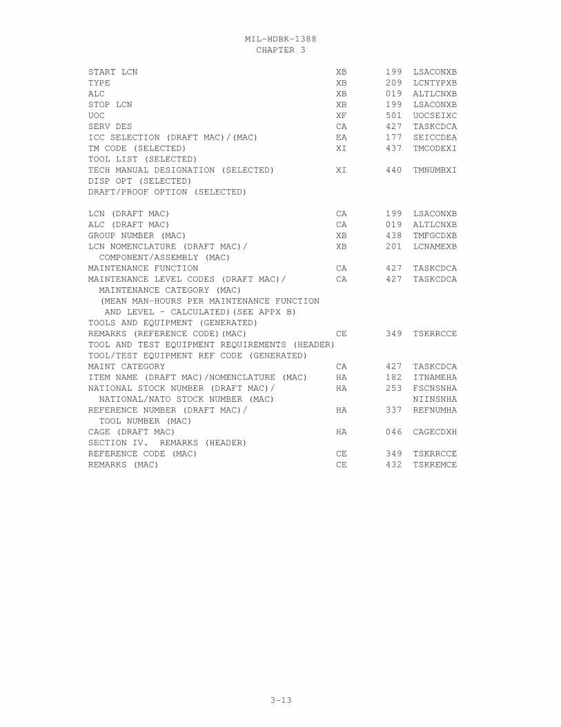
CHAPTER 3MIL-HDBK-1388
3-13
START LCN XB 199 LSACONXB TYPE XB 209 LCNTYPXB ALC XB 019 ALTLCNXB STOP LCN XB 199 LSACONXB UOC XF 501 UOCSEIXC SERV DES CA 427 TASKCDCA ICC SELECTION (DRAFT MAC)/(MAC) EA 177 SEICCDEA TM CODE (SELECTED) XI 437 TMCODEXI TOOL LIST (SELECTED) TECH MANUAL DESIGNATION (SELECTED) XI 440 TMNUMBXI DISP OPT (SELECTED) DRAFT/PROOF OPTION (SELECTED)
LCN (DRAFT MAC) CA 199 LSACONXB ALC (DRAFT MAC) CA 019 ALTLCNXB GROUP NUMBER (MAC) XB 438 TMFGCDXB LCN NOMENCLATURE (DRAFT MAC)/ XB 201 LCNAMEXB COMPONENT/ASSEMBLY (MAC) MAINTENANCE FUNCTION CA 427 TASKCDCA MAINTENANCE LEVEL CODES (DRAFT MAC)/ CA 427 TASKCDCA MAINTENANCE CATEGORY (MAC) (MEAN MAN-HOURS PER MAINTENANCE FUNCTION AND LEVEL - CALCULATED)(SEE APPX B) TOOLS AND EQUIPMENT (GENERATED) REMARKS (REFERENCE CODE)(MAC) CE 349 TSKRRCCE TOOL AND TEST EQUIPMENT REQUIREMENTS (HEADER) TOOL/TEST EQUIPMENT REF CODE (GENERATED) MAINT CATEGORY CA 427 TASKCDCA ITEM NAME (DRAFT MAC)/NOMENCLATURE (MAC) HA 182 ITNAMEHA NATIONAL STOCK NUMBER (DRAFT MAC)/ HA 253 FSCNSNHA NATIONAL/NATO STOCK NUMBER (MAC) NIINSNHA REFERENCE NUMBER (DRAFT MAC)/ HA 337 REFNUMHA TOOL NUMBER (MAC) CAGE (DRAFT MAC) HA 046 CAGECDXH SECTION IV. REMARKS (HEADER) REFERENCE CODE (MAC) CE 349 TSKRRCCE REMARKS (MAC) CE 432 TSKREMCE

CHAPTER 3MIL-HDBK-1388
3-14
LSA-004

CHAPTER 3MIL-HDBK-1388
3-15

CHAPTER 3MIL-HDBK-1388
3-16

CHAPTER 3MIL-HDBK-1388
3-17

CHAPTER 3MIL-HDBK-1388
3-18

CHAPTER 3MIL-HDBK-1388
3-19
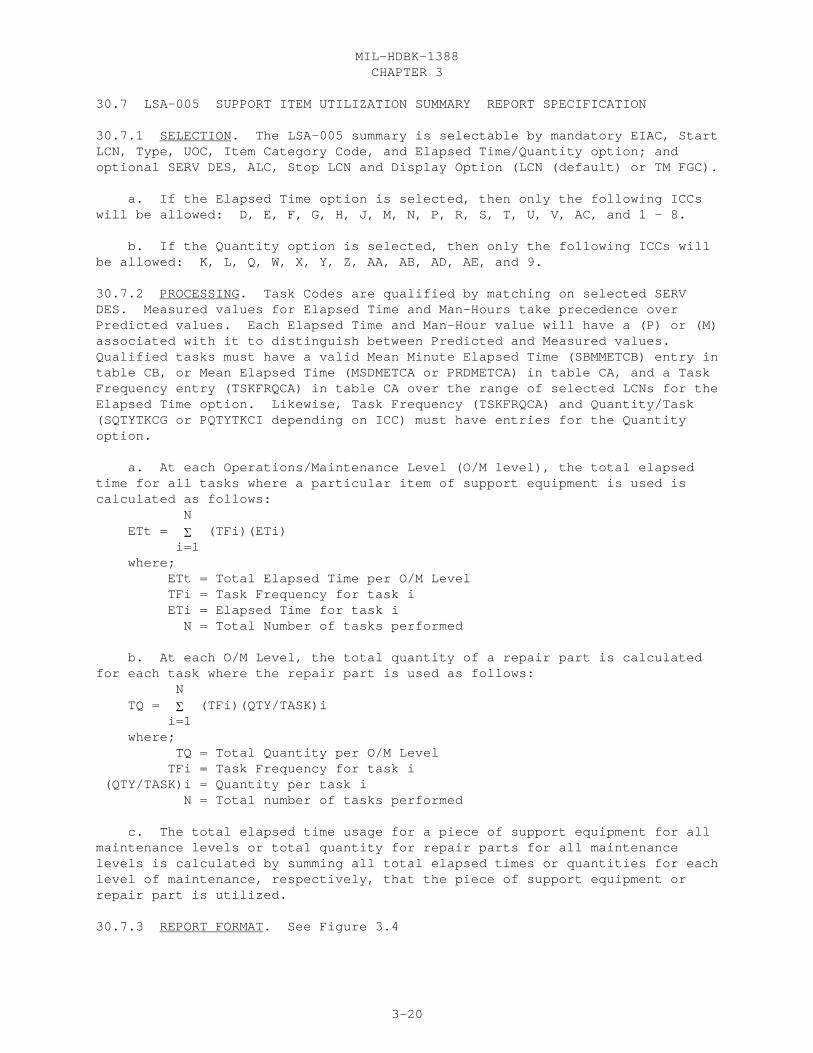
CHAPTER 3MIL-HDBK-1388
3-20
30.7 LSA-005 SUPPORT ITEM UTILIZATION SUMMARY REPORT SPECIFICATION
30.7.1 SELECTION. The LSA-005 summary is selectable by mandatory EIAC, StartLCN, Type, UOC, Item Category Code, and Elapsed Time/Quantity option; andoptional SERV DES, ALC, Stop LCN and Display Option (LCN (default) or TM FGC).
a. If the Elapsed Time option is selected, then only the following ICCswill be allowed: D, E, F, G, H, J, M, N, P, R, S, T, U, V, AC, and 1 - 8.
b. If the Quantity option is selected, then only the following ICCs willbe allowed: K, L, Q, W, X, Y, Z, AA, AB, AD, AE, and 9.
30.7.2 PROCESSING. Task Codes are qualified by matching on selected SERVDES. Measured values for Elapsed Time and Man-Hours take precedence overPredicted values. Each Elapsed Time and Man-Hour value will have a (P) or (M)associated with it to distinguish between Predicted and Measured values. Qualified tasks must have a valid Mean Minute Elapsed Time (SBMMETCB) entry intable CB, or Mean Elapsed Time (MSDMETCA or PRDMETCA) in table CA, and a TaskFrequency entry (TSKFRQCA) in table CA over the range of selected LCNs for theElapsed Time option. Likewise, Task Frequency (TSKFRQCA) and Quantity/Task(SQTYTKCG or PQTYTKCI depending on ICC) must have entries for the Quantityoption.
a. At each Operations/Maintenance Level (O/M level), the total elapsedtime for all tasks where a particular item of support equipment is used iscalculated as follows: N ETt = � (TFi)(ETi) i=1 where; ETt = Total Elapsed Time per O/M Level TFi = Task Frequency for task i ETi = Elapsed Time for task i N = Total Number of tasks performed
b. At each O/M Level, the total quantity of a repair part is calculatedfor each task where the repair part is used as follows: N TQ = � (TFi)(QTY/TASK)i i=1 where; TQ = Total Quantity per O/M Level TFi = Task Frequency for task i (QTY/TASK)i = Quantity per task i N = Total number of tasks performed
c. The total elapsed time usage for a piece of support equipment for allmaintenance levels or total quantity for repair parts for all maintenancelevels is calculated by summing all total elapsed times or quantities for eachlevel of maintenance, respectively, that the piece of support equipment orrepair part is utilized.
30.7.3 REPORT FORMAT. See Figure 3.4

CHAPTER 3MIL-HDBK-1388
3-21
30.7.4 REPORT SEQUENCE. The report is sequenced first by ICC (A - Z, 1 - 9);second by ascending reference number; third by ascending maintenance level(crew -depot); and fourth by ascending LCN or TM FGC.
30.7.5 DATA SOURCES. The source of data appearing on the LSA-005summary is depicted below by data table and element codes.
Report Header Table Code DED Element Code EIAC XB 096 EIACODXA LCN NOMENCLATURE XB 201 LCNAMEXB START LCN XB 199 LSACONXB LCN TYPE XB 209 LCNTYPXB ALC XB 019 ALTLCNXB STOP LCN XB 199 LSACONXB UOC XF 501 UOCSEIXC SERV DES CA 427 TASKCDCA ITEM CATEGORY CODES (T/Q OPTION = ELAPSED TIME) EA 177 SEICCDEA (T/Q OPTION = QUANTITY) HG 177 ITMCATHG T/Q OPTION (SELECTED) DISPLAY OPTION (SELECTED) SUPPORT ITEM REFERENCE NUMBER (T/Q OPTION = ELAPSED TIME) CG 337 TSREFNCG (T/Q OPTION = QUANTITY) CI 337 PROREFCI CAGE (T/Q OPTION = ELAPSED TIME) CG 046 TSCAGECG (T/Q OPTION = QUANTITY) CI 046 PROCAGCI ITEM NAME HA 182 ITNAMEHA M/L CA 427 TASKCDCA LCN CA 199 LSACONXB ALC CA 019 ALTLCNXB LCN NOMENCLATURE XB 201 LCNAMEXB TM FUNCT GROUP CODE XB 438 TMFGCDXB TASK CD CA 427 TASKCDCA TASK IDENTIFICATION CA 431 TASKIDCA TASK FREQ CA 430 TSKFRQCA MB CA 238 AORMSBCA ELAP TIME PREDICTED CA 224 PRDMETCA MEASURED CA 224 MSDMETCA MAN-HOURS PREDICTED CA 225 PRDMMHCA MEASURED CA 225 MSDMMHCA QTY/TA (T/Q OPTION = ELAPSED TIME) CG 319 SQTYTKCG (T/Q OPTION = QUANTITY) CI 319 PQTYTKCI UM (T/Q OPTION = ELAPSED TIME) CG 491 SQTKUMCG (T/Q OPTION = QUANTITY) CI 491 PQTKUMCI TOTAL ELAPSED TIME USAGE FOR SUPPORT EQUIPMENT FOR MAINTENANCE LEVEL (CALCULATED) TOTAL ELAPSED TIME USAGE FOR SUPPORT EQUIPMENT FOR ALL MAINTENANCE LEVELS (CALCULATED)

CHAPTER 3MIL-HDBK-1388
3-22
LSA-005

CHAPTER 3MIL-HDBK-1388
3-23
30.8 LSA-006 CRITICAL MAINTENANCE TASK SUMMARY REPORT SPECIFICATION
30.8.1 SELECTION. The LSA-006 summary is selectable by mandatory EIAC, StartLCN, Type, UOC, and Critical Criteria (optional between Task Frequency,Elapsed Time, Man-Hours, and Annual Man-Hours); and optional SERV DES, ALC,Stop LCN, Display Option (LCN or TM FGC), Maintenance Level, and Unscheduledor Scheduled maintenance interval.
30.8.2 PROCESSING. Task codes must qualify by matching on selected SERV DES. If unscheduled maintenance interval is selected, then task codes are furtherqualified by checking the second position for F, G, or J. If scheduledmaintenance interval is selected, then task codes are qualified by checkingthe second position for A, B, C, E, H, K, L, M, N, P, Q, or R. Task IntervalCode of Y (BDAR) is not included in the LSA-006.
a. Depending upon selection option chosen (Task Frequency, Elapsed Time,Man-Hours, and Annual Man-Hours), at least one qualifying task with a TaskFrequency, or Elapsed Time, or Mean Man-Hours must be entered for thecorresponding selection. Annual Man-Hour selection requires Elapsed Time andMean Man Hours values entered.
b. When man-hours or elapsed times are reported each value will bepreceded by a (P) or (M) to indicate to indicate predicted or measured values,respectively. Where a measured value has not been input, the report willdefault to the predicted value.
c. Annual man-hours is computed by multiplying the mean man-hours by thetask frequency for the given task.
30.8.3 REPORT FORMAT. See Figure 3.5
30.8.4 REPORT SEQUENCE. This report is sequenced by descending criticalvalue. If the critical values are identical, then the report sequences byascending LCN, then by ascending task codes (start with first position).
30.8.5 DATA SOURCES. The source of data appearing on the LSA-006summary is depicted below by data table and element codes.
Report Header Table Code DED Element Code
EIAC XB 096 EIACODXA LCN NOMENCLATURE XB 201 LCNAMEXB START LCN XB 199 LSACONXB TYPE XB 209 LCNTYPXB ALC XB 019 ALTLCNXB STOP LCN XB 199 LSACONXB UOC XF 501 UOCSEIXC SERV DES CA 427 TASKCDCA DISPLAY OPTION (SELECTED)
CRITICAL CRITERIA (HEADER) THE FOLLOWING TASKS EXCEED (SELECTED) THIS REPORT COVERS THE FOLLOWING MAINTENANCE LEVELS (SELECTED)

CHAPTER 3MIL-HDBK-1388
3-24
THIS REPORT COVERS (SELECTED) TM FGC XB 438 TMFGCDXB ALC CA 019 ALTLCNXB LCN NOMENCLATURE XB 201 LCNAMEXB REFERENCE NUMBER HG 337 REFNUMHA CAGE HG 046 CAGECDXH TASK CD CA 427 TASKCDCA TASK IDENTIFICATION CA 431 TASKIDCA TSK FREQ CA 430 TSKFRQCA MB CA 238 AORMSBCA MAN-HOURS (P) CA 225 PRDMMHCA MAN-HOURS (M) CA 225 MSDMMHCA ELAPSED TIME (P) CA 224 PRDMETCA ELAPSED TIME (M) CA 224 MSDMETCA ANNUAL MAN-HOURS (CALCULATED) LCN CA 199 LSACONXB

CHAPTER 3MIL-HDBK-1388
3-25
LSA-006

CHAPTER 3MIL-HDBK-1388
3-26
30.9 LSA-007 SUPPORT EQUIPMENT REQUIREMENTS BY SSC AND MAINTENANCE LEVELREPORT SPECIFICATION
30.9.1 SELECTION. The LSA-007 summary is selectable by mandatory EIAC, StartLCN, Type, and UOC; and optional SERV DES, ICCs, ALC, Stop LCN, SSC,Maintenance Level (M/L), Display Option (LCN (default) or TM FGC), and SEQ OPT(SSC-M/L or M/L-SSC (default)).
30.9.2 PROCESSING. Task codes are qualified by matching on selected SERV DESand M/L against the range of LCNs chosen. Selected Item Category Codes arelimited to D, G, H, M, N, P, R, V, 1-8, AC, and AF.
30.9.3 REPORT FORMAT. See Figure 3.6
30.9.4 REPORT SEQUENCE. This report is sequenced according to the selectedSEQ OPT (SSC then M/L or M/L then SSC) first, then by DISP OPT (LCN or TM FGC)second, and Reference Number third.
30.9.5 DATA SOURCES. The source of data appearing on the LSA-007summary is depicted below by data table and element codes.
Report Header Table Code DED Element Code
EIAC XB 096 EIACODXA LCN NOMENCLATURE XB 201 LCNAMEXB START LCN XB 199 LSACONXB TYPE XB 209 LCNTYPXB ALC XB 019 ALTLCNXB STOP LCN XB 199 LSACONXB UOC XF 501 UOCSEIXC SERV DES CA 427 TASKCDCA ICC (SELECTED) EA 177 SEICCDEA (NOTE: ALLOW REPORT TO PULL ONLY ITEMS WITH ICCs FROM EA TABLE) SSC CD 387 SKSPCDGA M/L CA 427 TASKCDCA SEQ OPT (SELECTED) DISP OPT (SELECTED)
ITEM NAME HA 182 ITNAMEHA REFERENCE NUMBER CG 337 TSREFNCG CAGE CG 046 TSCAGECG LCN CG 199 LSACONXB ALC CG 019 ALTLCNXB TASK CD CG 427 TASKCDCA TASK IDENTIFICATION CA 431 TASKIDCA TM FGC XB 438 TMFGCDXB

CHAPTER 3MIL-HDBK-1388
3-27
LSA-007

CHAPTER 3MIL-HDBK-1388
3-28
30.10 LSA-008 SUPPORT EQUIPMENT RQMTS BY M/L REPORT SPECIFICATION
30.10.1 SELECTION. The LSA-008 summary is selectable by mandatory EIAC,Start LCN, Type, UOC; and optional SERV DES, ALC, Stop LCN, Maintenance Level,and Item Category Code.
30.10.2 PROCESSING. As a minimum, there must be one qualified LCN (withinthe specified LCN range) with a Support Item Reference Number and CAGE enteredagainst it (table HA) that matches on selected ICCs and a Task Code thatmatches on selected Maintenance Level and SERV DES.
a. Items qualifying as "Support/Test Equipment and Tools" must have anICC of D, G, H, M, N, P, R, V, 1-8, or AC.
b. Items qualifying as "Spare and Repair Parts" must have an ICC of X, Y,Z, 9, AA, AB, or AE.
c. Items qualifying as "Other" must have an ICC of E, F, J, Q, S, T, W,AD, or AF.
30.10.3 REPORT FORMAT. See Figure 3.7
30.10.4 REPORT SEQUENCE. This report is sequenced by ascending MaintenanceLevel (crew - depot), then ascending ICC, then ascending Reference Numberwithin each ICC grouping. The ICC grouping order is Support/Test Equipmentand Tools, then Spare and Repair Parts, then Other.
30.10.5 DATA SOURCES. The source of data appearing on the LSA-008summary is depicted below by data table and element codes.
Report Header Table Code DED Element Code
EIAC XB 096 EIACODXA LCN NOMENCLATURE XB 201 LCNAMEXB START LCN XB 199 LSACONXB TYPE XB 209 LCNTYPXB ALC XB 019 ALTLCNXB STOP LCN XB 199 LSACONXB UOC XF 501 UOCSEIXC SERV DES CA 427 TASKCDCA M/L SEL (SELECTED) ICC (SELECTED)
SUPPORT/TEST EQUIPMENT AND TOOLS (HEADER) M/L CA 427 TASKCDCA ICC EA 177 SEICCDEA REFERENCE NUMBER CG 337 TSREFNCG CAGE CG 046 TSCAGECG ITEM NAME HA 182 ITNAMEHA QTY/TASK CG 319 SQTYTKCG UM CG 491 SQTKUMCG SUPPORT LCN CG 199 LSACONXB ALC CG 019 ALTLCNXB TASK CD CG 427 TASKCDCA

CHAPTER 3MIL-HDBK-1388
3-29
TASK FREQ CA 430 TSKFRQCA MB CA 238 AORMSBCA SSC CD 387 SKSPCDGA HMPC CA 155 HAZMPCCA SPARES AND REPAIR PARTS (HEADER) M/L CI 427 TSKTCDCI ICC HG 177 ITMCATHG REFERENCE NUMBER CI 337 PROREFCI CAGE CI 046 PROCAGCI ITEM NAME HA 182 ITNAMEHA QTY/TASK CI 319 PQTYTKCI UM CI 491 PQTKUMCI SUPPORT LCN CI 199 TSKLCNCI ALC CI 019 TSKALCCI TASK CD CI 427 TSKTCDCI TASK FREQ CA 430 TSKFRQCA MB CA 238 AORMSBCA SSC CD 387 SKSPCDGA HMPC CA 155 HAZMPCCA
OTHER (HEADER) M/L CI 427 TSKTCDCI ICC EA/HG 177 ITMCATHG REFERENCE NUMBER CI 337 PROREFCI CAGE CI 046 PROCAGCI ITEM NAME HA 182 ITNAMEHA QTY/TASK CI 319 PQTYTKCI UM CI 491 PQTKUMCI SUPPORT LCN CI 199 TSKLCNCI ALC CI 019 TSKALCCI TASK CD CI 427 TSKTCDCI TASK FREQ CA 430 TSKFRQCA MB CA 238 AORMSBCA SSC CD 387 SKSPCDGA HMPC CA 155 HAZMPCCA

CHAPTER 3MIL-HDBK-1388
3-30
LSA-008

CHAPTER 3MIL-HDBK-1388
3-31
30.11 LSA-009 SUPPORT ITEMS VALIDATION REPORT SPECIFICATION
30.11.1 SELECTION. The LSA-009 summary is selected by a mandatory EIAC,START LCN and at least one selection of Item Category Code (ICC) (table HA) orProvisioning Technical Documentation Selection Code (PTD SELECT) (table HG). Optional selections are ALC, STOP LCN, SEQUENCE and UOC. The LCN-TYPE (TYPE)is always "P". If both PTD SELECT and ICC are selected, then to qualify anitem, it must match BOTH selected codes or code combinations.
30.11.2 PROCESSING. At least one qualified item by either PTD SELECT or ICCmust be contained in the selected range of LCNs in order to produce an LSA-009summary. The UM-PRICE with a "Y" PUC (PROUMPHE) is displayed on the summary.
30.11.3 REPORT FORMAT. See Figure 3.8
30.11.4 REPORT SEQUENCE. The report is sequenced in either ascendingReference Number and CAGE, or LCN. If left blank, sequencing is by ReferenceNumber and CAGE.
NOTE: An optional sort outside the validation requirements is by ascendingPCCN/PLISN.
30.11.5 DATA SOURCES. The source of data appearing on the LSA-009summary is depicted below by data table and element codes.
Report header Table Code DED Element Code
EIAC HG 096 EIACODXA ITEM NAME HA 182 ITNAMEHA START LCN HG 199 LSACONXB ALC HG 019 ALTLCNXB STOP LCN HG 199 LSACONXB UOC HO/XC 501 UOCSEIXC SEQUENCE (SELECTED) ITEM CATEGORY CODES SELECTED: HG 177 ITMCATHG PTD LISTS SELECTED PPL HG 313 PPLPTDHG SFPPL HG 313 SFPPTDHG LLTIL HG 313 LLIPTDHG RIL HG 313 RILPTDHG ISIL HG 313 ISLPTDHG TTEL HG 313 TTLPTDHG CBIL HG 313 CBLPTDHG PCL HG 313 PCLPTDHG SCPL HG 313 SCPPTDHG ARA HG 313 ARAPTDHG ARB HG 313 ARBPTDHG
CAGE HG 046 CAGECDXH REFERENCE NUMBER HG 337 REFNUMHA LCN HG 199 LSACONXB ALC HG 019 ALTLCNXB WUC HG 516 WRKUCDHG PCCN XC 307 PCCNUMXC

CHAPTER 3MIL-HDBK-1388
3-32
PLISN HG 309 PLISNOHG XC 309 PLISNOXC IND CD HG 162 INDCODHG ITEM NAME HA 182 ITNAMEHA NAT STOCK NUMBER (HEADER) NSN COGNIZANCE CODE HA 253 COGNSNHA NSN MATERIEL CONTROL CODE HA 253 MATNSNHA NSN FEDERAL SUPPLY CLASSIFICATION HA 253 FSCNSNHA NSN NATIONAL ITEM IDENTIFICATION NUMBER HA 253 NIINSNHA NSN SPECIAL MATERIAL IDENTIFICATION CODE/ HA 253 SMMNSNHA MATERIEL MANAGEMENT AGGREGATION CODE NSN ACTIVITY CODE HA 253 ACTNSNHA SMCC HA 395 SPMACCHA SMIC HA 392 SMAINCHA ICC HG 177 ITMCATHG UM HA 491 UNITMSHA PLT HA 299 PRDLDTHA QTY/EI HG 317 QTYPEIHG XC 317 QTYPEIXC
UM PRICE HE 492 UMPRICHE PS/PC HA 291 PHYSECHA QTY/ASY HG 316 QTYASYHG XC 316 QTYASYXC SMR HG 389 SMRCODHG SL HA 377 SHLIFEHA

CHAPTER 3MIL-HDBK-1388
3-33
LSA-009

CHAPTER 3MIL-HDBK-1388
3-34
30.12 LSA-010 PARTS STANDARDIZATION SUMMARY REPORT SPECIFICATION
30.12.1 SELECTION. The LSA-010 summary is selected by mandatory LCN, andoptional ALC, STOP LCN, UOC, AMC, CTIC1, and CTIC2. CTIC1 applies to thefirst position of the CTIC code and CTIC2 to the second position. A maximumof 4 AMCs can be selected. Default values for CTIC and AMC selections are"All" legitimate values.
30.12.2 PROCESSING. In order to produce an LSA-010 summary at least one rowof information (table HG) qualified by specified CTICs or AMC must be containedwithin the selected LCN range. All UM Prices for a given LCN/ALC combinationwill be printed out and the corresponding Lot Quantity From and To values.
30.12.3 REPORT FORMAT. See Figure 3.9
30.12.4 REPORT SEQUENCE. The report is sequenced in ascending ReferenceNumber and CAGE, CTIC1, CTIC2, or AMC as specified in the display option.
30.12.5 DATA SOURCE. The source of data appearing on the LSA-010 summary isdepicted below by data table and element codes. Report header Table Code DED Element Code EIAC HG 096 EIACODXA ITEM NAME HA 182 ITNAMEHA START LCN HG 199 LSACONXB ALC HG 019 ALTLCNXB TYPE HG 203 LCNTYPXB STOP LCN HG 199 LSACONXB UOC HO/XC 501 UOCSEIXC CTIC1 HA 058 CTICODHA CTIC2 HA 058 CTICODHA AMC HA 003 ACQMETHA DISPLAY OPTION (SELECTION) REFERENCE NO/CAGE, CTIC(S), AMC(S) CAGE HG 046 CAGECDXH REFERENCE NUMBER HG 337 REFNUMHA RNCC HA 338 REFNCCHA RNVC HA 339 REFNVCHA ITEM NAME HA 182 ITNAMEHA FSC HA 260 FSCNSNHA DAC HA 086 DOCAVCHA AMC HA 003 ACQMETHA AMSC HA 004 AMSUFCHA PPSL HA 302 PPSLSTHA CTIC1 HA 058 CTICODHA CTIC CAGE HC 046 CTCAGEHC UM PRICE HE 492 UMPRICHE LOT QUANTITY FROM HE 205 LOTQFMHE LOT QUANTITY TO HE 205 LOTQTOHE UM HA 497 UNITMSHA FY HE 145 FISCYRHE CPC HE 051 CURPRCHE TUC HE 485 TUMPRCHE PUC HE 321 PROUMPHE

CHAPTER 3MIL-HDBK-1388
3-35
LSA-010
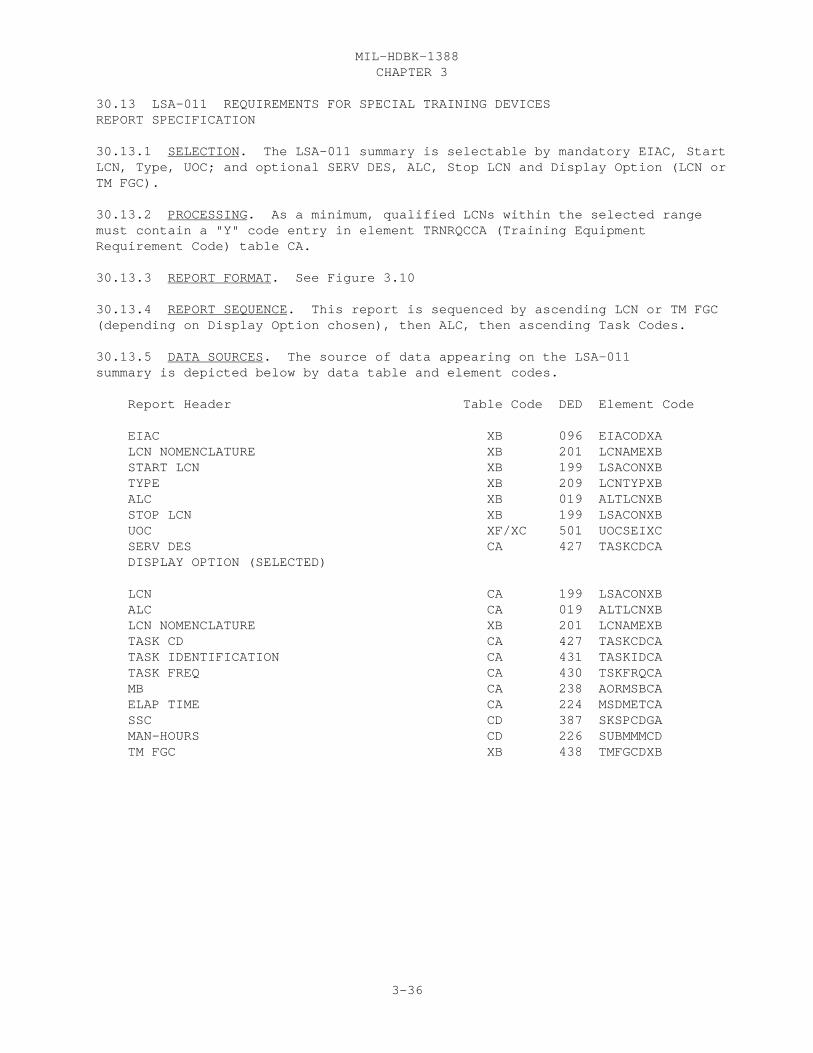
CHAPTER 3MIL-HDBK-1388
3-36
30.13 LSA-011 REQUIREMENTS FOR SPECIAL TRAINING DEVICES REPORT SPECIFICATION
30.13.1 SELECTION. The LSA-011 summary is selectable by mandatory EIAC, StartLCN, Type, UOC; and optional SERV DES, ALC, Stop LCN and Display Option (LCN orTM FGC).
30.13.2 PROCESSING. As a minimum, qualified LCNs within the selected rangemust contain a "Y" code entry in element TRNRQCCA (Training EquipmentRequirement Code) table CA.
30.13.3 REPORT FORMAT. See Figure 3.10
30.13.4 REPORT SEQUENCE. This report is sequenced by ascending LCN or TM FGC(depending on Display Option chosen), then ALC, then ascending Task Codes.
30.13.5 DATA SOURCES. The source of data appearing on the LSA-011summary is depicted below by data table and element codes.
Report Header Table Code DED Element Code
EIAC XB 096 EIACODXA LCN NOMENCLATURE XB 201 LCNAMEXB START LCN XB 199 LSACONXB TYPE XB 209 LCNTYPXB ALC XB 019 ALTLCNXB STOP LCN XB 199 LSACONXB UOC XF/XC 501 UOCSEIXC SERV DES CA 427 TASKCDCA DISPLAY OPTION (SELECTED)
LCN CA 199 LSACONXB ALC CA 019 ALTLCNXB LCN NOMENCLATURE XB 201 LCNAMEXB TASK CD CA 427 TASKCDCA TASK IDENTIFICATION CA 431 TASKIDCA TASK FREQ CA 430 TSKFRQCA MB CA 238 AORMSBCA ELAP TIME CA 224 MSDMETCA SSC CD 387 SKSPCDGA MAN-HOURS CD 226 SUBMMMCD TM FGC XB 438 TMFGCDXB

CHAPTER 3MIL-HDBK-1388
3-37
LSA-011
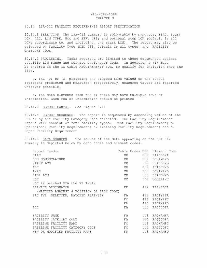
CHAPTER 3MIL-HDBK-1388
3-38
30.14 LSA-012 FACILITY REQUIREMENTS REPORT SPECIFICATION
30.14.1 SELECTION. The LSA-012 summary is selectable by mandatory EIAC, StartLCN, ALC, LCN TYPE, UOC and SERV DES; and optional Stop LCN (default is allLCNs subordinate to, and including, the start LCN). The report may also beselected by Facility Type (DED 483, Default is all types) and FACILITYCATEGORY CODE.
30.14.2 PROCESSING. Tasks reported are limited to those documented againstspecific LCN range and Service Designator Code. In addition a (Y) mustbe entered in the CA table REQUIREMENTS FOR, to qualify for inclusion into thelist.
a. The (P) or (M) preceding the elapsed time values on the outputrepresent predicted and measured, respectively. Measured values are reportedwherever possible.
b. The data elements from the EI table may have multiple rows ofinformation. Each row of information should be printed 30.14.3 REPORT FORMAT. See Figure 3.11
30.14.4 REPORT SEQUENCE. The report is sequenced by ascending values of theLCN or by the Facility Category Code selected. The Facility Requirementsreport will consist of four facility types. Test Facility Requirement; b.Operational Facility Requirement; c. Training Facility Requirement; and d.Depot Facility Requirement
30.14.5 DATA SOURCES. The source of the data appearing on the LSA-012summary is depicted below by data table and element codes.
Report Header Table Codes DED Element Code EIAC XB 096 EIACODXA LCN NOMENCLATURE XB 201 LCNAMEXB START LCN XB 199 LSACONXB ALC XB 019 ALTLCNXB TYPE XB 203 LCNTYPXB STOP LCN XB 199 LSACONXB UOC XC 501 UOCSEIXC UOC is matched VIA the XF Table SERVICE DESIGNATOR FE 427 TASKCDCA (MATCHED AGAINST 4 POSITION OF TASK CODE) FAC TYP (SELECTED, MATCHED AGAINST) FA 483 FACTYPFA FC 483 FACTYPFC FD 483 FACTYPFD FCC FA 115 FACCCDFA
FACILITY NAME FA 118 FACNAMFA FACILITY CATEGORY CODE FA 115 FACCCDFA BASELINE FACILITY NAME FC 118 FACNAMFC BASELINE FACILITY CATEGORY CODE FC 115 FACCCDFC NEW OR MODIFIED FACILITY NAME FD 118 FACNAMFD
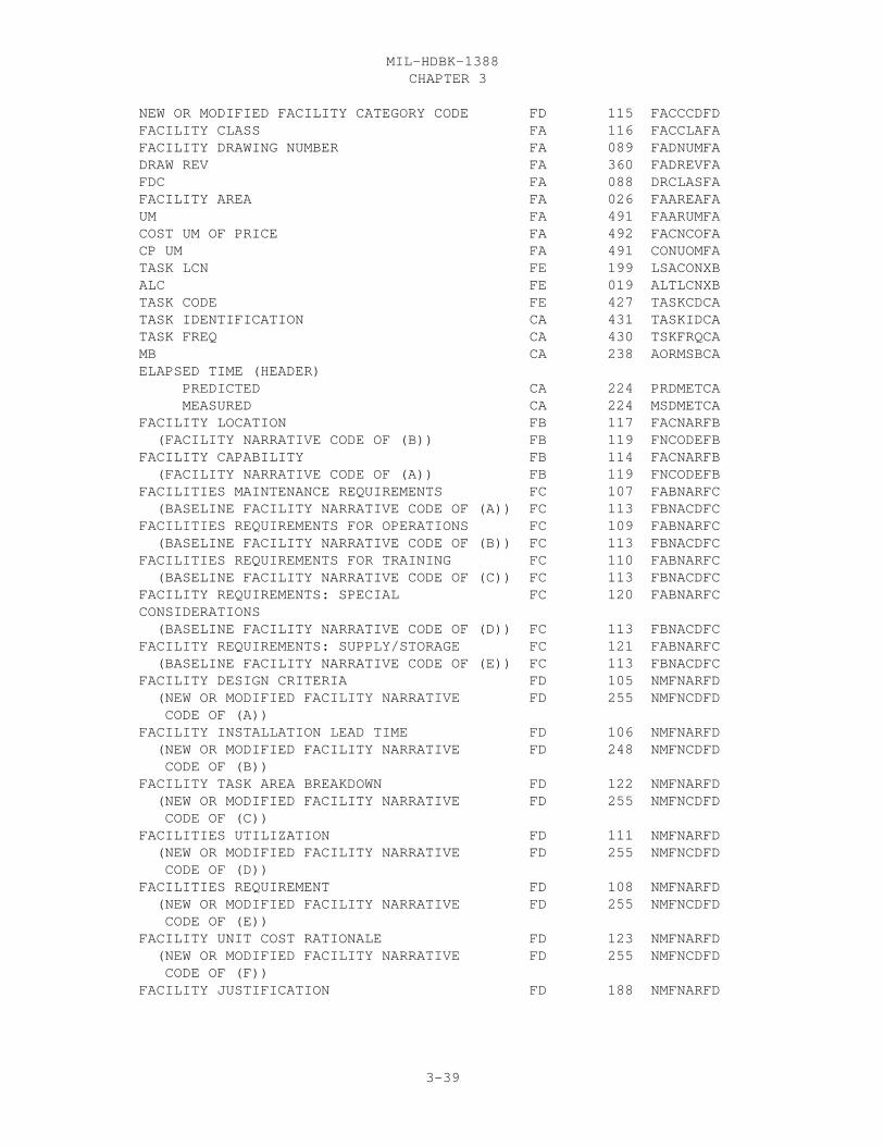
CHAPTER 3MIL-HDBK-1388
3-39
NEW OR MODIFIED FACILITY CATEGORY CODE FD 115 FACCCDFD FACILITY CLASS FA 116 FACCLAFA FACILITY DRAWING NUMBER FA 089 FADNUMFA DRAW REV FA 360 FADREVFA FDC FA 088 DRCLASFA FACILITY AREA FA 026 FAAREAFA UM FA 491 FAARUMFA COST UM OF PRICE FA 492 FACNCOFA CP UM FA 491 CONUOMFA TASK LCN FE 199 LSACONXB ALC FE 019 ALTLCNXB TASK CODE FE 427 TASKCDCA TASK IDENTIFICATION CA 431 TASKIDCA TASK FREQ CA 430 TSKFRQCA MB CA 238 AORMSBCA ELAPSED TIME (HEADER) PREDICTED CA 224 PRDMETCA MEASURED CA 224 MSDMETCA FACILITY LOCATION FB 117 FACNARFB (FACILITY NARRATIVE CODE OF (B)) FB 119 FNCODEFB FACILITY CAPABILITY FB 114 FACNARFB (FACILITY NARRATIVE CODE OF (A)) FB 119 FNCODEFB FACILITIES MAINTENANCE REQUIREMENTS FC 107 FABNARFC (BASELINE FACILITY NARRATIVE CODE OF (A)) FC 113 FBNACDFC FACILITIES REQUIREMENTS FOR OPERATIONS FC 109 FABNARFC (BASELINE FACILITY NARRATIVE CODE OF (B)) FC 113 FBNACDFC FACILITIES REQUIREMENTS FOR TRAINING FC 110 FABNARFC (BASELINE FACILITY NARRATIVE CODE OF (C)) FC 113 FBNACDFC FACILITY REQUIREMENTS: SPECIAL FC 120 FABNARFC CONSIDERATIONS (BASELINE FACILITY NARRATIVE CODE OF (D)) FC 113 FBNACDFC FACILITY REQUIREMENTS: SUPPLY/STORAGE FC 121 FABNARFC (BASELINE FACILITY NARRATIVE CODE OF (E)) FC 113 FBNACDFC FACILITY DESIGN CRITERIA FD 105 NMFNARFD (NEW OR MODIFIED FACILITY NARRATIVE FD 255 NMFNCDFD CODE OF (A)) FACILITY INSTALLATION LEAD TIME FD 106 NMFNARFD (NEW OR MODIFIED FACILITY NARRATIVE FD 248 NMFNCDFD CODE OF (B)) FACILITY TASK AREA BREAKDOWN FD 122 NMFNARFD (NEW OR MODIFIED FACILITY NARRATIVE FD 255 NMFNCDFD CODE OF (C)) FACILITIES UTILIZATION FD 111 NMFNARFD (NEW OR MODIFIED FACILITY NARRATIVE FD 255 NMFNCDFD CODE OF (D)) FACILITIES REQUIREMENT FD 108 NMFNARFD (NEW OR MODIFIED FACILITY NARRATIVE FD 255 NMFNCDFD CODE OF (E)) FACILITY UNIT COST RATIONALE FD 123 NMFNARFD (NEW OR MODIFIED FACILITY NARRATIVE FD 255 NMFNCDFD CODE OF (F)) FACILITY JUSTIFICATION FD 188 NMFNARFD

CHAPTER 3MIL-HDBK-1388
3-40
(NEW OR MODIFIED FACILITY NARRATIVE FD 255 NMFNCDFD CODE OF (G)) TYPE OF CONSTRUCTION FD 482 NMFNARFD (NEW OR MODIFIED FACILITY NARRATIVE FD 255 NMFNCDFD CODE OF (H)) UTILITIES REQUIREMENT FD 502 NMFNARFD (NEW OR MODIFIED FACILITY NARRATIVE FD 255 NMFNCDFD CODE OF (I))SUPPORT EQUIPMENT (HEADER) ITEM NAME HA 182 ITNAMEHA NSN (HEADER) FSC HA 253 FSCNSNHA NIIN HA 253 NIINSNHA REFERENCE NUMBER EA 337 SEREFNEA CAGE EA 046 SECAGEEA LENGTH EA 268 OPLENGEA WIDTH EA 268 OPWIDTEA HEIGHT EA 268 OPRHGTEA UM EA 491 LWHOUMEA WEIGHT EA 270 OPRWGTEA UM EA 491 WGTOUMEA QTY CG 319 SQTYTKCG UM CG 491 SQTKUMCG AC/DC EI 168 IPACDCEI IPS FRMAX EI 168 IPFRMXEI IPS FRMIN EI 168 IPRGMXEI IPS ORMAX EI 168 IPSRGMEI IPS OPMIN EI 168 IPOPRGEI IPS PER MAX RIPPLE EI 168 IPMXRPEI PHASE EI 168 IPPHASEI WATTS EI 168 IPPOWREI

CHAPTER 3MIL-HDBK-1388
3-41
LSA-012

CHAPTER 3MIL-HDBK-1388
3-42

CHAPTER 3MIL-HDBK-1388
3-43
30.15 LSA-013 SUPPORT EQUIPMENT GROUPING UTILIZATION SUMMARY REPORTSPECIFICATION
30.15.1 SELECTION. The LSA-013 summary is selectable by mandatory EIAC, StartLCN, Type, UOC; and optional SERV DES, ALC, Stop LCN, SE Group Number,Maintenance Level (M/L), and Display Option (LCN or TM FGC).
30.15.2 PROCESSING. Task Codes are qualified against the selected SERV DES. a. As a minimum, there must be one LCN within the selected range thatrequires a piece of support equipment (identified by Reference Number andCAGE) (match table CG with table EA) which has a valid SE GroupingIdentification Number (element SEGRCDEA) that matches the selection criteria. b. When man-hours or elapsed times are reported each value will bepreceded by a (P) or (M) to indicate predicted or measured values,respectively. Where a measured value has not been input, the report willdefault to the predicted value.
30.15.3 REPORT FORMAT. See Figure 3.12
30.15.4 REPORT SEQUENCE. This report is sequenced by ascending SE GroupNumbers and within each SE Group Number by ascending M/L, then ascending LCN,then ascending Task Code.
30.15.5 DATA SOURCES. The source of data appearing on the LSA-013summary is depicted below by data table and element codes. Report Header Table Code DED Element Code EIAC XB 096 EIACODXA LCN NOMENCLATURE XB 201 LCNAMEXB START LCN XB 199 LSACONXB TYPE XB 209 LCNTYPXB ALC XB 019 ALTLCNXB STOP LCN XB 199 LSACONXB UOC XF/XC 501 UOCSEIXC SERV DES CA 427 TASKCDCA SE GROUP NO (SELECTED) EA 421 SEGRCDEA M/L (SELECTED) CA 427 TASKCDCA DISP OPT (SELECTED) SUPPORT EQUIPMENT GROUPING IDENTIFICATION EA 413 SEGRCDEA M/L CG 427 TASKCDCA LCN CG 199 LSACONXB (NEED QUALIFYING REF NO’S AND CAGES FROM EA TABLE BASED ON SE GROUP NO) [SUPPORT EQUIPMENT REFERENCE NUMBER] EA 337 SEREFNEA [SE CAGE CODE] EA 046 SECAGEEA ALC CG 019 ALTLCNXB LCN NOMENCLATURE XB 201 LCNAMEXB TASK CD CG 427 TASKCDCA TASK IDENTIFICATION CA 431 TASKIDCA TASK FREQ CA 430 TSKFRQCA MB CA 238 AORMSBCA ELAP TIME (M) CA 224 MSDMETCA ELAP TIME (P) CA 224 PRDMETCA MAN-HOURS (M) CA 225 MSDMMHCA MAN-HOURS (P) CA 225 PRDMMHCA TM FGC XB 438 TMFGCDXB

CHAPTER 3MIL-HDBK-1388
3-44
LSA-013
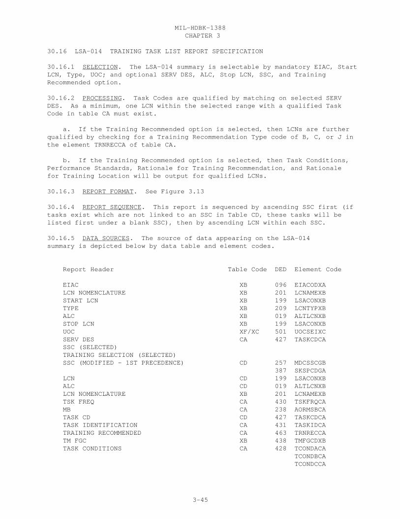
CHAPTER 3MIL-HDBK-1388
3-45
30.16 LSA-014 TRAINING TASK LIST REPORT SPECIFICATION
30.16.1 SELECTION. The LSA-014 summary is selectable by mandatory EIAC, StartLCN, Type, UOC; and optional SERV DES, ALC, Stop LCN, SSC, and TrainingRecommended option.
30.16.2 PROCESSING. Task Codes are qualified by matching on selected SERVDES. As a minimum, one LCN within the selected range with a qualified TaskCode in table CA must exist.
a. If the Training Recommended option is selected, then LCNs are furtherqualified by checking for a Training Recommendation Type code of B, C, or J inthe element TRNRECCA of table CA.
b. If the Training Recommended option is selected, then Task Conditions,Performance Standards, Rationale for Training Recommendation, and Rationalefor Training Location will be output for qualified LCNs.
30.16.3 REPORT FORMAT. See Figure 3.13
30.16.4 REPORT SEQUENCE. This report is sequenced by ascending SSC first (iftasks exist which are not linked to an SSC in Table CD, these tasks will belisted first under a blank SSC), then by ascending LCN within each SSC.
30.16.5 DATA SOURCES. The source of data appearing on the LSA-014summary is depicted below by data table and element codes.
Report Header Table Code DED Element Code
EIAC XB 096 EIACODXA LCN NOMENCLATURE XB 201 LCNAMEXB START LCN XB 199 LSACONXB TYPE XB 209 LCNTYPXB ALC XB 019 ALTLCNXB STOP LCN XB 199 LSACONXB UOC XF/XC 501 UOCSEIXC SERV DES CA 427 TASKCDCA SSC (SELECTED) TRAINING SELECTION (SELECTED) SSC (MODIFIED - 1ST PRECEDENCE) CD 257 MDCSSCGB 387 SKSPCDGA LCN CD 199 LSACONXB ALC CD 019 ALTLCNXB LCN NOMENCLATURE XB 201 LCNAMEXB TSK FREQ CA 430 TSKFRQCA MB CA 238 AORMSBCA TASK CD CD 427 TASKCDCA TASK IDENTIFICATION CA 431 TASKIDCA TRAINING RECOMMENDED CA 463 TRNRECCA TM FGC XB 438 TMFGCDXB TASK CONDITIONS CA 428 TCONDACA TCONDBCA TCONDCCA

CHAPTER 3MIL-HDBK-1388
3-46
PERFORMANCE STANDARDS CA 287 PRSTDACA PRSTDBCA PRSTDCCA RATIONALE FOR TRAINING RECOMMENDATION CA 462 TRNRATCA RATIONALE FOR TRAINING LOCATION CA 461 TRNLOCCA

CHAPTER 3MIL-HDBK-1388
3-47
LSA-014
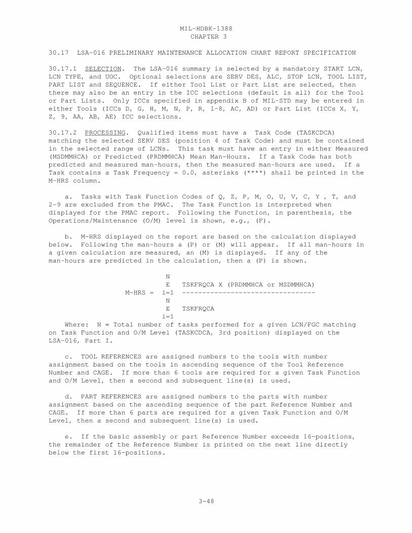
CHAPTER 3MIL-HDBK-1388
3-48
30.17 LSA-016 PRELIMINARY MAINTENANCE ALLOCATION CHART REPORT SPECIFICATION
30.17.1 SELECTION. The LSA-016 summary is selected by a mandatory START LCN,LCN TYPE, and UOC. Optional selections are SERV DES, ALC, STOP LCN, TOOL LIST,PART LIST and SEQUENCE. If either Tool List or Part List are selected, thenthere may also be an entry in the ICC selections (default is all) for the Toolor Part Lists. Only ICCs specified in appendix B of MIL-STD may be entered ineither Tools (ICCs D, G, H, M, N, P, R, 1-8, AC, AD) or Part List (ICCs X, Y,Z, 9, AA, AB, AE) ICC selections.
30.17.2 PROCESSING. Qualified items must have a Task Code (TASKCDCA)matching the selected SERV DES (position 4 of Task Code) and must be containedin the selected range of LCNs. This task must have an entry in either Measured(MSDMMHCA) or Predicted (PRDMMHCA) Mean Man-Hours. If a Task Code has bothpredicted and measured man-hours, then the measured man-hours are used. If aTask contains a Task Frequency = 0.0, asterisks (****) shall be printed in theM-HRS column.
a. Tasks with Task Function Codes of Q, Z, P, M, O, U, V, C, Y , T, and 2-9 are excluded from the PMAC. The Task Function is interpreted whendisplayed for the PMAC report. Following the Function, in parenthesis, theOperations/Maintenance (O/M) level is shown, e.g., (F).
b. M-HRS displayed on the report are based on the calculation displayedbelow. Following the man-hours a (P) or (M) will appear. If all man-hours ina given calculation are measured, an (M) is displayed. If any of theman-hours are predicted in the calculation, then a (P) is shown.
N E TSKFRQCA X (PRDMMHCA or MSDMMHCA) M-HRS = i=1 --------------------------------- N E TSKFRQCA i=1 Where: N = Total number of tasks performed for a given LCN/FGC matchingon Task Function and O/M Level (TASKCDCA, 3rd position) displayed on theLSA-016, Part I.
c. TOOL REFERENCES are assigned numbers to the tools with numberassignment based on the tools in ascending sequence of the Tool ReferenceNumber and CAGE. If more than 6 tools are required for a given Task Functionand O/M Level, then a second and subsequent line(s) is used.
d. PART REFERENCES are assigned numbers to the parts with numberassignment based on the ascending sequence of the part Reference Number andCAGE. If more than 6 parts are required for a given Task Function and O/MLevel, then a second and subsequent line(s) is used.
e. If the basic assembly or part Reference Number exceeds 16-positions,the remainder of the Reference Number is printed on the next line directlybelow the first 16-positions.
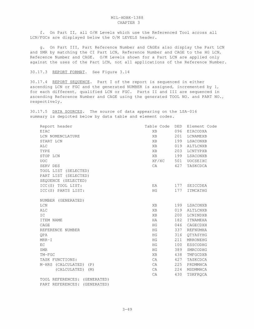
CHAPTER 3MIL-HDBK-1388
3-49
f. On Part II, all O/M Levels which use the Referenced Tool across allLCN/FGCs are displayed below the O/M LEVELS header.
g. On Part III, Part Reference Number and CAGEs also display the Part LCNand SMR by matching the CI Part LCN, Reference Number and CAGE to the HG LCN,Reference Number and CAGE. O/M Levels shown for a Part LCN are applied onlyagainst the uses of the Part LCN, not all applications of the Reference Number.
30.17.3 REPORT FORMAT. See Figure 3.14
30.17.4 REPORT SEQUENCE. Part I of the report is sequenced in eitherascending LCN or FGC and the generated NUMBER is assigned, incremented by 1,for each different, qualified LCN or FGC. Parts II and III are sequenced inascending Reference Number and CAGE using the generated TOOL NO. and PART NO.,respectively.
30.17.5 DATA SOURCES. The source of data appearing on the LSA-016summary is depicted below by data table and element codes.
Report header Table Code DED Element Code EIAC XB 096 EIACODXA LCN NOMENCLATURE XB 201 LCNAMEXB START LCN XB 199 LSACONXB ALC XB 019 ALTLCNXB TYPE XB 203 LCNTYPXB STOP LCN XB 199 LSACONXB UOC XF/XC 501 UOCSEIXC SERV DES CA 427 TASKCDCA TOOL LIST (SELECTED) PART LIST (SELECTED) SEQUENCE (SELECTED) ICC(S) TOOL LIST: EA 177 SEICCDEA ICC(S) PARTS LIST: HG 177 ITMCATHG
NUMBER (GENERATED) LCN XB 199 LSACONXB ALC XB 019 ALTLCNXB IC XB 200 LCNINDXB ITEM NAME HA 182 ITNAMEHA CAGE HG 046 CAGECDXH REFERENCE NUMBER HG 337 REFNUMHA QPA HG 316 QTYASYHG MRR-I HG 211 MRRONEHG EC HG 100 ESSCODHG SMR HG 389 SMRCODHG TM-FGC XB 438 TMFGCDXB TASK FUNCTIONS: CA 427 TASKCDCA M-HRS (CALCULATED) (P) CA 225 PRDMMHCA (CALCULATED) (M) CA 224 MSDMMHCA CA 430 TSKFRQCA TOOL REFERENCES: (GENERATED) PART REFERENCES: (GENERATED)

CHAPTER 3MIL-HDBK-1388
3-50
TOOL NO. (GENERATED) CAGE CG 046 TSCAGECG REFERENCE NUMBER CG 337 TSREFNCG ITEM NAME HA 182 ITNAMEHA O/M LEVELS CG 427 TASKCDCA PART NO. (GENERATED) CAGE CI 046 PROCAGCI REFERENCE NUMBER CI 337 PROREFCI ITEM NAME HA 182 ITNAMEHA LCN CI 199 PROLCNCI ALC CI 019 PROALCCI O/M LEVELS CI 427 TSKTCDCI SMR HG 389 SMRCODHG

CHAPTER 3MIL-HDBK-1388
3-51
lsa-016

CHAPTER 3MIL-HDBK-1388
3-52

CHAPTER 3MIL-HDBK-1388
3-53
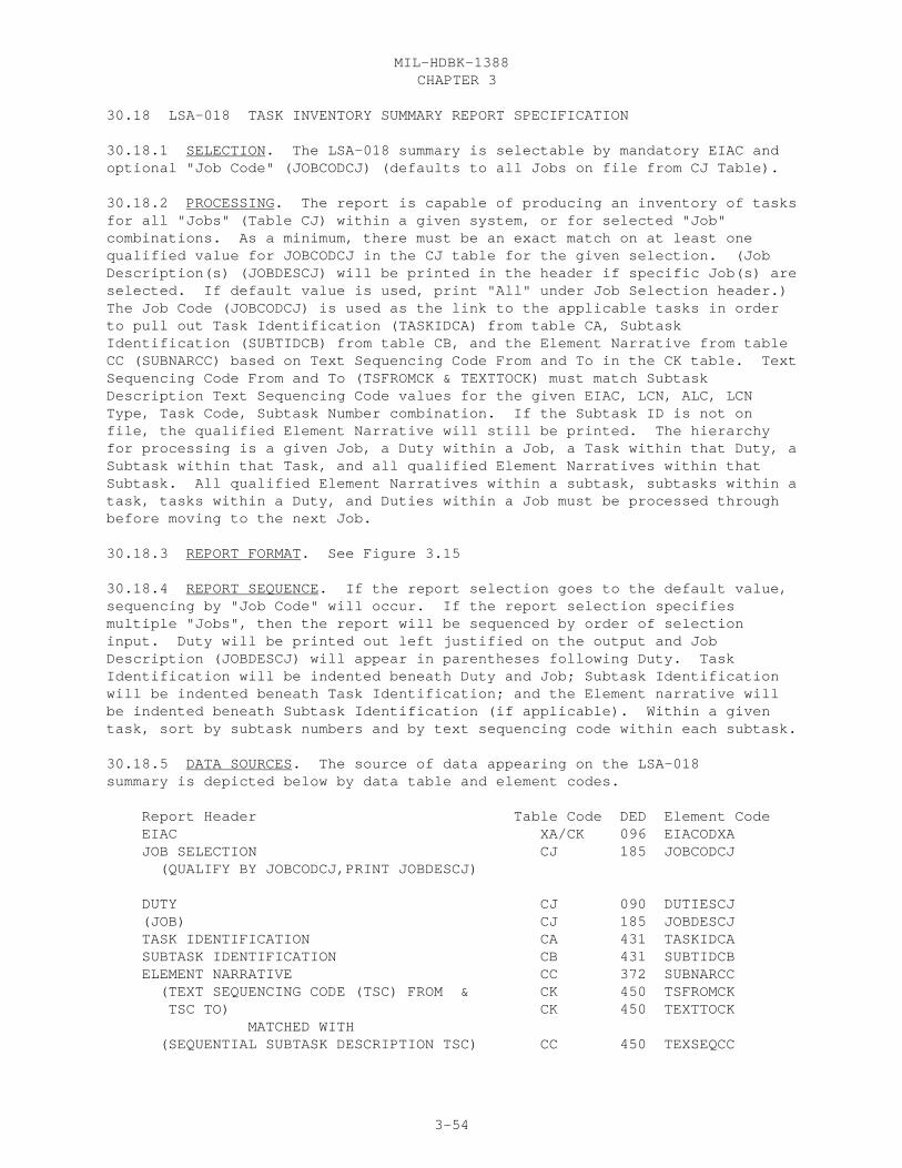
CHAPTER 3MIL-HDBK-1388
3-54
30.18 LSA-018 TASK INVENTORY SUMMARY REPORT SPECIFICATION
30.18.1 SELECTION. The LSA-018 summary is selectable by mandatory EIAC andoptional "Job Code" (JOBCODCJ) (defaults to all Jobs on file from CJ Table).
30.18.2 PROCESSING. The report is capable of producing an inventory of tasksfor all "Jobs" (Table CJ) within a given system, or for selected "Job"combinations. As a minimum, there must be an exact match on at least onequalified value for JOBCODCJ in the CJ table for the given selection. (JobDescription(s) (JOBDESCJ) will be printed in the header if specific Job(s) areselected. If default value is used, print "All" under Job Selection header.)The Job Code (JOBCODCJ) is used as the link to the applicable tasks in orderto pull out Task Identification (TASKIDCA) from table CA, SubtaskIdentification (SUBTIDCB) from table CB, and the Element Narrative from tableCC (SUBNARCC) based on Text Sequencing Code From and To in the CK table. TextSequencing Code From and To (TSFROMCK & TEXTTOCK) must match SubtaskDescription Text Sequencing Code values for the given EIAC, LCN, ALC, LCNType, Task Code, Subtask Number combination. If the Subtask ID is not onfile, the qualified Element Narrative will still be printed. The hierarchyfor processing is a given Job, a Duty within a Job, a Task within that Duty, aSubtask within that Task, and all qualified Element Narratives within thatSubtask. All qualified Element Narratives within a subtask, subtasks within atask, tasks within a Duty, and Duties within a Job must be processed throughbefore moving to the next Job.
30.18.3 REPORT FORMAT. See Figure 3.15
30.18.4 REPORT SEQUENCE. If the report selection goes to the default value,sequencing by "Job Code" will occur. If the report selection specifiesmultiple "Jobs", then the report will be sequenced by order of selectioninput. Duty will be printed out left justified on the output and JobDescription (JOBDESCJ) will appear in parentheses following Duty. TaskIdentification will be indented beneath Duty and Job; Subtask Identificationwill be indented beneath Task Identification; and the Element narrative willbe indented beneath Subtask Identification (if applicable). Within a giventask, sort by subtask numbers and by text sequencing code within each subtask.
30.18.5 DATA SOURCES. The source of data appearing on the LSA-018summary is depicted below by data table and element codes.
Report Header Table Code DED Element Code EIAC XA/CK 096 EIACODXA JOB SELECTION CJ 185 JOBCODCJ (QUALIFY BY JOBCODCJ,PRINT JOBDESCJ)
DUTY CJ 090 DUTIESCJ (JOB) CJ 185 JOBDESCJ TASK IDENTIFICATION CA 431 TASKIDCA SUBTASK IDENTIFICATION CB 431 SUBTIDCB ELEMENT NARRATIVE CC 372 SUBNARCC (TEXT SEQUENCING CODE (TSC) FROM & CK 450 TSFROMCK TSC TO) CK 450 TEXTTOCK MATCHED WITH (SEQUENTIAL SUBTASK DESCRIPTION TSC) CC 450 TEXSEQCC

CHAPTER 3MIL-HDBK-1388
3-55
LSA-018

CHAPTER 3MIL-HDBK-1388
3-56
30.19 LSA-019 TASK ANALYSIS SUMMARY REPORT SPECIFICATION
30.19.1. SELECTION. The LSA-019 summary is selectable by mandatory EIAC,Start LCN, Type, UOC. Optional selections include SERV DES, ALC, Stop LCN,Maintenance Level (M/L), Item Category Codes (ICCs), Display Option (LCN or TMFGC), Task Narrative option, task interval option, task function option andHardness Critical Procedures (HCP).
30.19.2 PROCESSING. LCNs are qualified within the selected LCN range with avalid Task Code that qualifies against selected SERV DES (4th position of TaskCode), selected M/L (3rd position Task Code), selected Task Interval (2ndposition Task Code), and selected Task Function (1st position Task Code) .
a. If the Task Narrative option is selected, then the Subtask Number,Sequential Subtask Narrative and associated Text Sequencing Code, Work AreaCode, Person ID, Mean Man Minutes, and Mean Minute Elapse Time are output forthe qualified tasks. All qualified tasks within the selection range will beoutput regardless if they have an entry in Table CC, or not. Referenced tasksand subtasks will be incorporated into referencing tasks where required. Adeveloper option may be to allow users to select whether referenced tasksshould be incorporated.
b. If the HCP option is selected, then only tasks with an associated HCPCode (element HRDCPCCA of table CA) of "Y" or "S" will qualify and be output(including narrative).
c. Either predicted or measured LSAR Elapsed Times and LSAR Man-Hours canbe output (measured takes first precedence).
d. The support items identified to perform the subject task arecategorized according to their respective ICC:
1. Items qualifying as "Support/Test Equipment and Tools" must havean ICC of D, G, H, M, N, P, R, 1-8, or AC.
2. Items qualifying as "Spare and Repair Parts" must have an ICC ofX, Y, Z, 9, AA, AB, or AE.
3. Items qualifying as "Other" must have an ICC of E, F, J, Q, S, T,W, AD, or AF.
e. There are spaces provided for manual entries onto this report forManually Measured Elapsed Time, Manually Measured Man-Hours, Actual QuantityUsed, Manual Evaluation, Reviewer’s Name, and Support Items Not Identified inthe LSAR.
30.19.3 REPORT FORMAT. See Figure 3.16
30.19.4 REPORT SEQUENCE. This report is sequenced by ascending LCN or TM FGC(depending on the Display Option chosen), then by ascending Task Code. Thesupport items portion is sequenced by support item type with Support/TestEquipment and Tools being first, then Spare and Repair Parts, then Other, thenspace is provided for Support Items Not Identified In LSAR. Within each ofthe first three categories of support items, sequencing is done by ascending

CHAPTER 3MIL-HDBK-1388
3-57
ICC, then ascending Reference Numbers.
30.19.5 DATA SOURCES. The source of data appearing on the LSA-019summary is depicted below by data table and element codes.
Report Header Table Code DED Element Code
EIAC XB 096 EIACODXA LCN NOMENCLATURE XB 201 LCNAMEXB START LCN XB 199 LSACONXB TYPE XB 209 LCNTYPXB ALC XB 019 ALTLCNXB STOP LCN XB 199 LSACONXB UOC XF 501 UOCSEIXC SERV DES CA 427 TASKCDCA M/L SELECT (SELECTED) CA 427 TASKCDCA ICC SELECTION (SELECTED) DISP OPT (SELECTED) TASK NARRATIVE SELECTION (SELECTED) CA 427 TASKCDCA HARDNESS CRITICAL PROCEDURES SELECTION CA 152 HRDCPCCA TASK INTERVAL CA 427 TASKCDCA TASK FUNCTION CA 427 TASKCDCA
LCN CA 199 LSACONXB ALC CA 019 ALTLCNXB REFERENCE NUMBER HG 337 REFNUMHA CAGE HG 046 CAGECDXH ITEM NAME HA 182 ITNAMEHA TM FUNCT GROUP CODE XB 438 TMFGCDXB TASK CD CA 427 TASKCDCA TASK IDENTIFICATION CA 431 TASKIDCA HCP CA 152 HRDCPCCA HMPC CA 155 HAZMPCCA TSK FREQ CA 430 TSKFRQCA MB CA 238 AORMSBCA LSAR ELAP TIME (MEASURED) CA 224 MSDMETCA LSAR ELAP TIME (PREDICTED) CA 224 PRDMETCA MANUALLY MEASURED ELAPSED TIME (ENTERED) SUBTASK NUMBER CC 407 SUBNUMCB TEXT SEQUENCE CODE CC 450 TEXSEQCC SEQUENTIAL TASK NARRATIVE CC 372 SUBNARCC WORK AREA CB 514 SUBWACCB PERS ID CD 288 SUBPIDCD MEAN MAN MINUTE CD 226 SUBMMMCD MEAN MINUTE ELAP TIME CB 227 SBMMETCB SSC CD 387 SKSPCDGA SS EVAL CD 388 SSECDECD LSAR MAN-HOURS (SUMMED PER SSC & PERS ID) CD 226 SUBMMMCD MANUALLY MEASURED MAN-HOURS (ENTERED) SUPPORT/TEST EQUIPMENT AND TOOLS (HEADER) ICC EA 177 SEICCDEA ITEM NAME HA 182 ITNAMEHA REFERENCE NUMBER CG 337 TSREFNCG CAGE CG 046 TSCAGECG
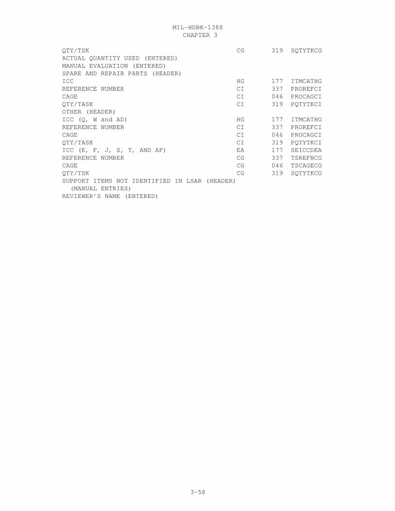
CHAPTER 3MIL-HDBK-1388
3-58
QTY/TSK CG 319 SQTYTKCG ACTUAL QUANTITY USED (ENTERED) MANUAL EVALUATION (ENTERED) SPARE AND REPAIR PARTS (HEADER) ICC HG 177 ITMCATHG REFERENCE NUMBER CI 337 PROREFCI CAGE CI 046 PROCAGCI QTY/TASK CI 319 PQTYTKCI OTHER (HEADER) ICC (Q, W and AD) HG 177 ITMCATHG REFERENCE NUMBER CI 337 PROREFCI CAGE CI 046 PROCAGCI QTY/TASK CI 319 PQTYTKCI ICC (E, F, J, S, T, AND AF) EA 177 SEICCDEA REFERENCE NUMBER CG 337 TSREFNCG CAGE CG 046 TSCAGECG QTY/TSK CG 319 SQTYTKCG SUPPORT ITEMS NOT IDENTIFIED IN LSAR (HEADER) (MANUAL ENTRIES) REVIEWER’S NAME (ENTERED)

CHAPTER 3MIL-HDBK-1388
3-59
LSA-019

CHAPTER 3MIL-HDBK-1388
3-60
30.20 LSA-023 MAINTENANCE PLAN, SUMMARY REPORT SPECIFICATION
30.20.1 SELECTION. The LSA-023 summary is selectable by mandatory EIAC, StartLCN, LCN TYPE, UOC, SERV DES and Report Part (1-4); and optional ALC (defaultis all ALC’s), Stop LCN (default is all LCN’s subordinate to, and including,the start LCN), ICC’s for part IV (default is all applicable ICC’s), DisplayOption (default is LCN), and Wartime/Peacetime (default is peacetime).
The report selections consist of: a. RPT PT: 1. Part 1, enter a (y) if part 1 of the 023 report is required, otherwise, leave blank. 2. Part 2, enter a (y) if part 2 of the 023 report is required, otherwise, leave blank. 3. Part 3, enter a (y) if part 3 of the 023 report is required, this includes both preventive and corrective maintenance. If only preventive maintenance is required enter a (P). If only corrective maintenance is required enter a (C). If part 3 is not required leave blank. 4. Part 4, enter a (y) if part 4 of the 023 report is required, otherwise, leave blank. If blank, no entry should be made in the ICC select.
b. If a (y) was entered in part 4 of RPT PT selection, then enter the ICC’s for which part 4 is required. See appendix E of MIL-STD-1388-2B for a listing and definitions of the various ICCs. If an (A) is entered in the ICC field, the output report will include the ICCS 8, M, D, 1, and 7; an entry of (B) will results in ICCs 2, 4, 5, 6, and H being included; an entry of (C) will result in ICCs of G, N, P, R, and 3 being included; and an entry of (V) will result in the ICC of V being included. These groupings will only have validity when definitions of the ICCs specified in appendix E of MIL-STD-1388-2B have been adhered to.
c. DISP OPT, enter an (X) if the report is to be sequenced by TM FGC in lieu of LCN; otherwise leave blank.
30.20.2 PROCESSING. The same qualifying criteria is used for all parts.
a. Part 1 of the report provides the technical and operational parameters for the items which are from the operations and maintenance requirements area, and several specific maintenance considerations, such as, whether the item is hardness critical, what type of support is being considered, the maintenance concept and the maintenance plan rationale. Part 1 should be pulled from the tables when the selection criteria has been met. To produce the report at least one AA and AG table should exist on file. Reference Number, CAGE and Item Designator Code may not appear if TYPE is Functional (F). The Reference Number is wrapped at the 16th position.
b. Part 2 of the report depicts reliability and maintainability parameters for the selected items in the order of comparative analyzed, allocated, predicted, and measured. Part 2 should be pulled from the
CHAPTER 3MIL-HDBK-1388
3-61
tables when the selection criteria has been met. To produce the report at least one BA and BD table should exist on file. NSN AND RELATED DATA, REFERENCE NUMBER, CAGE, MAOT, MAC. SMR, UI, and UNIT OF ISSUE PRICE may not appear if TYPE is Functional (F).
c. Part 3 of the report is divided into analyses of preventive and corrective maintenance tasks by maintenance level and hardware LCN designation. The preventive maintenance task area identified by the 2nd position of the task code (Q, C, P, M, N, L, and B). The corrective maintenance tasks are identified by the second position of the task code (all that are not preventive). This part identifies personnel and training requirement considerations. To produce the report the CA and its corresponding CD table should exist on file. The NO SSC can be calculated by summing up the number of Subtask Person Identifiers table CD for a given Skill Specialty Code and Task Code. The (P) or (M) preceding the and ELAP TIME values on the output represent predicted and measured, respectively. Where a measured value has not been input to the LSAR, the report will default to the predicted value.
d. Part 4 of this report provides a listing of all support items required to perform each task meeting the report selection criteria by ICC. To produce the report at least one CA, CG, EA, and HA table should exist on file.
e. In order to exercise the display option the TM FGC must be entered in the XB table.
f. Each part of this report should start at the top of a new page.
30.20.3 REPORT FORMAT. See Figure 3.17
30.20.4 REPORT SEQUENCING. a. Depending upon the display option: 1. If the display option of TM FGC is selected then within all report parts the output is sorted in ascending TM FGC then LCN sequence. 2. If the display option of TM FGC is not selected then within all report parts the output is sorted in ascending LCN then TM FGC sequence.
b. For Parts 1 and 2, 4.a.1 and 4.a.2 is the sequencing used.
c. Part III A and B should be sorted by Maintenance Level, the first being crew the last being depot for that service designator sub-table. Within this sequence, Tasks are sorted in ascending LCN, then ascending Task Code (starting with the first position).
d. Numbers 4a.1 and .2 hold true for Part 4 of the output report.
30.20.5 DATA SOURCES. The source of the data appearing on the LSA-023summary is depicted below by data table and element codes.
PART I
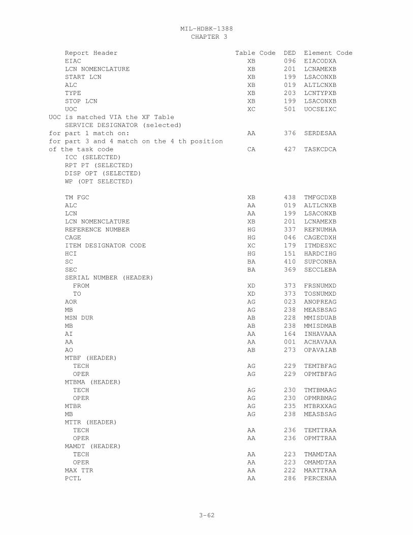
CHAPTER 3MIL-HDBK-1388
3-62
Report Header Table Code DED Element Code EIAC XB 096 EIACODXA LCN NOMENCLATURE XB 201 LCNAMEXB START LCN XB 199 LSACONXB ALC XB 019 ALTLCNXB TYPE XB 203 LCNTYPXB STOP LCN XB 199 LSACONXB UOC XC 501 UOCSEIXCUOC is matched VIA the XF Table SERVICE DESIGNATOR (selected)for part 1 match on: AA 376 SERDESAAfor part 3 and 4 match on the 4 th position of the task code CA 427 TASKCDCA ICC (SELECTED) RPT PT (SELECTED) DISP OPT (SELECTED) WP (OPT SELECTED)
TM FGC XB 438 TMFGCDXB ALC AA 019 ALTLCNXB LCN AA 199 LSACONXB LCN NOMENCLATURE XB 201 LCNAMEXB REFERENCE NUMBER HG 337 REFNUMHA CAGE HG 046 CAGECDXH ITEM DESIGNATOR CODE XC 179 ITMDESXC HCI HG 151 HARDCIHG SC BA 410 SUPCONBA SEC BA 369 SECCLEBA SERIAL NUMBER (HEADER) FROM XD 373 FRSNUMXD TO XD 373 TOSNUMXD AOR AG 023 ANOPREAG MB AG 238 MEASBSAG MSN DUR AB 228 MMISDUAB MB AB 238 MMISDMAB AI AA 164 INHAVAAA AA AA 001 ACHAVAAA AO AB 273 OPAVAIAB MTBF (HEADER) TECH AG 229 TEMTBFAG OPER AG 229 OPMTBFAG MTBMA (HEADER) TECH AG 230 TMTBMAAG OPER AG 230 OPMRBMAG MTBR AG 235 MTBRXXAG MB AG 238 MEASBSAG MTTR (HEADER) TECH AA 236 TEMTTRAA OPER AA 236 OPMTTRAA MAMDT (HEADER) TECH AA 223 TMAMDTAA OPER AA 223 OMAMDTAA MAX TTR AA 222 MAXTTRAA PCTL AA 286 PERCENAA
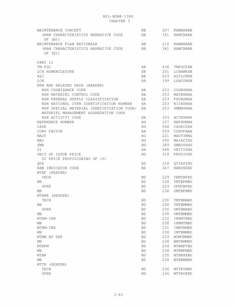
CHAPTER 3MIL-HDBK-1388
3-63
MAINTENANCE CONCEPT BB 207 RAMNARBB (RAM CHARACTERISTICS NARRATIVE CODE BB 341 RAMCNABB OF (B)) MAINTENANCE PLAN RATIONALE BB 210 RAMNARBB (RAM CHARACTERISTICS NARRATIVE CODE BB 341 RAMCNABB OF (E))
PART II TM FGC XB 438 TMFGCDXB LCN NOMENCLATURE XB 201 LCNAMEXB ALC BA 019 ALTLCNXB LCN BA 199 LSACONXB NSN AND RELATED DATA (HEADER) NSN COGNIZANCE CODE HA 253 COGNSNHA NSN MATERIEL CONTROL CODE HA 253 MATNSNHA NSN FEDERAL SUPPLY CLASSIFICATION HA 253 FSCNSNHA NSN NATIONAL ITEM IDENTIFICATION NUMBER HA 253 NIINSNHA NSN SPECIAL MATERIAL IDENTIFICATION CODE/ HA 253 SMMNSNHA MATERIEL MANAGEMENT AGGREGATION CODE NSN ACTIVITY CODE HA 253 ACTNSNHA REFERENCE NUMBER HG 337 REFNUMHA CAGE HG 046 CAGECDXH CONV FACTOR BA 059 CONVFABA MAOT HG 221 MAOTIMHG MAC HG 206 MAIACTHG SMR HG 389 SMRCODHG UI HA 488 UNITISHA UNIT OF ISSUE PRICE HD 314 PROUIPHD UI PRICE PROVISIONING OF (Y) QPA HG 316 QTYASYHG RAM INDICATOR CODE BD 347 RAMINDBD MTBF (HEADER) TECH BD 229 TEMTBFBD MB BD 238 TMTBFMBD OPER BD 229 OPMTBFBD MB BD 238 OMTBFMBD MTBMA (HEADER) TECH BD 230 TMTBMABD MB BD 238 TMTBMMBD OPER BD 230 OMTBMABD MB BD 238 OMTBMMBD MTBM-INH BD 232 INHMTBBD MB BD 238 INHMTMBD MTBM-IND BD 231 INMTBMBD MB BD 238 IMTBMMBD MTBM NO DEF BD 233 NOMTBMBD MB BD 238 NMTBMMBD MTBPM BD 234 MTBMPVBD MB BD 238 MTBMPMBD MTBR BD 235 MTBRXXBD MB BD 238 MTBRMBBD MTTR (HEADER) TECH BD 236 MTTRTHBD OPER BD 236 MTTROPBD
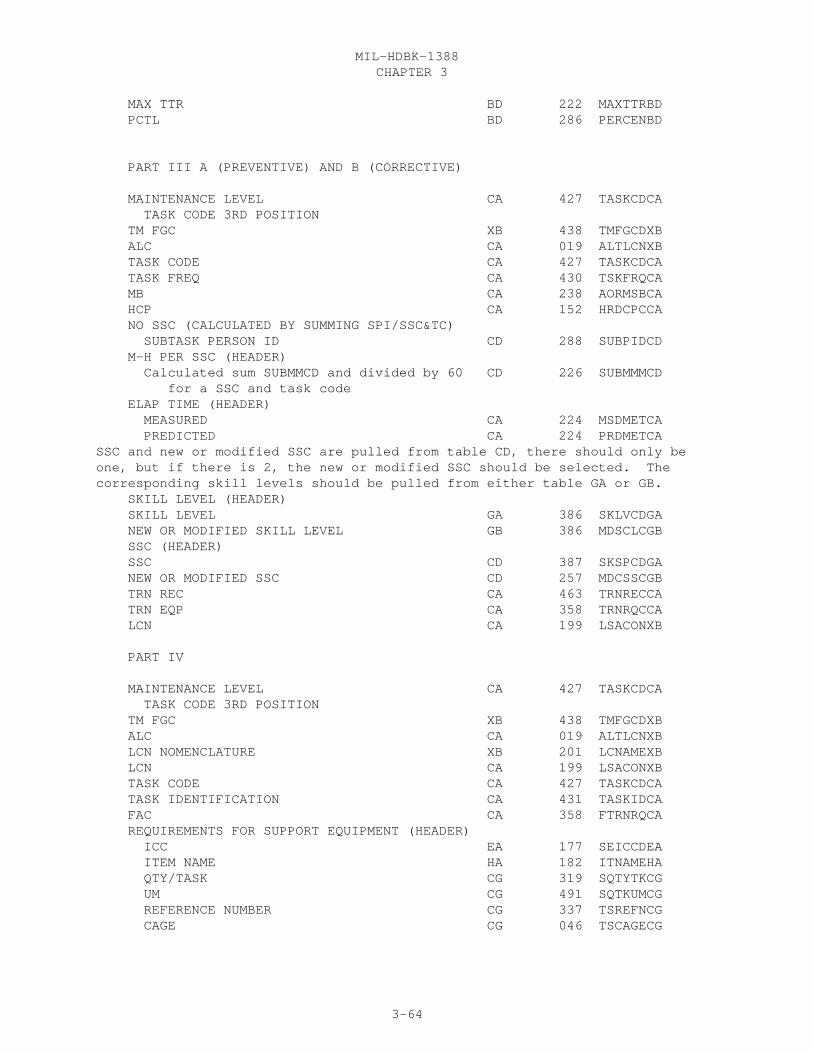
CHAPTER 3MIL-HDBK-1388
3-64
MAX TTR BD 222 MAXTTRBD PCTL BD 286 PERCENBD
PART III A (PREVENTIVE) AND B (CORRECTIVE)
MAINTENANCE LEVEL CA 427 TASKCDCA TASK CODE 3RD POSITION TM FGC XB 438 TMFGCDXB ALC CA 019 ALTLCNXB TASK CODE CA 427 TASKCDCA TASK FREQ CA 430 TSKFRQCA MB CA 238 AORMSBCA HCP CA 152 HRDCPCCA NO SSC (CALCULATED BY SUMMING SPI/SSC&TC) SUBTASK PERSON ID CD 288 SUBPIDCD M-H PER SSC (HEADER) Calculated sum SUBMMCD and divided by 60 CD 226 SUBMMMCD for a SSC and task code ELAP TIME (HEADER) MEASURED CA 224 MSDMETCA PREDICTED CA 224 PRDMETCASSC and new or modified SSC are pulled from table CD, there should only beone, but if there is 2, the new or modified SSC should be selected. Thecorresponding skill levels should be pulled from either table GA or GB. SKILL LEVEL (HEADER) SKILL LEVEL GA 386 SKLVCDGA NEW OR MODIFIED SKILL LEVEL GB 386 MDSCLCGB SSC (HEADER) SSC CD 387 SKSPCDGA NEW OR MODIFIED SSC CD 257 MDCSSCGB TRN REC CA 463 TRNRECCA TRN EQP CA 358 TRNRQCCA LCN CA 199 LSACONXB
PART IV
MAINTENANCE LEVEL CA 427 TASKCDCA TASK CODE 3RD POSITION TM FGC XB 438 TMFGCDXB ALC CA 019 ALTLCNXB LCN NOMENCLATURE XB 201 LCNAMEXB LCN CA 199 LSACONXB TASK CODE CA 427 TASKCDCA TASK IDENTIFICATION CA 431 TASKIDCA FAC CA 358 FTRNRQCA REQUIREMENTS FOR SUPPORT EQUIPMENT (HEADER) ICC EA 177 SEICCDEA ITEM NAME HA 182 ITNAMEHA QTY/TASK CG 319 SQTYTKCG UM CG 491 SQTKUMCG REFERENCE NUMBER CG 337 TSREFNCG CAGE CG 046 TSCAGECG

CHAPTER 3MIL-HDBK-1388
3-65
LSA-023

CHAPTER 3MIL-HDBK-1388
3-66

CHAPTER 3MIL-HDBK-1388
3-67

CHAPTER 3MIL-HDBK-1388
3-68

CHAPTER 3MIL-HDBK-1388
3-69
30.21 LSA-024 MAINTENANCE PLAN REPORT SPECIFICATION
30.21.1 SELECTION. The LSA-024 summary is selectable by mandatory EIAC, StartLCN, UOC, and SERV DES; and optional ALC, Stop LCN, and LCN Type.
The report selections consist of the following: a. Report Parts Selected: 1. Enter the number of the summary parts desired; "1" for Part I; "2"for Parts I and II; and "3" for Parts I, II and III. If left blank, all threeparts will be produced. 2. If Part I only is selected and no header information is desired,the remainder of this selection criteria may be left blank.
b. Equipment Type Code - If an "S" (Support Equipment) is entered,interval and maintenance cycle will be displayed. If the code is "A" (Air),"M" (Missile) or blank, interval and maintenance cycle will not be displayed.
c. Item Category Code - Enter the ICCs for the types of support items tobe displayed in Parts II and III, respectively. For ease of selection, ifICCs 8, M, D, 1, and 7 are all desired, enter an "A". If ICCs 2, 4, 5, 6, andH are all desired, enter a "B". If ICCs N, P, R, G, and 3 are all desired,enter a "C".
d. Display Option - The report may be sequenced by TM FGC in lieu of LCNif so desired.
e. Maintenance Level - If Parts II and III of the report are to displayonly a specific maintenance level(s), enter the appropriate code(s). If thisfield is left blank, all maintenance levels will be selected.
f. Technical Factor Basis is always 100 Flight Hours (was an option underMIL-STD-1388-2A).
30.21.2 PROCESSING. The same qualifying criteria is used for all three partsof this report. Task Codes must first qualify by matching on selected SERVDES, then maintenance levels selected. As a minimum, there must be one LCNwithin the selected range with a valid entry in table BB for either ItemFunction (element RAMNARBB with a narrative code of "A") or Maintenance Concept(element RAMNARBB with a narrative code of "B"). For Part II Reference Numberand CAGE to be produced, there must be a match between the LCN from table CAand the LCN from table HG (for the corresponding Reference Number and CAGE) ifthe LCN selection is physical (LCN Type of "P"). If the LCN selection isfunctional (LCN Type of "F"), then a matching physical LCN must be found intable XG before being matched against table HG LCNs.
a. The following definitions are for the header information of theLSA-024 summary which are not contained in the LSAR. 1. Date of Initial Submission/Revision/Date of Revision - A nineteenposition field containing the date of the initial submission of themaintenance plan, the alphabetic revision indicator, and the date of thecurrent revision. The dates and revision should be entered in the followingformat including slashes and dashes: MM-DD-YY/A/MM-DD-YY. 2. Preparing Activity - A fifteen position field containing the nameof the performing activity having responsibility for the data.

CHAPTER 3MIL-HDBK-1388
3-70
3. Prepared By - A fifteen position field containing the name of theindividual having responsibility for accuracy of the data. 4. DLSC Screen Date - An eight position field containing the dateindicating when screening results were accepted by the government on allrepairables items. The date should be entered in the following format,including dashes: MM-DD-YY. 5. Navy Ammunition Logistic Code (NALC) - A four positionalphanumeric code identifying the generic description within the FederalSupply Class. The NALC is assigned by Ships Parts Control Center (SPCC). TheNALC is used for fleet reporting/requisitioning of ammunition and to indicatefunctional interchangeability of items. 6. Maintenance Plan Number - A number identifying each maintenanceplan. The Maintenance Plan Number is assigned by the requiring authority (DED180).
b. The following definitions and calculations are for technical factors: 1. Interval - The recommended operating hours or usage rate precededby an alpha character indicating the type of maintenance requirements for anitem. The calculation and codes are as follows:
Annual Operating Requirement (AOR) (Conversion Factor) Interval = ------------------------------------------------------ n � Task Frequency i=1 P - Preventive (1st position Task Code of A or Z) C - Corrective (1st position Task Code of B, G, R, J, H, L, K, N, S, O or W) T - Servicing (1st position Task Code of P, M, or C) U - Calibration (1st position Task Code of D, E, or F)
AOR - Pulled from table AG (element ANOPREAG) based on the values entered for AORLCNCA, AORALCCA, AORTYPCA, and AORMSBCA in table CA for the given item.
Conversion Factor - Pulled from table BA (element CONVFABA).
Task Frequency - Pulled from table CA (element TSKFRQCA). Summation of Task Frequencies within given type of maintenancefor subject LCN.
2. Maintenance Cycle - This data is calculated as follows:
Maintenance Cycle = AOR x Conversion Factor
AOR - Pulled from table AG (element ANOPREAG) based on the values entered for AORLCNCA, AORALCCA, AORTYPCA, and AORMSBCA in table CA for the given item.
Conversion Factor - Pulled from table BA (element CONVFABA).
c. Other technical factors are computed as follows:
MRF (Repairables) = [MTD(D) + MTD(CAD)] X MRR
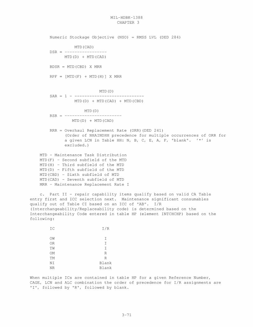
CHAPTER 3MIL-HDBK-1388
3-71
Numeric Stockage Objective (NSO) = RMSS LVL (DED 284)
MTD(CAD) DSR = ----------------- MTD(D) + MTD(CAD)
BDSR = MTD(CBD) X MRR
RPF = [MTD(F) + MTD(H)] X MRR
MTD(D) SAR = 1 - ---------------------------- MTD(D) + MTD(CAD) + MTD(CBD)
MTD(D) RSR = ----------------------- MTD(D) + MTD(CAD)
RRR = Overhaul Replacement Rate (ORR)(DED 241) (Order of NHAINDHH precedence for multiple occurrences of ORR for a given LCN in Table HH: N, B, C, E, A, F, "blank". ’*’ is excluded.)
MTD - Maintenance Task Distribution MTD(F) - Second subfield of the MTD MTD(H) - Third subfield of the MTD MTD(D) - Fifth subfield of the MTD MTD(CBD) - Sixth subfield of MTD MTD(CAD) - Seventh subfield of MTD MRR - Maintenance Replacement Rate I
c. Part II - repair capability items qualify based on valid CA Tableentry first and ICC selection next. Maintenance significant consumablesqualify out of Table CI based on an ICC of "AB". I/R(Interchangeability/Replaceability code) is determined based on theInterchangeability Code entered in table HP (element INTCHCHP) based on thefollowing:
IC I/R
OW I OR I TW I OM R TM R NI Blank NR Blank
When multiple ICs are contained in table HP for a given Reference Number,CAGE, LCN and ALC combination the order of precedence for I/R assignments are"I", followed by "R", followed by blank.

CHAPTER 3MIL-HDBK-1388
3-72
d. Part III - REQ NO (Requirement Number) is a five position counter(first four positions numeric starting with 0001, and last position alphabeticP, C, T, or U) based on the type of task (Predictive (P), Corrective (C),Servicing (T), or Calibration (U). The counter begins at 0001 for each typeof task and resets to 0001 for a new LCN.
e. Page breaks are required between Part I and II and Part II and III.For Part II, Repairable Items, the report headers (i.e., LCN, ALC, ReferenceNumber, etc.) are repeated for each item to be output in this section.
30.21.3 REPORT FORMAT. See Figure 3.18
30.21.4 REPORT SEQUENCE. Part I is sequenced by ascending LCN (or TM FGC ifselected in the Display Option). Part II is sequenced by ascending LCN andascending Reference Number within each LCN. Part III is sequenced byascending LCN, then maintenance type with Predicted first, Corrective second,Service third, and Calibration fourth, then by maintenance level (Crew-Depot).
30.21.5 DATA SOURCES. The source of data appearing on the LSA-024summary is depicted below by data table and element codes.
Report Header Table Code DED Element Code
EIAC XB 096 EIACODXA LCN NOMENCLATURE XB 201 LCNAMEXB START LCN XB 199 LSACONXB TYPE XB 209 LCNTYPXB ALC XB 019 ALTLCNXB STOP LCN XB 199 LSACONXB UOC XF 501 UOCSEIXC SERV DES CA 427 TASKCDCA DISP OPT (SELECTED) MAINTENANCE LEVEL OPTION (SELECTED) CA 427 TASKCDCA PART 2 ITEM CATEGORY CODES (SELECTED) HG 181 ITMCATHG PART 3 ITEM CATEGORY CODES (SELECTED) EA/HG 181 SEICCDEA EQUIPMENT TYPE CODE (SELECTED) REPORT PARTS (SELECTED)
PART I - GENERAL CONSIDERATIONS (HEADER) REFERENCE NUMBER HG 337 REFNUMHA CAGE HG 046 CAGECDXH ITEM DESIGNATOR XC 179 ITMDESXC NSN & RELATED DATA HA 253 COGNSNHA SMMNSNHA MATNSNHA FSCNSNHA NIINSNHA ACTNSNHA MAINTENANCE PLAN NUMBER (SELECTED THROUGHPUT) SERD NUMBER (SELECTED THROUGHPUT) EF 416 SERDNOEF TM FGC XB 438 TMFGCDXB SMR CODE HG 389 SMRCODHG DLSC SCREEN (SELECTED THROUGHPUT) DATE OF SUB/REV/DATE OF REVISION (THROUGHPUT)
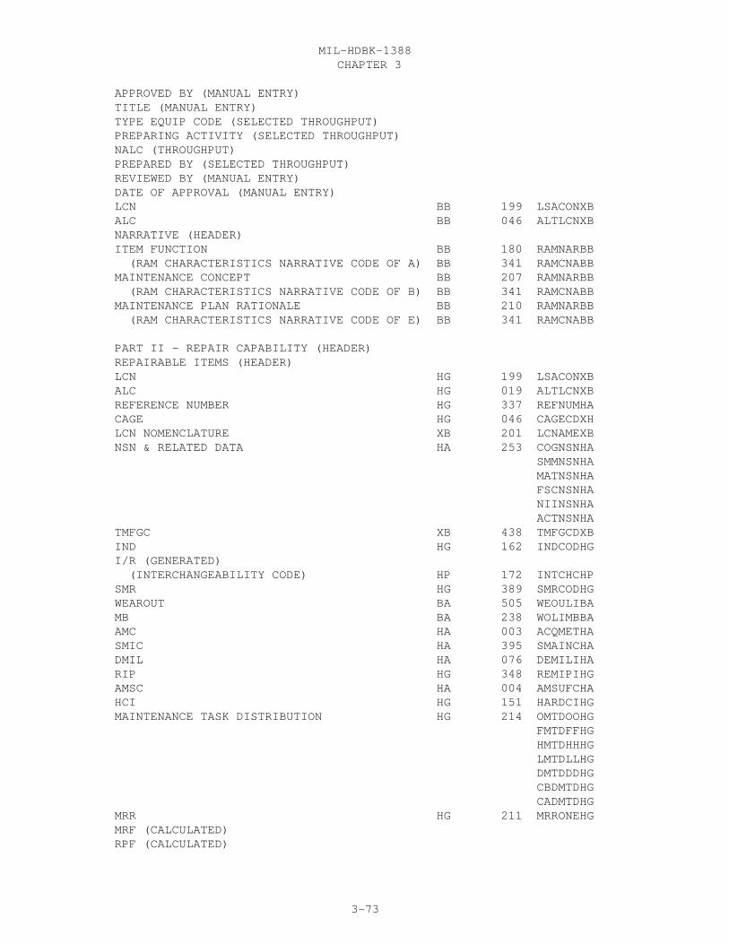
CHAPTER 3MIL-HDBK-1388
3-73
APPROVED BY (MANUAL ENTRY) TITLE (MANUAL ENTRY) TYPE EQUIP CODE (SELECTED THROUGHPUT) PREPARING ACTIVITY (SELECTED THROUGHPUT) NALC (THROUGHPUT) PREPARED BY (SELECTED THROUGHPUT) REVIEWED BY (MANUAL ENTRY) DATE OF APPROVAL (MANUAL ENTRY) LCN BB 199 LSACONXB ALC BB 046 ALTLCNXB NARRATIVE (HEADER) ITEM FUNCTION BB 180 RAMNARBB (RAM CHARACTERISTICS NARRATIVE CODE OF A) BB 341 RAMCNABB MAINTENANCE CONCEPT BB 207 RAMNARBB (RAM CHARACTERISTICS NARRATIVE CODE OF B) BB 341 RAMCNABB MAINTENANCE PLAN RATIONALE BB 210 RAMNARBB (RAM CHARACTERISTICS NARRATIVE CODE OF E) BB 341 RAMCNABB
PART II - REPAIR CAPABILITY (HEADER) REPAIRABLE ITEMS (HEADER) LCN HG 199 LSACONXB ALC HG 019 ALTLCNXB REFERENCE NUMBER HG 337 REFNUMHA CAGE HG 046 CAGECDXH LCN NOMENCLATURE XB 201 LCNAMEXB NSN & RELATED DATA HA 253 COGNSNHA SMMNSNHA MATNSNHA FSCNSNHA NIINSNHA ACTNSNHA TMFGC XB 438 TMFGCDXB IND HG 162 INDCODHG I/R (GENERATED) (INTERCHANGEABILITY CODE) HP 172 INTCHCHP SMR HG 389 SMRCODHG WEAROUT BA 505 WEOULIBA MB BA 238 WOLIMBBA AMC HA 003 ACQMETHA SMIC HA 395 SMAINCHA DMIL HA 076 DEMILIHA RIP HG 348 REMIPIHG AMSC HA 004 AMSUFCHA HCI HG 151 HARDCIHG MAINTENANCE TASK DISTRIBUTION HG 214 OMTDOOHG FMTDFFHG HMTDHHHG LMTDLLHG DMTDDDHG CBDMTDHG CADMTDHG MRR HG 211 MRRONEHG MRF (CALCULATED) RPF (CALCULATED)

CHAPTER 3MIL-HDBK-1388
3-74
DSR (CALCULATED) BDSR (CALCULATED) NSO HG 329 RMSSLIHG SAR (CALCULATED) RSR (CALCULATED) RRR HH 281 OVHREPHH INTERVAL (CALCULATED) MAINT CYCLE (CALCULATED)
MAINTENANCE SIGNIFICANT CONSUMABLES (HEADER) LCN HG 199 LSACONXB ALC HG 019 ALTLCNXB REFERENCE NUMBER HG 337 REFNUMHA CAGE HG 046 CAGECDXH ITEM NAME HA 188 ITNAMEHA NSN & RELATED DATA HA 253 COGNSNHA SMMNSNHA MATNSNHA FSCNSNHA NIINSNHA ACTNSNHA IND HG 162 INDCODHG TM FGC HK 438 TMFGCDHK I/R (GENERATED) (INTERCHANGEABILITY CODE) HP 182 INTCHCHP
PART III - MAINTENANCE REQUIREMENTS (HEADER) LCN CA 199 LSACONXB ALC CA 019 ALTLCNXB REQ NO (GENERATED) TASK CD CA 427 TASKCDCA TASK IDENTIFICATION CA 431 TASKIDCA TSK FREQ CA 430 TSKFRQCA MB CA 238 AORMSBCA INTERVAL (CALCULATED) TM FGC XB 438 TMFGCDXB
SUPPORT ITEM REQUIREMENTS (HEADER) ICC (1-8, D, E, F, G, H, J, M, N, P, R, EA 177 SEICCDEA S, T, U, V, AC, AF) REFERENCE NUMBER CG 337 TSREFNCG CAGE CG 046 TSCAGECG ITEM NAME HA 182 ITNAMEHA or ICC (9, K, L, Q, W, X, Y, Z, AA, AB, AD, AE) HG 177 ITMCATHG REFERENCE NUMBER CI 337 PROREFCI CAGE CI 046 PROCAGCI ITEM NAME HA 182 ITNAMEHA

CHAPTER 3MIL-HDBK-1388
3-75
LSA-024

CHAPTER 3MIL-HDBK-1388
3-76

CHAPTER 3MIL-HDBK-1388
3-77

CHAPTER 3MIL-HDBK-1388
3-78

CHAPTER 3MIL-HDBK-1388
3-79
30.22 LSA-025 PACKAGING REQUIREMENTS DATA REPORT SPECIFICATION
30.22.1 SELECTION. The LSA-025 summary is selected by either a mandatorySTART LCN or REFERENCE NUMBER and CAGE. Optional Selections are ALC, STOP LCN,UOC, DEGREE OF PROT, and TAPE OPTION. LCN-TYPE (TYPE) must always be "P". IfReference Number/CAGE are selected, then all option features except DEGREE OFPROT are ignored.
30.22.2 PROCESSING. At least one Reference Number/CAGE combination within theLCN range must have an entry in table HF in order to produce an LSA-025summary. When more than one LCN for the same Reference Number/CAGE combinationis qualified, only one set of packaging requirements is output.
a. ALTHOUGH NOT DESCRIBED IN THE STANDARD, If the tape option isselected, then a five position sequence number is assigned to the RESERVEDpositions, immediately following the Card Type in card column one. Thesequence number of 0001 and are assigned in ascending ASCII numeric order.The fifth position of the sequence number is left blank.
b. Supplemental Card Indicator (SCI) generated based on the following:
If only an "A" card is used, the SCI is "1". If an "A" and "B" card are used, the SCI is "2". If an "A", "B", and "C" card are used, the SCI is "3". If an "A", "B", and "D" card are used, the SCI is "4".
30.22.3 REPORT FORMAT. See Figure 3.19
30.22.4 REPORT SEQUENCE. The report is sequenced in ascending ReferenceNumber and CAGE sequence. Within each Reference Number, Degree of Protection(DOP) (A, B, C) are output in ascending DOP sequence.
30.22.5 DATA SOURCE. The source of data appearing on the LSA-025 summary isdepicted below by data table and element codes.
Report header Table Code DED Element Code EIAC HG 096 EIACODXA ITEM NAME HA 182 ITNAMEHA START LCN HG 199 LSACONXB ALC HG 019 ALTLCNXB LCN TYPE HG 203 LCNTYPXB STOP LCN HG 199 LSACONXB UOC HO/XC 501 UOCSEIXC DEGREE OF PROT HF 074 DEGPROHF TAPE OPTION (SELECTED)
CAGE HF 046 CAGECDXH REFERENCE NUMBER HF 337 REFNUMHA ITEM NAME HA 182 ITNAMEHA CARD (GENERATED) SEQUENCE NUMBER (GENERATED FOR ONLY TAPE OPTION) NSN AND MTL-MGT-CD HA 253 FSCNSNHA HA 253 NIINSNHA
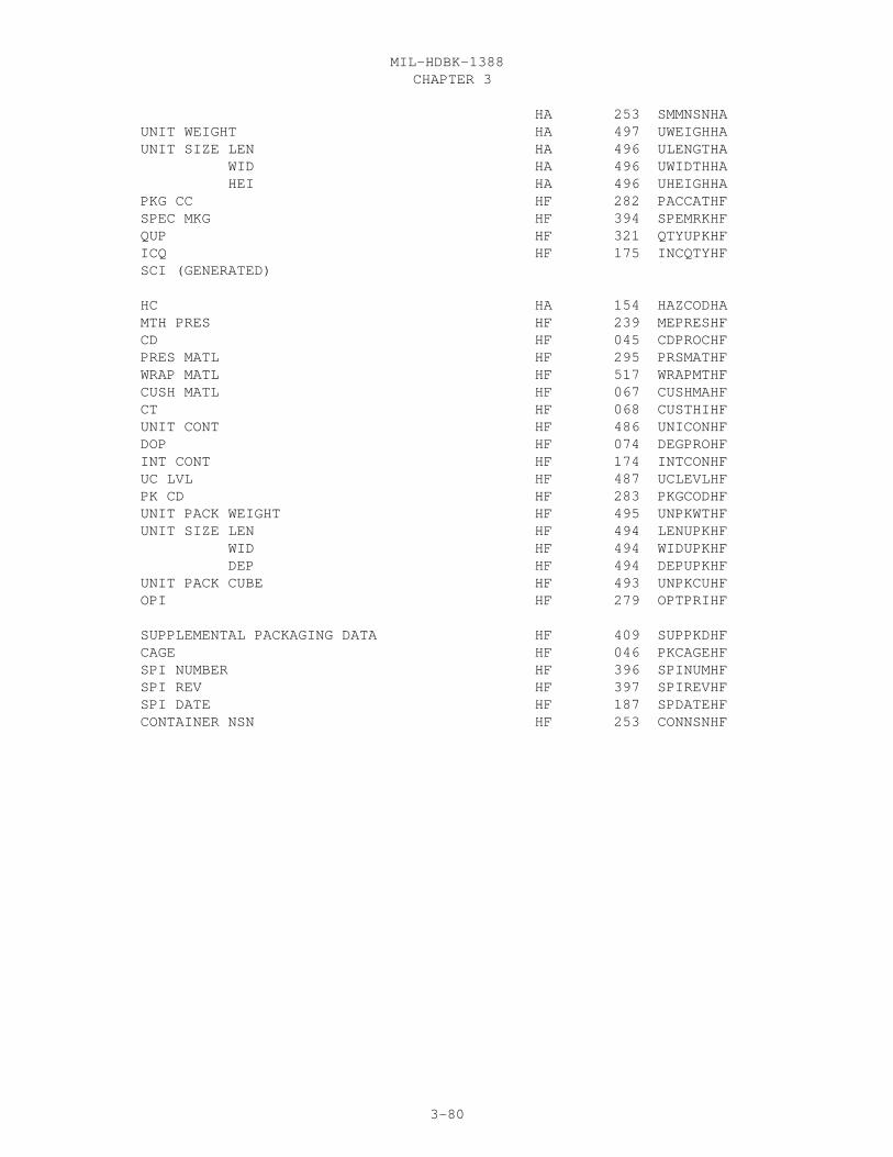
CHAPTER 3MIL-HDBK-1388
3-80
HA 253 SMMNSNHA UNIT WEIGHT HA 497 UWEIGHHA UNIT SIZE LEN HA 496 ULENGTHA WID HA 496 UWIDTHHA HEI HA 496 UHEIGHHA PKG CC HF 282 PACCATHF SPEC MKG HF 394 SPEMRKHF QUP HF 321 QTYUPKHF ICQ HF 175 INCQTYHF SCI (GENERATED)
HC HA 154 HAZCODHA MTH PRES HF 239 MEPRESHF CD HF 045 CDPROCHF PRES MATL HF 295 PRSMATHF WRAP MATL HF 517 WRAPMTHF CUSH MATL HF 067 CUSHMAHF CT HF 068 CUSTHIHF UNIT CONT HF 486 UNICONHF DOP HF 074 DEGPROHF INT CONT HF 174 INTCONHF UC LVL HF 487 UCLEVLHF PK CD HF 283 PKGCODHF UNIT PACK WEIGHT HF 495 UNPKWTHF UNIT SIZE LEN HF 494 LENUPKHF WID HF 494 WIDUPKHF DEP HF 494 DEPUPKHF UNIT PACK CUBE HF 493 UNPKCUHF OPI HF 279 OPTPRIHF
SUPPLEMENTAL PACKAGING DATA HF 409 SUPPKDHF CAGE HF 046 PKCAGEHF SPI NUMBER HF 396 SPINUMHF SPI REV HF 397 SPIREVHF SPI DATE HF 187 SPDATEHF CONTAINER NSN HF 253 CONNSNHF

CHAPTER 3MIL-HDBK-1388
3-81
LSA-025
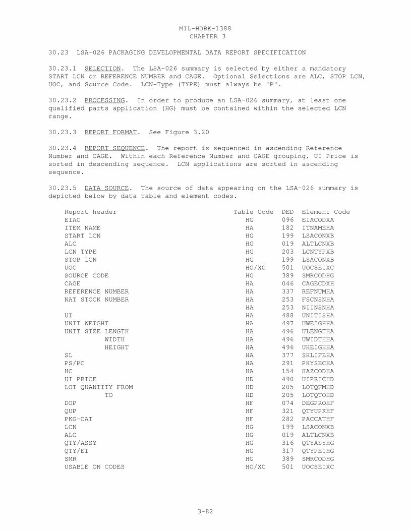
CHAPTER 3MIL-HDBK-1388
3-82
30.23 LSA-026 PACKAGING DEVELOPMENTAL DATA REPORT SPECIFICATION
30.23.1 SELECTION. The LSA-026 summary is selected by either a mandatorySTART LCN or REFERENCE NUMBER and CAGE. Optional Selections are ALC, STOP LCN,UOC, and Source Code. LCN-Type (TYPE) must always be "P".
30.23.2 PROCESSING. In order to produce an LSA-026 summary, at least onequalified parts application (HG) must be contained within the selected LCNrange.
30.23.3 REPORT FORMAT. See Figure 3.20
30.23.4 REPORT SEQUENCE. The report is sequenced in ascending ReferenceNumber and CAGE. Within each Reference Number and CAGE grouping, UI Price issorted in descending sequence. LCN applications are sorted in ascendingsequence.
30.23.5 DATA SOURCE. The source of data appearing on the LSA-026 summary isdepicted below by data table and element codes.
Report header Table Code DED Element Code EIAC HG 096 EIACODXA ITEM NAME HA 182 ITNAMEHA START LCN HG 199 LSACONXB ALC HG 019 ALTLCNXB LCN TYPE HG 203 LCNTYPXB STOP LCN HG 199 LSACONXB UOC HO/XC 501 UOCSEIXC SOURCE CODE HG 389 SMRCODHG CAGE HA 046 CAGECDXH REFERENCE NUMBER HA 337 REFNUMHA NAT STOCK NUMBER HA 253 FSCNSNHA HA 253 NIINSNHA UI HA 488 UNITISHA UNIT WEIGHT HA 497 UWEIGHHA UNIT SIZE LENGTH HA 496 ULENGTHA WIDTH HA 496 UWIDTHHA HEIGHT HA 496 UHEIGHHA SL HA 377 SHLIFEHA PS/PC HA 291 PHYSECHA HC HA 154 HAZCODHA UI PRICE HD 490 UIPRICHD LOT QUANTITY FROM HD 205 LOTQFMHD TO HD 205 LOTQTOHD DOP HF 074 DEGPROHF QUP HF 321 QTYUPKHF PKG-CAT HF 282 PACCATHF LCN HG 199 LSACONXB ALC HG 019 ALTLCNXB QTY/ASSY HG 316 QTYASYHG QTY/EI HG 317 QTYPEIHG SMR HG 389 SMRCODHG USABLE ON CODES HO/XC 501 UOCSEIXC

CHAPTER 3MIL-HDBK-1388
3-83
LSA-026
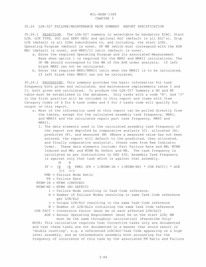
CHAPTER 3MIL-HDBK-1388
3-84
30.24 LSA-027 FAILURE/MAINTENANCE RATE SUMMARY REPORT SPECIFICATION
30.24.1 SELECTION. The LSA-027 summary is selectable by mandatory EIAC, StartLCN, LCN TYPE, UOC and SERV DES; and optional ALC (default is all ALC’s), StopLCN (default is all LCNs subordinate to, and including, the start LCN),Operating Program (default is none), OP MB (which must correspond with the AORMB) (default is none), and MRRI/II ratio (default is none). a. Enter the required Operating Program and its associated Measurement Base when option 1 is required for the MRRI and MRRII calculations. The OP MB should correspond to the MB of the AOR under analysis. If left blank MRRI can not be calculated. b. Enter the required MRRI/MRRII ratio when the MRRII is to be calculated, if left blank then MRRII can not be calculated.
30.24.2 PROCESSING. This summary provides the basic information for taskfrequency both given and calculated, and maintenance replacements rates I andII, both given and calculated. To produce the LSA-027 Summary a BD and BFtable must be established in the database. Only tasks with a code "H", and "J"in the first position will be included in this report and items with ItemCategory Codes of X for H task codes and Y for J tasks code will qualify foroutput on this report. a. Most of the information used on this report can be pulled directly from the tables, except for the calculated assembly task frequency, MRRI, and MRRII and the calculated repair part task frequency, MRRI and MRRII. 1. The data elements used in the calculated assembly task frequency of the report are depicted by comparative analysis (C), allocated (A), predicted (P), and measured (M) (Where a measured value has not been entered, the report will default to the predicted, then allocated, and finally comparative analysis). (these come from Ram Indicator Code). These data elements include: Part Failure Rate and MB; MTBM Induced and MB; and MTBM No Defect and MB. The task frequency is calculated as per instructions in DED 430, Assembly Task Frequency is against only that task which is against that assembly. M N TF = [� [� FMRi (FR + 1/MTBM-IN + 1/MTBM-ND) * CON FACT]] * AOR j=1 i=1 FMR = Failure Mode Ratio FR = Failure Rate MTBM-IN = MTBM (INDUCED) MTBM-ND = MTBM (NO DEFECT) i = Failure Mode resulting in Task Code reference. N = Number of Failure Modes resulting in same Task Code reference per LCN/ALC j = Unique LCN/ALC resulting in the same Task Code reference M = Number of LCN/ALCs containing the same Task Code reference CON FACT = Conversion Factor (must be on each affected LCN/ALC) AOR = Annual Operating Requirement (must be on the start LCN; MB must be the same throughout calculation) (Peacetime Only) NOTE: This calculation requires that Corrective tasks only are documented and that these tasks are not documented in a manner that would result in "double counting", e.g. a referenced LCN/ALC-Task Code appearing on a high level assembly, and an intermediate assembly both accounting for the frequency of occurrence of this task by the associated FM Ratio and Failure
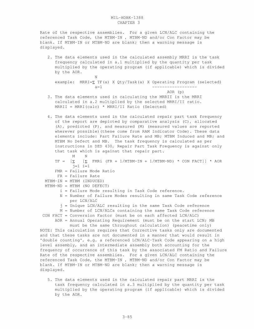
CHAPTER 3MIL-HDBK-1388
3-85
Rate of the respective assemblies. For a given LCN/ALC containing the referenced Task Code, the MTBM-IN , MTBM-ND and/or Con Factor may be blank. If MTBM-IN or MTBM-ND are blank; then a warning message is displayed.
2. The data elements used in the calculated assembly MRRI is the task frequency calculated in a.1 multiplied by the quantity per task multiplied by the operating program (if applicable) which is divided by the AOR. N example: MRRI=� TF(a) X Qty/Task(a) X Operating Program (selected) a=1 ------------------ AOR (p) 3. The data elements used in calculating the MRRII is the MRRI calculated in a.2 multiplied by the selected MRRI/II ratio. MRRII = MRRI(calc) * MRRI/II Ratio (Selected)
4. The data elements used in the calculated repair part task frequency of the report are depicted by comparative analysis (C), allocated (A), predicted (P), and measured (M) (measured values are reported wherever possible)(these come from RAM Indicator Code). These data elements include: Part Failure Rate and MB; MTBM Induced and MB; and MTBM No Defect and MB. The task frequency is calculated as per instructions in DED 430, Repair Part Task Frequency is against only that task which is against that repair part. M N TF = [� [� FMRi (FR + 1/MTBM-IN + 1/MTBM-ND) * CON FACT]] * AOR j=1 i=1 FMR = Failure Mode Ratio FR = Failure Rate MTBM-IN = MTBM (INDUCED) MTBM-ND = MTBM (NO DEFECT) i = Failure Mode resulting in Task Code reference. N = Number of Failure Modes resulting in same Task Code reference per LCN/ALC j = Unique LCN/ALC resulting in the same Task Code reference M = Number of LCN/ALCs containing the same Task Code reference CON FACT = Conversion Factor (must be on each affected LCN/ALC) AOR = Annual Operating Requirement (must be on the start LCN; MB must be the same throughout calculation) (peacetime only) NOTE: This calculation requires that Corrective tasks only are documented and that these tasks are not documented in a manner that would result in "double counting", e.g. a referenced LCN/ALC-Task Code appearing on a high level assembly, and an intermediate assembly both accounting for the frequency of occurrence of this task by the associated FM Ratio and Failure Rate of the respective assemblies. For a given LCN/ALC containing the referenced Task Code, the MTBM-IN , MTBM-ND and/or Con Factor may be blank. If MTBM-IN or MTBM-ND are blank; then a warning message is displayed.
5. The data elements used in the calculated repair part MRRI is the task frequency calculated in a.3 multiplied by the quantity per task multiplied by the operating program (if applicable) which is divided by the AOR.

CHAPTER 3MIL-HDBK-1388
3-86
N example: MRRI=� TF(rp)X Qty/Task(rp) X Operating Program (selected) rp=1 ------------------ AOR (p) 6. The data elements used in calculating the MRRII is the MRRI calculated in a.5 multiplied by the selected MRRI/II ratio. MRRII = MRRI(calc) * MRRI/II Ratio (Selected)
30.24.3 REPORT FORMAT. See Figure 3.21
30.24.4 REPORT SEQUENCE. The report is sequenced by ascending values of LCNfor a given Task Code, then ascending task code. This hold true for theAssembly LCN, Repair Part LCN, and Task LCN. For the RAM LCNs they are sequenced in ascending values, then by FMIs.
30.24.5 DATA SOURCES. The source of the data appearing on the LSA-027summary is depicted below by data table and element codes.
Report Header Table Codes Ded Element Code EIAC XB 096 EIACODXA LCN NOMENCLATURE XB 201 LCNAMEXB START LCN XB 199 LSACONXB ALC XB 019 ALTLCNXB TYPE XB 203 LCNTYPXB UOC XC 501 UOCSEIXCUOC is matched VIA the XF Table STOP LCN XB 199 LSACONXB SERVICE DESIGNATOR (Selected)match on the 4th position of the task code BH 427 TASKCDCA OPERATING PROGRAM (SELECTED) OP MB (SELECTED MUST MATCH AOR MB) MRRI/II RATIO (SELECTED)______________________________________________________________________________1 IND LCN (ITEM BEING REPAIRED) BH 199 LSACONBH (LCN IS BASED ON corrective TASK code) BH 427 TASKCDBH TASK TYPE BH 433 TATYPEBH ALC BH 019 ALTLCNBH LCN NOMENCLATURE XB 201 LCNAMEXB AOR (peacetime only) AG 023 ANOPREAG MB AG 238 MEASBSAG SMR CODE HG 389 SMRCODHG MRR MOD HG 213 MRRMODHG WEAROUT LIFE BA 505 WEOULIBA MB BA 238 WOLIMBBA______________________________________________________________________________2 IND LIST ALL REPAIR PARTS FOR "H" R&R TASK, VIA B/CA/CI THAT QUALIFY ON ICC="X" IN HG TABLE
LCN (FOR H TASKS AND X ICC’S) CI 199 PROLCNCI CHECK HG ICC HG 177 ITMCATHG ALC CI 019 PROALCCI ITEM NAME HA 182 ITNAMEHA

CHAPTER 3MIL-HDBK-1388
3-87
REFERENCE NUMBER HA 337 REFNUMHA CAGE HA 046 CAGECDXH SMR CODE HG 389 SMRCODHG MRR MOD HG 213 MRRMODHG______________________________________________________________________________2a IND LIST ALL MRRI AND II’S AGAINST THE LCN/REF NO/CAGE FROM HG FOR ALL 2 IND’S (IN SAME ORDER AS 2 IND’S) TABLE HG (HEADER) MRRI HG 211 MRRONEHG MRRII HG 212 MRRTWOHG LIST THE CALCULATED MRRI AND MRRII FOR THE APPLICABLE CI REPAIR PARTS CALCULATED (HEADER) MRRI (CALCULATED BY ADP SYSTEM) CALCULATED TASK FREQUENCY (CALCULATED) MB (TAKEN FROM CALCULATIONS) QTY/TASK CI 319 PQTYKCI OPERATING PROGRAM (SELECTED) OP MB (SELECTED MUST MATCH AOR MB) MRRII (CALCULATED BY ADP SYSTEM) MRRI (CALCULATED BY ADP SYSTEM) MRRI/II RATIO (SELECTED)______________________________________________________________________________3 INDLIST THE FIRST H TASK AND ITS TABLE AND CALCULATED TASK FREQUENCY. THETASK FREQUENCY IS FOR THE SPECIFIC TASK. THE CALC TASK FREQUENCY IS BASED ONTHE AFFECTED LCNS FROM THE 5 IND. LCN BH 199 TLSACNBH (LCN IS BASED ON CORRECTIVE TASK CODE) BH 427 TASKCDBH ALC BH 019 TALCNCBH TASK CODE BH 427 TTASKCBH TABLE CA TASK FREQ CA 430 TSKFRQCA MB CA 238 AORMSBCA CALCULATED TASK FREQ (CALCULATED) MB (TAKEN FROM CALCULATIONS) FAILURE MODE RATIO BF 136 FMRATOBF FAILURE RATE BD 140 FAILRTBD MB BD 238 FARAMBBD RAM I C BD 347 RAMINDBD MTBM INDUCED BD 231 INMTBMBD MB BD 281 IMTBMMBD MTBM NO DEFECT BD 233 NOMTBMBD MB BD 238 NMTBMMBD CONV FACT BA 059 CONVFABA AOR AG 023 ANOPREAG MB AG 238 MEASBSAG______________________________________________________________________________4 INDLIST ALL QUALIFYING CI’S PROVISIONING PARTS THAT ARE USED FOR THIS TASKCODE USE THE TASK LCN AND ALC TO IDENTIFY THE PARTS USED LCN CI 199 TSKLCNCI ALC CI 019 TSKALCCI PRINT THE PROVISIONING PARTS LCN CI 199 PROLCNCI

CHAPTER 3MIL-HDBK-1388
3-88
ALC CI 019 PROALCCI REFERENCE NUMBER CI 337 PROREFCI CAGE CI 046 PROCAGCI QTY/TASK CI 319 PQTYTKCI UM CI 491 PQTKUMCI______________________________________________________________________________5 IND LIST ALL AFFECTED LCN’S & FMI’S FOR THIS "H" TASK LCN BA/BH 199 LSACONXB ALC BA/BH 019 ALTLCNXB FMI BF 134 FAMOINBF FAILURE MODE RATIO BF 136 FMRATOBF FAILURE RATE BD 140 FAILRTBD MB BD 238 FARAMBBD RAM I C BD 347 RAMINDBD MTBM INDUCED BD 231 INMTBMBD MB BD 238 IMTBMMBD MTBM NO DEFECT BD 233 NOMTBMBD MB BD 238 NMTBMMBD CONV FACT BA 059 CONVFABA______________________________________________________________________________REPEAT THIS PROCESS FOR THE NEXT "H" TASK FOR THIS LCN____________________________________________________________________________2 IND LIST ALL REPAIR PARTS FOR "J" REPAIR TASK, VIA B/CA/CI THAT QUALIFY ON ICC="Y" IN HG TABLE LCN (FOR H TASKS AND Y ICC’S) CI 199 PROLCNCI CHECK HG ICC HG 177 ITMCATHG ALC CI 019 PROALCCI ITEM NAME HA 182 ITNAMEHA REFERENCE NUMBER HA 337 REFNUMHA CAGE HA 046 CAGECDXH SMR CODE HG 389 SMRCODHG MRR MOD HG 213 MRRMODHG______________________________________________________________________________2a IND LIST ALL MRRI AND II’S AGAINST THE LCN/REF NO/CAGE FROM HG FOR ALL 2 IND’S (IN SAME ORDER AS 2 IND’S) TABLE HG (HEADER) MRRI HG 211 MRRONEHG MRRII HG 212 MRRTWOHG LIST THE CALCULATED MRRI AND MRRII FOR THE APPLICABLE CI REPAIR PARTS CALCULATED (HEADER) MRRI (CALCULATED BY ADP SYSTEM) CALCULATED TASK FREQUENCY (CALCULATED) MB (TAKEN FROM CALCULATIONS) QTY/TASK CI 319 PQTYKCI OPERATING PROGRAM (SELECTED) OP MB (SELECTED MUST MATCH AOR MB) MRRII (CALCULATED BY ADP SYSTEM) MRRI (CALCULATED BY ADP SYSTEM) MRRI/II RATIO (SELECTED)______________________________________________________________________________3 IND

CHAPTER 3MIL-HDBK-1388
3-89
LIST THE FIRST J TASK AND ITS TABLE AND CALCULATED TASK FREQUENCY. THE TASK FREQUENCY IS FOR THE SPECIFIC TASK. THE CALC TASK FREQUENCY IS BASED ON THE AFFECTED LCNS FROM THE 5 IND. LCN BH 199 TLSACNBH (LCN IS BASED ON CORRECTIVE TASK CODE) BH 427 TASKCDBH ALC BH 019 TALCNCBH TASK CODE BH 427 TTASKCBH TABLE CA TASK FREQ CA 430 TSKFRQCA MB CA 238 AORMSBCA CALCULATED TASK FREQ (CALCULATED) MB (TAKEN FROM CALCULATIONS) FAILURE MODE RATIO BF 136 FMRATOBF FAILURE RATE BD 140 FAILRTBD MB BD 238 FARAMBBD RAM I C BD 347 RAMINDBD MTBM INDUCED BD 231 INMTBMBD MB BD 281 IMTBMMBD MTBM NO DEFECT BD 233 NOMTBMBD MB BD 238 NMTBMMBD CONV FACT BA 059 CONVFABA AOR AG 023 ANOPREAG MB AG 238 MEASBSAG______________________________________________________________________________4 INDLIST ALL QUALIFYING CI’S PROVISIONING PARTS THAT ARE USED FOR THIS TASK CODEUSE THE TASK LCN AND ALC TO IDENTIFY THE PARTS USED LCN CI 199 TSKLCNCI ALC CI 019 TSKALCCI PRINT THE PROVISIONING PARTS LCN CI 199 PROLCNCI ALC CI 019 PROALCCI REFERENCE NUMBER CI 337 PROREFCI CAGE CI 046 PROCAGCI QTY/TASK CI 319 PQTYTKCI UM CI 491 PQTKUMCI______________________________________________________________________________5 INDLIST ALL AFFECTED LCN’S & FMI’S FOR THIS "J" TASK
LCN BA/BH 199 LSACONXB ALC BA/BH 019 ALTLCNXB FMI BF 134 FAMOINBF FAILURE MODE RATIO BF 136 FMRATOBF FAILURE RATE BD 140 FAILRTBD MB BD 238 FARAMBBD RAM I C BD 347 RAMINDBD MTBM INDUCED BD 231 INMTBMBD MB BD 238 IMTBMMBD MTBM NO DEFECT BD 233 NOMTBMBD MB BD 238 NMTBMMBD CONV FACT BA 059 CONVFABA______________________________________________________________________________REPEAT THIS PROCESS FOR THE NEXT "J" TASK FOR THIS LCN______________________________________________________________________________

CHAPTER 3MIL-HDBK-1388
3-90
LSA-027
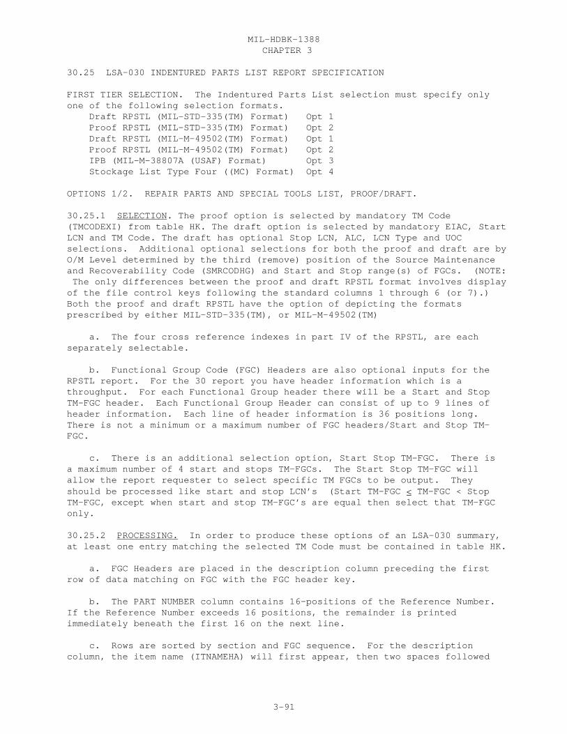
CHAPTER 3MIL-HDBK-1388
3-91
30.25 LSA-030 INDENTURED PARTS LIST REPORT SPECIFICATION
FIRST TIER SELECTION. The Indentured Parts List selection must specify onlyone of the following selection formats. Draft RPSTL (MIL-STD-335(TM) Format) Opt 1 Proof RPSTL (MIL-STD-335(TM) Format) Opt 2 Draft RPSTL (MIL-M-49502(TM) Format) Opt 1 Proof RPSTL (MIL-M-49502(TM) Format) Opt 2 IPB (MIL-M-38807A (USAF) Format) Opt 3 Stockage List Type Four ((MC) Format) Opt 4
OPTIONS 1/2. REPAIR PARTS AND SPECIAL TOOLS LIST, PROOF/DRAFT.
30.25.1 SELECTION. The proof option is selected by mandatory TM Code(TMCODEXI) from table HK. The draft option is selected by mandatory EIAC, StartLCN and TM Code. The draft has optional Stop LCN, ALC, LCN Type and UOCselections. Additional optional selections for both the proof and draft are byO/M Level determined by the third (remove) position of the Source Maintenanceand Recoverability Code (SMRCODHG) and Start and Stop range(s) of FGCs. (NOTE: The only differences between the proof and draft RPSTL format involves displayof the file control keys following the standard columns 1 through 6 (or 7).) Both the proof and draft RPSTL have the option of depicting the formatsprescribed by either MIL-STD-335(TM), or MIL-M-49502(TM)
a. The four cross reference indexes in part IV of the RPSTL, are eachseparately selectable.
b. Functional Group Code (FGC) Headers are also optional inputs for theRPSTL report. For the 30 report you have header information which is athroughput. For each Functional Group header there will be a Start and StopTM-FGC header. Each Functional Group Header can consist of up to 9 lines ofheader information. Each line of header information is 36 positions long.There is not a minimum or a maximum number of FGC headers/Start and Stop TM-FGC.
c. There is an additional selection option, Start Stop TM-FGC. There isa maximum number of 4 start and stops TM-FGCs. The Start Stop TM-FGC willallow the report requester to select specific TM FGCs to be output. Theyshould be processed like start and stop LCN’s (Start TM-FGC � TM-FGC < StopTM-FGC, except when start and stop TM-FGC’s are equal then select that TM-FGConly.
30.25.2 PROCESSING. In order to produce these options of an LSA-030 summary,at least one entry matching the selected TM Code must be contained in table HK.
a. FGC Headers are placed in the description column preceding the firstrow of data matching on FGC with the FGC header key.
b. The PART NUMBER column contains 16-positions of the Reference Number.If the Reference Number exceeds 16 positions, the remainder is printedimmediately beneath the first 16 on the next line.
c. Rows are sorted by section and FGC sequence. For the descriptioncolumn, the item name (ITNAMEHA) will first appear, then two spaces followed
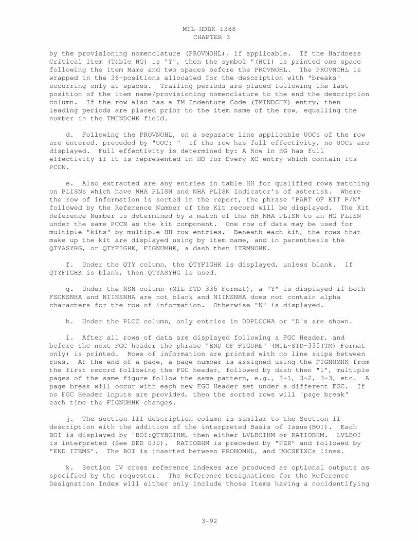
CHAPTER 3MIL-HDBK-1388
3-92
by the provisioning nomenclature (PROVNOHL), if applicable. If the HardnessCritical Item (Table HG) is "Y", then the symbol "(HCI) is printed one spacefollowing the Item Name and two spaces before the PROVNOHL. The PROVNOHL iswrapped in the 36-positions allocated for the description with "breaks"occurring only at spaces. Trailing periods are placed following the lastposition of the item name/provisioning nomenclature to the end the descriptioncolumn. If the row also has a TM Indenture Code (TMINDCHK) entry, thenleading periods are placed prior to the item name of the row, equalling thenumber in the TMINDCHK field.
d. Following the PROVNOHL, on a separate line applicable UOCs of the roware entered. preceded by "UOC: " If the row has full effectivity, no UOCs aredisplayed. Full effectivity is determined by: A Row in HG has fulleffectivity if it is represented in HO for Every XC entry which contain itsPCCN.
e. Also extracted are any entries in table HH for qualified rows matchingon PLISNs which have NHA PLISN and NHA PLISN Indicator’s of asterisk. Wherethe row of information is sorted in the report, the phrase "PART OF KIT P/N"followed by the Reference Number of the Kit record will be displayed. The KitReference Number is determined by a match of the HH NHA PLISN to an HG PLISNunder the same PCCN as the kit component. One row of data may be used formultiple "kits" by multiple HH row entries. Beneath each kit, the rows thatmake up the kit are displayed using by item name, and in parenthesis theQTYASYHG, or QTYFIGHK, FIGNUMHK, a dash then ITEMNOHK.
f. Under the QTY column, the QTYFIGHK is displayed, unless blank. IfQTYFIGHK is blank, then QTYASYHG is used.
g. Under the NSN column (MIL-STD-335 Format), a "Y" is displayed if bothFSCNSNHA and NIINSNHA are not blank and NIINSNHA does not contain alphacharacters for the row of information. Otherwise "N" is displayed.
h. Under the PLCC column, only entries in DDPLCCHA or "D"s are shown.
i. After all rows of data are displayed following a FGC Header, andbefore the next FGC header the phrase "END OF FIGURE" (MIL-STD-335(TM) Formatonly) is printed. Rows of information are printed with no line skips betweenrows. At the end of a page, a page number is assigned using the FIGNUMHK fromthe first record following the FGC header, followed by dash then "1", multiplepages of the same figure follow the same pattern, e.g., 3-1, 3-2, 3-3, etc. Apage break will occur with each new FGC Header set under a different FGC. Ifno FGC Header inputs are provided, then the sorted rows will "page break"each time the FIGNUMHK changes.
j. The section III description column is similar to the Section IIdescription with the addition of the interpreted Basis of Issue(BOI). EachBOI is displayed by "BOI:QTYBOIHM, then either LVLBOIHM or RATIOBHM. LVLBOIis interpreted (See DED 030). RATIOBHM is preceded by "PER" and followed by"END ITEMS". The BOI is inserted between PRONOMHL, and UOCSEIXCs lines.
k. Section IV cross reference indexes are produced as optional outputs asspecified by the requester. The Reference Designations for the ReferenceDesignation Index will either only include those items having a nonidentifying

CHAPTER 3MIL-HDBK-1388
3-93
migrating key of the appropriate Figure Number, Item Number, and TM Code; or ifthese keys are not present, it will include all related Figure Numbers, ItemNumbers, and TM Codes from the HK table for the Reference Designator key set.Overflows of Reference Numbers or Reference Designations exceeding 16 or 32positions, respectively are printed on the next line immediately below thefirst portion of the element.
l. Suppression rules for section IV part number indexes and figure anditem number indexes. Part number index suppresses any additional row ofinformation if the CAGE, Part Number, Stock Number, Figure Number and ItemNumbers are the same. Part number index also suppress the CAGE and PartNumber if the figure number and item number are different for the same CAGE,Part Number, and Stock Number. Figure and Item Number Index suppresses anyadditional row of information if the CAGE, Part Number, Stock Number, FigureNumber, and Item Number are the same.
30.25.3 REPORT FORMAT. See Figure 3.22
30.25.4 REPORT SEQUENCE.
a. Sections II and III of the report are primarily sequenced by Section.Section is determined by the Provisioning List Category Code (PLCC). Itemscoded with a PLCC entry in DDPLCCHA are placed in section III. All otheritems are placed in section II. Within section, items are sequenced inascending FGC, followed by item, then PLISN.
b. Part Number Index is sorted in ascending Reference Number, then CAGE.
c. National Stock Number index is sorted in ascending NIIN (NIINSNHA), bycolumn one, then by column two on a given page.
d. Reference Designation Index is sorted in ascending ReferenceDesignation.
e. Figure and Item Number Index is sorted in ascending Figure, then ItemNumbers, then Reference Number.
30.2.5.5 DATA SOURCE. See attached listing.
OPTION 3. ILLUSTRATED PARTS BREAKDOWN.
30.2.5.1 SELECTION. This LSA-030 option is selected by a mandatory TM Code.
30.25.2 PROCESSING. Extracted for the IPB are any entries in table HH forqualified rows matching on PLISNs which have NHA PLISN and NHA PLISNIndicator’s of asterisk. Where the row of information is sorted in the report,the phrase "PART OF KIT P/N" followed by the Reference Number of the Kit recordwill be displayed. The Kit Reference Number is determined by a match of the HHNHA PLISN to an HG PLISN under the same PCCN as the kit component. One row ofdata may be used for multiple "kits" by multiple HH row entries. Beneath eachkit, the rows that make up the kit are displayed using by item name, and inparenthesis the QTYASYHG, or QTYFIGHK, FIGNUMHK, a dash then ITEMNOHK.
a. A separate column for applicable UOCs of the row are entered. If the
CHAPTER 3MIL-HDBK-1388
3-94
row has full effectivity, no UOCs are displayed. Full effectivity isdetermined by table HO/XC applicability of the as the row of information toall XC UOC matching on the row PCCN.
b. If the Hardness Critical Item (Table HG) is "Y", then the symbol"(HCI) is printed prior to the Item Name.
c. The Provisioning Nomenclature is displayed with two spaces between itand the last completed position of the Item Name. Provisioning Nomenclaturewill break only on spaces between lines. On the second and subsequent linesof Nomenclature automatically assigned two leading periods (e.g., .., ) willprecede the nomenclature continuation. Trailer points shall be printed to"fill" the description column blank spaces from the last nomenclaturecharacter to the end of the description field. On subsequent lines for thesame item, the trailer points are not used. Subsequent column data isdisplayed in line with the first description row.
d. An item will contain leading periods equal to the entry against theitem’s TM Indenture Code (1-5). The Numbers 12345 are displayed in the firstfive positions of the Description column.
30.25.3 REPORT FORMAT. See Figure 3.22
30.2.5.4 REPORT SEQUENCE. Section II is sequenced in ascending Figure andItem Number; III is sequenced by ascending Reference Number; and IV inascending Reference Designation.
30.2.5.5 DATA SOURCE. See attached listing.
OPTION 4. STOCKAGE LIST TYPE FOUR.
30.25.1 SELECTION. This LSA-030 option is selected by mandatory START LCN.Optional selection entries are ALC, STOP LCN, and UOC. A selection throughputis a 20-position SL number.
30.25.2 PROCESSING.
a. Item identification (column 6) consists of the Item Name (ITNAMEHA)
b. Reference Designation (column 4) is truncated after 8 positions. Onlya Reference Designation with an RDC of "F" is extracted for the LSA-030. Ifmultiple "F" Reference Designations are documented in the HJ table for anitem, these are used to make up multiple rows of the summary.
c. Column 8, QUANTITY APPL is QPA; PER EQUIP is the QPEI. If REF or REFXis entered in the QPEI, then this is suppressed on the output report.
d. Print all matched UOC’s (XC/HO) if no UOC is Selected. If there areextra UOC’s they should be printed under the model header, under theappropriate item number line
e. The TM Codes and Fig Numbers are pulled from HJ, if there isn’t amatch in HJ, then pull all HK table TM Codes and Fig Numbers against the HJLCN Keys and HJ Ref No keys matched in the HK table.
CHAPTER 3MIL-HDBK-1388
3-95
f. Terms used on the LSA-030 summary:
(1) Reference Designation (Figure Key) (REF DESIG FIG-KEY). ReferenceDesignation with an associated Reference Designation Code of "F" (first eight-positions only).
(2) Special Stockage Indicator (SSI) Assigned by the requiring authority,the SSI is left blank by the preparing activity.
(3) Replacement Factor (REPL FACTOR). Maintenance Replacement Rate I ,fourth through seventh positions only.
30.25.3 REPORT FORMAT. See Figure 3.22
30.25.4. REPORT SEQUENCE. The report sorts on ascending Reference Designationand LCN sequence. A Reference Designation ending in an alpha character issorted in sequence of the closest numeric, e.g.,012-0005, 012-005A, 012-0006.
30.25.5 DATA SOURCE. The source of data appearing on the LSA-030 summary isdepicted below by data table and element codes.
OPTION 1-3, RPSTL DRAFT/PROOF AND IPB.
Report header Table Code DED Element Code
EIAC HG 096 EIACODXA ITEM NAME HA 182 ITNAMEHA START LCN HG 199 LSACONXB ALC HG 019 ALTLCNXB LCN TYPE HG 203 LCNTYPXB UOC HO/XC 501 UOCSEIXC STOP LCN HG 199 LSACONXB TM CODE HK 437 TMCODEXI TM DESIGNATION XI 440 TMNUMBXI OPERATIONS/MAINTENANCE LEVELS: HG 389 SMRCODHG START/STOP FGC RANGES HK 438 TMFGCDHK CROSS REFERENCE INDEXES (SELECTED) RPSTL FUNCTIONAL GROUP CODE HEADERS (THROUGHPUT)
SECTION II ITEM NO HK 184 ITEMNOHK SMR HG 389 SMRCODHG CAGE HK 046 CAGECDXH PART NUMBER HK 337 REFNUMHA DESCRIPTION AND USABLE ON CODE (UOC) HA 182 ITNAMEHA HL 310 PROVNOHL HO/XC 501 UOCSEIXC HK 439 TMINDCHK (KIT COMPONENTS) HH 258 NHAPLIHH HH 259 NHAINDHH QTY HG 316 QTYASYHG HK 318 QTYFIGHK FIG NO (draft MIL-STD-335 only) HK 144 FIGNUMHK
CHAPTER 3MIL-HDBK-1388
3-96
FGC (draft MIL-STD-335 only) HK 438 TMFGCDHK PLCC (draft MIL-STD-335 only) HA 308 DDPLCCHA NSN ("Y" in 335, Comp NSN in MIL-M) HA 253 FSCNSNHA HA 253 NIINSNHA PCCN XC 307 PCCNUMXC PLISN HG 309 PLISNOHG
SECTION III DESCRIPTION AND USABLE ON CODE (BASIS OF ISSUE) RPSTL only. HM 030 BOICTRHM HM 030 QTYBOIHM HM 030 RATIOBHM HM 030 LVLBOIHM
SECTION IV STOCK NUMBER HA 253 FSCNSNHA HA 253 NIINSNHA REFERENCE DESIGNATION HJ 335 REFDESHJ FIGURE NO HK 144 FIGNUMHK
OPTION 4. STOCKAGE LIST TYPE FOUR
Report header Table Code DED Element Code EIAC HG 096 EIACODXA ITEM NAME HA 182 ITNAMEHA START LCN HG 199 LSACONXB ALC HG 019 ALTLCNXB LCN TYPE HG 203 LCNTYPXB UOC HO/XC 501 UOCSEIXC STOP LCN HG 199 LSACONXB STOCK LIST NUMBER (SELECTED)
PART I ITEM NO (GENERATED) MODEL HO/XC 501 UOCSEIXC NSN HA 253 FSCNSNHA HA 253 NIINSNHA REF DESIG FIG-KEY HJ 335 REFDESHJ [RDC] HJ 336 RDCODEHJ IND HG 162 INDCODHG ITEM IDENTIFICATION HA 182 ITNAMEHA UM HA 491 UNITMSHA QUANTITY PER APPL HG 316 QTYASYHG XC 316 QTYASYXC PER EQUIP HG 317 QTYPEIHG XC 317 QTYPEIXC SMR CODE HG 389 SMRCODHG SSI (MANUAL) REPL FACTOR HG 211 MRRONEHG CAGE HK 046 CAGECDXH REFERENCE NUMBER HK 337 REFNUMHA TM CODE HJ/HK 437 TMCODEXI FIG NO HJ/HK 144 FIGNUMHK
CHAPTER 3MIL-HDBK-1388
3-97
LSA-030

CHAPTER 3MIL-HDBK-1388
3-98

CHAPTER 3MIL-HDBK-1388
3-99

CHAPTER 3MIL-HDBK-1388
3-100

CHAPTER 3MIL-HDBK-1388
3-101
30.26 LSA-032 DEFENSE LOGISTICS SERVICES CENTER (DLSC) SUBMITTALS PROVISIONING SCREENING REPORT SPECIFICATION
30.26.1 SELECTION. The LSA-032 summary is selected by mandatory START LCN orPCCN, SERV DES, ACTIVITY CODE, DESTINATION CODE, OUT DATA REQ CODE, SGL/MULTOUT CODE, TYPE SCREEN CODE, STAT IND CODE, PRI IND CODE and JULIAN DATE; andoptional ALC, STOP LCN, UOC, SOURCE CODE, ARN SEL CODE, DIC SUPPRESS,DSRC SUPPRESS, and DLSC tape.
30.26.2 PROCESSING. This report may be selected by LCN or PCCN, or Both. Atleast one qualified Reference Number/CAGE combination must exist between theLCN range or be under the PCCN selected in order to produce an LSA-032summary. When selected by LCN range this report may have items from multiplePCCNs. The TAPE option results in an 80-column file of part II information.The report is processed as follows:
a. Items may be excluded from the report by already having a screeningresult displayed in the DIC field. This means that if suppression isselected, any item that has a DIC code in the database will not be screenedagain, and therefore, not output on the report. Items may also be excludedfrom the report by having a result in DLIS Screening Result Code (DSRC). TheADP system should allow suppression of up to five codes, A, B, C, D, and E.If an item contains one of these codes, i.e. "A", and "A" is selected to besuppressed on the selection card, then any item having an "A" DSRC will notcome out on the report.
b. Part of the submitter control number is the PCCN/PLISN. The PLISNused is the lowest EBCDIC valued PLISN for the item within the selectedPCCN/LCN range (the Same As PLISN field is blank). If no PCCN/PLISN isrecorded for an item, then a Type "1" error is displayed. No rows of data forthe item are placed on part II.
c. If Additional Reference Number Select (ARN SEL) is "YES" and if theitem has more than 24 additional reference numbers, then error Type "2" isdisplayed. The first 24 ARNs in ascending reference number sequence areplaced on part II of the report.
d. If a specific SOURCE CODE is selected and the SMR is not containedagainst an item, at its first appearance, then error Type "3" is shown and theitem is disqualified from part II. The source code may be selected by itsfirst position only in which case all corresponding second positions wouldqualify. For example, if you select "P" source code, that would qualify "PA","PB", "PC","PD","PE","PF", and "PG" source codes.
e. If TYPE SCREEN CODE is "F" or "S", and if ARN SEL is "YES" and if anAdditional Reference Number matches the prime Reference Number, then errortype "4" is displayed. Only the duplicate ARN is disqualified from part II.In part II of the report, columns 41 and 42 are always left blank for "F" or"S" type screen.
f. If TYPE SCREEN CODE is "P", and if either the reference numbercategory code (RNCC) or reference number variation code (RNVC) is missing forthe reference number/CAGE (in HA) or if ARN SEL is "YES" and there are anyadditional reference number and CAGE (in HB), then error Type "5" is

CHAPTER 3MIL-HDBK-1388
3-102
displayed. If the RNCC/RNVC is an ARN, only the ARN is disqualified from partII. If the RNCC/RNVC is the prime reference number, then the entire item isdisqualified from Part II.
Definitions of LSA-032 report selection entries:
a. Document Identifier Code (DIC) - A three-position alphanumeric codewhich is used for identifying interservice agency or intraservice agencylogistic transactions. On part II of this report the DIC will always be "LSR"signifying Reference Number and CAGE screening requests. Items may beexcluded from DLSC screening, if an entry showing a screening result, isalready contained in the DIC field for the Reference Number and CAGE.
b. Priority Indicator Code (PIC) - A single numeric code used todesignate the required priority to be applied to processing transactions. SeeDOD4l00.38-M.
c. Activity Code (ACT CD) - A two-position alpha code identifying a DODactivity, Federal agency or other authorized Government agency for cataloging,standardization or other management purposes. See DOD 4l00.38-M.
d. Destination Code (DEST CD) - A five-position alphanumeric code used inconjunction with the activity code to register the address data for recipientsof the results of provisioning screening. See DOD 4l00.38-M.
e. Output Data Request Code (ODRC) - A numeric series of established setsof data (DID output segments) identified by specific ODRC‘s and available forextraction from DLSC files for provisioning and preprocurement screeningpurposes. See DOD 4l00.38-M.
f. Single/Multiple Output Code - A numeric code used by the submitter toindicate whether the results of screening are to be furnished to one or all ofthe recipients as registered under the applicable activity code anddestination code. See DOD 4l00.38-M.
g. Submitter‘s Control Number (SUB CONT NO) - A seventeen-positioncomputer assigned alphanumeric field peculiar to provisioning andpreprocurement screening transactions which is used to control and referencethe transactions. The number consists of a four position julian date (YDDD),and a unique sequential 13 position number assigned for each reference numberand additional reference number package which is to be screened. Thisconsists of the selection Service Designator Code, PCCN, then PLISN.
h. Statistical Indicator Code. A code designating whether data submittedfor screening is requiring for provisioning or other services. See DOD4100.38-M.
i. DIDS segment code. This is the number of inputs segments that arerequired by DILS for each record. This should always be a "2" to represent afixed length record LSR (DIC) submittal.
j. Package Sequence Number (PSN). The PSN is a three-character code usedto indicate the quantity, sequence and interrelationship of cards related to aline item as within a package (i.e. applies to the same submitter’s control

CHAPTER 3MIL-HDBK-1388
3-103
number). If all line items submitted for screening are individually sequencein the submitters control number field, the PSN will always be "Z01". Forreference number screening (DIC of "LSR") a maximum of 25 reference numbers maybe submitted under the same SCN. In this instance the first record would havea PSN of "A01", the second "A02", the third "A03", etc, through "A24", and thelast (25th) record would be "Z25". The last record in any package submittedunder one SCN will always contain a "Z" in the first position of the PSN. 30.26.3 REPORT FORMAT. See Figure 3.23
30.26.4 REPORT SEQUENCE. The Report is sequenced in ascending SubmitterControl Number. On the first line is information about the Prime ReferenceNumber and the item’s LCN/ALC and SMR of the first appearance. Within thisitem are listed all additional reference numbers in ascending ARN sequence.
30.26.5 DATA SOURCE. The source of data appearing on the LSA-032 summary isdepicted below by data table and element codes.
Report header Table Code DED Element Code EIAC HG 096 EIACODXA ITEM NAME HA 182 ITNAMEHA START LCN HG 199 LSACONXB ALC HG 019 ALTLCNXB LCN TYPE HG 203 LCNTYPXB STOP LCN HG 199 LSACONXB UOC HO/XC 501 UOCSEIXC SERV DES (SELECTED) PCCN HG 307 PCCNUMHG ACTIVITY CODE (SELECTED) DESTINATION CODE (SELECTED) OUT DATA REQ CODE (SELECTED) SGL/MULT OUT CODE (SELECTED) SOURCE CODE HG 389 SMRCODHG ARN SEL CODE (SELECTED) TYPE SCREEN CODE (SELECTED) STAT IND CODE (SELECTED) PRI IND CODE (SELECTED) JULIAN DATE (SELECTED) DIC SUPPRESS HA 087 DOCIDCHA DSRC SUPPRESS HA 073 DLSCRCHA DLSC TAPE (SELECTED) SUBMITTER CONTROL (GENERATED) REFERENCE NUMBER/ARN HG 337 REFNUMHA HB 006 ADDREFHB CAGE HG 046 CAGECDXH HB 046 ADCAGEHB RNCC HA 338 REFNCCHA HB 338 ADRNCCHB RNVC HA 339 REFNVCHA HB 339 ADRNVCHB LCN HG 199 LSACONXB ALC HG 019 ALTLCNXB SMR HG 389 SMRCODHG ERROR CODES(S) (GENERATED)

CHAPTER 3MIL-HDBK-1388
3-104
LSA-032
CHAPTER 3MIL-HDBK-1388
3-105
30.27 LSA-033 PREVENTIVE MAINTENANCE CHECKS AND SERVICES REPORT SPECIFICATION
30.27.1 SELECTION. The LSA-033 summary is selected by mandatory EIAC, STARTLCN and LCN TYPE. Optional selection items are ALC (default is all ALC’s),STOP LCN (default is all LCNs subordinate to, and including, the start LCN),UOC (default is all UOCs), TM CODE (default is all TM Codes), TM Number(default is all applicable TM Numbers), and SERV DES (default is all ServiceDesignators).
30.27.2 PROCESSING. Within the selected range of LCNs/TM Code Tasks, at leastone task code must be present with a PMCS Indicator (PMCSIDCA) of "Y" in orderto produce an LSA-033 summary. All PM tasks must have a PMCS Indicator of "Y"and have a "C" or "O" in the 3rd position of the task Code to be printed onthis output. If TM Code is selected you should check in the CH table to makesure the task is used in the selected TM.Item Numbers (ITEM NO.) are assignedbeginning with 0001 and increase incrementally by 1 as with each new LCN. TheLCN Nomenclature is displayed under the column ITEMS TO CHECK/SERVICE
a. Task Interval values are interpreted as follows: A, BEFORE, D,DURING; H, AFTER; C, DAILY; L, WEEKLY; P, MONTHLY; M, QUARTERLY; N,SEMIANNUALLY; Q, YEARLY, Maintenance interval, and asterisk. If the intervalis "B" then the B table Maintenance Interval (208) and Measurement Base (238)are displayed under the INTERVAL column. The measurement base is interpretedon the report, e.g., S, ROUNDS. If the report is selected by TM Code, tasksare qualified to the PMCS report by an associated PMCS indicator (Table CA).If the report is selected by LCN range, tasks are further qualified bymaintenance level (Task Code third position) of Crew or Organizational). Ifmore then one B FMI/MPC reference the same PMCS Task Code, then the Highestnumeric value Maintenance Interval is documented, the MB must be the same, thenthe MB is interpreted, and an asterisk (*) is placed following the MB. If theMB are different then print the highest Maintenance Interval for each MB. Ifthe task interval is other than those listed above or there is no associated Bmaintenance interval, then the Interval column is completely filled withasterisks.
b. If there are multiple qualified PMCS task Codes within a LCN anincremental alphabetic character is assigned prior to displaying allapplicable subtask narrative. If a PMCS task has a Task Remark, this isdisplayed under NOT FULLY MISSION CAPABLE IF: column, directly across from thebeginning of the subtask narrative. If this information is exceeds 30positions, it is carried to the next line of the report breaking the narrativeat a space.
30.27.3 REPORT FORMAT. See Figure 3.24
30.27.4 REPORT SEQUENCE. The report is sorted in ascending Task Code Intervalin the order shown in paragraph 2a above, then by ascending LCN. Each LCN isassigned a numeric item number beginning with "0001" (a new item number isassigned if an LCN appears twice, under two qualified tasks with differentintervals). An alphabetic sequence code beginning with "A" is assigned to eachTask for the same LCN with the same Task Code Interval. If the report isselected by LCN range and TM Code, a page break is required between output ofOperator/ Crew level PMCS tasks and Organizational level PMCS tasks.
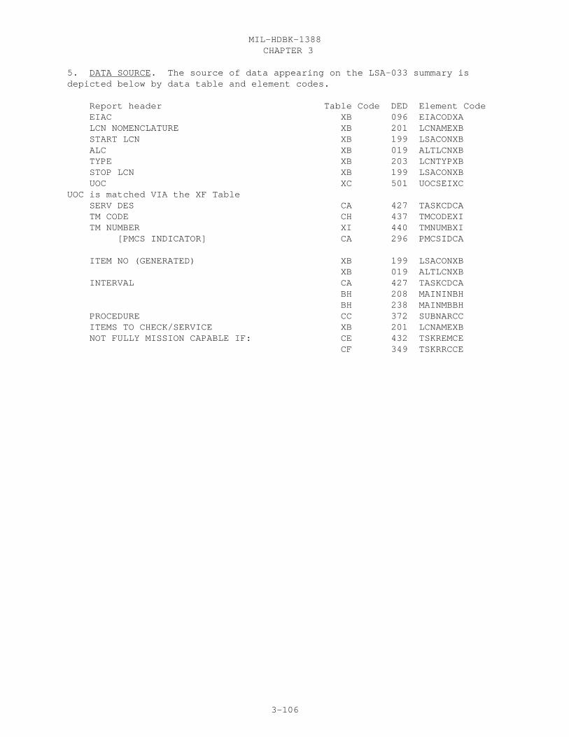
CHAPTER 3MIL-HDBK-1388
3-106
5. DATA SOURCE. The source of data appearing on the LSA-033 summary isdepicted below by data table and element codes. Report header Table Code DED Element Code EIAC XB 096 EIACODXA LCN NOMENCLATURE XB 201 LCNAMEXB START LCN XB 199 LSACONXB ALC XB 019 ALTLCNXB TYPE XB 203 LCNTYPXB STOP LCN XB 199 LSACONXB UOC XC 501 UOCSEIXCUOC is matched VIA the XF Table SERV DES CA 427 TASKCDCA TM CODE CH 437 TMCODEXI TM NUMBER XI 440 TMNUMBXI [PMCS INDICATOR] CA 296 PMCSIDCA
ITEM NO (GENERATED) XB 199 LSACONXB XB 019 ALTLCNXB INTERVAL CA 427 TASKCDCA BH 208 MAININBH BH 238 MAINMBBH PROCEDURE CC 372 SUBNARCC ITEMS TO CHECK/SERVICE XB 201 LCNAMEXB NOT FULLY MISSION CAPABLE IF: CE 432 TSKREMCE CF 349 TSKRRCCE

CHAPTER 3MIL-HDBK-1388
3-107
LSA-033

CHAPTER 3MIL-HDBK-1388
3-108
30.28 LSA-036 PROVISIONING REQUIREMENTS REPORT SPECIFICATION
30.28.1 SELECTION. The LSA-036 summary is selected by mandatory PCCN, TYPELIST (PTD SELECTION CODE, DED 313) OUTPUT MODE and UOC(S). Also required forthe LSA-036 request are the PIIN/SPIIN, NOMENCLATURE OF MODEL OR TYPE NUMBER,CONTROL DATA, PRIME CAGE, SUBMITTER CONTROL NO, and SUBMITTAL DATE. Optionalselections are MULTI-CONFIG UOCS ASSIGNED, FULL EFFECTIVITY UOC SUPPRESS,START AND STOP PLISN ranges, PROVISIONING BASELINED, QPEI CALCULATED, OVERHAULPLISNS, and Part III.
30.28.2 PROCESSING. All records matching the selected PCCN are extracted forLSA-036 processing. If the records are disqualified because of no match oneither Type of PTD List or UOCs selected, these are counted for the Headerpage summary and are displayed in the LSA-036, Part II.
a. The following "header" data required to identify the specified list(s)are not a part of the LSAR but are contained in the LSA-036 summary.
(1) Procurement Instrument Identification (PII). A nineteen-position alphanumeric entry used to identify a specific contractual document.The PII includes the procurement instrument identification number (PIIN), (l3positions) and the supplementary procurement instruction identification number(SPIIN) (6 positions).
(2) Nomenclature of model or type number. A twenty-one-positionalphanumeric entry used to specify the name, model, or type of equipment beingprovisioned.
(3) Control Data. A ten-position alphanumeric entry used for con-trol information as specified by the requiring authority. This informationmay consist of such items as identification of provisioning data inMIL-STD-1388-2 format or a Weapons System Code.
(4) Prime Contractor‘s Commercial and Government Entity (CAGE) Code.A five-position alphanumeric entry which identifies the prime contractor forthe equipment being provisioned.
(5) Submission Control Code. A five-position numeric entry used tocontrol the submission of provisioning data. The first submission will be0000l and each subsequent submission is to be numbered sequentially, onegreater than the prior submission.
(6) Date list submitted. A six-position, numeric entry used toidentify the date of submission. The first two positions will identify theyear; the next two will identify the month, and the last two will identify theday.
b. The report will display the following provisioning report controldata:
(1) Card Sequence Number (CSN). A two-position numeric code whichis used to sequence multiple data input cards for a specific card format in-dicator. The initial card entry is coded 0l. Subsequent cards are coded 02-99.
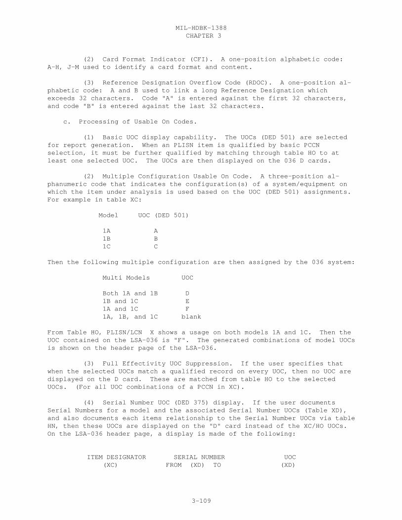
CHAPTER 3MIL-HDBK-1388
3-109
(2) Card Format Indicator (CFI). A one-position alphabetic code:A-H, J-M used to identify a card format and content.
(3) Reference Designation Overflow Code (RDOC). A one-position al-phabetic code: A and B used to link a long Reference Designation whichexceeds 32 characters. Code "A" is entered against the first 32 characters,and code "B" is entered against the last 32 characters.
c. Processing of Usable On Codes.
(1) Basic UOC display capability. The UOCs (DED 501) are selectedfor report generation. When an PLISN item is qualified by basic PCCNselection, it must be further qualified by matching through table HO to atleast one selected UOC. The UOCs are then displayed on the 036 D cards.
(2) Multiple Configuration Usable On Code. A three-position al-phanumeric code that indicates the configuration(s) of a system/equipment onwhich the item under analysis is used based on the UOC (DED 501) assignments.For example in table XC:
Model UOC (DED 501)
1A A 1B B 1C C
Then the following multiple configuration are then assigned by the 036 system:
Multi Models UOC
Both 1A and 1B D 1B and 1C E 1A and 1C F 1A, 1B, and 1C blank
From Table HO, PLISN/LCN X shows a usage on both models 1A and 1C. Then theUOC contained on the LSA-036 is "F". The generated combinations of model UOCsis shown on the header page of the LSA-036.
(3) Full Effectivity UOC Suppression. If the user specifies thatwhen the selected UOCs match a qualified record on every UOC, then no UOC aredisplayed on the D card. These are matched from table HO to the selectedUOCs. (For all UOC combinations of a PCCN in XC).
(4) Serial Number UOC (DED 375) display. If the user documentsSerial Numbers for a model and the associated Serial Number UOCs (Table XD),and also documents each items relationship to the Serial Number UOCs via tableHN, then these UOCs are displayed on the "D" card instead of the XC/HO UOCs.On the LSA-036 header page, a display is made of the following:
ITEM DESIGNATOR SERIAL NUMBER UOC (XC) FROM (XD) TO (XD)

CHAPTER 3MIL-HDBK-1388
3-110
C18 SN001 SN015 A SN017 SN017 B SN062 SN071 C
C18A1 SN016 SN016 E SN018 SN061 F
d. Quantity per End Item (QPEI) (DED 317). The QPEI (three options) maybe computed during the LSA-036 report preparation using the formulas providedin the data definitions. These are displayed on the report and update boththe data tables HG/XC and the baselined provisioning file.
e. Overhaul PLISN (DED 258) and Overhaul Replacement Rate (ORR) DED 281)Assignment. The overhaul PLISNs may be assigned during the LSA-036 reportpreparation based on the item having a P- source code, an ORR entry, andat least one of its higher assembly PLISN having an SMR Code of P--D-. Onlythose higher assembly PLISNs with and SMR code 0f P--D- will be assignedoverhaul PLISNs. The ORR is an estimate of the percent of time that a supportitem will be replaced at the NHA during Overhaul. It is manually entered inthe HH table against its NHA. This base ORR of the item is multiplied by theQPA for each succeeding indenture level, beyond the NHA, using the followingapproach for assignment:
PLISN IC SMR QPA NHA PLISN NHA-IND ORR
CFFF F PADZZ 0002 CEAA N 005 CEAA E PAODD 0002 CDEE N 002 CDEE D PAFDD 0003 CCDD N CCDD C PAOHH 0001 CB12 N 003 CB12 B PAFDD 0002 AAAA E 006 AAAA A PAODD 0001
For PLISN CFFF, the Overhaul PLISNs and associated ORRs are:
OVERHAUL PLISN ORR
CEAA 005 CDEE 015 CB12 030 AAAA 030
NOTE: PLISN CEAA is the items immediate NHA PLISN and therefore nocalculation is needed; and PLISN CCDD is disqualified because it is SMR CodedPAOHH.
f. Same as PLISN (DED 364). The Same as PLISN may be assigned during theLSA-036 summary preparation. These are displayed on the report and updatedata table HG and the baselined provisioning file.
g. LSA-036 Update and Design Change Notices. There are five basic typesof LSA-036 updates which can result when LSAR data is added, changed ordeleted affecting PL‘s previously delivered. These transactions can beautomatically generated using a validated LSAR ADP system by establishing

CHAPTER 3MIL-HDBK-1388
3-111
baseline records upon initial submission of the LSA-036. These transactionsare based upon a comparison of the current LSAR provisioning oriented datatables and provisioning data baselined by a previous LSA-036 submittal.
(1) Standard Data Update. For each LSA-036 card affected by data whichhas been added or changed since the previous PL delivery or LSA-036 update,mandatory data, i.e., PCCN, PLISN, CSN, and CFI, an "M" Type of Change Code(TOCC) and the added/changed data only are entered. If data has been deleted,a "G" is entered in the TOCC and in the left most position of each fielddeleted on the appropriate LSA-036 card. (NOTE: MRR MOD must have allpositions filled with a "G" to be deleted). Data deletions and changes/additions occurring on the same LSA-036 card will require both a change anddeletion card for the appropriate data.
(a) If all data on an LSA-036 CFI is deleted, mandatory data and a"D" TOCC are entered and the data fields are left blank.
(b) When an entire PLISN record is deleted, PCCN, PLISN and "D" TOCCare entered and the CAGE and Reference Number are displayed on the "01A" card.In addition, if any Change Authority related information is changed, CFIs "F""G" and "H" update transactions are also processed.
(2) Quantity Data Update. When a quantity field is updated, mandatorydata, a "Q" TOCC and the updated quantity data field(s) are entered. Thiswill only apply to the following data: Quantity Per Assembly, Quantity PerEnd Item, Total Quantity Recommended, Allowance Item Code Quantity, MinimumReplacement Unit, Recommended Initial System Stock Buy, Recommended MinimumSystem Stock Level, Recommended Tender Load List Quantity, Quantity Shipped,Quantity Procured and Prorated Quantity. When additional data displayed onthe same LSA-036 card also changes during the update, only one change card isentered with TOCC, "Q". When quantity data is deleted, a change card isentered with a zero filled quantity field and TOCC "Q".
(3) Key Data Update. Certain provisioning data are considered key andassociated data elements. These are listed below. Changes to key datarequires the submission of both a delete and change card for the appropriatekey data. The deletion card should contain a "G" TOCC and the original keydata. The change card should contain an "M" TOCC with the new key data andthe applicable associated data. Deletion of key data will result in deletionof the corresponding associated data.
KEY DATA ASSOCIATED DATA
(a) CAGE and Additional RNCC and RNVC Reference Number
(b) NHA PLISN ORR, NHA IND.
(d) Usable on Code None
(d) Reference Designation RDOC RDC
(e) Provisioning List Category Code None
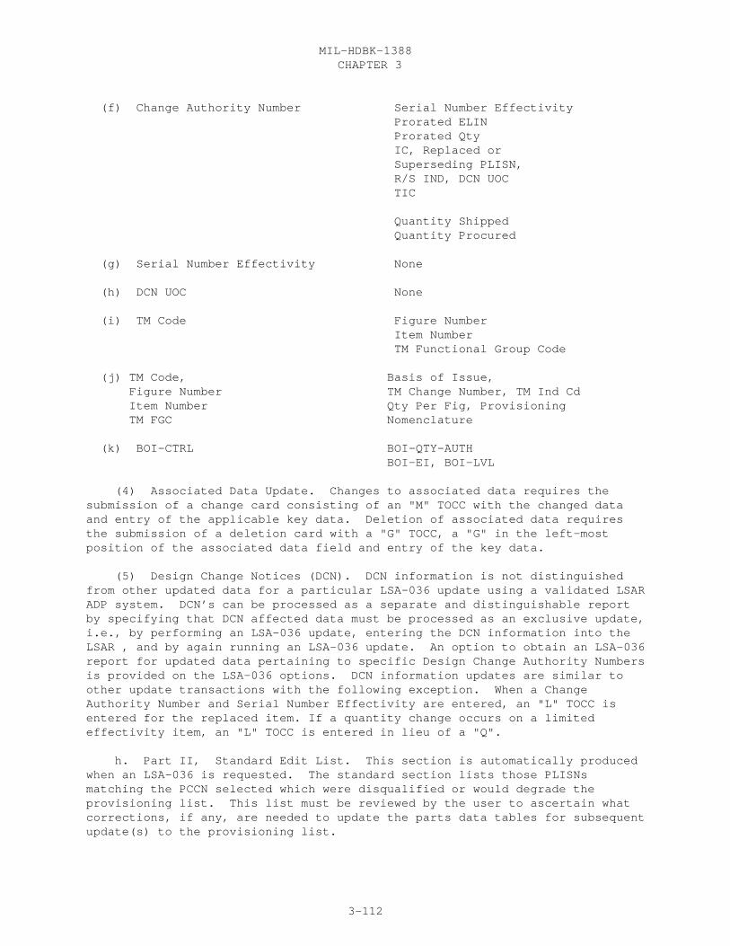
CHAPTER 3MIL-HDBK-1388
3-112
(f) Change Authority Number Serial Number Effectivity Prorated ELIN Prorated Qty IC, Replaced or Superseding PLISN, R/S IND, DCN UOC TIC
Quantity Shipped Quantity Procured
(g) Serial Number Effectivity None
(h) DCN UOC None
(i) TM Code Figure Number Item Number TM Functional Group Code
(j) TM Code, Basis of Issue, Figure Number TM Change Number, TM Ind Cd Item Number Qty Per Fig, Provisioning TM FGC Nomenclature
(k) BOI-CTRL BOI-QTY-AUTH BOI-EI, BOI-LVL
(4) Associated Data Update. Changes to associated data requires thesubmission of a change card consisting of an "M" TOCC with the changed dataand entry of the applicable key data. Deletion of associated data requiresthe submission of a deletion card with a "G" TOCC, a "G" in the left-mostposition of the associated data field and entry of the key data.
(5) Design Change Notices (DCN). DCN information is not distinguishedfrom other updated data for a particular LSA-036 update using a validated LSARADP system. DCN’s can be processed as a separate and distinguishable reportby specifying that DCN affected data must be processed as an exclusive update,i.e., by performing an LSA-036 update, entering the DCN information into theLSAR , and by again running an LSA-036 update. An option to obtain an LSA-036report for updated data pertaining to specific Design Change Authority Numbersis provided on the LSA-036 options. DCN information updates are similar toother update transactions with the following exception. When a ChangeAuthority Number and Serial Number Effectivity are entered, an "L" TOCC isentered for the replaced item. If a quantity change occurs on a limitedeffectivity item, an "L" TOCC is entered in lieu of a "Q".
h. Part II, Standard Edit List. This section is automatically producedwhen an LSA-036 is requested. The standard section lists those PLISNsmatching the PCCN selected which were disqualified or would degrade theprovisioning list. This list must be reviewed by the user to ascertain whatcorrections, if any, are needed to update the parts data tables for subsequentupdate(s) to the provisioning list.

CHAPTER 3MIL-HDBK-1388
3-113
i. Two optional part III listings are also available. Option 1 providesselectable provisioning data edits for Army customer use. Option 2 containsAir Force L card data formats to merge with the basic LSA-036 A-K cards.
j. PLISN range selection. The user may select START and STOP PLISNranges for inclusion on the LSA-036. Both the Start and Stop PLISN and allqualified PLISNs between are included on the report. All other PLISNs areexcluded.
k. Output Options. Output options are combinations of report, reportwith headers and/or output file of 80 card column PLISN records.
30.28.3 REPORT FORMAT. See Figure 3.25
30.28.4 REPORT SEQUENCE. The first record on the LSA-036 summary is thereport header. Following this, the report is sequenced in ascending PLISN. Within PLISN records are sequenced in ascending CFI. Within CFI records aresequenced in ascending TOCC in the following order: D or G before M, Q, or L.Within TOCC items are sorted in ascending CSN.
30.28.5 DATA SOURCE. The source of data appearing on the LSA-036 summary isdepicted below by data table and element codes.
Report header Table Code DED Element CodeCARD/BLOCK
PCCN XC 307 PCCNUMXC ALL/1 UOC HO/XC 501 UOCSEIXC PTD LISTS SELECTED PROVISIONING PARTS LIST HG 313 PPLPTDHG SHORT FORM PROVISIONING PARTS LIST HG 313 SFPPTDHG LONG LEAD TIME ITEMS LIST HG 313 LLIPTDHG REPAIRABLE ITEMS LIST HG 313 RILPTDHG INTERIM SUPPORT ITEMS LIST HG 313 ISLPTDHG TOOL AND TEST EQUIPMENT LIST HG 313 TTLPTDHG COMMON AND BULK ITEM LIST HG 313 CBLPTDHG POST CONFERENCE LIST HG 313 PCLPTDHG SYSTEM CONFIGURATION PPL HG 313 SCPPTDHG AS REQUIRED (A) HG 313 ARAPTDHG AS REQUIRED (B) HG 313 ARBPTDHG
PLISN XC 309 PLISNOXC ALL/2 HG 309 PLISNOHG TOCC XC 481 TOCCODXC ALL/3 HG 481 TOCCODHG IND CD HG 162 INDCODHG A/4 CAGE HA 046 CAGECDXH A/5 HB 046 ADCAGEHB REFERENCE NUMBER HA 337 REFNUMHA A/6 ADDITIONAL REFERENCE NUMBERS HB 006 ADDREFHB RNCC HA 338 REFNCCHA A/7 HB 338 ADRNCCHB RNVC HA 339 REFNVCHA A/8 HB 339 ADRNVCHB

CHAPTER 3MIL-HDBK-1388
3-114
DAC HA 086 DOCAVCHA A/9 PPSL HA 302 PPSLSTHA A/10 EC HG 100 ESSCODHG A/11 ITEM NAME HA 182 ITNAMEHA A/12 SL HA 377 SHLIFEHA A/13 SLAC HA 378 SLACTNHA A/14 CSN (GENERATED) CFI (GENERATED)
NSN AND RELATED DATA PRE HA 253 COGNSNHA B/15 HA 253 MATNSNHA FSC HA 253 FSCNSNHA NIIN HA 253 NIINSNHA SUFF HA 253 SMMNSNHA HA 253 ACTNSNHA UM HA 491 UNITMSHA B/16 UM PRICE HE 492 UMPRICHE B/17 [PROVISIONING UM PRICE] HE 314 PROUMPHE UI HA 488 UNITISHA B/18 UI PRICE HD 490 UIPRICHD [PROVISIONING UI PRICE] HD 314 PROUIPHD B/19 UI CONV HA 489 UICONVHA B/20
QUP HF 321 QTYUPKHF B/21 [DEGREE OF PROTECTION (C, B, A)] HF 074 DEGPROHF SMR HG 389 SMRCODHG B/22 DMIL HA 076 DEMILIHA B/23 PLT HA 299 PRDLDTHA B/24 HCI HG 151 HARDCIHG B/25 PSPC HA 291 PHYSECHA B/26 PMIC HA 293 PMICODHA B/27 ADP EC HA 027 ADPEQPHA B/28
NHA PLISN HH 258 NHAPLIHH C/29 NHA IND HH 259 NHAINDHH C/30 ORR HH 281 OVHREPHH C/31 QPA HG 316 QTYASYHG C/32 QPEI HG 317 QTYPEIHG C/33 MRR-I HG 211 MRRONEHG C/34 MRR-II HG 212 MRRTWOHG C/35 MRR MOD HG 213 MRRMODHG C/36 TOTAL REC QTY HG 453 TOTQTYHG C/37 SAME AS PLISN HG 364 SAPLISHG C/38 PRIOR PLISN HG 297 PIPLISHG C/39 MAOT HG 221 MAOTIMHG C/40 MAC HG 206 MAIACTHG C/41 NRTS HG 261 NORETSHG C/42
UOC HO/XC 501 UOCSEIXC D/43 HN/XD 375 SNUUOCXD REFERENCE DESIGNATION HJ 335 REFDESHJ D/44 RDOC (GENERATED) D/45 RDC HJ 336 RDCODEHJ D/46

CHAPTER 3MIL-HDBK-1388
3-115
SMCC HA 395 SPMACCHA D/47 PLCC HA 308 AAPLCCHA D/48 HA 308 BBPLCCHA HA 308 CCPLCCHA HA 308 DDPLCCHA HA 308 EEPLCCHA HA 308 FFPLCCHA HA 308 GGPLCCHA HA 308 HHPLCCHA HA 308 JJPLCCHA HA 308 KKPLCCHA HA 308 LLPLCCHA HA 308 MMPLCCHA SMIC HA 392 SMAINCHA D/49 AIC HG 017 ALLOWCHG D/50 AIC QTY HG 018 ALIQTYHG D/51 MRU HG 245 MINREUHG D/52 RMSSL HG 329 RMSSLIHG D/53 RISS BUY HG 328 RISSBUHG D/54 RTLL QTY HG 331 RTLLQTHG D/55 RSR HG 351 REPSURHG D/56
MAINT TASK DISTRIB O HG 214 OMTDOOHG E/57 F HG 214 FMTDFFHG H HG 214 HMTDHHHG SRA HG 214 LMTDLLHG D HG 214 DMTDDDHG CB HG 214 CBDMTDHG CA HG 214 CADMTDHG REPAIR CYCLE TIME--CON O HG 350 ORCTOOHG E/58 F HG 350 FRCTFFHG H HG 350 HRCTHHHG SRA HG 350 LRCTLLHG D HG 350 DRCTDDHG TAT HG 350 CONRCTHG REPLACEMENT TASK DIST O HG 355 ORTDOOHG E/59 F HG 355 FRTDFFHG H HG 355 HRTDHHHG SRA HG 355 LRTDLLHG D HG 355 DRTDDDHG DES REWORK PT ONE HG 081 DRPONEHG E/60 TWO HG 081 DRPTWOHG CTIC HA 058 CTICODHA E/61 AMC HA 003 ACQMETHA E/62 AMSC HA 004 AMSUFCHA E/63 IMC HA 181 ITMMGCHA E/64 RIP HG 348 REMIPIHG E/65
CHANGE AUTHORITY NUMBER HP 043 CANUMBHP F&G/66 IC HP 172 INTCHCHP F/67

CHAPTER 3MIL-HDBK-1388
3-116
SERIAL NUMBER EFFECTIVITY FROM HQ 374 FMSRNOHQ F/68 TO HQ 374 TOSRNOHQ TIC HP 452 TOTICHHP F/69 REP/SUP PLISN HP 353 RSPLISHP F/70 R/S IND HP 354 RSPINDHP F/71 QUANTITY SHIPPED HP 323 QTYSHPHP F/72 QUANTITY PROCURED HP 322 QTYPROHP F/73 DCN-UOC HR/HO/XC 501 UOCSEIXC F/74
PRORATED ELIN HP 305 PROELIHP G/75 PRORATED QUANTITY HP 306 PROQTYHP G/76
LCN HG 199 LSACONXB H/77 ALC HG 019 ALTLCNXB H/78 REMARKS HI 311 REMARKHI H/79
TM CODE HK 437 TMCODEXI J&K/80 FIG NO HK 144 FIGNUMHK J&K/81 ITEM NO HK 184 ITEMNOHK J&K/82 TM CHG HK 436 TMCHGNHK J/83 TM IND HK 439 TMINDCHK J/84 QTY FIG HK 318 QTYFIGHK J/85 WUC/TM FGC HG 516 WRKUCDHG J/86 HK 438 TMFGCDHK --BASIS OF ISSUE-- QTY-A HM 030 QTYBOIHM J/87 EI HM 030 RATIOBHM LV HM 030 LVLBOIHM CTR HM 030 BOICTRHM CC HA 066 CRITCDHA J/88 ITEM NAME CODE HA 183 INAMECHA J/89 LRU HG 194 LRUNITHG J/90
PROVISIONING NOMENCLATURE HL 310 PROVNOHL K/91
MATERIAL HA 218 MATERLHA M/92

CHAPTER 3MIL-HDBK-1388
3-117
LSA-036

CHAPTER 3MIL-HDBK-1388
3-118
30.29 LSA-037 SPARES AND SUPPORT EQUIPMENT IDENTIFICATION LIST REPORT SPECIFICATION
30.29.1 SELECTION. The LSA-037 report is selectable by mandatory EIAC, StartLCN, LCN TYPE, and UOC; and optional (ALC default is all ALCs), Stop LCN(default is all LCNs subordinate to, including, the start LCN), Report Parts(default is all parts), and ICC’S for each report part (default is allapplicable ICC’s).
The additional selection options by ICC and RPT PT consist of: a. RPT PT: 1. Part 1, enter a (y) if part 1 of the 037 report is required, otherwise, leave blank. 2. Part 2, enter a (y) if part 2 of the 037 report is required, otherwise, leave blank. 3. Part 3, enter a (y) if part 3 of the 037 report is required, otherwise, leave blank. 4. Part 4, enter a (y) if part 4 of the 037 report is required, otherwise, leave blank. b. Enter the ICC’s for which the report parts 1-4 are required. 1. Part 1, Investment Spare (ICC of X, AA) are allowed. 2. Part 2, Expense Spare (ICC of Y, Z, 9, AB, AE) are allowed. 3. Part 3, Support Equipment (ICC of G, H, 7, AD) are allowed. 4. Part 4, Tool and Test Equipment (ICC of D, M, N, P, R, V, 1-6, 8, AC) are allowed. See appendix E of MIL-STD-1388-2B for a listing and definitions of the various ICCs. These groupings will only have validity when definitions of the ICCs specified in appendix E of MIL-STD-1388-2B have been adhered to. c. If no ICC’s are selected for a selected report part (1-4) then all of the possible ICC’s for that report part are output.
30.29.2 PROCESSING. Items qualify for a particular section based on ICCs andthe report part selected. The Manufacturer’s Part Number (Reference Number) iswrapped at 16 positions. The MTBF’S are depicted by comparative analyzed (C),allocated (A), predicted (P), and measured (M) (Where a measured value has notbeen entered, the report will default to the predicted, then allocated, andfinally comparative analysis) (these come from RAM Indicator Code). The Unitof Measure Price that is pulled is identified by a "Y" in UM PriceProvisioning (PROUMPHE).
30.29.3 REPORT FORMAT. See Figure 3.26
30.29.4 REPORT SEQUENCE. Within each section the report is sequenced byascending manufacturer’s part number
30.29.5 DATA SOURCES. The source of the data appearing on the LSA-037summary is depicted below by data table and element codes.
Report Header Table Code DED Element Code EIAC XB 096 EIACODXA LCN NOMENCLATURE XB 201 LCNAMEXB START LCN XB 199 LSACONXB ALC XB 019 ALTLCNXB
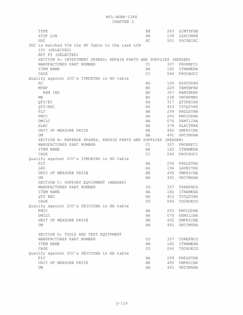
CHAPTER 3MIL-HDBK-1388
3-119
TYPE XB 203 LCNTYPXB STOP LCN XB 199 LSACONXB UOC XC 501 UOCSEIXCUOC is matched VIA the XF Table to the task LCN ICC (SELECTED) RPT PT (SELECTED) SECTION A: INVESTMENT SPARES; REPAIR PARTS AND SUPPLIES (HEADER) MANUFACTURES PART NUMBER CI 337 PROREFCI ITEM NAME HA 182 ITNAMEHA CAGE CI 046 PROCAGCIQualify against ICC’s ITMCATHG in HG table EC HG 100 ESSCODHG MTBF BD 229 TEMTBFBD RAM IND BD 347 RAMINDBD MB BD 238 TMTBFMBD QTY/EI HG 317 QTYPEIHG QTY/REC HG 453 TOTQTYHG PLT HA 299 PRDLDTHA PMIC HA 293 PMICODHA DMILC HA 076 DEMILIHA SLAC HA 378 SLACTNHA UNIT OF MEASURE PRICE HE 492 UMPRICHE UM HA 491 UNITMSHA SECTION B: EXPENSE SPARES, REPAIR PARTS AND SUPPLIES (HEADER) MANUFACTURES PART NUMBER CI 337 PROREFCI ITEM NAME HA 182 ITNAMEHA CAGE CI 046 PROCAGCIQualify against ICC’s ITMCATHG in HG table PLT HA 299 PRDLDTHA LRU HG 194 LRUNITHG UNIT OF MEASURE PRICE HE 492 UMPRICHE UM HA 491 UNITMSHA SECTION C: SUPPORT EQUIPMENT (HEADER) MANUFACTURES PART NUMBER CG 337 TSREFNCG ITEM NAME HA 182 ITNAMEHA QTY REC HG 453 TOTQTYHG CAGE CG 046 TSCAGECGQualify against ICC’s SEICCDEA in EA table PMIC HA 293 PMICODHA DMILC HA 076 DEMILIHA UNIT OF MEASURE PRICE HE 492 UMPRICHE UM HA 491 UNITMSHA
SECTION D: TOOLS AND TEST EQUIPMENT MANUFACTURES PART NUMBER CG 337 TSREFNCG ITEM NAME HA 182 ITNAMEHA CAGE CG 046 TSCAGECGQualify against ICC’s SEICCDEA in EA table PLT HA 299 PRDLDTHA UNIT OF MEASURE PRICE HE 492 UMPRICHE UM HA 491 UNITMSHA

CHAPTER 3MIL-HDBK-1388
3-120
LSA-037
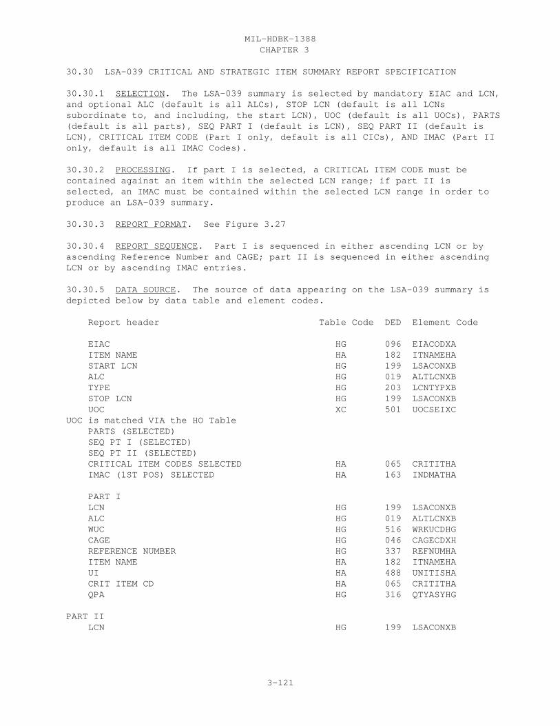
CHAPTER 3MIL-HDBK-1388
3-121
30.30 LSA-039 CRITICAL AND STRATEGIC ITEM SUMMARY REPORT SPECIFICATION
30.30.1 SELECTION. The LSA-039 summary is selected by mandatory EIAC and LCN,and optional ALC (default is all ALCs), STOP LCN (default is all LCNssubordinate to, and including, the start LCN), UOC (default is all UOCs), PARTS(default is all parts), SEQ PART I (default is LCN), SEQ PART II (default isLCN), CRITICAL ITEM CODE (Part I only, default is all CICs), AND IMAC (Part IIonly, default is all IMAC Codes).
30.30.2 PROCESSING. If part I is selected, a CRITICAL ITEM CODE must becontained against an item within the selected LCN range; if part II isselected, an IMAC must be contained within the selected LCN range in order toproduce an LSA-039 summary.
30.30.3 REPORT FORMAT. See Figure 3.27
30.30.4 REPORT SEQUENCE. Part I is sequenced in either ascending LCN or byascending Reference Number and CAGE; part II is sequenced in either ascendingLCN or by ascending IMAC entries.
30.30.5 DATA SOURCE. The source of data appearing on the LSA-039 summary isdepicted below by data table and element codes.
Report header Table Code DED Element Code
EIAC HG 096 EIACODXA ITEM NAME HA 182 ITNAMEHA START LCN HG 199 LSACONXB ALC HG 019 ALTLCNXB TYPE HG 203 LCNTYPXB STOP LCN HG 199 LSACONXB UOC XC 501 UOCSEIXCUOC is matched VIA the HO Table PARTS (SELECTED) SEQ PT I (SELECTED) SEQ PT II (SELECTED) CRITICAL ITEM CODES SELECTED HA 065 CRITITHA IMAC (1ST POS) SELECTED HA 163 INDMATHA
PART I LCN HG 199 LSACONXB ALC HG 019 ALTLCNXB WUC HG 516 WRKUCDHG CAGE HG 046 CAGECDXH REFERENCE NUMBER HG 337 REFNUMHA ITEM NAME HA 182 ITNAMEHA UI HA 488 UNITISHA CRIT ITEM CD HA 065 CRITITHA QPA HG 316 QTYASYHG
PART II LCN HG 199 LSACONXB

CHAPTER 3MIL-HDBK-1388
3-122
ALC HG 019 ALTLCNXB WUC HG 516 WRKUCDHG CAGE HG 046 CAGECDXH REFERENCE NUMBER HG 337 REFNUMHA PLISN HG 309 PLISNOHG XC 309 PLISNOXC NHA-PLISN HH 258 NHAPLIHH NHA-IND HH 259 NHAINDHH NHA-CAGE HG 046 CAGECDXH NHA-REFERENCE-NUMBER HG 337 REFNUMHA ITEM NAME HA 182 ITNAMEHA UI HA 488 UNITISHA MAT-WT HA 220 MTLWGTHA MAT-LEAD HA 219 MTLEADHA QPA HG 316 QTYASYHG IMAC HA 163 INDMATHA

CHAPTER 3MIL-HDBK-1388
3-123
LSA-039

CHAPTER 3MIL-HDBK-1388
3-124
30.31 LSA-040 AUTHORIZATION LIST ITEMS SUMMARY REPORT SPECIFICATION
FIRST TIER SELECTION: The First selection is only one of the following:
Option 1: COEI, BII, AAL, and ESML Lists Option 2: Stockage List Type Three
OPTION 1, COEI, BII, AAL, AND ESML LISTS.
30.31.1 SELECTION. The LSA-040 summary is selected by mandatory LCN, andoptional ALC, STOP LCN, UOC,
30.31.2 PROCESSING. Option 1 is divided into four sections: components ofend item, basic issue items list, additional authorization list, and expendabledurable supplies and materials list. The items are identified by code A inposition 1 and the appropriate list code in position 2 of the Allowance ItemCode (AICODEHG).
a. Section I, Components of End Item (COEI) List. This section providesa listing of those items which are part of the end item, but are removed andseparately packaged for transportation or shipment. The items are listed inalphabetical sequence of Item Name (ITNAMEHA) and are identified by a "C" inthe second position of the AIC. ILLUS NO. is computer generated based on theitem sequence. if Section II is also required, then the computer generatedILLUS NO. is not reset to 1 but continues with the next sequence number.
b. Section II, Basic Issue Items (BII) List. This section provides alisting of those minimum essential items required to place an equipment inoperation, to operate it, and to perform emergency repairs. The items arelisted in alphabetic sequence of Item Name (ITNAMEHA) and are identified by"A" in the second position of the AIC.
c. Section III, Additional Authorization List (AAL). This section pro-vides a listing of those items which are not issued with an end item and arenot listed/identified on the end item engineering drawings as part of the enditem configuration. The items are listed in alphabetic sequence by item name(ITNAMEHA) within each subsection. AAL-MTOE Authorized are identified by AICof "E" and AAL-Other Authorized are identified by AIC, second position of "F".
Section IV, Expendable/Durable Supplies and Materials List (ESML) provides alisting of those expendable/durable supplies and materials required to operateand maintain the equipment. The items are listed in alphabetic sequence byitem name (ITNAMEHA) and are identified by AIC, second position of "D". ITEMNO is computer generated. Level is determined by the SMR (3d position).
30.31.3 REPORT FORMAT. See Figure 3.28
30.31.4 REPORT SEQUENCE. Alphabetical sequence of Item Name. Secondary Sorton NSN.
30.31.5. DATA SOURCE. See attached listings.

CHAPTER 3MIL-HDBK-1388
3-125
OPTION 2. STOCKAGE LIST TYPE THREE
30.31.1 SELECTION. The LSA-040 option 2 is selected by mandatory LCN, andoptional ALC, STOP LCN, UOC, and LIST section.
30.31.2 PROCESSING. In order to produce Option 2 of the LSA-040 summary, atleast one entry of an Allowance Item Code of "E" in the first position, and theapplicable code for the selected section(s) must be contained within theselected LCN range. "Ref Desig Fig-Key" is only printed if Ref Des Code = F. If item qualifies and no RDC = F, leave Ref Desig Fig-Key blank. Sort blanksfirst in each section with 2nd sort on NSN.
a. Section I, Supply System Responsibility consists of AIC items coded"A" and "D"in the second position. The items coded "D" will show the AICQuantity (AICQTYHG) preceding the Item Name in the description column. "ED"coded items will be indented 2 spaces and AIC quantities printed preceding itemname and provisioning nomenclature, instead of printing QTYPEIHG value in "QTYUSED IN UNIT" column, as is the case for "EA" coded items and all other itemsin ither sections. Section II, Using unit Responsibility, is determined by AICvalues of "C" in the second position. Section III, Collateral Equipment isdetermined by AIC value of "E" in the second position.
b. ITEM NO. is a computer generated sequence number assigned to each itembeginning with 0001. If multiple sections are present, the Item number is NOTreset to 1.
30.31.3 REPORT FORMAT. See Figure 3.28
30.31.4 REPORT SEQUENCE. Items are sequenced in ascending ReferenceDesignation and LCN within each section.
30.31.5 DATA SOURCE. The source of data appearing on the LSA-040 summary isdepicted below by data table and element codes.
Report header Table Code DED Element CodeOPTION 1, COEI,BII, AAL, ESML EIAC HG 096 EIACODXA ITEM NAME HA 182 ITNAMEHA START LCN HG 199 LSACONXB ALC HG 019 ALTLCNXB TYPE HG 203 LCNTYPXB STOP LCN HG 199 LSACONXB UOC HO/XC 501 UOCSEIXC AUTH LISTS SELECTED HG 017 ALLOWCHG
ILLUS NO (GENERATED) NSN HA 253 FSCNSNHA HA 253 NIINSNHA DESCRIPTION, CAGE AND REFERENCE NUMBER [LCN] HG 199 LSACONXB [ALC] HG 019 ALTLCNXB

CHAPTER 3MIL-HDBK-1388
3-126
[AIC] HG 017 ALLOWCHG (ITEM NAME) HA 182 ITNAMEHA (PROVISIONING NOMENCLATURE) HL 310 PROVNOHL CAGE HA 046 CAGECDXH REFERENCE NUMBER HA 337 REFNUMHA UOC HO/XC 501 UOCSEIXC UM HA 491 UNITMSHA QTY REQ HG 018 ALIQTYHG PART III QTY AUTH HG 018 ALIQTYHG USABLE ON CODE HO/XC 501 UOCSEIXC PART IV LEVEL HG 389 SMRCODHG
OPTION 2 STOCKAGE LIST TYPE THREE Report header Table Code DED Element Code EIAC HG 096 EIACODXA ITEM NAME HA 182 ITNAMEHA START LCN HG 199 LSACONXB ALC HG 019 ALTLCNXB TYPE HG 203 LCNTYPXB STOP LCN HG 199 LSACONXB UOC HO/XC 501 UOCSEIXC LISTS OF COMPONENTS REQUIRED HG 017 ALLOWCHG
ITEM NO. (GENERATED) NATIONAL STOCK NUMBER HA 253 FSCNSNHA HA 253 NIINSNHA REF DESIG FIG-KEY HJ 335 REFDESHJ [RDC] HJ 336 RDCODEHJ MODEL HO/XC 501 UOCSEIXC ITEM IDENTIFICATION
(ALLOWANCE ITEM QUANTITY)("ED AIC ONLY) HG 018 ALIQTYHG (ITEM NAME) HA 182 ITNAMEHA (PROVISIONING NOMENCLATURE) HL 310 PROVNOHL UM HA 491 UNITMSHA QTY USED IN UNIT HG 317 QTYPEIHG XC 317 QTYPEIXC LCN HG 199 LSACONXB ALC HG 019 ALTLCNXB AIC HG 017 ALLOWCHG CAGE HG 046 CAGECDXH ADDRESS XH 047 CANAMEXH XH 047 CASTREXH XH 047 CACITYXH XH 047 CASTATXH XH 047 CANATNXH XH 047 CAPOZOXH

CHAPTER 3MIL-HDBK-1388
3-127
LSA-040

CHAPTER 3MIL-HDBK-1388
3-128

CHAPTER 3MIL-HDBK-1388
3-129
30.32 LSA-046 NUCLEAR HARDNESS CRITICAL ITEMS SUMMARY REPORT SPECIFICATION
30.32.1 SELECTION. The LSA-046 summary is selected by mandatory EIAC and LCN,and optional ALC (default is all ALCs), STOP LCN (default is all LCNssubordinate to, and including, the start LCN), UOC (default is all UOCs) andSEQ OPT (default is reference number CAGE).
30.32.2 PROCESSING. Items are primarily qualified by HCI entries of "Y". Inorder to produce an LSA-046 summary at least one Hardness Critical Item value(HARDCIHG) of "Y" must be contained within the selected Start and Stop LCNrange. If the report is sequenced by Reference Number and CAGE, then theReference Number, CAGE, Item Name, and IMC are suppressed on the second andsubsequent application (PCCN/PLISN) of the same part number.
30.32.3 REPORT FORMAT. See Figure 3.29
30.32.4 REPORT SEQUENCE. The report is sequenced in either ascendingReference Number and CAGE or PCCN/PLISN.
30.32.5 DATA SOURCE. The source of data appearing on the LSA-046 summary isdepicted below by data table and element codes.
Report header Table Code DED Element Code EIAC HG 096 EIACODXA ITEM NAME HA 182 ITNAMEHA START LCN HG 199 LSACONXB ALC HG 019 ALTLCNXB TYPE HG 203 LCNTYPXB STOP LCN HG 199 LSACONXB UOC XC 501 UOCSEIXCUOC is matched VIA the HO Table SEQ OPT (SELECTED) [HARDNESS CRITICAL ITEM] HG 151 HARDCIHG
REFERENCE NUMBER HG 337 REFNUMHA CAGE HG 046 CAGECDXH ITEM NAME HA 182 ITNAMEHA IMC HA 181 ITMMGCHA SMR HG 389 SMRCODHG PCCN XC 307 PCCNUMXC PLISN HG 309 PLISNOHG IND HG 162 INDCODHG QTY/ASSY HG 316 QTYASYHG QTY/EI HG 317 QTYPEIHG
CHAPTER 3MIL-HDBK-1388
3-130
LSA-046
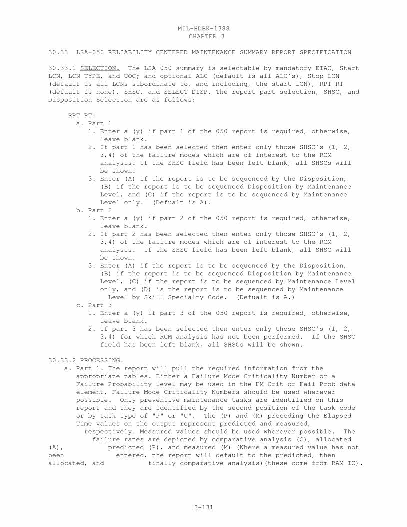
CHAPTER 3MIL-HDBK-1388
3-131
30.33 LSA-050 RELIABILITY CENTERED MAINTENANCE SUMMARY REPORT SPECIFICATION
30.33.1 SELECTION. The LSA-050 summary is selectable by mandatory EIAC, StartLCN, LCN TYPE, and UOC; and optional ALC (default is all ALC’s), Stop LCN(default is all LCNs subordinate to, and including, the start LCN), RPT RT(default is none), SHSC, and SELECT DISP. The report part selection, SHSC, andDisposition Selection are as follows:
RPT PT: a. Part 1 1. Enter a (y) if part 1 of the 050 report is required, otherwise, leave blank. 2. If part 1 has been selected then enter only those SHSC’s (1, 2, 3,4) of the failure modes which are of interest to the RCM analysis. If the SHSC field has been left blank, all SHSCs will be shown. 3. Enter (A) if the report is to be sequenced by the Disposition, (B) if the report is to be sequenced Disposition by Maintenance Level, and (C) if the report is to be sequenced by Maintenance Level only. (Defualt is A). b. Part 2 1. Enter a (y) if part 2 of the 050 report is required, otherwise, leave blank. 2. If part 2 has been selected then enter only those SHSC’s (1, 2, 3,4) of the failure modes which are of interest to the RCM analysis. If the SHSC field has been left blank, all SHSC will be shown. 3. Enter (A) if the report is to be sequenced by the Disposition, (B) if the report is to be sequenced Disposition by Maintenance Level, (C) if the report is to be sequenced by Maintenance Level only, and (D) is the report is to be sequenced by Maintenance Level by Skill Specialty Code. (Defualt is A.) c. Part 3 1. Enter a (y) if part 3 of the 050 report is required, otherwise, leave blank. 2. If part 3 has been selected then enter only those SHSC’s (1, 2, 3,4) for which RCM analysis has not been performed. If the SHSC field has been left blank, all SHSCs will be shown.
30.33.2 PROCESSING. a. Part 1. The report will pull the required information from the appropriate tables. Either a Failure Mode Criticality Number or a Failure Probability level may be used in the FM Crit or Fail Prob data element, Failure Mode Criticality Numbers should be used wherever possible. Only preventive maintenance tasks are identified on this report and they are identified by the second position of the task code or by task type of "P" or "U". The (P) and (M) preceding the Elapsed Time values on the output represent predicted and measured, respectively. Measured values should be used wherever possible. The failure rates are depicted by comparative analysis (C), allocated(A), predicted (P), and measured (M) (Where a measured value has notbeen entered, the report will default to the predicted, thenallocated, and finally comparative analysis)(these come from RAM IC).
CHAPTER 3MIL-HDBK-1388
3-132
b. Part 2, The report will pull the required information from the appropriate tables, except for:
The LCN (AA) and inherent availability (AA) are from the system/end item these are based on the end item whether or not it is with the LCN selection.
If the task type (B) is "U" (Usage based) then calculate the task frequency using this calculation.
Calculated Task Frequencies. The task frequency can be calculated by:
AOR X Conv Fact (The preventive TF will be calculated TF = ---------------------- for only that item that the task is Maintenance Interval being done against).
The MB from the AOR and the Maintenance interval must match, otherwise it can not be calculated.
The AOR for the calculation is based on the LCN AOR from the CA table via the link between the B (task requirement LCN) and the LCN from CA tables through the Task Code.
If the task type is "P" (calendar time) for preventive maintenance task first check the 2nd position of the task code if it is Q, C, P, M, N, or L then convert it to a task frequency. If the 2nd position of the task code is "B" (schedule) then the task frequency is the maintenance interval (MB) (converted) divided by the maintenance interval. (example) the maintenance interval is 2 and MB is T (months) (converted = 12) therefore the TF is 12/2 or 6. This applies only to the MB codes of D, G, H, T, and Y. All other MB codes are usage based, Task Type = "U", and do not apply to the calendar time conversion.
The Total number of Man-Hours will be summed up for the Maintenance Level for each of the SSC’s used in that maintenance level and output at the bottom of each maintenance level. MH/SSC and Maintenance Level = Sum of Mean Man-minutes per SSC and O/M level divided by 60 to convert to hours.
Either a Failure Mode Criticality Number or a Failure Probability level may be used in the FM Crit or Fail Prob data element, Failure Mode Criticality Numbers should be used wherever possible. The (P) and (M) preceding the Elapsed Time and Man Hour values on the output represent predicted and measured, respectively. Measured values should be used wherever possible. The failure rates are denoted by comparative analysis (C), allocated (A), predicted (P), and measured (M) (Where a measured value has not been entered, the report will default to the predicted, then allocated, and finally comparative analysis) (these come from RAM Indicator Code).
c. Part 3 of the report will pull the required information from the appropriate tables. Either a Failure Mode Criticality Number or a Failure Probability level may be used in the FM Crit or Fail Prob data element, Failure Mode Criticality Numbers should be used wherever

CHAPTER 3MIL-HDBK-1388
3-133
possible. d. Each part of the 050 report should start at the top of a new page.
30.33.3 REPORT FORMAT. See Figure 3.30
30.33.4 REPORT SEQUENCING. a. Part 1. 1. Select Disp of (A), the report is sequenced by ascending Disposition values then LCN then Task Code. 2. Select Disp of (B), the report is sequenced ascending Disposition by Maintenance Level, the first being Crew the last being Depot, then LCN then Task Code. 3. Select Disp of (C), the report is sequenced by Maintenance Level, the first being crew the last depot, then LCN then Task Code. b. Part 2. 1. Select Disp of (A), the report is sequenced by ascending Disposition values then LCN then Task Code. 2. Select Disp of (B), the report is sequenced ascending Disposition by Maintenance Level, the first being Crew the last being Depot, then LCN then Task Code. 3. Select Disp of (C), the report is sequenced by Maintenance Level, the first being crew the last depot, then LCN then Task Code. 4. Select Disp of (D), the report is sequenced by ascending Skill Specialty Code then Maintenance Level then LCN then Task Code. c. Part 3. Shall be sorted by ascending LCN, FMI, MPC, and SHSC.
30.33.5 DATA SOURCES. The source of the data appearing on the LSA-050 summaryis depicted below by data table and element codes. Report Header Table Codes Ded Element Code EIAC XB 096 EIACODXA LCN NOMENCLATURE XB 201 LCNAMEXB START LCN XB 199 LSACONXB ALC XB 019 ALTLCNXB TYPE XB 203 LCNTYPXB STOP LCN XB 199 LSACONXB UOC XC 501 UOCSEIXCUOC is matched VIA the XF Table SHSC (SELECTED) RPT PT (SELECTED) SELECT DISP (SELECTED)
LOGIC UTILIZED AA 345 RCMLOGAA LCN BA 199 LSACONXB ALC BA 019 ALTLCNXB LCN NOMENCLATURE XB 201 LCNAMEXB SHSC BI 362 FMSHSCBI FMI BI 134 FAMOINBF MPC BI 246 MISSPCBL LOGIC RESULTS (HEADER) 01 BF 344 RCMRO1BF 02 BF 344 RCMRO2BF 03 BF 344 RCMRO3BF 04 BF 344 RCMRO4BF 05 BF 344 RCMRO5BF
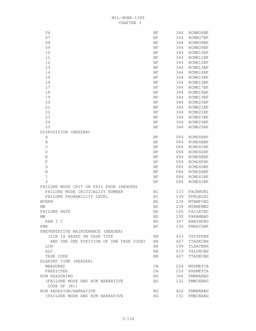
CHAPTER 3MIL-HDBK-1388
3-134
06 BF 344 RCMRO6BF 07 BF 344 RCMRO7BF 08 BF 344 RCMRO8BF 09 BF 344 RCMRO9BF 10 BF 344 RCMR10BF 11 BF 344 RCMR11BF 12 BF 344 RCMR12BF 13 BF 344 RCMR13BF 14 BF 344 RCMR14BF 15 BF 344 RCMR15BF 16 BF 344 RCMR16BF 17 BF 344 RCMR17BF 18 BF 344 RCMR18BF 19 BF 344 RCMR19BF 20 BF 344 RCMR20BF 21 BF 344 RCMR21BF 22 BF 344 RCMR22BF 23 BF 344 RCMR23BF 24 BF 344 RCMR24BF 25 BF 344 RCMR25BF DISPOSITION (HEADER) A BF 084 RCMDSABF B BF 084 RCMDSBBF C BF 084 RCMDSCBF D BF 084 RCMDSDBF E BF 084 RCMDSEBF F BF 084 RCMDSFBF G BF 084 RCMDSGBF H BF 084 RCMDSHBF I BF 084 RCMDSIBF J BF 084 RCMDSJBF FAILURE MODE CRIT OR FAIL PROB (HEADER) FAILURE MODE CRITICALITY NUMBER BI 133 FACRNUBI FAILURE PROBABILITY LEVEL BI 139 FPROBLBI MTBPM BD 234 MTBMPVBD MB BD 238 MTBMPMBD FAILURE RATE BD 140 FAILRTBD MB BD 238 FARAMBBD RAM I C BD 347 RAMINDBD FMR BF 136 FMRATOBF PREVENTATIVE MAINTENANCE (HEADER) (LCN IS BASED ON TASK TYPE BH 433 TATYPEBH AND THE 2ND POSITION OF THE TASK CODE) BH 427 TTASKCBH LCN BH 199 TLSACNBH ALC BH 019 TALCNCBH TASK CODE BH 427 TTASKCBH ELAPSED TIME (HEADER) MEASURED CA 224 MSDMETCA PREDICTED CA 224 PRDMETCA RCM REASONING BG 346 FMNNARBG (FAILURE MODE AND RCM NARRATIVE BG 131 FMNCNABG CODE OF (K)) RCM REDESIGN/NARRATIVE BG 426 FMNNARBG (FAILURE MODE AND RCM NARRATIVE BG 131 FMNCNABG

CHAPTER 3MIL-HDBK-1388
3-135
CODE OF (L)) RCM AGE EXPLORATION BG 343 FMNNARBG (FAILURE MODE AND RCM NARRATIVE BG 131 FMNCNABG CODE OF (J))
PART II
LCN END ITEM AA 199 LSACONXB INHERENT AVAILABILITY END ITEM AA 164 INHAVAAA MAINTENANCE LEVEL BH 427 TTASKCBH (3RD POSITION OF TASK CODE) LCN BH 199 LSACONXB ALC BH 019 ALTLCNXB LCN NOMENCLATURE XB 201 LCNAMEXB AOR AG 023 ANOPREAG MB AG 238 MEASBSAG (AOR IS BASED ON LCN AOR LINK FROM CA TABLE VIA TASK CODE, PEACETIME) IA BD 164 INHAVABD DISPOSITION (HEADER) A BF 084 RCMDSABF B BF 084 RCMDSBBF C BF 084 RCMDSCBF D BF 084 RCMDSDBF E BF 084 RCMDSEBF F BF 084 RCMDSFBF G BF 084 RCMDSGBF H BF 084 RCMDSHBF I BF 084 RCMDSIBF J BF 084 RCMDSJBF TASK LCN BH 199 TLSACNBH ALC BH 019 TALCNCBH TASK CODE BH 427 TTASKCBH TABLE CA TASK FREQ CA 430 TSKFRQCA MB CA 238 AORMSBCA
CALCULATED TASK FREQ BH 427 TTASKCBH (IF TASK TYPE IS P THEN CONVERT OR USING THE STEPS REFERENCED IN PART 2 BH 208 MAININBH PARAGRAPH) BH 238 MAINMBBH
CALCULATED TASK FREQ (CALCULATED) (IF TASK TYPE IS CODED "U" THEN CALCULATE BH 433 TATYPEBH USING FORMULA. AOR AND MAINTENANCE INTERVAL MUST MATCH OTHER WISE LEAVE BLANK) MB (TAKEN FROM THE CALCULATIONS) AOR AG 023 ANOPREAG (AOR IS BASED ON LCN AOR LINK FROM CA TABLE VIA TASK CODE) MB AG 238 MEASBSAG CONV FACT BA 059 CONVFABA MAINTENANCE INTERVAL BH 208 MAININBH MB BH 238 MAINMBBH MAN HOURS (HEADER) MEASURED CA 225 MSDMMHCA
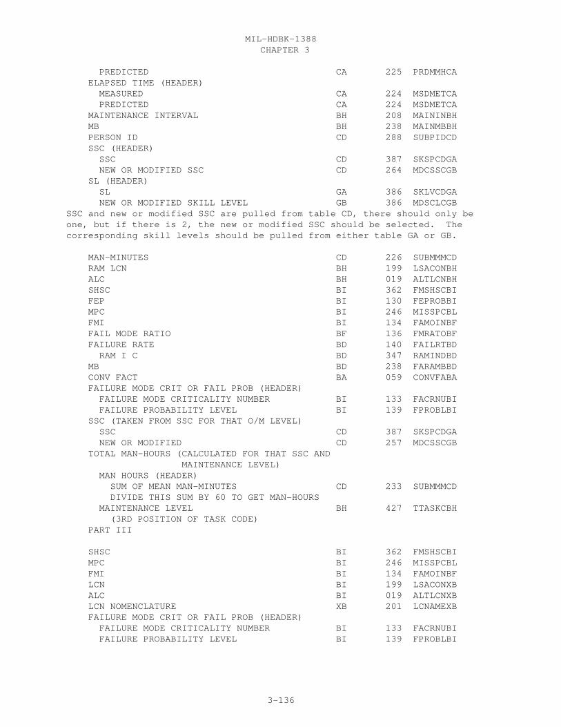
CHAPTER 3MIL-HDBK-1388
3-136
PREDICTED CA 225 PRDMMHCA ELAPSED TIME (HEADER) MEASURED CA 224 MSDMETCA PREDICTED CA 224 MSDMETCA MAINTENANCE INTERVAL BH 208 MAININBH MB BH 238 MAINMBBH PERSON ID CD 288 SUBPIDCD SSC (HEADER) SSC CD 387 SKSPCDGA NEW OR MODIFIED SSC CD 264 MDCSSCGB SL (HEADER) SL GA 386 SKLVCDGA NEW OR MODIFIED SKILL LEVEL GB 386 MDSCLCGBSSC and new or modified SSC are pulled from table CD, there should only beone, but if there is 2, the new or modified SSC should be selected. Thecorresponding skill levels should be pulled from either table GA or GB.
MAN-MINUTES CD 226 SUBMMMCD RAM LCN BH 199 LSACONBH ALC BH 019 ALTLCNBH SHSC BI 362 FMSHSCBI FEP BI 130 FEPROBBI MPC BI 246 MISSPCBL FMI BI 134 FAMOINBF FAIL MODE RATIO BF 136 FMRATOBF FAILURE RATE BD 140 FAILRTBD RAM I C BD 347 RAMINDBD MB BD 238 FARAMBBD CONV FACT BA 059 CONVFABA FAILURE MODE CRIT OR FAIL PROB (HEADER) FAILURE MODE CRITICALITY NUMBER BI 133 FACRNUBI FAILURE PROBABILITY LEVEL BI 139 FPROBLBI SSC (TAKEN FROM SSC FOR THAT O/M LEVEL) SSC CD 387 SKSPCDGA NEW OR MODIFIED CD 257 MDCSSCGB TOTAL MAN-HOURS (CALCULATED FOR THAT SSC AND MAINTENANCE LEVEL) MAN HOURS (HEADER) SUM OF MEAN MAN-MINUTES CD 233 SUBMMMCD DIVIDE THIS SUM BY 60 TO GET MAN-HOURS MAINTENANCE LEVEL BH 427 TTASKCBH (3RD POSITION OF TASK CODE) PART III
SHSC BI 362 FMSHSCBI MPC BI 246 MISSPCBL FMI BI 134 FAMOINBF LCN BI 199 LSACONXB ALC BI 019 ALTLCNXB LCN NOMENCLATURE XB 201 LCNAMEXB FAILURE MODE CRIT OR FAIL PROB (HEADER) FAILURE MODE CRITICALITY NUMBER BI 133 FACRNUBI FAILURE PROBABILITY LEVEL BI 139 FPROBLBI

CHAPTER 3MIL-HDBK-1388
3-137
lsa-050

CHAPTER 3MIL-HDBK-1388
3-138

CHAPTER 3MIL-HDBK-1388
3-139
30.34 LSA-056 FAILURE MODE, EFFECTS, AND CRITICALITY ANALYSIS (FMECA) REPORTREPORT SPECIFICATION
30.34.1 SELECTION. The LSA-056 summary is selectable by mandatory EIAC, StartLCN, LCN TYPE, UOC and SERV DES; and optional ALC (default is all ALCs), StopLCN (default is all LCNs subordinate to, and including, the start LCN), and RPTRT.The report part selections consist of:
RPT PT: a. Part 1 1. Enter a (y) if part 1 of the 056 report is required, otherwise, leave blank. 2. If part 1 has been selected then enter only those SHSC’s (1, 2, 3,4) of the failure modes which are of interest. If the SHSC field has been left blank, data involving only SHSC’s of 1 and 2 will be reported. b. Part 2 1. Enter a (y) if part 2 of the 056 report is required, otherwise, leave blank. 2. If part 1 has been selected then enter only those SHSC’s (1, 2, 3,4) of the failure modes which are of interest. If the SHSC field has been left blank, data involving only SHSC’s of 1 and 2 will be reported. 3. Enter the lowest values of a failure mode criticality number to be included in the report. If an entry is made in b.4, Failure Probability Level then leave this field blank. 4. Enter the lowest value of a Failure Probability Level to be include in the report. An entry must be made in either b.3 or in in this field. If an entry is made in both blocks; failure probability level is disregarded. c. Part 3 1. Enter a (y) if part 3 of the 056 report is required, otherwise, leave blank. 2. If part 1 has been selected then enter only those SHSC’s (1, 2, 3,4) of the failure modes which are of interest. If the SHSC field has been left blank, data involving only SHSC’s of 1 and 2 will be reported.
30.34.2 PROCESSING. a. Part 1. The report will pull the information from the appropriate tables, except for: j Calculated Item Criticality Number, Cr = � (Cm)n n=1,2,3.....j n=1 where Cr = Criticality Number for the item Cm = Failure Mode Criticality Number n = The failure modes in the items that fail under a particular severity classification/mission phase combination j = Last failure mode in the item under the severity classification/mission phase combination

CHAPTER 3MIL-HDBK-1388
3-140
Calculated Failure Mode Criticality Number Cm = (B*a*FR*T)(1,000,000.)
B = Failure Effect Probability a = Failure Mode Ratio FR = Failure Rate t = Operating Time
NOTE: FM Criticality Number is computed for each LCN/ALC and Failure Mode combination.
This report will print a part 1 for each LCN that Falls within the LCN select range. The failure rates are depicted by comparative analysis (C), allocated (A), predicted (P), and measured (M) (Where a measured value has not been entered, the report will default to the predicted, then allocated, and finally comparative analysis) (these come from RAM Indicator Code). If Type is (F) the Reference Number and CAGE may not appear on report. Use the second position of the task code for identifying corrective maintenance tasks.
b. Part 2 of the report will pull the required information from the appropriate tables. Reference Number is wrapped at 16 positions.
c. Part 3 of the report will pull the required information from the appropriate tables, except for:
Calculated Failure Mode Criticality Number Cm = (B*a*FR*T)(1,000,000.)
B = Failure Effect Probability a = Failure Mode Ratio FR = Failure Rate t = Operating Time
NOTE: FM Criticality Number is computed for each LCN/ALC and Failure Mode combination.
The Failure mode ratio(s) for an LCN should be added up (TOTAL) and placed on the report. An edit check should be made against this total to make sure it never exceeds 1.00. If the total of the Failure Mode are greater than 1.00 then an (***) should appear.
j Total = � FMR n=1
FMR = Failure Mode Ratio n = The failure modes indicator that falls under a particular LCN, ALC, and FMI combination j = Last failure mode indicator in the LCN and ALC combination
The failure rates are depicted by comparative analysis (C), allocated (A), predicted (P), and measured (M) (Where a measured value has not

CHAPTER 3MIL-HDBK-1388
3-141
been entered, the report will default to the predicted, then allocated, and finally comparative analysis)
d. Each part of the 056 report should start at the top of a new page.
30.34.3 REPORT FORMAT. See Figure 3.31
30.34.4 REPORT SEQUENCING. a. Part 1, The report is sequenced by ascending values of LCN then FMI then MPC then SHSC. Part 1 will be produced once for each LCN ALC combination which falls within the select range.
b. Part 2, The report is sequenced by ascending values of FPL or descending values of FM Crit for a LCN/ALC and FMI.
c. Part 3, The report is sequenced by ascending values of LCN, ALC, FMI, and MPC.
30.34.5 DATA SOURCE. The source of the data appearing on the LSA-056 summaryis depicted below by data table and element codes.
Report Header Table Codes Ded Element Code EIAC XB 096 EIACODXA LCN NOMENCLATURE XB 201 LCNAMEXB START LCN XB 199 LSACONXB ALC XB 019 ALTLCNXB TYPE XB 203 LCNTYPXB STOP LCN XB 199 LSACONXB UOC XC 501 UOCSEIXCUOC is matched VIA the XF Table SERVICE DESIGNATOR (SELECTED)Use the fourth position of the task code todistinguish the SER DES BH 427 TTASKCBH RPT PR (SELECTED) SHSC (SELECTED)
PART I --- FMECA WORKSHEET SUMMARY ---
LCN BA 199 LSACONXB ALC BA 019 ALTLCNXB LCN-TYPE BA 203 LCNTYPXB LCN NOMENCLATURE XB 201 LCNAMEXB FAILURE RATE BD 140 FAILRTBD FR MB BD 238 FARAMBBD RAM I C BD 347 RAMINDBD FAIL RATE SOURCE BA 141 FRDATABA
DRAWING NUMBER (HEADER) REFERENCE NUMBER HA 337 REFNUMHA ADDITIONAL REFERENCE NUMBER HB 337 REFNUMHBTo retrieve a drawing number you will need to check first in the HA table tosee if the reference number documented in that area is a drawing number. Tomake this check look at the Reference number category Code and see if the code

CHAPTER 3MIL-HDBK-1388
3-142
of "D" has been entered. If a "D" has not been entered check in the HB tableunder additional reference number and go through the same check of the ARNCC.
REFERENCE NUMBER HG 337 REFNUMHA CAGE HG 046 CAGECDXH ITEM FUNCTION BB 180 RAMNARBB (RAM CHARACTERISTICS NARRATIVE BB 341 RAMCNABB CODE OF (A)) CRIT MPC BK 246 MISSPCBL CRIT SHSC BK 362 FMSHSCBK TABLE BK ITEM CRIT NO BK 180 RICRITBK CALCULATED ITEM CRIT NO (CALCULATED BY SUMMING CALCULATED FM CRIT NO) MINIMUM EQUIPMENT LIST NARRATIVE BB 244 RAMNARBB (RAM CHARACTERISTICS NARRATIVE BB 341 RAMCNABB CODE OF (C)) LOG CON CD BC 425 LOCOCOBC LOGISTICS CONSIDERATIONS/SYSTEM REDESIGN BC 426 LOGNARBC FMI (MUST BEGIN WITH F) BF 134 FAMOINBF FM-RATIO BF 136 FMRATOBF EFM-MTBF BF 097 EFMTBFBF MB BF 238 EFMMMBBF FAILURE MODE BG 128 FMNNARBG (FAILURE MODE AND RCM NARRATIVE BG 131 FMNCNABG CODE OF (E)) FAILURE CAUSE BG 124 FMNNARBG (FAILURE MODE AND RCM NARRATIVE BG 131 FMNCNABG CODE OF (D)) FAILURE EFFECTS (HEADER) LOCAL BG 126 FMNNARBG (FAILURE MODE AND RCM NARRATIVE BG 131 FMNCNABG CODE OF (B)) NEXT HIGHER BG 127 FMNNARBG (FAILURE MODE AND RCM NARRATIVE BG 131 FMNCNABG CODE OF (C)) END EFFECT BG 125 FMNNARBG (FAILURE MODE AND RCM NARRATIVE BG 131 FMNCNABG CODE OF (A)) FAILURE DETECTION METHOD BG 129 FMNNARBG (FAILURE MODE AND RCM NARRATIVE BG 131 FMNCNABG CODE OF (F)) FAILURE PREDICTABILITY BG 138 FMNNARBG (FAILURE MODE AND RCM NARRATIVE BG 131 FMNCNABG CODE OF (G)) REMARKS (FMI MUST BEGIN WITH (F)) BG 137 FMNNARBG (FAILURE MODE AND RCM NARRATIVE BG 131 FMNCNABG CODE OF (H)) CORRECTIVE MAINTENANCE TASKS FOR (HEADER) LCN BH 199 LSACONBH
LCN IS BASED ON 2nd POSITION OF TASK BH 427 TTASKCBH CODE OR ON TASK TYPE OF "C" FOR BH 433 TATYPEBH CORRECTIVE MAINTENANCE TASKS) ALC BH 019 ALTLCNBH
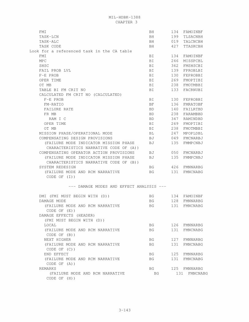
CHAPTER 3MIL-HDBK-1388
3-143
FMI BH 134 FAMOINBF TASK-LCN BH 199 TLSACNBH TASK-ALC BH 019 TALCNCBH TASK CODE BH 427 TTASKCBHLook for a referenced task in the CA table FMI BI 134 FAMOINBF MPC BI 246 MISSPCBL SHSC BI 362 FMSHSCBI FAIL PROB LVL BI 139 FPROBLBI F-E PROB BI 130 FEPROBBI OPER TIME BI 269 FMOPTIBI OT MB BI 238 FMOTMBBI TABLE BI FM CRIT NO BI 133 FACRNUBI CALCULATED FM CRIT NO (CALCULATED) F-E PROB BI 130 FEPROBBI FM-RATIO BF 136 FMRATOBF FAILURE RATE BD 140 FAILRTBD FR MB BD 238 FARAMBBD RAM I C BD 347 RAMINDBD OPER TIME BI 269 FMOPTIBI OT MB BI 238 FMOTMBBI MISSION PHASE/OPERATIONAL MODE BL 247 MPOPLDBL COMPENSATING DESIGN PROVISIONS BJ 049 FMCNARBJ (FAILURE MODE INDICATOR MISSION PHASE BJ 135 FMMPCNBJ CHARACTERISTICS NARRATIVE CODE OF (A)) COMPENSATING OPERATOR ACTION PROVISIONS BJ 050 FMCNARBJ (FAILURE MODE INDICATOR MISSION PHASE BJ 135 FMMPCNBJ CHARACTERISTICS NARRATIVE CODE OF (B)) SYSTEM REDESIGN BG 426 FMNNARBG (FAILURE MODE AND RCM NARRATIVE BG 131 FMNCNABG CODE OF (I))
--- DAMAGE MODES AND EFFECT ANALYSIS ---
DMI (FMI MUST BEGIN WITH (D)) BG 134 FAMOINBF DAMAGE MODE BG 128 FMNNARBG (FAILURE MODE AND RCM NARRATIVE BG 131 FMNCNABG CODE OF (E)) DAMAGE EFFECTS (HEADER) (FMI MUST BEGIN WITH (D)) LOCAL BG 126 FMNNARBG (FAILURE MODE AND RCM NARRATIVE BG 131 FMNCNABG CODE OF (B)) NEXT HIGHER BG 127 FMNNARBG (FAILURE MODE AND RCM NARRATIVE BG 131 FMNCNABG CODE OF (C)) END EFFECT BG 125 FMNNARBG (FAILURE MODE AND RCM NARRATIVE BG 131 FMNCNABG CODE OF (A)) REMARKS BG 125 FMNNARBG (FAILURE MODE AND RCM NARRATIVE BG 131 FMNCNABG CODE OF (H))

CHAPTER 3MIL-HDBK-1388
3-144
PART II
FM CRIT BI 133 FACNUMBI OR FPL BI 139 FPROBLBI LCN BA 199 LSACONXB ALC BA 019 ALTLCNXB FMI BF 134 FAMOINBF TM FGC XB 438 TMFGCDXB LCN NOMENCLATURE XB 201 LCNAMEXB REFERENCE NUMBER HG 337 REFNUMHA CAGE HG 046 CAGECDXH FAIL RATE SOURCE BA 141 FRDATABA
PART III
LCN BI 199 LSACONXB ALC BI 019 ALTLCNXB PART F-RATE BD 140 FAILRTBD RAM I C BD 347 RAMINDBD MB BD 238 FARAMBBD OP TIME BI 269 FMOPTIBI MB BI 238 FMOTMBBI MPC BI 246 MISSPCBL SHSC BI 362 FMSHSCBI FMI BI 134 FAMOINBF FEP BI 130 FEPROBBI F-M RATIO BF 136 FMRATOBF TABLE BI F-MODE CRIT BI 133 FACRNUBI CALCULATED F-MODE CRIT (CALCULATED) FEP BI 130 FEPROBBI F-M RATIO BF 136 FMRATOBF PART F-RATE BD 140 FAILRTBD MB BD 238 FARAMBBD RAM I C OF PART F-RATE BD 347 RAMINDBD OPER TIME BI 269 FMOPTIBI MB BI 238 FMOTMBBI TM FGC XB 438 TMFGCDXB

CHAPTER 3MIL-HDBK-1388
3-145
lsa-056

CHAPTER 3MIL-HDBK-1388
3-146

CHAPTER 3MIL-HDBK-1388
3-147

CHAPTER 3MIL-HDBK-1388
3-148
30.35 LSA-058 RELIABILITY AND MAINTAINABILITY ANALYSIS REPORT SPECIFICATION
30.35.1 SELECTION. The LSA-058 summary is selected by mandatory EIAC, StartLCN, LCN TYPE, and UOC; and optional ALC (default is all ALCs), Stop LCN(default is all LCNs subordinate to, and including, the start LCN), RPT PT(default is none), and SELECTION (default is none).
The report selections consist of: a. RPT PT: 1. Enter a (Y) in this field if part 1 is required for the report. 2. Enter a (Y) in this field if part 2 is required for the report. b. SELECTION: (part 1 only) 1. Enter a (Y) in this field if the description of the failure modes and causes are required for the report. 2. Enter a (Y) in this field if the system Redesign Recommendations resulting from the analysis of the failure modes and causes are required for the report. 3. Enter a (Y) in this field if the logistic considerations are required for the report. 4. Enter a (Y) in this field if the RAM Logistics Considerations Narrative resulting from the analysis of the logistic considerations and failure modes are required for the report. Part 2. There are no selections possible.
30.35.2 PROCESSING. a. Part 1, The report will pull the required information from the appropriate tables (BA, BG, B, BI). Either a Failure Mode Criticality Number or a Failure Probability level may be used in the FM Crit or Fail Prob data element, Failure Mode Criticality Numbers should be used wherever possible. b. Part 2, The report will pull the required information from the appropriate tables (B, BI). c. The (P) or (M) preceding the elapsed time values on the output represent predicted and measured, respectively. Measured values are reported wherever possible. d. Each part of the 058 report should start at the top of a new page.
30.35.3 REPORT FORMAT See Figure 3.32
30.35.4 REPORT SEQUENCE. a. Part 1, The report will be sequenced by ascending RAM LCNs then FMIs. b. Part 2, The report will be sequenced by ascending LCNs then FMIs then MPC for each Maintenance Level, the first being crew and the last being depot.
30.35.5 DATA SOURCES. The source of the data appearing on the LSA-058 summaryis depicted below by data table and element codes.
Report Header Table Codes Ded Element Code EIAC XB 096 EIACODXA LCN NOMENCLATURE XB 201 LCNAMEXB START LCN XB 199 LSACONXB ALC XB 019 ALTLCNXB TYPE XB 203 LCNTYPXB
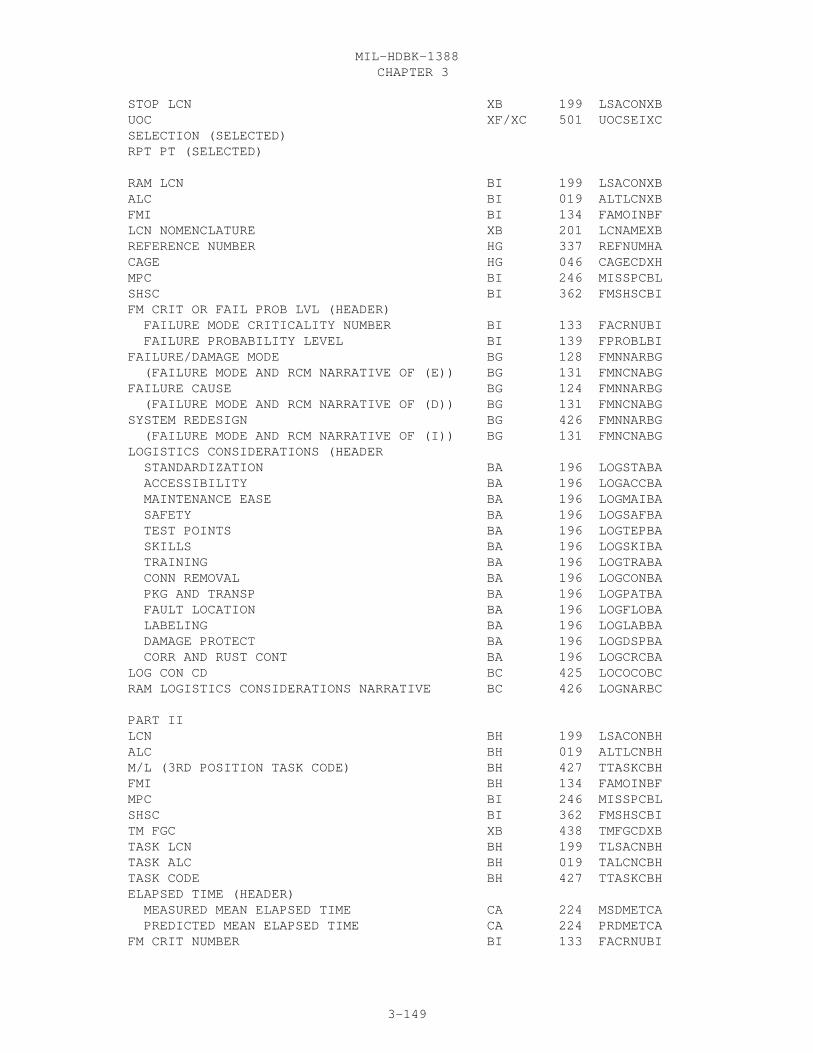
CHAPTER 3MIL-HDBK-1388
3-149
STOP LCN XB 199 LSACONXB UOC XF/XC 501 UOCSEIXC SELECTION (SELECTED) RPT PT (SELECTED)
RAM LCN BI 199 LSACONXB ALC BI 019 ALTLCNXB FMI BI 134 FAMOINBF LCN NOMENCLATURE XB 201 LCNAMEXB REFERENCE NUMBER HG 337 REFNUMHA CAGE HG 046 CAGECDXH MPC BI 246 MISSPCBL SHSC BI 362 FMSHSCBI FM CRIT OR FAIL PROB LVL (HEADER) FAILURE MODE CRITICALITY NUMBER BI 133 FACRNUBI FAILURE PROBABILITY LEVEL BI 139 FPROBLBI FAILURE/DAMAGE MODE BG 128 FMNNARBG (FAILURE MODE AND RCM NARRATIVE OF (E)) BG 131 FMNCNABG FAILURE CAUSE BG 124 FMNNARBG (FAILURE MODE AND RCM NARRATIVE OF (D)) BG 131 FMNCNABG SYSTEM REDESIGN BG 426 FMNNARBG (FAILURE MODE AND RCM NARRATIVE OF (I)) BG 131 FMNCNABG LOGISTICS CONSIDERATIONS (HEADER STANDARDIZATION BA 196 LOGSTABA ACCESSIBILITY BA 196 LOGACCBA MAINTENANCE EASE BA 196 LOGMAIBA SAFETY BA 196 LOGSAFBA TEST POINTS BA 196 LOGTEPBA SKILLS BA 196 LOGSKIBA TRAINING BA 196 LOGTRABA CONN REMOVAL BA 196 LOGCONBA PKG AND TRANSP BA 196 LOGPATBA FAULT LOCATION BA 196 LOGFLOBA LABELING BA 196 LOGLABBA DAMAGE PROTECT BA 196 LOGDSPBA CORR AND RUST CONT BA 196 LOGCRCBA LOG CON CD BC 425 LOCOCOBC RAM LOGISTICS CONSIDERATIONS NARRATIVE BC 426 LOGNARBC
PART II LCN BH 199 LSACONBH ALC BH 019 ALTLCNBH M/L (3RD POSITION TASK CODE) BH 427 TTASKCBH FMI BH 134 FAMOINBF MPC BI 246 MISSPCBL SHSC BI 362 FMSHSCBI TM FGC XB 438 TMFGCDXB TASK LCN BH 199 TLSACNBH TASK ALC BH 019 TALCNCBH TASK CODE BH 427 TTASKCBH ELAPSED TIME (HEADER) MEASURED MEAN ELAPSED TIME CA 224 MSDMETCA PREDICTED MEAN ELAPSED TIME CA 224 PRDMETCA FM CRIT NUMBER BI 133 FACRNUBI

CHAPTER 3MIL-HDBK-1388
3-150
lsa-058

CHAPTER 3MIL-HDBK-1388
3-151
30.36 LSA-065 MANPOWER REQUIREMENTS CRITERIA (MARC) REPORT SPECIFICATION
30.36.1 SELECTION. The LSA-065 summary is selected by mandatory EIAC, LCN,TYPE, and SERV DES, and optional ALC, STOP LCN, UOC and SSC.
30.36.2 PROCESSING. In order to produce an LSA-065 summary, qualified TaskShave subtask mean man-minutes per person ID must be contained within theselected LCN range.
a. The following formula applies for Mean Time Between Task MaintenanceActions (MTBTMA) for all Task Interval codes except Q, C, P, M, N, and L. Theexceptions have MTBMA calculated by dividing 365 days by the Task Frequency.Therefore, the MB for these exceptions is always "D".
Annual Operating Requirements (1) MTBTMA(i) = Task Frequency(i)
Where: i = Task Codei
N E SUBMMMCDx (2) M-HRS PER i=1 60 PERS ID =
Where: N = Number of Subtasks of Task Code with Mean Minutes per Person Identifier (PID) of PIDx
b. The report displays the system/component Reference Number. Withineach reference number, tasks are displayed by unscheduled/on equipment (TaskInterval Codes F, G and J, and Task Operability Codes A, B, C, D and E);unscheduled/off equipment (Task Interval Codes F, G and J and Task OperabilityCode G); and scheduled (all Task Interval Codes except F, G, J, and Y).
30.36.3 REPORT FORMAT. See Figure 3.33
30.36.4 REPORT SEQUENCE. The report is sequenced by ascending ReferenceNumber/CAGE. Within Reference Number/CAGE by On Equipment Tasks, Offequipment corrective tasks, and Scheduled Tasks. Within Tasks lines of reportdata are sorted in ascending SSC/PERS ID.
30.36.5 DATA SOURCES. The source of data appearing on the LSA-065 summary isdepicted below by data table and element codes.
Report header Table Code DED Element Code
EIAC XB 096 EIACODXA LCN NOMENCLATURE XB 201 LCNAMEXB START LCN XB 199 LSACONXB ALC XB 019 ALTLCNXB TYPE XB 203 LCNTYPXB STOP LCN XB 199 LSACONXB UOC XF/XC 501 UOCSEIXC SERV DES CA 427 TASKCDCA SSC CD 387 SKSPCDGA
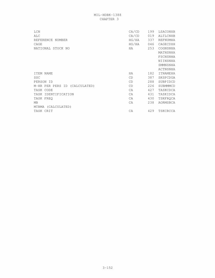
CHAPTER 3MIL-HDBK-1388
3-152
LCN CA/CD 199 LSACONXB ALC CA/CD 019 ALTLCNXB REFERENCE NUMBER HG/HA 337 REFNUMHA CAGE HG/HA 046 CAGECDXH NATIONAL STOCK NO HA 253 COGNSNHA MATNSNHA FSCNSNHA NIINSNHA SMMNSNHA ACTNSNHA ITEM NAME HA 182 ITNAMEHA SSC CD 387 SKSPCDGA PERSON ID CD 288 SUBPIDCD M-HR PER PERS ID (CALCULATED) CD 226 SUBMMMCD TASK CODE CA 427 TASKCDCA TASK IDENTIFICATION CA 431 TASKIDCA TASK FREQ CA 430 TSKFRQCA MB CA 238 AORMSBCA MTBMA (CALCULATED) TASK CRIT CA 429 TSKCRCCA

CHAPTER 3MIL-HDBK-1388
3-153
LSA-065
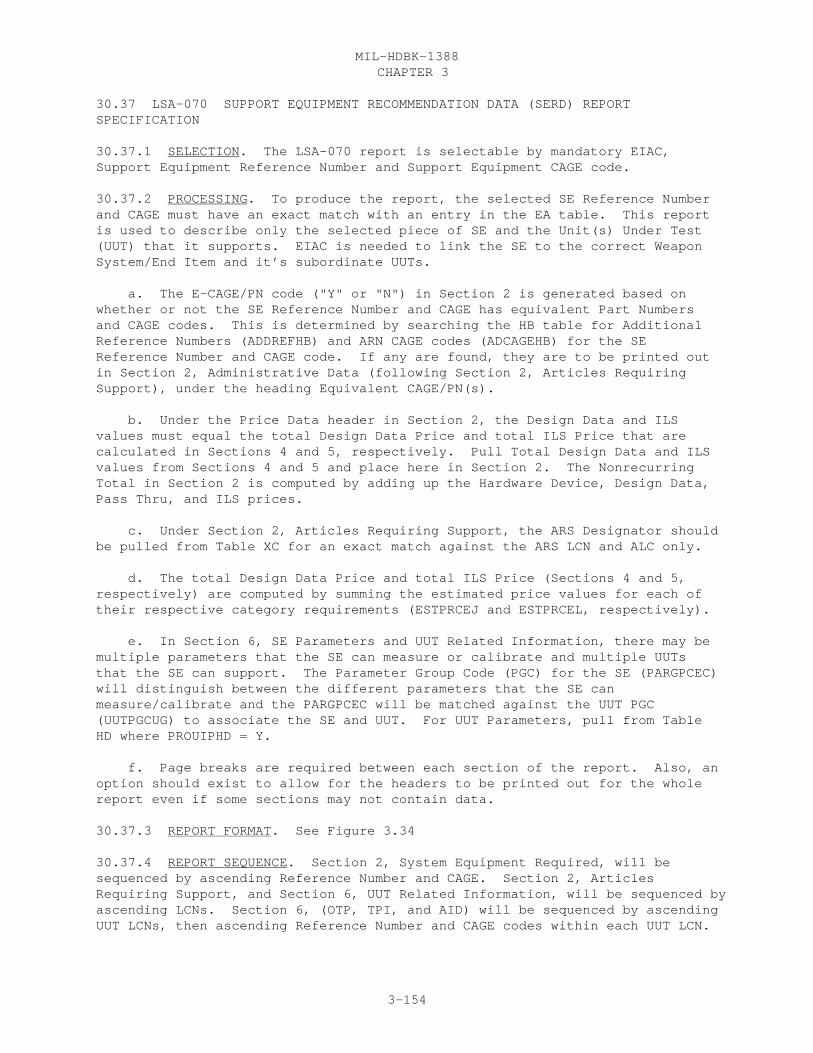
CHAPTER 3MIL-HDBK-1388
3-154
30.37 LSA-070 SUPPORT EQUIPMENT RECOMMENDATION DATA (SERD) REPORTSPECIFICATION
30.37.1 SELECTION. The LSA-070 report is selectable by mandatory EIAC,Support Equipment Reference Number and Support Equipment CAGE code.
30.37.2 PROCESSING. To produce the report, the selected SE Reference Numberand CAGE must have an exact match with an entry in the EA table. This reportis used to describe only the selected piece of SE and the Unit(s) Under Test(UUT) that it supports. EIAC is needed to link the SE to the correct WeaponSystem/End Item and it’s subordinate UUTs.
a. The E-CAGE/PN code ("Y" or "N") in Section 2 is generated based onwhether or not the SE Reference Number and CAGE has equivalent Part Numbersand CAGE codes. This is determined by searching the HB table for AdditionalReference Numbers (ADDREFHB) and ARN CAGE codes (ADCAGEHB) for the SEReference Number and CAGE code. If any are found, they are to be printed outin Section 2, Administrative Data (following Section 2, Articles RequiringSupport), under the heading Equivalent CAGE/PN(s).
b. Under the Price Data header in Section 2, the Design Data and ILSvalues must equal the total Design Data Price and total ILS Price that arecalculated in Sections 4 and 5, respectively. Pull Total Design Data and ILSvalues from Sections 4 and 5 and place here in Section 2. The NonrecurringTotal in Section 2 is computed by adding up the Hardware Device, Design Data,Pass Thru, and ILS prices.
c. Under Section 2, Articles Requiring Support, the ARS Designator shouldbe pulled from Table XC for an exact match against the ARS LCN and ALC only.
d. The total Design Data Price and total ILS Price (Sections 4 and 5,respectively) are computed by summing the estimated price values for each oftheir respective category requirements (ESTPRCEJ and ESTPRCEL, respectively).
e. In Section 6, SE Parameters and UUT Related Information, there may bemultiple parameters that the SE can measure or calibrate and multiple UUTsthat the SE can support. The Parameter Group Code (PGC) for the SE (PARGPCEC)will distinguish between the different parameters that the SE canmeasure/calibrate and the PARGPCEC will be matched against the UUT PGC(UUTPGCUG) to associate the SE and UUT. For UUT Parameters, pull from TableHD where PROUIPHD = Y.
f. Page breaks are required between each section of the report. Also, anoption should exist to allow for the headers to be printed out for the wholereport even if some sections may not contain data.
30.37.3 REPORT FORMAT. See Figure 3.34
30.37.4 REPORT SEQUENCE. Section 2, System Equipment Required, will besequenced by ascending Reference Number and CAGE. Section 2, ArticlesRequiring Support, and Section 6, UUT Related Information, will be sequenced byascending LCNs. Section 6, (OTP, TPI, and AID) will be sequenced by ascendingUUT LCNs, then ascending Reference Number and CAGE codes within each UUT LCN.

CHAPTER 3MIL-HDBK-1388
3-155
30.37.5 DATA SOURCES. The source of data appearing on the LSA-070summary is depicted below by data table and element codes.
Report Header Table Code DED Element Code EIAC XB 096 EIACODXA MANUFACTURER’S PART NUMBER EA 337 SEREFNEA MANUFACTURER’S CAGE CODE EA 046 SECAGEEA
SECTION 1. DESCRIPTION OF RQMTS (HEADER) FUNCTIONAL ANALYSIS EE 147 SEQNAREE (SUPPORT EQUIPMENT NARRATIVE CODE OF A) EE 414 SENARCEE DESCRIPTION AND FUNCTION EE 078 SEQNAREE (SUPPORT EQUIPMENT NARRATIVE CODE OF B) EE 414 SENARCEE SE NON-PROLIFERATION EFFORT EE 415 SEQNAREE (SUPPORT EQUIPMENT NARRATIVE CODE OF C) EE 414 SENARCEE CHARACTERISTICS OF SE EE 044 SEQNAREE (SUPPORT EQUIPMENT NARRATIVE CODE OF D) EE 414 SENARCEE INSTALLATION FACTORS OR OTHER FACILITIES EE 169 SEQNAREE (SUPPORT EQUIPMENT NARRATIVE CODE OF E) EE 414 SENARCEE ADDITIONAL SKILLS AND SPECIAL TRAINING EE 008 SEQNAREE REQUIREMENTS (SUPPORT EQUIPMENT NARRATIVE CODE OF F) EE 414 SENARCEE SERD NO. EF 416 SERDNOEF REV EF 360 SRDREVEF REV DT EF 071 DTRVSBEF STATUS EF 404 STATUSEF SE ITEM NAME HA 182 ITNAMEHA CAGE EA 046 SECAGEEA MFR’S PART NUMBER EA 337 SEREFNEA
SECTION 2. ADMINISTRATIVE DATA (HEADER) LCN HG 199 LSACONXB ALC HG 019 ALTLCNXB PREPARING ACTIVITY EA 294 PREATYEA ORIG DT EF 071 INTSUBEF CAGE EA 046 SECAGEEA MFR’S PART NUMBER EA 337 SEREFNEA E-CAGE/PN (GENERATED) (ARN CAGE CODE) HB 046 ADCAGEHB (ADDITIONAL REFERENCE NUMBER) HB 006 ADDREFHB EA DESIGNATOR EA 183 ENDARTEA EA NAME HA 188 ITNAMEHA ACTION DATE EF 071 DTGVDSEF GOVT DESIGNATOR EA 149 GOVDESEA SE FULL ITEM NAME EA 412 FLITNMEA SIASCN EA 401 SIASCNEA SKETCH EA 383 SKETCHEA NATIONAL STOCK NUMBER HA 253 COGNSNHA SMMNSNHA MATNSNHA FSCNSNHA NIINSNHA

CHAPTER 3MIL-HDBK-1388
3-156
ACTNSNHA ALT NSN (GENERATED) (ALTERNATE NSN) EH 253 ALTFSCEH ALTNIIEH CONTRACT NUMBER EA 055 CNTRNOEA RESPONSIBLE AGENCY (HEADER) NAME EA 002 AQDCOFEA CODE EA 198 LGDCOFEA PE EA 301 PROELEEA PSICP EA 303 PSICPOEA ICC EA 177 SEICCDEA CFE/GFE EA 056 CFEGFEEA CAL ITEM EA 038 CALITMEA CAL REQD EA 040 CALRQDEA SER EA 376 SERDESEA USER EA 376 USESEREA CTIC HA 058 CTICODHA SM&R EA 389 SMRCSEEA TEC EA 480 TYPEEQEA TECHEVAL EA 435 TECEVLEA TECH MANUAL CODES EA 441 TMRQCDEA PROD LEAD TIME HA 299 PRDLDTHA 1ST ARTICLE EA 071 DATFADEA SPCL MGT EA 393 SPMGNTEA MGT PLAN EA 216 MGTPLNEA USABLE ON CODES XC 501 UOCSEIXC PHYSICAL DATA (HEADER) DIMENSIONS (HEADER) OPERATING LN EA 268 OPLENGEA OPERATING WD EA 268 OPWIDTEA OPERATING HT EA 268 OPRHGTEA OPERATING UM EA 491 LWHOUMEA STORAGE LN EA 405 STOLENEA STORAGE WD EA 405 STOWDTEA STORAGE HT EA 405 STOHGTEA STORAGE UM EA 491 LWHSUMEA SHIPPING LN EA 419 SESHPLEA SHIPPING WD EA 419 SESHPWEA SHIPPING HT EA 419 SESHPHEA SHIPPING UM EA 491 UMSHIPEA OPERATING WT EA 270 OPRWGTEA OPERATING WT UM EA 491 WGTOUMEA STORAGE WT EA 406 STOWGTEA STORAGE WT UM EA 491 WGTSUMEA SHIPPING WT EA 420 SESHWTEA SHIPPING WT UM EA 491 UMSEWTEA SHIPPING MODES JD 475 WHTRLOJD (TRANSPORTED END ITEM NARRATIVE CODE OF E) JD 474 TREINCJD PRICE DATA (HEADER) HDWR DEV EA 153 HDWRPREA DESIGN DATA (CALCULATED) PASS THRU EA 285 PASTHREA
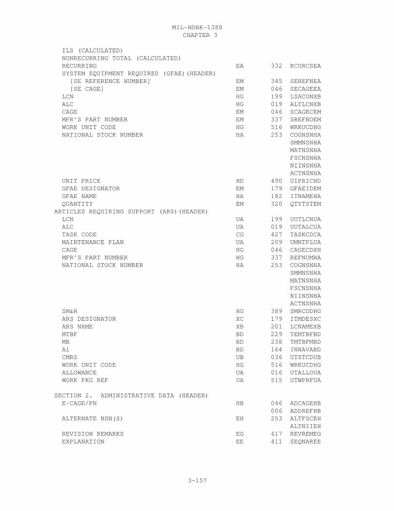
CHAPTER 3MIL-HDBK-1388
3-157
ILS (CALCULATED) NONRECURRING TOTAL (CALCULATED) RECURRING EA 332 RCURCSEA SYSTEM EQUIPMENT REQUIRED (GFAE)(HEADER) [SE REFERENCE NUMBER] EM 345 SEREFNEA [SE CAGE] EM 046 SECAGEEA LCN HG 199 LSACONXB ALC HG 019 ALTLCNXB CAGE EM 046 SCAGECEM MFR’S PART NUMBER EM 337 SREFNOEM WORK UNIT CODE HG 516 WRKUCDHG NATIONAL STOCK NUMBER HA 253 COGNSNHA SMMNSNHA MATNSNHA FSCNSNHA NIINSNHA ACTNSNHA UNIT PRICE HD 490 UIPRICHD GFAE DESIGNATOR EM 179 GFAEIDEM GFAE NAME HA 182 ITNAMEHA QUANTITY EM 320 QTYTSTEM ARTICLES REQUIRING SUPPORT (ARS)(HEADER) LCN UA 199 UUTLCNUA ALC UA 019 UUTALCUA TASK CODE CG 427 TASKCDCA MAINTENANCE PLAN UA 209 UMNTPLUA CAGE HG 046 CAGECDXH MFR’S PART NUMBER HG 337 REFNUMHA NATIONAL STOCK NUMBER HA 253 COGNSNHA SMMNSNHA MATNSNHA FSCNSNHA NIINSNHA ACTNSNHA SM&R HG 389 SMRCODHG ARS DESIGNATOR XC 179 ITMDESXC ARS NAME XB 201 LCNAMEXB MTBF BD 229 TEMTBFBD MB BD 238 TMTBFMBD Ai BD 164 INHAVABD CMRS UB 036 UTSTCDUB WORK UNIT CODE HG 516 WRKUCDHG ALLOWANCE UA 016 UTALLOUA WORK PKG REF UA 515 UTWPRFUA
SECTION 2. ADMINISTRATIVE DATA (HEADER) E-CAGE/PN HB 046 ADCAGEHB 006 ADDREFHB ALTERNATE NSN(S) EH 253 ALTFSCEH ALTNIIEH REVISION REMARKS EG 417 REVREMEG EXPLANATION EE 411 SEQNAREE

CHAPTER 3MIL-HDBK-1388
3-158
(SUPPORT EQUIPMENT NARRATIVE CODE OF G) EE 414 SENARCEE
SECTION 3. SUPERSEDURE/DELETION/ DISTRIBUTION DATA (HEADER) SUPERSEDURE DATA (HEADER) SERDS SUPERSEDED BY THIS SERD (HEADER) SERDS THAT SUPERSEDE THIS SERD (HEADER) [SUPERCEDURE TYPE] EK 408 SUTYPEEK SERD NO EK 416 SUSRNOEK REASON FOR SUPERSEDURE EK 327 REASUPEK CAGE EK 046 SPRCAGEK MFR’S PART NUMBER EK 337 SPRREFEK SE ITEM NAME EK 182 SUPITNEK IC EK 172 ICCODEEK REASON FOR DELETION EK 327 REASUPEK ALLOCATION DATA (HEADER) ALLOWANCE EB 016 ALDCNMEB SIDN EB 015 ALSTIDEB MLF EB 015 ALMLVLEB LVC EB 015 ALLVCDEB CUST CODE EA 069 CUSTCDEA DESIG DESCRIP EB 015 ALDNDSEB ALLOWANCE RANGE EB 015 ALORG1EB ALORG2EB ALORG3EB ALORG4EB ALORG5EB ALORG6EB ALORG7EB ALORG8EB ALORG9EB ALRG10EB (END ITEM DENSITIES - SELECTED) MOBILE FACILITY EA 248 MOBFACEA SPARE FACTOR EA 390 SPRFACEA REVOLVING ASSETS EA 361 REVASSEA SPECIFIC AUTHORIZATIONS (HEADER) NUMBER OF ACTIVITIES ED 399 NUMACTED TYPE OF ACTIVITY ED 399 TYPACTED NAME/LOCATION OF ACTIVITY ED 399 ACTNAMED QTY PER ACTIVITY ED 399 SEQTYAED
SECTION 4. DESIGN DATA (HEADER) REQUIREMENTS (HEADER) DESIGN DATA CATEGORIES (HEADER) DDCC EJ 079 DSNDATEJ CONTRACTOR RECOMMENDED EJ 057 CNTRECEJ GOVERNMENT REQUIRED EJ 150 GOVRQDEJ ESTIMATED PRICE EJ 101 ESTPRCEJ SCOPE EJ 365 DDCCSCEJ DESIGN DATA PRICE (CALCULATED)
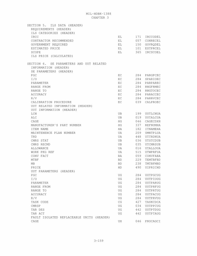
CHAPTER 3MIL-HDBK-1388
3-159
SECTION 5. ILS DATA (HEADER) REQUIREMENTS (HEADER) ILS CATEGORIES (HEADER) IRCC EL 171 IRCCODEL CONTRACTOR RECOMMENDED EL 057 CONRECEL GOVERNMENT REQUIRED EL 150 GOVRQDEL ESTIMATED PRICE EL 101 ESTPRCEL SCOPE EL 365 IRCSCOEL ILS PRICE (CALCULATED)
SECTION 6. SE PARAMETERS AND UUT RELATED INFORMATION (HEADER) SE PARAMETERS (HEADER) PGC EC 284 PARGPCEC I/O EC 284 SPARIOEC PARAMETER EC 284 PARPAREC RANGE FROM EC 284 RNGFRMEC RANGE TO EC 284 RNGTOCEC ACCURACY EC 284 PARACCEC R/V EC 284 PARRVCEC CALIBRATION PROCEDURE EC 039 CALPROEC UUT RELATED INFORMATION (HEADER) UUT INFORMATION (HEADER) LCN UB 199 UUTLCNUA ALC UB 019 UUTALCUA CAGE HG 046 CAGECDXH MANUFACTURER’S PART NUMBER HG 337 REFNUMHA ITEM NAME HA 182 ITNAMEHA MAINTENENCE PLAN NUMBER UA 209 UMNTPLUA TRD UA 448 UTTRDNUA CMRS STAT UB 036 UTSTCDUB CMRS RECMD UB 035 UTCMRSUB ALLOWANCE UA 016 UTALLOUA WORK PKG REF UA 515 UTWPRFUA CONV FACT BA 059 CONVFABA MTBF BD 229 TEMTBFBD MB BD 238 TMTBFMBD PRICE HD 490 UIPRICHD UUT PARAMETERS (HEADER) PGC UG 284 UUTPGCUG I/O UG 284 UUTPIOUG PARAMETER UG 284 UUTPARUG RANGE FROM UG 284 UUTPRFUG RANGE TO UG 284 UUTPRTUG ACCURACY UG 284 UUTPACUG R/V UG 284 UUTPRVUG TASK CODE CG 427 TASKCDCA CMRSP UG 034 UUTPPCUG TAR DES UG 442 UUTPTDUG TAR ACT UG 442 UUTPTAUG FAULT ISOLATED REPLACEABLE UNITS (HEADER) CAGE UH 046 PROCAGCI
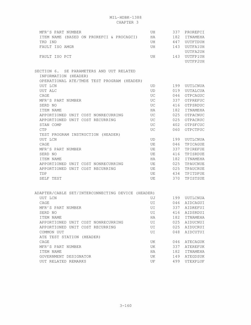
CHAPTER 3MIL-HDBK-1388
3-160
MFR’S PART NUMBER UH 337 PROREFCI ITEM NAME (BASED ON PROREFCI & PROCAGCI) HA 182 ITNAMEHA TRD IND UH 447 UUTFTDUH FAULT ISO AMGR UH 143 UUTFA1UH UUTFA2UH FAULT ISO PCT UH 143 UUTFP1UH UUTFP2UH
SECTION 6. SE PARAMETERS AND UUT RELATED INFORMATION (HEADER) OPERATIONAL ATE/TMDE TEST PROGRAM (HEADER) UUT LCN UD 199 UUTLCNUA UUT ALC UD 019 UUTALCUA CAGE UC 046 OTPCAGUC MFR’S PART NUMBER UC 337 OTPREFUC SERD NO UC 416 OTPSRDUC ITEM NAME HA 182 ITNAMEHA APPORTIONED UNIT COST NONRECURRING UC 025 OTPACNUC APPORTIONED UNIT COST RECURRING UC 025 OTPACRUC STAN COMP UC 402 OTPSFCUC CTP UC 060 OTPCTPUC TEST PROGRAM INSTRUCTION (HEADER) UUT LCN UD 199 UUTLCNUA CAGE UE 046 TPICAGUE MFR’S PART NUMBER UE 337 TPIREFUE SERD NO UE 416 TPISRDUE ITEM NAME HA 182 ITNAMEHA APPORTIONED UNIT COST NONRECURRING UE 025 TPAUCNUE APPORTIONED UNIT COST RECURRING UE 025 TPAUCRUE TDP UE 434 TPITDPUE SELF TEST UE 370 TPISTSUE
ADAPTER/CABLE SET/INTERCONNECTING DEVICE (HEADER) UUT LCN UJ 199 UUTLCNUA CAGE UI 046 AIDCAGUI MFR’S PART NUMBER UI 337 AIDREFUI SERD NO UI 416 AIDSRDUI ITEM NAME HA 182 ITNAMEHA APPORTIONED UNIT COST NONRECURRING UI 025 AIDUCNUI APPORTIONED UNIT COST RECURRING UI 025 AIDUCRUI COMMON UUT UI 048 AIDCUTUI ATE TEST STATION (HEADER) CAGE UK 046 ATECAGUK MFR’S PART NUMBER UK 337 ATEREFUK ITEM NAME HA 182 ITNAMEHA GOVERNMENT DESIGNATOR UK 149 ATEGDSUK UUT RELATED REMARKS UF 499 UTEXPLUF

CHAPTER 3MIL-HDBK-1388
3-161
LSA-070

CHAPTER 3MIL-HDBK-1388
3-162

CHAPTER 3MIL-HDBK-1388
3-163

CHAPTER 3MIL-HDBK-1388
3-164

CHAPTER 3MIL-HDBK-1388
3-165

CHAPTER 3MIL-HDBK-1388
3-166

CHAPTER 3MIL-HDBK-1388
3-167

CHAPTER 3MIL-HDBK-1388
3-168

CHAPTER 3MIL-HDBK-1388
3-169

CHAPTER 3MIL-HDBK-1388
3-170

CHAPTER 3MIL-HDBK-1388
3-171

CHAPTER 3MIL-HDBK-1388
3-172
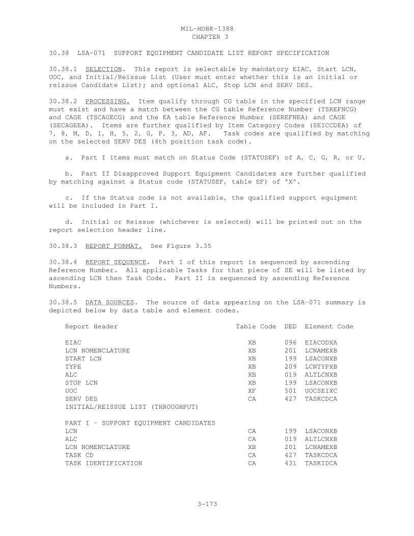
CHAPTER 3MIL-HDBK-1388
3-173
30.38 LSA-071 SUPPORT EQUIPMENT CANDIDATE LIST REPORT SPECIFICATION
30.38.1 SELECTION. This report is selectable by mandatory EIAC, Start LCN,UOC, and Initial/Reissue List (User must enter whether this is an initial orreissue Candidate List); and optional ALC, Stop LCN and SERV DES.
30.38.2 PROCESSING. Item qualify through CG table in the specified LCN rangemust exist and have a match between the CG table Reference Number (TSREFNCG)and CAGE (TSCAGECG) and the EA table Reference Number (SEREFNEA) and CAGE(SECAGEEA). Items are further qualified by Item Category Codes (SEICCDEA) of7, 8, M, D, 1, H, 5, 2, G, P, 3, AD, AF. Task codes are qualified by matchingon the selected SERV DES (4th position task code).
a. Part I items must match on Status Code (STATUSEF) of A, C, G, R, or U.
b. Part II Disapproved Support Equipment Candidates are further qualifiedby matching against a Status code (STATUSEF, table EF) of "X".
c. If the Status code is not available, the qualified support equipmentwill be included in Part I.
d. Initial or Reissue (whichever is selected) will be printed out on thereport selection header line.
30.38.3 REPORT FORMAT. See Figure 3.35
30.38.4 REPORT SEQUENCE. Part I of this report is sequenced by ascendingReference Number. All applicable Tasks for that piece of SE will be listed byascending LCN then Task Code. Part II is sequenced by ascending ReferenceNumbers.
30.38.5 DATA SOURCES. The source of data appearing on the LSA-071 summary isdepicted below by data table and element codes.
Report Header Table Code DED Element Code
EIAC XB 096 EIACODXA LCN NOMENCLATURE XB 201 LCNAMEXB START LCN XB 199 LSACONXB TYPE XB 209 LCNTYPXB ALC XB 019 ALTLCNXB STOP LCN XB 199 LSACONXB UOC XF 501 UOCSEIXC SERV DES CA 427 TASKCDCA INITIAL/REISSUE LIST (THROUGHPUT)
PART I - SUPPORT EQUIPMENT CANDIDATES LCN CA 199 LSACONXB ALC CA 019 ALTLCNXB LCN NOMENCLATURE XB 201 LCNAMEXB TASK CD CA 427 TASKCDCA TASK IDENTIFICATION CA 431 TASKIDCA
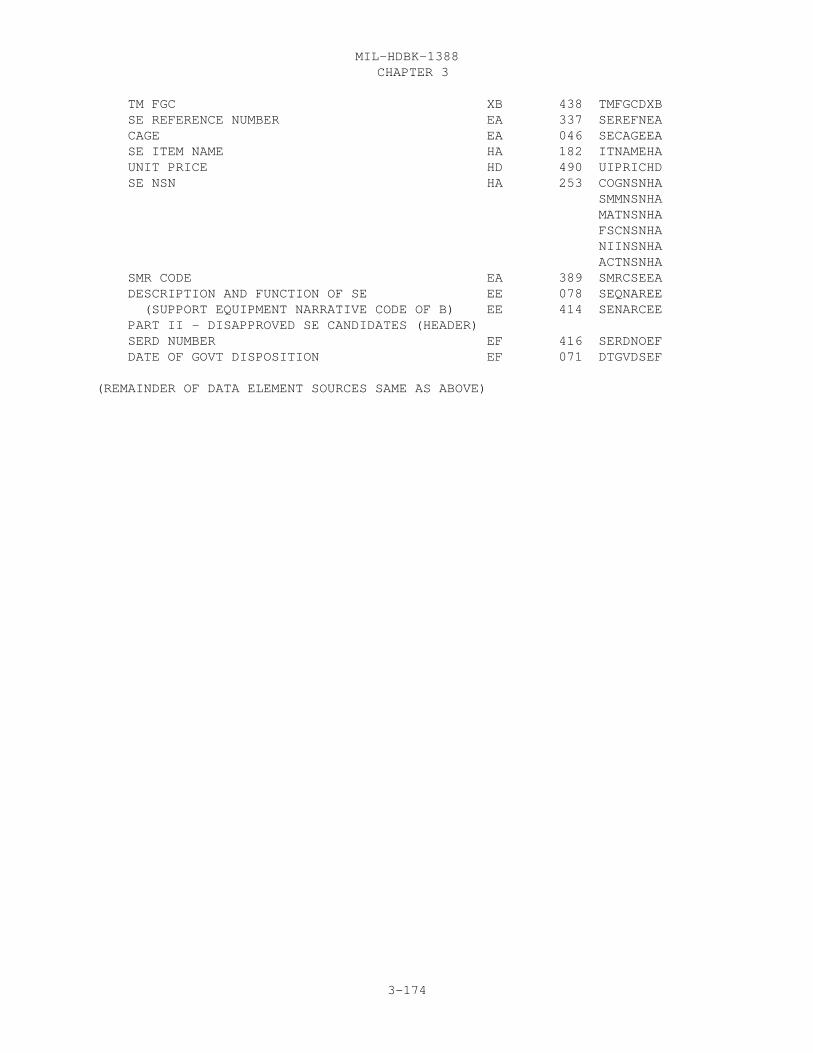
CHAPTER 3MIL-HDBK-1388
3-174
TM FGC XB 438 TMFGCDXB SE REFERENCE NUMBER EA 337 SEREFNEA CAGE EA 046 SECAGEEA SE ITEM NAME HA 182 ITNAMEHA UNIT PRICE HD 490 UIPRICHD SE NSN HA 253 COGNSNHA SMMNSNHA MATNSNHA FSCNSNHA NIINSNHA ACTNSNHA SMR CODE EA 389 SMRCSEEA DESCRIPTION AND FUNCTION OF SE EE 078 SEQNAREE (SUPPORT EQUIPMENT NARRATIVE CODE OF B) EE 414 SENARCEE PART II - DISAPPROVED SE CANDIDATES (HEADER) SERD NUMBER EF 416 SERDNOEF DATE OF GOVT DISPOSITION EF 071 DTGVDSEF
(REMAINDER OF DATA ELEMENT SOURCES SAME AS ABOVE)

CHAPTER 3MIL-HDBK-1388
3-175
lsa-071
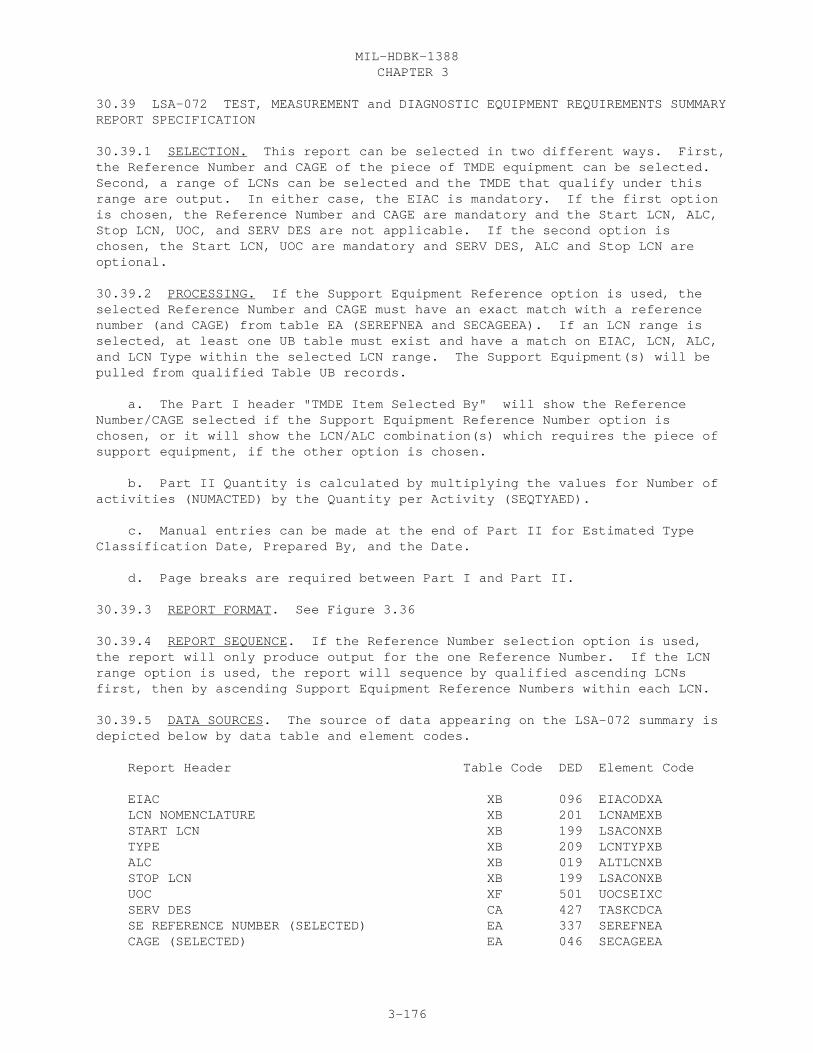
CHAPTER 3MIL-HDBK-1388
3-176
30.39 LSA-072 TEST, MEASUREMENT and DIAGNOSTIC EQUIPMENT REQUIREMENTS SUMMARYREPORT SPECIFICATION
30.39.1 SELECTION. This report can be selected in two different ways. First,the Reference Number and CAGE of the piece of TMDE equipment can be selected. Second, a range of LCNs can be selected and the TMDE that qualify under thisrange are output. In either case, the EIAC is mandatory. If the first optionis chosen, the Reference Number and CAGE are mandatory and the Start LCN, ALC,Stop LCN, UOC, and SERV DES are not applicable. If the second option ischosen, the Start LCN, UOC are mandatory and SERV DES, ALC and Stop LCN areoptional.
30.39.2 PROCESSING. If the Support Equipment Reference option is used, theselected Reference Number and CAGE must have an exact match with a referencenumber (and CAGE) from table EA (SEREFNEA and SECAGEEA). If an LCN range isselected, at least one UB table must exist and have a match on EIAC, LCN, ALC,and LCN Type within the selected LCN range. The Support Equipment(s) will bepulled from qualified Table UB records.
a. The Part I header "TMDE Item Selected By" will show the ReferenceNumber/CAGE selected if the Support Equipment Reference Number option ischosen, or it will show the LCN/ALC combination(s) which requires the piece ofsupport equipment, if the other option is chosen.
b. Part II Quantity is calculated by multiplying the values for Number ofactivities (NUMACTED) by the Quantity per Activity (SEQTYAED).
c. Manual entries can be made at the end of Part II for Estimated TypeClassification Date, Prepared By, and the Date.
d. Page breaks are required between Part I and Part II.
30.39.3 REPORT FORMAT. See Figure 3.36
30.39.4 REPORT SEQUENCE. If the Reference Number selection option is used,the report will only produce output for the one Reference Number. If the LCNrange option is used, the report will sequence by qualified ascending LCNsfirst, then by ascending Support Equipment Reference Numbers within each LCN.
30.39.5 DATA SOURCES. The source of data appearing on the LSA-072 summary isdepicted below by data table and element codes.
Report Header Table Code DED Element Code
EIAC XB 096 EIACODXA LCN NOMENCLATURE XB 201 LCNAMEXB START LCN XB 199 LSACONXB TYPE XB 209 LCNTYPXB ALC XB 019 ALTLCNXB STOP LCN XB 199 LSACONXB UOC XF 501 UOCSEIXC SERV DES CA 427 TASKCDCA SE REFERENCE NUMBER (SELECTED) EA 337 SEREFNEA CAGE (SELECTED) EA 046 SECAGEEA

CHAPTER 3MIL-HDBK-1388
3-177
TMDE ITEM SELECTED BY (HEADER) PART I - TMDE TECHNICAL DESCRIPTION SE REFERENCE NUMBER EA 337 SEREFNEA CAGE EA 046 SECAGEEA ITEM NAME HA 182 ITNAMEHA FULL ITEM NAME EA 412 FLITNMEA DESCRIPTION AND FUNCTION OF SE EE 078 SEQNAREE (SUPPORT EQUIPMENT NARRATIVE CODE OF B) EE 414 SENARCEE I/O EC 284 SPARIOEC PARAMETER EC 284 PARPAREC RANGE FROM EC 284 RNGFRMEC RANGE TO EC 284 RNGTOCEC RANGE ACCURACY EC 284 PARACCEC DEPTH EA 268 OPLENGEA WIDTH EA 268 OPWIDTEA HEIGHT EA 268 OPRHGTEA UM EA 491 LWHOUMEA WEIGHT EA 270 OPRWGTEA UM EA 491 WGTOUMEA MIN VOLTS EI 168 IPOPRGEI MAX VOLTS EI 168 IPSRGMEI AC/DC EI 168 IPACDCEI MAX FREQUENCY EI 168 IPFRMXEI MIN FREQUENCY EI 168 IPRGMXEI PHASE EI 168 IPPHASEI WATTS EI 168 IPPOWREI PERCENT MAX RIPPLE EI 168 IPMXRPEI ITEMS THIS WILL REPLACE (HEADER) SUPERSEDED REFERENCE NUMBER EK 337 SPRREFEK CAGE EK 046 SPRCAGEK SKILL SPECIALTY CODE FOR SE EA 387 SSCOPREA PUBLICATIONS EA 278 OPRMANEA MAINT LEVEL EA 277 RPRLVLEA TMDE RAM CHARACTERISTICS (HEADER) MTBF EA 229 SEMTBFEA MTTR EA 236 SEMTTREA CAL TIME EA 042 CALTIMEA NSN AND RELATED DATA HA 253 COGNSNHA SMMNSNHA MATNSNHA FSCNSNHA NIINSNHA ACTNSNHA TYPE CLASS EA 479 TYPCLSEA LIN HA 193 LINNUMHA LOG CONTROL CODE EA 197 LGCTCDEA SELF TESTING EA 370 SLFTSTEA CAL INTERVAL EA 037 CALINTEA LIFE CYCLE STATUS EA 190 LICYSTEA UNIT COST HD 490 UIPRICHD END ITEM NSN AND RELATED DATA HA 253 COGNSNHA SMMNSNHA MATNSNHA
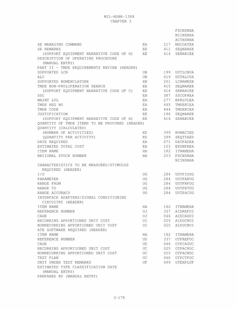
CHAPTER 3MIL-HDBK-1388
3-178
FSCNSNHA NIINSNHA ACTNSNHA SE MANAGING COMMAND EA 217 MGCOATEA SE REMARKS EE 411 SEQNAREE (SUPPORT EQUIPMENT NARRATIVE CODE OF G) EE 414 SENARCEE DESCRIPTION OF OPERATING PROCEDURE (MANUAL ENTRY) PART II - TMDE REQUIREMENTS REVIEW (HEADER) SUPPORTED LCN UB 199 UUTLCNUA ALC UB 019 UUTALCUA SUPPORTED NOMENCLATURE XB 201 LCNAMEXB TMDE NON-PROLIFERATION SEARCH EE 415 SEQNAREE (SUPPORT EQUIPMENT NARRATIVE CODE OF C) EE 414 SENARCEE SSC EA 387 SSCOPREA MAINT LVL EA 277 RPRLVLEA TMDE REG NO EA 445 TMDERIEA TMDE CODE EA 444 TMDERCEA JUSTIFICATION EE 188 SEQNAREE (SUPPORT EQUIPMENT NARRATIVE CODE OF H) EE 414 SENARCEE QUANTITY OF TMDE ITEMS TO BE PROCURED (HEADER) QUANTITY (CALCULATED) (NUMBER OF ACTIVITIES) ED 399 NUMACTED (QUANTITY PER ACTIVITY) ED 399 SEQTYAED DATE REQUIRED EA 071 DATFADEA ESTIMATED TOTAL COST EA 103 EXUNPREA ITEM NAME HA 182 ITNAMEHA NATIONAL STOCK NUMBER HA 253 FSCNSNHA NIINSNHA CHARACTERISTICS TO BE MEASURED/STIMULUS REQUIRED (HEADER) I/O UG 284 UUTPIOUG PARAMETER UG 284 UUTPARUG RANGE FROM UG 284 UUTPRFUG RANGE TO UG 284 UUTPRTUG RANGE ACCURACY UG 284 UUTPACUG INTERFACE ADAPTERS/SIGNAL CONDITIONING CIRCUITRY (HEADER) ITEM NAME HA 182 ITNAMEHA REFERENCE NUMBER UJ 337 AIDREFUI CAGE UJ 046 AIDCAGUI RECURRING APPORTIONED UNIT COST UI 025 AIDUCRUI NONRECURRING APPORTIONED UNIT COST UI 025 AIDUCNUI ATE SOFTWARE REQUIRED (HEADER) ITEM NAME HA 182 ITNAMEHA REFERENCE NUMBER UD 337 OTPREFUC CAGE UD 046 OTPCAGUC RECURRING APPORTIONED UNIT COST UC 025 OTPACRUC NONRECURRING APPORTIONED UNIT COST UC 025 OTPACNUC TEST PLAN UC 060 OTPCTPUC UNIT UNDER TEST REMARKS UF 499 UTEXPLUF ESTIMATED TYPE CLASSIFICATION DATE (MANUAL ENTRY) PREPARED BY (MANUAL ENTRY)

CHAPTER 3MIL-HDBK-1388
3-179
DATE (MANUAL ENTRY)
LSA-072

CHAPTER 3MIL-HDBK-1388
3-180

CHAPTER 3MIL-HDBK-1388
3-181
30.40 LSA-074 SUPPORT EQUIPMENT TOOL LIST REPORT SPECIFICATION
30.40.1 SELECTION. The LSA-074 summary is selectable by mandatory EIAC, StartLCN, LCN Type, UOC; and optional ALC, SERV DES, Stop LCN and ICC-1, ICC-2,ICC-3, ICC-4. Selectable ICCs are limited to Group B (See DED 177) for ICC-1,Group C for ICC-2, code AC for ICC-3, and Group A for ICC-4. If ICCs are notselected, then each part of the report will default to all allowable ICCs,respectively.
30.40.2 PROCESSING. The same qualifying criteria is used for all parts of thereport. As a minimum, there must be at least one LCN within the selectedrange of LCNs with a Task Code (TASKCDCA) qualifying against the selected SERVDES (qualified by 4th position of the Task Code). LCNs are further qualifiedby requiring at least one CG table entry where the Support Equipmentidentified by Reference Number (TSREFNCG) and CAGE (TSCAGECG) matches againstthe selected ICCs (TSREFNCG and TSCAGECG are matched against SEREFNEA andSECAGEEA of table EA in order to access the ICC).
a. Part III, Modified Hand Tools, assumes that a breakdown of the toolexists within the LSAR. This part of the report can only be produced if anLCN, EIAC, and ALC exist on file for the tool and for subordinate items. Ifso, "Make From" items will include those which are subordinate to the tool inLCN structure and which have an Indenture Code greater than that of the tool(e.g., Tool Indenture Code + 1).
b. Within each part of the report, the support equipment item should onlybe listed once. If more than one qualified entry per part occurs for a pieceof support equipment, then all information must be consolidated.
c. Page breaks are required between each part of the report.
30.40.3 REPORT FORMAT. See Figure 3.37
30.40.4 REPORT SEQUENCE. Each part of this report is sequenced by ascendingReference Numbers.
30.40.5 DATA SOURCES. The source of data appearing on the LSA-074 summary isdepicted below by data table and element codes.
Report Header Table Code DED Element Code
EIAC XB 096 EIACODXA LCN NOMENCLATURE XB 201 LCNAMEXB START LCN XB 199 LSACONXB ALC XB 019 ALTLCNXB TYPE XB 209 LCNTYPXB STOP LCN XB 199 LSACONXB UOC XF 501 UOCSEIXC SERV DES CA 427 TASKCDCA ICC - 1 (SELECTED) (GROUP "B" ICCs) EA 177 SEICCDEA ICC - 2 (SELECTED) (GROUP "C" ICCs) EA 177 SEICCDEA ICC - 3 (SELECTED) (ICC CODE "AC" ONLY) EA 177 SEICCDEA ICC - 4 (SELECTED) (GROUP "A" ICCs) EA 177 SEICCDEA

CHAPTER 3MIL-HDBK-1388
3-182
PART I - TOOLS IN INVENTORY (HEADER) REFERENCE NUMBER CG 337 TSREFNCG CAGE CG 046 TSCAGECG ITEM NAME HA 182 ITNAMEHA ACQ DEC OFFICE EA 002 AQDCOFEA SERD NUMBER EF 416 SERDNOEF NSN AND RELATED DATA HA 253 COGNSNHA SMMNSNHA MATNSNHA FSCNSNHA NIINSNHA ACTNSNHA MAINT LEVEL CG 427 TASKCDCA (3RD PART II - TOOLS IN INVENTORY BUT NOT POSITION) ASSIGNED TO A GAINING UNIT (HEADER) SIASCN EA 401 SIASCNEA SKETCH EA 383 SKETCHEA PART III - MODIFIED HAND TOOLS (HEADER) MAKE FROM (HEADER) (INDENTURE CODE) HG 162 INDCODHG (TOOL LCN AND SUBORDINATE LCNs) HG 199 LSACONXB (EIAC) HG 096 EIACODXA (ALC) HG 019 ALTLCNXB REFERENCE NUMBER HG 337 REFNUMHA CAGE HG 046 CAGECDXH PART IV - PECULIAR TOOLS REQUIRING DEVELOPMENT (HEADER) REFERENCE NUMBER CG 337 TSREFNCG CAGE CG 046 TSCAGECG

CHAPTER 3MIL-HDBK-1388
3-183
LSA-074

CHAPTER 3MIL-HDBK-1388
3-184

CHAPTER 3MIL-HDBK-1388
3-185
30.41 LSA-075 CONSOLIDATED MANPOWER, PERSONNEL AND TRAINING REPORTREPORT SPECIFICATION
30.41.1 SELECTION. The LSA-075 summary is selectable by mandatory EIAC, StartLCN, LCN Type, UOC; and optional SERV DES, ALC, Stop LCN, Maintenance Levels,Skill Specialty Code, and Available M-Hrs Peace/War Indicator (default ispeace).
30.41.2 PROCESSING. The same qualifying criteria is used for both Parts I andII. Task codes are qualified by matching on selected SERV DES (4th position oftask code) and on selected Maintenance Levels (3rd position task code). As aminimum, there must be an exact match in table XB with the selected EIAC, LCN,and ALC. If a Skill Specialty Code is selected, an exact match must be made intable GA or GB.
a. Section I, Manpower and Personnel Summary, requires at least oneexisting GA table and CD table on file.
b. Available Man-Hours of 0.00 are significant as opposed to blank valueswhich depicts no data being on file for that element. If Actual Man-Hours canbe calculated, then the Available Man-Hours will be printed even if it isblank.
c. Actual Man-Hours are calculated by summing all mean man-minutes(SUBMMMCD) for a given SSC at a given Maintenance Level across all applicabletasks at the Start LCN and all subordinate LCNs, then dividing by 60.Modified SSCs (MDCSSCGB) entries in Table CD take precedence over SSCs(SKSPCDGA).
d. Actual Quantity of an SSC at a given Maintenance Level can only becalculated correctly if a unique Person ID has been assigned to eachmaintenance person and that relationship is carried out for all tasksthroughout the system at or subordinate to the Start LCN. If so, it is simplya matter of counting the different number of Person IDs for a given SSC at agiven Maintenance Level. If not, the same Person ID could be assigned to twodifferent personnel in different tasks, or the same person could be assigneddifferent Person IDs from task to task. Either way, a correct value forActual Quantity cannot be calculated.
e. Section II requires at least one existing GB table be on file.
f. A page break is required between sections.
30.41.3 REPORT FORMAT. See Figure 3.38
30.41.4 REPORT SEQUENCE. Section 1 is sequenced by ascending SSC, then bymaintenance level within each SSC. Section 2 is sequenced by ascendingOriginal SSC, then by ascending New SSC.
30.41.5 DATA SOURCES. The source of data appearing on the LSA-075 summary isdepicted below by data table and element codes.

CHAPTER 3MIL-HDBK-1388
3-186
Report Header Table Code DED Element Code EIAC XB 096 EIACODXA LCN NOMENCLATURE XB 201 LCNAMEXB START LCN XB 199 LSACONXB TYPE XB 203 LCNTYPXB ALC XB 019 ALTLCNXB UOC XF 501 UOCSEIXC SERV DES CA 427 TASKCDCA MAINT LVLS (SELECTED) CA 427 TASKCDCA SSC (SELECTED) (EXISTING SSC) GA 395 SKSPCDGA (MODIFIED/NEW SSC) GB 264 MDCSSCGB AVAILABLE M-H PEACE/WAR (SELECTED)
SECTION I - MANPOWER AND PERSONNEL SUMMARY (HEADER) LCN CA 199 LSACONXB ALC CA 019 ALTLCNXB LCN NOMENCLATURE XB 201 LCNAMEXB SSC CD 387 SKSPCDGA MAINTENANCE LEVEL CA 427 TASKCDCA AVAIL M-H AE 028 AVAIMHAE ACTUAL M-H (CALCULATED) AVAIL QTY AE 324 QTYAVAAE ACTUAL QTY (CALCULATED) SECTION II - NEW OR MODIFIED SKILL AND TRAINING REQUIREMENTS (HEADER) ORIGINAL SSC GA 387 SKSPCDGA ORIGINAL SLC GA 386 SKLVCDGA NEW/MOD SSC GB 257 MDCSSCGB NEW/MOD SLC GB 386 MDSCLCGB DUTY POSITION REQUIRING NEW/MOD SKILL GB 092 DPRNRSGB RECOMMENDED RANK/RATE/GRADE-MIL RANK GB 330 RPPMILGB RECOMMENDED RANK/RATE/GRADE-CIVIL GRADE GB 330 RPPCIVGB SECURITY CLEARANCE GB 369 SCRSSCGB TEST SCORE GB 449 SSCTESGB NEW OR MODIFIED SKILL REQUIREMENTS GC 007 NMSNARGC (NEW/MODIFIED SKILL NARRATIVE CODE OF A) GC 256 NMSNCDGC EDUCATIONAL QUALIFICATIONS GC 094 NMSNARGC (NEW/MODIFIED SKILL NARRATIVE CODE OF B) GC 256 NMSNCDGC SKILL JUSTIFICATION GC 188 NMSNARGC (NEW/MODIFIED SKILL NARRATIVE CODE OF C) GC 256 NMSNCDGC ADDITIONAL TRAINING REQUIREMENTS GC 012 NMSNARGC (NEW/MODIFIED SKILL NARRATIVE CODE OF D) GC 256 NMSNCDGC PHYSICAL AND MENTAL REQUIREMENTS (HEADER) LCN GE 199 LSACONXB ALC GE 019 ALTLCNXB TASK CD GE 427 TASKCDCA SUBTASK NO GE 407 SUBNUMCB PERSON ID GE 288 SUBPIDCD NARRATIVE GE 372 PAMENRGE

CHAPTER 3MIL-HDBK-1388
3-187
LSA-075

CHAPTER 3MIL-HDBK-1388
3-188
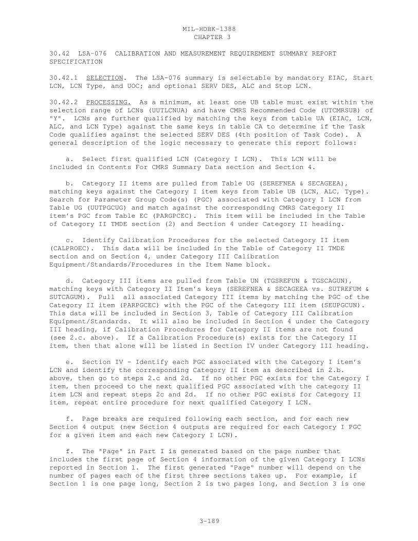
CHAPTER 3MIL-HDBK-1388
3-189
30.42 LSA-076 CALIBRATION AND MEASUREMENT REQUIREMENT SUMMARY REPORTSPECIFICATION
30.42.1 SELECTION. The LSA-076 summary is selectable by mandatory EIAC, StartLCN, LCN Type, and UOC; and optional SERV DES, ALC and Stop LCN.
30.42.2 PROCESSING. As a minimum, at least one UB table must exist within theselection range of LCNs (UUTLCNUA) and have CMRS Recommended Code (UTCMRSUB) of"Y". LCNs are further qualified by matching the keys from table UA (EIAC, LCN,ALC, and LCN Type) against the same keys in table CA to determine if the TaskCode qualifies against the selected SERV DES (4th position of Task Code). Ageneral description of the logic necessary to generate this report follows:
a. Select first qualified LCN (Category I LCN). This LCN will beincluded in Contents For CMRS Summary Data section and Section 4.
b. Category II items are pulled from Table UG (SEREFNEA & SECAGEEA),matching keys against the Category I item keys from Table UB (LCN, ALC, Type).Search for Parameter Group Code(s) (PGC) associated with Category I LCN fromTable UG (UUTPGCUG) and match against the corresponding CMRS Category IIitem’s PGC from Table EC (PARGPCEC). This item will be included in the Tableof Category II TMDE section (2) and Section 4 under Category II heading.
c. Identify Calibration Procedures for the selected Category II item(CALPROEC). This data will be included in the Table of Category II TMDEsection and on Section 4, under Category III CalibrationEquipment/Standards/Procedures in the Item Name block.
d. Category III items are pulled from Table UN (TGSREFUN & TGSCAGUN),matching keys with Category II Item’s keys (SEREFNEA & SECAGEEA vs. SUTREFUM &SUTCAGUM). Pull all associated Category III items by matching the PGC of theCategory II item (PARPGCEC) with the PGC of the Category III item (SEUPGCUN).This data will be included in Section 3, Table of Category III CalibrationEquipment/Standards. It will also be included in Section 4 under the CategoryIII heading, if Calibration Procedures for Category II items are not found(see 2.c. above). If a Calibration Procedure(s) exists for the Category IIitem, then that alone will be listed in Section IV under Category III heading.
e. Section IV - Identify each PGC associated with the Category I item’sLCN and identify the corresponding Category II item as described in 2.b.above, then go to steps 2.c and 2d. If no other PGC exists for the Category Iitem, then proceed to the next qualified PGC associated with the category IIitem LCN and repeat steps 2c and 2d. If no other PGC exists for Category IIitem, repeat entire procedure for next qualified Category I LCN.
f. Page breaks are required following each section, and for each newSection 4 output (new Section 4 outputs are required for each Category I PGCfor a given item and each new Category I LCN).
f. The "Page" in Part I is generated based on the page number thatincludes the first page of Section 4 information of the given Category I LCNsreported in Section 1. The first generated "Page" number will depend on thenumber of pages each of the first three sections takes up. For example, ifSection 1 is one page long, Section 2 is two pages long, and Section 3 is one

CHAPTER 3MIL-HDBK-1388
3-190
page long, then the first generated "Page" number (for the first LCN bysequence) would be five (sum of Sections 1, 2, and 3 page numbers plus one).The "Page" numbers for the succeeding Section 1 LCNs is equal to the priorCategory I item’s "Page" number plus the total pages for Section IV of theprior Category I item (i.e., Section 4 for 1st item is 2 pages, "Page" =5+2 = 7 for 2nd Category I item).
30.42.3 REPORT FORMAT. See Figure 3.39
30.42.4 REPORT SEQUENCE. All Category I items will be listed in Section I,then all Category II items will be listed in Section II before proceeding toSection III and listing all Category III items. Section IV must be sequencedaccording to the "Page" number listed in Section I for the correspondingCategory I item. Section 1 is sequenced by ascending LCN values. Sections 2and 3 are sequenced by ascending Reference Number and CAGE codes. Section 4is based on the sequence of Section 1.
30.42.5 DATA SOURCES. The source of data appearing on the LSA-076 summary isdepicted below by data table and element codes.
Report Header Table Code DED Element Code
EIAC XB 096 EIACODXA LCN NOMENCLATURE XB 201 LCNAMEXB START LCN XB 199 LSACONXB ALC XB 019 ALTLCNXB TYPE XB 203 LCNTYPXB STOP LCN XB 199 LSACONXB UOC XF 501 UOCSEIXC SERV DES CA 427 TASKCDCA
TABLE OF CONTENTS FOR CMRS SUMMARY DATA (HEADER) LCN UB 199 UUTLCNUA ALC UB 019 UUTALCUA ITEM NAME HA 182 ITNAMEHA REFERENCE NUMBER HG 337 REFNUMHA CAGE HG 046 CAGECDXH PAGE (GENERATED) TABLE OF CATEGORY II TMDE (HEADER) ITEM NAME HA 182 ITNAMEHA NSN HA 253 FSCNSNHA NIINSNHA REFERENCE NUMBER UG 337 SEREFNEA CAGE UG 046 SECAGEEA ICC EA 177 SEICCDEA MTBF EA 229 SEMTBFEA CALIBRATION REQ EA 040 CALRQDEA CALIBRATION INTVL EA 037 CALINTEA OPERATOR’S MANUAL EA 278 OPRMANEA CALIBRATION PROCEDURE EC 039 CALPROEC SERD EF 416 SERDNOEF O/M LEVEL RCCP EA 277 RPRLVLEA CALLVLEA

CHAPTER 3MIL-HDBK-1388
3-191
PCBLVLEA TABLE OF CATEGORY III CALIBRATION EQUIPMENT STANDARDS (HEADER) ITEM NAME HA 182 ITNAMEHA NSN HA 253 FSCNSNHA NIINSNHA REFERENCE NUMBER UN 337 TGSREFUN CAGE UN 046 TGSCAGUN SECTION IV (HEADER) CATEGORY I - OPERATION/AIRBORNE EQUIPMENT (HEADER) LCN UB 199 UUTLCNUA ALC UB 019 UUTALCUA ITEM NAME HA 182 ITNAMEHA REFERENCE NUMBER HG 337 REFNUMHA CAGE HG 046 CAGECDXH AOR AG 023 ANOPREAG MB CA 238 AORMSBCA MTBF BD 229 TEMTBFBD PARAMETER UG 284 UUTPARUG S/O UG 284 UUTPSOUG I/O UG 284 UUTPIOUG R/V UG 284 UUTPRVUG RANGE FROM UG 284 UUTPRFUG RANGE TO UG 284 UUTPRTUG ACCURACY UG 284 UUTPACUG TASK CODE CG 427 TASKCDCA TASK FREQ CA 429 TSKFRQCA MEAN ELAP TIME CA 224 MSDMETCA/ PRDMETCA CATEGORY II TMDE (HEADER) LCN HG 199 LSACONXB ALC HG 019 ALTLCNXB PARAMETER EC 284 PARPAREC I/O EC 284 SPARIOEC R/V EC 284 PARRVCEC RANGE FROM EC 284 RNGFRMEC RANGE TO EC 284 RNGTOCEC REFERENCE NUMBER UG 337 SEREFNEA CAGE UG 046 SECAGEEA ACCURACY EC 284 PARACCEC CATEGORY III CALIBRATION EQUIPMENT/ STANDARDS/PROCEDURES (HEADER) LCN HG 199 LSACONXB ALC HG 019 ALTLCNXB PARAMETER UN 284 UTPAPAUN I/O UN 284 UTPAIOUN R/V UN 284 UTPARVUN RANGE FROM UN 284 UTRGFRUN RANGE TO UN 284 UTPRRTUN REFERENCE NUMBER UN 337 TGSREFUN CAGE UN 046 TGSCAGUN ACCURACY UN 284 UTPAACUN

CHAPTER 3MIL-HDBK-1388
3-192
LSA-076

CHAPTER 3MIL-HDBK-1388
3-193
30.43 LSA-077 DEPOT MAINTENANCE INTERSERVICE DATA SUMMARY REPORT SPECIFICATION
30.43.1 SELECTION. The LSA-077 summary is selected by mandatory LCN, TYPE andSERV DES, and optional ALC, STOP LCN, UOC and ORIGINATING COMMAND.
30.43.2 PROCESSING. In order to produce an LSA-077 summary at least onequalified depot (O/M Level "L" or "D") in Task Code (3d position) must becontained within the selected LCN range.
a. Part I contains a listing of Depot Repairable items qualified byeither an "L" or "D" O/M level in the Task Codes documented against the LCN ofthe item.
b. Part II, section A, contains all support equipment listed againsttasks matching the selected SERV DES within the selected LCN range found intable CG.
c. Part II, section B, contains all Facility Requirement that aredocumented against a Facility Category Code and Facility Name from table FEwhich have a Task Code SERV DES matching the selected Service and an O/M valueof "L" or "D".
d. Part III of the report contains all Depot level support equipmentitems (from table CG) and all depot or "L" level tasks requiring the use of thesupport equipment.
The following formula applies.
N MAN-MINUTES = E SUBMMMCDx i=1
Where: N = Number of Subtasks of Task Code with Mean Minutes per Person Identifier (PID) of PIDx
30.43.3 REPORT FORMAT. See Figure 3.40
30.43.4 REPORT SEQUENCE. Part I is sequenced in ascending LCN. Within theLCNs tasks are sequenced by ascending Task Code. Part II section A issequenced by ascending Reference Number and CAGE; section B is sequenced byascending Facility Category Code and Facility Name. Part III is sequenced byascending Reference Number and CAGE, within the SE tasks are sequenced inascending LCN/ALC and Task Code, within Task Code, Person Ids are sorted inascending Person Identifier Codes.
30.43.5 DATA SOURCE. The source of data appearing on the LSA-077 summary isdepicted below by data table and element codes.
Report header Table Code DED Element Code
EIAC XB 096 EIACODXA LCN NOMENCLATURE XB 201 LCNAMEXB START LCN XB 199 LSACONXB ALC XB 019 ALTLCNXB
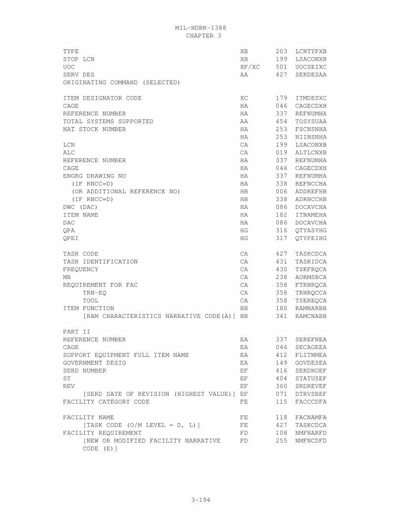
CHAPTER 3MIL-HDBK-1388
3-194
TYPE XB 203 LCNTYPXB STOP LCN XB 199 LSACONXB UOC XF/XC 501 UOCSEIXC SERV DES AA 427 SERDESAA ORIGINATING COMMAND (SELECTED)
ITEM DESIGNATOR CODE XC 179 ITMDESXC CAGE HA 046 CAGECDXH REFERENCE NUMBER HA 337 REFNUMHA TOTAL SYSTEMS SUPPORTED AA 454 TOSYSUAA NAT STOCK NUMBER HA 253 FSCNSNHA HA 253 NIINSNHA LCN CA 199 LSACONXB ALC CA 019 ALTLCNXB REFERENCE NUMBER HA 337 REFNUMHA CAGE HA 046 CAGECDXH ENGRG DRAWING NO HA 337 REFNUMHA (IF RNCC=D) HA 338 REFNCCHA (OR ADDITIONAL REFERENCE NO) HB 006 ADDREFHB (IF RNCC=D) HB 338 ADRNCCHB DWC (DAC) HA 086 DOCAVCHA ITEM NAME HA 182 ITNAMEHA DAC HA 086 DOCAVCHA QPA HG 316 QTYASYHG QPEI HG 317 QTYPEIHG
TASK CODE CA 427 TASKCDCA TASK IDENTIFICATION CA 431 TASKIDCA FREQUENCY CA 430 TSKFRQCA MB CA 238 AORMSBCA REQUIREMENT FOR FAC CA 358 FTRNRQCA TRN-EQ CA 358 TRNRQCCA TOOL CA 358 TSEREQCA ITEM FUNCTION BB 180 RAMNARBB [RAM CHARACTERISTICS NARRATIVE CODE(A)] BB 341 RAMCNABB
PART II REFERENCE NUMBER EA 337 SEREFNEA CAGE EA 046 SECAGEEA SUPPORT EQUIPMENT FULL ITEM NAME EA 412 FLITNMEA GOVERNMENT DESIG EA 149 GOVDESEA SERD NUMBER EF 416 SERDNOEF ST EF 404 STATUSEF REV EF 360 SRDREVEF [SERD DATE OF REVISION (HIGHEST VALUE)] EF 071 DTRVSBEF FACILITY CATEGORY CODE FE 115 FACCCDFA
FACILITY NAME FE 118 FACNAMFA [TASK CODE (O/M LEVEL = D, L)] FE 427 TASKCDCA FACILITY REQUIREMENT FD 108 NMFNARFD [NEW OR MODIFIED FACILITY NARRATIVE FD 255 NMFNCDFD CODE (E)]

CHAPTER 3MIL-HDBK-1388
3-195
PART III CFE GFE EA 056 CFEGFEEA YEAR FIELD EA 518 YRFLDGEA TOTAL QUANTITY AUTHORIZED ED 399 SEQTYAED NONRECURRING COST DEVELOPMENT EA 153 HDWRPREA DESIGN EA 080 DSNPRCEA PASS-THRU EA 285 PASTHREA ILS EA 170 ILSPRCEA RECURRING EA 332 RCURCSEA CONDITION CA 428 TCONDACA CA 428 TCONDBCA CA 428 TCONDCCA MAN-HOURS CA 225 MSDMMHCA CA 225 PRDMMHCA ELAPSED TIME CA 224 MSDMETCA CA 224 PRDMETCA PERSON ID CD 288 SUBPIDCD SKILL SPEC CODE CD 387 SKSPCDGA SKILL LEVEL CODE GA 386 SKLVCDGA MAN-MINUTES (CALCULATED) CD 226 SUBMMMCD

CHAPTER 3MIL-HDBK-1388
3-196
LSA-077

CHAPTER 3MIL-HDBK-1388
3-197

CHAPTER 3MIL-HDBK-1388
3-198

CHAPTER 3MIL-HDBK-1388
3-199
30.44 LSA-078 HAZARDOUS MATERIAL SUMMARY REPORT SPECIFICATION
30.44.1 SELECTION. The LSA-078 summary is selected by mandatory LCN and TYPE,and optional SERV DES, ALC, STOP LCN, and UOC.
30.44.2 PROCESSING. In order to qualify for LSA-078 summary, an LCN/task codemust be contained within the selected LCN range/Serv Des Selection. Provisioned items for qualified LCN/Tasks (table CI) are further qualified by having entries in either Hazardous Storage, Waste Storage or Disposal Costs.COMPUTED QUANTITY is calculated by multiplying the TASK FREQ times theQTY/TASK. TOTAL QUANTITY REQUIRED is calculated by summing all COMPUTEDQUANTITY for a given Reference Number and CAGE.
30.44.3 REPORT FORMAT. See Figure 3.41
30.44.4 REPORT SEQUENCE. The LSA-078 summary is sequenced by ascending CAGEand Reference Number. Within each Reference Number, tasks are sorted inascending LCN/ALC and Task Code.
30.44.5 DATA SOURCE. The source of data appearing on the LSA-078 summary isdepicted below by data table and element codes.
Report header Table Code DED Element Code EIAC HG 096 EIACODXA ITEM NAME HA 182 ITNAMEHA START LCN HG 199 LSACONXB ALC HG 019 ALTLCNXB TYPE HG 203 LCNTYPXB STOP LCN HG 199 LSACONXB UOC HO/XC 501 UOCSEIXC SERVIC DES CA 427 TASKCDCA CAGE HG 046 CAGECDXH REFERENCE NUMBER HG 337 REFNUMHA ITEM NAME HA 182 ITNAMEHA MATERIALS STORAGE COST HA 156 HMSCOSHA WASTE STORAGE COST HA 158 HWSCOSHA WASTE DISPOSAL COST HA 157 HWDCOSHA UM HA 491 UNITMSHA UM PRICE HE 492 UMPRICHE [PROVISIONING UM PRICE] HE 314 PROUMPHE LCN CI 199 TSKLCNCI ALC CI 019 TSKALCCI TASK CODE CI 427 TSKTCDCI TASK IDENTIFICATION CA 431 TASKIDCA TASK FREQ CA 430 TSKFRQCA MB CA 238 AORMSBCA COMPUTED QUANTITY (COMPUTED) QTY/TASK CI 319 PQTYTKCI TOTAL QTY RECOMMENDED HG 453 TOTQTYHG [LCN] CI 199 PROLCNCI [ALC] CI 019 PROALCCI [CAGE] CI 046 PROCAGCI [REFERENCE NUMBER] CI 337 PROREFCI TOTAL QUANTITY REQUIRED (COMPUTED)

CHAPTER 3MIL-HDBK-1388
3-200
LSA-078
CHAPTER 3MIL-HDBK-1388
3-201
30.45 LSA-080 BILL OF MATERIALS REPORT SPECIFICATION
30.45.1 SELECTION. The LSA-080 summary is selected based on the Sequenceoption by either (LCN sequence) mandatory EIAC, LCN, and UOC, or (PLISNsequence) PCCN and UOC; and optional ALC (default is all ALCs), STOP LCN(default is all LCNS subordinate to, and including, the start LCN), andLCN-CODE. PLISN Sequence takes precedence over LCN sequence.
a. If the report is selected by LCN, then the LCN-CODE should specify ifthe type of LCNs are either: Classical or Modified Classical.
30.45.2 PROCESSING. In order to produce an LSA-080 summary at least onequalified row of information must be within the specified PCCN or LCN range.
a. The LSA-080 report, Part I, identifies parts to the assemblies ofwhich they are contained, in order that the parts documentation in the datatables can be checked for completeness against the assembly drawings. Eachassembly will only show parts one indenture lower;, e.g., a "C" indenturedassembly will only show "D" indentured items. These items may be both repairparts and spares. If the item is a spare, a separate page breakdown of theitem will appear on the report.
b. If the report is selected by LCN, then either the LCN structure, orLCN-Indenture Code and the LCN "values" are used to place items to assemblies.All items sorted in ascending LCN sequence with either an LCN-IC or structurevalue of one indenture greater are placed as items to an assembly, untilwithin the sorted range another item is found at the same indenture level, orgreater than the assembly. Items at more than one indenture greater are"grouped" with the item (now assembly) immediately preceding this indenturechange. ALC items are "grouped" together as an assembly/item set, if there isno indenture level missing between them. If an ALC item does not have amatching ALC it is then "grouped" to the blank, or basic assembly item.
c. If PCCN is selected, then PLISN and IC are used to sort items toassemblies, with all items sorted in ascending PLISN sequence of one ICgreater than the IC of the assembly PLISN record placed below the assemblyPLISN until an IC is encountered that is equal to or greater than the assemblyIC. The NHA PLISN is a value found in table HH which is one indenture lessthan the item with a value closest to the item’s PLISN value and without anNHA-Indicator of "*".
b. The part II is produced automatically when the LSA-080 report isrequested and data errors are found. The report identifies the items havingerroneous data, and provides a message describing the type of error found.The errors that the edit routine will detect are:
(1) Error Code 1. If an item is SMR coded: with "Z", or "B" in thefourth position, but parts are contained below this item with source codesother than K- or XA, then this error is output. (appears on part I withasterisks by both the assembly and/or part location.
(2) Error Code 2. An item does not have an identifiable next higherassembly, e.g., if the indenture structure lists the item as an "F" and thelogical NHA by file sort is a "D". then this error is output (part II only).

CHAPTER 3MIL-HDBK-1388
3-202
(3) Error Code 3. No indenture Code. This item appears on part IIonly, when the selection is made by PCCN. If the selection is by LCN, thenthe item is shown on both parts I and II.
(4) Error Code 4. An item whose Source, Maintenance andRecoverability (SMR) code is blank or incomplete (without 3/4th positions).
(5) Error Code 5. If LCN-Code is "CLASSICAL" and duplicate LCNs areencountered, each duplicate receives this error message. The item(s) willappear on both parts I and II.
(6) Error Code 6. Allowable recoverability codes are as followsbased on the repair code:
If position 4 is: the position 5 must be: Z Z, A O (2, 3, 4, 5, 6) Navy only O, F, H, G, D, L, A F F, H, G, D, L, A H H, G, D, L, A G G, D, L, A D D, L, A L D, L, A B Z, A
(7) An assembly is SMR coded repairable (e.g., SMR-4 is not Z or B)but has no parts breakout beneath it.
c. Items having the errors codes 2 and 3 with PCCN selection are listedon the LSA-080 part II only. Other errors will be flagged with "**" to theright of the line the error appears in part I and also displayed in part II.The error messages will be displayed on part II.
30.45.3 REPORT FORMAT. See Figure 3.42
30.45.4 REPORT SEQUENCE. The report is sequenced in either ascending assemblyREFERENCE NUMBER and CAGE (ASCII sequence) or in ascending assembly PLISN(EBCDIC sequence) based on the selection option specified in SEQ OPTION.
30.45.5 DATA SOURCE. The source of data appearing on the LSA-080 summary isdepicted below by data table and element codes.
Report header Table Code DED Element Code
EIAC HG 096 EIACODXA ITEM NAME HA 182 ITNAMEHA START LCN HG 199 LSACONXB ALC HG 019 ALTLCNXB TYPE HG 203 LCNTYPXB STOP LCN HG 199 LSACONXB UOC XC 501 UOCSEIXCUOC is matched VIA the HO Table SEQ OPT (SELECTED) LCN STRUCTURE XA 202 LCNSTRXA
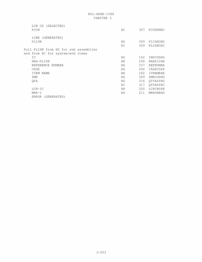
CHAPTER 3MIL-HDBK-1388
3-203
LCN CD (SELECTED) PCCN XC 307 PCCNUMXC
LINE (GENERATED) PLISN HG 309 PLISNOHG XC 309 PLISNOXCPull PLISN from HG for sub assembliesand from XC for system/end items IC HG 162 INDCODHG NHA-PLISN HH 258 NHAPLIHH REFERENCE NUMBER HG 337 REFNUMHA CAGE HG 046 CAGECDXH ITEM NAME HA 182 ITNAMEHA SMR HG 389 SMRCODHG QPA HG 316 QTYASYHG XC 317 QTYASYXC LCN-IC XB 200 LCNINDXB MRR-I HG 211 MRRONEHG ERROR (GENERATED)

CHAPTER 3MIL-HDBK-1388
3-204
LSA-080

CHAPTER 3MIL-HDBK-1388
3-205
30.46 LSA-085 TRANSPORTABILITY SUMMARY REPORT SPECIFICATION
30.46.1 SELECTION. The LSA-085 summary is selectable by mandatory EIAC, StartLCN, LCN TYPE, and UOC; and optional ALC (default is all ALCs) and Stop LCN(default is all LCNs subordinate to, and including, the start LCNs). Thereport has no optional selections.
30.46.2 PROCESSING. The report will pull information from the JA, JB, JC, JD,JE, JF, HA, HG, AND XH TABLES against the specific LCN range. If Type is (F)then NSN and Related Data, CAGE, and Reference Number may not be able tobe pulled from there respective tables. The Reference Number is wrapped at16 positions.
30.46.3 REPORT FORMAT. See Figure 3.43
30.46.4 REPORT SEQUENCE. The report is sequenced by ascending value of the LCN.
30.46.5 DATA SOURCES. The source of the data appearing on the LSA-085 summaryis depicted below by data table and element codes.
Report Header Table Code DED Element Code EIAC XB 096 EIACODXA LCN NOMENCLATURE XB 201 LCNAMEXB START LCN XB 199 LSACONXB ALC XB 019 ALTLCNXB TYPE XB 203 LCNTYPXB STOP LCN XB 199 LSACONXB UOC XF/XC 501 UOCSEIXC REFERENCE NUMBER HG 337 REFNUMHA CAGE HG 046 CAGECDXH NATIONAL STOCK NUMBER NSN COGNIZANCE CODE HA 253 COGNSNHA NSN MATERIEL CONTROL CODE HA 253 MATNSNHA NSN FEDERAL SUPPLY CLASSIFICATION HA 253 FSCNSNHA NSN NATIONAL ITEM IDENTIFICATION NUMBER HA 253 NIINSNHA NSN SPECIAL MATERIAL IDENTIFICATION CODE/ HA 253 SMMNSNHA MATERIEL MANAGEMENT AGGREGATION CODE NSN ACTIVITY CODE HA 253 ACTNSNHA CONTRACT NUMBER JA 055 CONNUMJA REVISION DATE JA 071 TRCHRDJA TYPE ACQ XA 478 WSTYAQXA THEATER OF OPER JA 451 TRCHTHJA CONTRACTOR NAME AND LOCATION (HEADER) NAME XH 047 CANAMEXH STREET XH 047 CASTREXH CITY XH 047 CACITYXH STATE XH 047 CASTATXH NATION XH 047 CANATNXH POSTAL ZONE XH 047 CAPOZOXH PROCUREMENT SCHEDULE (HEADER) FY JE 145 TRAFYRJE 1QTY JE 298 FIQPQTJE 2QTY JE 298 SQPQTYJE 3QTY JE 298 TQPQTYJE

CHAPTER 3MIL-HDBK-1388
3-206
4QTY JE 298 FQPQTYJE MILITARY UNIT TYPE JA 242 MILUNTJA PROPER SHIPPING NAME JA 304 PROPSNJA NOFF JA 260 NOPRFFJA NET EXP WEIGHT JA 254 NETEXWJA SPEED JA 400 SPSPEDJA TOWING SPEED JA 455 TWSPEDJA SECT ID JA 366 SECTIDJA --SHIPPING MODES-- FREIGHT CLASSIFICATION JB 146 FRCLASJB SHIPPING CONFIGURATION JB 380 SHPCONJB CONTAINER LENGTH JB 053 CONLENJB CONTAINER TYPE JB 054 CONTYPJB RAIL USE JB 326 RAILUSJB RAIL TRANSPORTATION COUNTRY OR COUNTRIES JB 325 RAILTCJB HIGHWAY PRIME MODEL (HEADER) LOAD JB 250 HIPRMLJB TYPE JB 251 HIPRMTJB HIGHWAY ALTERNATE MODEL LOAD JB 250 HALTMLJB TYPE JB 251 HALTMTJB SHIP ITEM DESIGNATOR JB 469 TRITDRJB (TRANSPORTATION CHARACTER MODE TYPE (F)) JB 464 TRCHMTJB DECK STOWAGE JB 072 SDECKSJB LIGHTERAGE ITEM DESIGNATOR JB 469 TRITDRJB (TRANSPORTATION CHARACTER MODE TYPE (D)) JB 464 TRCHMTJB DECK STOWAGE JB 072 SDECKSJB AIRCRAFT ITEM DESIGNATOR JB 469 TRITDRJB (TRANSPORTATION CHARACTER MODE TYPE (A)) JB 464 TRCHMTJB EXTERNAL OR INTERNAL LOAD INDICATOR JB 104 EOILINJB HELICOPTER ITEM DESIGNATOR JB 469 TRITDRJB (TRANSPORTATION CHARACTER MODE TYPE (B)) JB 464 TRCHMTJB EXTERNAL OR INTERNAL LOAD INDICATOR JB 104 EOILINJB HELICOPTER MISSION REQUIREMENTS (HEADER) ALTITUDE JB 159 HMATLRJB DISTANCE JB 159 HMDISRJB PAYLOAD JB 159 HMPAYRJB TEMPERATURE JB 159 HMTMPRJB TIME JB 159 HMTIMRJB --TRANSPORTED END ITEM-- SHIPPING WEIGHT EMPTY JC 381 SHWEEMJC SHIPPING WEIGHT LOADED JC 381 SHWELDJC OPERATIONAL WEIGHT EMPTY JC 276 OPWEEMJC MIL LOAD CLASS EMP JC 241 HICLNEJC OPERATIONAL WEIGHT LOADED JC 276 OPWELDJC MIL LOAD CLASS LOADED JC 241 HICLNLJC CREST ANGLE JC 063 CREANGJC AXLE LENGTH (HEADER) FRONT IN JC 029 TWALFIJC FRONT OUT JC 029 TWALFOJC REAR IN JC 029 TWALRIJC REAR OUT JC 029 TWALROJC MOBILITY TYPE JC 249 MOBTYPJC TRANSPORTED CONFIGURATION NUMBER JC 473 TRCONMJC

CHAPTER 3MIL-HDBK-1388
3-207
TRACKED GROUND PRESSURE JC 456 TRGRPRJC TRACKED PADS TOUCHING JC 458 TRNUPTJC TRACKED ROAD WHEEL WEIGHT JC 459 TRRWWTJC TRACKED PAD SHOE AREA JC 457 TRPSARJC UM JC 491 TPSAUMJC NUMBER OF SKIDS JC 264 SNUMSKJC SKID AREA JC 384 SDSICGJC UM JC 491 SKADUMJC MOBILITY TYPE JC 249 MOBTYPJC TRANSPORTED CONFIGURATION NUMBER JC 473 TRCONMJC WHEELED INFLATION PRESSURE JC 507 WHINPRJC WHEELED NUMBER OF PLIES JC 508 WHNUPLJC WHEELED NUMBER TIRES JC 509 WHNUTIJC WHEELED TIRE LOAD RATINGS JC 510 WHTLDRJC WHEELED TIRE SIZE JC 512 WHTIFTJC WHEELED WEIGHT RATINGS JC 513 WHWERAJC MOBILITY TYPE JC 249 MOBTYPJC TRANSPORTED CONFIGURATION NUMBER JC 473 TRCONMJC WHEELED TIRE REQUIREMENTS JD 511 WHTRLOJD TRANSPORTED END ITEM NARRATIVE CODE OF (A) JD 474 TREINCJD SKID REMARKS JD 385 WHTRLOJD TRANSPORTED END ITEM NARRATIVE CODE OF (B) JD 474 TREINCJD TURNING INFORMATION JD 477 WHTRLOJD TRANSPORTED END ITEM NARRATIVE CODE OF (C) JD 474 TREINCJD WHEELED AXLE AND SUSPENSION REMARKS JD 506 WHTRLOJD TRANSPORTED END ITEM NARRATIVE CODE OF (D) JD 474 TREINCJD TRANSPORTED OTHER EQUIPMENT JD 475 WHTRLOJD TRANSPORTED END ITEM NARRATIVE CODE OF (E) JD 474 TREINCJD TRANSPORTATION SHOCK VIBRATION REMARKS JF 382 TRANARJF (TRANSPORTATION NARRATIVE CODE OF (A)) JF 475 TRANCDJF LIFTING AND TIEDOWN REMARKS JF 192 TRANARJF (TRANSPORTATION NARRATIVE CODE OF (B)) JF 474 TRANCDJF TRANSPORTATION PROJECTION REMARKS JF 471 TRANARJF (TRANSPORTATION NARRATIVE CODE OF (C)) JF 474 TRANCDJF REGULATORY REQUIREMENTS JF 340 TRANARJF (TRANSPORTATION NARRATIVE CODE OF (D)) JF 474 TRANCDJF TRANSPORTATION REMARKS JF 472 TRANARJF (TRANSPORTATION NARRATIVE CODE OF (E)) JF 474 TRANCDJF SPECIAL SERVICE AND EQUIPMENT JF 398 TRANARJF (TRANSPORTATION NARRATIVE CODE OF (F)) JF 474 TRANCDJF SECTIONALIZED REMARKS JF 368 TRANARJF (TRANSPORTATION NARRATIVE CODE OF (G)) JF 474 TRANCDJF TRANSPORTED TO AND FROM JF 476 TRANARJF (TRANSPORTATION NARRATIVE CODE OF (H)) JF 474 TRANCDJF ENVIRONMENTAL CONSIDERATIONS JF 099 TRANARJF (TRANSPORTATION NARRATIVE CODE OF (I)) JF 474 TRANCDJF MILITARY DISTANCE CLASSIFICATION JF 240 TRANARJF (TRANSPORTATION NARRATIVE CODE OF (J)) JF 474 TRANCDJF UNUSUAL AND SPECIAL REQUIREMENTS JF 500 TRANARJF (TRANSPORTATION NARRATIVE CODE OF (K)) JF 474 TRANCDJF VENTING AND PROTECTIVE CLOTHING JF 504 TRANARJF (TRANSPORTATION NARRATIVE CODE OF (L)) JF 474 TRANCDJF DISASTER RESPONSE FORCE REQUIREMENTS JF 082 TRANARJF (TRANSPORTATION NARRATIVE CODE OF (M)) JF 474 TRANCDJF

CHAPTER 3MIL-HDBK-1388
3-208
LSA-085

CHAPTER 3MIL-HDBK-1388
3-209

CHAPTER 3MIL-HDBK-1388
3-210

CHAPTER 3MIL-HDBK-1388
3-211
30.47 LSA-126 LCN/PCCN INDENTURE STRUCTURE TREE REPORT SPECIFICATION
30.47.1 SELECTION. The LSA-126 summary is selected by either (LCN sequence)mandatory EIAC, LCN or (PLISN sequence) PCCN; and optional ALC (default is allALCs), STOP LCN (default is all LCNS subordinate to, and including, the startLCN) and UOC (default is all UOCs). PLISN Sequence takes precedence over LCNsequence.
30.47.2 PROCESSING. In order to produce an LSA-126 summary at least one rowof HG information must be contained within the selected LCN/PCCN range.
a. If the report is selected by LCN then items are sequenced for thereport by ascending LCN. Identical ALCs (other than 00) are sorted and"grouped" based on no break in the indenture structure of the items. If abreak in structure occurs, then these items are sorted back to the basic or"blank" ALC. Items are placed in the report indenture breakdown by the LCN-IC(XB).
b. If the report is selected by PCCN, then items are sequenced byascending PLISN and placed in indenture breakdown by the ProvisioningIndenture Code (HG/XC)
30.47.3 REPORT FORMAT. See Figure 3.44
30.47.4 REPORT SEQUENCE. Report is sequenced by ascending LCN/ALC for LCNrange selection; and by PLISN for PCCN selection.
30.47.5 DATA SOURCE. The source of data appearing on the LSA-126 summary isdepicted below by data table and element codes.
Report header Table Code DED Element Code EIAC HG 096 EIACODXA ITEM NAME HA 182 ITNAMEHA START LCN HG 199 LSACONXB ALC HG 019 ALTLCNXB TYPE HG 203 LCNTYPXB STOP LCN HG 199 LSACONXB UOC XC 501 UOCSEIXCUOC is match VIA the HO table LCN STRUCTURE XA 202 LCNSTRXA LCN CD (SELECTED) PCCN HG 307 PCCNUMHG
ITEM NAME HA 182 ITNAMEHA NSN HA 253 FSCNSNHA HA 253 NIINSNHA SMR HG 389 SMRCODHG LCN-IC XB 200 LCNINDXB PLISN HG 309 PLISNOHG XC 309 PLISNOXC CAL-IC (GENERATED) REFERENCE NUMBER HG 337 REFNUMHA CAGE HG 046 CAGECDXH IC HG 162 INDCODHG

CHAPTER 3MIL-HDBK-1388
3-212
LSA-126
CHAPTER 3MIL-HDBK-1388
3-213
30.48 LSA-151 PROVISIONING PARTS LIST INDEX REPORT SPECIFICATION
30.48.1 SELECTION. The LSA-151 summary is selected by mandatory LCN, andoptional ALC, STOP LCN, UOC, SEQ, PCCN and PTD-SEL
30.48.2 PROCESSING. In order to produce an LSA-151 summary at least one rowof information must be contained within the selected LCN range/PCCN. Whenselected by LCN, this report may be across multiple PCCNs. The report can begenerated in reference number, LCN, or PLISN sequence. Additional data whichfurther describes the item at its usage level(s) are provided for the user’sinformation (i.e., item name, quantities, SMR, etc.).
a. Next Higher Assembly Reference Number and CAGE is determined by theitem’s NHA PLISN with an "N" NHA Indicator, and one indenture less than theitem. The HG Item’s keys are compared to HH keys to find the NHA PLISN. Asearch for this PLISN is conducted in the HG table to find the NHA. Both thePLISN and NHA PLISN must have the same t PCCN (found in XC table through HO).The HG table key Reference Number and CAGE containing the PLISN matched to theNHA PLISN is the NHA reference number and CAGE.
30.48.3 REPORT FORMAT. See Figure 3.45
30.48.4. REPORT SEQUENCE. The report is sequenced by either ascending PLISN orReference Number based on the SEQ selected.
30.48.5 DATA SOURCE. The source of data appearing on the LSA-151 summary isdepicted below by data table and element codes.
Report header Table Code DED Element Code
EIAC HG 096 EIACODXA ITEM NAME HA 182 ITNAMEHA START LCN HG 199 LSACONXB ALC HG 019 ALTLCNXB TYPE HG 203 LCNTYPXB STOP LCN HG 199 LSACONXB UOC HO/XC 501 UOCSEIXC PCCN XC 307 PCCNUMXC SEQ (SELECTED) PTD-SEL PPL HG 313 PPLPTDHG SFPPL HG 313 SFPPTDHG LLTIL HG 313 LLIPTDHG RIL HG 313 RILPTDHG ISIL HG 313 ISLPTDHG TTEL HG 313 TTLPTDHG CBIL HG 313 CBLPTDHG PCL HG 313 PCLPTDHG SCPL HG 313 SCPPTDHG ARA HG 313 ARAPTDHG ARB HG 313 ARBPTDHG
CAGE HG 046 CAGECDXH REFERENCE NUMBER HG 337 REFNUMHA

CHAPTER 3MIL-HDBK-1388
3-214
PCCN XC 307 PCCNUMXC PLISN HG 309 PLISNOHG XC 309 PLISNOXC TOC HG 481 TOCCODHG XC 481 TOCCODXC LCN HG 199 LSACONXB ALC HG 019 ALTLCNXB IC HG 162 INDCODHG ITEM NAME HA 182 ITNAMEHA QPA HG 316 QTYASYHG XC 316 QTYASYXC QPEI HG 317 QTYPEIHG XC 317 QTYPEIXC UM HA 491 UNITMSHA SMR HG 389 SMRCODHG EC HG 100 ESSCODHG PLT HA 299 PRDLDTHA NEXT HIGHER ASSEMBLY CAGE HG 046 CAGECDXH REFERENCE NUMBER HG 337 REFNUMHA [NHA PLISN] HH 258 NHAPLIHH

CHAPTER 3MIL-HDBK-1388
3-215
LSA-151
CHAPTER 3MIL-HDBK-1388
3-216
30.49 LSA-152 PLISN ASSIGNMENT/REASSIGNMENT REPORT SPECIFICATION
30.49.1 SELECTION. The LSA-152 summary is selectable by mandatory EIAC, andeither Start LCN or PCCN. There is a wide range of options when using thePLISN assignment routine:
a. NHA PLISNs and/or ICs may be assigned to the PMF, if this option isselected on the 152 report. (1) If the file is constructed using the classical/modifiedclassical LCN assignment technique, the IC may be assigned, provided the LCNstructure exists in the XA table or the indenture code in the XB table. Asterisk ICs may be assigned to the parts file based on the ICC of "9"representing kit components being previously assigned (Table HG). An option isalso available to assign a constant NHA PLISN indicator of "N" against each NHAPLISN assigned to the HH table. (2) When a sequential LCN assignment method is utilized, the LCNstructure field is left blank in the XA table, and the LCN-ICs must beentered on the XB table in order to assign NHA PLISN. The IC (Table HG)should be that of the provisioned end item, while the LCN-IC should be relatedto the system level in the LSAR. b. When assigning PLISNs for a subordinate end item the IC is notassigned to the HG table. For example, a separately provisioned end item atthe "C" indenture to the system (LCN-IC,Table XB) will have an IC of "A" comeout on the LSA-152, and LSA-036 reports but will keep its IC of "C" assignedunder the system end item assignment. All components to the subordinate enditem will then have their IC assigned as before. For example, a "D" indentureitem under the "C" indenture subordinate end item will have a "B" IC assignedwhen PLISN assignment is run on the "C" indenture subordinate end item. c. PLISNs may be assigned only to items that qualify by PTD SelectionCode for a specified Provisioning List (PL) or lists (Table HG). d. PLISNs may be assigned in either topdown (LCN) or Reference Numbersequence. When PLISNs are assigned in Reference Number sequence, the systemwill lock out the option to assign NHA PLISNs/ICs. Default is topdown. e. PLISNs may be assigned as either all alphabetic, alphanumeric,numeric, or, first position alphabetic, then second through fourth positionnumeric. Default is alphanumeric. f. A starting PLISN value may be specified on the report selection card. g. PLISN values of "AAAA" through "AAAHZ" may be reserved for the systemlevel and separately provisioned end items (Model Reserve). If this option isselected, a starting model PLISN value may be specified (within the givenrange). If none is selected, the first model PLISN assignment will be "AAAA". h. PLISNs may be assigned to overlay old PLISN values established in thefile; to overlay PLISNs and to move the old PLISN value to the Prior ItemPLISN field; or to assign PLISNs only to items that do not have a PLISN valuealready established (insert) (Insert/Overlay selection on report). If theinsert option is chosen, PLISNs already assigned to the file must match withthe LCN structure or LCN-ICs of the selected LCN range. The Prior Item PLISNmay be added as a separate selection from the I/O selection as shown inAppendix B of -2B. i. It is possible to skip PLISN values between the assigned PLISNs forfuture use, when the item is impacted by Design Change Notice or EngineeringChange Proposals, or for when the item having PLISNs assigned is not fullybroken down to piece part level. This option cannot be utilized if the insertoption (paragraph h) is in use. PLISN gaps may be as great as 1,121.

CHAPTER 3MIL-HDBK-1388
3-217
j. PLISNs may be assigned to items based upon the Data Status Code (TableHG) contained against the qualified item. This can be useful when performingincremental provisioning on an LSAR that is not fully mature. k. LCN structure and System 036 are no longer selection options.
30.49.2 PROCESSING. This summary provides a listing, by reference number, ofPLISN, Indenture Code (IC), NHA PLISN, and PRIOR ITEM PLISN, assigned by theLSAR system based on parameters of the assignment select card. The summarywill depict the file content before and after the assignments or reassignmentsare made (PLISNs are assigned using the EBCDIC collating sequence). As anoption, this report can be used to assign provisioning related control andreference data to the LSAR Parts Master File. The format is contained onfigure 60. Spacing between rows and columns is not critical on this report. a. It is necessary that the LSAR be properly structured using either auniform (nonbroken) LCN structure when applying either a classical or modifiedclassical LCN assignment technique; or an LCN-IC (Table XB) assignment withoutmissing or unlinked indenture levels, when LCNs are assigned using thesequential method. Using the LSA-080 report, the analyst can review the filefor correct structure, or by using the LSA-152 report detect error conditionsin file structure. b. The LSA-152 report consists of two parts. Part I will only be outputwhen an error in file structure is encountered, or when the PLISN assignment(with selected PLISN spacing) exceeds the limit of 9999 for the proposedassigned PMF candidates. When these occur, the error location in the file isdepicted on the report with a display of the unlinked or remaining filesegment. If an error condition does occur, the LSA-152 process will notassign any PLISNs, but will continue processing to determine whetheradditional error conditions exist in the file. Validated LSAR systems will berequired to have the capability to produce an error listing for the LSA-152report. However, the format, messages and explanation of those messages forthe error listing is vendor dependent. Part II of the report reflects theresults of the PLISN assignment/reassignment; only a Part I or a Part II willbe produced in a processing cycle. Also, PLISN assignment must occur as anexclusive cycle. c. The report selection for PLISN assignment occurs within a PCCN andoptionally Start and Stop LCN range. ALC is not a selection option.Alternate LCNs must be considered when assigning the basic LCN PLISNs becausealternates may have basic items as NHAs. A row in table HO creates the enditem (XC) to part application (HG) relationship. One HG row cannot be relatedto multiple PCCNs except when the item is a subordinate end item. When theitem is a subordinate end item, HO would have one row depicting the end itemrelationship (end item and item LCN-ALCs are the same), and one or more rowsshowing the relationship to the system. Having the end items located in theXC table, and the fact that no other item except a subordinate end item can belinked to more than one PCCN, makes the suppression indicator code obsolete. d. Since there are unlimited "correct" structuring techniques using theALC, there is no system edit to detect errors in file structure when the ALCis utilized, other than missing an indenture level when the ALC is beingsequenced to the "basic" LCN structure. ALC assignment errors, therefore, canonly be detected by a manual review of the LSA-152 or LSA-080 reports.
30.49.3 REPORT FORMAT. See Figure 3.46
30.49.4 REPORT SEQUENCE. Part II of this summary is sequenced by ascending
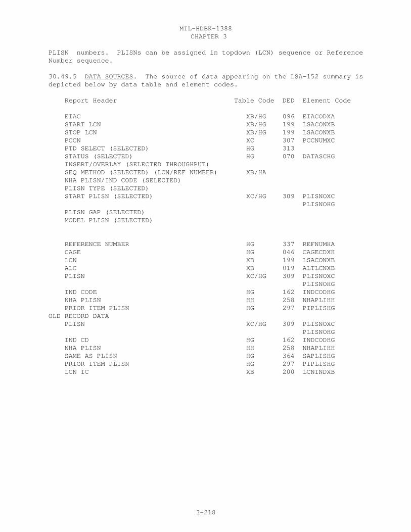
CHAPTER 3MIL-HDBK-1388
3-218
PLISN numbers. PLISNs can be assigned in topdown (LCN) sequence or ReferenceNumber sequence.
30.49.5 DATA SOURCES. The source of data appearing on the LSA-152 summary isdepicted below by data table and element codes.
Report Header Table Code DED Element Code
EIAC XB/HG 096 EIACODXA START LCN XB/HG 199 LSACONXB STOP LCN XB/HG 199 LSACONXB PCCN XC 307 PCCNUMXC PTD SELECT (SELECTED) HG 313 STATUS (SELECTED) HG 070 DATASCHG INSERT/OVERLAY (SELECTED THROUGHPUT) SEQ METHOD (SELECTED) (LCN/REF NUMBER) XB/HA NHA PLISN/IND CODE (SELECTED) PLISN TYPE (SELECTED) START PLISN (SELECTED) XC/HG 309 PLISNOXC PLISNOHG PLISN GAP (SELECTED) MODEL PLISN (SELECTED)
REFERENCE NUMBER HG 337 REFNUMHA CAGE HG 046 CAGECDXH LCN XB 199 LSACONXB ALC XB 019 ALTLCNXB PLISN XC/HG 309 PLISNOXC PLISNOHG IND CODE HG 162 INDCODHG NHA PLISN HH 258 NHAPLIHH PRIOR ITEM PLISN HG 297 PIPLISHGOLD RECORD DATA PLISN XC/HG 309 PLISNOXC PLISNOHG IND CD HG 162 INDCODHG NHA PLISN HH 258 NHAPLIHH SAME AS PLISN HG 364 SAPLISHG PRIOR ITEM PLISN HG 297 PIPLISHG LCN IC XB 200 LCNINDXB

CHAPTER 3MIL-HDBK-1388
3-219
LSA-152

CHAPTER 3MIL-HDBK-1388
3-220
30.50 LSA-154 PROVISIONING PARTS BREAKOUT SUMMARY REPORT SPECIFICATION
30.50.1 SELECTION. The LSA-154 summary is selected by either a mandatory LCNor REFERENCE NUMBER and CAGE, and optional ALC, STOP LCN, UOC, CTIC1, CTIC2,SRC, and PART.
30.50.2 PROCESSING. In order to produce an LSA-154 summary at least one rowof information (table HG) qualified by specified CTICs or Source Codes (SRC)must be contained within the selected LCN range. If the selection is made byReference Number/CAGE, then this number must be contained in table HA.
a. The report is selectable by Part I only or by both parts.
b. If both parts of the report are selected, a page break will occurbetween each change in Reference Number/CAGE. If only part I is selected,multiple Reference Number/CAGEs may appear on the same page.
c. Next Higher Assembly Reference Number and CAGE is determined by theitem’s NHA PLISN with an "N" NHA Indicator, and one indenture less than theitem. The HG Item’s keys are compared to HH keys to find the NHA PLISN. Asearch for this PLISN is conducted in the HG table to find the NHA. Both thePLISN and NHA PLISN must have the same t PCCN (found in XC table through HO).The HG table key Reference Number and CAGE containing the PLISN matched to theNHA PLISN is the NHA reference number and CAGE. (Same process for LSA-151summary).
30.50.3 REPORT FORMAT. See Figure 3.47
30.50.4 REPORT SEQUENCE. The report is sequenced in ascending ReferenceNumber and CAGE.
30.50.5 DATA SOURCE. The source of data appearing on the LSA-154 summary isdepicted below by data table and element codes.
Report header Table Code DED Element Code
EIAC HG 096 EIACODXA ITEM NAME HA 182 ITNAMEHA START LCN HG 199 LSACONXB ALC HG 019 ALTLCNXB TYPE HG 203 LCNTYPXB STOP LCN HG 199 LSACONXB CTIC1 HA 058 CTICODHA CTIC2 HA 058 CTICODHA SOURCE HG 389 SMRCODHG CAGE HG 046 CAGECDXH REFERENCE NUMBER HG 337 REFNUMHA PARTS (SELECTED)
REFERENCE NUMBER HG 337 REFNUMHA CAGE HG 046 CAGECDXH RNCC HA 338 REFNCCHA RNVC HA 339 REFNVCHA DAC HA 086 DOCAVCHA

CHAPTER 3MIL-HDBK-1388
3-221
ITEM NAME HA 182 ITNAMEHA CTIC HA 058 CTICODHA PLT HA 299 PRDLDTHA AMC HA 003 ACQMETHA AMSC HA 004 AMSUFCHA UM HA 491 UNITMSHA
ADDITIONAL REFERENCE NUMBER(S) HB 006 ADDREFHB CAGE HB 046 ADCAGEHB RNCC HB 338 ADRNCCHB RNVC HB 339 ADRNVCHB CTIC CAGE HC 046 CTCAGEHC CAGE NAME XH 047 CANAMEXH UM PRICE HE 492 UMPRICHE LOT QUANTITY FROM HE 205 LOTQFMHE TO HE 205 LOTQTOHE CPC HE 051 CURPRCHE TUC HE 485 TUMPRCHE FY HE 145 FISCYRHE
IC HG 162 INDCODHG PCCN XC 309 PCCNUMXC PLISN HG 309 PLISNOHG XC 309 PLISNOXC ITEM NAME HA 182 ITNAMEHA QPA HG 316 QTYASYHG XC 316 QTYASYXC QPEI HG 317 QTYPEIHG XC 317 QTYPEIXC SMR HG 389 SMRCODHG EC HG 100 ESSCODHG NEXT HIGHER ASSEMBLY CAGE HG 046 CAGECDXH REFERENCE NUMBER HG 337 REFNUMHA [NHA PLISN] HH 258 NHAPLIHH TOT QTY RECOMMENDED HG 453 TOTQTYHG UOC(S) HO/XC 501 UOCSEIXC
CHAPTER 3MIL-HDBK-1388
3-222
LSA-154
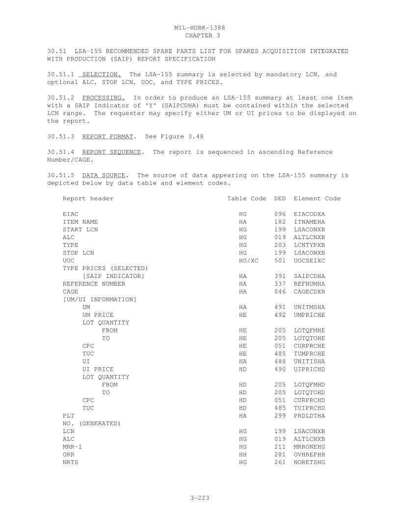
CHAPTER 3MIL-HDBK-1388
3-223
30.51 LSA-155 RECOMMENDED SPARE PARTS LIST FOR SPARES ACQUISITION INTEGRATEDWITH PRODUCTION (SAIP) REPORT SPECIFICATION
30.51.1 SELECTION. The LSA-155 summary is selected by mandatory LCN, andoptional ALC, STOP LCN, UOC, and TYPE PRICES.
30.51.2 PROCESSING. In order to produce an LSA-155 summary at least one itemwith a SAIP Indicator of "Y" (SAIPCDHA) must be contained within the selectedLCN range. The requester may specify either UM or UI prices to be displayed onthe report.
30.51.3 REPORT FORMAT. See Figure 3.48
30.51.4 REPORT SEQUENCE. The report is sequenced in ascending ReferenceNumber/CAGE.
30.51.5 DATA SOURCE. The source of data appearing on the LSA-155 summary isdepicted below by data table and element codes.
Report header Table Code DED Element Code
EIAC HG 096 EIACODXA ITEM NAME HA 182 ITNAMEHA START LCN HG 199 LSACONXB ALC HG 019 ALTLCNXB TYPE HG 203 LCNTYPXB STOP LCN HG 199 LSACONXB UOC HO/XC 501 UOCSEIXC TYPE PRICES (SELECTED) [SAIP INDICATOR] HA 391 SAIPCDHA REFERENCE NUMBER HA 337 REFNUMHA CAGE HA 046 CAGECDXH [UM/UI INFORMATION] UM HA 491 UNITMSHA UM PRICE HE 492 UMPRICHE LOT QUANTITY FROM HE 205 LOTQFMHE TO HE 205 LOTQTOHE CPC HE 051 CURPRCHE TUC HE 485 TUMPRCHE UI HA 488 UNITISHA UI PRICE HD 490 UIPRICHD LOT QUANTITY FROM HD 205 LOTQFMHD TO HD 205 LOTQTOHD CPC HD 051 CURPRCHD TUC HD 485 TUIPRCHD PLT HA 299 PRDLDTHA NO. (GENERATED) LCN HG 199 LSACONXB ALC HG 019 ALTLCNXB MRR-1 HG 211 MRRONEHG ORR HH 281 OVHREPHH NRTS HG 261 NORETSHG

CHAPTER 3MIL-HDBK-1388
3-224
MAINTENANCE TASK DISTRIBUTION CBD HG 214 CBDMTDHG CAD HG 214 CADMTDHG TOT QUANTITY RECOMMENDED HG 453 TOTQTYHG
CHAPTER 4MIL-HDBK-1388
4-1
LSAR SOFTWARE VALIDATION
40.0 OBJECTIVE. Provide guidance on MIL-STD-1388-2B software validation.
40.1 General. MIL-STD-1388-2B, 28 Mar 91, DOD Requirements for a LogisticSupport Analysis Record, cites the requirement for performing activities touse a validated LSAR ADP system. Paragraph 4.2.2.2 of the standard definesthe minimum design criteria for such a software system. Validation will becompleted by the USAMC Logistic Support Activity (LOGSA). Validation of theseindependently developed LSAR ADP systems is not, and shall not be construed asa Government endorsement of an ADP system’s design or capability. It is simplyrecognition that the vendor or performing activity software system satisfiesthe minimum LSAR ADP system requirements and criteria established by thestandard and is, therefore approved for use in support of government contractLSAR requirements.
40.2 Purpose. This handbook describes the validation process to be followed,and the requirements the vendor or performing activity developed LSAR ADPsystem must satisfy to acquire system validation.
40.3 Differences in Validation Requirements with the Revised Standard. UnderMIL-STD-1388-2A there is Government furnished software called the JointService LSAR ADP system--developed by the DOD LSA Support Activity andfurnished free of charge to any agency/contractor requesting it. The oldstandard also encouraged the use and development of independently developedLSAR ADP systems which were categorized as three different types:
40.3.1 Type I. Type I systems are "front-end" entry and edit systems only,which created transactions for processing by the government developed LSAR ADPsystem.
40.3.2 Type II. Type II systems carry this process further by independentlycreating complete and transferable LSAR Master Files. Reports are generatedusing the report generation sections of the government developed LSAR ADPsystem.
40.3.3 Type III. Type III systems are "full blown" and completelyindependent LSAR ADP systems with the capability of independent reportgeneration and data transfer using the complete LSAR master files.
Under MIL-STD-1388-2B, there is no Joint Service Standard ADP system, on whichto build independent ADP system. Therefore, all independent ADP systems aresimilar to type III. Additionally, validated systems must be capable oftransferring and accepting change only data from the last delivery of LSARdata and providing automated user comment capability.
40.4 Differences in LSAR Software System Design Criteria 2A versus 2B. Thenew capabilities of the 2B designed LSAR system are a large improvement overthe 2A capabilities. These new capabilities were desired by both the

CHAPTER 4MIL-HDBK-1388
4-2
government and contractors. Therefore, these new capabilities must be part ofthe validation criteria. The differences in the 2A verse 2B validationcriteria, see figure 4.1, are as follows:
40.4.1 Master Table(s) Acceptance. A new criteria requires capability toautomatically accept relational master table data in the formats described inappendix A (MIL-STD-1388-2B) using the data elements, definitions, dataelement edits, data field lengths, and data relationships contained inappendices A and E of the standard (MIL-STD-1388-2A does not require theacceptance of master files).
40.4.2 Master Table(s) Delivery. The ADP system must have the capability ofoutputting LSAR relational tables as displayed in Appendix A,(MIL-STD-1388-2B) to satisfy the Data Item Description format for datadelivery. (Criteria unchanged from 2A to 2B, only data is in relational table format, instead of master file format).
40.4.3 LSAR Reports. All 2B ADP system are required to produce all LSAR reports, including all options and selection criteria as displayed anddescribed in Appendix B, MIL-STD-1388-2B. (MIL-STD-1388-2A requirement for aType III system was to produce at least one or more of the standard LSA outputreports.)
40.4.4 Appendix A and E. The system must satisfy the business rulesestablished in Appendix A of MIL-STD-1388-2B. The system must, as a minimum,have the capability of satisfying appendix E, (MIL-STD-1388-2B) data elements
FIGURE 4.1

CHAPTER 4MIL-HDBK-1388
4-3
definitions. (Criteria unchanged from Appendix F of MIL-STD-1388-2A, only there have been new data elements added.)
40.4.5 Change Only Data. The system must have the capability of outputtingand inputting change only data. Change only data is that data which isdifferent from last delivery of data. (MIL-STD-1388-2A could accept full filetransfers only; it did not specify the requirement for change only data.)
40.4.6 Comment Capabilities. The system must have the capability to provideautomated user comments. MIL-STD-1388-2B does not specify how the commentcapability be done, only that it must be automated. (This capability was notavailable under MIL-STD-1388-2A.)
40.5 General Validation Procedures. The following describes the testparameters and step by step validation process. Additional and more detailedinstructions of the validation procedures are available from LOGSA in the formof a Validation Guide, provided upon request.
40.5.1 Step 1. The system developer will submit a written validation requestto LOGSA, the DOD LSAR Support Activity.
40.5.2 Step 2. LOGSA then forwards test data and instructions to the systemdeveloper. Testing parameters for the system include:
(1) Evidence of integrity between tables.
(2) Correct data edits.
(3) Establishment of records with full record identification
(4) Recognition of business rules, e.g., in table BD, if you have afailure rate, you must have a failure rate measurement base.
(5) Accepting and producing change only data.
(6) Accepting and producing Master tables.
40.5.3 Step 3. The test data is uploaded to the developer’s system. Themodules must be processed in their numerical sequence. The modules containinitial input to all master tables in Cycle 1, updates in Cycle 2, and validand invalid manual transactions in Cycle 3.
40.5.4 Step 4. After running Cycle 1, hardcopies of the LSAR reports aregenerated from the master tables. The Government validation team will performa comparison of each LSA hardcopy report generated from the master tablesproduced by the system developer. Validation requires that the LSA productoriented reports such as the MAC, RPSTL, and 036, Provisioning Requirements beidentical in format and content to those displayed in Appendix B, MIL-STD-1388-2B; while other summary reports such as the LSA-001, Man-Hours bySkill Specialty Code and Level of Maintenance, LSA-003, Maintenance Summary,and the LSA-005, Support Items Utilization Summary are reviewed only for

CHAPTER 4MIL-HDBK-1388
4-4
content, spacing, etc. is not considered critical, but the general format ofthe report should be adhered to.
40.5.5 Step 5. The system developer must then submit the following items toLOGSA for validation:
(1) LSAR data tables on 5 l/4 or 3 1/2 inch floppy disk followingCycle 3.
(2) Change only LSAR data reflecting changes caused by Cycle 2 andCycle 3 test data to the initial cycle.
(3) Hardcopy listing and floppy disk of LSAR reports in sequence asshown in Appendix B, MIL-STD-1388-2B.
(4) Report of entry/edit discrepancies for Cycles 1 and 2 .
(5) Completed survey contained in Appendix A, MIL-STD-138 8-2B,Software Validation Guide. Data contained in this survey may be released toLSAR users requesting information on validated LSAR software systems.
40.5.6 Step 6. LOGSA will contact the developer if any validationdiscrepancies are discovered that are not explained in his validation reportand survey. In addition, direct access to that system via modem, or on-siteinspection, for automated edit or user comment capability review may berequested.
40.6 Validation Completion. LOGSA evaluates the LSAR products submitted. Assuming no major problems are encountered in the validation process, up to 60working days may be required for review after initial submission of thevalidation request and accompanying files, listings, survey, and report.Upon successful completion of the system’s validation review, the developerwill receive an official letter of validation from the Office of the AssistantSecretary of Defense (Defense Logistic Support Office).
40.7 Validation Letter Renewal Procedures. Under MIL-STD-1388-2B a letter ofvalidation issued to any independently developed LSAR ADP system is renewableannually on the anniversary date of the letter currently in effect. MIL-STD-1388-2A validations no longer require renewals.
40.7.1 Renewal Request. The system developer must request renewal, inwriting, to LOGSA, the DOD LSAR Support Activity. The request must include: the date of the current letter of validation and a statement clearlyconfirming that the LSAR ADP system has not been modified from the initialdescription submitted for validation.
40.7.2 Renewal Issuance. The DOD LSAR Support Activity requires 15 workingdays to process validation renewal requests. These requests are forwarded toOASD, where the official renewal letter is mailed to the system developer anda copy furnished to LOGSA.

CHAPTER 4MIL-HDBK-1388
4-5
40.8 LSAR ADP System Revalidation. Revalidation is mandatory if a system isaltered from that which is described in the validation request letter on filein the DOD LSA Support Activity. It is the responsibility of the independentsystem developer to apply for revalidation. Revalidation procedures and theprocessing time table are identical to those described in paragraphs at 1.5for initial system validation. Revalidation requests received within 120 daysof a previously validated or renewed system will not be honored.
40.9 Disapproval of Validation Request. If an LSAR ADP system failsvalidation, its developer will be informed of the reason(s) for failure andrecommended corrective action(s) to facilitate system validation.
40.10 Revocation of Validation. There are endless combinations of data editsand business rules to be adhered to in developing this type of ADP system.With the expertise of our validation team and high standards for ourvalidation process, hopefully, the result will be the availability of someexcellent quality MIL-STD-1388-2B software. However, if a vendor demonstratesnoncompliance with these standards or continually exhibits problems within hissystem that are not corrected, he risks revocation of his validation.
40.11 Considerations for Software Evaluation. Listed below are some suggestedareas to think about in evaluating the LSAR software available, and help youin determining the one(s) that best suit your particular needs:
a. Type of hardware platform to be used, (mainframe, mini, etc.).
b. Volume of data to be documented.
c. Rate of processing (number of transactions).
d. Types of users/operators--user friendliness.
e. Number of simultaneous users.
f. Interface requirements to other systems.
g. Conversion capability from MIL-STD-1388-2A to MIL-STD-1388-2B.
h. Cost of the system.
i. Ad hoc reporting capability.
j. Any other special requirements you may need.
40.12 LSAR Independently Developed ADP Pamphlet. LOGSA also produces apamphlet on LSAR Independently Developed ADP Systems. This pamphlet containsa brief description of each of the independently developed LSAR softwareprograms that have been validated by LOGSA. This brochure is periodically updated to reflect both systems validated under MIL-STD-1388-2A as well as thefuture MIL-STD-1388-2B systems.
Chapter 5MIL-HDBK-1388
5-1
GUIDANCE FOR ASSIGNMENT OF LOGISTIC SUPPORT ANALYSIS (LSA) CONTROL NUMBER (LCN), ALTERNATE LCN CODE (ALC), LCN TYPE AND USABLE ON CODE (UOC)
50. PURPOSE. This chapter provides guidance for the assignment of LCNs,ALCs, LCN-Types, and UOCs; their use; and, their relationship to one another.
50.1 Traditional LCN assignments. Traditionally, the LCN was developed usingthe physical hardware configuration (or engineering drawings), for LCNassignment. Using this approach, the LCNs assigned directly tracked withprovisioning documentation requirements, and enabled easy conversion toprovisioning data keys (PLISN). Any product documentation, such as theMaintenance Allocation Chart, Maintenance Plans, or Repair Parts and SpecialTools List requiring a Functional Group Code (FGC) or Work Unit Code (WUC)sequencing was selected by LCN and then resorted by the data elementWUC/TM-FGC.
50.2 Functional and physical LCN assignments. Under MIL-STD-1388-2B, thecapability exists to assign physical and/or functional LCNs. The functionalbreakdown of the system is useful for rolling up RAM type of information andalso for documenting reliability allocation. Under the Reliability andMaintainability areas, a physical hardware breakdown may create problems in"rolling up" failure rates, reliability times, and maintainability frequenciesto the appropriate higher item. For example, if an antenna connected to awing-tip fails, the failure should be rolled to the communications system, andnot to the wing structure on which it is physically attached. The traditionalWUC/TM-FGC cannot be used for functional documentation since this element isused for product development and may contain a consolidated code for "like"items which will create problems for reliability/ maintainability summationsand calculations. In addition, a WUC/TM-FGC cannot be documented until aphysical (or traditional) LCN has already been assigned. The functional LCNwill provide the flexibility necessary to correct these situations. In caseswhere the functional and physical breakdown are identical, separate structureswill not be required. When there is a requirement for both physical andfunctional breakdowns, a cross-reference table mapping the functional andphysical LCNs (table XG) will be documented to link the two. There can onlybe one physical LCN per functional LCN, and vice-versa. In an automated dataprocessing system, the physical LCN structure will take precedence for datastorage, when both a physical and functional LCNs exist for the same item.Upon creating the physical/functional mapping, any data documented under afunctional LCN will be converted from a functional to a physical key. It isimportant to recognize that the two structures are completely independent, andthat a "mixing" of structures (part physical/part functional) for a system/enditem is not permitted. Also recognize the importance of proper mapping of thefunctional and physical LCNs. Figure 5.1 provides an example of a comparisonbetween a physical and functional LCN breakdown. Note that the LCN for theantenna is A0301A on the functional breakdown and is A0101 on the physicalbreakdown. If reliability data had already been developed against thefunctional LCN and you now want to relate that information to a part in thephysical breakdown, all you would have to do is use the mapping table (tableXG) to document that the functional LCN A0301A and the physical LCN A0101 arethe same item. Also note that the functional and physical LCNs are at

Chapter 5MIL-HDBK-1388
5-2
figure 5.1

Chapter 5MIL-HDBK-1388
5-3
different indenture levels, but they can still be mapped to each other.
50.2.1 LCN Type. To document functional/physical LCN assignment requires anew data element, LCN Type. This element is a key and is required where allLCN oriented data resides. The LCN-Type is a one-position code of either "F",Functional; or "P", Physical. One note of caution, if provisioning data isrequired for your system/equipment, Physical LCNs must be assigned becausetables HG through HR require a physical breakdown.
50.3 LCN ASSIGNMENT. The LCN may represent either a functional or hardwaregeneration breakdown/disassembly sequence of system/equipment hardwareincluding support equipment, training equipment, and installation (connecting)hardware. As such, the LCN is a key field utilized to input data into theLSAR data system and to extract reports from the data system. Normally,development of the LCN structure and assignment of LCNs through the subsystemlevel should be accomplished prior to completion of the first LSAR datatables. Extreme care should be exercised in developing the structure, so thatthe least number of characters is used for each indenture level. This can beaccomplished by identifying the maximum number of parts/assemblies which willbe assigned a unique LCN at each indenture level. A special caution needs tobe mentioned regarding the use of special characters in LCN assignment; ifpossible, do not utilize special characters when assigning LCNs. The reasonfor this warning is different ADP systems utilize special characters indifferent ways. Although your ADP system may allow a certain set of specialcharacters for LCN assignment, another ADP system which your data may bepassed to may use some of those special characters in system administration,and, therefore, produce critical errors when reading in LCNs with thosespecial characters. If the maximum number of items at a given indenture levelis less than or equal to 36, then 1 alphanumeric character would suffice. Ifthe maximum number of items is greater than 36 but less than or equal to 1296,then 2 alphanumeric characters would suffice and so on. No more than oneposition of the LCN should be used to identify the system. It is useful todevelop an LCN structure for the entire system/equipment hardware. Careshould be exercised in assigning the LCNs, since the order in which they areassigned will affect the order of FMECA data and task analysis information,and may affect the order in which it will be used on a repair parts lists andassignment of PLISNs. For example, if it is a requirement for attachinghardware to appear on a repair parts list prior to the assembly, these itemswould have to be assigned LCNs which are less in value than the one assignedto the assembly. In assigning the LCN early in the design of an end item, itis also advantageous to skip one, two,or more LCNs, so that an additional itemcan be inserted later on due to design changes. This advance planning avoidsthe possibility of having to resequence at a later point in the program. Figure 5.2 provides an example of a developed LCN structure. In this example,we allocated 1 character at the A indenture level; the second indenture levelB was allocated 2 spaces; the third level (the C indenture level) we allocated3; the D level 3; the E level 4; and down at the piece part level we allocated5 characters to document the LCN. Therefore, our LCN structure for thisexample is 1,2,3,3,4,5. If there is a 3 position LCN, then the ADP systemwill recognize that we must be at the B indenture level. Likewise, a 6character LCN must be at the C indenture level. The total sum of thepositions in the LCN structure

Chapter 5MIL-HDBK-1388
5-4
figure 5.2

Chapter 5MIL-HDBK-1388
5-5
cannot exceed 18, that is the maximum number of characters available for LCNassignment. The above guidance should be considered prior to assigning theLCNs. Three basic methods for assigning LCNs are discussed below, but you arenot limited to these methods.
50.3.1 Classical LCN assignment. This method dictates assignment of a uniqueLCN to every application of a part numbered item in the system including pieceparts. This method ensures proper identification of an item to its NextHigher Assembly (NHA) and ensures proper roll-up/summarization of data for allLSA Record (LSAR) reports. Figure 5.3 is an example of the classical LCNassignment method. From a provisioning standpoint, use of the classicalassignment method would allow the automatic assignment of PLISN, NHA PLISN,SAME AS PLISN, and Indenture Code.
50.3.2 Modified classical assignment method. This method is a variation ofthe classical assignment method, which permits piece parts to be assigned thesame LCN at the indenture level below the component/assembly of which they area part. In addition, attaching hardware may be assigned the same LCN at thesame indenture level at which the assembly is located. The assembly to whichthe attaching hardware is required is provided a separate LCN. Figure 5.4shows an example of the modified classical method. The items with an asteriskhave been assigned the same LCN. Application of this method could economizethe number of LCNs required at the lower indenture levels. Use of this methodensures proper roll-up/summarization of data for all LSAR reports. From aprovisioning standpoint when hardware breakdown approach is used for the LCN,this method allows the automatic assignment of all PLISNs and the indenturecode.
50.3.3 Sequential assignment method. For large systems, an attempt to useany of the above methods can still result in a need for more than the 18characters allocated to the LCN field. In this situation, the classical ormodified classical assignment method would be employed for the first 12 or 13characters of the LCN field; the last five or six characters of the LCN fieldwould be assigned sequentially through the remaining indentures. An exampleof the sequential assignment method is provided on figure 5.5. This methoddoes not affect the normal processing of the LSAR output reports; however, itis necessary to select reports at indenture levels above the point wheresequential assignment of LCNs was initiated. From a provisioning standpoint,this method dictates manual input of the LCN-indenture code (LCN-IC) in orderto automatically assign PLISN, NHA PLISN, and Indenture Code.
50.4 ALTERNATE LCN CODE (ALC). The ALC (codes 00 through 99) provides thecapability to document alternate design concepts or like items for differentmodels using identical LCNs at the same system breakdown level. As such, ALCis a key data element and a value of 00 is considered just as significant as avalue of 01, 10, or 23. In fact, all LCNs which have a corresponding ALC witha value of 00 represent the "basic system" hardware. The ALC is LCN orientedand is used to aid in the documentation of the following:
a. Alternate items with different reference numbers (e.g., diesel engineversus gas engine), one of which will be selected for production.

Chapter 5MIL-HDBK-1388
5-6
figure 5.3

Chapter 5MIL-HDBK-1388
5-7
figure 5.4

Chapter 5MIL-HDBK-1388
5-8
figure 5.5
Chapter 5MIL-HDBK-1388
5-9
b. Different reference numbered items which are used in the samefunctional and physical location (i.e., same LCN) in the hardware breakdown,and the usage of either item results in a different configuration/modeldesignation (i.e., different UOCs).
The use of ALC for a single configuration/model is discussed in theimmediately following paragraphs, while ALC usage for multipleconfigurations/models is discussed in paragraph 3.
50.4.1 ALC usage for a single configuration/model. A system/end item whichhas a single configuration/model designation will have only one assigned UOC.When a system/end item has a single UOC, then the ALC can be used to captureanalysis data for alternative designs or maintenance concepts. To properlyinput LSAR data and establish a traceable LCN breakdown structure, thefollowing rules should be adhered to:
a. Rule 1. The "basic system" hardware breakdown must be input using ALCvalues of 00. This is necessary since the selection process will alwaysdefault to the "basic system" data, if alternative data has not been entered.
b. Rule 2. Alternative designs will be broken down completely in termsof LCN and associated data.
c. Rule 3. To the maximum extent possible, the ALC assigned should bethe same value throughout the alternative design/maintenance concept.
Following these rules allows for an orderly buildup of LSAR data and avoidsconfusion concerning which items may be common to two or more alternatives andprovides for easier retrieval of LSAR reports.
50.4.1.1 Figure 5.6 is an example of a single configuration/model end itemwith a UOC of "ABC". The example also represents how the ALC can be used foralternative hardware design concepts. Three different fuel pumps are beingconsidered for use on the gas engine, as well as an alternative diesel engine.All "basic" hardware items have an ALC of 00, while two additional fuel pumpsand the entire diesel engine breakdown have different ALCs. This is inaccordance with the first rule stated above. Rule 2 is also followed for thefigure xx breakdown of the diesel engine because the identical electricalsystem was repeated from the gas engine. Rule 3 is followed in assignment ofALCs for the diesel engine (the multiple fuel pumps and their ALC assignmentsare an example of the Rule 3 statement "To the maximum extent possible ...").
50.4.2 ALC usage for LSAR reports. For most report selections, the UOC isalways the first criteria that must be met for data selection and LCN is thesecond criteria. ALC becomes the third select criteria, if the user specifiesa specific ALC value on the report request. As already discussed, an ALC of00 on the report submittal will result in choosing "basic system" LCN data(i.e., records with 00 ALCs). If an ALC is requested with a specificnumeric value, only items with a matching ALC will be chosen. If no ALC valueis selected (blank), any ALC value can be chosen.

Chapter 5MIL-HDBK-1388
5-10
figure 5.6
Chapter 5MIL-HDBK-1388
5-11
50.4.3 Lower-tiered LCN/ALC selections. In addition to the basic reportrequest, different LCN and ALC combinations at a lower indenture level fromthe basic report selection may be chosen to specify the alternative designdesired by identifying these LCNs and ALCs. This is necessary when rule 3,discussed in paragraph 2.1, cannot be strictly adhered to and designation ofthe ALC on the basic report request will not result in a complete substitutionof the alternative design. This situation will occur when alternative designsare being considered within the hardware breakdown of another alternativedesign. The example on figure 5.6 displays this situation; alternative fuelpumps are being considered within the gas engine and two alternative enginesare being considered. Thus, in order to obtain the "basic system" (i.e., withgas engine), but with fuel pump RN5, a lower-tiered LCN/ALC request selectionmust be input with an LCN of "A203" and an ALC of "03". The basic reportrequest would have an ALC value of 00. In order to produce a report for the"basic system" with the diesel engine substituted, the following selectionrequest would be required:
a. A basic selection request with an LCN of "A", UOC of "ABC", and an ALCof "00". This produces a report of the "basic" truck.
b. A lower-tiered LCN/ALC selection request with an LCN of "A2" and anALC value of "01". This information would modify the basic selection requestto choose the diesel engine and its components, in lieu of the gas engine.
The lower-tiered LCN/ALC selection request allows the user to create manydifferent variations of a system/end item via the LSAR reports. While use ofthe ALC for alternative designs does not reduce the amount of data required(i.e., rule 2 of paragraph 30.1), it does provide for easier data storage andreport generation.
50.5 USABLE ON CODE (UOC). The UOC is used to identify the model/configuration relationship of each LCN comprising a system/equipment and tocontrol these relationships for LSAR report generation. The UOC is a criticaldata element and should therefore be used when establishing an LSAR. Thisrequirement holds even if only one configuration/model of a system/equipmentis being documented. In accordance with table XC, contained in appendix A ofMIL-STD-1388-2B, each configuration/model is assigned a unique UOC at thesystem/end item level LCN. Each individual assembly/component/piece part isalso "linked" to the assigned UOC of the model of which it is applicablethrough tables XF and HO. When an assembly/component/piece part is applicableto more than one configuration/model, then multiple UOCs are "linked" to thecomponent for a single LCN and ALC via tables XF and HO. This eliminates therequirement of duplicating analysis and related data, merely because an itemhas application to multiple configurations/models. It should be stressed thatif an item’s usage for a given configuration model differs from anotherconfiguration/model in terms of quantity, Source, Maintenance, Recoverability(SMR) coding or analysis data, then multiple UOCs should not be used for asingle LCN. This situation dictates using the ALC to indicate different datafor the same LCN and a different UOC.
50.5.1 ALC and UOC relationship. In order to document multipleconfigurations/ models in the LSAR, the ALC plays an important role. As

Chapter 5MIL-HDBK-1388
5-12
already stated, for items that are common to all configurations/models, onlyone LCN/ALC entry is required in table XB for the multiple UOCs (table XF willhave multiple entries, one entry per UOC). In addition, since such an item isconsidered part of the "basic system", its ALC would be 00. For those itemsthat bring about a configuration/model change, the ALC is used in a mannersimilar to that discussed in paragraph 50.4. Figure 5.7 is an example ofmultiple UOCs for a given system/end item and the usage of ALC in conjunctionwith multiple model items. In the example, the basic model truck has a UOC of"ABC", while the new model truck has a UOC of "ABD". The reason for theadditional model is the use of a diesel engine, instead of the gas engine. Since both types of engines physically and functionally appear in the samelocation of the truck breakdown, their LCNs are the same. The ALC of "01" hasbeen used to differentiate new reference numbered items from the basic items.
50.5.2 UOC and ALC usage for LSAR reports. Paragraph 50.4.2 states that mostselection requests for the LSAR reports must have, as a minimum, LCN and UOCon the request. The reason for this is that UOC is the overall reportgeneration key that must match to a record before LCN and ALC are considered. In the case of a single configuration/model, its importance is reduced sinceevery item has the same UOC value. For multiple configurations/models, theidentification of the desired UOC on the selection request will result inbuilding the desired output LSAR reports without lower-tiered LCN/ALCselections and without knowing which ALC values were used for that UOC’s LCNs. Using the example on figure 5.7, a report selection request with an LCN of"A", an ALC of 00, and a UOC of "ABC" will result in the basic model breakdownbeing output. This means that the fuel pump, with reference number RN7, wouldbe chosen over the other two fuel pumps. If the report selection request hadbeen LCN of "A", a blank ALC, and UOC of "ABC", all items containing the UOC"ABC" would be selected. Therefore, all three fuel pumps under the basicmodel would be output. If the second model of the truck with UOC of "ABD" isto be selected, a report selection request with an LCN of "A" and a UOC of"ABD" is all that is needed. This would result in all LCN items with UOCvalues of "ABC" and "ABD", as well as all LCN items with UOC of "ABD" onlybeing selected. In effect, the basic model with the diesel engine substitutedwould be output for the desired reports. What this selection should pull outis the diesel model truck, diesel engine, block, fuel pump, and it should alsopull out from the basic model the body, transmission, and electrical system.
50.6 SUMMARY. The assignment of LCNs, UOCs, and ALCs must be approachedcarefully and logically in order to ensure that the LSAR reports represent thehardware logistics data desired. In general, a system/end item developmenteffort normally begins with a single model designation (i.e., one UOC).During this phase of development, the ALC is needed only when alternativedesigns are being considered. As the hardware design stabilizes, the"undesirable" alternatives are deleted from the LSAR database in favor of"basic system" configuration. Once a system/end item enters the productionphase, engineering change proposals, because of producibility limitations,design deficiencies, or changes in operational requirements, can dictate a newconfiguration model. When this occurs, the ALC once again would be used toaid in the documentation effort. This orderly application of the ALC to

Chapter 5MIL-HDBK-1388
5-13
figure 5.7
Chapter 5MIL-HDBK-1388
5-14
alternative design/maintenance concepts or multiple configuration/models canpreclude user confusion. It is possible that some system/end itemdevelopments will initially be faced with documenting multiple configurations/models and alternative design/maintenance concepts, simultaneously. When thisoccurs, an orderly and logical approach to UOC and ALC, following the guidanceof this chapter, will result in a properly documented system/end item.

CHAPTER 6MIL-HDBK-1388
6-1
60. ACTIVITY AND DATA MODELING
60.1 Activity Modeling. In today’s environment, the importance ofidentifying and managing data as a resource has been well documented. Thetraditional approach, activity modeling, has been to identify the activitiesrequiring data and then to develop an application system to meet the need ofthe activity. The result has been a legacy of programs, files, and databasesthat are not integrated. In addition, data are inconsistent and unreliablesince there are multiple sources of data.
60.2 Data Modeling. The modern approach utilizes activity modeling and datamodeling. Activity modeling is used to identify data; data modeling is used todefine the data structure. The process of modeling the organization’s dataidentifies, defines, and graphically portrays these data as well as therelationships. Once the data have been modeled and verified by the usercommunity, an organization will have a better understanding of the data’smeaning and usage. Data that may have been process-bound in the past nowbecomes shared data, data that may be useful to multiple areas.
60.3 LSAR Data Model. The data modelingtechnique used for theLSAR was a top-down,entity-relationshipconcept. This was basedon a relational concept,group or set theory. These concepts includeentity identification,key and non-key attributedefinition, andidentification ofintegrity constraintsbetween pairs ofentities. These conceptsprovide a base fornormalizing the datamodels. Figure 6-1depicts an excerpt of thedata model developed forthe LSAR. Shown are theentity names, keyattributes, non keyattributes, andrelationships betweenentities. Entities namea class of real orabstract objects. EntityEnd Item Acronym (EIA) isused to identify theobject, while entity LCN
Figure 6-1
CHAPTER 6MIL-HDBK-1388
6-2
Indentured Items is used to identify the different LCNs needed for the object. EIA is an independent entity depicted by a box, which means the entity is notdependent upon another entity. Entity LCN Indentured Item depicted by arounded corner box is a dependent entity relying upon the EIA entity key forits identity. The relationship between the two entities identifies thatentity EIA "names" the entity LCN Indentured Item. The entity EIA has onlyone key attribute. Key attributes are defined as one or more attributes thatuniquely define an instance of an entity. Attributes represent thecharacteristics or properties of an entity. Non Key attributes are notconsidered as specifically required to identify an entity and rely upon thekey attributes to uniquely define them for an entity. The key attribute forthe entity EIA is the EIA Code (EIAC). The non key attributes for entity EIAconsist of numerous data elements which will be called LORA Information infigure 6-1. The set of attributes that uniquely identify the LCN IndenturedItem entity is LCN, ALC, LCN Type, and the foreign key attribute of EIAC. EIAC has migrated from the EIA entity and is needed to uniquely identify theinformation in the LCN Indentured Item entity. Non Key attributes identifiedfor the entity LCN Indentured Item are LCN Indentured Code, LCN Structure, EndItem Container Size, Non Self Propelled Handling Type, Tracked Wheeled TowingSpeed, System End Item Identifier, Non Self Propelled Skid RequirementNarrative, Self Propelled Remarks Narrative, and Tracked Wheeled TowingNarrative. This set was identified as attributes that are specifically tiedto the key attribute set, which means that when the key set changes the nonkey attributes can change also. The LSAR data model represents to the thirdnormal form the data captured in the LSAR. What is shown in figures 6-2through 6-11 are the data model entity names, key attributes to uniquelyidentify the entity, and the relationships between the entities.
60.3.1 Normalization. When data models are developed, the optimal result isto avoid the problems caused by data redundancy, incorrect path assertions,and incorrect data definitions such as repeating groups and no-nullconstraints. The result is achieved by designing data structures that arenormalized to third normal form. This means that each attribute resides inonly one place in the model, has only one value, and that it depends entirelyupon the full key of the entity for its existence.

CHAPTER 6MIL-HDBK-1388
6-3

CHAPTER 6MIL-HDBK-1388
6-4

CHAPTER 6MIL-HDBK-1388
6-5

CHAPTER 6MIL-HDBK-1388
6-6

CHAPTER 6MIL-HDBK-1388
6-7

CHAPTER 6MIL-HDBK-1388
6-8

CHAPTER 6MIL-HDBK-1388
6-9

CHAPTER 6MIL-HDBK-1388
6-10

CHAPTER 6MIL-HDBK-1388
6-11

CHAPTER 6MIL-HDBK-1388
6-12

CHAPTER 6MIL-HDBK-1388
6-13
60.4 Implementation of the LSAR Data Model for MIL-STD-1388-2B. When adata model is develop into afunctional computer programthere is a chance that someof the normalization islost. This maybe done forADP processing performanceor in MIL-STD-1388-2B’s casefor usage of data. Figure6-12 shows and excerpt ofthe implementation of MIL-STD-1388-2B. It was decidedthat the LCN structureshould only be identifiedonce for the entire EIAC. This would help in the ADPprocessing of the LCN’s, soit was moved from the entityLCN Indentured Item to theentity EIA. Some of the nonkey attributes; End Itemcontainer size, Non SelfPropelled Handling Type,Tracked Wheeled TowingSpeed, Non Self PropelledSkid Requirements Narrative,Self Propelled Remarksnarrative, and TrackedWheeled Towing Narrative ofthe entity LCN IndenturedItem were moved to another functional area of transportation. This was donebecause these Non key attributes will only apply to a minimal amount of LCNs. There are other cases of Non Key Attributes being moved to increaseperformance of the ADP system. MIL-STD-1388-2B identifies the implementationof the LSAR data model.
Figure 6-12

APPENDIX AMIL-HDBK-1388
A-1
APPENDIX AACRONYM LISTING
AAL Additional Authorization ListADP Automatic Data ProcessingAF Air ForceAFMC Air Force Material CommandALC Alternate Logistic Support Analysis Control Number CodeALUR Automated Logistic Support Analysis Record Utilities RoutinesAMC Amry Material CommandARN Additional Reference NumberBIIL Basic Issue Items ListBIT Built In TestBITE Built In Test EquipmentBOI Basis of IssueCAGE Commercial and Government Entity codeCBIL Common and Bulk Items ListCCSS Commodity Command Standard SystemCDRL Contract Data Requirements ListCED Concept Exploration/DefinitionCFI Card Format IndicatorCIC Critical Item CodeCM Corrective MaintenanceCMRS Calibration and Measurement Requirement SummaryCOEA Cost and Operational Effectiveness AnalysisCOEIL Components Of End Item ListCSC Card Sequencing CodeCSN Card Sequence NumberDARS Defense Acquisition Regulation SupplementDCN Design Change NoticeDID Data Item DescriptionDLSC Defense Logistics Services CenterDOD Department of DefenseDODISS Department of Defense Index of Specifications and StandardsD&V Demonstration and ValidationEBCDIC Extended Binary Coded Decimal Interchange CodeEDFP Engineering Data for ProvisioningEIAC End Item Acronym CodeEMD Engineering and Manufacturing DevelopmentESML Expendable/Durable Supplies and Materials ListFGC Functional Group CodeFMEA Failure Modes Effects AnalysisFMECA Failure Modes Effects and Criticality AnalysisFOI Functional Operating InstructionsGFE/GFI Government Furnished Equipment/Government Furnished InformationHFE Human Factors EngineeringIC Indenture CodeICC Item Category CodeICTP Individual and Collective Training PlanILS Integrated Logistic SupportILSP Integrated Logistic Support Plan

APPENDIX AMIL-HDBK-1388
A-2
IMAC Industrial Materials Analysis of CapacityIPB Indentured Parts BreakoutIPS Integrated Program SummaryISIL Interim Support Items ListJCL Job Control LanguageLCC Life Cycle CostsLCN Logistic Support Analysis Control NumberLLTIL Long Lead Time Items ListLOGPARS Logistics Planning and Requirements Simplifications SystemsLORA Level of Repair AnalysisLSA Logistic Support AnalysisLSAP Logistic Support Analysis PlanLSAR Logistic Support Analysis RecordMAC Maintenance Allocation ChartMARC Manpower Requirements CriteriaMB Measurement BaseMCCDC Marine Corps Combat Development CommandMCSC Marine Corps Systems CommandMD Material DeveloperMNS Mission Need StatementMPT Manpower, Personnel, and TrainingMRR Maintenance Replacement RateMTBF Mean Time Between FailuresMTD Maintenance Task DistributionNAVAIR Naval Aviation CommandNAVSEA Naval Sea CommandNAVSUB Naval Submarine CommandNDI Non-Developmental ItemNHA Next Higher AssemblyNSN National Stock NumberO&M Operations and MaintenanceO&O Organizational and OperationalOPNAV Operations NavalORD Operational Requirements DocumentORR Overhaul Replacement RateO&S Operations and SupportPA Performing ActivityPBF Provisioning Baseline FilePCCN Provisioning Contract Control NumberPCL Post Conference ListP&D Production and DeploymentPERT Program and Evaluation Review TechniquePHS&T Packaging, Handling, Storage and TransportationPIP Product Improvement ProgramPL Provisioning ListPLCC Provisioning List Category CodePLISN Provisioning List Item Sequence NumberPM Preventive MaintenancePMAC Preliminary Maintenance Allocation ChartPMCS Preventive Maintenance Checks and ServicesPMF Parts Master FilePMR Provisioning Master Record

APPENDIX AMIL-HDBK-1388
A-3
PPI Planned Product ImprovementPPL Provisioning Parts ListPPLI Provisioning Parts Listing IndexPPS Provisioning Performance SchedulePPSL Program Parts Selections ListPTD Provisioning Technical DocumentationPUC Provisioning Unit of Measure Price CodeQPA Quantity per AssemblyQPEI Quantity per End ItemQQPRI Qualitative and Quantitative Personnel Requirements InformationRA Requiring AuthorityRAM Reliability, Availability, and MaintainabilityRCM Reliability Centered MaintenanceRDBMS Relational Data Base Management SystemRDOC Reference Designation Overflow CodeRFP Request For ProposalR&M Reliability and MaintainabilityRNCC Reference Number Category CodeRNVC Reference Number Variation CodeRPSTL Repair Parts and Special Tools ListRPT Resident Provisioning TeamRIL Repairable Items ListRTD Replacement Task DistributionSAIP Spares Acquisition Integrated with ProductionSCC Significant Character CodeSCN Submitter Control NumberSCPL System Configuration Provisioning ListSE Support EquipmentSERD Support Equipment Recommendations DataSESAME Selected Essential-Item Stockage for Availability MethodSFPPL Short Form Provisioning Parts ListSHSC Safety Hazard Severity CodeSIC Suppression Indicator CodeSMR Source, Maintenance and Recoverability CodeSOW Statement of WorkSPAWAR Space and Warfare CommandSPCC Ships Parts Control CenterSPS Statement of Prior SubmissionSQL Structured Query LanguageSRA Specialized Repair ActivitySR&M System Reliability and MaintainabilitySSC Skill Specialty CodeSSP System Support PackageTDP Technical Data PackageT&E Test and EvaluationTEMP Test and Evaluation Master PlanTM Technical ManualTMDE Test Measurement and Diagnostic EquipmentTM/FGC Technical Manual/Functional Group CodeTOCC Type of Change CodeTPS Test Program SetTT Technical Test

APPENDIX AMIL-HDBK-1388
A-4
TTEL Tools and Test Equipment ListUOC Usable On CodeUM Unit of MeasureUSAMC United States Army Material CommandUT User TestUUT Unit Under TestWBS Work Breakdown StructureWUC Work Unit Code

APPENDIX BMIL-HDBK-1388
B-1
APPENDIX B MIL-STD-1388-2B DATA TABLES AND REPORTS
1.0 DATA TABLES AND REPORTS
1.1 PURPOSE. This appendix is design to be used as reference to reports,data tables, and report to data table usage.
1.2 REPORT COMPARISON. Table 1 is a comparison of MIL-STD-1388-2A and MIL-STD-1388-2B reports. This table should help those familiar with MIL-STD-1388-2A reports, but are not familiar with the new set of MIL-STD-1388-2B reports.
1388-2A 1388-2B 1388-2A 1388-2B
001 & 002 001 027 027 (Changed)
003 003 028 Deleted
004 & 020 004 029,030,031,& 034 030
005 005 032 032
006 006 036 & 150 036
007 007 040-043, & 045 040
008 008 050 050
009 009 051-055 Replace by 056 & 058
010 010 060 & 061 Deleted
011 011 070 070 (Changed)
012 012 072 072
013 013 074 074
014 014 075 075 (Changed)
015 Replaced by 019 077 077
016 & 17 016 080 080
018 Deleted 100-109 Deleted
019 019 (Changed) 151 151
021 & 022 Deleted 152 152
023 023 154 154
024 024 155 155
025 & 026 025 & 026
Table 1 LSAR REPORTS MIL-STD-1388-2A TO MIL-STD-1388-2B
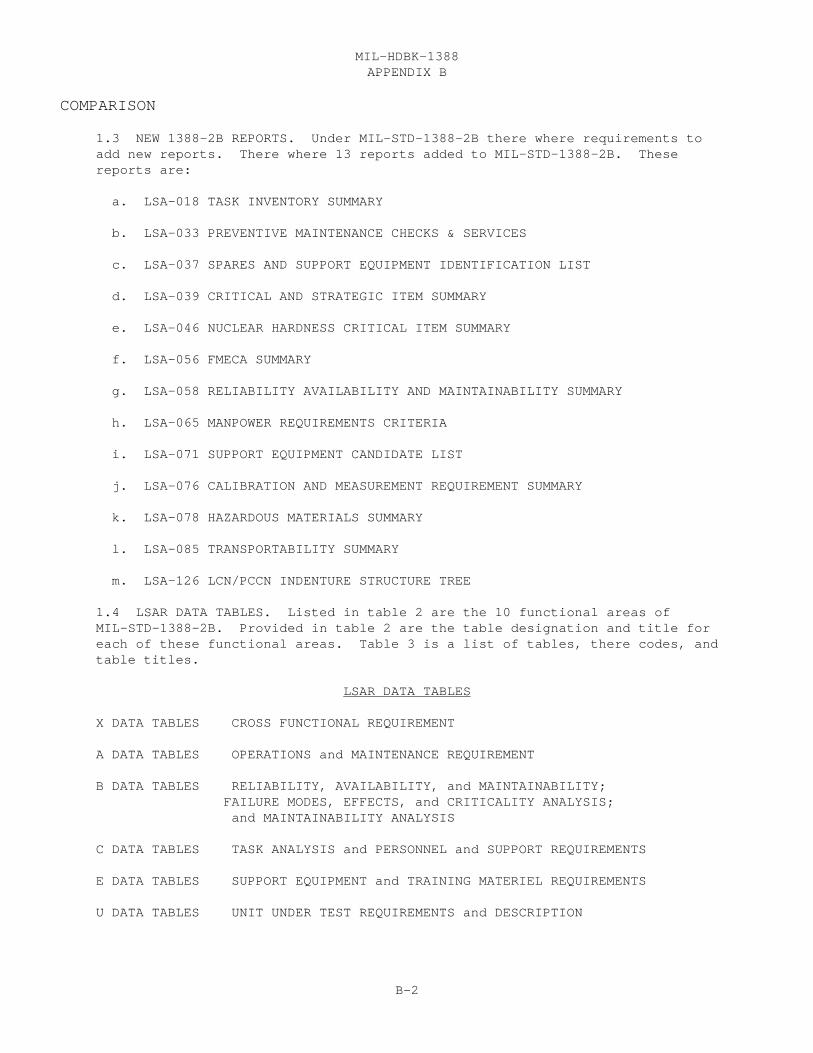
APPENDIX BMIL-HDBK-1388
B-2
COMPARISON
1.3 NEW 1388-2B REPORTS. Under MIL-STD-1388-2B there where requirements toadd new reports. There where 13 reports added to MIL-STD-1388-2B. Thesereports are:
a. LSA-018 TASK INVENTORY SUMMARY
b. LSA-033 PREVENTIVE MAINTENANCE CHECKS & SERVICES
c. LSA-037 SPARES AND SUPPORT EQUIPMENT IDENTIFICATION LIST
d. LSA-039 CRITICAL AND STRATEGIC ITEM SUMMARY
e. LSA-046 NUCLEAR HARDNESS CRITICAL ITEM SUMMARY
f. LSA-056 FMECA SUMMARY
g. LSA-058 RELIABILITY AVAILABILITY AND MAINTAINABILITY SUMMARY
h. LSA-065 MANPOWER REQUIREMENTS CRITERIA
i. LSA-071 SUPPORT EQUIPMENT CANDIDATE LIST
j. LSA-076 CALIBRATION AND MEASUREMENT REQUIREMENT SUMMARY
k. LSA-078 HAZARDOUS MATERIALS SUMMARY
l. LSA-085 TRANSPORTABILITY SUMMARY
m. LSA-126 LCN/PCCN INDENTURE STRUCTURE TREE
1.4 LSAR DATA TABLES. Listed in table 2 are the 10 functional areas of MIL-STD-1388-2B. Provided in table 2 are the table designation and title foreach of these functional areas. Table 3 is a list of tables, there codes, andtable titles.
LSAR DATA TABLES
X DATA TABLES CROSS FUNCTIONAL REQUIREMENT
A DATA TABLES OPERATIONS and MAINTENANCE REQUIREMENT
B DATA TABLES RELIABILITY, AVAILABILITY, and MAINTAINABILITY; FAILURE MODES, EFFECTS, and CRITICALITY ANALYSIS; and MAINTAINABILITY ANALYSIS
C DATA TABLES TASK ANALYSIS and PERSONNEL and SUPPORT REQUIREMENTS
E DATA TABLES SUPPORT EQUIPMENT and TRAINING MATERIEL REQUIREMENTS
U DATA TABLES UNIT UNDER TEST REQUIREMENTS and DESCRIPTION
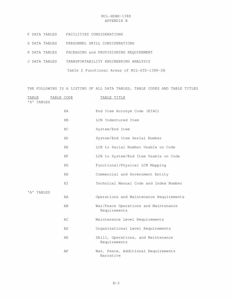
APPENDIX BMIL-HDBK-1388
B-3
F DATA TABLES FACILITIES CONSIDERATIONS
G DATA TABLES PERSONNEL SKILL CONSIDERATIONS
H DATA TABLES PACKAGING and PROVISIONING REQUIREMENT
J DATA TABLES TRANSPORTABILITY ENGINEERING ANALYSIS
Table 2 Functional Areas of MIL-STD-1388-2B
THE FOLLOWING IS A LISTING OF ALL DATA TABLES, TABLE CODES AND TABLE TITLES
TABLE TABLE CODE TABLE TITLE"X" TABLES
XA End Item Acronym Code (EIAC)
XB LCN Indentured Item
XC System/End Item
XD System/End Item Serial Number
XE LCN to Serial Number Usable on Code XF LCN to System/End Item Usable on Code
XG Functional/Physical LCN Mapping
XH Commercial and Government Entity
XI Technical Manual Code and Index Number
"A" TABLES AA Operations and Maintenance Requirements AB War/Peace Operations and Maintenance Requirements
AC Maintenance Level Requirements
AD Organizational Level Requirements
AE Skill, Operations, and Maintenance Requirements AF War, Peace, Additional Requirements Narrative
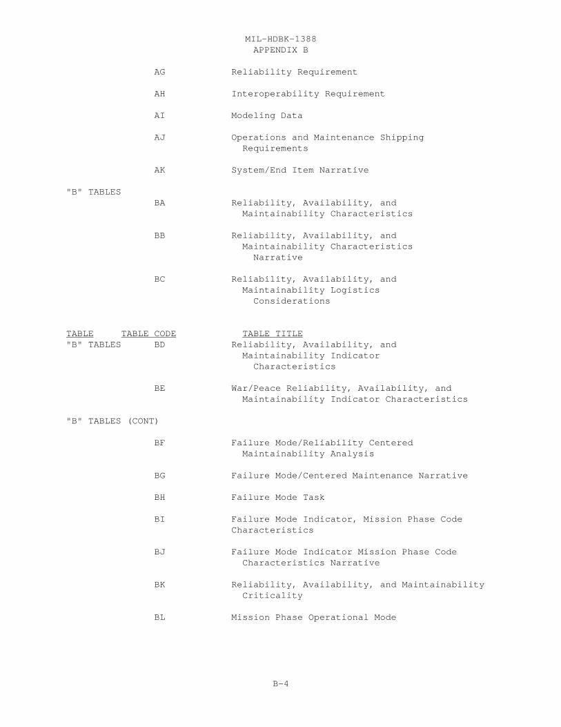
APPENDIX BMIL-HDBK-1388
B-4
AG Reliability Requirement
AH Interoperability Requirement
AI Modeling Data
AJ Operations and Maintenance Shipping Requirements
AK System/End Item Narrative "B" TABLES BA Reliability, Availability, and Maintainability Characteristics BB Reliability, Availability, and Maintainability Characteristics Narrative
BC Reliability, Availability, and Maintainability Logistics Considerations
TABLE TABLE CODE TABLE TITLE"B" TABLES BD Reliability, Availability, and Maintainability Indicator Characteristics
BE War/Peace Reliability, Availability, and Maintainability Indicator Characteristics
"B" TABLES (CONT)
BF Failure Mode/Reliability Centered Maintainability Analysis
BG Failure Mode/Centered Maintenance Narrative
BH Failure Mode Task
BI Failure Mode Indicator, Mission Phase Code Characteristics BJ Failure Mode Indicator Mission Phase Code Characteristics Narrative BK Reliability, Availability, and Maintainability Criticality
BL Mission Phase Operational Mode
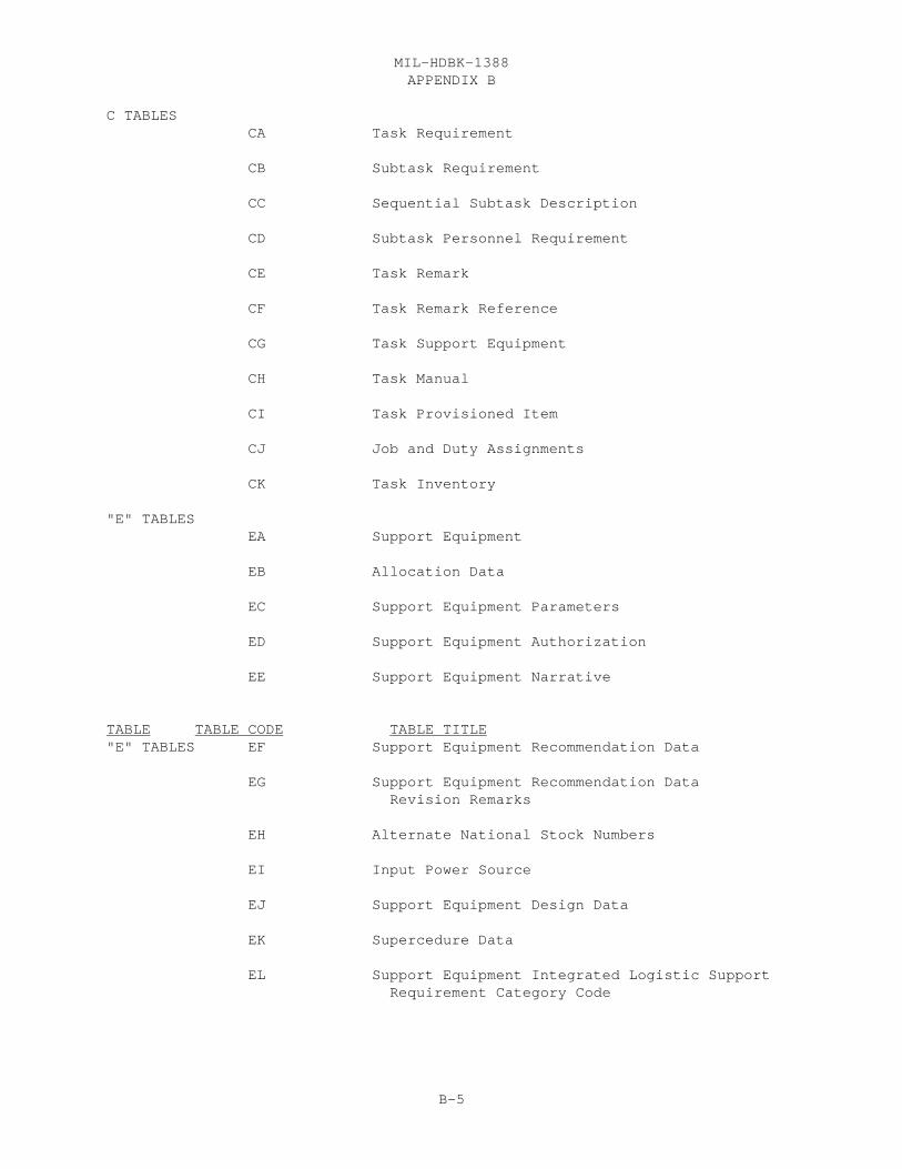
APPENDIX BMIL-HDBK-1388
B-5
C TABLES CA Task Requirement
CB Subtask Requirement
CC Sequential Subtask Description
CD Subtask Personnel Requirement
CE Task Remark
CF Task Remark Reference
CG Task Support Equipment
CH Task Manual
CI Task Provisioned Item
CJ Job and Duty Assignments
CK Task Inventory
"E" TABLES EA Support Equipment
EB Allocation Data
EC Support Equipment Parameters
ED Support Equipment Authorization
EE Support Equipment Narrative
TABLE TABLE CODE TABLE TITLE"E" TABLES EF Support Equipment Recommendation Data
EG Support Equipment Recommendation Data Revision Remarks
EH Alternate National Stock Numbers
EI Input Power Source
EJ Support Equipment Design Data
EK Supercedure Data
EL Support Equipment Integrated Logistic Support Requirement Category Code

APPENDIX BMIL-HDBK-1388
B-6
EM System Equipment
"U" TABLES UA Article Requiring Support/Unit Under Test
UB Unit Under Test Support Equipment
UC Operational Test Program
UD Unit Under Test Support Equipment Operational Test Program
UE Test Program Instruction
UF Unit Under Test Explanation
UG Unit Under Test Parameter Group
UH Unit Under Test Fault Isolated Replaceable Unit
UI Adapter-Interconnector Device
UJ Unit Under Test Support Equipment Adapter- Interconnector Device
UK Automatic Test Equipment Test Station
UL Unit Under Test Support Equipment Automatic Test Equipment
UM Support Equipment Item Unit Under Test
UN Support Equipment Unit Under Test Parameter Group
"H" TABLES HA Item Identification
HB Additional Reference Number
HC Contractor Technical Information Code CAGE
HD Unit of Issue Price
TABLE TABLE CODE TABLE TITLE"H" TABLES HE Unit of Measure Price
HF Item Packaging Requirement
HG Part Application Provisioning
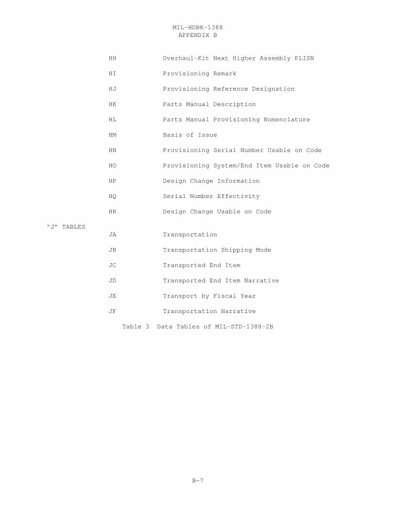
APPENDIX BMIL-HDBK-1388
B-7
HH Overhaul-Kit Next Higher Assembly PLISN
HI Provisioning Remark
HJ Provisioning Reference Designation
HK Parts Manual Description
HL Parts Manual Provisioning Nomenclature
HM Basis of Issue
HN Provisioning Serial Number Usable on Code
HO Provisioning System/End Item Usable on Code
HP Design Change Information HQ Serial Number Effectivity
HR Design Change Usable on Code
"J" TABLES JA Transportation
JB Transportation Shipping Mode JC Transported End Item
JD Transported End Item Narrative JE Transport by Fiscal Year
JF Transportation Narrative
Table 3 Data Tables of MIL-STD-1388-2B
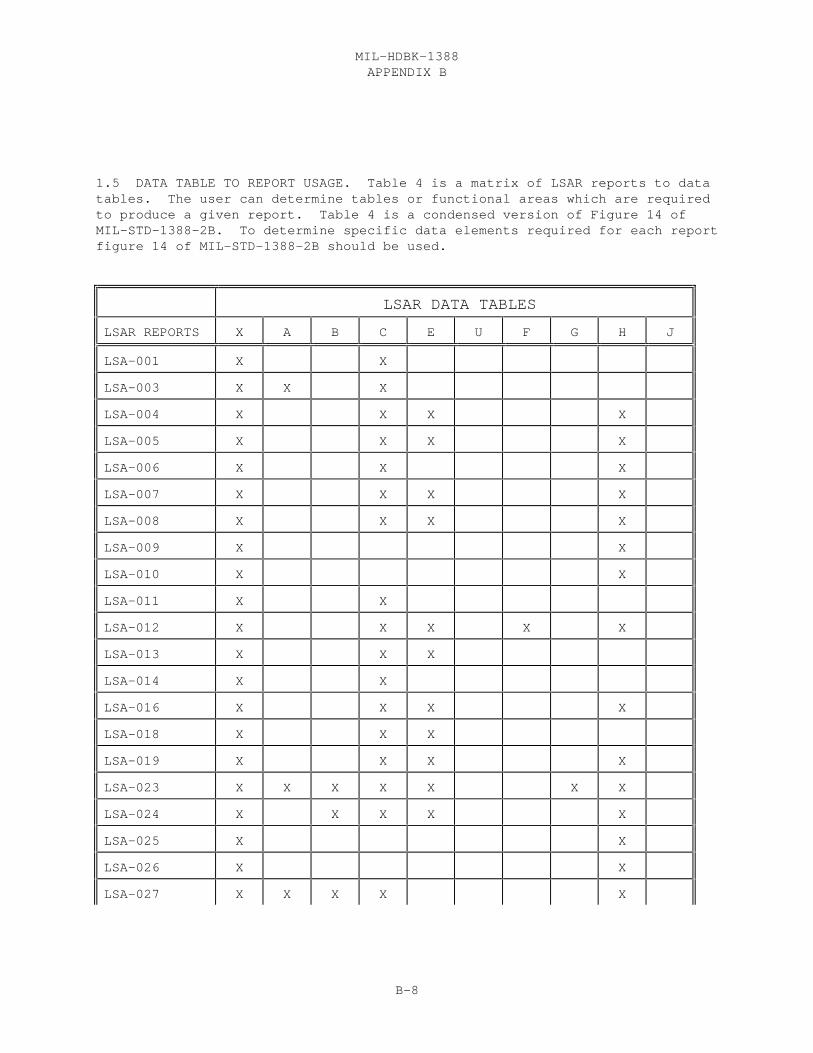
APPENDIX BMIL-HDBK-1388
B-8
1.5 DATA TABLE TO REPORT USAGE. Table 4 is a matrix of LSAR reports to datatables. The user can determine tables or functional areas which are requiredto produce a given report. Table 4 is a condensed version of Figure 14 ofMIL-STD-1388-2B. To determine specific data elements required for each reportfigure 14 of MIL-STD-1388-2B should be used.
LSAR DATA TABLES
LSAR REPORTS X A B C E U F G H J
LSA-001 X X
LSA-003 X X X
LSA-004 X X X X
LSA-005 X X X X
LSA-006 X X X
LSA-007 X X X X
LSA-008 X X X X
LSA-009 X X
LSA-010 X X
LSA-011 X X
LSA-012 X X X X X
LSA-013 X X X
LSA-014 X X
LSA-016 X X X X
LSA-018 X X X
LSA-019 X X X X
LSA-023 X X X X X X X
LSA-024 X X X X X
LSA-025 X X
LSA-026 X X
LSA-027 X X X X X
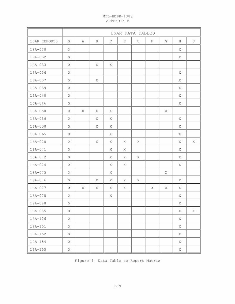
APPENDIX BMIL-HDBK-1388
B-9
LSAR DATA TABLES
LSAR REPORTS X A B C E U F G H J
LSA-030 X X
LSA-032 X X
LSA-033 X X X
LSA-036 X X
LSA-037 X X X
LSA-039 X X
LSA-040 X X
LSA-046 X X
LSA-050 X X X X X
LSA-056 X X X X
LSA-058 X X X X
LSA-065 X X X
LSA-070 X X X X X X X
LSA-071 X X X X
LSA-072 X X X X X
LSA-074 X X X X
LSA-075 X X X
LSA-076 X X X X X X
LSA-077 X X X X X X X X
LSA-078 X X X
LSA-080 X X
LSA-085 X X X
LSA-126 X X
LSA-151 X X
LSA-152 X X
LSA-154 X X
LSA-155 X X
Figure 4 Data Table to Report Matrix

APPENDIX BMIL-HDBK-1388
B-10

APPENDIX CMIL-HDBK-1388
C-1
Appendix CPROVISIONING
1. INTRODUCTION
1.1 PURPOSE. This appendix is designed to be used as a proceduralsupplement to MIL-STD-1388-2B. Three report processes that can be generatedby an Logistic Support Analysis Record (LSAR) Automated Data Processing (ADP)system directly result in functional provisioning related products. A basicunderstanding of the functional/system requirements are needed, in order toproperly code the LSAR and prepare the report selection cards to produce thesereports. The term Parts Master File (PMF) is a term used to describe theprovisioning related LSAR data, most of which is stored in the H data tables.The term LCN Master File will be used to describe all other data in the LSAR.
1.2 PRODUCT REPORTS AND THEIR INTERRELATIONSHIP.
a. The product reports, described in this guide are the MaintenanceAllocation Chart (MAC), Provisioning Technical Documentation (PTD), and RepairParts and Special Tools List (RPSTL).
(1) The MAC identifies the maintenance task functions andassociated maintenance man-hours, maintenance level allocations, tool and testequipment requirements, and other pertinent information. The MAC is produceddirectly from the LSA-004, Maintenance Allocation Chart Summary. The MAC willappear as appendix B to organizational level maintenance manuals. While theMAC is an Army-oriented summary, the Air Force use the LSA-023, MaintenancePlan Summary, and the Navy/Marine Corps uses the LSA-024, Maintenance Plan, asthe primary planning, analysis and review tools for maintenance requirements.
(2) Provisioning Technical Documentation (PTD) is used by therequiring authority for the identification selection and determination ofinitial requirements and cataloging of support items to be procured throughthe provisioning process. The various types of provisioning lists areautomatically produced using the LSA-036 report. Each service uses the LSA-036 summary for receipt of PTD as inputs to their in-house provisioning ADPsystem. Accompanying the PTD is the LSA-151, Provisioning Parts List Index(PPLI).
(3) The RPSTL or illustrated parts breakout manual contains listsof repair parts and special tools and illustrations of the parts and toolspeculiar to the end item. The RPSTL manual format includes a table ofcontents; a tabular listing of authorized spare/repair parts; a listing ofspecial tools and support equipment; illustrations that show all spare/repairparts and special tools and support equipment; and, part number/National StockNumber (NSN) to figure and item numbers indexes. The listings and indexes areproduced directly from the LSA-030, Indenture Parts List. In addition theparts manual listings, the LSAR produces the listing of variousauthorization/ancillary equipment requirements required for the operatorsmanual. These listings are the basic issue items, component of end items listitems, additional authorization list items, and expendable/durable suppliesand materials list items provided through the LSA-040, Authorization List

APPENDIX CMIL-HDBK-1388
C-2
Items Summary.
b. The MAC is a reflection of the maintenance concept. The FunctionalGroup Code (FGC) sequence of the MAC will dictate the sequence of entries inthe narrative technical manual and RPSTL. This maintenance conceptestablishes the basic guidelines under which a materiel system is to bemaintained and repaired. The MAC evolves from the maintenance concept that isdocumented in the LSAR, i.e., CA data table, during the task analysis process. The support item requirements portion of the task analysis, i.e., CG Table,serves as a baseline for determination of the Source, Maintenance andRecoverability Code (SMR). The third position of the SMR code providesauthorization for requisition and stockage of an item. The SMR code isprovided to the user in the field in the RPSTL or -P (parts) manual. The SMRcode and other PTD, i.e., Replacement Task distribution, Repair Cycle Time,Maintenance Task Distribution, and Maintenance Replacement Rates (MRR) areused for determination of initial spares and repair requirements.
c. MRR can be determined by summing the products of the Task Frequency(CA table) times the Quantity per Task (CI Table) for all tasks using theparticular Reference Number within a given component of LSA candidate. Thiscoding must be in consonance with the task analysis documentation, so theprovisioning requirement computations are performed in accordance with themaintenance concept, or MAC, and the support item authorization or RPSTL. Support items that are determined by the task analysis as necessary to beprocured and stocked, but aren’t currently in the Federal Supply System, mustbe cataloged and have NSNs assigned. These NSNs are also reflected in theRPSTL.
d. The MAC and other service maintenance plans are produced from datacontained in both the LCN and PMFs. All other provisioning oriented summariesare produced exclusively from the PMF. The PMF stores data using primarilythe CAGE and Reference Number. Multiple application of an item is stored byLCN/ALC/UOC/LCN TYPE.
e. Notice 4 to MIL-STD-1388-1A, 21 Jan 93, Logistic Support Analysis,incorporated the provisioning requirements previously contained inMIL-STD-1561B, 17 Mar 84, Provisioning Procedures, Uniform Department ofDefense. Most references made to -1A in this document are requirementspreviously contained in -1561B.
f. In order to review/validate the data and file structure to producethese product reports, a discussion of various interrelated LSAR reviewreports will also be conducted, such as the LSA-032, Defense LogisticsInformation System (DLIS) Submittals; LSA-080, Bill of Materials; LSA-151,Provisioning Parts List Index (PPLI); LSA-152, PLISN Assignment/Reassignment,also the LSA-016, and the Preliminary Maintenance Allocation Chart (PMAC).

APPENDIX CMIL-HDBK-1388
C-3
2. CODING REQUIREMENTS AND REPORTSELECTION LOGIC EXCEPTION FOR
PROVISIONING REPORTS
2.1 ASSIGNMENT OF THE LCN.
a. The LCN assignment techniques described in appendix C ofMIL-STD-1388-2B, are appropriate for developing the LSAR database forprovisioning purposes. It is important to emphasize that LCNs are assigned inhardware generation breakdown sequence and not by Work Unit Code/TechnicalManual (WUC/TM) Functional Group Code (FGC) or work breakdown structure codes.
b. When LCNs are assigned sequentially, the LCN-IC must be manuallyentered in the LSAR, XB table, before PCCN, PLISNs, ICs and NHA PLISNs can beautomatically assigned. The LCN-IC must begin against the first item within aPCCN.
2.2 UOC ASSIGNMENT.
a. The UOC is a key data element used to identify themodel/configuration relationship of each LCN comprising a system/equipment,and to control these relationships for LSAR report generation. EachSeparately Provisioned End Item record, in the XC table, will contain a UOC. The part application records in the HG table are linked to the applicable UOCthrough the HO table. A part application may be tied to multiple UOCs byhaving multiple HO records but may have only one PCCN. The MAC data is tiedto the UOC through the XF table. The HO and XF tables eliminate theduplication of data merely because an item has application to multipleconfigurations/models.
b. Multiple UOCs should not be assigned to the same LCN when theapplication related information such as SMR, quantity data or analysis data. This situation dictates input of additional relational table rows using theALC to show different data for the same LCN and a different UOC.
2.3 ALTERNATE LCN ASSIGNMENT
a. The LSA-004, LSA-152, and the LSA-030 can be selected without regardfor the ALC. In fact, ALC selection is not an option on the LSA-152 report. The LSA-030 selects on TM code disregarding LCN/ALC assignments. Because ofthis, ALC should be used to document alternate vendor or model (UOC) items,but under no circumstances should be used to document an alternate end item(PCCN). When documenting alternate maintenance concepts/configurations, whichultimately do not represent the final concept/hardware configuration,documentation and selection of the MAC by the TM Code will allow these itemsto be screened out of the selection process.
b. ALC coded assemblies, subassemblies, of piece parts are sequencedimmediately following the breakdown of the basic item for which it isinterchangeable when using the LSA-152, PLISN Assignment/Reassignment routine.This is applicable whether the alternate item is from an alternate model, i.e.
APPENDIX CMIL-HDBK-1388
C-4
having a different assigned UOC, or is an alternate vendor component. Caremust therefore be exercised to assign all the alternate items components/pieceparts the same ALC, and to ensure that no break or gap in either the LCNstructure or IC exist. A break in the items’s breakdown structure, i.e., amissing indenture level, will not create an error condition, but will causethe alternate item to appear as part of the basic item.(See Figure 1). TheConnector, Plug is different on each configuration. Since there is no Bindenture documented for the "01" ALC structure, the "C" indenture "01" ALCconnector plug is documented as part of the basic, "00", system and will haveit’s PLISN assigned in this manner. To avoid this situation, the "B"indenture Power Supply should be repeated, completing the Alternate structure(figure 2). Review the LSA-80, Bill of Materials List to validate properstructure of ALC assemblies.
c. Specific guidance for documentation of alternate assemblies in theLSAR should be received from the requiring authority, since this documentationmay lead to "doubling" the spares requirements when requirements computationsare performed.
d. When multiple alternate items are to be documented, the first to besequenced will be the alternate with the lower assigned ALC, i.e., an itemwith an ALC "A" will appear before an item with an ALC "B", when both have thesame LCN. When a break occurs in the structure of an ALC documented item orwhen another value of ALC is documented, these items will again besequence/inserted within the basic system LCN ("00" ALC) structure. This willpreclude the documenting of an alternate sub assembly within an alternateassembly, since instead of sequencing the alternate subassembly within thealternate assembly, it would insert the item back to the basic system (SEEFigure 3.) In this example there are two applicable circuit cards for thealternate "01" Controller Assembly. The "02" circuit card will not beassigned a PLISN as if it were under the Controller assembly, but rather itwould be documented as part of the "00" controller assembly. To document theabove situation, it is necessary to assign the alternate subassembly the nextavailable LCN following the breakdown of the subassembly that it replaces andcode the alternate subassembly with the same ALC as the alternate assembly. (SEE figure 4.)
2.4 FGC (WUC/TM FGC) VERSUS LCN ASSIGNMENT
a. The FGC assigned to the XB table is displayed as the Group Number onthe MAC report, while the FGC used in the PMF (HK table) is not displayed inthe formal RPSTL report portion of the summary. However, it is the primesequencing key for the report generation. The matching FGC between the MACand RPSTL is not necessarily contained in the Parts File for the identicalLCN/ALC combination. The matched FGC is a throughput on the "D" section cards(FGC header) when the RPSTL report is generated. Specific guidance on FGCassignment is normally provided by the requiring authority (publicationscommunity), since a standardized method of FGC assignment for commodity typesof components/items is normally established. These standardized assignmentsmake it easier for the user in the field to cross-reference between differentTMs of equipment maintained by that organization. For instance, engines mayalways be documented under an FGC of "04" across all Army helicopter types.

APPENDIX CMIL-HDBK-1388
C-5
Figure 1. PLISN Assignment Where Alternate Assembly Missing B IndentureFigure 2. PLISN Assignment With Complete ALC Structure
APPENDIX CMIL-HDBK-1388
C-6
Figure 3. PLISN Assignment Of Alternate Subassemblies On Alternate AssembliesWith Different ALCsFigure 4. PLISN Assignment Of Alternate Subassemblies On Alternate AssembliesWith The Same ALC

APPENDIX CMIL-HDBK-1388
C-7
b. There are conditions when the FGC, that is documented in the LCNMaster File, must be different from the code contained in the PMF for anidentical LCN. Since the FGC is used for sequencing publications, it may beassigned in a manner to facilitate this development, rather than be in anunadulterated complete topdown generation breakdown, such as what is used forLCN/PLISN assignment. An example of such a situation would be a higher levelRPSTL illustration, which depicts only one indenture of lower level parts. Some of these parts may be reparable with lower indenture(s) ofcomponents/piece parts beneath them. These reparable items’ breakdown wouldbe documented in another illustration, or possibly, in another manualaltogether. When documenting these items by means of the LCN/PLISN, allreparable items must be broken down completely to piece-part level beforebeginning another indentured components/piece parts to the proper location ofthese items in the RPSTL by assigning an FGC that is greater than the FGCsassigned to all the items depicted on the higher level illustration.
c. When an alternate vendor assembly is to be documented in the MAC andRPSTL, a unique FGC should be assigned to this item even though the item maybe contained in the LSAR under an identical LCN distinguished by ALC. Anexample of FGC versus LCN assignment to the Parts File is provided atfigure 5. A comparison of file sequencing, based upon LCN/ALC with both PLISNand WUC/TM FGC sequence, is provided at figure 6.
d. Figure 7 illustrates a technique for assigning FGCs to both the LCN(XB) and PMF (HG). Notice that a distinct FGC is assigned to each reparable(illustrated) item in the LCN file. Each of these items will then appear as aseparately, called-out item on the MAC. When the FGC is then assigned to thePMF, the same FGC that is assigned to the assembly (illustration) level isused for each item (reparable and nonreparable) that comprises the assembly.
e. Using this technique, the Item Number then becomes the primarysequencing criteria within an illustration. The LCN Master File and PMF FGCswill not match on LCN, but will "track" based on LCN and subordinate LCNrelationships from the LCN and Parts files, respectively.
f. This technique will work for most illustrations. A RPSTLillustration review should be made when assigning FGCs to the PMF, since it ispossible to illustrate smaller subassemblies completely within a higherassembly illustration. This is documented in the RPSTL data by using the TMIC. Standard practice calls for subassembly parts, documented in theillustration of an assembly, to be TM Indentured by "2". This will causethese parts to appear in the RPSTL with two leading periods (.) before theitem names. If the FGC and illustration instructions provided by therequiring authority deviate from the actual hardware generation breakdown(engineering drawings) by requiring a more functional oriented approach, theLCN and subordinate LCN relationship between the files may not be strictlymaintained with the assigned FGCs.
2.5 TM CODE
a. The TM Code can be assigned to the CH table (LCN Master File) andthe HJ, HK and HL tables (Parts Master File). Use of the TM Code in the LCN

APPENDIX CMIL-HDBK-1388
C-8
Figure 5. LCN Versus FGC Assignment

APPENDIX CMIL-HDBK-1388
C-9
SEQUENCING ON LCN/ALC - PLISN - FGC (LCN STRUCTURE 12222)
LCN SORT
LCN ALC NOTE FGC PLISN 1. A AAAA 2. A A 1 AAAB 3. A01 001 AAAJ 4. A01AA 0101 AAAK 5. A01AA A 2 0101 AAAL 6. A01AB 0102 AAAM 7. A01AC 0103 AAAN 8. A02 002 AAAP 9. A02 A 1 002 AAAZ 10. A02AA 0200 AAAQ 11. A02AA A 1 0201 AAA1 12. A02AB 0200 AAAR 13. A02AB A 1 0202 AAA2 14. A02AC 0200 AAAS 15. A02AC A 1 0201 AAA3 16. A02AC B 2 0200 AAAV 17. A02AC01 02300 AAAT 18. A02AC01 A 1 02301 AAA4 19. A02AC01 B 2 02302 AAAW 20. A02AC02 02300 AAAU 21. A02AC02 A 1 02301 AAA5 22. A02AC02 B 2 02302 AAAX 23. A03 003 AAAY
PLISN SORT 1. A AAAA 2. A A 1 AAAB 3. A01 001 AAAJ 4. A01AA 0101 AAAK 5. A01AA A 2 0101 AAAL 6. A01AB 0102 AAAM 7. A01AC 0103 AAAN 8. A02 002 AAAP 9. A02AA 0200 AAAQ 10. A02AB 0200 AAAR 11. A02AC 0200 AAAS 12. A02AC01 02300 AAAT 13. A02AC02 02300 AAAU 14. A02AC B 2 0200 AAAV
1. ALCS REPRESENTING COMPONENTS TO ALT MODEL ITEM
2. ALCS REPRESENTING ALT VENDOR COMPONENT(S) (LINKED TOGETHER IN PLISN ASSIGNMENT BY LCN STRUCTURE)
Figure 6. LCN - PLISN - FGC File Sort Example.
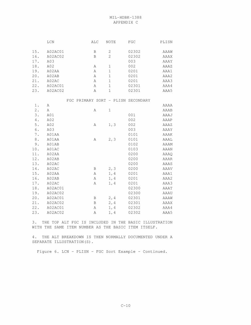
APPENDIX CMIL-HDBK-1388
C-10
LCN ALC NOTE FGC PLISN
15. A02AC01 B 2 02302 AAAW 16. A02AC02 B 2 02302 AAAX 17. A03 003 AAAY 18. A02 A 1 002 AAAZ 19. A02AA A 1 0201 AAA1 20. A02AB A 1 0201 AAA2 21. A02AC A 1 0201 AAA3 22. A02AC01 A 1 02301 AAA4 23. A02AC02 A 1 02301 AAA5
FGC PRIMARY SORT - PLISN SECONDARY 1. A AAAA 2. A A 1 AAAB 3. A01 001 AAAJ 4. A02 002 AAAP 5. A02 A 1,3 002 AAAZ 6. A03 003 AAAY 7. A01AA 0101 AAAK 8. A01AA A 2,3 0101 AAAL 9. A01AB 0102 AAAM 10. A01AC 0103 AAAN 11. A02AA 0200 AAAQ 12. A02AB 0200 AAAR 13. A02AC 0200 AAAS 14. A02AC B 2,3 0200 AAAV 15. A02AA A 1,4 0201 AAA1 16. A02AB A 1,4 0201 AAA2 17. A02AC A 1,4 0201 AAA3 18. A02AC01 02300 AAAT 19. A02AC02 02300 AAAU 20. A02AC01 B 2,4 02301 AAAW 21. A02AC02 B 2,4 02301 AAAX 22. A02AC01 A 1,4 02302 AAA4 23. A02AC02 A 1,4 02302 AAA5
3. THE TOP ALT FGC IS INCLUDED IN THE BASIC ILLUSTRATION WITH THE SAME ITEM NUMBER AS THE BASIC ITEM ITSELF.
4. THE ALT BREAKDOWN IS THEN NORMALLY DOCUMENTED UNDER A SEPARATE ILLUSTRATION(S).
Figure 6. LCN - PLISN - FGC Sort Example - Continued.

APPENDIX CMIL-HDBK-1388
C-11
Figure 7. FGC Assignment In The LSAR Data Tables

APPENDIX CMIL-HDBK-1388
C-12
file is optional to generate a proof MAC. It is used to distinguish specifictasks within an LSA candidate, which may be applicable to two separate MACs. TM Code selection of the MAC can be significant when a system level MAC reportis required, which needs to document only the removal/replacement of asubordinate end item. In this case, the LCN of the end item would have theReplace task function entered with the TM Code of the system and the othermaintenance functions, i.e., repair, inspect, fault locate, entered with theTM Code for the subordinate end item. This, of course, is applicable whenseparate organizational (-20) manuals are to be developed for the systemitself and the end item within the system.
b. Use and assignment of the TM Code within the LCN file is much lessrestrictive than use in the Parts File. The preparing activity may control TMcodes assigned to the LCN file without worrying about interfacing with agovernment ADP system. If the preparer does opt to utilize the TM Code todesignate tasks to be contained in the proof MAC, he must assign the same TMcode throughout the file to all CH Task Codes depicted in the MAC beingdeveloped. Then, LCN will no longer become the primary selection item for theLSA-004 report.
c. The TM Code entered in the PMF is assigned by the requiringauthority. The TM code represents a TM Designation series for an RPSTLe.g., -20P, -34P, of the same TM series (TM9-2350-300-XXP)). The TM Code mustcorrespond to a TM Code to TM Designation Index maintained within theCommodity Command Standard System (CCSS). The TM Code is a provisioning KeyData Element to all the other RPSTL data, meaning that without the TM Code inthe PMF, the associated RPSTL data, i.e. Figure Number, Item Number TM IC,will not be displayed on the LSA-036 report and submitted to the requiringauthority. The proof RPSTL report selection keys to TM Code for reportgeneration.
2.6 LCN-IC AND IC.
a. There are two types of Indenture Codes (ICs) documented in the LSAR,which depict either a total system or end item relationship.
(1) The LCN-IC is used to depict a relationship of an item’sapplication to the entire LSAR system based upon the assigned LCN. The LCN-ICis only assigned when a sequential LCN assignment method is utilized, wherethe indenture level cannot be determined by LCN alone.
(2) The IC is used to identify the hardware breakdown of an item’sapplication to its provisioned end item. The IC can be either automaticallyassigned, based upon the LCN structure logic using a classical LCN assignmentmethod, or by LCN-IC and the relationship of the provisioned end item to thetotal LSAR system.
b. The IC can be automatically assigned to the PMF (HG Table) using theLSA-152, PLISN Assignment/Reassignment process.
(1) When a sequential LCN assignment method is utilized, the LCN-ICmust be entered in the XB table. The LCN-IC entered should represent the

APPENDIX CMIL-HDBK-1388
C-13
indenture in relation to the total system (LCN), not the IC of the provisionedend item, if the user intends to utilize the LSA-152 system to assign PLISNs. For example, suppose the LSAR is developed for a main battle tank, and therequiring authority decides to manage the tank engine, which has a "C"indenture to the tank, as a separately provisioned end item, i.e. under adifferent PCCN. The engine will be documented in the LSAR as follows; arecord will be placed in the XC table denoting the item is a separatelyprovisioned end item, the LCN-IC would have been developed in the XB table asa "C", and the item will be in the HG table with two records in the HO tableshowing its relationship to the tank and to itself. (Note: Only subordinateend items are allowed to have multiple HO records mapped to multiple PCCNs inXC.) When the PLISN assignment routine is run on the tank, the ADP systemfinds the engines relationship to the tank from the LCN-IC (table XB), andassigns a "C" to the HG table IC (Figure 8).
(2) At the next indenture below the engine are the engine block andcarburetor assembly. When the PLISN assignment is run for the engine, the ADPsystem will compare the engine block and carburetor assembly LCN-IC with thatof the engine and assign the proper IC. Figure 9 shows this example. Sincethe ADP system will only build HO records to one PCCN for each partapplication record in HG, unless the item is a subordinate end items in whichcase it can have two, the ADP system will be able to determine which "C"indenture items are related to the engine and which are related to the turret. Note the IC of the Engine is only output "A" on the LSA-152, and LSA-036 butnot updated in the HG table. This situation only arises for subordinateseparately provisioned end items.
(3) Manual IC, PCCN/PLISN, and NHA PLISN assignment can be reviewedby using the LSA-080 report.
2.7 PROVISIONING CONTRACT CONTROL NUMBER (PCCN) RELATIONSHIPS.
a. The PCCN is a manditory selection on the LSA-152 and LSA-036 report,and is an optional selection LSA-032, LSA-080, LSA-126, and LSA-151 reports. When the provisioning data is entered, the ADP system should build HO recordsto tie the HG part application data back to their end items located in the XCtable. A part application can have several Usable On Codes (UOCs) but canonly have one End Item or PCCN. In other words, a part application (HGrecord) may have several HO records tying it back to several XC records, butall of the XC records must have the same PCCN. In the example below the LCNLEAA05AE is tied to UOC’s CE1 and CD2 but both have the PCCN GLH850.
b. There can be only one LCN assigned to each PCCN in the XC table, butthere may be multiple UOCs. See the example below. Both of the XC recordshave the same LCN, LEAA05, the same PCCN, GLH850, but different UOCs CE1 andCD2. The reason this is established in this manner is to avoid duplication ofcommon parts. All common parts will be documented under the basic ALC item,and only parts peculiar to the alterant assembly will be documented under thealternate assembly. When the PCCN, GLH850, is selected parts under both UOCsCE1 and CD2 will be selected. See section 2.2 and 2.3 for more information onUOC and ALC assignment.

APPENDIX CMIL-HDBK-1388
C-14
1 2 3 4 5 6 7 8 9 ----+----0----+----0----+----0----+----0----+----0----+----0----+----0----+----0----+----0----+----+XC T850 LEAA05 00PCE1GLH850LH-850A/LHTEC850 AAAA 0001 XC T850 LEAA05 01PCD2GLH850LH-850A/LHTEC850 AAAB 0001 HO T850 P645472118539 LEAA05AA 00LEAA05 00HO T850 P645472118539A LEAA05AA 01LEAA05 01HO T850 P68524DCT7900P4A2 LEAA05AA00 01LEAA05 01HO T850 P68524DCT7900P4A2 LEAA05AA00 00LEAA05 00HO T850 P645472123254 LEAA05AC 00LEAA05 00HO T850 P645472123497 LEAA05AC00 00LEAA05 00HO T850 P645472123497A LEAA05AC00 01LEAA05 00HO T850 P64547805986 LEAA05AE 01LEAA05 01HO T850 P64547805986 LEAA05AE 01LEAA05 00
HG 64547805986 T850 LEAA05AE 01PA027 0001 C Y Y B...
2.8 SUPPRESSION INDICATOR CODE (SIC). The SIC was used in the -2Asoftware to suppress the assignment of PLISNs to subordinate end items. The -2B LSAR ADP systems suppress the subordinate end items by only allowing apart application to be tied to one PCCN in the HO table, with the exception ofsubordinate end items themselves which will have two. The SIC can still beused to stop PLISN assignment at any desired location.

APPENDIX CMIL-HDBK-1388
C-15
Figure 8. PLISN Assignment With Sequential LCN Structure.Figure 9. PLISN Assignment of Subordinate End Items With Sequential LCNStructure.

APPENDIX CMIL-HDBK-1388
C-16
3. MAINTENANCE ALLOCATION CHART (MAC)
3.1 PURPOSE OF THE MAC.
a. The MAC is contained in appendix B of the Organizational LevelMaintenance Manual (-20). It depicts maintenance authorizations and averagemaintenance times by function and maintenance level. It also contains areference to peculiar tools and test equipment required against eachmaintenance function. The MAC consists of four sections developed inaccordance with (IAW) MIL-M-63038 (TM). The proof LSA-004 report is capableof producing Sections II-IV.
(1) Section I, Introduction. This is developed IAW figure 20 ofMIL-M-63038(TM).
(2) Section II, MAC. The proof LSA-004 report is formatted accordingto the requirements of this section.
(3) Section III, Tool and Test Equipment Requirements. The proofLSA-004 report fulfills the requirements to produce this section.
(4) Section IV, Remarks. The proof LSA-004 report fulfills therequirements to produce this section.
b. The draft MAC report contains all the maintenance levels andfunctions, as they are defined under the Task Code data element definition inMIL-STD-1388-2B. Man-hours in the report are rounded to the nearest hundredthof an hour. When a task is documented against a particular item, but thecomputation of mean man-hours for the function is not rounded to 1/100 of anhour, the man-hour field of the draft MAC will be filled with asterisks;however, on the proof MAC, a value of 1/10 of an hour will be displayed. Ifthe man-hours are zero or are not entered against a proof MAC qualified task,asterisks will appear in the Man-hour column. When the LSA-020 reportcontains a tool Reference Number, which is not matched with a PMF ReferenceNumber, SCC combination, asterisks will appear in the NSN column. The proofMAC contains the maintenance functions, as defined in MIL-M-63038(TM):
(1) Access, Disassemble/Assemble and Fault Locate times are includedas part of the repair time.
(2) Remove and Install times are included as part of the Remove/Install time.
(3) Lubricate times are included as part of service times.
(4) End of Runway Inspection is included as part of Inspect time.
(5) Mission Profile Change, Package/Unpackage, Preserve, Operate,Transport, and Transportation Preparation are not included on the proof MAC.
c. An aviation MAC formatted IAW figure 21 of MIL-M-63038(TM)using the Operations/Maintenance (O/M) levels Aviation Unit Maintenance (AVUM)

APPENDIX CMIL-HDBK-1388
C-17
or "O"; Aviation Intermediate Maintenance (AVIM) or "F"; and, Depot or"D" can also be produced from the LSAR.
3.2 MAC MAN-HOUR COMPUTATIONS.
a. For each maintenance level determined by the O/M Level subfield of theTask Code, the Mean Man-hours is calculated for all tasks with the same taskfunction or consolidated task functions as follows:
N � (TFi) (M-Hi) i=1 M-Hm = ______________________
N � TFi i=1
M-Hm = Mean man-hours M-Hi = Total man-hours for task i (calculated by summing the man-hours for each SSC of Task i) TFi = Task Frequency for task i N = Total number of tasks performed
b. For each unique O/M level entry within an LCN, a separate maintenancefunction row is required. When the Task Frequency value for the only taskfunction documented against an LSA candidate is zero, then the total man-hoursfor that task will be displayed in the Man-hour column of the MAC. Documentation of a task in this manner may be necessary when the only repairtask against a higher level assembly consists in the removal/replacement of alower indentured assembly. The man-hours should be documented against bothassembly (REPAIR task function) and the subassembly (REPLACE task function),but in order to preclude "double counting" of man-hours to perform the sametask under the assembly and subassembly, i.e., the LSA-001 report, a zero taskfrequency for the higher assembly with the repair task function is enteredinto the LSAR.
c. By reviewing the format of the MAC, it should become obvious the onlyway to properly allocate maintenance man-hours against a particular "GROUP" orWUC/TM FGC, is to document those task codes pertaining to an item against theitem’s LCN. It should also be noted that a Replace function is applicable toremoval/replacement of the LSA candidate itself, and not of a lower indenturedspare/repair part.
d. It is recommended data item description (DID), DI-ILSS-81140A,Maintenance Allocation Chart (MAC), be utilized in order to ensure anacceptable MAC, derived from the LSAR, is produced and delivered by thepreparing activity.

APPENDIX CMIL-HDBK-1388
C-18
3.3 RELATIONSHIP OF THE MAC AND TOOL AND TEST EQUIPMENTREQUIREMENTS SECTIONS.
a. The MAC section is derived directly from the CA or CH task analysisdocumentation for the selected LCN range or TM Code, respectively. Whenproducing the Tool and Test Equipment Requirements section, the appropriateItem Category Codes (ICC) for these types of items must be entered on thereport selection. These items (ICCs) are matched with the CG/EA record ICCsof the qualified Tasks.
b. When producing a draft MAC, any combination of ICCs may be entered inorder to review/validate any group of support equipment or items required forthe selected Tasks; however, when the proof MAC is developed, the ICCs shouldbe limited to those categories which represent system peculiar tools andexisting or new tool kits and outfits. It should not contain common tools asseparately selected items.
c. A consolidated list of all tools/tool kits across all qualified tasksis generated (section III), and a numerical reference is assigned to thislist in ascending part number sequence. This numerical reference is thenincluded in the Tool and Test Equipment column of the MAC for every qualifiedtask in which the referenced tool is utilized. The numerical reference isdisplayed on a line across from the task function listed on the MAC. On theTool and Test Equipment Requirements section, under the Maintenance Categorycolumn, a consolidation of all maintenance levels requiring the particulartool/test equipment is displayed. This is determined by the O/M Levelssubfield of the task codes requiring the item.
d. A consolidated list of all remarks for qualified tasks is generated inSection IV. Remarks are limited to applicable Section II (or TM-FGCs) andMaintenance Functions by Remarks Reference Codes (table CF).
3.4 MAC SOURCE DATA.
a. The MAC is a reflection of the results of maintenance planning. Itdoes not provide either the analyst or the reviewer with a tool to assess theoptimization of supportability requirements for the weapon system. Byreviewing other LSAR output reports, the analyst may obtain a better pictureof the true impact the system will have on logistics resources. For example:
(1) a. The LSA-001, Annual Man-hours By Skill Specialty Code andLevel of Maintenance, will provide the analyst with a one or two-page summaryof the total O/M man-hours required to support the weapon system. This datacan be used to assess the new system impact on field/depot manpower byMilitary Occupational Specialty (MOS)/Wage Grade (WG).
b. The LSA-001 also provides the analyst with a one-line summaryof all tasks requiring a given MOS/WG. Also provided on the report are asummary of MOS skill levels required, as well as any requirement for specialtraining equipment to acquire the skill to perform the task. Review of thisreport may lead the analyst to request a detailed step-by-step task review bymeans of the LSA-015, Sequential Task Description, or a review of the E record
APPENDIX CMIL-HDBK-1388
C-19
for training material requirements.
(2) The LSA-006, Critical Maintenance Task Summary, provides theanalyst with a listing of tasks which exceed a report parameter in descendingsequence of the selected parameter values. The report may be selected againstfour categories of data: task frequency; elapsed time; man-hours; or, annualman-hours. Again, as with the LSA-001 report, tasks depicted on the LSA-006report as "high drivers" of the weapon system’s logistics requirements maybe reviewed in great detail, and on an exception basis, by requesting anLSA-015 report against those tasks that are contained in this report.
(3) The LSA-007, Support Equipment Requirements; LSA-011, Requirementfor Special Training Device; LSA-012, Requirements for Facility; and, LSA-014,Training Task List, may be used to determine, again on an exception basis,those tasks requiring greater review via the LSA-029 report, as well as thosetasks requiring additional justification.
b. The above report utilizations represents only one technique to reviewthe information that is available using the LSAR and the Joint Service LSARADP System. Ad hoc queries can also be utilized (if user’s ADP system has thecapability) as a review tool.

APPENDIX CMIL-HDBK-1388
C-20
4. PROVISIONING REQUIREMENTS
4.1 PREPARATION OF THE PMF.
a. In order to ensure the LSAR PMF is accurate and complete to performprovisioning, e.g, to generate an LSA-036 report, there are several review andanalysis reports which can be used to ascertain the file condition. These are:
(1) LSA-016, Preliminary Maintenance Allocation Chart (PMAC)
(2) LSA-027, Failure/Maintenance Rate Summary
(3) LSA-080, Bill of Materials
b. The PMAC is a more detailed depiction of the maintenance concept.
(1) The PMAC displays each LSA candidate having Task Functions "A""N" "R", "S" or "W", and computes the average man-hours for each candidate byfunction and maintenance level similar to the MAC. In addition, the PMAC canalso display a listing of all the repair parts or "Y" ICC items, which aredocumented in the LSAR for the tasks functions of Replace and Repair (othersupport items can be displayed based on ICCs). These repair parts aredisplayed by item name and reference number. A comparison is then made of allqualified tasks for the LSA candidate to determine the lowest maintenancelevel which can remove/replace the repair part. This maintenance level isalso displayed on the same line with the repair part. The analyst can thenuse this information to assign the SMR to these nonreparable items.
(2) By reviewing the task functions and associated maintenance levelson the PMAC, the SMR for the LSA candidate can also be assigned. The LSA-016report can also be used to validate the LCN/Reference Number assignmentbetween the LCN and PMF. When a particular LSA candidate is qualified fromthe LCN file for inclusion in the PMAC report, the report process will crossvia LCN and Reference Number to the PMF, in order to extract and displaycertain parts file data. If there is no match between the LCN and PMF oneither LCN or Reference Number, the PMF data will not be displayed on theLSA-016 report.
c. The LSA-027 report displays a comparison of the Failure Rate,Replacement and Repair Task Codes, and their associated Task Frequenciesagainst each LSA candidate and displays the SMR, MRR, and MRRII from the PMFto validate this critical provisioning data.
d. The LSA-080 report provides a detailed analysis of the provisioningdata contained in the PMF. The Bill of Materials Report, Part I, identifiesassembly level items, and a one indenture lower listing of the spare/repairparts that comprise the assembly. The LSA-080 report can be used to check forcompleteness of the PMF against assembly drawings and may also be useful forRPSTL data development:
(1) The report is sequenced by the assembly level reference
APPENDIX CMIL-HDBK-1388
C-21
number, so that it can track with a drawing package provided in drawing numbersequence. Basic data related to the development of a properly structured PPLis also edited.
(2) An LSA-80 report should accompany an LSA-036 report whenperforming an LSA/LSAR/Provisioning Review.
4.2 UTILIZATION OF THE AUTOMATIC PLISN ASSIGNMENT ROUTINE.
a. The LSA-152 summary assigns/reassigns provisioning related control andreference data to Table HG, PLISN, Indenture Code (IC), NHA PLISN, and TableHH, Next Higher Assembly (NHA) PLISN, based on selection parameters. Thesummary will depict the file content before and after the assignments orreassignments are made. PLISNs are assigned using the EBCDIC collatingsequence.
b. It is necessary that the LSAR be properly structured using either auniform (nonbroken) LCN structure when applying either a classical or modifiedclassical LCN assignment technique; or an LCN-IC (Table XB) assignment withoutmissing or unlinked indenture levels, when LCNs are assigned using thesequential method. Using the LSA-080 report, the analyst can review the filefor correct structure, or by using the LSA-152 report detect error conditionsin file structure.
c. The LSA-152 report consists of two parts. Part I will only be outputwhen an error in file structure is encountered, or when the PLISN assignment(with selected PLISN spacing) exceeds the limit of 9999 for the proposedassigned PMF candidates. When these occur, the error location in the file isdepicted on the report with a display of the unlinked or remaining filesegment. If an error condition does occur, the LSA-152 process will notassign any PLISNs, but will continue processing to determine whetheradditional error conditions exist in the file. Validated LSAR systems will berequired to have the capability to produce an error listing for the LSA-152report. However, the format, messages and explanation of those messages forthe error listing is vendor dependent. Part II of the report reflects theresults of the PLISN assignment/reassignment; only a Part I or a Part II willbe produced in a processing cycle.
d. The report selection for PLISN assignment occurs within a PCCN andoptionally Start and Stop LCN range. ALC is not a selection option.Alternate LCNs must be considered when assigning the basic LCN PLISNs becausealternates may have basic items as NHAs. A row in table HO creates the enditem (XC) to part application (HG) relationship. One HG row cannot be relatedto multiple PCCNs except when the item is a subordinate end item. When theitem is a subordinate end item, HO would have one row depicting the end itemrelationship (end item and item LCN-ALCs are the same), and one or more rowsshowing the relationship to the system. Having the end items located in theXC table, and the fact that no other item except a subordinate end item can belinked to more than one PCCN, makes the suppression indicator code obsolete.
e. Since there are unlimited "correct" structuring techniques using theALC, there is no system edit to detect errors in file structure when the ALC

APPENDIX CMIL-HDBK-1388
C-22
is utilized. ADP systems will detect a missing indenture level for alternateassemblies and sequence them back to the basic "00" LCN structure. Referencesection 2.3 of this document of the effects of ALC coding during PLISNassignment. ALC assignment errors can only be detected by a manual review ofthe LSA-152 or LSA-080 reports.
f. There is a wide range of options when using the PLISN assignmentroutine:
(1) NHA PLISNs and/or ICs may be assigned to the PMF, if this optionis selected on the 152 report.
a. If the file is constructed using the classical/modifiedclassical LCN assignment technique, the IC may be assigned, provided the LCNstructure exists in the XA table. Asterisk ICs may be assigned to the partsfile based on the ICC of "9" representing kit components being previouslyassigned (Table HG). An option is also available to assign a constant NHAPLISN indicator of "N" against each NHA PLISN assigned to the HH table.
b. When a sequential LCN assignment method is utilized, the LCNstructure field is left blank in the XA table, and the LCN-ICs must beentered on the XB table in order to assign NHA PLISN. The IC (Table HG)should be that of the provisioned end item, while the LCN-IC should be relatedto the system level in the LSAR.
(2) When assigning PLISNs for a subordinate end item the IC is notassigned to the HG table. For example, a separately provisioned end item atthe "C" indenture to the system (LCN-IC,Table XB) will have an IC of "A" comeout on the LSA-152, and LSA-036 reports but will keep its IC of "C" assignedunder the system end item assignment. All components to the subordinate enditem will then have their IC assigned as before. For example, a "D" indentureitem under the "C" indenture subordinate end item will have a "B" IC assignedwhen PLISN assignment is run on the "C" indenture subordinate end item. Seesection 2.6 for a more detailed explaination.
(3) PLISNs may be assigned only to items that qualify by PTDSelection Code for a specified Provisioning List (PL) or lists (Table HG).
(4) PLISNs may be assigned in either topdown (LCN) or ReferenceNumber sequence. When PLISNs are assigned in Reference Number sequence, thesystem will lock out the option to assign NHA PLISNs/ICs. Default is topdown.
(5) PLISNs may be assigned as either all alphabetic, alphanumeric,numeric, or, first position alphabetic, then second through fourth positionnumeric. Default is alphanumeric.
(6) A starting PLISN value may be specified on the report selectioncard.
(7) PLISN values of "AAAA" through "AAAHZ" may be reserved for thesystem level and separately provisioned end items (Model Reserve). If thisoption is selected, a starting model PLISN value may be specified (within the

APPENDIX CMIL-HDBK-1388
C-23
given range). If none is selected, the first model PLISN assignment will be"AAAA".
(8) PLISNs may be assigned to overlay old PLISN values establishedin the file; to overlay PLISNs and to move the old PLISN value to the PriorItem PLISN field; or to assign PLISNs only to items that do not have a PLISNvalue already established (insert) (Insert/Overlay selection on report). Ifthe insert option is chosen, PLISNs already assigned to the file must matchwith the LCN structure or LCN-ICs of the selected LCN range.
(9) It is possible to skip PLISN values between the assigned PLISNsfor future use, when the item is impacted by Design Change Notice orEngineering Change Proposals, or when the item having PLISNs assigned is notfully broken down to piece part level. This option cannot be utilized if theinsert option (paragraph h) is in use. PLISN gaps may be as great as 1,121.
(10) PLISNs may be assigned to items based upon the Data Status Code(Table HG) contained against the qualified item. This can be useful whenperforming incremental provisioning on an LSAR that is not fully mature.
(11) LCN structure and System 036 are no longer selection options.
4.3 DEFENSE LOGISTICS INFORMATION SYSTEM (DLIS) SUBMITTALS.
a. The LSA-032 report summary provides a cross-reference betweenreference numbers selected for provisioning screening and the submitter’scontrol number. DLIS screening is specified by MIL-STD-1388-1A. This summaryprovides a valuable tool once the items have been screened through DLSC files,and the screening results are received as the DLIS results are sequenced bysubmitter’s control number.
b. There are data elements located on the LSA-032 that are not containedin the LSAR. The majority of these codes are contained in DOD 4100.38-M,Department of Defense Provisioning and other Preprocurement Screening Manual.
(1) Document Identifier Code (DIC). A three-position alphanumericcode which is used for identifying interservice agency or intraservice agencylogistic transactions. On part II of this LSAR report the DIC should alwaysbe "LSR" to denote reference number and CAGE screening requests. Items may beexcluded from DLIS screening if an entry showing a screening result is alreadycontained in the DIC field for the reference number and CAGE.
(2) Priority Indicator Code (PIC). A single numeric code used todesignate the required priority to be applied to processing transactions (seeDOD 4l00.38-M).
(3) Activity Code. A two-position alpha code identifying a DODactivity, Federal agency or other authorized government agency for cataloging,standardization or other management purposes (see DOD 4l00.38-M).
(4) Destination Code. A five-position alphanumeric code used inconjunction with the activity code to register the address data for recipients

APPENDIX CMIL-HDBK-1388
C-24
of the results of provisioning screening (see DOD 4l00.38-M).
(5) Output Data Request Code (ODRC). A numeric series ofestablished sets of data (Defense Integrated Data System output segments)identified by specific ODRCs and available for extraction from DLSC files forprovisioning and preprocurement screening purposes (see DOD 4l00.38-M).
(6) Single/Multiple Output Code. A numeric code used by thesubmitter to indicate whether the results of screening are to be furnished toone or all of the recipients as registered under the applicable activity codeand destination code (see DOD 4l00.38-M).
(7) Submitter’s Control Number. A 17-position computer assignedalphanumeric field peculiar to provisioning and preprocurement screeningtransactions which is used to control and reference the transactions. Thenumber consists of a four position julian date (YDDD), and a unique sequential13 position number assigned for each reference number and additional referencenumber package which is to be screened.
(8) Statistical Indicator Code. A code designating whether datasubmitted for screening is required for provisioning or other services (seeDOD 4100.38-M).
(9) DIDS segment code. This is the number of inputs segments thatare required by DILS for each record. This should always be a "2" torepresent a fixed length record LSR (DIC) submittal.
(10) Package Sequence Number (PSN). The PSN is a three-charactercode used to indicate the quantity, sequence and interrelationship of cardsrelated to a line item as within a package (i.e. applies to the samesubmitter’s control number). If all line items submitted for screening areindividually sequence in the submitters control number field, the PSN willalways be "Z01". For reference number screening (DIC of "LSR") a maximum of25 reference numbers may be submitted under the same SCN. In this instancethe first record would have a PSN of "A01", the second "A02", the third "A03",etc, through "A24", and the last (25th) record would be "Z25". The lastrecord in any package submitted under one SCN will always contain a "Z" in thefirst position of the PSN.
c. This report may be selected by either LCN or PCCN. At least onequalified Reference Number/CAGE combination must exit between the LCN range inorder to produce an LSA-032 summary. When selected by LCN range this reportmay have items from multiple PCCNs. The TAPE option results in an 80-columnfile of part II information. The report is sequenced in ascending SCN. Onthe first line is information about the Prime Reference Number and the item’sLCN/ALC and SMR of the first appearance. Within this item are listed alladditional reference numbers (ARN) in ascending ARN sequence. The report isprocessed as follows:
(1) Items may be excluded from the report by already having ascreening result displayed in the DIC field. This means that if suppressionis selected, any item that has a DIC code in the database will not be screened

APPENDIX CMIL-HDBK-1388
C-25
again, and therefore, not output on the report. Items may also be excludedfrom the report by having a result in DLIS Screening Result Code (DSRC). TheADP system should allow suppression of up to five codes, A, B, C, D, and E. If an item contains one of these codes, i.e. "A", and "A" is selected to besuppressed on the selection card, then any item having an "A" DSRC will notcome out on the report.
(2) Part of the submitter control number is the PCCN/PLISN. ThePLISN used is the lowest EBCDIC valued PLISN for the item within the selectedPCCN/LCN range (the Same As PLISN field is blank). If no PCCN/PLISN isrecorded for an item, then a Type "1" error is displayed. No rows of data forthe item are placed on part II.
(3) If ARN Select (ARN SEL) is "YES" and the item has more than 24ARNs, error Type "2" is displayed. The first 24 ARNs in ascending referencenumber sequence are placed on part II of the report.
(4) If a specific SOURCE CODE is selected and the SMR is notcontained against an item, at its first appearance, error Type "3" is shownand the item is disqualified from part II. The source code may be selected byits first position only in which case all corresponding second positions wouldqualify. For example, if you select "P" source code, that would qualify "PA","PB", "PC","PD","PE","PF", and "PG" source codes.
(5) If TYPE SCREEN CODE is "F" or "S", and if ARN SEL is "YES" andif an Additional Reference Number matches the prime Reference Number, thenerror type "4" is displayed. Only the duplicate ARN is disqualified from partII. In part II of the report, columns 41 and 42 are always left blank for "F"or "S" type screen.
(6) If TYPE SCREEN CODE is "P", and either the reference numbercategory code (RNCC) or reference number variation code (RNVC) is missing forthe reference number/CAGE (in HA) or if ARN SEL is "YES" and there are anyadditional reference number and CAGEs (in HB), then error Type "5" isdisplayed. If the RNCC/RNVC is an ARN, only the ARN is disqualified from partII. If the RNCC/RNVC is the prime reference number, the entire item isdisqualified from Part II.
4.4 PROVISIONING PARTS LIST INDEX.
a. The LSA-151, Provisioning Parts List Index (PPLI) provides across reference between reference numbers and the applicable PLISN of theprovisioning list as required by MIL-STD-1388-1A. It provides a readyreference of usage and location within the provisioning list for a givenreference number.
b. In order to produce an LSA-151 summary at least one row ofinformation must be contained within the selected LCN range/PCCN. Whenselected by LCN, this report may be across multiple PCCNs. The report can begenerated in reference number, LCN, or PLISN sequence. Additional data whichfurther describes the item at its usage level(s) are provided for the user’sinformation (i.e., item name, quantities, SMR, etc.).

APPENDIX CMIL-HDBK-1388
C-26
c. The NHA Reference Number and CAGE are determined by the item’s NHAPLISN (HH Table) with an "N" NHA Indicator, and one indenture less than theitem. The HG Item’s keys are compared to HH keys to find the NHA PLISN. Asearch for this PLISN is conducted in the HG table to find the NHA. Both thePLISN and NHA PLISN must have the same PCCN (found in XC table through HO).The HG table key Reference Number and CAGE containing the PLISN matched to theNHA PLISN is the NHA reference number and CAGE.
4.5 LSA-036 SYSTEM.
a. This report is a summary of those data recorded on the data tablesidentified for provisioning requirements. The summary contains that datarequired for review at various provisioning conferences (e.g., long-lead timeitems conference, provisioning conference, etc.) and is used in the selectionprocedures to identify repair parts requirements in support of the equipmentto be fielded.
b. The minimum data required to establish a PLISN record are the PCCN,PLISN, Reference Number, CAGE, UOC, LCN, ALC, LCN Type and EIAC. Thesesatisfy the key data elements of the XC, HO, HA, and HG data tables in -2Bwhich are required for a PLISN record. These minimum data are less than theminimum data needed to establish a PLISN record in the CCSS PMR (Table II). Using the optional LSA-036 part III Army Edit Routine will ensure that minimumdata requirements for CCSS processing are contained in the LSA-036 report.
4.5.1 REPORT SEQUENCE. The first record on the LSA-036 summary is thereport header. Following this, the report is sequenced in ascending PLISN. Within PLISN records are sequenced in ascending CFI. Within CFI records aresequenced in ascending TOCC in the following order: D or G before M, Q, or L. Within TOCC items are sorted in ascending CSN.
4.5.2 REPORT FORMAT. The data format of the LSA-036 is contained infigure 10. When an LSA-036 is generated, all data contained in the PMF thatis applicable to a PLISN record is output. A basic flowchart of the LSA-036is contained in figure 11.
4.5.3 REPORT OPTIONS.
a. The summary will satisfy the deliverables cited in MIL-STD-1388-1A(taken from MIL-STD-l56l). These deliverables or Provisioning TechnicalDocumentation (PTD), which were under separate Data Item Descriptions (DIDs)under MIL-STD-1388-2A, are now under one DID, DI-ILSS-81285. The PTD listsare as follows:
a. Provisioning Parts List (PPL)b. Short Form Provisioning Parts List (SFPPL)c. Long Lead Time Items List (LLTIL)d. Repairable Items List (RIL)e. Interim Support Items List (ISIL)f. Tools and Test Equipment List (TTEL)g. Common and Bulk Items List (CBIL)h. Post Conference List (PCL)

APPENDIX CMIL-HDBK-1388
C-27
i. System Configuration Provisioning List (SCPL)
Figure 10. LSA-036 Report Format.

APPENDIX CMIL-HDBK-1388
C-28
Figure 11. LSA-036 System Flowchart.

APPENDIX CMIL-HDBK-1388
C-29
b. The report may be selected to perform review only, that is withoutupdating either the LSAR PMF or the LSA-036 system PBF. This option may beutilized in two ways: A review report may be generated, which is a completelyindependent and complete Provisioning List (PL), i.e., is not bumped againstthe Provisioning Baseline File (PBF); or, the report may be generated forreview, which consist of change transactions only which does not update eitherthe PMF or PBF. A standard, approved PL should be run with the option togenerate a electronic output and to update the LSAR files. A more completedescription will be provided later this chapter.
c. When an PLISN item is qualified by basic PCCN selection, it must befurther qualified by matching through table HO to at least one selected UsableOn Code (UOC). The UOCs are then displayed on the LSA-036 D cards. Other UOCselection options are:
(1) Multiple Configuration Usable On Code. A three-positionalphanumeric code that indicates the configuration(s) of a system/equipment onwhich the item under analysis is used based on the UOC (DED 501) assignments. The generated combinations of model UOCs is shown on the header page of theLSA-036. This was a good idea but impractical because of the exponentialityof the combinations of UOCs. This is not required for -2B validation althoughsome ADP systems will generate this to some degree.
(2) Full Effectivity UOC Suppression. If the user specifies thatwhen the selected UOCs match a qualified record on every UOC, then no UOC aredisplayed on the D card. These are matched from table HO to the selectedUOCs. (For all UOC combinations of a PCCN in XC).
(3) Serial Number UOC (DED 375) display. If the user documentsSerial Numbers for a model and the associated Serial Number UOCs (Table XD),and also documents each items relationship to the Serial Number UOCs via tableHN, then these UOCs are displayed on the "D" card instead of the XC/HO UOCs.On the LSA-036 header page, a display is made of the following:
ITEM DESIGNATOR SERIAL NUMBER UOC (XC) FROM (XD) TO (XD)
C18 SN001 SN015 A SN017 SN017 B SN062 SN071 C C18A1 SN016 SN016 E SN018 SN061 F
d. Subsequent UOC and PTD Selections. The selection criteria that cannotbe narrowed are the UOC and Provisioning Technical Documentation (PTD). Forexample if UOCs of CE1 and CD2 are selected on the first 36 selection, allfuture selections must contain these UOCs. Any attempt to narrow UOCselection should result in the error message similar to "CANNOT NARROW UOCSELECTION". PTD selection is accumulated, meaning that if a PPL is selectedon the first run, and a LLTIL is selected on the second, any changes to thePPL data will come out on the LLTIL. Any of the other report options, e.g.,QTY/EI Calculation, Overhaul PLISN creation, or Change Authority selection,
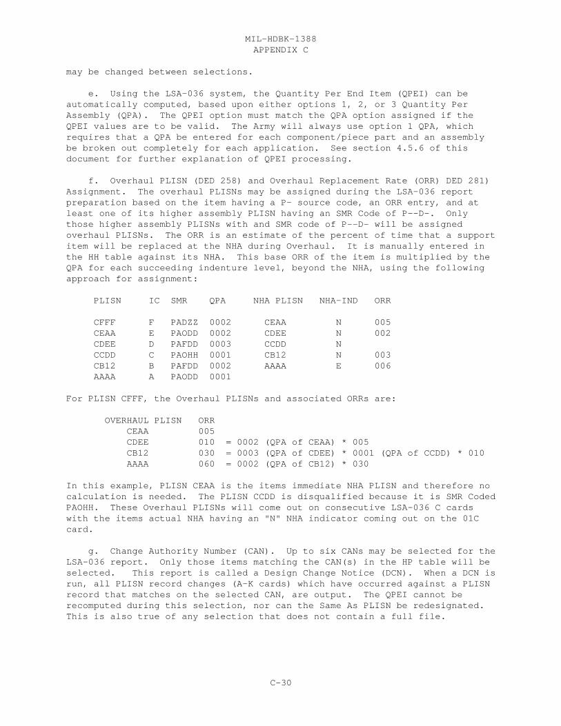
APPENDIX CMIL-HDBK-1388
C-30
may be changed between selections. e. Using the LSA-036 system, the Quantity Per End Item (QPEI) can beautomatically computed, based upon either options 1, 2, or 3 Quantity PerAssembly (QPA). The QPEI option must match the QPA option assigned if theQPEI values are to be valid. The Army will always use option 1 QPA, whichrequires that a QPA be entered for each component/piece part and an assemblybe broken out completely for each application. See section 4.5.6 of thisdocument for further explanation of QPEI processing.
f. Overhaul PLISN (DED 258) and Overhaul Replacement Rate (ORR) DED 281)Assignment. The overhaul PLISNs may be assigned during the LSA-036 reportpreparation based on the item having a P- source code, an ORR entry, and atleast one of its higher assembly PLISN having an SMR Code of P--D-. Onlythose higher assembly PLISNs with and SMR code of P--D- will be assignedoverhaul PLISNs. The ORR is an estimate of the percent of time that a supportitem will be replaced at the NHA during Overhaul. It is manually entered inthe HH table against its NHA. This base ORR of the item is multiplied by theQPA for each succeeding indenture level, beyond the NHA, using the followingapproach for assignment:
PLISN IC SMR QPA NHA PLISN NHA-IND ORR
CFFF F PADZZ 0002 CEAA N 005 CEAA E PAODD 0002 CDEE N 002 CDEE D PAFDD 0003 CCDD N CCDD C PAOHH 0001 CB12 N 003 CB12 B PAFDD 0002 AAAA E 006 AAAA A PAODD 0001
For PLISN CFFF, the Overhaul PLISNs and associated ORRs are:
OVERHAUL PLISN ORR CEAA 005 CDEE 010 = 0002 (QPA of CEAA) * 005 CB12 030 = 0003 (QPA of CDEE) * 0001 (QPA of CCDD) * 010 AAAA 060 = 0002 (QPA of CB12) * 030
In this example, PLISN CEAA is the items immediate NHA PLISN and therefore nocalculation is needed. The PLISN CCDD is disqualified because it is SMR CodedPAOHH. These Overhaul PLISNs will come out on consecutive LSA-036 C cardswith the items actual NHA having an "N" NHA indicator coming out on the 01Ccard.
g. Change Authority Number (CAN). Up to six CANs may be selected for theLSA-036 report. Only those items matching the CAN(s) in the HP table will beselected. This report is called a Design Change Notice (DCN). When a DCN isrun, all PLISN record changes (A-K cards) which have occurred against a PLISNrecord that matches on the selected CAN, are output. The QPEI cannot berecomputed during this selection, nor can the Same As PLISN be redesignated. This is also true of any selection that does not contain a full file.

APPENDIX CMIL-HDBK-1388
C-31
h. PLISN range selection. The user may select up to five Start andStop PLISN ranges for inclusion on the LSA-036. Both the Start and Stop PLISNand all qualified PLISNs between are included on the report. All other PLISNsare excluded.
i. Part III selections. The two optional part III selections are theArmy edit Routine (option 1) and the Air Fore L card Merge (option 2). Theseoptions are explained in more detail later in this chapter.
j. Output options are combinations of the following; live run withoutheaders (which will allow QPEI, ORR, calculations, Same as PLISN recognitionand update the baseline file and the LSAR data tables); test bump withoutheaders (which will look exactly like the live run except does not update thebaseline file or data tables); database dump without headers (this will be astraight dump of the LSAR data base without any calculations); and all of theabove with headers.
4.5.4 CONTROL DATA. The report will display the following provisioningreport control data not contained in the LSAR:
a. Card Sequence Number (CSN). A two-position numeric code which is usedto sequence multiple data input cards for a specific card format indicator. The initial card entry is coded 01. Subsequent cards are coded 02-99.
b. Card Format Indicator (CFI). A one-position alphabetic code: A-H, J-Mused to identify a card format and content.
c. Reference Designation Overflow Code (RDOC). A one-position alphabeticcode: A and B used to link a long Reference Designation which exceeds 32characters. Code "A" is entered against the first 32 characters, and code "B"is entered against the last 32 characters.
4.5.5 PROVISIONING BASELINE FILE (PBF).
a. The PBF is a file within an LSAR ADP system, which isonly accessible through the LSA-036 system. It is an exact image of the data,which is delivered to the requiring authority. The PBF contains allprovisioned end items included in the LSAR.
b. Each PCCN contained in the PBF includes all previously selectedprovisioning lists. Updates against a PCCN will reflect changes from the PMFmade since the last LSA-036 processing cycle. The items included in the PBFmust match at least one of the PTD Selection Code subfields from the LSAR toqualify. If an item qualifies under more than one selected provisioning list,only one consolidated file is maintained and updated. The LSA-036 hard copyreport summary page will list the current and all previously selected PLs.
c. A PBF can be developed against any PL. For instance, if an LLTIL isrequired 2 years before generation of the completed PPL, this list can beestablished in the PBF, and updates to the LLTIL can be provided for the timebetween its delivery and the delivery of the PPL. A reserved set of PLISNscan be used for these items, and prior to delivery of the PPL, these PLISNs

APPENDIX CMIL-HDBK-1388
C-32
can be reassigned to the appropriate locations within the PPL. At this point,no update of the PBF should be requested and only hard copy review LSA-036reports should be prepared until the PPL is reviewed by the requiringauthority. After approval when the PBF is updated with the PPL submission,the LSA-036 report would contain the LLTIL items incorporated into the PPL anddelete PLISN transactions for the long lead items under their reserved PLISNs.
d. The PBF serves as the input file when LSA-036 update transactions areto be generated. It consists of a header record, which contains theinformation from the most recent LSA-036 report selection to include, UOCs,QTY/EI option, and type of output. It also contains a record of previous PLsselected. When selecting an update LSA-036 report, the UOCs entered must beequal to or greater in content than the UOCs entered on previous selectionsagainst the PCCN, and the UOC suppression must be identical to previousselections for that PCCN or the report will reject. The PBF file contains allPCCNs qualified from the LSAR and is sequenced in ascending PCCN/PLISN.
4.5.6 QPEI CALCULATION.
a. The LSA-036 system can compute QPEI based upon the Quantity PerAssembly (QPA) option chosen when quantities were assigned. There are threeQPEI options to go along with three QPA options. These options will bediscussed in greater detail in this chapter.
b. Within the LSA-036 system, the QPEI calculation is performed beforefinal qualification of a PLISN record for inclusion on the LSA-036 report.
4.5.6.1 OPTION 1 QUANTITY PER END ITEM.
a. Normally the Army will utilize option 1, QPA/QPEI. For this optioneach part is rolled up at each location (part application) and then eachlocation is summed up to give the total QPEI for that item. Figure 12 showsan example of option 1 processing. Notice that the every part in the systemin broken out to the piece part level.
b. For all QPEI options, the QPA contained on LCNs with ALCs other than"00" are not included in the grand total for a reference number, unless thereare no "00" ALCs for the item. In this case, all ALC subtotals are summed todetermine the QPEI. An example of the QPEI computation, based on combinationsof "00" and nonbasic ALC applications, is depicted in figure 9. Note: Itemswith asterisk ICs are also not included in the QPEI total.

APPENDIX CMIL-HDBK-1388
C-33
FIGURE 12. Option 1 Quantity Per End Item (ARMY)
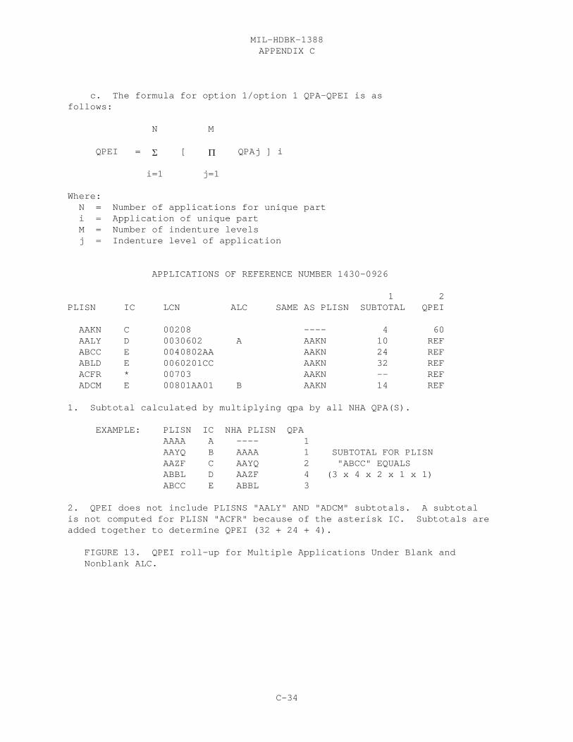
APPENDIX CMIL-HDBK-1388
C-34
c. The formula for option 1/option 1 QPA-QPEI is asfollows:
N M
QPEI = � [ � QPAj ] i
i=1 j=1
Where: N = Number of applications for unique part i = Application of unique part M = Number of indenture levels j = Indenture level of application
APPLICATIONS OF REFERENCE NUMBER 1430-0926
1 2PLISN IC LCN ALC SAME AS PLISN SUBTOTAL QPEI
AAKN C 00208 ---- 4 60 AALY D 0030602 A AAKN 10 REF ABCC E 0040802AA AAKN 24 REF ABLD E 0060201CC AAKN 32 REF ACFR * 00703 AAKN -- REF ADCM E 00801AA01 B AAKN 14 REF
1. Subtotal calculated by multiplying qpa by all NHA QPA(S).
EXAMPLE: PLISN IC NHA PLISN QPA AAAA A ---- 1 AAYQ B AAAA 1 SUBTOTAL FOR PLISN AAZF C AAYQ 2 "ABCC" EQUALS ABBL D AAZF 4 (3 x 4 x 2 x 1 x 1) ABCC E ABBL 3
2. QPEI does not include PLISNS "AALY" AND "ADCM" subtotals. A subtotalis not computed for PLISN "ACFR" because of the asterisk IC. Subtotals areadded together to determine QPEI (32 + 24 + 4).
FIGURE 13. QPEI roll-up for Multiple Applications Under Blank and Nonblank ALC.

APPENDIX CMIL-HDBK-1388
C-35
Figure 14. Option 2 Quantity Per End Item (Navy).
APPENDIX CMIL-HDBK-1388
C-36
4.5.6.2 OPTION 2 QUANTITY PER END ITEM.
a. The option 2 QPA/QPEI combination is primarily utilized by the Navy. The primary difference between this option and option 1 is that the option 2QPA, represents a roll-up of the assembly piece parts, which includes thetotals for the subsequent appearances of the assembly. Intermediate totals,which are entered by the analyst in the QPA field, are merely added togetherusing this option. A sample of this calculation is shown in Figure 13.
b. The following formula applies for option 2 QPA/QPEI:
N
QPEI = � QPAi
i=1
Where: N = Number of applications for unique part i = Application of unique part
4.5.6.3 OPTION 3 QUANTITY PER END ITEM.
a. The option 3, QPA/QPEI, requires that the LSA-036 system generateassembly breakdowns, where only the "first appearance" or application of theassembly is completely broken down to piece part level. These generatedbreakdowns are then used to compute the QPEI for each of the itemsapplications. This is performed by determining what items are assemblies(have lower indentured parts), and then by means of the Same as PLISN,determining whether or not these assemblies are "broken out" at theirsubsequent appearance(s). When it is detected the subsequent appearance isnot broken out, the first appearance breakdown is then generated in the filefollowing the subsequent appearance assembly PLISN record by using this basicPLISN, and then appending to it the PLISN assigned to the assembly componentsin the first appearance breakdown. Utilizing this "mother PLISN" and the ICto maintain descending family tree relationships, the breakdown legs of thegenerated piece parts are then subtotaled to the reference number QPEI total. The "mother PLISNs" ICs are reassigned at the generated breakdown based uponthe difference between the IC of the first appearance and subsequentappearance(s) of the assembly.
b. This technique of generated breakdowns is illustrated in figure 15.The LSAR file condition requiring the use of this technique is primarily usedby the Marine Corps, although it does provide an efficient/space saving methodof file construction.

APPENDIX CMIL-HDBK-1388
C-37
Figure 15. Option 3 Quantity Per End Item (Marine Corps)

APPENDIX CMIL-HDBK-1388
C-38
c. The following formula applies to option 3 QPA/QPEI:
N M P-1 Q
QPEI = � [ [ � QPAj ] + � [ � QPAl ] k ] i
i=1 j=1 k=1 l=1
Where: N = Number of applications of unique part (first appearance of NHA only) i = Application of unique part M = Number of indenture levels j = Indenture level of application of first appearance P = Number of applications of unique assembly containing unique part k = Application of unique part (other than first appearance of a higher assembly) Q = Number of indenture levels at assembly application (other than first appearance of a higher assembly) l = Indenture level of application (other than first appearance of a higher assembly)
Note: (1) The Greek "�", or SIGMA, represents the mathematical symbol for aseries summation, while the symbol "�", or TAU, is the mathematicalexpression for a series multiplication.
(2) The first product and summation in this formula are performedagainst the first appearance of an item. These applications are documented inthe LSAR hardware breakdown. The second product and summation are performedagainst subsequent appearances of an item which are not documented in the LSAR(e.g., will not appear on a PPL). These item applications are identified bythe first appearance of the item in an assembly (either NHA or higher), andthe Reference Number of the higher assembly containing the unique partappearing in multiple applications.
4.5.7 SAME AS PLISN.
a. Same as PLISN (DED 364). The QPEI is one of two data elements thatassigned or updated during LSA-036 processing. The other, the Same as PLISN(SAP), will be assigned during LSA-036 summary preparation. The SAP will beautomatically updated in the PMF (HG table) and the PBF except if a theselection is made not to update the baseline or master file. The SAP is thelowest EBCDIC value PLISN of all part applications for a given referencenumber.
b. The Same As PLISN is used to determine the QPEI. After the QPEIcalculation is performed, the actual QPEI is entered on the lowest value PLISNand reference requirements for subsequent or higher valued PLISN applicationsof the same reference number are determined, and the appropriate referencecode (REF, reference; or, REFX, reference assembly) is assigned to the QPEIfield. The REFX code is assigned using option 2, QPEI, in the same manner as
APPENDIX CMIL-HDBK-1388
C-39
the determination of the nonbreakout of a subsequent appearance of anassembly. Figures 9 and 10 also depict the assignment of Same as PLISN andREF/REFX.
4.5.8 UPDATE TRANSACTIONS.
a. LSA-036 Update and Design Change Notices. There are five basic typesof LSA-036 updates which can result when LSAR data is added, changed ordeleted affecting PL‘s previously delivered. These transactions can beautomatically generated using a validated LSAR ADP system by establishingbaseline records upon initial submission of the LSA-036. These transactionsare based upon a comparison of the current LSAR provisioning oriented datatables and provisioning data baselined by a previous LSA-036 submittal.
(1) Standard Data Update. For each LSA-036 card affected by datawhich has been added or changed since the previous PL delivery or LSA-036update, mandatory data, i.e., PCCN, PLISN, CSN, and CFI, and "M" TOCC and theadded/changed data only are entered. If data has been deleted, a "G" isentered in the TOCC and in the left most position of each field deleted on theappropriate LSA-036 card. Data deletions and changes/additions occurring onthe same LSA-036 card will require both a change and deletion card for theappropriate data. It should be noted that "T" TOCC is not used by theautomated LSA-036 reports and only apply to mannually prepared LSA-036reports.
a. If all data on an LSA-036 CFI is deleted, a delete transactionwill be generated consisting of the PCCN, PLISN, CSN "01", CFI (Except A), thekey data associated with that CFI, and a "G" TOCC. Conversely, if data iscontained in the PMF which does not appear in the PBF, and this data wouldcause a new LSA-036 record, an "M" TOCC will be gnerated for the added cardrecord. TOCCs will only be displayed for established PLISN records. A new or"first time" appearance of a PLISN will always have a blank TOCC.
b. When an entire PLISN record is deleted (HG record), a deletetransaction will be generated consisting of the appropriate PCCN, PLISN, CAGE,Reference Number, and a "D" TOCC on the "01A" card. Also, there should be anoption for the reference designation, that if it exists, it is displayed withthe PCCN and PLISN on the "01D" card with a "G" TOCC. In addition, if anychange authority related information is changed, CFIs "F", "G", and "H" updatetransactions are also processed.
(2) Quantity Data Update. When a quantity field is updated,mandatory data, a "Q" TOCC and the updated quantity data field(s) are entered. This will only apply to the following data: Quantity Per Assembly, QuantityPer End Item, Total Quantity Recommended, Allowance Item Code Quantity,Minimum Replacement Unit, Recommended Initial System Stock Buy, RecommendedMinimum System Stock Level, Recommended Tender Load List Quantity, QuantityShipped, Quantity Procured and Prorated Quantity. When additional datadisplayed on the same LSA-036 card also changes during the update, only onechange card is entered with TOCC, "Q". When quantity data is deleted, achange card is entered with a zero filled quantity field and TOCC "Q". Note: When a quantity field is initially established, eg. from a blank to a numeric
APPENDIX CMIL-HDBK-1388
C-40
value, a TOCC of "M" is assigned.
(3) Key Data Update. Certain provisioning data are considered keyand associated data elements. These are listed below. Changes to key datarequires the submission of both a delete and change card for the appropriatekey data. The deletion card should contain a "G" TOCC and the original keydata. The change card should contain an "M" TOCC with the new key data andthe applicable associated data. Deletion of key data will result in deletionof the corresponding associated data. Note that certain key data, i.e.,Serial Number Effectivity and Figure Number and Item Number, appear under boththe key data column by itself, or with another key, and alos under theassociated data column. These key data are actually subordinae to the keysfor wich it is associated. This means that without the primary keys (ChangeAuthority Number and TM Code), these subordinate keys will never be displayed. When combinations of data arelisted under the key data, these fielda reconsidered as one key field with blank subordinate keys permissible. Adeletion of the key data in the PMF results in deltion of associated data tothe key data in the PBVF and generation of an LSA-036 deletion transationonly. The assocaited data will only be reinstated when the key data is re-entered into the parts file.
(4) Associated Data Update. Changes to associated data requires thesubmission of a change card consisting of an "M" TOCC with the changed dataand entry of the applicable key data. Deletion of associated data requiresthe submission of a deletion card with a "G" TOCC, a "G" in the left-mostposition of the associated data field and entry of the key data.
(5) Design Change Notices (DCN). DCN information is notdistinguished from other updated data for a particular LSA-036 update using avalidated LSAR ADP system. DCN’s can be processed as a separate anddistinguishable report by specifying that DCN affected data must be processedas an exclusive update, i.e., by performing an LSA-036 update, entering theDCN information into the LSAR, and by again running an LSA-036 update. Anoption to obtain an LSA-036 report for updated data pertaining to specificDesign Change Authority Numbers is provided on the LSA-036 options. DCNinformation updates are similar to other update transactions with thefollowing exception. When a Change Authority Number and Serial NumberEffectivity are entered, an "L" TOCC is entered for the replaced item. If aquantity change occurs on limited effectivity item, an "L" TOCC is entered inlieu of a "Q".
4.5.8.1 UPDATE PROCESSING.
a. Several data elements are combined/updated as one field. These arethe Reference Number and CAGE on the 01A card and all CSN for Remarks andProvisioning Nomenclature within its TM Code, Figure and Item Numbers key.Since an update to Remarks or Provisioning Nomenclature may be of a shorterfield length than the original data, the original data is deleted using dataelement deletes (or "G" TOCC) in either the standard or key data deleteformat, respectively, prior to updating these elements. Key, subordinate key,and associated/combined date relationships are depicted in figure 11.

APPENDIX CMIL-HDBK-1388
C-41
b. The CSN will always begin with CSN "01" for any CFI updatetransaction. An exception is the CFI "A" update of an Additional ReferenceNumber which will begin with CSN "02". If there are multiple data updates ofa PLISN CFI, the CSN will be incremented by one for each multiple updaterequired. The TOCC type within a set of CFI is also used to determine theCSN. Delete transactions (TOCC "G") are grouped for determination of the CSNfor a PLISN CFI. If a CFI update includes both delete/change transactions(TOCC "L", "M", and "Q"), the CSN is again resequenced back to "01" when thetransactions transition from the delete to the change types.
c. Deletion transactions will always appear before change transactionswithin a given CFI. A new PLISN can only have blank TOCC, which will includean incremented CSN for multiple CFI data.
d. There are no "reserved" additional reference numbers (ARN). TheARN will be displayed on CSN based upon a sort in ascending CAGE and ARN(first 29 positions). It is necessary to control "reserved" ARN, e.g.,drawing number, by using the Reference Number Category Code (RNCC). RNCC "D"indicates a drawing reference number and RNCC "C", or "7" depictsnondefinitive Military Specifications or Standards.
e. DCN-UOC and Serial Number Effectivity are depicted as subordinatekeys, and as such, multiple entries against a single Change Authority Numberare permitted. The same is true of BOI-CTRL within a TM Code FigureNumber-Item Number combination key, or Figure Number/Item Number within a TMCode key.
f. The analyst may change a CSC in the parts file which contains keydata without generating an update transaction, if the key data itself remainsunchanged.
g. If more than one WUC/TM FGC is entered in the parts file withoutthe required key(s), only the WUC/TM FGC appearing on the lowest CSC will bedisplayed on the LSA-036 report (this allows an Air Force WUC to be outputwithout the required TMC,FIG-NO,ITEM-NO key required for a TM FGC).
h. Unit of Measure (UM) Price processing.
(1) When more than one UM Price is in the parts file for a givenReference Number-SCC combination, a "Y" Provisioning UM Price Code (PUC)should be documented against only one of these UM Prices. This price will beextracted for the LSA-036 report.
(2) If more than one UM Price in the parts file contains a "Y"PUC, no UM Price will be output.
(3) If no multiple/single UM Price contains a "Y" PUC, the firstUM Price containing a blank PUC will be displayed.
(4) If all UM Prices contain "N" PUCs, no UM Price will be output.

APPENDIX CMIL-HDBK-1388
C-42
Table I. Provisioning Key and Associated Data.
APPENDIX CMIL-HDBK-1388
C-43
i. Multiple, independent key data deletes/updates contained on thesame CFI, e.g., UOC and Reference Designation, are consolidated on one cardrecord under the appropriate TOCC.
j. A Reference Designation change on a portion of a long ReferenceDesignation (determined by the Reference Designation Overflow Code (RDOC))will result in update transactions to both card records of the ReferenceDesignation, even if one of the card records is unchanged. Long ReferenceDesignations (RDOC "A" and "B") must appear on consecutive CSC in the partsfile. An RDOC A without RDOC B following long Reference Designation will notbe output on the LSA-036, but will appear with an error message on the LSA-036Part II error listingCAGEreport. (By this criteria, the RDOC appears to process similar to a combinedkey with Reference Designation, on update transactions.)
k. Identical key data within a PLISN record will be merged andprocessed as a single update transaction. Care should be exercised to ensurethis condition does not exist in the file.
l. If multiple, subordinate key data are contained within anotherkey, e.g., Basis of Issue Control within a TM Code-Figure Number Item Numbercombination key and DCN-UOC within a Change Authority key, the nonmultipleassociated data, i.e., TM Indenture or Total Item Changes, only appear on thefirst CSN containing the basic key.
m. If an entire PLISN record is deleted from the PBF, a one-linerecord in the image of the PLISN deletion transaction will remain on the PBF.If that exact, deleted PLISN is reinstated/re-established in the PMF, it mustmatch the CAGE and Reference Number that were contained on the record when itwas originally deleted.
4.5.9 THE LSA-036 REPORT HEADER.
a. The following "header" data required to identify the specifiedlist(s) are not a part of the LSAR but are contained in the LSA-036 summary.
(1) Procurement Instrument Identification (PII). A 19-positionalphanumeric entry used to identify a specific contractual document. The PIIincludes the PII number (PIIN) (13 positions), and the supplementary PIInumber (SPIIN) (6 positions).
(2) Nomenclature of model or type number. A 21-positionalphanumeric entry used to specify the name, model, or type of equipment beingprovisioned. (3) Control Data. A 10-position alphanumeric entry used forcontrol information as specified by the requiring authority. This informationmay consist of such items as identification of provisioning data inMIL-STD-1388-2 format or a Weapons System Code.
(4) Prime Contractor‘s CAGE. A five-position alphanumeric entrywhich identifies the prime contractor for the equipment being provisioned.
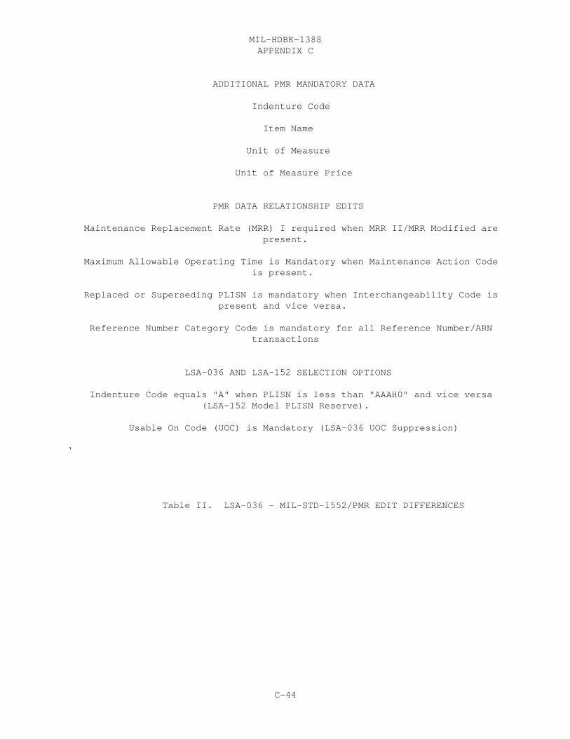
APPENDIX CMIL-HDBK-1388
C-44
ADDITIONAL PMR MANDATORY DATA
Indenture Code
Item Name
Unit of Measure
Unit of Measure Price
PMR DATA RELATIONSHIP EDITS
Maintenance Replacement Rate (MRR) I required when MRR II/MRR Modified are present.
Maximum Allowable Operating Time is Mandatory when Maintenance Action Code is present.
Replaced or Superseding PLISN is mandatory when Interchangeability Code is present and vice versa.
Reference Number Category Code is mandatory for all Reference Number/ARN transactions
LSA-036 AND LSA-152 SELECTION OPTIONS
Indenture Code equals "A" when PLISN is less than "AAAH0" and vice versa (LSA-152 Model PLISN Reserve).
Usable On Code (UOC) is Mandatory (LSA-036 UOC Suppression)
‘
Table II. LSA-036 - MIL-STD-1552/PMR EDIT DIFFERENCES

APPENDIX CMIL-HDBK-1388
C-45
(5) Submission Control Code. A five-position numeric entry usedto control the submission of provisioning data. The first submission will be0000l, and each subsequent submission is to be numbered sequentially, onegreater than the prior submission.
(6) Date list submitted. A six-position numeric entry used toidentify the date of submission. The first two positions will identify theyear, the next two will identify the month, and the last two will identify theday.
b. The LSA-036 report contains a one-page header that provides theanalyst with specific information about the current selection and a history ofprevious provisioning list selections. It also provides a series of counterswith regard to the numbers and types of total PLISN records, as well as cardrecord (CFI) counts and types of transactions against these CFIs.
c. The first line of counters on the header page concerns PLISN recordtotals for the PCCN selectted.
(1) The count under the header, "EXTRACTED FROM H DATA TABLES,"consists of all PMF records, which are initially qualified by the selectedPCCN.
(2) Under "NOT SELECTED" are records with a blank PLISN, PLISNrecords disqualified on either PTD Selection or UOC, or duplicate PLISNs.These conditions are shown on the LSA-036 Part II error listing with a messagesimilar to, "PLISN bypassed in 36". This error message and most errormessages on this report will depend on the software vendors choice of words.
(3) The next four columns of information are PLISN record (or "01A"record) totals extracted from the PBF. "EXTRACTED FROM PROV BASELINE" are thePLISN records established on the input PBF. "ADDED TO PROV BASELINE" are thenew PLISN records added in this processing cycle. "DELETED FROM PROVBASELINE" is a total of all PLISNs contained in the PBF which have a "D" TOCC. This total represents the output file condition and not simply a total of thecurrent processing cycle. The last column, "NEW PROVISIONG BASELINE," is atotal number of PLISNs contianed in the baseline file after all adds anddeltes have been processed.
d. The last set of counters, "LSA-036 RECORD COUNTS," are card recordtotals by CFIs and three groupings of TOCC (additions, changes, and deletions)for those items appearing in the LSA-036 report listing on the currentprocessing cycle.
e. Also appearing on the LSA-036 report header are a recapitulation ofthe current report selection parameters, as well as a listing of allpreviously selected provisioning lists which comprise the consolidated PBF.These previous lists will only appear, if the current selection requires a PBFcomparison and an extract of change transactions only.
f. The header section is used for error messages when a subsequentLSA-036 report selection violates the previously selected report criteria by

APPENDIX CMIL-HDBK-1388
C-46
either narrowing the UOC selections, or by changing the UOC suppression optionbetween selections. Only the header page of the LSA-036 report is generated.
4.5.10 THE LSA-036 PART II ERROR REPORT.
a. The LSA-036 part II error listing is automatically produced when anLSA-036 is requested. The standard section lists those PLISNs matching thePCCN selected which were disqualified or would degrade the provisioning list. This list must be reviewed by the user to ascertain what corrections, if any,are needed to update the parts data tables for subsequent update(s) to theprovisioning list.
b. Since the LSA-036 does not match the input edits of the PMR, theLSA-036 Part II error listing can be used to review the parts filefor the minimum mandatory data requirements to establish a PMR PLISN record.These "minimum data" are the same elements which were originally establishedunder MIL-STD-1552 and are included in table II. Also included in the tableare the data edit relationships required by the PMR, which are not in theLSA-036 system, and the PMR edits which can only be satisfied using theselection options of the LSA-036 and 152 reports. The part III Army Editoption may be selected in leu of the part II error listing.
c. The LSA-036 Part II error listing is displayed in PLISN sequence andshould be made available by the preparing activity during LSAR/Provisioningreviews. It also includes the Reference Number and LCN keys, so that thepreparer may readily make corrections to the PMF.
e. The ability to tailor this report is dependent apon the LSAR ADPsystem being used. The only errors that must come out on this report areitmsa that were bypassed based on PTD seletion or UOC or becuasue the PLISNwas duplicated.
4.5.11 LSA-036 PART III OPTIONS. There are two LSAR-036 part IIIoptions, the LSA-036 Army Edit routine and the Air Force "L" card mergeroutine.
4.5.11.1 ARMY LSA-036 SYSTEM EDITS.
a. The Army LSA-036 edits were developed by a special task forcerepresenting each Army MSC and established by the CCSS PMR FCG.
b. These edits provide front-end edit and data compatibility checks priorto loading this information into the PMR. There are 42 optional edit switcheswhich the user may specify. All but two of these edits will cause the LSA-036system to discontinue final processing when an edit error condition isencountered. The edit switches may be turned "on" and "off" during trialLSA-036 runs by the preparing activity.
c. The requiring authority may specify in the LSA/LSAR Statement of Work,that specific switches must be used when an LSA-036 summary is generated foractual delivery to the requiring authority and stipulate the hard copy LSA-036and LSA-036 Part II error summaries be delivered with the LSA-036, 80/80
APPENDIX CMIL-HDBK-1388
C-47
magnetic tape.
4.5.11.2 AIR FORCE "L" CARD MERGE ROUTINE.
a. The Air Force "L" card contains information concerning basiccataloging and support item quantity requirements, substitute or preferredpart numbers, and support item delivery schedules.
b. The ADP system should merges "L" card data with other card data when the tape option is seltectd.
4.6 PROVISIONING UTILITIES. There may be several utility/optional LSARADP system routines available to assist and enhance the provisioning process. Here are some that may be available:
a. SESAME Extract Program
d. Government to Contractor Parts Master File Update Routine
e. LSA-036 to PMF Transactions
g. QPEI Calculation by UOC
h. Other provisioning utilities
4.6.1 SESAME EXTRACT PROGRAM. This would be a utility to extract theLSAR data and input it into the SESAME model. SESAME is a "sparing toavailability" model which optimizes the spare/repair part stockage levels foreach operation/maintenance level. Earlier in the program life cycle, themodel can be used for tradeoff analysis and provisioning budget forecasts. The core SESAME program written in FORTRAN IV. More information can beobtained by contacting U.S. AMSAA-IRO, Room 800 U.S. Custom House,Philadelphia, PA 19106-2976, DSN 444-3808, commercial (215) 597-8377.
4.6.2 GOVERNMENT /CONTRACTOR PBF COMPARISON. This routine may beavailable to compair government and contractor PBFs and give a discrepancyreport. This routine may allow updates if desired.
4.6.3 LSA-036 TO PMF UPDATE TRANSACTIONS. An LSAR ADP system maycontain a utility to take a LSAR-036 report and convert it to the H datatables.
4.6.4 QPEI CALCULATION BY PCCN AND UOC. This utility wouldautomatically compute QPEI by any of the three options selectable using theLSA-036 system. It should be noted that the layout of the data tables doesnot allow for a part applicaion that is used on multiple UOCs to have multipleQPA/QPEI values.
APPENDIX CMIL-HDBK-1388
C-48
5. REPAIR PARTS AND SPECIAL TOOLS LIST (RPSTL)
5.1 RPSTL CONTENT. The draft/proof RPSTL consists of four sectionsprepared IAW MIL-STD-335(TM) or MIL-M-49502(TM) (Reference MIL-M-49502(TM),paragraph 6.4, for applicable document):
a. Section I, Introduction
b. Section II, Repair Parts List
c. Section III, Special Tools List
d. Section IV, Cross-Reference Indexes
Sections II, III and IV listings are produced as separate sections of thisreport. The lists may be printed on plain bond paper or may be output to aword processor file to be used as source information for final RPSTLpreparation.
5.2 REPORT SELECTION. These proof options is selected by mandatory TMCode from table HK. The draft option is selected by mandatory EIAC, Start LCNand TM Code. The draft has optional Stop LCN, ALC, and UOC selections. Additional optional selections for both the proff and draft are by O/M Leveldetermined by the third (remove) position of the Source Maintenance andRecoverability Code (SMRCODHG) and Start and Stop range(s) of FGCs. (NOTE: The only differences between the proof and draft RPSTL format involves displayof the file control keys following the standard columns 1 through 6 (or 7).) Both the proof anddraft RPSTL have the option of depicting the formats prescribed by eitherMIL-STD-335(TM), or MIL-M-49502(TM)
a. The four cross reference indexes in part IV of the RPSTL, are eachseparately selectable.
b. Functional Group Code (FGC) Headers are also optional inputs for theRPSTL report. For the 30 report you have header information which is athroughput. For each Functional Group header there will be a Start and StopTM-FGC header. Each Functional Group Header can consist of up to 9 lines ofheader information. Each line of header information is 36 positions long.There is not a minimum or a maximum number of FGC headers/Start and Stop TM-FGC.
c. There is an additional selection option, Start Stop TM-FGC. There isa maximum number of 4 start and stops TM-FGCs. The Start Stop TM-FGC willallow the report requester to select specific TM FGCs to be output. Theyshould be processed like start and stop LCN’s (Start TM-FGC � TM-FGC < StopTM-FGC, except when start and stop TM-FGC’s are equal then select that TM-FGConly.
5.3 DOCUMENTATION OF KITS FOR RPSTL. In order to produce kit/kitcomponent listings for the RPSTL, a kit record first must be established and a

APPENDIX CMIL-HDBK-1388
C-49
Provisioning List Item Sequence Number (PLISN) assigned to this item. In thedata table, Overhaul-Kit NHA PLISN, against the application of the kitcomponent record, an NHA PLISN entry of the Kit PLISN with an NHA PLISNIndicator of "*" is required. Where the kit component appears in the RPSTLhardware breakout, the phrase "PART OF KIT P/N" (automatically generated),followed by the reference number of the kit, will be displayed following theprovisioning nomenclature in the description column. The Kit Reference Numberis determined by a match of the Kit NHA PLISN to a PLISN under the same PCCNin the parts application provisioning data table. One item may be used inmultiple "kits" by multiple kit NHA PLISN HH entries. The kit components areautomatically generated beneath the kit. The component listing contains theapplicable figure number, item number and quantity per assembly/figureduplicated from the hardware breakout information.
5.4 DATA CONTENT.
a. FGC Headers are placed in the description column preceding the firstrow of data matching on FGC with the FGC header key.
b. The PART NUMBER column contains 16-positions of the Reference Number.If the Reference Number exceeds 16 positions, the remainder is printedimmediately beneath the first 16 on the next line.
c. Rows are sorted by section and FGC sequence. For the descriptioncolumn, the item name will first appear, then two spaces followed by theprovisioning nomenclature, if applicable. If the Hardness Critical Item(Table HG) is "Y", then the symbol "(HCI) is printed one space following theItem Name and two spaces before the provisioning nomenclature. Trailingperiods are placed following the last position of the item name/provisioningnomenclature to the end the description column. If the row also has a TMIndenture Code entry, then leading periods are placed prior to the item nameof the row, equalling the number in the TM Indenture Code field.
d. Following the privisioning nomenclature, on a separate line applicableUOCs of the row are entered. preceded by "UOC: " If the row has fulleffectivity, no UOCs are displayed. Full effectivity is determined by: A Rowin HG has full effectivity if it is represented in HO for Every XC entry whichcontain its PCCN.
e. The quantity per figure is displayed, unless blank, then the quantitytper assembly is shown.
f. Under the NSN column (MIL-STD-335 Format), a "Y" is displayed if bothFSC and NIIN are not blank and NIIN does not contain alpha characters for therow of information. Otherwise "N" is displayed.
g. Under the PLCC column, only entries of "D"s are shown.
h. After all rows of data are displayed following a FGC Header, andbefore the next FGC header the phrase "END OF FIGURE" (MIL-STD-335(TM) Formatonly) is printed. Rows of information are printed with no line skips betweenrows. At the end of a page, a page number is assigned using the figure number
APPENDIX CMIL-HDBK-1388
C-50
from the first record following the FGC header, followed by dash then "1",multiple pages of the same figure follow the same pattern, e.g., 3-1, 3-2,3-3, etc. A page break will occur with each new FGC Header set under adifferent FGC. If no FGC Header inputs are provided, then the sorted rows are"page breaked" each time the figure number changes.
i. The section III description column is similar to the Section IIdescription with the addition of the interpreted Basis of Issue(BOI). EachBOI is displayed by "BOI:" and its quantity, then either Basis of Issue Levelor Basis of Issue End Item is interpreted (See DED 030 of MIL-STD-1388-2B). Basisi of Issue End Item is preceded by "PER" and followed by"END ITEMS". The BOI is inserted between provisionnomenclature and the Usableon Code lines.
j. Section IV cross reference indexes are produced as optional outputs asspecified by the requester. The Reference Designations for the ReferenceDesignation Index will either only include those items having a nonidentifyingmigrating key of the appropriate Figure and Item Number. If these keys arepresent, or will include all related Figure Number, Item Numbers, and TM Code,if these keys are not in table HJ. Overflows of Reference Numbers orReference Designations exceeding 16 or 32 positions, respectively are printedon the next line immediately below the first portion of the element.
5.5 DRAFT/PROOF RPSTL REVIEW.
a. While the formal RPSTL report ends after the QUANTITY field column,additional information is provided on each report line record to assist theanalyst in correcting/refining the final RPSTL product. These include:
(1) TM Code. This is the basic selection criteria of the Proof RPSTLand is displayed for review when selecting the draft/proof report.
(2) WUC/TM FGC and LCN/ALC. These are selectable primary sortcriteria of the report line records.
(3) PLCC and ICC. These determine the section, repair part or tool,the report line record will be displayed on the proof and draft RPSTL,respectively.
(4) Figure Number and NSN Indicator. Figure Number is a secondarysort criteria of the draft RPSTL and must be accurate to producecross-reference indices. The NSN indicator can be reviewed to check whetheror not an NSN is in the LSAR for "P" source coded items.
b. The PLISN does not appear in the line of review data; however, if aduplicate PLISN is contained in the proof RPSTL records which matches exactlyon WUC/TM FGC and Item Number, then an error message "*** DUPLICATE PLISN ***"will appear in the description column of the report record. This can occurwhen a PLISN record contains multiple TM Code, Figure Number and Item Numberkey with an identical associated WUC/TM FGC and a different Figure Number, oron the rare occasion when the WUC/TM FGC Item Number and PLISN match for itemscontained under different PCCNs.