Embed Size (px)
Citation preview

LOCK MANOEUVRES: PRACTICAL CASES IN EUROPE AND PANAMA
K Eloot, Flanders Hydraulics Research, Ghent University, Belgium
M Vantorre, Ghent University, Belgium
J Verwilligen, Flanders Hydraulics Research, Belgium
D Bus, R Cleeren and E Gheyle, Flemish Pilotage, Belgium
E Veche, Station de Pilotage de Dunkerque, France
E Heugen and J van Drongelen, Dutch Pilotage, the Netherlands
R Salas, Panama Canal Pilots, Panama
R Detienne, Brabo, Belgium
SUMMARY
Lock manoeuvres are daily practice for the ships in their approach to harbours worldwide. The experiences of five
pilotages operating in Europe (Belgium, France and the Netherlands) and Panama are brought together in a paper
describing the operation of pilots in the entrances to and in the locks. A division is made concerning locks with approach
walls at one or both sides of the lock and locks without approach walls. The lock construction and the approach areas are
described and compared for the locks in Panama, in Dunkirk (Charles de Gaulle lock), in Terneuzen (West lock) and in
Antwerp (Berendrecht lock). Correspondence between the lock manoeuvres and the use of tugs can be recognised and
shows that lock effects must be overcome by developing and maintaining a good strategy in pilotage which can be
shared all over the world.
1. INTRODUCTION
Lock manoeuvres are daily practice for ships in their
approach to the Flemish harbours. The Berendrecht lock
– the largest lock in the world – receives Ultra Large
Container Ships from the Mediterrean Shipping
Company on their way to the Delwaide dock. With a
cumulative overall clearance of 3 m between ship sides
and lock walls (fendering not taken into account) the
West lock in Terneuzen is accessible for 37 m wide bulk
carriers [1], [2].
Lock manoeuvres are daily practice worldwide with the
well-known Panama Canal locks since 1914. The design
of the new locks which are presently under construction
and which will allow the transit of Post-Panamax vessels
with lengths up to 366 m and beams up to 49 m is based
on a drastic modification in the lock operations, as ships
making use of the new locks will not be assisted by
locomotives, but only by tugs. To prepare this
operational change the Panama Canal Pilots have
contacted their colleagues worldwide.
Experiences obtained by a shipping company in one
harbour are often extrapolated for the access of their
vessels to other harbours. Based on the research for the
access of wide-beam ships to the West lock in Terneuzen
the port authorities and the pilotage of Dunkerque have
contacted the Knowledge Centre Manoeuvring in
Shallow and Confined Water (www.shallowwater.be) for
a comparable study for entrances to the Charles de
Gaulle lock as has been done for entrances to the West
lock.
These modified operations in new locks and the need of
increasing the ship sizes in existing locks require a
multidisciplinary investigation in which simulation
techniques are widely used by institutes as a research tool
and by pilotages as a training tool. Transfer of
knowledge and expertise helps in defining the similarities
and differences between lock operations in Europe and
Panama and how to speed up the accessibility issue
making use of the research results and the operational
processes in use in other harbours.
Based on contacts between the Flemish, Dutch, French
and Panamanian pilotages the Knowledge Centre
Manoeuvring in Shallow and Confined Water is
presenting a collection and description of the lock
operations in the existing Panama locks, the Charles De
Gaulle lock in the port of Dunkerque (France), the West
lock in Terneuzen (The Netherlands) and the Berendrecht
lock in Antwerp (Belgium). A comparison of the lock
constructions and the access channels from a ship
hydrodynamics point of view will be made. The lock
effects experienced by the pilots and the operation of
tugs will be summarised and combined with full scale
measurements executed by Flanders Hydraulics Research
and the pilotages. The paper is therefore a
multidisciplinary document illustrating the pilots’ view
on lock operations and lock effects.
2. LOCK APPROACH DESCRIPTION
2.1 LOCKS WITH APPROACH WALL
2.1 (a) Locks on the Panama Canal
Construction
The lock system of the Panama Canal consists of three
lock complexes (Figure 1), one on the Atlantic side
(Gatun Locks) and the other two on the Pacific side
(Miraflores and Pedro Miguel Locks). The purpose of
the lock system in the Canal is to raise vessels to Gatun

Lake, which is 26.5 m above sea level, so that they can
cross the Isthmus through the lake.
The locks at Gatun have three levels, and each level
raises/lowers the vessels 8.8 m in height. The locks at
Pedro Miguel have one level which raises/lowers vessels
9 m to/from Gatun Lake/Miraflores Lake. The locks at
Miraflores have two levels which raise/lower vessels
17 m from/to the Pacific Ocean/Miraflores Lake.
Figure 1: Lock complexes at the Panama Canal [3]
Figure 2: Solid approach walls and locks at the Panama
Canal
Figure 3: Detail of the solid approach wall with rubber
fenders
All the lock chambers have the same dimensions,
320.12 m in length and 33.54 m in width. The maximum
dimensions of vessels allowed in the Panama Canal have
changed through the years, finally coming up with the
well-known Panamax vessels. The maximum length
overall for commercial vessels is 289.6 m, except for
passenger and container ships which may be up to
294.2 m. The maximum beam for commercial vessels
allowed for transit is 32.31 m. The maximum allowable
draft in the Panama Canal is 12.04 m Tropical Fresh
Water.
Figure 4: Detail of the wheel fenders at the opposite side
of the approach wall
This draft provides a safe under keel clearance of at least
1.5 m over certain shallow areas in the Canal. It also
allows for a clearance of 0.50 m over the south sill of
Pedro Miguel Locks, which is the shallowest point in the
Canal.
There are two sets of locks (Gatun and Miraflores) which
have sea accesses, and are, therefore, subject to density
currents and tidal currents. Pedro Miguel Locks and the
lake entrances of Gatun and Miraflores Locks are mainly
subject to the wind and, occasionally, to currents
generated by dams or spillways located near the locks.
All sets of locks have solid approach walls (Figure 2),
which assist pilots to guide large vessels inside the locks.
These walls also act as staging areas to increase the
efficiency of the Canal by having vessels in position to
go inside the locks when they are ready to accommodate
them.
The lock walls inside the locks do not have fenders.
Only the approach walls have a combination of rubber
fenders and sliding fenders (Figure 3) and wheel fenders
at the opposite side of the lock approach wall (Figure 4).
All the locks are fitted with tracks for locomotives or
“mules” that assist vessels through the lockage. Each of
these locomotives are capable of exerting a pull of
approximately 40 tons, and they can go up to 4.8 km/h
while working a vessel. The use of locomotives has
allowed the transit of vessels through the locks in
expedient but safe manner. This is something that will
greatly differ from the new design of locks that are being
built in the expansion. The use of locomotives have also
allowed the Panama Canal to increase the size of the
ships going through the locks, maximizing the use of the
lock dimensions to the point that only 12 m can be left
between the lock gates and the vessel’s bow and stern,
and less than 1 m on each side.
Manœuvre
All vessels of 24.39 m in beam and over are assigned two
pilots and one tug which is usually placed on the
shoulder to assist them to the locks. Those of 27.74 m in
beam and over are assigned an additional tug. Vessels of
274.39 m in length overall and larger are assigned a third
pilot, bow pilot, to assist in the lockage itself.
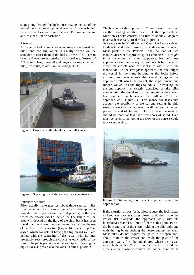
Figure 5: Bow tug on the shoulder of a bulk carrier
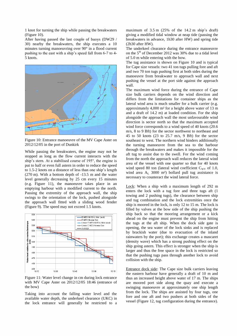
Figure 6: Stern tug in cut style assisting a container ship
Entrances sea side:
Pilots usually make tugs fast about three nautical miles
from the locks. The bow tug (Figure 5) is made up on the
shoulder, either port or starboard, depending on the lane
where the vessel will be locked in. The length of line
used will depend on the flare of the ship, but it has been
found that the shorter the line, the more effective the use
of the tug. The stern tug (Figure 6) is made up “cut
style”, which consists of having the tug placed right aft,
in line with the centreline of the vessel, with its lines
preferably sent through the chocks at either side of the
stern. The pilots prefer the same principle of keeping the
tug as close as possible to the vessel’s hull as possible.
The heading of the approach to Gatun Locks is the same
as the heading of the locks, but the approach at
Miraflores Locks consists of a turn of about 25 degrees
in a reach of 0.33 nautical miles (Figure 1).
Sea entrances in Miraflores and Gatun Locks are subject
to density and tidal currents, in addition to the wind.
Most pilots in the Panama Canal do one of two
manoeuvres when approaching sea entrances: a straight
in or stemming the current approach. Both of these
approaches use the density current, which has the most
effect on vessels near the locks, to assist with the
manoeuvre. In the straight in approach, the pilot aligns
the vessel in the same heading as the locks before
arriving, and manoeuvres the vessel alongside the
approach wall, using the current, the ship’s engine and
rudder, as well as the tugs to adjust. Stemming the
current approach is exactly described as the pilot
manoeuvring the vessel so that the bow stems the current
head on, and pivots around the “soft nose” of the
approach wall (Figure 7). This manoeuvre takes into
account the possibility of the current, setting the ship
strongly towards the approach wall before the vessel
passes the end of the wall. Both of these manoeuvres
should be made at less than two knots of speed. Care
must be taken of not going too slow or the current could
take over the ship.
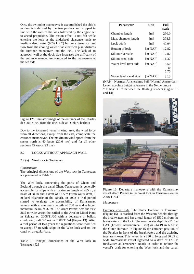
Figure 7: Stemming the current approach along the
approach wall
If the situation allows for it, pilots request the lockmaster
to keep the lock sea gates closed until they have the
vessel flat alongside the approach wall, with its
locomotives made fast (three of them at this point, two at
the bow and one at the stern) holding the ship tight and
with the tug boats pushing the vessel against the wall.
Most pilots do not request the gates to be open until
about 75 m of the vessel are inside the jaws of the
approach walls (i.e. the initial area where the vessel
meets both walls). The reason for this is to avoid the
effects of the density current at that critical point of the

manoeuvre, where the current sets the vessel strongly
against the knuckle. The effect of the current is so strong
in this area that two locomotives of 40 tons of pull each
and two tugs of at least another 40 tons each are required
to keep the vessel alongside. The effect of the current, in
addition to the piston effect at the locks, makes it
necessary to enter the locks with full ahead on the ship’s
engine in most loaded bulkers or tankers. It is known that
sometimes pilots had to wait for the density current to
dissipate to be able to enter the locks.
Entrances lake side:
Lake entrances at the locks are not affected by density
currents, but are subject to the wind and to currents
created by spillways/dams.
An example of this current occurs while manoeuvring
towards Miraflores Lock lake entrance (northern
entrance), coming from Pedro Miguel Locks, and passing
through Miraflores Lake. Pilots have come to describe
this lake as a “downhill” lake due to the fact that vessels
tend to gain speed while heading south because of the
constant spilling of water through Miraflores Dam during
the rainy season, which lasts nine months of the year.
Tugs are mostly made up the same way as in the sea
entrances, and the approaches are made taking into
account predominantly the direction and speed of the
wind. There are no operational limits for the existing
locks regarding wind force or direction. The need for
additional resources (i.e. tugs) is up to the pilot.
The northern entrance of Pedro Miguel Locks has the
additional difficulty of the hydrodynamic effects of the
banks at the Gaillard Cut.
The objective at the lake entrances is the same, to
manoeuvre the vessels alongside the approach wall so
that they pick up the locomotives and proceed inside the
locks.
Once inside the locks, the pilots use the locomotives to
tow the vessel inside, assisting with the ship’s engine and
rudder. The locomotives also keep the vessel away from
the lock walls, helping the pilot to counteract the
hydrodynamic effects that result from the solid lock
walls and the ship’s hull. The effective use of the ship’s
rudder and engine are absolutely necessary for the same
reason.
Hydraulic Assist
The Hydraulic Assist procedure is a special lockage
procedure utilized only at Gatun and Pedro Miguel
Locks. It is a means for assisting large vessels to leave
the lock chamber, when completing a down lockage, by
admitting water into the chamber behind the vessel as it
moves out. This procedure is available, upon pilot
request, for vessels having a beam over 30.2 m and draft
over 11.3 m TFW. The net effect of this procedure has
been measured by locks personnel to raise the water up
to 90 cm below the vessel, which results in the vessel
leaving the lock faster and with less resistance due to the
increased under keel clearance. Pilots have especially
found this procedure helpful when manoeuvring loaded
bulkers and tankers out of Pedro Miguel Locks, where
the smallest under keel clearance is found.
2.1 (b) Charles de Gaulle lock in Dunkirk (Figure 8)
Construction
The orientation of the lock is 260° with an approach wall
of 212 m which alignment differs from the lock wall
alignment with a value of 0.008° (Figure 9). This
deviating orientation of the approach wall will provoke a
small effect when the ship is entering the lock. The
breadth of the lock is 50 m, reduced by the fenders which
consist of tires spread over several lines on the height of
the wall. The length of the lock between outside gates is
364.36 m.
Figure 8: Charles de Gaulle lock at the port of Dunkirk
Figure 9: Approach wall of the Charles de Gaulle lock in
the port of Dunkirk
The dredged bottom depth is -13.5 m in the entrance
channel to the lock and alongside the approach wall.
Manoeuvre
Until today, the Charles De Gaulle lock at Dunkirk
allows access to the port of Cape size ships (292 m to
45.05 m) with a maximum draft of 14.35 m (generally
14.2 m). Most ships are unloaded to this maximum draft
at the western harbour and two pilots are on board while
approaching the eastern harbour.
Entrance sea side: The entrance of Cape size ships is at
mean tide only permitted 2 hours after high water (HW,
with a tidal coefficient of 85, tidal range 4.7 m and
bottom depth varying between -13 and -16 m at the
breakwaters) to be able to combine sufficient clearance
for the draft and a flow current speed reduced to less than
1 knot for turning the ship while passing the breakwaters
(Figure 10).
After having passed the last couple of buoys (DW29 /
30) nearby the breakwaters, the ship executes a 10
minutes turning manoeuvring over 90° in a flood current
pushing to the east with a ship’s speed fall from 6-7 to 4-
5 knots.
Figure 10: Entrance manoeuvre of the MV Cape Aster on
2012/12/05 in the port of Dunkirk
While passing the breakwaters, the engine may not be
stopped as long as the flow current interacts with the
ship’s stern. At a stabilised course of 195°, the engine is
put to half or even full astern in order to reduce the speed
to 1.5-2 knots on a distance of less than one ship’s length
(270 m). With a bottom depth of -13.5 m and the water
level generally decreasing by 25 cm every 15 minutes
(e.g. Figure 11), the manoeuvre takes place in an
emptying harbour with a modified current to the north.
Passing the extremity of the approach wall, the ship
swings to the orientation of the lock, pushed alongside
the approach wall fitted with a sliding wood fender
(Figure 9). The speed may not exceed 1.5 knots.
Figure 11: Water level change in cm during lock entrance
with MV Cape Aster on 2012/12/05 18:46 (entrance of
the bow)
Taking into account the falling water level and the
available water depth, the underkeel clearance (UKC) in
the lock entrance will generally be restricted to a
maximum of 3.5 m (25% of the 14.2 m ship’s draft)
giving a modified tidal window at neap tide (passing the
breakwaters in advance, 1h30 after HW) and spring tide
(2h30 after HW).
The underkeel clearance during the entrance manoeuvre
on the 5th
of December 2012 was 30% due to a tidal level
of 5.0 m while entering with the bow.
The tug assistance is shown on Figure 10 and is typical
for Cape size vessels: two 41 ton tugs pulling fore and aft
and two 70 ton tugs pushing first at both sides during the
manoeuvre from breakwater to approach wall and next
pushing the vessel at the port side against the approach
wall.
The maximum wind force during the entrance of Cape
size bulk carriers depends on the wind direction and
differs from the limitations for container ships as the
lateral wind area is much smaller for a bulk carrier (e.g.
approximately 4,000 m² for a height above water of 13 m
and a draft of 14.2 m) at loaded condition. For the ship
alongside the approach wall the most unfavourable wind
direction is sector north so that the maximum accepted
wind force corresponds to a wind speed of 40 knots (20.6
m/s, 8 to 9 Bft) for the sector northwest to northeast and
45 to 50 knots (23 to 25.7 m/s, 9 Bft) for the sector
southeast to west. The northern wind hinders additionally
the turning manoeuvre from the sea to the harbour
through the breakwaters and makes it impossible for the
aft tug to assist due to the swell. For the wind coming
from the north the approach wall reduces the lateral wind
area of the vessel with one quarter so that for 40 knots
wind speed 80 ton (lateral wind coefficient CWY of 1.0,
wind area AL 3000 m²) bollard pull tug assistance is
necessary to counteract the wind lateral force.
Lock: When a ship with a maximum length of 292 m
enters the lock with a tug fore and three tugs aft (1
towing and 2 pushing tugs), the clearance between ship
and tug combination and the lock extremities once the
ship is moored in the lock, is only 12 to 15 m. The lock is
filled by valves at the bow side of the ship pushing the
ship back so that the mooring arrangement or a kick
ahead on the engine must prevent the ship from hitting
the tugs at the aft ship. When the dock side gate is
opening, the sea water of the lock sinks and is replaced
by brackish water (due to evacuation of the inland
rainwaters by the port); this exchange creates a mascaret
(density wave) which has a strong pushing effect on the
ship going astern. This effect is stronger when the ship is
larger and thus the free space in the lock is restricted so
that the pushing tugs pass through another lock to avoid
collision with the ship.
Entrance dock side: The Cape size bulk carriers leaving
the eastern harbour have generally a draft of 10 m and
thus an increased height above water of 17 m. The ships
are moored port side along the quay and execute a
swinging manoeuvre at approximately one ship length
from the lock. The ships are assisted by four tugs, one
fore and one aft and two pushers at both sides of the
vessel (Figure 12, tug configuration during the entrance).
Once the swinging manoeuvre is accomplished the ship’s
motion is stabilised by the two pushers and stopped in
line with the axis of the lock followed by the engine set
to ahead propulsion. The piston effect is not felt while
entering the lock as the underkeel clearance tends to
medium deep water (90% UKC) but an external current
flow from the cooling water of an electrical plant disturbs
the entrance manoeuvre into the lock. The lack of an
approach wall at the dock side increases the difficulty of
the entrance manoeuvre compared to the manoeuvre at
the sea side.
Figure 12: Simulator image of the entrance of the Charles
de Gaulle lock from the dock side at Dunkirk harbour
Due to the increased vessel’s wind area, the wind force
from all directions, except from the east, complicate the
entrance manoeuvre. The maximum wind speed from the
sector north is 40 knots (20.6 m/s) and for all other
sections 45 knots (23 m/s).
2.2 LOCKS WITHOUT APPROACH WALL
2.2 (a) West lock in Terneuzen
Construction
The principal dimensions of the West lock in Terneuzen
are presented in Table 1.
The West lock, connecting the ports of Ghent and
Zeeland through the canal Ghent-Terneuzen, is generally
accessible for ships with a maximum length of 265 m, a
beam of 34 m and a draft of 12.5 m (fresh water draft, 1
m keel clearance in the canal). In 2008 a trial period
started to evaluate the accessibility of Kamsarmax
vessels with a maximum length of 230 m and a larger
maximum beam of 37 m. The Alam Permai was the first
36.5 m wide vessel that sailed to the Arcelor Mittal Plant
in Zelzate on 2008/11/20 with a departure in ballast
condition (draft 9.0 m) on 2008/11/24 (Figure 13). After
a trial period of two years the regulations were modified
to accept 37 m wide ships in the West lock and on the
canal on a regular base.
Table 1: Principal dimensions of the West lock in
Terneuzen [2]
Parameter Unit Full
scale
Chamber length [m] 290.0
Max. chamber length [m] 378.5
Lock width [m] 40.0*
Bottom of lock [m NAP] -12.82
Sill on river side [m NAP] -12.82
Sill on canal side [m NAP] -11.37
Water level river side [m NAP] -3.50
to
5.75
Water level canal side [m NAP] 2.13
(NAP = Normaal Amsterdams Peil / Normal Amsterdam
Level, absolute height reference in the Netherlands)
* almost 38 m between the floating fenders (Figure 13
and 14)
Figure 13: Departure manoeuvre with the Kamsarmax
vessel Alam Permai in the West lock in Terneuzen on the
2008/11/24
Manoeuvre
Entrance river side: The Outer Harbour in Terneuzen
(Figure 15) is reached from the Western Scheldt through
the breakwaters and has a total length of 1500 m from the
breakwaters to the lock. The mean water depth is -11.5 m
LAT (Lowest Astronomical Tide) or -14.19 m NAP in
the Outer Harbour. In Figure 15 the entrance position of
the Petalon in front of the breakwaters and the assisting
tugs are shown. This vessel is a 230 m long and 36.85 m
wide Kamsarmax vessel lightered to a draft of 12.5 m
freshwater at Terneuzen Roads in order to reduce the
vessel’s draft for entering the West lock and the canal.

Entering the Outer Harbour to the West lock will be in a
tidal window around HW to avoid maximum flow
current on the river and to ensure sufficient UKC. A
minimum UKC of 1 m is required in the lock.
Figure 14: Floating fenders along the lock wall in the
West lock in Terneuzen
Figure 15: Portable Pilot Unit and Schelde Navigator
Marginal Ships with highly accurate Qastor positioning
system used by the pilots at Terneuzen
For Kamsarmax vessels passing the West lock it is
compulsory to:
Have two pilots on board, using a dedicated portable
pilot unit, the ‘Schelde Navigator for Marginal
Ships’ (SNMS);
Be assisted by four tugboats (Figure 15), one centre
lead forward (e.g. Evergem 37 ton), one centre lead
aft (e.g. Union Grizzly 60 ton), and two pushers at
both sides (e.g. Gent and Union 5 respectively 40
and 45 ton); the tug configuration in Figure 15 can
modify at the ship’s stern with minimum one tug of
39 ton for a dead slow vessel’s speed of less than 5
knots and a maximum wind force of 5 Bft and at
least two tugs of each 30 ton or one tug of 60 ton for
a wind force of 6 Bft regardless of the dead slow
speed.
Allow a maximum wind force to the lock in loaded
condition of 6 Bft and in (heavy) ballast condition of
5 Bft;
Have a minimum required visibility of 1000 m.
When the vessel has entered the Outer Harbour the speed
is reduced to approximately 4 knots and the vessel will
be positioned in the centreline of the lock (Figure 16,
survey on the Koutalianos). The tugs assisting at port /
starboard side will be positioned at one third of the ship
length nearby the bow.
Figure 16: Arrival of the Kamsarmax vessel Koutalianos
in the West lock in Terneuzen on March 30th
2010 (tugs
not presented)
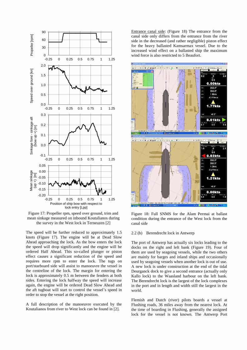
Figure 17: Propeller rpm, speed over ground, trim and
mean sinkage measured on inbound Koutalianos during
the survey in the West lock in Terneuzen [2]
The speed will be further reduced to approximately 1.5
knots (Figure 17). The engine will be at Dead Slow
Ahead approaching the lock. As the bow enters the lock
the speed will drop significantly and the engine will be
ordered Half Ahead. This so-called plunger or piston
effect causes a significant reduction of the speed and
requires more rpm to enter the lock. The tugs on
port/starboard side will assist to manoeuvre the vessel in
the centreline of the lock. The margin for entering the
lock is approximately 0.5 m between the fenders at both
sides. Entering the lock halfway the speed will increase
again, the engine will be ordered Dead Slow Ahead and
the aft tugboat will start to control the vessel’s speed in
order to stop the vessel at the right position.
A full description of the manoeuvre executed by the
Koutalianos from river to West lock can be found in [2].
Entrance canal side: (Figure 18) The entrance from the
canal side only differs from the entrance from the river
side in the decreased (and rather negligible) piston effect
for the heavy ballasted Kamsarmax vessel. Due to the
increased wind effect on a ballasted ship the maximum
wind force is also restricted to 5 Beaufort.
Figure 18: Full SNMS for the Alam Permai at ballast
condition during the entrance of the West lock from the
canal side
2.2 (b) Berendrecht lock in Antwerp
The port of Antwerp has actually six locks leading to the
docks on the right and left bank (Figure 19). Four of
them are used by seagoing vessels, while the two others
are mainly for barges and inland ships and occasionally
used by seagoing vessels when another lock is out of use.
A new lock is under construction at the end of the tidal
Deurganck dock to give a second entrance (actually only
Kallo lock) to the Waasland harbour on the left bank.
The Berendrecht lock is the largest of the lock complexes
in the port and in length and width still the largest in the
world.
Flemish and Dutch (river) pilots boards a vessel at
Flushing roads, 36 miles away from the nearest lock. At
the time of boarding in Flushing, generally the assigned
lock for the vessel is not known. The Antwerp Port
0
30
60
90
-0.25 0 0.25 0.5 0.75 1 1.25
Pro
pelle
r [r
pm
]
0.0
0.5
1.0
1.5
2.0
-0.25 0 0.25 0.5 0.75 1 1.25
Speed o
ver
gro
und [
kn]
-0.1
0.0
0.1
0.2
0.3
-0.25 0 0.25 0.5 0.75 1 1.25
Sin
ka
ge
fo
re -
sin
ka
ge
aft
(bo
w u
p +
) [m
]
-0.20
-0.15
-0.10
-0.05
0.00
0.05
-0.25 0 0.25 0.5 0.75 1 1.25
Mean s
inkage
(up +
) [m
]
Position of ship bow with respect tolock entry [Lpp]

Coordinator is monitoring the incoming vessels and
assigns them a lock based on various criteria such as size,
draft, destination in the docks and availability of the
locks.
While underway, the pilot is informed about the assigned
lock, his turn into the lock, the mooring side and the
approximate time the lock will be ready. This planning is
affecting the sailing on the river taking into account for
example the reduced ship’s speed for matching the
arrival at and the availability of the lock.
Slowing down means that wind and current have more
impact on the vessel’s track and implicates that other
ships destined for a lock upwards the river sometimes
have to overtake.
Figure 19: Lock complexes at the port of Antwerp
(Belgium) with the Berendrecht lock the largest lock
anno 2013 [8]
With the enlargement of ship sizes (length, beam as well
as draft) in the last decade (growing to ULCS with
lengths up to 400 m) overtaking or being overtaken must
be closely controlled as only certain spots on the river
admit this time-consuming and difficult manoeuvre
which has been examined by real-time simulation tests.
Construction (Figure 20)
Figure 20: Berendrecht - Zandvliet lock complex
The Berendrecht lock, built in 1989, connects the
Western Scheldt (river side) with the Canal dock B2
(dock side) and has a length of 500 m, a width of 68 m
and a depth of -13.58 m TAW (Tweede Algemene
Waterpassing, a reference height for infrastructure in
Belgium) or -12.89 LAT which means that deep drafted
ships can only enter thanks to the tidal level. The new
lock at the end of Deurganckdock will have the same
horizontal dimensions but a depth of -17.80 m TAW.
From the river side the lock is mostly approached from
the north while turning from the river with tidal current
to the entrance of the lock. From the dock side with a
mean canal level of 4.25 m TAW (depth at lock sill is
thus 17.83 m) a turning manoeuvre from and to the canal
dock B2 (south of the lock) is required so that at both
sides the approach area is only over a short distance in
line with the lock axis requiring important tug assistance.
The corners of the Berendrecht lock are equipped with
wheel fenders to protect the lock construction and the
ship’s hull during contact.
Figure 21: Entrance of the Berendrecht lock from the
river side during a simulation run with a 380 m
containership (beam 51.6 m, draft 13.1 m) at N 6 Bft and
one 45 ton fore tug and two 60 ton aft tugs
Figure 22: Entrance of a 366 m Ultra Large Container
Ship in the Berendrecht lock at the port of Antwerp
Manoeuvre
Entrance river side (Figure 21 and 22): Although a
planning is made, the availability of the lock on arrival
can be uncertain. Mostly ships are scheduled to depart

from the same lock the arriving vessel is heading to.
Hence, the time the lock will be ready merely depends on
the time the departing ships are moored into the lock.
Delay of the departing vessels means waiting in front of
the lock and finding a place where the vessel can be kept
in position, countering wind and current and sparing
enough room for the departing vessels to safely leave the
lock. Sometimes tugs are scheduled to take out the
departing vessels first and later serve the arriving vessel.
Figure 23: Entrance of the Berendrecht lock from the
dock side during a simulation run with a 380 m
containership (beam 51.6 m, draft 13.1 m) at NE 6 Bft
and three 55 ton tugs
Although a distinction can generally be made for a lock
entrance during flood or ebb tide, no single lock has the
same approach pattern. When the ULCS started to call to
Antwerp (more specific the Berendrecht lock) the
pilotage decided not only to make a tidal window to cope
with the draft of the vessel but also a current window was
determined to avoid a lock entrance at strong ebb tides.
Thanks to the learning process on the simulator these
ULCS are actually entering Berendrecht lock at any tide,
with two pilots on board for ships with length up to
300 m.
For the ULCS with large lateral windage area the
maximum wind condition had to be reduced. The wind
limitations for ULCS can be summarised as:
for a ship length from 300 to 340 m no
limitations;
for a ship length from 340 to 360 m, maximum
7 Bft;
for a ship length larger than 360 m, maximum 5
Bft although for the Deurganck dock (no lock
entrance) a higher wind force of 6 Bft can be
maintained for an inbound and 7 Bft for an
outbound manoeuvre.
Although ahead or following wind directions during a
lock approach are more favourable, the orientation of the
approach channel at both sides of the Berendrecht lock
does not accept higher values for the maximum wind
force.
The tug assistance for a manoeuvre with a 366 m
container ship to the Berendrecht lock is composed of:
Inbound: two 60 ton tugs aft and one 45 or 60
ton fore; for strong winds from south or north
the tug assistance can be increased with an
additional 45 or 60 ton fore; the tugs pull with
the aft tugs fastened at starboard or port side
while the fore tug uses the centre lead hawser.
Outbound: one 60 ton tug center lead aft and
one 45 or 60 ton tug center lead fore. At
minimal wind force the fore tug can be omitted
in favour of the bow thruster.
The bollard pull of the tug fleet in the Flemish harbours
is increasing with some 80 ton tugs available so that the
tug configuration nowadays changes compared to the
configuration used during the simulation studies in
Figure 21 and Figure 23. The tugs start their fastening
procedure about two miles from the Berendrecht lock.
Entrance dock side (Figure 23): The approach of the
Berendrecht lock from the dock side is planned in the
same way and suffers from the same problems in
manoeuvring space (except the tidal current) as at the
river side. After the use of Full SNMS by the river pilots
operating on the Western Scheldt to the port of Antwerp
the dock pilots also introduced the personal pilot units as
Full SNMS to ensure safe manoeuvring.
At the dock side an ULCS has to approach right in front
of the lock after turning from the canal B2 dock, as it is
impossible for such ship to enter the lock from another
angle. If these ships encounter strong winds (more than 5
Bft), the ship’s bow has to be kept to the wind in order to
avoid damages. In case of southern or northern winds
exceed 6 Bft, entering the lock with an ULCS should be
avoided, because of the tugs (especially the fore tug) not
being able to pull full power in the approach of and in the
lock itself.
When leaving the lock to the docks the vessel speed must
be strictly controlled so that the turning manoeuvre from
the lock to the canal B2 dock can be executed safely with
enough reserve to other ships in the docks.
At the dock side, the tug configuration consists of Voith-
Schneider tugs. For ships of 366m and more the use of at
least two tugs is compulsory. In most cases two tugs
with a bollard pull of 50 tons will be provided, if
required this number will be increased to three or four.
3. LOCK EFFECTS DESCRIPTION
The ship-lock combinations described in chapter 2 are
characterised by a large blockage factor, i.e. the ratio of
the ship’s section to the lock section, giving an increased
effect of the hydrodynamic forces while approaching and
leaving the lock. Although the lock effects are specific
for each lock, a description will be based on the practical
information from the four geographically spread locks in
Belgium, The Netherlands, France and Panama.
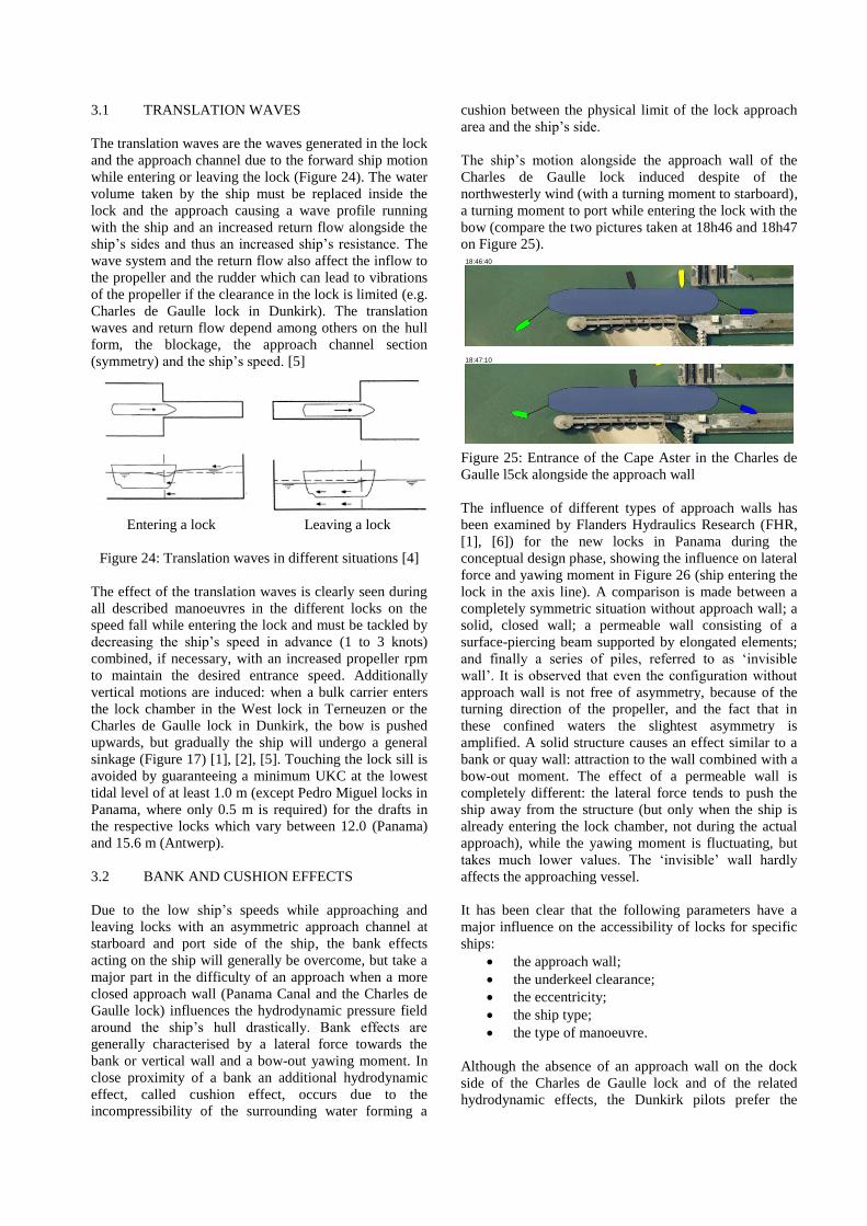
3.1 TRANSLATION WAVES
The translation waves are the waves generated in the lock
and the approach channel due to the forward ship motion
while entering or leaving the lock (Figure 24). The water
volume taken by the ship must be replaced inside the
lock and the approach causing a wave profile running
with the ship and an increased return flow alongside the
ship’s sides and thus an increased ship’s resistance. The
wave system and the return flow also affect the inflow to
the propeller and the rudder which can lead to vibrations
of the propeller if the clearance in the lock is limited (e.g.
Charles de Gaulle lock in Dunkirk). The translation
waves and return flow depend among others on the hull
form, the blockage, the approach channel section
(symmetry) and the ship’s speed. [5]
Entering a lock Leaving a lock
Figure 24: Translation waves in different situations [4]
The effect of the translation waves is clearly seen during
all described manoeuvres in the different locks on the
speed fall while entering the lock and must be tackled by
decreasing the ship’s speed in advance (1 to 3 knots)
combined, if necessary, with an increased propeller rpm
to maintain the desired entrance speed. Additionally
vertical motions are induced: when a bulk carrier enters
the lock chamber in the West lock in Terneuzen or the
Charles de Gaulle lock in Dunkirk, the bow is pushed
upwards, but gradually the ship will undergo a general
sinkage (Figure 17) [1], [2], [5]. Touching the lock sill is
avoided by guaranteeing a minimum UKC at the lowest
tidal level of at least 1.0 m (except Pedro Miguel locks in
Panama, where only 0.5 m is required) for the drafts in
the respective locks which vary between 12.0 (Panama)
and 15.6 m (Antwerp).
3.2 BANK AND CUSHION EFFECTS
Due to the low ship’s speeds while approaching and
leaving locks with an asymmetric approach channel at
starboard and port side of the ship, the bank effects
acting on the ship will generally be overcome, but take a
major part in the difficulty of an approach when a more
closed approach wall (Panama Canal and the Charles de
Gaulle lock) influences the hydrodynamic pressure field
around the ship’s hull drastically. Bank effects are
generally characterised by a lateral force towards the
bank or vertical wall and a bow-out yawing moment. In
close proximity of a bank an additional hydrodynamic
effect, called cushion effect, occurs due to the
incompressibility of the surrounding water forming a
cushion between the physical limit of the lock approach
area and the ship’s side.
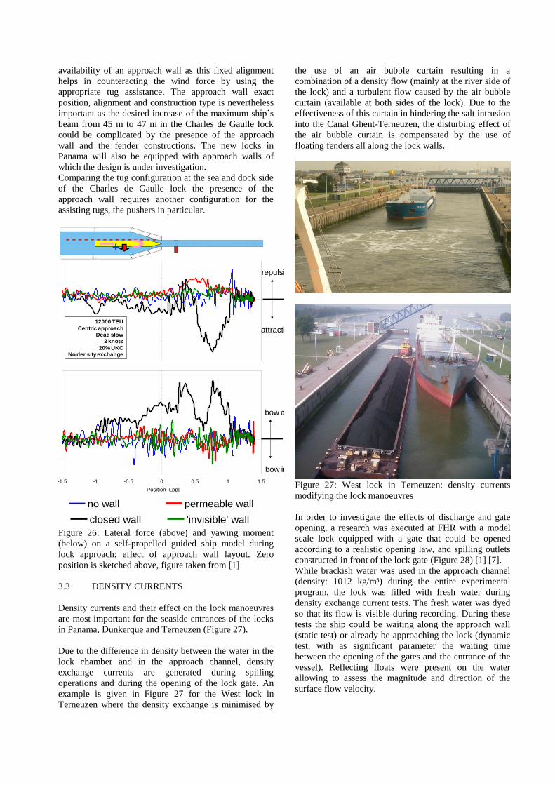
The ship’s motion alongside the approach wall of the
Charles de Gaulle lock induced despite of the
northwesterly wind (with a turning moment to starboard),
a turning moment to port while entering the lock with the
bow (compare the two pictures taken at 18h46 and 18h47
on Figure 25).
Figure 25: Entrance of the Cape Aster in the Charles de
Gaulle l5ck alongside the approach wall
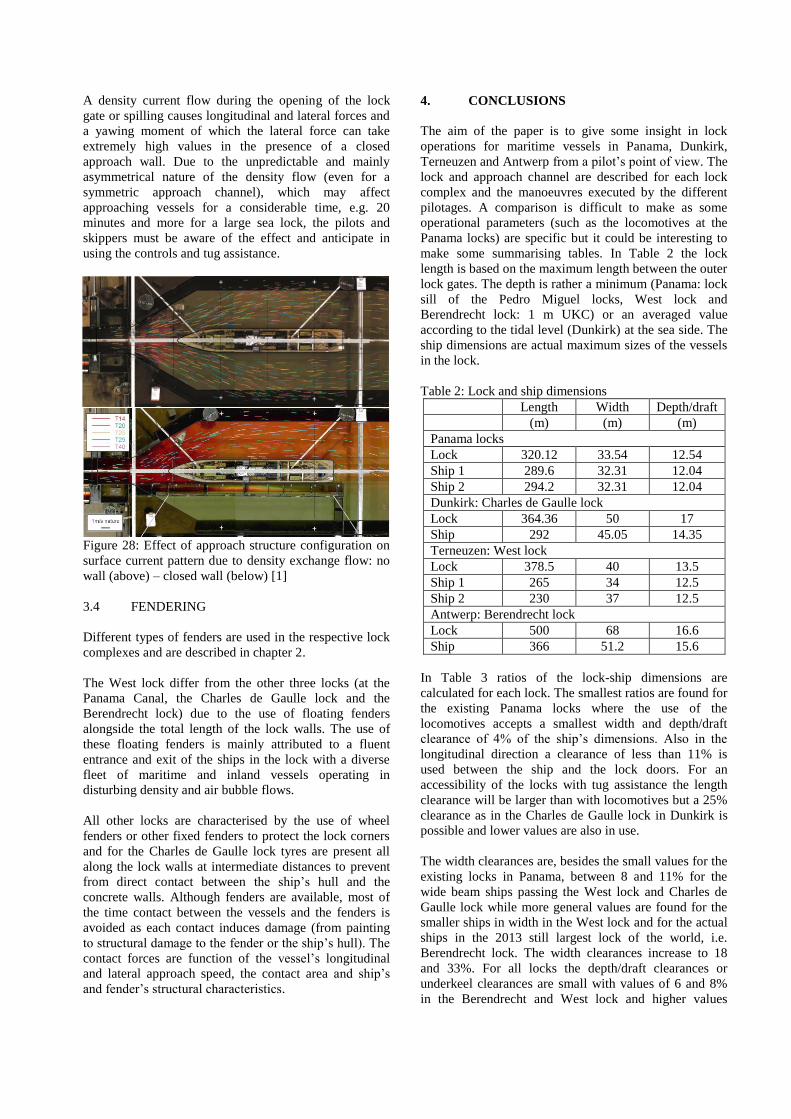
The influence of different types of approach walls has
been examined by Flanders Hydraulics Research (FHR,
[1], [6]) for the new locks in Panama during the
conceptual design phase, showing the influence on lateral
force and yawing moment in Figure 26 (ship entering the
lock in the axis line). A comparison is made between a
completely symmetric situation without approach wall; a
solid, closed wall; a permeable wall consisting of a
surface-piercing beam supported by elongated elements;
and finally a series of piles, referred to as ‘invisible
wall’. It is observed that even the configuration without
approach wall is not free of asymmetry, because of the
turning direction of the propeller, and the fact that in
these confined waters the slightest asymmetry is
amplified. A solid structure causes an effect similar to a
bank or quay wall: attraction to the wall combined with a
bow-out moment. The effect of a permeable wall is
completely different: the lateral force tends to push the
ship away from the structure (but only when the ship is
already entering the lock chamber, not during the actual
approach), while the yawing moment is fluctuating, but
takes much lower values. The ‘invisible’ wall hardly
affects the approaching vessel.
It has been clear that the following parameters have a
major influence on the accessibility of locks for specific
ships:
the approach wall;
the underkeel clearance;
the eccentricity;
the ship type;
the type of manoeuvre.
Although the absence of an approach wall on the dock
side of the Charles de Gaulle lock and of the related
hydrodynamic effects, the Dunkirk pilots prefer the
18:46:40
18:47:10
availability of an approach wall as this fixed alignment
helps in counteracting the wind force by using the
appropriate tug assistance. The approach wall exact
position, alignment and construction type is nevertheless
important as the desired increase of the maximum ship’s
beam from 45 m to 47 m in the Charles de Gaulle lock
could be complicated by the presence of the approach
wall and the fender constructions. The new locks in
Panama will also be equipped with approach walls of
which the design is under investigation.
Comparing the tug configuration at the sea and dock side
of the Charles de Gaulle lock the presence of the
approach wall requires another configuration for the
assisting tugs, the pushers in particular.
Figure 26: Lateral force (above) and yawing moment
(below) on a self-propelled guided ship model during
lock approach: effect of approach wall layout. Zero
position is sketched above, figure taken from [1]
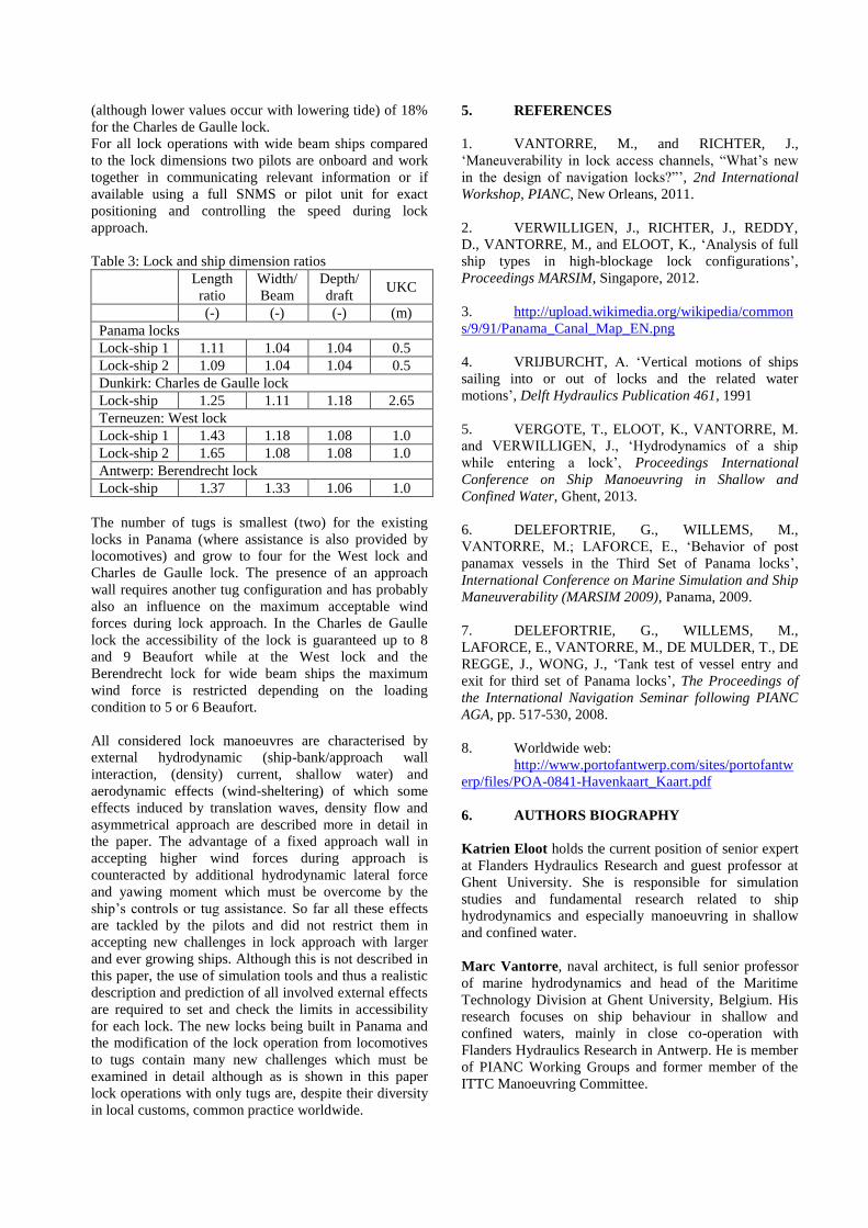
3.3 DENSITY CURRENTS
Density currents and their effect on the lock manoeuvres
are most important for the seaside entrances of the locks
in Panama, Dunkerque and Terneuzen (Figure 27).
Due to the difference in density between the water in the
lock chamber and in the approach channel, density
exchange currents are generated during spilling
operations and during the opening of the lock gate. An
example is given in Figure 27 for the West lock in
Terneuzen where the density exchange is minimised by
the use of an air bubble curtain resulting in a
combination of a density flow (mainly at the river side of
the lock) and a turbulent flow caused by the air bubble
curtain (available at both sides of the lock). Due to the
effectiveness of this curtain in hindering the salt intrusion
into the Canal Ghent-Terneuzen, the disturbing effect of
the air bubble curtain is compensated by the use of
floating fenders all along the lock walls.
Figure 27: West lock in Terneuzen: density currents
modifying the lock manoeuvres
In order to investigate the effects of discharge and gate
opening, a research was executed at FHR with a model
scale lock equipped with a gate that could be opened
according to a realistic opening law, and spilling outlets
constructed in front of the lock gate (Figure 28) [1] [7].
While brackish water was used in the approach channel
(density: 1012 kg/m³) during the entire experimental
program, the lock was filled with fresh water during
density exchange current tests. The fresh water was dyed
so that its flow is visible during recording. During these
tests the ship could be waiting along the approach wall
(static test) or already be approaching the lock (dynamic
test, with as significant parameter the waiting time
between the opening of the gates and the entrance of the
vessel). Reflecting floats were present on the water
allowing to assess the magnitude and direction of the
surface flow velocity.
-180
-120
-60
0
60
120
-1.5 -1 -0.5 0 0.5 1 1.5
Position [Lpp]
Late
ral fo
rce [
ton]
no wall permeable wall closed wall 'invisible' wall
repulsion
attraction
+
12000 TEU
Centric approachDead slow
2 knots
20% UKCNo density exchange
-10000
-5000
0
5000
10000
15000
20000
-1.5 -1 -0.5 0 0.5 1 1.5
Position [Lpp]
Ya
win
g m
om
en
t [t
on
.m]
no wall permeable wall closed wall 'invisible' wall
bow out
bow in
-10000
-5000
0
5000
10000
15000
20000
-1.5 -1 -0.5 0 0.5 1 1.5
Position [Lpp]
Ya
win
g m
om
en
t [t
on
.m]
no wall permeable wall closed wall 'invisible' wall
bow out
bow in -10000
-5000
0
5000
10000
15000
20000
-1.5 -1 -0.5 0 0.5 1 1.5
Position [Lpp]
Ya
win
g m
om
en
t [t
on
.m]
no wall permeable wall closed wall 'invisible' wall
bow out
bow in
A density current flow during the opening of the lock
gate or spilling causes longitudinal and lateral forces and
a yawing moment of which the lateral force can take
extremely high values in the presence of a closed
approach wall. Due to the unpredictable and mainly
asymmetrical nature of the density flow (even for a
symmetric approach channel), which may affect
approaching vessels for a considerable time, e.g. 20
minutes and more for a large sea lock, the pilots and
skippers must be aware of the effect and anticipate in
using the controls and tug assistance.
Figure 28: Effect of approach structure configuration on
surface current pattern due to density exchange flow: no
wall (above) – closed wall (below) [1]
3.4 FENDERING
Different types of fenders are used in the respective lock
complexes and are described in chapter 2.
The West lock differ from the other three locks (at the
Panama Canal, the Charles de Gaulle lock and the
Berendrecht lock) due to the use of floating fenders
alongside the total length of the lock walls. The use of
these floating fenders is mainly attributed to a fluent
entrance and exit of the ships in the lock with a diverse
fleet of maritime and inland vessels operating in
disturbing density and air bubble flows.
All other locks are characterised by the use of wheel
fenders or other fixed fenders to protect the lock corners
and for the Charles de Gaulle lock tyres are present all
along the lock walls at intermediate distances to prevent
from direct contact between the ship’s hull and the
concrete walls. Although fenders are available, most of
the time contact between the vessels and the fenders is
avoided as each contact induces damage (from painting
to structural damage to the fender or the ship’s hull). The
contact forces are function of the vessel’s longitudinal
and lateral approach speed, the contact area and ship’s
and fender’s structural characteristics.
4. CONCLUSIONS
The aim of the paper is to give some insight in lock
operations for maritime vessels in Panama, Dunkirk,
Terneuzen and Antwerp from a pilot’s point of view. The
lock and approach channel are described for each lock
complex and the manoeuvres executed by the different
pilotages. A comparison is difficult to make as some
operational parameters (such as the locomotives at the
Panama locks) are specific but it could be interesting to
make some summarising tables. In Table 2 the lock
length is based on the maximum length between the outer
lock gates. The depth is rather a minimum (Panama: lock
sill of the Pedro Miguel locks, West lock and
Berendrecht lock: 1 m UKC) or an averaged value
according to the tidal level (Dunkirk) at the sea side. The
ship dimensions are actual maximum sizes of the vessels
in the lock.
Table 2: Lock and ship dimensions
Length Width Depth/draft
(m) (m) (m)
Panama locks
Lock 320.12 33.54 12.54
Ship 1 289.6 32.31 12.04
Ship 2 294.2 32.31 12.04
Dunkirk: Charles de Gaulle lock
Lock 364.36 50 17
Ship 292 45.05 14.35
Terneuzen: West lock
Lock 378.5 40 13.5
Ship 1 265 34 12.5
Ship 2 230 37 12.5
Antwerp: Berendrecht lock
Lock 500 68 16.6
Ship 366 51.2 15.6
In Table 3 ratios of the lock-ship dimensions are
calculated for each lock. The smallest ratios are found for
the existing Panama locks where the use of the
locomotives accepts a smallest width and depth/draft
clearance of 4% of the ship’s dimensions. Also in the
longitudinal direction a clearance of less than 11% is
used between the ship and the lock doors. For an
accessibility of the locks with tug assistance the length
clearance will be larger than with locomotives but a 25%
clearance as in the Charles de Gaulle lock in Dunkirk is
possible and lower values are also in use.
The width clearances are, besides the small values for the
existing locks in Panama, between 8 and 11% for the
wide beam ships passing the West lock and Charles de
Gaulle lock while more general values are found for the
smaller ships in width in the West lock and for the actual
ships in the 2013 still largest lock of the world, i.e.
Berendrecht lock. The width clearances increase to 18
and 33%. For all locks the depth/draft clearances or
underkeel clearances are small with values of 6 and 8%
in the Berendrecht and West lock and higher values
(although lower values occur with lowering tide) of 18%
for the Charles de Gaulle lock.
For all lock operations with wide beam ships compared
to the lock dimensions two pilots are onboard and work
together in communicating relevant information or if
available using a full SNMS or pilot unit for exact
positioning and controlling the speed during lock
approach.
Table 3: Lock and ship dimension ratios
Length
ratio
Width/
Beam
Depth/
draft UKC
(-) (-) (-) (m)
Panama locks
Lock-ship 1 1.11 1.04 1.04 0.5
Lock-ship 2 1.09 1.04 1.04 0.5
Dunkirk: Charles de Gaulle lock
Lock-ship 1.25 1.11 1.18 2.65
Terneuzen: West lock
Lock-ship 1 1.43 1.18 1.08 1.0
Lock-ship 2 1.65 1.08 1.08 1.0
Antwerp: Berendrecht lock
Lock-ship 1.37 1.33 1.06 1.0
The number of tugs is smallest (two) for the existing
locks in Panama (where assistance is also provided by
locomotives) and grow to four for the West lock and
Charles de Gaulle lock. The presence of an approach
wall requires another tug configuration and has probably
also an influence on the maximum acceptable wind
forces during lock approach. In the Charles de Gaulle
lock the accessibility of the lock is guaranteed up to 8
and 9 Beaufort while at the West lock and the
Berendrecht lock for wide beam ships the maximum
wind force is restricted depending on the loading
condition to 5 or 6 Beaufort.
All considered lock manoeuvres are characterised by
external hydrodynamic (ship-bank/approach wall
interaction, (density) current, shallow water) and
aerodynamic effects (wind-sheltering) of which some
effects induced by translation waves, density flow and
asymmetrical approach are described more in detail in
the paper. The advantage of a fixed approach wall in
accepting higher wind forces during approach is
counteracted by additional hydrodynamic lateral force
and yawing moment which must be overcome by the
ship’s controls or tug assistance. So far all these effects
are tackled by the pilots and did not restrict them in
accepting new challenges in lock approach with larger
and ever growing ships. Although this is not described in
this paper, the use of simulation tools and thus a realistic
description and prediction of all involved external effects
are required to set and check the limits in accessibility
for each lock. The new locks being built in Panama and
the modification of the lock operation from locomotives
to tugs contain many new challenges which must be
examined in detail although as is shown in this paper
lock operations with only tugs are, despite their diversity
in local customs, common practice worldwide.
5. REFERENCES
1. VANTORRE, M., and RICHTER, J.,
‘Maneuverability in lock access channels, “What’s new
in the design of navigation locks?”’, 2nd International
Workshop, PIANC, New Orleans, 2011.
2. VERWILLIGEN, J., RICHTER, J., REDDY,
D., VANTORRE, M., and ELOOT, K., ‘Analysis of full
ship types in high-blockage lock configurations’,
Proceedings MARSIM, Singapore, 2012.
3. http://upload.wikimedia.org/wikipedia/common
s/9/91/Panama_Canal_Map_EN.png
4. VRIJBURCHT, A. ‘Vertical motions of ships
sailing into or out of locks and the related water
motions’, Delft Hydraulics Publication 461, 1991
5. VERGOTE, T., ELOOT, K., VANTORRE, M.
and VERWILLIGEN, J., ‘Hydrodynamics of a ship
while entering a lock’, Proceedings International
Conference on Ship Manoeuvring in Shallow and
Confined Water, Ghent, 2013.
6. DELEFORTRIE, G., WILLEMS, M.,
VANTORRE, M.; LAFORCE, E., ‘Behavior of post
panamax vessels in the Third Set of Panama locks’,
International Conference on Marine Simulation and Ship
Maneuverability (MARSIM 2009), Panama, 2009.
7. DELEFORTRIE, G., WILLEMS, M.,
LAFORCE, E., VANTORRE, M., DE MULDER, T., DE
REGGE, J., WONG, J., ‘Tank test of vessel entry and
exit for third set of Panama locks’, The Proceedings of
the International Navigation Seminar following PIANC
AGA, pp. 517-530, 2008.
8. Worldwide web:
http://www.portofantwerp.com/sites/portofantw
erp/files/POA-0841-Havenkaart_Kaart.pdf
6. AUTHORS BIOGRAPHY
Katrien Eloot holds the current position of senior expert
at Flanders Hydraulics Research and guest professor at
Ghent University. She is responsible for simulation
studies and fundamental research related to ship
hydrodynamics and especially manoeuvring in shallow
and confined water.
Marc Vantorre, naval architect, is full senior professor
of marine hydrodynamics and head of the Maritime
Technology Division at Ghent University, Belgium. His
research focuses on ship behaviour in shallow and
confined waters, mainly in close co-operation with
Flanders Hydraulics Research in Antwerp. He is member
of PIANC Working Groups and former member of the
ITTC Manoeuvring Committee.

Jeroen Verwilligen holds the current position of nautical
researcher at Flanders Hydraulics Research. He is
experienced with simulation studies and full-scale
measurements on several vessels to Flemish Harbours.
He is responsible for initiating CFD research at FHR.
Dirk Bus is river pilot (operating on the Western
Scheldt) of the Flemish Pilotage in Flanders, Belgium.
Rudi Cleeren is river pilot (operating on the Western
Scheldt) of the Flemish Pilotage in Flanders, Belgium.
Erwin Gheyle is canal pilot (operating on the entrance to
the Terneuzen complex and the canal Ghent-Terneuzen)
of the Flemish Pilotage in Flanders, Belgium.
Eric Vèche is pilot at the Station de Pilotage de Dunkirk,
France.
Eugene Heugen is pilot at the Dutch Pilotage, the
Netherlands.
Jos van Drongelen is pilot at the Dutch Pilotage, the
Netherlands.
Rainiero Salas is Panama Canal Pilot, Panama.
Ronny Detienne is director of the pilotage CVBA
BRABO, operating in the docks of the Port of Antwerp,
Belgium.


