Embed Size (px)
Citation preview
Location Tracking System For Mining Industry
OpenCon Systems Inc. 371 Hoes Lane, Piscataway, New Jersey 08854 Phone: 732 463 3131 Fax: 732 463 3557 www.opencon.com
Copyrigh © 2009. All rights reserved.l
OCS Micro-OLT System
Bandwidth limitation in the last mile of a communications network has always been a major challenge in delivering multimedia service to residential and B2B customers. Gigabit-capable Passive Optical Network (GPON) technology solves the last mile problem by providing up to 2.4 Gbps downstream and 1.2 Gbps upstream bandwidth for user traffic. A GPON system normally consists of an OLT system and a number of ONT/ONU devices. A GPON OLT system is typically installed in the Carrier’s Central Office (CO) which aggregates the traffic from all the connected ONTs/ONUs. Micro-OLT (M-OLT) is a smaller and portable OLT, which is typically mounted on a street furniture or building façade. This white paper summarizes the merit of an outdoor Micro-OLT and highlights the variety of applications, which a Micro-OLT based GPON system can be applicable. Read more …
OpenCon Systems Inc. 371 Hoes Lane, Piscataway, New Jersey 08854 Phone: 732 463 3131 Fax: 732 463 3557 www.opencon.com
Copyright © 2013. All rights reserved.
Page 1 Copyright © 2013. OpenCon Systems Inc. All rights reserved.
OCS-WP-498
1 Introduction
The copper-based access network has long been the bottleneck in delivering multimedia service (or so called triple play services), which includes Voice, Video and Internet Data services, to the end-users. The existing copper (twisted pair and coaxial cable) infrastructure can hardly meet the requirements for triple play services in the 21st century. The telecom service providers strive to change the situation by adopting optical fiber based last mile transport technology such as FTTH, FTTB and FTTC. One of the popular choices of technology by the service providers for the FTTx transport is the Gigabit-capable Passive Optic Network (GPON). A GPON network consists of a number of Optical Network Terminals/Units (ONT/ONU) which are typically installed at the subscriber’s premises and a controller, called the Optical Line Terminal (OLT), installed in the Central Office. A centralized GPON OLT system can aggregate user traffic from a large number of ONTs/ONUs. However, this configuration implies that a large number of optical fibers may have to be installed in the feeder network. To minimize the number of optical fibers in the feeder network, many applications need a smaller, portable OLT systems which can be mounted on a street furniture or building façade and connected the metro or core network via a high speed Ethernet or xWDM RING. OpenCon Systems Inc. (OCS) Micro-OLT (M-OLT) is such a system1.
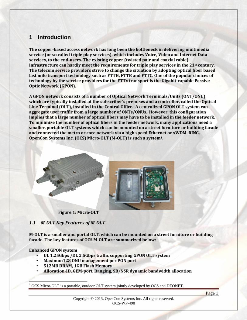
Figure 1: Micro-OLT
1.1 M-OLT Key Features of M-OLT
M-OLT is a smaller and portal OLT, which can be mounted on a street furniture or building façade. The key features of OCS M-OLT are summarized below: Enhanced GPON system
• UL 1.25Gbps /DL 2.5Gbps traffic supporting GPON OLT system • Maximun128 ONU management per PON port • 512MB DRAM, 1GB Flash Memory • Allocation-ID, GEM-port, Ranging, SR/NSR dynamic bandwidth allocation
1 OCS Micro-OLT is a portable, outdoor OLT system jointly developed by OCS and DEONET.
Page 2 Copyright © 2013. OpenCon Systems Inc. All rights reserved.
OCS-WP-498
• SF(Signal Failure), SD(Signal Degrade), LoF(Loss of Frame), LoS(Loss of Signal), Rogue-ONT monitoring features
• AES(Advanced Encryption Standard) , PM(Performance Monitoring), ONU remote control and management features
• Service specific QoS support with multi T-CONT features • MAC Limit • AES encryption • Abnormal traffic blocking • High speed ONU upgrade features with extended message set
Physical Interface • 4 port GPON • 4 port 1000Base-X Gigabit Ethernet • RJ45 Console port
Switching features • 32K MAC, 4,096 Active VLANs • 802.1Q VLAN Tagging, 802.1p, 8 Level priority queues • SPQ(Strict Priority Queuing), DWRR(Deficit Weighted Round Robin), SPQ+DWRR • IGMP snooping v1, v2 and IGMP limit/filtering • 1M unit ingress and egress rate limiting features • Spanning Tree Protocol(STP, RSTP) • MTU 9K byte support
Operation and management features • SSH(Security Shell), SNMP, telnet, syslog • RADIUS, TACACS • Operation status monitoring through external LED • Remote upgrade • Wireless console(Bluetooth)
Page 3 Copyright © 2013. OpenCon Systems Inc. All rights reserved.
OCS-WP-498
2 Terms and Abbreviations API Application Programming Interface CAPEX Capital Expenditure CMTS Cable Modem Termination System CPRI Common Public Radio Interface FTTH Fiber to The home FTTB Fiber to The Building FTTC Fiber to The Curb GPON Gigabit-capable Passive Optical Network HFC Hybrid Fiber Coaxial M-OLT Micro OLT OPEX Operating Expenditure OLT Optical Line Terminal ONT Optical Network Terminal ONU Optical Network Unit PON Passive Optical Network RRH Remote Radio Head
Page 4 Copyright © 2013. OpenCon Systems Inc. All rights reserved.
OCS-WP-498
3 Applications of M-OLT
3.1 M-OLT for FTTH Networks
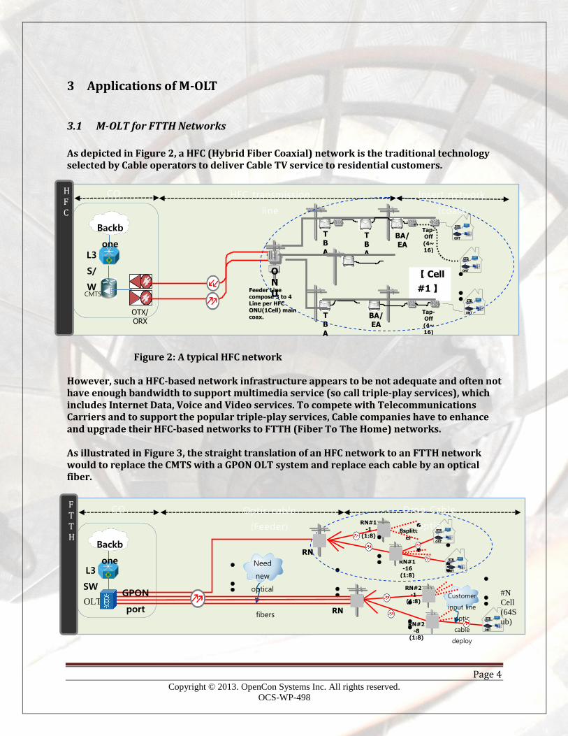
As depicted in Figure 2, a HFC (Hybrid Fiber Coaxial) network is the traditional technology selected by Cable operators to deliver Cable TV service to residential customers. Figure 2: A typical HFC network However, such a HFC-based network infrastructure appears to be not adequate and often not have enough bandwidth to support multimedia service (so call triple-play services), which includes Internet Data, Voice and Video services. To compete with Telecommunications Carriers and to support the popular triple-play services, Cable companies have to enhance and upgrade their HFC-based networks to FTTH (Fiber To The Home) networks. As illustrated in Figure 3, the straight translation of an HFC network to an FTTH network would to replace the CMTS with a GPON OLT system and replace each cable by an optical fiber.
CMTS
L3
S/
W
Backb
one
OTX/ORX
O
NU
TBA
【 Cell
#1 】
TBA
BA/EA
Tap-Off (4~16)
BA/EA
●
● ●
Tap-Off (4~16)
TBA
Feeder Line compose 3 to 4 Line per HFC
ONU(1Cell) main coax.
CO HFC transmission
line
Insert network
(coax)
H F C
RN
RN
RN#2-1
(1:8)
RN#2-8
(1:8)
●
● ●
●
● ●
8splitt
er
Need
new
optical
fibers
Customer
input line
optic
cable
deploy
RN#1-16
(1:8)
●
● ●
●
● ●
●
● ●
Backb
one L3
SW
OLT GPON
port
●
● ●
RN#1-1
(1:8)
#N
Cell (64S
ub)
●
● ●
CO Optic cable
(Feeder)
Drop Cable
(optic)
F T T H
Page 5 Copyright © 2013. OpenCon Systems Inc. All rights reserved.
OCS-WP-498
Figure 3: Straight translation of an HFC network to an FTTH network However, this appear-to-be simple approach has its inherited drawbacks:
To replace the cables in the feeder network by optical fibers requires large number of fibers be installed in the feeder network
The installation of such additional fibers in the feeder network increases the CAPEX and OPEX of operation
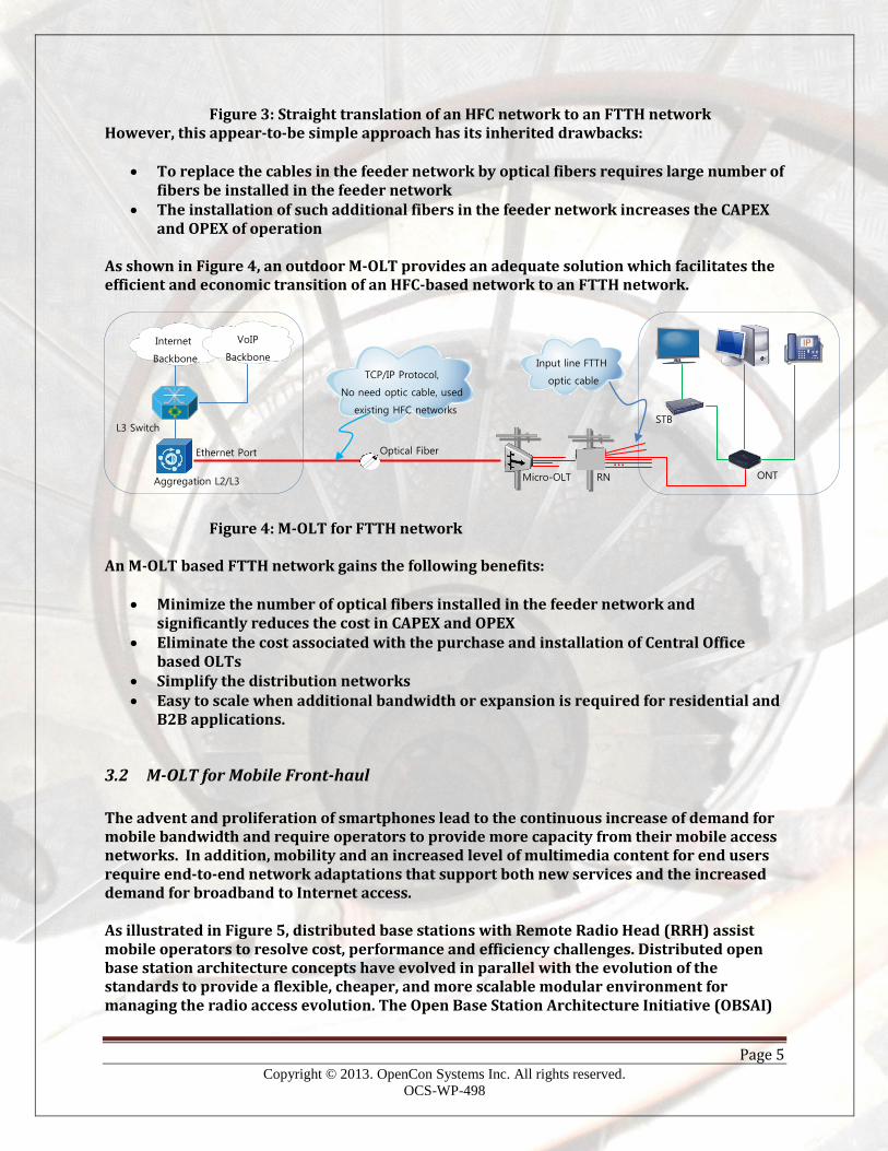
As shown in Figure 4, an outdoor M-OLT provides an adequate solution which facilitates the efficient and economic transition of an HFC-based network to an FTTH network. Figure 4: M-OLT for FTTH network An M-OLT based FTTH network gains the following benefits:
Minimize the number of optical fibers installed in the feeder network and significantly reduces the cost in CAPEX and OPEX
Eliminate the cost associated with the purchase and installation of Central Office based OLTs
Simplify the distribution networks Easy to scale when additional bandwidth or expansion is required for residential and
B2B applications.
3.2 M-OLT for Mobile Front-haul
The advent and proliferation of smartphones lead to the continuous increase of demand for mobile bandwidth and require operators to provide more capacity from their mobile access networks. In addition, mobility and an increased level of multimedia content for end users require end-to-end network adaptations that support both new services and the increased demand for broadband to Internet access. As illustrated in Figure 5, distributed base stations with Remote Radio Head (RRH) assist mobile operators to resolve cost, performance and efficiency challenges. Distributed open base station architecture concepts have evolved in parallel with the evolution of the standards to provide a flexible, cheaper, and more scalable modular environment for managing the radio access evolution. The Open Base Station Architecture Initiative (OBSAI)
Internet
Backbone
L3 Switch
Aggregation L2/L3
Optical Fiber
Micro-OLT RN ONT
STB
VoIP Backbone
…
TCP/IP Protocol, No need optic cable, used
existing HFC networks
Input line FTTH
optic cable
Ethernet Port

Page 6 Copyright © 2013. OpenCon Systems Inc. All rights reserved.
OCS-WP-498
and the Common Public Radio Interface (CPRI) standards introduced the standardized interface between the Base Station server and the remote radio heads (RRHs).
Figure 5: A Distributed base station with RRHs
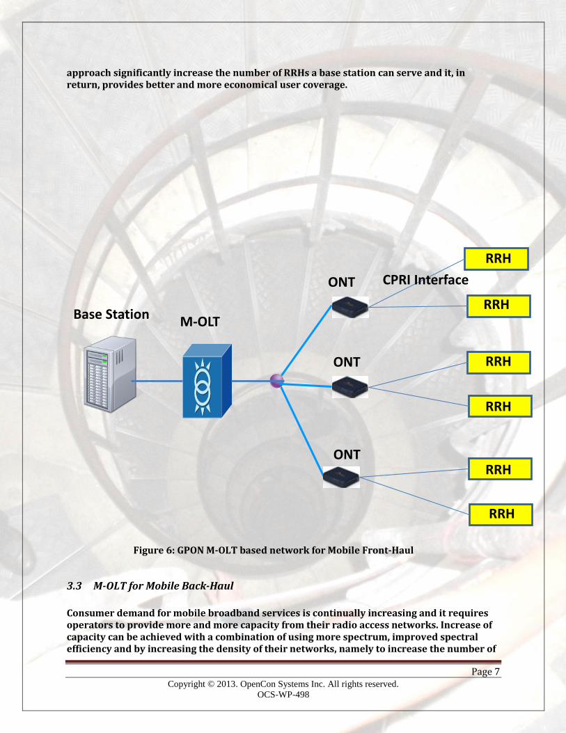
However, when the number of RRHs increases, the base station may have difficulty to accommodate so many RRHs. Consequently, a mobile front-haul network is required to aggregate the traffic from each RRH to the corresponding Base Station. As illustrated in Figure 6, an M-OLT based GPON network can perfectly serve the purpose. Each ONT can support the required CPRI interface to interact with one of more RRHs. The easy to install M-OLT system aggregates the traffic, which includes the user plane data, control and management as well as synchronization signals, to the corresponding base station. This
Remote Radio Head (RRH), Rooftop Mount
Remote Radio Head (RRH), Tower Mount
Base Station Server
External Network
Common Public Radio Interface (CPRI)
Common Public Radio Interface (CPRI)
Page 7 Copyright © 2013. OpenCon Systems Inc. All rights reserved.
OCS-WP-498
approach significantly increase the number of RRHs a base station can serve and it, in return, provides better and more economical user coverage. Figure 6: GPON M-OLT based network for Mobile Front-Haul
3.3 M-OLT for Mobile Back-Haul
Consumer demand for mobile broadband services is continually increasing and it requires operators to provide more and more capacity from their radio access networks. Increase of capacity can be achieved with a combination of using more spectrum, improved spectral efficiency and by increasing the density of their networks, namely to increase the number of
M-OLT
ONT
Base Station
RRH
RRH
RRH
RRH
RRH
RRH
ONT
ONT CPRI Interface
Page 8 Copyright © 2013. OpenCon Systems Inc. All rights reserved.
OCS-WP-498
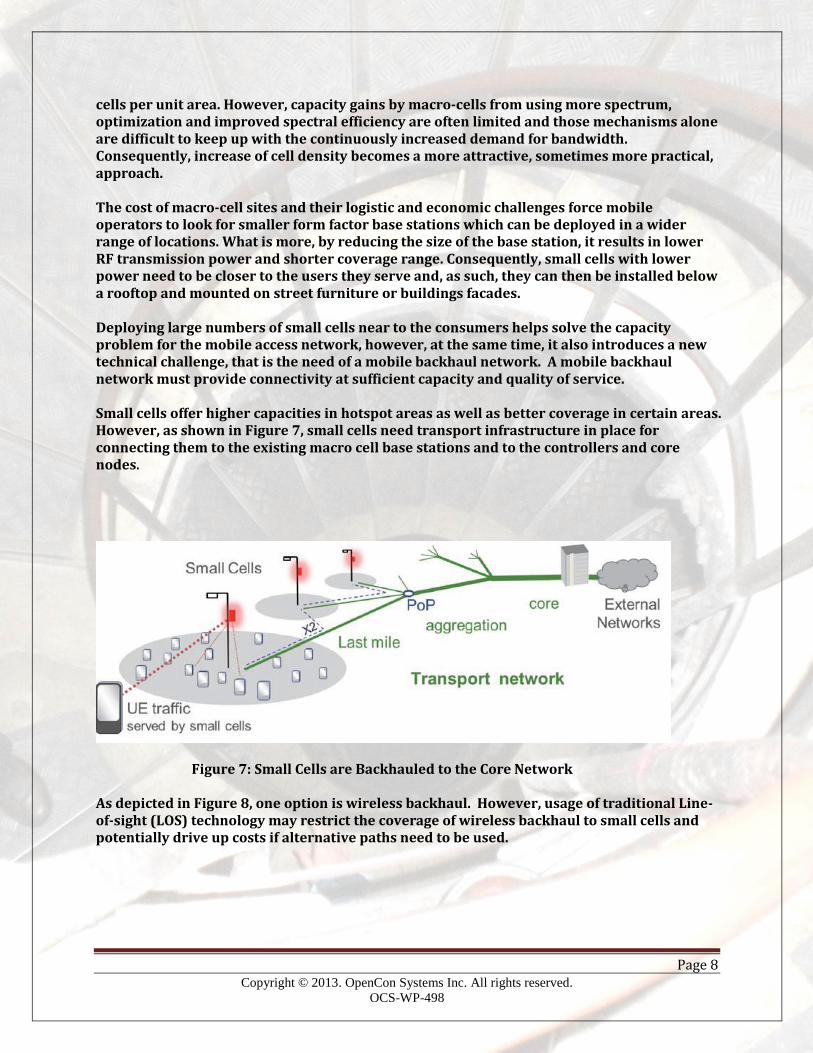
cells per unit area. However, capacity gains by macro-cells from using more spectrum, optimization and improved spectral efficiency are often limited and those mechanisms alone are difficult to keep up with the continuously increased demand for bandwidth. Consequently, increase of cell density becomes a more attractive, sometimes more practical, approach. The cost of macro-cell sites and their logistic and economic challenges force mobile operators to look for smaller form factor base stations which can be deployed in a wider range of locations. What is more, by reducing the size of the base station, it results in lower RF transmission power and shorter coverage range. Consequently, small cells with lower power need to be closer to the users they serve and, as such, they can then be installed below a rooftop and mounted on street furniture or buildings facades. Deploying large numbers of small cells near to the consumers helps solve the capacity problem for the mobile access network, however, at the same time, it also introduces a new technical challenge, that is the need of a mobile backhaul network. A mobile backhaul network must provide connectivity at sufficient capacity and quality of service. Small cells offer higher capacities in hotspot areas as well as better coverage in certain areas. However, as shown in Figure 7, small cells need transport infrastructure in place for connecting them to the existing macro cell base stations and to the controllers and core nodes.
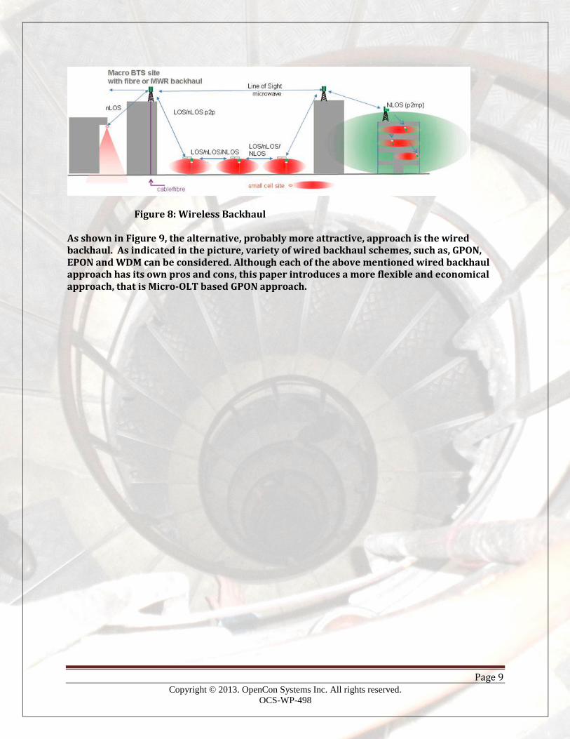
Figure 7: Small Cells are Backhauled to the Core Network As depicted in Figure 8, one option is wireless backhaul. However, usage of traditional Line-of-sight (LOS) technology may restrict the coverage of wireless backhaul to small cells and potentially drive up costs if alternative paths need to be used.
Page 9 Copyright © 2013. OpenCon Systems Inc. All rights reserved.
OCS-WP-498
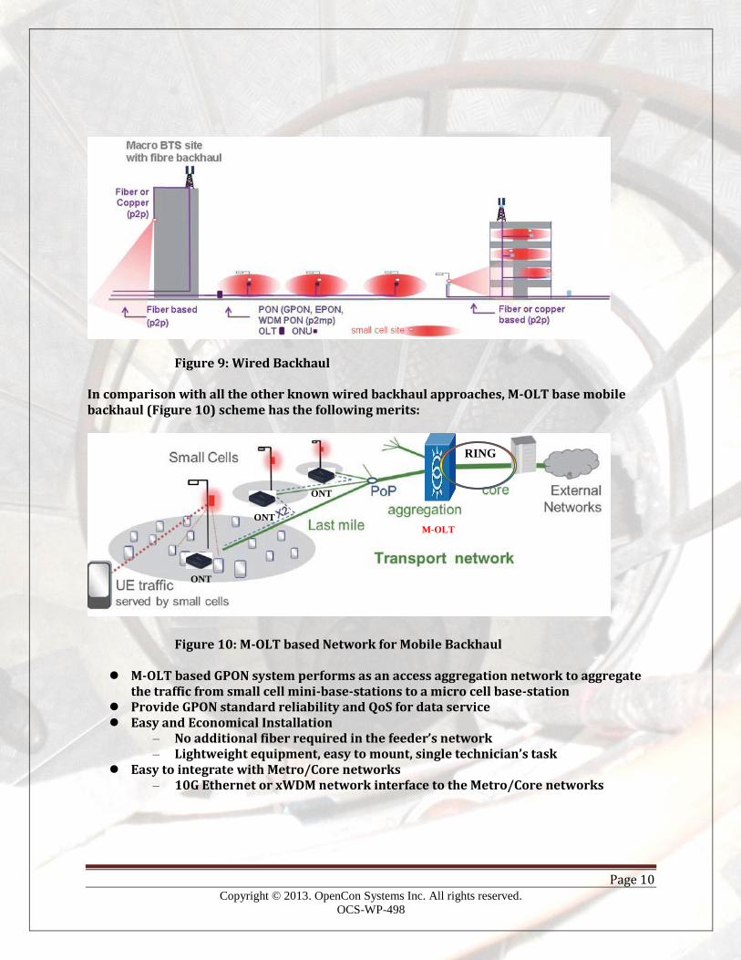
Figure 8: Wireless Backhaul As shown in Figure 9, the alternative, probably more attractive, approach is the wired backhaul. As indicated in the picture, variety of wired backhaul schemes, such as, GPON, EPON and WDM can be considered. Although each of the above mentioned wired backhaul approach has its own pros and cons, this paper introduces a more flexible and economical approach, that is Micro-OLT based GPON approach.
Page 10 Copyright © 2013. OpenCon Systems Inc. All rights reserved.
OCS-WP-498
Figure 9: Wired Backhaul In comparison with all the other known wired backhaul approaches, M-OLT base mobile backhaul (Figure 10) scheme has the following merits: Figure 10: M-OLT based Network for Mobile Backhaul
M-OLT based GPON system performs as an access aggregation network to aggregate the traffic from small cell mini-base-stations to a micro cell base-station
Provide GPON standard reliability and QoS for data service Easy and Economical Installation
– No additional fiber required in the feeder’s network – Lightweight equipment, easy to mount, single technician’s task
Easy to integrate with Metro/Core networks – 10G Ethernet or xWDM network interface to the Metro/Core networks
M-OLT ONT
ONT
ONT
RING
Page 11 Copyright © 2013. OpenCon Systems Inc. All rights reserved.
OCS-WP-498
4 Conclusion One of the biggest impediments of fast GPON roll out is the availability of the inexpensive GPON OLT and ONTs. OCS M-OLT provides a flexible, portable and economical OLT solution which can be installed outdoor, either mounted on a street-furniture and a building façade. Such a portal and flexible infrastructure introduces not only an economical FTTH solution for residential and B2B customers, it also inspires a variety of new applications which includes various broadband and mobile backhaul and front-haul applications.