Embed Size (px)
Citation preview

Strong localization of ionization in high power impulse magnetron sputtering:
An enabling route to niobium plasma coatings of SRF cavities
André Anders, Pavel Ni, Christian Hornschuch, Rueben Mendelsberg, and Joseph Wallig
Lawrence Berkeley National Laboratory, Berkeley, California
July 18‐20, 2012 ‐ 5th Int. Workshop on "Thin Films Applied To Superconducting RF And New Ideas For Pushing The Limits
Of RF Superconductivity" ‐ Jefferson Lab, VA
A. Rauch thanks the Austrian Marshall Plan Foundation for funding a scholarship. This work was done at Lawrence Berkeley National Laboratory with support by the Fusion Group which kindly provided the fast cameras. The work was supported the U.S. Department of Energy under Contract No. DE‐AC02‐05CH11231.

2
Venus in Front of the Sun……and there is more: plasma imaging!
June 5, 2012: Did you miss it? No Problem. Next chance in 2117.
Fast Camera Observations of HIPIMS Discharges Gave Early Indication for
Structure in Plasma
3A.P. Ehiasarian, Chapter 2: HIPIMS, R. Wei (Ed.), Plasma Surface Engineering Research and its Practical Applications, Research Signpost, Kerala, (2008)
600 mm x 200 mm Vanadium target
200 A
4
Moving Ionization Zones: Observed universally
A. Kozyrev, et al., Plasma Physics Reports 37 (2011) 621 .
400 A 600 ATi
7 cm
Ti, 700 V, 200A,
9 s
9 s
43 s
43 s
69 s
69 s
95 s
95 s

Self‐organization in HIPIMS Plasma (Univ. Bochum)
• plasma zones rotate in ExB direction with about 104 m/s• particle ejection ~ Ufl oscillations, • probes pick up oscillations with ~ 200 kHz
5Ehiasarian, et al., Appl. Phys. Lett. 100 (2012) 114101.
0.75 A/cm2
0.17 Pa Ar7.5 A/cm2
0.17 Pa Ar7.5 A/cm2
1.0 Pa Ar7.5 A/cm2
1.7 Pa Ar

Fast Camera Observations of HIPIMS Discharges
6A. Anders, et al., J. Appl. Phys. 111 (2012) 053304
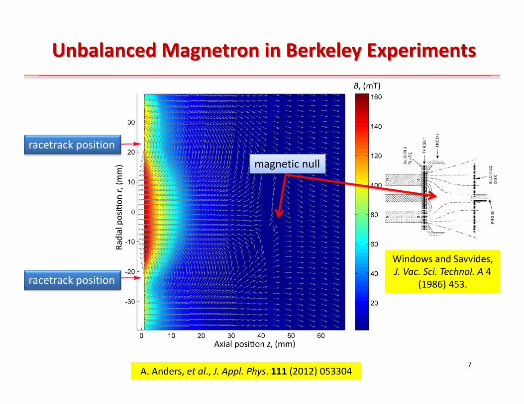
Unbalanced Magnetron in Berkeley Experiments
7
racetrack position
racetrack position
magnetic null
A. Anders, et al., J. Appl. Phys. 111 (2012) 053304
Windows and Savvides, J. Vac. Sci. Technol. A 4
(1986) 453.

Moving Ionization Zones
• 3” Nb target, peak current ~ 200 A• reduction of image exposure time
gives immediate clues on rotational speed ~ 104 m/s
8A. Anders et al., J. Appl. Phys. 111 (2012) 053304

9A. Anders et al., J. Appl. Phys. 111 (2012) 053304
Localization of Ionization and Self‐Organization

Ionization Zones: Evolution with Time and Current
• no ionization localization when current is just a few A
• at the 10 A level, bunching can be seen
• at the 100 A, well defined ionization zones exists
10A. Anders, Appl. Phys. Lett. 100 (2012) 224104.

Interesting Clues: Wake of Ionization Zones
intense, dense zones tend to have more extended wakes
11Nb in Kr 0.27 Pa @ 50 s, 137.7 A

Frame and Streak Camera Combination
12A. Anders et al., J. Appl. Phys. 111 (2012) 053304
end‐on viewframe image
end‐on viewstreak image

Magnetron as an Electron Trap

Pulse‐Averaged Electric Field in Plasma with Magnetic Field
Plasma potential in front of a racetrack of a magnetron (Nb sputtered in Ar), measure with emissive probe Average ion acceleration mostly toward to target
14
Plasma potentialwith respect to ground, (V)
Distance r from target center, (mm)
Distance z from target surface, (mm)
“racetrack”
“magneticPresheath”
J. Sanders, et al., Rev. Sci. Instrum. 82 (2011) 093505; A. Rauch et al., J. Appl. Phys. 111 (2012) 083302.
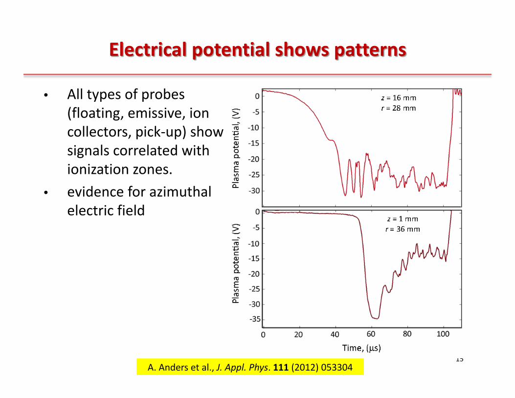
Electrical potential shows patterns
• All types of probes (floating, emissive, ion collectors, pick‐up) show signals correlated with ionization zones.
• evidence for azimuthal electric field
15A. Anders et al., J. Appl. Phys. 111 (2012) 053304
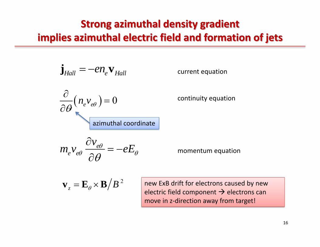
Strong azimuthal density gradient implies azimuthal electric field and formation of jets
16
0e en v
ee e
vm v eE
2z B v E B
Hall e Hallen j v current equation
continuity equation
momentum equation
new ExB drift for electrons caused by new electric field component electrons can move in z‐direction away from target!
azimuthal coordinate

17
Side‐on viewstreak
A. Anders et al., J. Appl. Phys. 111 (2012) 053304
most intense jet formation at the location of strongest azimuthal gradient
ee e
vm v eE

Side‐on viewframe
18A. Anders et al., J. Appl. Phys. 111 (2012) 053304

19
Simultaneousside‐on frame view
andside‐on streak view
A. Anders et al., J. Appl. Phys. 111 (2012) 053304
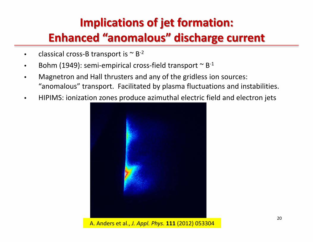
Implications of jet formation: Enhanced “anomalous” discharge current
• classical cross‐B transport is ~ B‐2
• Bohm (1949): semi‐empirical cross‐field transport ~ B‐1
• Magnetron and Hall thrusters and any of the gridless ion sources: “anomalous” transport. Facilitated by plasma fluctuations and instabilities.
• HIPIMS: ionization zones produce azimuthal electric field and electron jets
20A. Anders et al., J. Appl. Phys. 111 (2012) 053304

“Stopping power” of plasma for drifting electrons
many orders of magnitude!
21A. Anders et al., J. Appl. Phys. 111 (2012) 053304

Shape of Ionization
Zone
22A. Anders et al., J. Appl. Phys. 111 (2012) 053304

Motion and Self‐Organization of Ionization Zones
1. secondary electrons help amplifying the same zone that was the origin of the primary ion
2. sputtered atoms help amplifying the zone following the one of the primary ions
23
A. Anders, Appl. Phys. Lett. 100 (2012) 224104.

Velocity of the Ionization Zones
24
IZ IZ iv t IZ IZv d dt
,22 e e
IZ g em ureB
1 22 i
imps
mdtE Qe
1 22 sheath mps e
IZi
QV E mvB d m
thin slab or slice of plasma about to be removed from the plasma region, characteristic lengths is 2 rge
time of removal of ions is determined by inertia of ions accelerated in the local electric field
A. Anders, Appl. Phys. Lett. 100 (2012) 224104.

Velocity of the Ionization Zones
25
1 22 sheath mps e
IZi
QV E mvB d m
Let’s compare with experiments• B = 60 mT• Q = 1• Vsheath = 400 V• Emps = 5 x 10⁴ V/m• mi(Nb) = 93 x 1.66 x 10‐27 kg and mi(Ar) = 40 x 1.66 x 10‐27 kg• me = 9.1 x 10‐31 kg• d = 2 mm
gives and 0.2 0.3μsit 410 m/sIZv

Velocity of Ionization Zones: Experiments
26
target gas observed
azimuthal
velocities (m/s)
atomic mass
(amu)
surface binding
energy (eV)
atomic
mass
(amu)
Al 30.0 3.19 Ar 39.9 8100 ± 300
Al 30.0 3.19 Kr 83.8 5400 ± 300
Cu 63.5 3.48 Ar 39.9 4200 ± 400
Cu 63.5 3.48 Kr 83.8 4200 ± 150
Nb 92.9 5.93 Ar 39.9 7000 ± 2000
Nb 92.9 5.93 Kr 83.8 5700 ± 700
W 183.4 8.7 Ar 39.9 6250 ± 300
W 183.4 8.7 Kr 83.8 4000 ± 300A. Anders et al., J. Appl. Phys. 111 (2012) 053304

Mixed Metal / Gas Sputtering in HIPIMS
27A. Anders, et al., J. Phys D: Appl. Phys. 45 (2012) 012003.
“gas recycling”
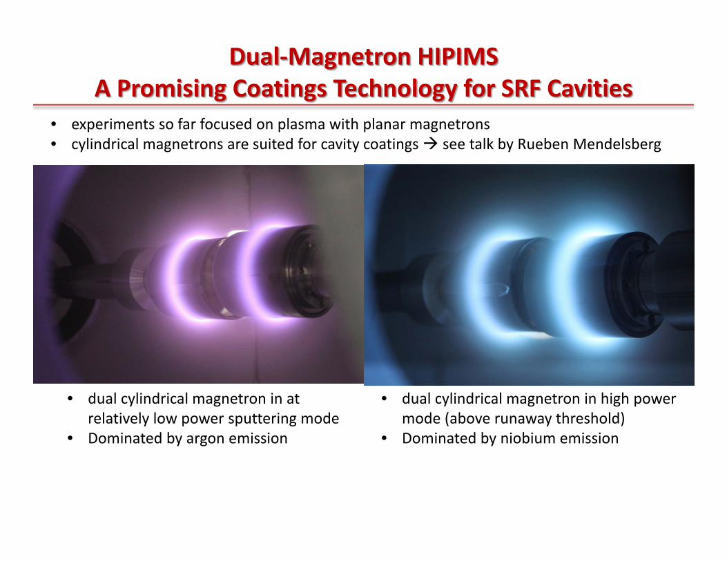
Dual‐Magnetron HIPIMSA Promising Coatings Technology for SRF Cavities
• dual cylindrical magnetron in at relatively low power sputtering mode
• Dominated by argon emission
• dual cylindrical magnetron in high power mode (above runaway threshold)
• Dominated by niobium emission
• experiments so far focused on plasma with planar magnetrons• cylindrical magnetrons are suited for cavity coatings see talk by Rueben Mendelsberg
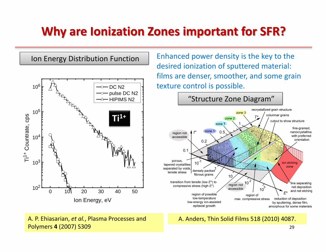
Why are Ionization Zones important for SFR?
29
“Structure Zone Diagram”
0 10 20 30 40 50102
103
104
105
106
Ti1+
Cou
ntra
te, c
ps
Ion Energy, eV
DC N2 pulse DC N2 HIPIMS N2
Ti1+
A. P. Ehiasarian, et al., Plasma Processes and Polymers 4 (2007) S309
Enhanced power density is the key to the desired ionization of sputtered material: films are denser, smoother, and some grain texture control is possible.
Ion Energy Distribution Function
A. Anders, Thin Solid Films 518 (2010) 4087.

Summary
1. Positive feedback loop between electron mean free path and ionization leads to “bunching” of plasma in ionization zones
2. Ionization zones move in ExB direction because ions are “evacuated” from ionization zones by electric field, exposing new neutrals to ionization by drifting electrons
3. electrons drift according to the local E and B fields, perpendicular to both, and produce electron jets related to the azimuthal electric field of the plasma zone
4. the physically relevant power density of HIPIMS is much higher than the typically quoted average power density
5. Ionization zones explain why HIPIMS works as observed, and offer “energetic condensation” in the context of sputtering and SRF coatings.
30