Embed Size (px)
Citation preview

Application ReportSLWA059–May 2010
LO Harmonic Effects on I/Q Balance and SidebandSuppression in Complex I/Q Modulators
Mike Arnold, Randy Class, Francesco Dantoni, Shrinivasan Jaganathan, and Roland Sperlich .......... HPA/HSP
ABSTRACT
This report describes the effect that high local oscillator (LO) harmonics have on the I/Q balance of acomplex (I/Q) modulator. The imbalance that is generated has a direct impact on sideband suppressionperformance of the I/Q modulator. This application report discusses the theoretical distortion generated bythe harmonics, along with measured results showing the effect on sideband suppression in a modulator. Italso presents the measured results showing the improvement in sideband suppression that can beobtained by filtering out the LO harmonics before they reach the modulator input.
Contents1 Introduction .................................................................................................................. 22 I/Q Modulator Operation ................................................................................................... 23 The Polyphase Bridge ...................................................................................................... 34 Effect of High LO Harmonics on the I/Q Quadrature Balance of a Polyphase Bridge ............................. 5
4.1 Case 1: Minimum Effective Phase Error Case ................................................................. 64.2 Case 2: Maximum Effective Phase Error Case ................................................................ 7
5 Relationship Between I/Q Error and Sideband Suppression .......................................................... 96 Measured Effect of LO Harmonics on Sideband Suppression ...................................................... 107 Improvement in Sideband Suppression by Employing an LO Filter ................................................ 138 Summary ................................................................................................................... 15
List of Figures
1 Basic I/Q Modulator Block Diagram ...................................................................................... 3
2 Polyphase Functional Blocks .............................................................................................. 3
3 Simple Polyphase Circuit and Transfer Equations ..................................................................... 3
4 Amplitude and Phase Characteristics of a Simple Polyphase Circuit................................................ 4
5 Polyphase-Limiter for Equalized Output Amplitude..................................................................... 5
6 Polyphase and Polyphase+Limiter Waveforms ......................................................................... 5
7 I Output, 0° Relative Input Phase: No Shift.............................................................................. 6
8 Q output, 0° Relative Input Phase: No Shift ............................................................................. 7
9 I Output, 90° Relative Input Phase: Large Shift to Left ................................................................ 8
10 Q Output, 90° Relative Input Phase: Small Shift to Right ............................................................. 8
11 I/Q Quadrature Error vs Third-Harmonic Amplitude and Initial Phase ............................................... 9
12 Resulting Image Band Levels for Presence of Third Harmonic ..................................................... 10
13 Test Set-up for Evaluating LO Harmonic Effects...................................................................... 11
14 TRF3703-33 Image Sideband Level in Presence of LO+Third Harmonic ......................................... 12
15 TRF3703-33 Worst-Case Image Sideband Level vs Harmonic Power ............................................ 13
16 Fifth-Order LPF Filter Schematic ........................................................................................ 13
17 Fifth-Order LPF Measured Response .................................................................................. 14
18 TRF3703-33 Worst-Case Image Sideband Level With LO Filtering ................................................ 15
1SLWA059–May 2010 LO Harmonic Effects on I/Q Balance and Sideband Suppression in Complex I/QModulators
Copyright © 2010, Texas Instruments Incorporated

Introduction www.ti.com
1 Introduction
Wireless basestation transmit chains increasingly use complex (I/Q) modulation techniques to directlymodulate baseband I/Q data onto an RF carrier. Direct modulation eliminates the need for an intermediateIF stage and associated filtering, which reduces transceiver board complexity, size, and cost. The keycomponent in this architecture is the complex (I/Q) modulator, and one of the critical performanceparameters is sideband suppression.
In-phase/quadrature (I/Q) modulation does not employ IF filtering – it is the job of the I/Q modulator toprovide the bulk of the rejection of the unwanted (or image) sideband. If an I/Q modulator is well balanced,it can provide enough sideband suppression so that no post-modulation filtering is required. This allows forzero-IF operation, where the desired sideband and image are a composite signal both centered at the LOfrequency. In cases where the baseband I/Q signal is translated up to an IF frequency, a filter can still beused at the modulator output to provide additional image rejection. The requirements on the filter aregreatly reduced because the modulator is already providing much of the needed rejection. From theperspective of input stimulus, the two keys to good sideband suppression for an I/Q modulator are:
1. Balanced I/Q baseband inputs [equal amplitude and quadrature (90°) phase]2. Quadrature phase balance of the LO signal fed to the mixers of the modulator.
No design is perfect, and a certain amount of imbalance in modulator internal LO and baseband paths isexpected. The combined effects of these imbalances can be corrected digitally by controlling the DACsused to generate the baseband I/Q signals. However, to ease system requirements on correctionalgorithms, it is always desirable to minimize these imbalances in the modulator design so that as littlecorrection as possible is needed. Even if the modulator design provides LO drive to the mixers in perfectquadrature, the balance can still be corrupted if the incoming LO signal contains high harmonic levels.
This application report explains the effects that high LO harmonic levels have on the balance of LO signalsfed to the mixers, and the associated effects that can be seen in sideband suppression.
2 I/Q Modulator Operation
A simple model of a complex I/Q modulator is shown in Figure 1. Under ideal balanced conditions, theoperation of the modulator with single CW tones applied is as follows:
• At the top mixer, a sin(wct) LO signal and Asin(wbbt) baseband I signal are mixed.• The output of the top mixer at RF1 consists of two terms:
– positive ½Acos((wc–wbb)t) [lower sideband]– negative ½Acos((wc+wbb)t) [upper sideband with 180° shift]
• The LO is shifted by 90° by some mechanism and fed to the bottom mixer.• At the bottom mixer, a cos(wct) LO signal and Acos(wbbt) baseband Q signal are mixed.• The output of the bottom mixer at RF2 consists of two terms:
– positive ½Acos((wc–wbb)t) [lower sideband]– positive ½Acos((wc+wbb)t) [upper sideband with 0° shift]
• The outputs of the two mixers are combined at a summing node.
– The two lower sideband terms add in-phase and produce the desired low-side outputAcos((wc–wbb)t).
– The two upper sideband terms are out-of-phase and cancel.• If I and Q inputs are swapped, or the polarity of either I or Q is reversed, the operation is the same,
except that the lower sideband terms cancel, and the upper sideband terms add, producing the desiredhigh-side output
2 LO Harmonic Effects on I/Q Balance and Sideband Suppression in Complex I/Q SLWA059–May 2010Modulators
Copyright © 2010, Texas Instruments Incorporated

LOInput
LO1
LO2
90°IF
RF1
RF2
IF
I Q
PolyphaseBridgeLO IN
I OUT (0°)
Q OUT (90°)
(a)
PolyphaseBridge
LO IN (0°)I OUT+ (0°)
Q OUT+ (90°)
(b)
LO IN (180°)
Q OUT- (270°)
I OUT- (180°)
Transfer Functions:
1LP( ) =
jωRC + 1
jωRCHP( )=
jωRC + 1
¦
f
LO _ in
LO _ I_ out
LO _ Q _ out
www.ti.com The Polyphase Bridge
Figure 1. Basic I/Q Modulator Block Diagram
As previously stated, for an ideal modulator the image output completely cancels if I/Q inputs are perfectlybalanced and the LO signals fed to the mixers are in perfect quadrature. Imperfections in the I/Qbaseband paths can be corrected for by controlling DAC output amplitude and phase. But how is the LOsplit, and quadrature maintained, especially when this function is integrated on-chip and must operate overa wide range of frequencies? In highly integrated I/Q modulator products such as the Texas InstrumentsTRF3703-xx and TRF3720, this operation is achieved by using a polyphase bridge.
3 The Polyphase Bridge
The polyphase function is shown in Figure 2. For a single-ended system, the LO input is divided intoin-phase (0°) and quadrature (90°) components. A differential polyphase circuit also can be implementedthat generates four LO components separated by 90°. The 0°/180° pair forms the in-phase differentialoutput, and the 90°/270° pair forms the quadrature differential output.
Figure 2. Polyphase Functional Blocks
The circuit of a first-order, single-ended, polyphase bridge is shown in Figure 3. The bridge consists ofcomplementary RC sections that create a low-pass transfer function from input to one output and ahigh-pass transfer function from input to the other output.
Figure 3. Simple Polyphase Circuit and Transfer Equations
3SLWA059–May 2010 LO Harmonic Effects on I/Q Balance and Sideband Suppression in Complex I/QModulators
Copyright © 2010, Texas Instruments Incorporated

0.1 1 1020
15
10
5
0– 0.043
– 20
20 • log HP f( )( )
20 • log LP f( )( )
100.1 f
0.1 1 10100
50
0
50
100100
100
Phase_HP f( )
Phase_LP f( )
Delta_phase f( )
100.1 f
The Polyphase Bridge www.ti.com
If the R and C values of the two polyphase legs are matched, the amplitude and phase characteristics ofthe outputs are as depicted in Figure 4. Both legs have the same corner frequency, but more importantly,the phase of one leg tracks the other leg with a 90° shift. The differential phase between legs is the browndashed line in the phase plot of Figure 4, and the 90° shift can be maintained over a wide frequencyrange.
The circuit also can be operated above and below the f = 1 crossover frequency in Figure 4 by includinglimiters at the output of the polyphase circuit as shown in Figure 5. With limiters included at the polyphaseoutput, the sinusoidal outputs of the polyphase are converted to square waves with leading/trailing edgesat the zero-crossing locations as shown in Figure 6. If the polyphase is balanced and the input LO is freeof harmonic content, the I and Q square waves are in quadrature, and the amplitudes are equal. Thesesignals are the ideal switching waveforms needed to drive the modulator mixers.
Higher-order polyphase circuits usually are employed which provide better amplitude balance over aneven wider frequency range. For the purposes of this discussion, the focus is on the simple first-ordercircuit.
Figure 4. Amplitude and Phase Characteristics of a Simple Polyphase Circuit
4 LO Harmonic Effects on I/Q Balance and Sideband Suppression in Complex I/Q SLWA059–May 2010Modulators
Copyright © 2010, Texas Instruments Incorporated

PolyphaseBridgeLO IN
LO OUT I (0°)
LO OUT Q (90°)
Limiter
Limiter
POLYPHASE I/Q Outputs -90° Phase Shift but Unequal Amplitude
LIMITER I/Q Outputs - 90° Phase Shift and Equal Amplitude
90°
( )LO_in = sin 2 tfp
( )LOp ¦ fILO_in = a sin 2 t +
( )Q LOLO_Q = a sin 2 t +
2pp¦ f -
( ) ( )n nLO_in = sin 2 t + b sin 2 n t +p¦ p ¦ f
( ) ( )p¦ f p¦ f fI LO I n ILO_I = a sin 2 t + + b sin 2 t + +
( ) ( )pp¦ f - p ¦ f fQ LO Q n QLO_Q = a sin 2 t + + b sin 2 n t + +2
www.ti.com Effect of High LO Harmonics on the I/Q Quadrature Balance of a Polyphase Bridge
Figure 5. Polyphase-Limiter for Equalized Output Amplitude
Figure 6. Polyphase and Polyphase+Limiter Waveforms
4 Effect of High LO Harmonics on the I/Q Quadrature Balance of a Polyphase Bridge
The general input and output equations of the polyphase bridge with no harmonics present are as follows:
(1)
(2)
(3)
Depending on the operating frequency, the I and Q output signals may or may not have equal amplitude.Again, this imbalance is removed by the limiters after the polyphase bridge. fLO represents an offsetinsertion phase common to both the I and Q paths. The important point is that the Q output is shifted byp/2, or 90°, relative to the I output.
Now consider the case where a single nth-harmonic of the LO frequency is present at the polyphase inputwith an arbitrary phase relative to the LO. In this case, the equations are as follows:
(4)
(5)
(6)
The bn and fn terms are the amplitude and phase of the input nth-harmonic relative to the fundamental LO.The bI and bQ terms are the amplitude of the harmonic that reach the I and Q output, and depend on theloss through each polyphase leg at the nth-harmonic frequency. fI and fQ are the phase shift through eachpolyphase leg at the nth-harmonic frequency.
5SLWA059–May 2010 LO Harmonic Effects on I/Q Balance and Sideband Suppression in Complex I/QModulators
Copyright © 2010, Texas Instruments Incorporated

( )n_minLO_in = sin(2 t) + 0.1 sin 6 t +p¦ p¦ f
( )LO_I = 0.707 sin(2 t) + 0.09 sin 6 t + 0¦ ¦p p
( ) ( )LO_Q = 0.707 sin 2 t + 0.032 sin 6 t2 2
¦ - ¦ -p pp p
I Output
0 0.25 0.5 0.75 1 1.25 1.5 1.75 2
Time
LO alone
3LO alone
LO+3LO
-0.8
-0.6
-0.4
-0.2
0
0.2
0.4
0.6
0.8
Am
plitu
de
Effect of High LO Harmonics on the I/Q Quadrature Balance of a Polyphase Bridge www.ti.com
Based on these equations, the I and Q outputs of the polyphase are sinusoidal waveforms superimposedwith an nth-harmonic sinusoid with some arbitrary amplitude and phase. As can be seen in the followingfigures, the composite waveforms are distorted, and most importantly, the zero-crossings are shiftedcausing a quadrature error between I and Q waveforms. The amount of quadrature error depends on therelative phase between the fundamental LO and the nth-harmonic. This can be illustrated with two cases.
4.1 Case 1: Minimum Effective Phase Error Case
Consider a simplified case where the LO frequency is at the crossover point f = 1 in Figure 4, withamplitude of 1 V. Also for simplification, set fLO = 0 so that all phases are referenced to 0. The power issplit between I and Q outputs, so aI = aQ = 0.707 V. Also assume that a third harmonic is present at theinput with relative amplitude of bn = 0.1 V and relative phase shift fn_min such that fn+fI = 0 (fn+fQ = –90).From Figure 4, the I path passes the third harmonic (f=3) with ~0.5-dB attenuation, so bI ~ 0.1×0.9 ~ 0.09.The Q path passes the third harmonic with ~10-dB attenuation, so bQ ~ 0.1 × 0.32 ~ 0.032. For this case,the equations reduce to:
(7)
(8)
(9)
Figure 7 shows the I output waveforms. The zero-crossing locations of the composite I output (LO+3LO)have not been affected because the fundamental- and third-harmonic zero-crossing points are coincident.The amplitude of the output has been distorted but the limiters remove this after the polyphase bridge.
Figure 8 shows the Q output waveforms. The results are similar to the I output in that the zero-crossingsare coincident, so amplitude is distorted but no change in zero-crossing locations of the composite outputoccurs.
The overall effect for this case is no phase shift in either the I or Q output.
Figure 7. I Output, 0° Relative Input Phase: No Shift
6 LO Harmonic Effects on I/Q Balance and Sideband Suppression in Complex I/Q SLWA059–May 2010Modulators
Copyright © 2010, Texas Instruments Incorporated

Q Output
-1
-0.8
-0.6
-0.4
-0.2
0
0.2
0.4
0.6
0.8
1
0 0.25 0.5 0.75 1 1.25 1.5 1.75 2
Time
LO alone
3LO alone
LO+3LO
Am
plitu
de
( )nLO_in = sin(2 t) + 0.1 sin 6 t +p¦ p¦ f
( ) ( )LO_I = 0.707 sin 2 t + 0.09 sin 6 t +2
¦ ¦ pp p
( ) ( )LO_Q = 0.707 sin 2 t + 0.032 sin 6 t + 02
¦ - ¦pp p
www.ti.com Effect of High LO Harmonics on the I/Q Quadrature Balance of a Polyphase Bridge
Figure 8. Q output, 0° Relative Input Phase: No Shift
4.2 Case 2: Maximum Effective Phase Error Case
Now consider the case where all conditions are the same as in Case 1 except that the relative phase shiftof the third harmonic fn_max is such that fn+fI = 90 (fn+fQ = 0). For this case, the equations reduce to:
(10)
(11)
(12)
Both the I and Q outputs have harmonic components that are out-of-phase with the fundamental tone.This causes a maximum shift in the zero-crossing locations of the composite signal. Figure 9 shows thatthe I output zero-crossings have been shifted to the left; Figure 10 shows that the Q output zero-crossingshave been shifted to the right. Less shift in the Q output occurs because the harmonic voltage is less, butthe overall effect is that the relative phase between I and Q zero-crossings has been shifted away fromperfect quadrature (90°).
7SLWA059–May 2010 LO Harmonic Effects on I/Q Balance and Sideband Suppression in Complex I/QModulators
Copyright © 2010, Texas Instruments Incorporated

I Output
PHASE SHIFT
0 0.25 0.5 0.75 1 1.25 1.5 1.75 2
Time
-1
-0.8
-0.6
-0.4
-0.2
0
0.2
0.4
0.6
0.8
1
Am
plitu
de
LO alone
3LO alone
LO+3LO
Q Output
-0.8
-0.6
-0.4
-0.2
0
0.2
0.4
0.6
0.8
Am
plitu
de
0 0.25 0.5 0.75 1 1.25 1.5 1.75 2
Time
LO alone
3LO alone
LO+3LO
Effect of High LO Harmonics on the I/Q Quadrature Balance of a Polyphase Bridge www.ti.com
Figure 9. I Output, 90° Relative Input Phase: Large Shift to Left
Figure 10. Q Output, 90° Relative Input Phase: Small Shift to Right
The preceding two cases are the extremes for a third-harmonic presence. But what happens in general foran arbitrary relative phase between LO and third harmonic?
8 LO Harmonic Effects on I/Q Balance and Sideband Suppression in Complex I/Q SLWA059–May 2010Modulators
Copyright © 2010, Texas Instruments Incorporated
I/O Quadrature Error - deg
3rd Harmonic Initial Phase - deg
0 180 360 540 720 1080
13
12
11
10
9
8
7
6
5
4
3
2
1
cos
2
2
G 2Gcos + 1Suppression (dBc) = 20log
G + 2G + 1
- f
f
www.ti.com Relationship Between I/Q Error and Sideband Suppression
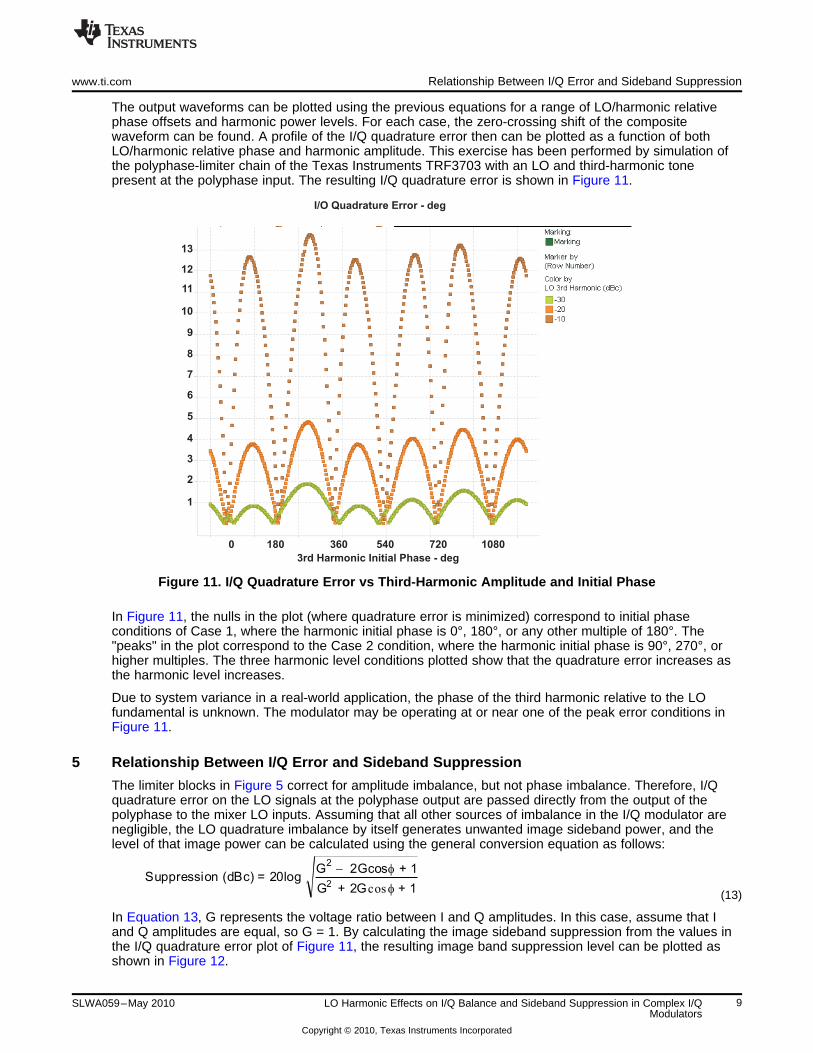
The output waveforms can be plotted using the previous equations for a range of LO/harmonic relativephase offsets and harmonic power levels. For each case, the zero-crossing shift of the compositewaveform can be found. A profile of the I/Q quadrature error then can be plotted as a function of bothLO/harmonic relative phase and harmonic amplitude. This exercise has been performed by simulation ofthe polyphase-limiter chain of the Texas Instruments TRF3703 with an LO and third-harmonic tonepresent at the polyphase input. The resulting I/Q quadrature error is shown in Figure 11.
Figure 11. I/Q Quadrature Error vs Third-Harmonic Amplitude and Initial Phase
In Figure 11, the nulls in the plot (where quadrature error is minimized) correspond to initial phaseconditions of Case 1, where the harmonic initial phase is 0°, 180°, or any other multiple of 180°. The"peaks" in the plot correspond to the Case 2 condition, where the harmonic initial phase is 90°, 270°, orhigher multiples. The three harmonic level conditions plotted show that the quadrature error increases asthe harmonic level increases.
Due to system variance in a real-world application, the phase of the third harmonic relative to the LOfundamental is unknown. The modulator may be operating at or near one of the peak error conditions inFigure 11.
5 Relationship Between I/Q Error and Sideband Suppression
The limiter blocks in Figure 5 correct for amplitude imbalance, but not phase imbalance. Therefore, I/Qquadrature error on the LO signals at the polyphase output are passed directly from the output of thepolyphase to the mixer LO inputs. Assuming that all other sources of imbalance in the I/Q modulator arenegligible, the LO quadrature imbalance by itself generates unwanted image sideband power, and thelevel of that image power can be calculated using the general conversion equation as follows:
(13)
In Equation 13, G represents the voltage ratio between I and Q amplitudes. In this case, assume that Iand Q amplitudes are equal, so G = 1. By calculating the image sideband suppression from the values inthe I/Q quadrature error plot of Figure 11, the resulting image band suppression level can be plotted asshown in Figure 12.
9SLWA059–May 2010 LO Harmonic Effects on I/Q Balance and Sideband Suppression in Complex I/QModulators
Copyright © 2010, Texas Instruments Incorporated
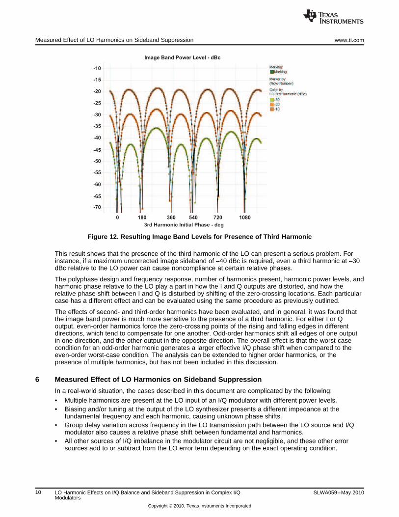
Image Band Power Level - dBc
3rd Harmonic Initial Phase - deg
0 180 360 540 720 1080
-10
-15
-20
-25
-30
-35
-40
-45
-50
-55
-60
-65
-70
Measured Effect of LO Harmonics on Sideband Suppression www.ti.com
Figure 12. Resulting Image Band Levels for Presence of Third Harmonic
This result shows that the presence of the third harmonic of the LO can present a serious problem. Forinstance, if a maximum uncorrected image sideband of –40 dBc is required, even a third harmonic at –30dBc relative to the LO power can cause noncompliance at certain relative phases.
The polyphase design and frequency response, number of harmonics present, harmonic power levels, andharmonic phase relative to the LO play a part in how the I and Q outputs are distorted, and how therelative phase shift between I and Q is disturbed by shifting of the zero-crossing locations. Each particularcase has a different effect and can be evaluated using the same procedure as previously outlined.
The effects of second- and third-order harmonics have been evaluated, and in general, it was found thatthe image band power is much more sensitive to the presence of a third harmonic. For either I or Qoutput, even-order harmonics force the zero-crossing points of the rising and falling edges in differentdirections, which tend to compensate for one another. Odd-order harmonics shift all edges of one outputin one direction, and the other output in the opposite direction. The overall effect is that the worst-casecondition for an odd-order harmonic generates a larger effective I/Q phase shift when compared to theeven-order worst-case condition. The analysis can be extended to higher order harmonics, or thepresence of multiple harmonics, but has not been included in this discussion.
6 Measured Effect of LO Harmonics on Sideband Suppression
In a real-world situation, the cases described in this document are complicated by the following:
• Multiple harmonics are present at the LO input of an I/Q modulator with different power levels.• Biasing and/or tuning at the output of the LO synthesizer presents a different impedance at the
fundamental frequency and each harmonic, causing unknown phase shifts.• Group delay variation across frequency in the LO transmission path between the LO source and I/Q
modulator also causes a relative phase shift between fundamental and harmonics.• All other sources of I/Q imbalance in the modulator circuit are not negligible, and these other error
sources add to or subtract from the LO error term depending on the exact operating condition.
10 LO Harmonic Effects on I/Q Balance and Sideband Suppression in Complex I/Q SLWA059–May 2010Modulators
Copyright © 2010, Texas Instruments Incorporated
R&S
SMUH
HP
8673H
Spec-A
LO_N
ESG
I
Q
RF
PSA
TRF3703
COMBINE
Flo MHz
n*Flo MHz
Flo MHz @0 dBm/varied phase
n*Flo MHz @varied power
10 MHz REF
www.ti.com Measured Effect of LO Harmonics on Sideband Suppression
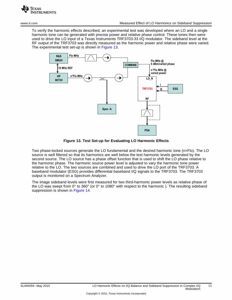
To verify the harmonic effects described, an experimental test was developed where an LO and a singleharmonic tone can be generated with precise power and relative phase control. These tones then wereused to drive the LO input of a Texas Instruments TRF3703-33 I/Q modulator. The sideband level at theRF output of the TRF3703 was directly measured as the harmonic power and relative phase were varied.The experimental test set-up is shown in Figure 13.
Figure 13. Test Set-up for Evaluating LO Harmonic Effects
Two phase-locked sources generate the LO fundamental and the desired harmonic tone (n×Flo). The LOsource is well filtered so that its harmonics are well below the test harmonic levels generated by thesecond source. The LO source has a phase offset function that is used to shift the LO phase relative tothe harmonic phase. The harmonic source power level is adjusted to vary the harmonic tone powerrelative to the LO. The two sources are combined and used to drive the LO port of the TRF3703. Abaseband modulator (ESG) provides differential baseband I/Q signals to the TRF3703. The TRF3703output is monitored on a Spectrum Analyzer.
The image sideband levels were first measured for two third-harmonic power levels as relative phase ofthe LO was swept from 0° to 360° (or 0° to 1080° with respect to the harmonic ). The resulting sidebandsuppression is shown in Figure 14.
11SLWA059–May 2010 LO Harmonic Effects on I/Q Balance and Sideband Suppression in Complex I/QModulators
Copyright © 2010, Texas Instruments Incorporated

3703 Measured SSB
LO PHASE3
rdHarm PHASE 0 180 360 540 720 900 1080
3rd Harm Power = -20 dBm
3rd Harm Power = -30 dBm
Measured Effect of LO Harmonics on Sideband Suppression www.ti.com
Figure 14. TRF3703-33 Image Sideband Level in Presence of LO+Third Harmonic
The sideband suppression follows the same pattern as the simulated case in Figure 12, with the peaksand nulls in sideband suppression spaced 180° apart with respect to the harmonic phase. The patternsshown in Figure 14 are shifted on the x-axis because the absolute starting phase relationship between theLO and harmonic was not experimentally determined for each harmonic power case. The sidebandsuppression also degrades as harmonic power is increased, as predicted by the plot in Figure 12.
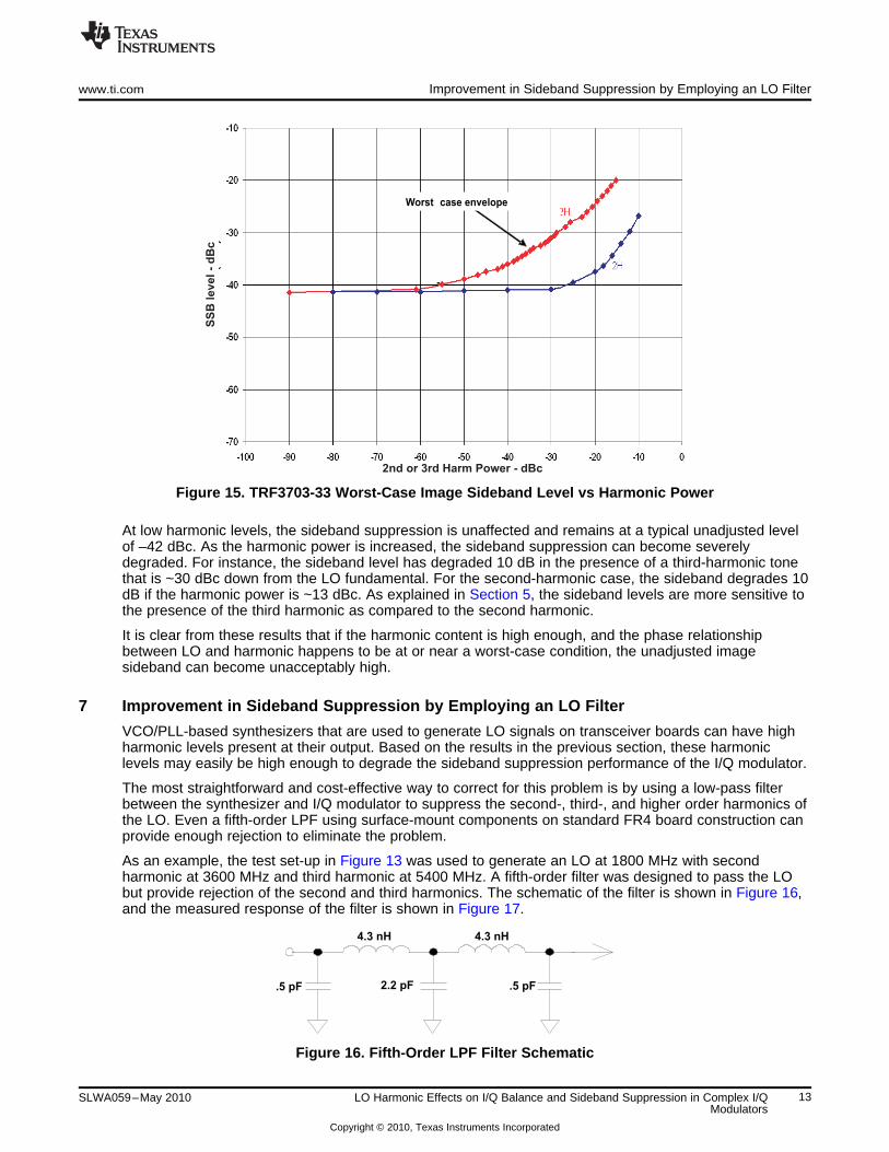
A second test was conducted to determine the sideband level generated over a wide range of harmonicpower levels for the worst-case LO/harmonic phase condition. For this test, the harmonic power wasadjusted to a desired level and the phase adjustment was varied to maximize the sideband level. This wasrepeated for several power levels from –90 dBc to –10 dBc. The test was performed for bothLO+2nd-harmonic and LO+3rd-harmonic conditions. The results are shown in Figure 15.
12 LO Harmonic Effects on I/Q Balance and Sideband Suppression in Complex I/Q SLWA059–May 2010Modulators
Copyright © 2010, Texas Instruments Incorporated
Worst
-
case envelopeS
SB
level -
dB
c
2nd or 3rd Harm Power - dBc
.5 pF .5 pF2.2 pF
4.3 nH 4.3 nH
www.ti.com Improvement in Sideband Suppression by Employing an LO Filter
Figure 15. TRF3703-33 Worst-Case Image Sideband Level vs Harmonic Power
At low harmonic levels, the sideband suppression is unaffected and remains at a typical unadjusted levelof –42 dBc. As the harmonic power is increased, the sideband suppression can become severelydegraded. For instance, the sideband level has degraded 10 dB in the presence of a third-harmonic tonethat is ~30 dBc down from the LO fundamental. For the second-harmonic case, the sideband degrades 10dB if the harmonic power is ~13 dBc. As explained in Section 5, the sideband levels are more sensitive tothe presence of the third harmonic as compared to the second harmonic.
It is clear from these results that if the harmonic content is high enough, and the phase relationshipbetween LO and harmonic happens to be at or near a worst-case condition, the unadjusted imagesideband can become unacceptably high.
7 Improvement in Sideband Suppression by Employing an LO Filter
VCO/PLL-based synthesizers that are used to generate LO signals on transceiver boards can have highharmonic levels present at their output. Based on the results in the previous section, these harmoniclevels may easily be high enough to degrade the sideband suppression performance of the I/Q modulator.
The most straightforward and cost-effective way to correct for this problem is by using a low-pass filterbetween the synthesizer and I/Q modulator to suppress the second-, third-, and higher order harmonics ofthe LO. Even a fifth-order LPF using surface-mount components on standard FR4 board construction canprovide enough rejection to eliminate the problem.
As an example, the test set-up in Figure 13 was used to generate an LO at 1800 MHz with secondharmonic at 3600 MHz and third harmonic at 5400 MHz. A fifth-order filter was designed to pass the LObut provide rejection of the second and third harmonics. The schematic of the filter is shown in Figure 16,and the measured response of the filter is shown in Figure 17.
Figure 16. Fifth-Order LPF Filter Schematic
13SLWA059–May 2010 LO Harmonic Effects on I/Q Balance and Sideband Suppression in Complex I/QModulators
Copyright © 2010, Texas Instruments Incorporated
Improvement in Sideband Suppression by Employing an LO Filter www.ti.com
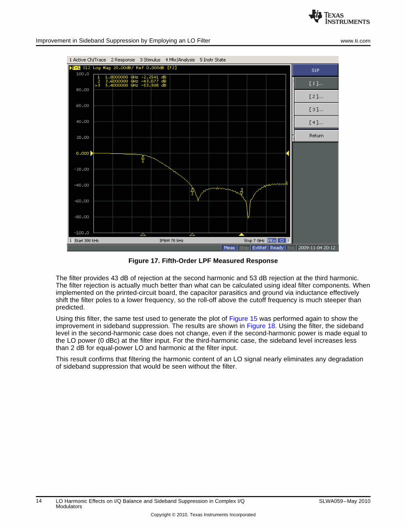
Figure 17. Fifth-Order LPF Measured Response
The filter provides 43 dB of rejection at the second harmonic and 53 dB rejection at the third harmonic.The filter rejection is actually much better than what can be calculated using ideal filter components. Whenimplemented on the printed-circuit board, the capacitor parasitics and ground via inductance effectivelyshift the filter poles to a lower frequency, so the roll-off above the cutoff frequency is much steeper thanpredicted.
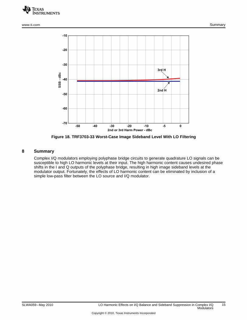
Using this filter, the same test used to generate the plot of Figure 15 was performed again to show theimprovement in sideband suppression. The results are shown in Figure 18. Using the filter, the sidebandlevel in the second-harmonic case does not change, even if the second-harmonic power is made equal tothe LO power (0 dBc) at the filter input. For the third-harmonic case, the sideband level increases lessthan 2 dB for equal-power LO and harmonic at the filter input.
This result confirms that filtering the harmonic content of an LO signal nearly eliminates any degradationof sideband suppression that would be seen without the filter.
14 LO Harmonic Effects on I/Q Balance and Sideband Suppression in Complex I/Q SLWA059–May 2010Modulators
Copyright © 2010, Texas Instruments Incorporated
-70
-60
-50
-40
-30
-20
-10
-50 -40 -30 -20 -10 -5 0
2nd or 3rd Harm Power - dBc
3rd H
2nd H
SS
B -
dB
c
www.ti.com Summary
Figure 18. TRF3703-33 Worst-Case Image Sideband Level With LO Filtering
8 Summary
Complex I/Q modulators employing polyphase bridge circuits to generate quadrature LO signals can besusceptible to high LO harmonic levels at their input. The high harmonic content causes undesired phaseshifts in the I and Q outputs of the polyphase bridge, resulting in high image sideband levels at themodulator output. Fortunately, the effects of LO harmonic content can be eliminated by inclusion of asimple low-pass filter between the LO source and I/Q modulator.
15SLWA059–May 2010 LO Harmonic Effects on I/Q Balance and Sideband Suppression in Complex I/QModulators
Copyright © 2010, Texas Instruments Incorporated
IMPORTANT NOTICE
Texas Instruments Incorporated and its subsidiaries (TI) reserve the right to make corrections, modifications, enhancements, improvements,and other changes to its products and services at any time and to discontinue any product or service without notice. Customers shouldobtain the latest relevant information before placing orders and should verify that such information is current and complete. All products aresold subject to TI’s terms and conditions of sale supplied at the time of order acknowledgment.
TI warrants performance of its hardware products to the specifications applicable at the time of sale in accordance with TI’s standardwarranty. Testing and other quality control techniques are used to the extent TI deems necessary to support this warranty. Except wheremandated by government requirements, testing of all parameters of each product is not necessarily performed.
TI assumes no liability for applications assistance or customer product design. Customers are responsible for their products andapplications using TI components. To minimize the risks associated with customer products and applications, customers should provideadequate design and operating safeguards.
TI does not warrant or represent that any license, either express or implied, is granted under any TI patent right, copyright, mask work right,or other TI intellectual property right relating to any combination, machine, or process in which TI products or services are used. Informationpublished by TI regarding third-party products or services does not constitute a license from TI to use such products or services or awarranty or endorsement thereof. Use of such information may require a license from a third party under the patents or other intellectualproperty of the third party, or a license from TI under the patents or other intellectual property of TI.
Reproduction of TI information in TI data books or data sheets is permissible only if reproduction is without alteration and is accompaniedby all associated warranties, conditions, limitations, and notices. Reproduction of this information with alteration is an unfair and deceptivebusiness practice. TI is not responsible or liable for such altered documentation. Information of third parties may be subject to additionalrestrictions.
Resale of TI products or services with statements different from or beyond the parameters stated by TI for that product or service voids allexpress and any implied warranties for the associated TI product or service and is an unfair and deceptive business practice. TI is notresponsible or liable for any such statements.
TI products are not authorized for use in safety-critical applications (such as life support) where a failure of the TI product would reasonablybe expected to cause severe personal injury or death, unless officers of the parties have executed an agreement specifically governingsuch use. Buyers represent that they have all necessary expertise in the safety and regulatory ramifications of their applications, andacknowledge and agree that they are solely responsible for all legal, regulatory and safety-related requirements concerning their productsand any use of TI products in such safety-critical applications, notwithstanding any applications-related information or support that may beprovided by TI. Further, Buyers must fully indemnify TI and its representatives against any damages arising out of the use of TI products insuch safety-critical applications.
TI products are neither designed nor intended for use in military/aerospace applications or environments unless the TI products arespecifically designated by TI as military-grade or "enhanced plastic." Only products designated by TI as military-grade meet militaryspecifications. Buyers acknowledge and agree that any such use of TI products which TI has not designated as military-grade is solely atthe Buyer's risk, and that they are solely responsible for compliance with all legal and regulatory requirements in connection with such use.
TI products are neither designed nor intended for use in automotive applications or environments unless the specific TI products aredesignated by TI as compliant with ISO/TS 16949 requirements. Buyers acknowledge and agree that, if they use any non-designatedproducts in automotive applications, TI will not be responsible for any failure to meet such requirements.
Following are URLs where you can obtain information on other Texas Instruments products and application solutions:
Products Applications
Amplifiers amplifier.ti.com Audio www.ti.com/audio
Data Converters dataconverter.ti.com Automotive www.ti.com/automotive
DLP® Products www.dlp.com Communications and www.ti.com/communicationsTelecom
DSP dsp.ti.com Computers and www.ti.com/computersPeripherals
Clocks and Timers www.ti.com/clocks Consumer Electronics www.ti.com/consumer-apps
Interface interface.ti.com Energy www.ti.com/energy
Logic logic.ti.com Industrial www.ti.com/industrial
Power Mgmt power.ti.com Medical www.ti.com/medical
Microcontrollers microcontroller.ti.com Security www.ti.com/security
RFID www.ti-rfid.com Space, Avionics & www.ti.com/space-avionics-defenseDefense
RF/IF and ZigBee® Solutions www.ti.com/lprf Video and Imaging www.ti.com/video
Wireless www.ti.com/wireless-apps
Mailing Address: Texas Instruments, Post Office Box 655303, Dallas, Texas 75265Copyright © 2010, Texas Instruments Incorporated