Embed Size (px)
Citation preview
LMI ELECTRONIC DOSING PUMPS
Code : P1
Basic manual
Instruction supplement
Spare parts list for drive assembly
Declaration « CE » of conformity
List of « Technical assistance » and « spare parts » departments
07/98

INSTRUCTION MANUAL
FOR INSTALLATION, OPERATING, AND MAINTENANCE.
LMI ELECTRONIC DOSING PUMPS Diaphragm liquid end
Basic manual
This manual should be made available to the person responsible for installation, operating and maintenance.
Date : 02/2012 Ref : 160.0101.001 Rev. D Replaces Rev. 0 09/98

LMI, Doseur à membrane, L001, Rev.B, 1098
CONTENTS
I – DESCRIPTION
I – 1. UnpackingI – 2. DescriptionI – 3. AccessoriesI – 4. Precautions
II – INSTALLATION
II – 1. Hydraulic installationII – 2. Electrical installation
III – START UP
III – 1. PrimingIII – 2. Output adjustment controlsIII – 3. CalibrationIII – 4. Volumetric calibration in external modeIII – 5. Pressure control
IV – MAINTENANCE
IV – 1. Spare parts replacementsIV – 2. Checking pump for proper zeroing (stroke knob)IV – 3. TroubleshootingIV – 4. EPU Resistance chart

0.0 Precautions
The pump described here may be used for the dosing of liquid products in connection with the applications set out in this manual. The following precautions should be taken when working with LMI metering pumps. Please read this section carefully prior to installation.
Storage precautions - Storage period of less than six months: The product should preferably be stored in its original packing and be protected from bad weather. - Storage period of more than six months: Store the pump in its original packing. It should be stored covered by a heat-sealing plastic cover and desiccant bags should be used (quantity dependent on volume and planned storage period). Store away from the influence of bad weather.
Protective Clothing ALWAYS wear protective clothing, face shield, safety glasses and gloves when working on or near your metering pump. Additional precautions should be taken depending on the solution being pumped. Refer to MSDS precautions from your solution supplier.
Water Pre-Prime All LMI pumps are pre-primed with water when shipped from the factory. If your solution is not compatible with water, disassemble the Pump Head Assembly. Thoroughly dry the pump head, valves, seal rings, balls and Liquifram™
(diaphragm). Reassemble head assembly tightening screws in a crisscross pattern. Refill the pump head with the solution to be pumped before priming the pump. (This will aid in priming.)
Solution Compatibility Determine if the materials of construction included in the liquid handling portion of your pump are adequate for the solution (chemical) to be pumped. Always refer to the solution supplier and the LMI Chemical Resistance Chart for compatibility of your specific LMI metering pump. Contact your local MRE distributor for further information.
Tubing Connections Inlet and outlet tubing or pipe sizes must not be reduced. Outlet tubing size must not be increased. Make certain that any tubing is SECURELY ATTACHED to fittings prior to start-up (see Section ., Tubing Connections). ALWAYS use LMI supplied tubing with your pump, as the tubing is specifically designed for use with the pump fittings. It is recommended that all tubing be shielded and secure to prevent possible injury in case of rupture or accidental damage. If tubing is exposed to sunlight, black UV resistant tubing should be installed. Check tubing frequently for cracks and replace as necessary.
Vinyl Tubing Your carton may contain a roll of clear vinyl tubing; this is only for connection to the return line of the FastPrime™ Head and must not be used as discharge tubing.
Connectors All connectors shall be tightened by hand. An additional turn of 1/8 to 1/4 might be necessary to ensure tightness. Any excessive tightening or using a toolmight damage the connecting device and the seals or the liquid end. All LMI pumps have straight screw machine threads on the head and fittings and are sealed by the O-rings. DO NOT use Teflon® tape or pipe dope to seal threads. Teflon® Tape may only be used on the 1/2" NPT thread side of the Injection Check Valve, the stainless steel liquid end connections, or if piping is directly connected to the pipe threads of the suction or discharge fittings.
Installation Always comply with local regulations and requirements. Always adhere to your local plumbing codes and requirements. Be sure installation does not constitute a cross connection. Check local plumbing codes for guidelines. Milton Roy Europe is not responsible for improper installations.
Back Pressure/Anti-syphon valve If you are pumping downhill or into low or no pressure system, a back pressure/antisyphon device such as LMI’s Four-Function Valve should be installed to prevent over pumping or siphoning. Contact your distributor for further information..
Electrical Connections WARNING: To reduce the risk of electrical shock, the metering pump must be plugged into a properly grounded grounding-type receptacle with ratings conforming to the data on the pump nameplate.. Do not use adapters! All wiring must conform to local electrical codes. If the supply cord is damaged, it must be replaced by the manufacturer, stocking distributor, or authorized repair centre in order to avoid a hazard..
Environment The ambient temperature must be less than 50°C. Avoid direct exposure to sunlight. The pump must be accessible and situated in a ventilated room.
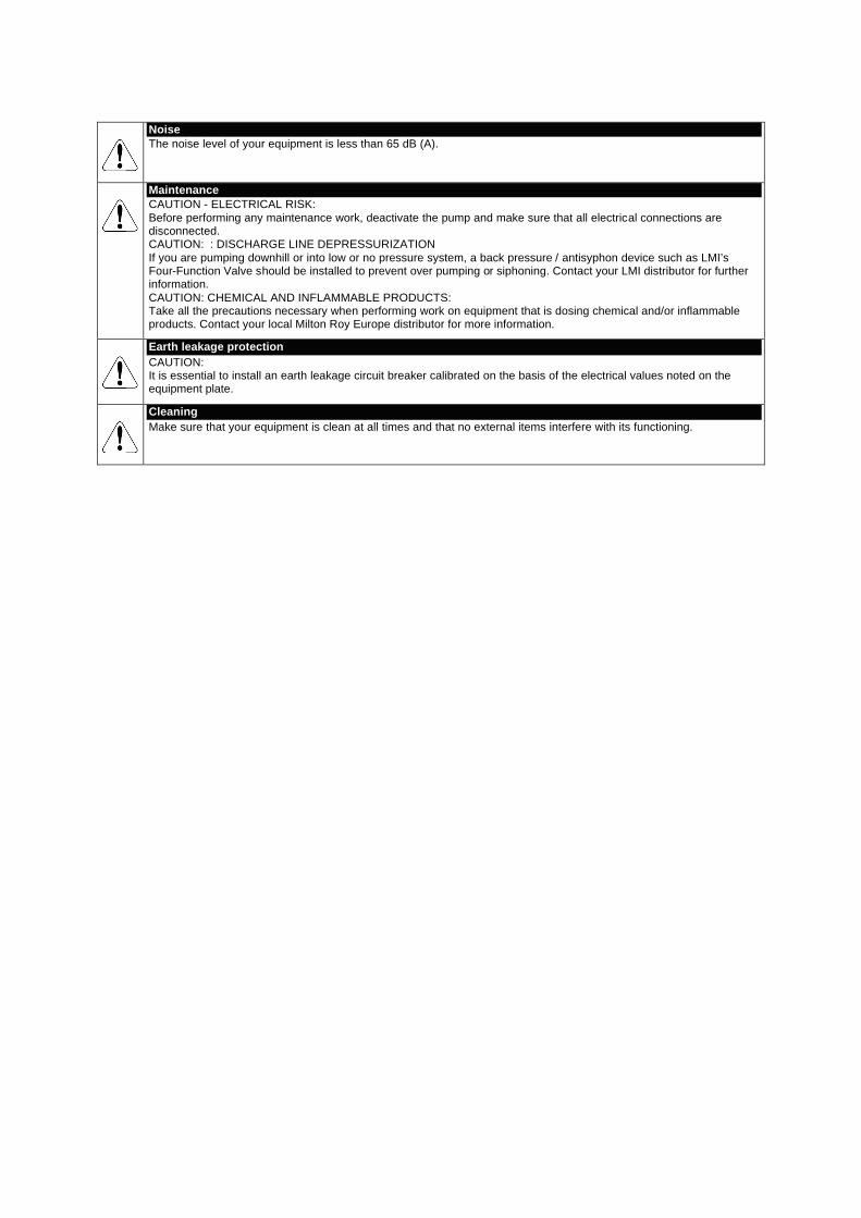
Noise The noise level of your equipment is less than 65 dB (A).
Maintenance CAUTION - ELECTRICAL RISK: Before performing any maintenance work, deactivate the pump and make sure that all electrical connections are disconnected. CAUTION: : DISCHARGE LINE DEPRESSURIZATION If you are pumping downhill or into low or no pressure system, a back pressure / antisyphon device such as LMI’s Four-Function Valve should be installed to prevent over pumping or siphoning. Contact your LMI distributor for further information. CAUTION: CHEMICAL AND INFLAMMABLE PRODUCTS: Take all the precautions necessary when performing work on equipment that is dosing chemical and/or inflammable products. Contact your local Milton Roy Europe distributor for more information.
Earth leakage protection CAUTION: It is essential to install an earth leakage circuit breaker calibrated on the basis of the electrical values noted on the equipment plate.
Cleaning Make sure that your equipment is clean at all times and that no external items interfere with its functioning.
I - 1
LMI, Doseur à membrane, L001, Rev.B, 1098
PART I – DESCRIPTION
This manual addresses the installation, maintenance and troubleshooting procedures for electronic dosing pumps. Aninstruction supplement and a liquid end sheet complete this manual.
Please read them carefully before installing your pump.
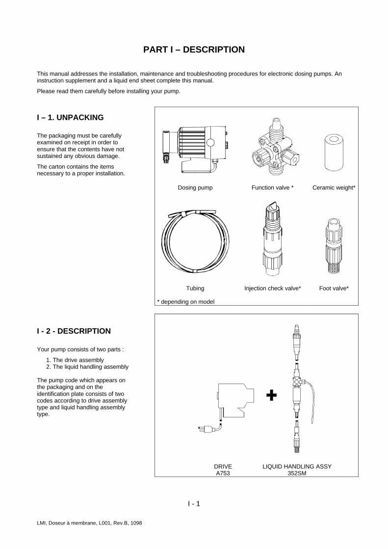
I – 1. UNPACKING
The packaging must be carefullyexamined on receipt in order toensure that the contents have notsustained any obvious damage.
The carton contains the itemsnecessary to a proper installation.
I - 2 - DESCRIPTION
Your pump consists of two parts :
1. The drive assembly2. The liquid handling assembly
The pump code which appears onthe packaging and on theidentification plate consists of twocodes according to drive assemblytype and liquid handling assemblytype.
Dosing pump Function valve * Ceramic weight*
Tubing Injection check valve* Foot valve*
* depending on model
DRIVEA753
LIQUID HANDLING ASSY352SM

I - 2
LMI, Doseur à membrane, L001, Rev.B, 1098
Output adjustment controlsAccording to pump type, output adjustment controls areavailable :
• Stroke adjustmentEach pump is equipped with a stroke adjustment.Stroke control provides adjustment of percent ofmaximum diaphragm travel.
Note : For B & C Series, stroke adjustment only whenpump is running.
• Speed adjustmentA1, A7, B1, B7, C1, C7, J5, P1 Series pumps areequipped with a speed adjustment. Speed controlprovides adjustment of the percent of maximum strokesper minute.
• Pressure control adjustmentB7 and C7 Series Pumps are equipped with a pressurecontrol adjustment. Pressure control provides theadjustment of the pump’s pressure capability and powerconsumption, reducing heat, pipe shock and pulsation.
For more details, refer to Instruction supplement
I - 3. ACCESSORIES
4-Function valveThis accessory is supplied as standard equipment or asoption. The functions are :
1. Anti-syphon (automatic)Prevents syphoning when pumping downhill or into avacuum.
2. Back pressure (automatic)Supply approximately 1,7 bar back pressure to preventover pumping when little or no system back pressure ispresent.
3. Priming (manual)Prime your pump while it is connected to a pressurizedline.
4. Line depressurization (manual)By pulling both knobs (yellow and black) the dischargeline will drain back to your supply tank.
3-Function valveThis accessory is supplied as standard equipment or asoption (according to Series 300 models). The functionsare :
1. Priming (manual)Prime your pump while it is connected to a pressurizedline.
2. Pressure relief (automatic)Provides protection against excessive system pressure.
3. Line depressurization (manual)By opening the relief valve, the discharge line willdepressurize without having loosen or disconnectdischarge tubing.
Bleed/4-Function valveThis accessory is supplied as standard equipment or asoption (according to Series 300 models). The functionsare :
1. Anti-syphon (automatic)Prevents syphoning when pumping downhill orinto a vacuum.
2. Back pressure (automatic)Supply approximately 1,7 bar back pressure toprevent over pumping when little or no systemback pressure is present.
3. Continuous bleed (automatic)This valve is designed to permit an adjustable,continuous bleed or degasing or entrappedvapors. It is ideal for pumping small volumes ofsolutions having low vapor pressures.
4. Line depressurization (manual)By opening bleed port, the discharge lline willdepressurize, without having to loosen tubing orfittings.
Foot valve (Accessory available according to the model)
The foot valve makes easier priming and keep thepump primed in suction lift applications.
The strainer prevents sediment to pass through andvalves to clog.
Injection check valveCanne d’injectionThe injection check valve prevents backflow from atreated line.
I – 4. PRECAUTIONSAlways wear protective clothing, face shield, safetyglasses and gloves when working on or near yourmetering pump.
All LMI pumps are shipped from factory with waterin pump head to make easier priming.
If the pump head is empty, refill it with water orsolution compatible with pumped solution beforestarting up the pump (see note on the Liquid EndSheet).
Solution compatibilityVerify that the liquid handling components arecompatible with the pumped solution (refer to LiquidEnd Sheet).
Make certain that all tubing is securely attached tofittings prior to start-up.
Tubing supplied allows to match with pumpmaximum specifications.
All fittings should be hand tightened.Overtighteningor use of a pipe wrench can cause damage to thefittings, causing the pump to lose prime or notfunction.
All LMI pumps have straight ¾’’- 16N or 7/8 ’’- 14Nor 1"- 12 N machine threads on the head andfittings.
The seal rings prevent leaks. Do not use Teflon tapebetween fittings and pump head.

II - 1
LMI, Doseur à membrane, L001, Rev.B, 1098
PART II – INSTALLATION
II – 1. HYDRAULIC INSTALLATION
The pump can be mounted in one of two ways :
• Flooded suction (ideal installation).• Suction lift – when suction lift is less than 1,5 m for
solutions having a specific gravity of water. YourLMI metering pump must be mounted so that thesuction and discharge valves are vertical.
Flooded suctionThe pump is mounted at the base of the storage tank.
This installation is the most trouble-free, and isrecommended for very low outputs, solutions thatgasify, and high viscosity solutions. (Install shut offvalve on the tank).
1 Solution tank 9 Vent4 Pump 10 Tee8 Injection check valve
Fig. 2.1a : Flooded suction
Suction lift• Wall bracket mount. The pump
may be mounted directly above thesolution tank. A pump mounted inthis manner allows for easychanging of solution tank.
1 Solution tank4 Pump6 Pressure line8 Injection check valve
10 TeeA 50 mm space for
sediment accumulation
Fig. 2.1b : Suction lift

II - 2
LMI, Doseur à membrane, L001, Rev.B, 1098
• Tank mount. The pump may bemounted on a molded tank. Tanksfrom 60 to 1000 liters are availablefor this utilisation.
1 Solution tank2 Foot valve (equipped
with strainer)4 Pump6 Flow8 Injection check valve
10 Te11 Ceramic weightA 50 mm space for
sediment accumulation
• Shelf mount (customer supplied).The pump may be mounted on ashelf. An LMI mounting kit isavailable for securing the pump toa shelf. (Series A , B, C).
1 Solution tank2 Foot valve (equipped
with strainer)4 Pump6 Flow8 Injection check valve
10 Te11 Ceramic weightA 50 mm space for
sediment accumulation
Fig. 2.1c : Tank mount
Fig. 2.1d : Shelf mount

II - 10 LMI, Doseur à membrane, L002, Rev.B, 1098
Pump location Locate pump in an area convenient to solution tank and electrical supply. The pump should not be subjected to ambient temperatures above 50°C. Avoid exposing to direct sunlight the pump. Tubing connections
• For installation and trouble-free running, use only recommended tubing size (refer to spare parts list). • Do not use clear vinyl tubing on the discharge side of the pump. The pressure created by the pump can rupture the vinyl tubing. • Before installation, all tubing must be cut with a clean square end.
• Remove the plugs which protect the head connections and valves. • Do not use pliers or pipe wrench on coupling nuts or fittings.
Refer also to the Liquid End Sheet. Foot valve/Ceramic weight The foot valve must be sit in a vertical position at the bottom. Position approximately 50 mm off the bottom if the tank or drum contains sediment. The ceramic weight positions the foot valve in a vertical position. Refer to the Liquid End Sheet for details of connections
1 Solution tank 4 Pump 2 Foot valve 11 Ceramic weight
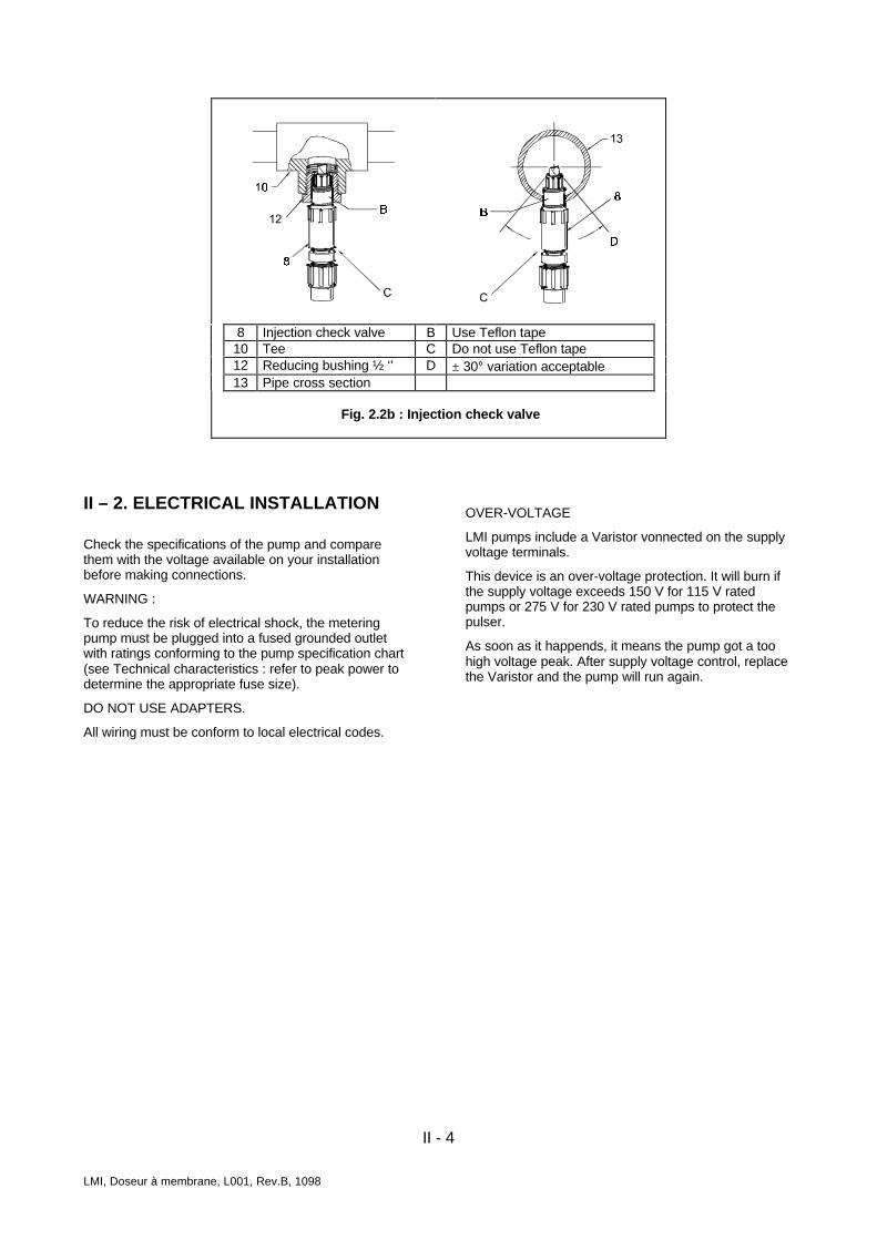
Fig. 2.2a : Foot valve/Ceramic weight Injection check valveCanne d’injection Connect the injection check valve to your discharge (outlet) line (refer to the Liquid End Sheet). For in-line injection, use fitting or pipe tee with reducing bushing to ½’’ (12x17). Use Teflon tape or pipe dope to seal the pipe threads only.
When installing the injection check valve, be sure to position it so that the valve enters the botton of your pipe in a vertical position (see fig. 2.2b). Variations left and right within 30° are acceptable. For low pressure (under 1,7 bar) or open tank use, the injection nozzle prevents siphoning but not flow increase. In this case,we recommend the use of a 4-Function valve. Refer to the Liquid End Sheet for details of connections.
II - 4
LMI, Doseur à membrane, L001, Rev.B, 1098
8 Injection check valve B Use Teflon tape10 Tee C Do not use Teflon tape12 Reducing bushing ½ ‘’ D ± 30° variation acceptable13 Pipe cross section
Fig. 2.2b : Injection check valve
II – 2. ELECTRICAL INSTALLATION
Check the specifications of the pump and comparethem with the voltage available on your installationbefore making connections.
WARNING :
To reduce the risk of electrical shock, the meteringpump must be plugged into a fused grounded outletwith ratings conforming to the pump specification chart(see Technical characteristics : refer to peak power todetermine the appropriate fuse size).
DO NOT USE ADAPTERS.
All wiring must be conform to local electrical codes.
OVER-VOLTAGE
LMI pumps include a Varistor vonnected on the supplyvoltage terminals.
This device is an over-voltage protection. It will burn ifthe supply voltage exceeds 150 V for 115 V ratedpumps or 275 V for 230 V rated pumps to protect thepulser.
As soon as it happends, it means the pump got a toohigh voltage peak. After supply voltage control, replacethe Varistor and the pump will run again.
III - 1
LMI, Doseur à membrane, L001, Rev.B, 1098
PART III – START UP
Pumps are shipped from the factory with water in thepump head to aid in priming. After a long storage, refillthe pump head with water or solution compatible withpumped solution (see note on the Liquid End Sheet).
III – 1. PRIMING
After connecting the pump, plug in or switch the pumpon. While the pump is running, set the speed knob at80% and the stroke knob at 100%. If the pump isequipped with a pressure control knob (B7, C7), set theswitch on « INTERNAL » and turn the pressure controlknob fully clockwise.
III – 2. OUTPUT ADJUSTMENTCONTROLS
Once the pump has been primed, an appropriate outputadjustment must be made.
The identification plate indicates the output at max.stroke and max. speed (100%) and max. pressure. Thegraduations of stroke knob and speed knob correspondto percentage of this max. output.
Note : P0 pumps have no stroke adjustment.
Example :
Use max. output = 2,3 L/H. If the pump is set at 40%speed and 60% stroke lenght, the appropriate pump output is 2,3 L/H x 0.40 x 0.60 = 0,55 L/H.
Note : Remember that 6x8 tubing is 0,22 ml/cm which is0,8 % wrong for 1 l measuring pot.
III – 3. CALIBRATION
Once installation is complete and the approximateoutput has been determined, the pump should becalibrated to adjust speed and stroke for your actualdesired output.
1. If equipped (B7 – C7 series), make certain Pressurecontrol knob is turned fully clockwise.
2. Be sure the pump is in normal service (i.e. includingfactors such as injection pressure, fluid viscosity,suction lift …).
3. Place the foot valve in a graduated container.4. Start the pump at maximum frequency and let it run
to remove air trapped in suction line (bleed valveopen when using a 4FV). Close bleed after priming.
5. Turn the pump off. Refill graduated container to alevel strarting point.
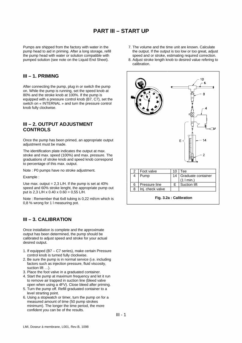
6. Using a stopwatch or timer, turn the pump on for ameasured amount of time (50 pump strokesminimum). The longer the time period, the moreconfident you can be of the results.
7. The volume and the time unit are known. Calculatethe output. If the output is too low or too great, adjustspeed and or stroke, estimating required correction.
8. Adjust stroke length knob to desired value refering tocalibration.
2 Foot valve 10 Tee4 Pump 14 Graduate container
(1 l min.)6 Pressure line E Suction lift8 Inj. check valve
Fig. 3.2a : Calibration
III - 2
LMI, Doseur à membrane, L001, Rev.B, 1098
III – 4. VOLUMETRIC CALIBRATION INEXTERNAL MODE
1. Since pump output is governed by an external devicesuch as Flowmeter-pulser, Liquitron Current-to-frequency converter or 4-20 mA DC signal from aninstrument with an LMI Analog-to-digital converter,only the ouptut per stroke may be calibrated.
2. With pump primed and discharge tubin connected tothe injection point as it would be in normal service,place foot valve in a graduated container.
3. Swtch pump to Internal mode with speed knob set at100 until air is exhausted from suction line and pumphead.
4. Adjust control pressure (B7 – C7 series).5. Turn the pump off. Refill graduated container to a
level strarting point.6. Switch pump on and count the number of strokes.
For a good accuracy, count at least 100 strokes.Switch pump off.
7. Note the volume pumped during the calibrationperiod and the number of strokes. Divide into thevolume the number of strokes to determine thevolume of solution pumped per stroke.
8. Adjust stroke length knob to desired value refering tocalibration.
III – 5. PRESSURE CONTROL
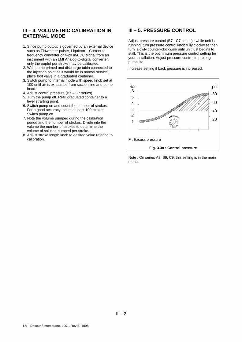
Adjust pressure control (B7 - C7 series) : while unit isrunning, turn pressure control knob fully clockwise thenturn slowly counter-clockwise until unit just begins tostall. This is the optimmum pressure control setting foryour installation. Adjust pressure control to prolongpump life.
Increase setting if back pressure is increased.
F : Excess pressure
Fig. 3.3a : Control pressure
Note : On series A9, B9, C9, this setting is in the mainmenu.
IV - 1
IV – MAINTENANCE
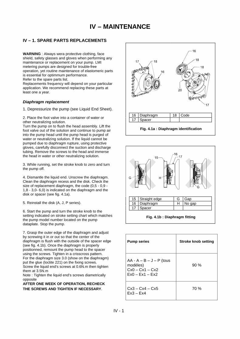
IV – 1. SPARE PARTS REPLACEMENTS WARNING : Always wera protective clothing, face shield, safety glasses and gloves when performing any maintenance or replacement on your pump. LMI metering pumps are designed for trouble-free operation, yet routine maintenance of elastomeric parts is essential for optimmum performance. Refer to the spare parts list. Replacements frequency will depend on your particular application. We recommend replacing these parts at least one a year. Diaphragm replacement 1. Depressurize the pump (see Liquid End Sheet). 2. Place the foot valve into a container of water or other neutralizing solution. Turn the pump on to flush the head assembly. Lift the foot valve out of the solution and continue to pump air into the pump head until the pump head is purged of water or neutralizing solution. If the liquid cannot be pumped due to diaphragm rupture, using protective gloves, carefully disconnect the suction and discharge tubing. Remove the screws to the head and immerse the head in water or other neutralizing solution. 3. While running, set the stroke knob to zero and turn the pump off. 4. Dismantle the liquid end. Unscrew the diaphragm. Clean the diaphragm recess and the disk. Check the size of replacement diaphragm, the code (0,5 - 0,9 - 1,8 - 3,0- 6,0) is indicated on the diaphragm and the disk or spacer (see fig. 4.1a). 5. Reinstall the disk (A, J, P series). 6. Start the pump and turn the stroke knob to the setting indicated on stroke setting chart which matches the pump model number located on the pump dataplate. Stop the pump. 7. Grasp the outer edge of the diaphragm and adjust by screwing it in or out so that the center of the diaphragm is flush with the outside of the spacer edge (see fig. 4.1b). Once the diaphragm is properly positionned, remount the pump head to the spacer using the screws. Tighten in a crisscross pattern. For the diaphragm size 3.0 (show on the diaphragm) put the glue (loctite 221) on the fixing screws. Screw the liquid end’s screws at 0.6N.m then tighten them at 3.5N.m Note : Tighten the liquid end’s screws diametrically opposite AFTER ONE WEEK OF OPERATION, RECHECK THE SCREWS AND TIGHTEN IF NECESSARY.
16 Diaphragm 18 Code 17 Spacer
Fig. 4.1a : Diaphragm identification
15 Straight edge G Gap 16 Diaphragm H No gap 17 Spacer
Fig. 4.1b : Diaphragm fitting
Pump series
Stroke knob setting
AA - A – B – J – P (tous modèles) Cx0 – Cx1 – Cx2 Ex0 – Ex1 – Ex2
90 %
Cx3 – Cx4 – Cx5 Ex3 – Ex4
70 %
IV - 2
LMI, Doseur à membrane, L001, Rev.B, 1098
Ball, seal ring and injection check valve springreplacement or set of cartridges replacement(depending on model)
Refer to the spare parts list for the proper sparte partskit number.
1. Depressurize the pump (see Liquid End Sheet).2. Flush and purg the pump head before dismantling
(see above).3.During dismantling, note the orientation of each item.4. Dismantling the injection check valve. Unscrew the
valve body and replace the spring, the ball and theseal ring. Refer to the spare parts list drawing.
5. Replace the seal rings and balls in the pump headand the foot valve. Order of assembly changesdepending on valve location.
6. In case of cartridge liquid end, see spare parts listdrawing to identify the orientation of each item.
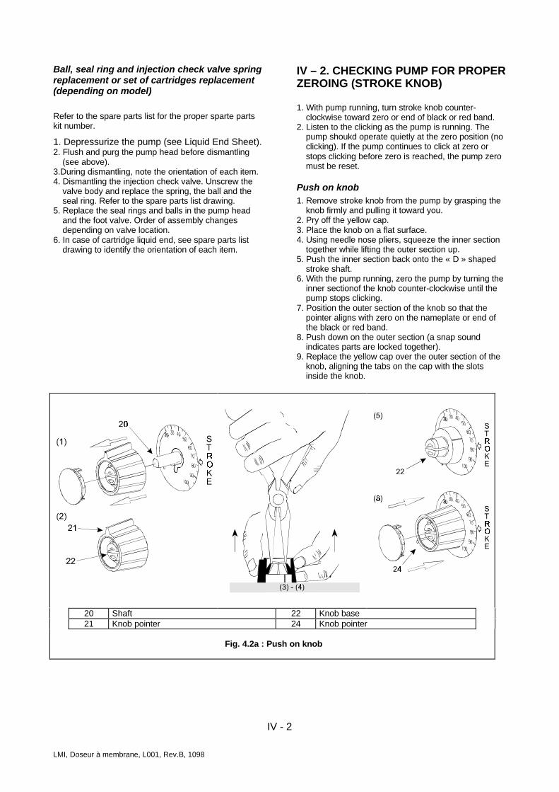
IV – 2. CHECKING PUMP FOR PROPERZEROING (STROKE KNOB)
1. With pump running, turn stroke knob counter-clockwise toward zero or end of black or red band.
2. Listen to the clicking as the pump is running. Thepump shoukd operate quietly at the zero position (noclicking). If the pump continues to click at zero orstops clicking before zero is reached, the pump zeromust be reset.
Push on knob1. Remove stroke knob from the pump by grasping the
knob firmly and pulling it toward you.2. Pry off the yellow cap.3. Place the knob on a flat surface.4. Using needle nose pliers, squeeze the inner section
together while lifting the outer section up.5. Push the inner section back onto the « D » shaped
stroke shaft.6. With the pump running, zero the pump by turning the
inner sectionof the knob counter-clockwise until thepump stops clicking.
7. Position the outer section of the knob so that thepointer aligns with zero on the nameplate or end ofthe black or red band.
8. Push down on the outer section (a snap soundindicates parts are locked together).
9. Replace the yellow cap over the outer section of theknob, aligning the tabs on the cap with the slotsinside the knob.
20 Shaft 22 Knob base21 Knob pointer 24 Knob pointer
Fig. 4.2a : Push on knob

IV - 3
LMI, Doseur à membrane, L001, Rev.B, 1098
IV – 3. TROUBLESHOOTING
Pump will not prime• Pump not turned on or plugged in.
Turn on pump/plug in pump.
• Output dials not set properly.Always prime pump with speed at 80 % and strokeat 100 %.
• Foot valve not in vertical position on bottom of tank.See Chapter II – 1. Section Foot valve/ceramicweight.
• Pump suction lift too high.Maximum suction lift is 1,5 m. Pump with Highviscosity liquid handling assemblies require floodedsuction.
• Suction tubing is curved or coiled in tank.Suction tubing must be vertical. Use ceramic weightsupplied with pump. (see Chapter II – 1. SectionFoot valve/ceramic weight).
• Fittings are over tightened.Do not overtighten fittings. This causes seal rings todistort and not seat propertly which causes pump toleak back or lose prime.
• Air trap in suction valve tubing.Suction tubing should be as vertical as possible.AVOID FALSE FLOODED SUCTION (see ChapterII – 1. Section Flooded suction).
• Too much pressure at discharge (pump without 4-function valve).Shut off valves in pressurized line. Disconnecttubing at injection check valve (see Chapter III – 1.Priming). When pump is primed, reconnectdischarge tubing.
Pump loses prime• Solution container ran dry.
Refill container with solution and reprime (see PartIII).
• Foot valve not in vertical position on bottom of tank.See Chapter II – 1. Section Foot valve/ceramicweight.
• Pump suction lift too high.Maximum suction lift is 1,5 m. Pump with Highviscosity liquid handling assemblies require floodedsuction.
• Suction tubing is curved or coiled in tank.Suction tubing must be vertical. Use ceramic weightsupplied with pump. (see Chapter II – 1. SectionFoot valve/ceramic weight).
• Fittings are over tightened.Do not overtighten fittings. This causes seal rings todistort and not seat propertly which causes pump toleak back or lose prime.
• Air trap in suction valve tubing.Suction tubing should be as vertical as possible.AVOID FALSE FLOODED SUCTION (see ChapterII – 1. Section Flooded suction).
• Air leak on suction side.Check for pinholes, cracks. Replace if necessary.
Leakage at tubing• Worn tubing ends.
Cut tubing about 25 mm (1’’) off tubing and thenreplace as before.
• Loose or crack fitting.Replace fitting if cracked. Carefully hand tightenfittings. Do not use pipe wrench. Once fitting comesinto contact with seal ring, tighten an additional 1/8or ¼ turn.
• Worn seal rings.Replace balls and seal rings (see part IV).
• Solution attacking Liquid handling assemblymaterial.Consult Technical Assistance Department foralternate materials compatible with the pumpedsolution.
Low output or failure to pump againstpressure• Pump’s maximum pressure rating is exceeded by
injection pressure.Injection pressure cannot exceed pump’s maximumpressure. See pump data plate.
• Worn seal rings.Replace them : see Chapter IV –1.
• Ruptured diaphragm.Replace diaphragm : see Chapter IV –1. SectionDiaphragm replacement.
• Incorrect stroke length.Check zero on pump/Re-zero pump (See ChapterIV – 2.).
• Tubing run on discharge may be too long.Longer tubing runs may create frictional lossessufficient to reduce pump’s pressure rating.
• Clogged foot valve strainer.Remove foot valve strainer when pumping slurriesor when solution particles cause strainer to clog.
Failure to run• Pump not turned on or plugged in.
Turn on or plug in pump. Check also programming(A9, B9, C9 Series).
• EPU failure.Disassemble pump and measure the resistance ofthe EPU across the EPU wires. Resistance readingshould be in accordance to the table (see ChapterIV – 4.). Also check EPU leads to ground.
• Pulser failure.The pulser should be replaced if EPU checks outOK.

IV - 4
LMI, Doseur à membrane, L001, Rev.B, 1098
Excessive pump output• Syphoning. Pumping downhill without a 4-FV.
Move injection point to a pressurized location orinstall an 4-FV.
• Little or no pressure at injection point.If pressure at injection point is less than 1,5 bar (25psi), an 4-FV should be installed.
• Excessive strokes per minute.Replace pulser or control panel.
IV – 4. EPU RESISTANCE CHART
Pump series Voltage Coil resistance (ohms)20° C (68°F)
Ax4, Ax5, Ax6 115 V 76 – 87Px4, Px5, Px6, Px8H9
230 V 307 – 353
Ax7, Ax8 115 V 152 – 176Px2, Px3 230 V 583 – 671
Bx1, Bx2, Bx3, Bx4 115 V 43 –49230 V 167 – 193
Cx0, Cx1, Cx2, Cx3, Cx4, Cx5 115 V 22.8 – 26,2E70, E71, E72, E73, E74 230 V 91 – 105
J54D, J55D, J56D 12VDC 1.1 – 1.3
Instruction Supplement LMI PUMP SERIES P1
Date : 10.98 Replaces Rev. 0 , 07.98
REF. : 161.5304.001 Rev. A
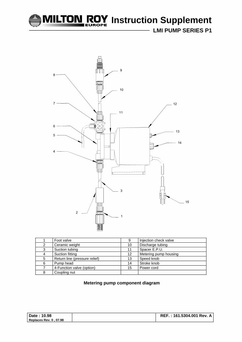
1 Foot valve 9 Injection check valve 2 Ceramic weight 10 Discharge tubing 3 Suction tubing 11 Spacer E.P.U. 4 Suction fitting 12 Metering pump housing 5 Return line (pressure relief) 13 Speed knob 6 Pump head 14 Stroke knob 7 4-Function valve (option) 15 Power cord 8 Coupling nut
Metering pump component diagram
LMI PUMP SERIES P1 2/3
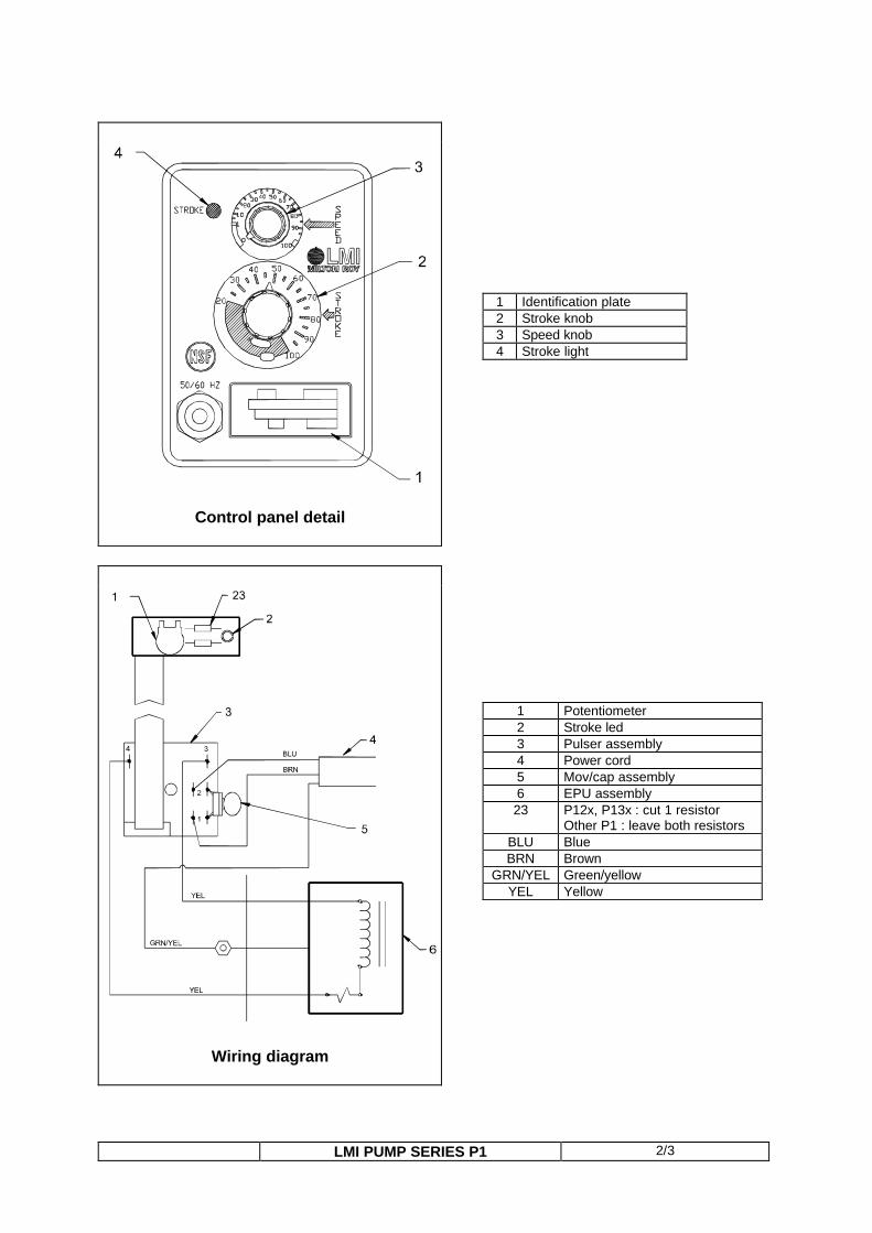
Control panel detail
Wiring diagram
1 Identification plate 2 Stroke knob 3 Speed knob 4 Stroke light
1 Potentiometer 2 Stroke led 3 Pulser assembly 4 Power cord 5 Mov/cap assembly 6 EPU assembly 23 P12x, P13x : cut 1 resistor
Other P1 : leave both resistors BLU Blue BRN Brown
GRN/YEL Green/yellow YEL Yellow
LMI PUMP SERIES P1 3/3
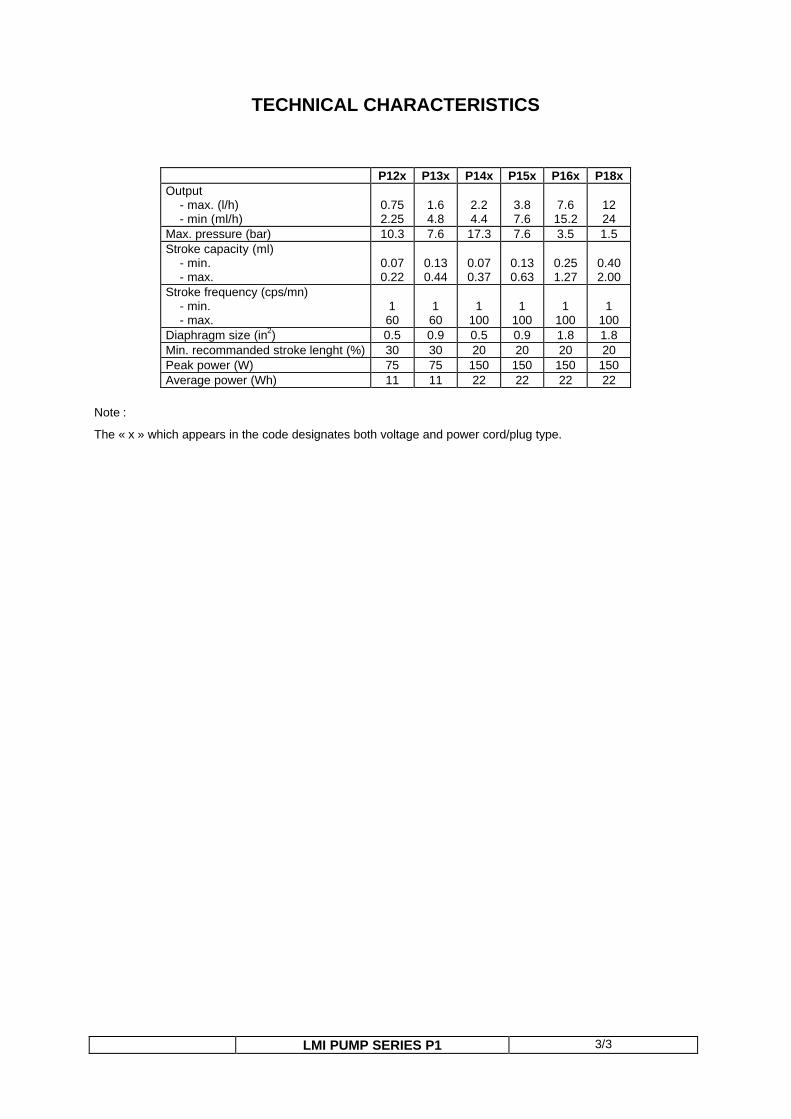
TECHNICAL CHARACTERISTICS
P12x P13x P14x P15x P16x P18x Output - max. (l/h) - min (ml/h)
0.75 2.25
1.6 4.8
2.2 4.4
3.8 7.6
7.6 15.2
12 24
Max. pressure (bar) 10.3 7.6 17.3 7.6 3.5 1.5 Stroke capacity (ml) - min. - max.
0.07 0.22
0.13 0.44
0.07 0.37
0.13 0.63
0.25 1.27
0.40 2.00
Stroke frequency (cps/mn) - min. - max.
1 60
1 60
1
100
1
100
1
100
1
100 Diaphragm size (in2) 0.5 0.9 0.5 0.9 1.8 1.8 Min. recommanded stroke lenght (%) 30 30 20 20 20 20 Peak power (W) 75 75 150 150 150 150 Average power (Wh) 11 11 22 22 22 22
Note :
The « x » which appears in the code designates both voltage and power cord/plug type.
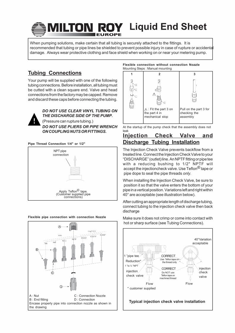
Pipe Thread Connection 1/4" or 1/2"
Typical injection check valve installation
Liquid End Sheet
1 ”pipe tee Reduction*1 ”to ½ ”NPT
injectioncheck valve
CORRECTUse Teflon tape on
the thread only
CORRECTDo NOT useTeflon tape on
machined thread
injectioncheckvalve
Flow Flow
40°Variationacceptable
* customer supplied
NPT pipeconnection
DO NOT USE CLEAR VINYL TUBING ONTHE DISCHARGE SIDE OF THE PUMP.(Pressure can rupture tubing.)DO NOT USE PLIERS OR PIPE WRENCHON COUPLING NUTS OR FITTINGS.
Tubing ConnectionsYour pump will be supplied with one of the followingtubing connections. Before installation, all tubing mustbe cutted with a clean square end. Valve and headconnections from the factory may be capped. Removeand discard these caps before connecting the tubing.
Apply Teflon© tape.(Customer supplied pipe
connections)
Injection Check Valve andDischarge Tubing InstallationThe Injection Check Valve prevents backflow from atreated line. Connect the Injection Check Valve to your“DISCHARGE” (outlet) line. An NPTF fitting or pipe teewith a reducing bushing to 1/2" NPTF will accept the injectioncheck valve. Use Teflon® tape or pipe dope to seal the pipe threads only.
When installing the Injection Check Valve, be sure to position it so that the valve enters the bottom of yourpipe in a vertical position. Variations left and right within40° are acceptable (see illustration below).
After cutting an appropriate length of discharge tubing,connect tubing to the injection check valve then backdischarge
Make sure it does not crimp or come into contact with hot or sharp surface (see Tubing Connections).
When pumping solutions, make certain that all tubing is securely attached to the fittings. It isrecommended that tubing or pipe lines be shielded to prevent possible injury in case of rupture or accidentaldamage. Always wear protective clothing and face shield when working on or near your metering pump.
Flexible pipe connection with connection Nozzle
A : Nut C : Connection NozzleB : End fitting D : ConnectionEncase properly pipe into connection nozzle as shown inthe drawing
Flexible connection without connection NozzleMounting Steps : Manual mounting
1
At the startup of the pump check that the assembly does notleak
2
: Fit the part 3 onthe part 4 inmechanical stop
3
Pull on the part 3 forchecking theassembly
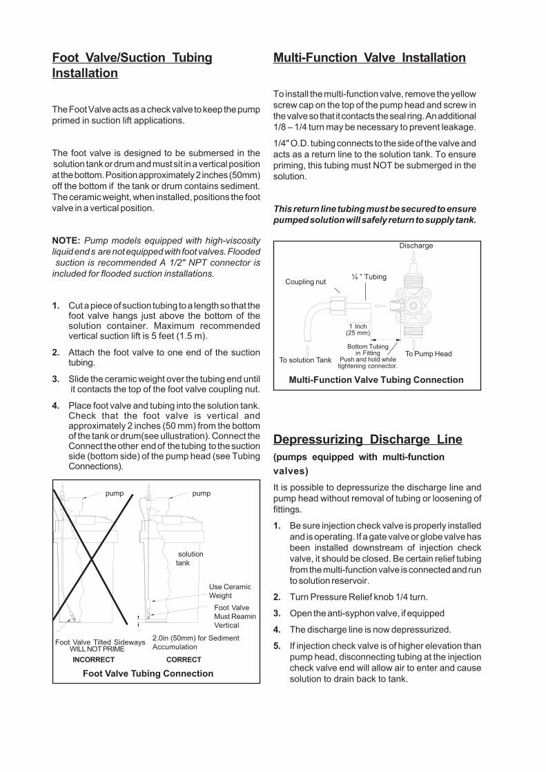
Use CeramicWeight
pump pump
Foot ValveMust ReaminVertical
CORRECTINCORRECT
2.0in (50mm) for SedimentAccumulation
solutiontank
Foot Valve Tilted Sideways
Foot Valve Tubing Connection
WILL NOT PRIME
Foot Valve/Suction TubingInstallation
The Foot Valve acts as a check valve to keep the pumpprimed in suction lift applications.
The foot valve is designed to be submersed in the solution tank or drum and must sit in a vertical positionat the bottom. Position approximately 2 inches (50mm)off the bottom if the tank or drum contains sediment.The ceramic weight, when installed, positions the footvalve in a vertical position.
NOTE: Pump models equipped with high-viscosityliquid end s are not equipped with foot valves. Flooded suction is recommended A 1/2" NPT connector isincluded for flooded suction installations.
1. Cut a piece of suction tubing to a length so that thefoot valve hangs just above the bottom of thesolution container. Maximum recommendedvertical suction lift is 5 feet (1.5 m).
2. Attach the foot valve to one end of the suctiontubing.
3. Slide the ceramic weight over the tubing end until it contacts the top of the foot valve coupling nut.
4. Place foot valve and tubing into the solution tank.Check that the foot valve is vertical andapproximately 2 inches (50 mm) from the bottomof the tank or drum(see ullustration). Connect theConnect the other end of the tubing to the suctionside (bottom side) of the pump head (see TubingConnections).
Multi-Function Valve Installation
To install the multi-function valve, remove the yellowscrew cap on the top of the pump head and screw inthe valve so that it contacts the seal ring. An additional1/8 – 1/4 turn may be necessary to prevent leakage.
1/4" O.D. tubing connects to the side of the valve andacts as a return line to the solution tank. To ensurepriming, this tubing must NOT be submerged in thesolution.
This return line tubing must be secured to ensurepumped solution will safely return to supply tank.
Depressurizing Discharge Line(pumps equipped with multi-functionvalves)It is possible to depressurize the discharge line andpump head without removal of tubing or loosening offittings.
1. Be sure injection check valve is properly installedand is operating. If a gate valve or globe valve hasbeen installed downstream of injection checkvalve, it should be closed. Be certain relief tubingfrom the multi-function valve is connected and runto solution reservoir.
2. Turn Pressure Relief knob 1/4 turn.
3. Open the anti-syphon valve, if equipped
4. The discharge line is now depressurized.
5. If injection check valve is of higher elevation thanpump head, disconnecting tubing at the injectioncheck valve end will allow air to enter and causesolution to drain back to tank.
Discharge
To Pump Head
¼ ” TubingCoupling nut
To solution Tank
Bottom Tubingin Fitting
Push and hold whiletightening connector.
1 Inch(25 mm)
Multi-Function Valve Tubing Connection
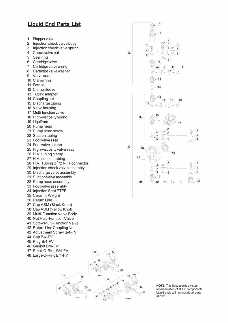
1 Flapper valve2 Injection check valve body3 Injection check valve spring4 Check valve ball5 Seal ring6 Cartridge valve7 Cartridge valve o-ring8 Cartridge valve washer9 Valve seat10 Clamp ring11 Ferrule12 Clamp sleeve13 Tubing adapter14 Coupling nut15 Discharge tubing16 Valve housing17 Multi-function valve18 High-viscosity spring19 Liquifram20 Pump head21 Pump head screw22 Suction tubing23 Foot valve seat24 Foot valve screen25 High-viscosity valve seat26 H.V. tubing clamp27 H.V. suction tubing28 H.V. Tubing x 1/2 NPT connector29 Injection check valve assembly30 Discharge valve assembly31 Suction valve assembly32 Pump head assembly33 Foot valve assembly34 Injection Seat PTFE35 Ceramic Weight36 Return Line37 Cap ASM (Black Knob)38 Cap ASM (Yellow Knob)39 Multi-Function Valve Body40 Nut Multi-Function Valve41 Screw Multi-Function Valve42 Return Line Coupling Nut43 Adjustment Screw B/4-FV44 Cap B/4-FV45 Plug B/4-FV46 Gasket B/4-FV47 Small O-Ring B/4-FV48 Large O-Ring B/4-FV
Liquid End Parts List
NOTE: This illustration is a visualrepresentation of all LE components.Liquid ends will not include all partsshown.
40 42
40
36
38
3948
4746
4544
4143
41
4236
41
3937
1717
17
3739
3840
42
36
3FV B/4FV
4FV
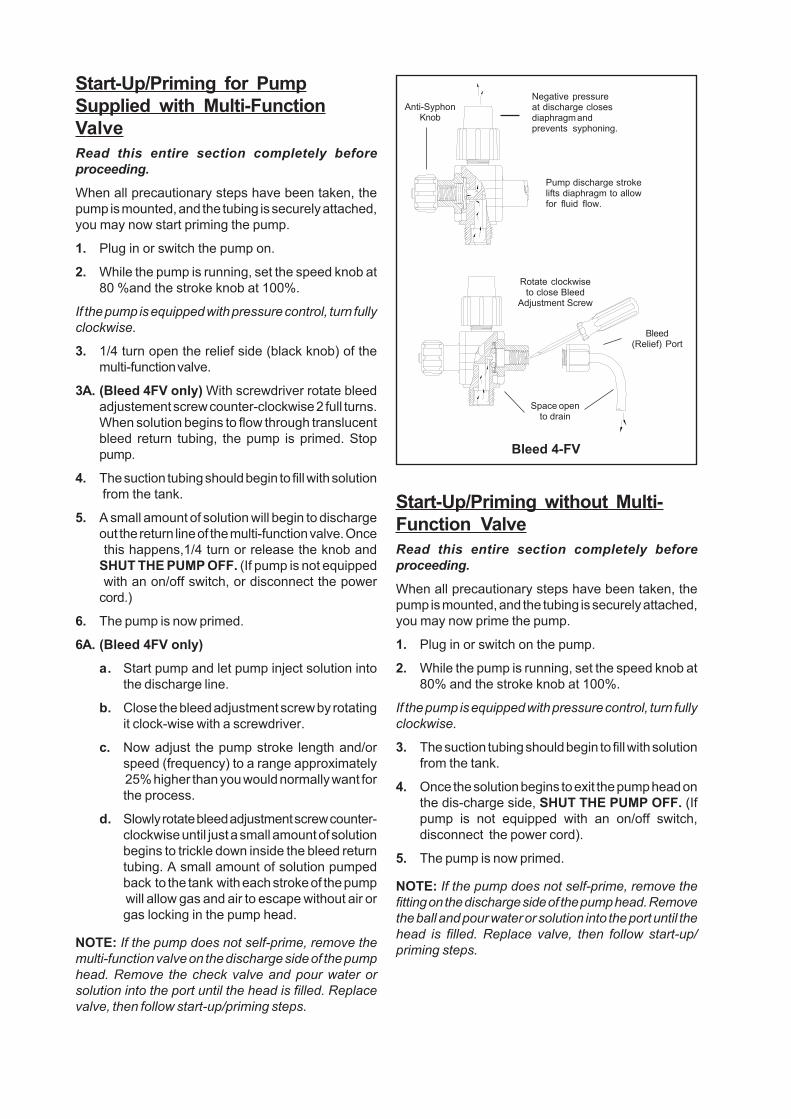
Bleed 4-FV
Start-Up/Priming for PumpSupplied with Multi-FunctionValveRead this entire section completely beforeproceeding.
When all precautionary steps have been taken, thepump is mounted, and the tubing is securely attached,you may now start priming the pump.
1. Plug in or switch the pump on.
2. While the pump is running, set the speed knob at80 %and the stroke knob at 100%.
If the pump is equipped with pressure control, turn fullyclockwise.
3. 1/4 turn open the relief side (black knob) of themulti-function valve.
3A. (Bleed 4FV only) With screwdriver rotate bleedadjustement screw counter-clockwise 2 full turns.When solution begins to flow through translucentbleed return tubing, the pump is primed. Stoppump.
4. The suction tubing should begin to fill with solution from the tank.
5. A small amount of solution will begin to dischargeout the return line of the multi-function valve. Once this happens,1/4 turn or release the knob andSHUT THE PUMP OFF. (If pump is not equipped with an on/off switch, or disconnect the powercord.)
6. The pump is now primed.
6A. (Bleed 4FV only)
a. Start pump and let pump inject solution intothe discharge line.
b. Close the bleed adjustment screw by rotatingit clock-wise with a screwdriver.
c. Now adjust the pump stroke length and/orspeed (frequency) to a range approximately 25% higher than you would normally want forthe process.
d. Slowly rotate bleed adjustment screw counter-clockwise until just a small amount of solutionbegins to trickle down inside the bleed returntubing. A small amount of solution pumpedback to the tank with each stroke of the pump will allow gas and air to escape without air orgas locking in the pump head.
NOTE: If the pump does not self-prime, remove themulti-function valve on the discharge side of the pumphead. Remove the check valve and pour water orsolution into the port until the head is filled. Replacevalve, then follow start-up/priming steps.
Start-Up/Priming without Multi-Function ValveRead this entire section completely beforeproceeding.
When all precautionary steps have been taken, thepump is mounted, and the tubing is securely attached,you may now prime the pump.
1. Plug in or switch on the pump.
2. While the pump is running, set the speed knob at80% and the stroke knob at 100%.
If the pump is equipped with pressure control, turn fullyclockwise.
3. The suction tubing should begin to fill with solutionfrom the tank.
4. Once the solution begins to exit the pump head onthe dis-charge side, SHUT THE PUMP OFF. (Ifpump is not equipped with an on/off switch,disconnect the power cord).
5. The pump is now primed.
NOTE: If the pump does not self-prime, remove thefitting on the discharge side of the pump head. Removethe ball and pour water or solution into the port until thehead is filled. Replace valve, then follow start-up/priming steps.
Rotate clockwiseto close Bleed
Adjustment Screw
Anti-SyphonKnob
Negative pressureat discharge closesdiaphragm andprevents syphoning.
Bleed(Relief) Port
Space opento drain
Pump discharge strokelifts diaphragm to allowfor fluid flow.
F
DECLARATION "CE" DE CONFORMITE Nous, déclarons que le matériel désigné ci-après a été conçu et fabriqué suivant les directives et spécifications suivantes : Directive basse tension 2006/95/EEC
Directive CEM 2004/108/EEC
GB "EC" DECLARATION OF CONFORMITY
We, certify that the equipment designated below has been designed and manufactured in accordance with the specifications of the following : Low voltage Directive 2006/95/EEC
EMC Directive 2004/108/EEC
D EG-KONFORMITÄTSERKLÄRUNG
Wir, verklären, daß die nachgestehend bezeichneten Gerätschaften im Einklang mit folgenden Richtlinien und Spezifikationen geplant und hergestellt wurden : EG-Richtlinie 2006/95 für Niederspannung
EG-Richtlinie 2004/108 zur elektromagnetischen Verträglichkeit
NL EG FABRIKANTENCONFORMVERKLARING
De ondergetekenden, verklaren geheel onder eigen verantwoordelijkheid dat het produkt waarop deze verklaring betrekking heeft in overeenstemming is met: Richtlijn 2006/95/EEG inzake elektrisch materiaal bestemd voor gebruik binnen bepaalde spanningsgrenzen;
Richtlijn 2004/108/EEG inzake elektromagnetische compatibiliteit. I
DICHIARAZIONE DI CONFORMITA' "CE" La società, Dichiara che il materiale sotto specificato è stato progettato e realizzato in conformità con le seguenti direttive e specifiche: Direttiva bassa tensione 2006/95/EEC
Direttiva CEM 2004/108/EEC
E DECLARACION "CE" DE CONFORMIDAD
Nosotros, declaramos que el material detallado a continuación está diseñado y fabricado de acuerdo a la siguientes directivas y normas : Directiva basa tensión 2006/95/EEC
Directiva EMC 2004/108/EEC
TYPE / TYP / TIPO LMI : AA7.. / AA9.. / B1.. / B7.. / B9.. / C1.. / C7.. / C9.. / H9.. / J5.. / P0.. / P1.. / P5../ E7
Alain LAMPERIER Le Directeur Production Production Manager
AQFORM 289 10/2010
Page 1/1

PS-GARANTIE /1 1
GUARANTEE The vendor guarantees his products according to the Milton Roy Europe. general conditions of sale.
The guarantee for components and sub-assemblies not fabricated by the vendor is limited tothat given by the supplier.
The vendor’s guarantee only covers the replacement or the repair, at his cost and in his factory, of all parts acknowledged by his technical services as being defective due to an error in conception, of material or of execution.
It is the purchasers responsability to prove the said defects. The guarantee does not cover the replacement of wear parts mentioned in part V - Preventive Maintenance.
The vendor reserves the right to modify all or part of his products in order to satisfy the guarantee. The guarantee does not cover charges arising from dismantling, assembly, transport and movements.
The replacement of one or several parts, for whatever reason, does not prolong the period of guarantee.
The guarantee is not applicable notably in the following cases :
installation not in accordance with standard current practice. deterioration or accident resulting from negligence. lack of surveillance or maintenance. modifications to conditions of use. chemical corrosive or erosive attack. The proposed materials of construction are recommendations subject in all cases to verification and acceptance by the client. The recommendations, based on the experience of the vendor and the best available information, do not guarantee against wear or chemical action. The guarantee ceases :
if the storage of the material, outwith the vendors factory, does not conform to his recommendations or to current standard practices. in case of work or dismantling of the material by someone who does not respect written recommendations of the instruction manual (when replacing wear parts). if parts from another origin are substituted for the original parts supplied by the manufacturer. The purchaser cannot call on guarantee claims to justify differing payments.
INDUSTRIAL OWNERSHIP This manual can only be used by the purchaser or the user. It cannot be distributed, published, reproduced (partially or totally) or generally communicated to third parties without the advance, formal written authorisation of the vendor. Any breach of these rules may result in legel action being taken.

FRANCE
Tel.: +33.(0)2.32.68.30.00 / Fax: +33.(0)2.32.68.30.93 E-mail: [email protected] Assistance technique / Technical assistance: ?el.: +33.(0.2.32.68.30.02 - Fax: +33.(0)2.32.68.30.96 Pièces de rechange / Spare parts: ?el.: +33 (0)2.32.68.30.01 - Fax: +33.(0)2.32.68.30.92 E-mail: [email protected] 10 Grande Rue 27360 Pont-Saint-Pierre - FRANCE www.miltonroy-europe.com
ESPANA / PORTUGAL
Sistemas de Dosificación y Mezcla de Fluidos, S.L. Tel.: +34 91 4741914 - Fax : +34. 91 3459707 - E-mail: [email protected] C/ Embajadores, 100 28012 Madrid - ESPANA www.sdm-sistemas.com
ITALIA / MALTA
Milton Roy Italia Srl Tel.: +39.(0)39.65.78.505 - Fax: +39 (0)39 60.56.906 E-mail: [email protected] Centro Direzionale Colleoni Via Paracelso, 16 Palazzo Andromeda Ingresso 2 20041 Agrate Brianza (Ml) - ITALIA www.miltonroy-europe.com
UNITED-KINGDOM / NORTHERN EUROPE
Milton Roy UK, Ltd TECHNICAL ASSISTANCE AND SPARE PARTS : Tel.: +44 (0)191.5375.256 - Fax: +44.(0)191.5490.911 E-mail: [email protected] North Hylton Road Sunderland, SR5 3JD - UNITED-KINGDOM www.miltonroy-europe.com
NORTH AND SOUTH AMERICA
LMI Milton Roy Milton Roy Company Tel.: 215.293.0401 - Fax: 215.293.0445 Tel.: 215.441.0800 - Fax: 215.441.8620 E-mail: [email protected] E-mail: [email protected] 201 Ivyland Road 201 Ivyland Road Ivyland, PA 18974 - USA Ivyland, PA 18974 - USA www.lmipumps.com www.miltonroy.com
FOR OTHER COUNTRIES: Visit our web site at www.miltonroy-europe.com for a complete list of our distributors network around the world. For further details you can contact our headquarter located in France at [email protected].


![~V4 ffi~~~~~@ti~T~ ~~~~~(g~ ©©lMi]lMi]~[M[Q) …](https://img.dokumen.tips/doc/110x75/61cc5ca722583c59e2144e35/v4-ffitit-g-lmilmimq-.jpg)
