Embed Size (px)
Citation preview
LiveSmart BC Training for Business Energy Advisorsgy
PRESENTED BY: Robert Greenwald, P.Eng., MBAPREPARED BY: Alvaro Reyes, PEng, and Robert Greenwald, P.Eng., MBA
October 20, 2011

Obj tiObjective
Th B i E Ad i (BEA) kThe Business Energy Advisor (BEA) works with small businesses to identify potential energy saving opportunitiesenergy saving opportunities
T d ill id f th t h i lToday we will provide some of the technical fundamentals required to do this effectively
2

OutlineOutline• The Audit Process• Quantifying Energy Consumption and Costs• HVAC Systems
– HVAC Controls– Demand Control Ventilation– Variable Speed Drives– Variable Speed Drives
• Thermal Systems– Boilers– Domestic Hot Water Heaters
• MotorsParking
Lot
• Refrigeration• Wrap Up and Q&A
3

THE AUDIT PROCESSTHE AUDIT PROCESS
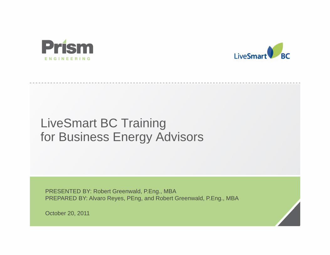
A dit O iAudit Overview1. Carry out billing analysis before going on
itsite2. Understand the current end uses through
it dit d d t th ion site audit and data gathering3. Calculate the existing energy use for
i ifi t f tisignificant areas of consumption4. Identify which opportunities apply and
estimated cost and savings, including incentives
5. Put together an appropriate “package” that meets financial expectations
5

D l fil f billDevelop energy profiles from bills• ie Base gas vs. weather dependent
Building "A"Gas Space Heat & Gas Domestic Hot Water, Electric A/C
12,00014,00016,000
Wh
Building "B"Electric Space Heat, Electric A/C, Gas Domestic Hot Water
12 00014,00016,00018,000
Wh
02,0004,0006,0008,000
10,000
Jan Feb Mar Apr May June July Aug Sept Oct Nov Dec
Equi
vale
nt k
W
02,0004,0006,0008,000
10,00012,000
Jan Feb Mar Apr May June July Aug Sept Oct Nov Dec
Equi
vale
nt k
W
Monthly Electricity Consumption Monthly Gas Consumption Monthly Electricity Consumption Monthly Gas Consumption
Building "C"Gas Space Heat & Domestic Hot Water, no A/C
10 000
12,000
Building "D"Gas Space Heat & Process Heat, 2 Week August Shutdown
10 000
12,000
0
2,000
4,000
6,000
8,000
10,000
Equi
vale
nt k
Wh
0
2,000
4,000
6,000
8,000
10,000
Equi
vale
nt k
Wh
6
0Jan Feb Mar Apr May June July Aug Sept Oct Nov Dec
Monthly Electricity Consumption Monthly Gas Consumption
0Jan Feb Mar Apr May June July Aug Sept Oct Nov Dec
Monthly Electricity Consumption Monthly Gas Consumption
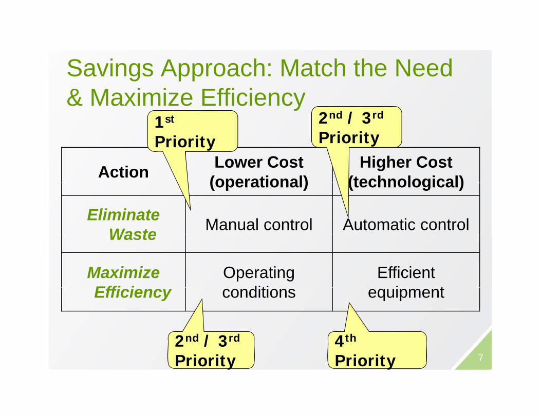
Savings Approach: Match the Need g pp& Maximize Efficiency
1st 2nd / 3rd
Action Lower Cost(operational)
Higher Cost(technological)
Priority Priority
(operational) (technological)
Eliminate Waste Manual control Automatic controlWaste
Maximize Effi i
Operatingditi
Efficienti tEfficiency conditions equipment
4th2nd / 3rd
74th
Priority2nd / 3rd
Priority

Example: Match the Need HVAC pControl
S tb k/S t• Setback/Setup• Start/Stop• Outside Air Reset• Ventilation on Demand
8
E l M i i Effi iExample: Maximize Efficiency
• Proper Maintenance• High Efficiency Motors• High Efficiency Motors• Energy Star Equipment
9
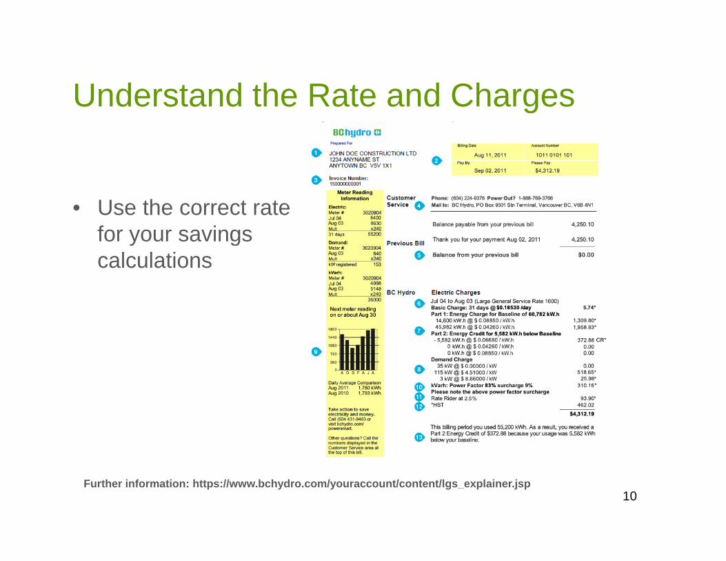
Understand the Rate and ChargesUnderstand the Rate and Charges
• Use the correct rate for your savings y gcalculations
10Further information: https://www.bchydro.com/youraccount/content/lgs_explainer.jsp

QUANTIFYING ENERGYQUANTIFYING ENERGY CONSUMPTION AND COSTS

S Q ti f BEA’Some Questions from BEA’sQ1: “Hydro gives $35 to $50 to change to ECM fan Q y g $ $ gmotors, is this sufficient to show a good ROI on this change?”
Q2: “I would also like to discuss water heaters and boiler systems to understand better when they do make business sense to have them upgraded i e if the boilerbusiness sense to have them upgraded, i.e. if the boiler is old then the business case looks like …”
• There is no “one size fits all” answerThere is no one size fits all answer• To properly address these questions you need to
understand how to quantify the existing energy ti f i f i tconsumption of any piece of equipment
12
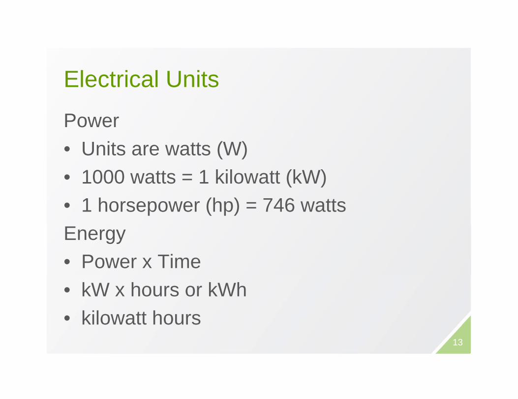
El t i l U itElectrical Units
PowerPower• Units are watts (W)• 1000 watts = 1 kilowatt (kW)• 1000 watts = 1 kilowatt (kW)• 1 horsepower (hp) = 746 wattsEnergy• Power x Time• kW x hours or kWh• kilowatt hours
13

Thermal UnitsThermal UnitsEnergy• Unit of thermal energy is a joule (J)
Typically use MJ or GJ• 1 kWh = 3.6 MJ = 0.0036 GJ• 1 kWh = 3413 BTUPower• 1 joule per second = 1 watt1 joule per second 1 watt• 1 ton of refrigeration
= 12 000 BTU/h 12 000 BTU/h= 3.52 kW 14

Power vs. Energy Summarygy yHow ______ $ How ______ $Fast Much
How Fast x HowH Big H Many LongDemand Consumption
How Fast x How _____How Big x How _____Many Long(Peak) When
Kilowatt hoursXKilowattsPower Energy
When
kW kWhkVA
= Power Factor
1 HP = 746 WattsKilovoltamps
J, kJ, MJ, GJBTU
, , ,BTU/hr
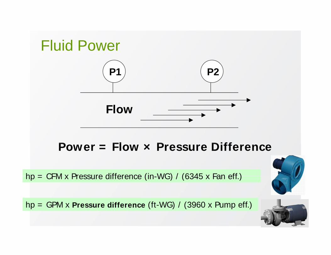
Fluid PowerFluid PowerP1 P2
FlowFlow
P Fl × P DiffPower = Flow × Pressure Difference
hp = CFM x Pressure difference (in WG) / (6345 x Fan eff )hp = CFM x Pressure difference (in-WG) / (6345 x Fan eff.)
hp = GPM x Pressure difference (ft-WG) / (3960 x Pump eff.)
16
p ( ) / ( p )
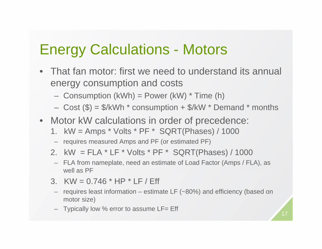
E C l l ti M tEnergy Calculations - Motors• That fan motor: first we need to understand its annual
energy consumption and costs– Consumption (kWh) = Power (kW) * Time (h)– Cost ($) = $/kWh * consumption + $/kW * Demand * monthsCost ($) $/kWh consumption + $/kW Demand months
• Motor kW calculations in order of precedence: 1. kW = Amps * Volts * PF * SQRT(Phases) / 1000
req ires meas red Amps and PF (or estimated PF)– requires measured Amps and PF (or estimated PF)
2. kW = FLA * LF * Volts * PF * SQRT(Phases) / 1000 – FLA from nameplate, need an estimate of Load Factor (Amps / FLA), as
well as PFwell as PF
3. KW = 0.746 * HP * LF / Eff– requires least information – estimate LF (~80%) and efficiency (based on
motor size)– Typically low % error to assume LF= Eff
17
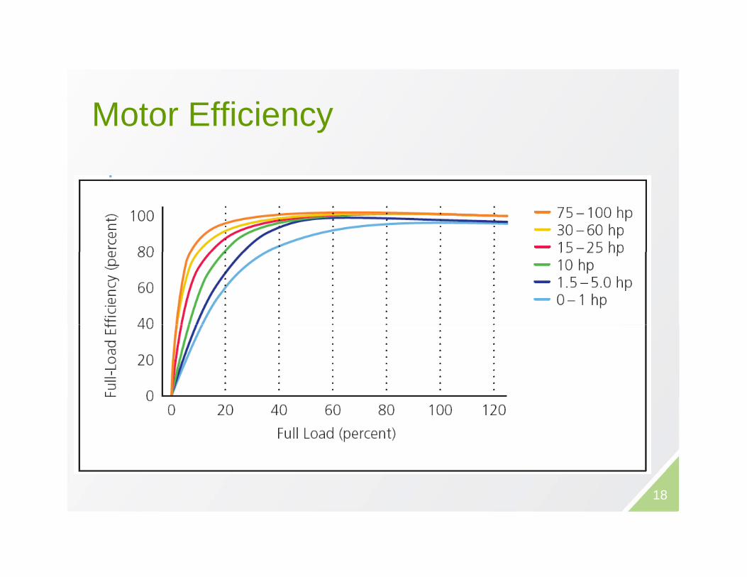
M t Effi iMotor Efficiency
18
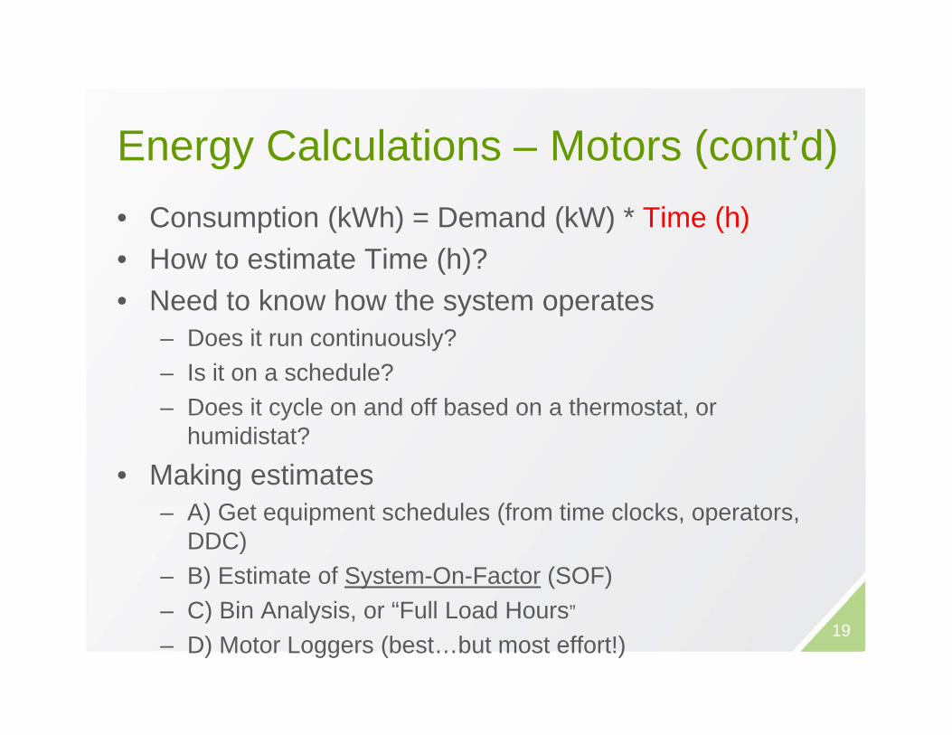
E C l l ti M t ( t’d)Energy Calculations – Motors (cont’d)• Consumption (kWh) = Demand (kW) * Time (h)p ( ) ( ) ( )• How to estimate Time (h)? • Need to know how the system operates
– Does it run continuously?– Is it on a schedule?– Does it cycle on and off based on a thermostat, orDoes it cycle on and off based on a thermostat, or
humidistat?
• Making estimatesA) G t i t h d l (f ti l k t– A) Get equipment schedules (from time clocks, operators, DDC)
– B) Estimate of System-On-Factor (SOF)– C) Bin Analysis, or “Full Load Hours”
– D) Motor Loggers (best…but most effort!)19
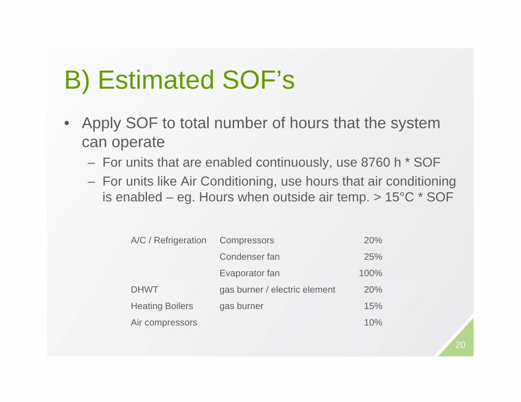
B) E ti t d SOF’B) Estimated SOF’s• Apply SOF to total number of hours that the systemApply SOF to total number of hours that the system
can operate– For units that are enabled continuously, use 8760 h * SOF– For units like Air Conditioning, use hours that air conditioning
is enabled – eg. Hours when outside air temp. > 15°C * SOF
A/C / Refrigeration Compressors 20%
Condenser fan 25%
Evaporator fan 100%p
DHWT gas burner / electric element 20%
Heating Boilers gas burner 15%
Air compressors 10%
20

C) Bi A l iWeather Database Query Output
Location: Vancouver Intl A
C) Bin AnalysisFor equipment like heating
Start/End Dates: 1/1/2010 12/31/2010
Days of Week: ALL
Including/Excluding: ALL
From/To: ALL ALL
Period Days/Hrs: 365 8760For equipment like heating boilers, run hours are related to outside air t t
y /
Search Type: Partition
Option: Range from ‐10 to 16, Interval 2
Partition Hours Avg. OAT oC SOF[ 10 0 8 0 ] 4 8 6 80%temperature
– A boiler will run more hours on the coldest day, and close to zero at the balance point
[ ‐10.0 , ‐8.0 ] 4 ‐8.6 80%[ ‐8.0 , ‐6.0 ] 16 ‐6.8 74%[ ‐6.0 , ‐4.0 ] 30 ‐5.0 68%[ ‐4.0 , ‐2.0 ] 67 ‐3.1 62%[ ‐2.0 , 0.0 ] 58 ‐0.8 55%[ ]to zero at the balance point
– Caution if equipment is severely over/under sized
– Also need to factor in whether
[ 0.0 , 2.0 ] 166 1.1 49%[ 2.0 , 4.0 ] 390 3.1 43%[ 4.0 , 6.0 ] 782 5.1 37%[ 6.0 , 8.0 ] 1272 7.0 31%[ 8.0 , 10.0 ] 1311 8.9 25%Also need to factor in whether
or not there is setback / set up – SOF will be lower during those hrs
[ 10.0 , 12.0 ] 1040 11.0 18%[ 12.0 , 14.0 ] 1032 12.9 12%[ 14.0 , 16.0 ] 963 14.9 6%
>= 16 1629 19.0 0%
21Hours < 16oC 7131Mean SOF 24%
Full Load Hours 1740
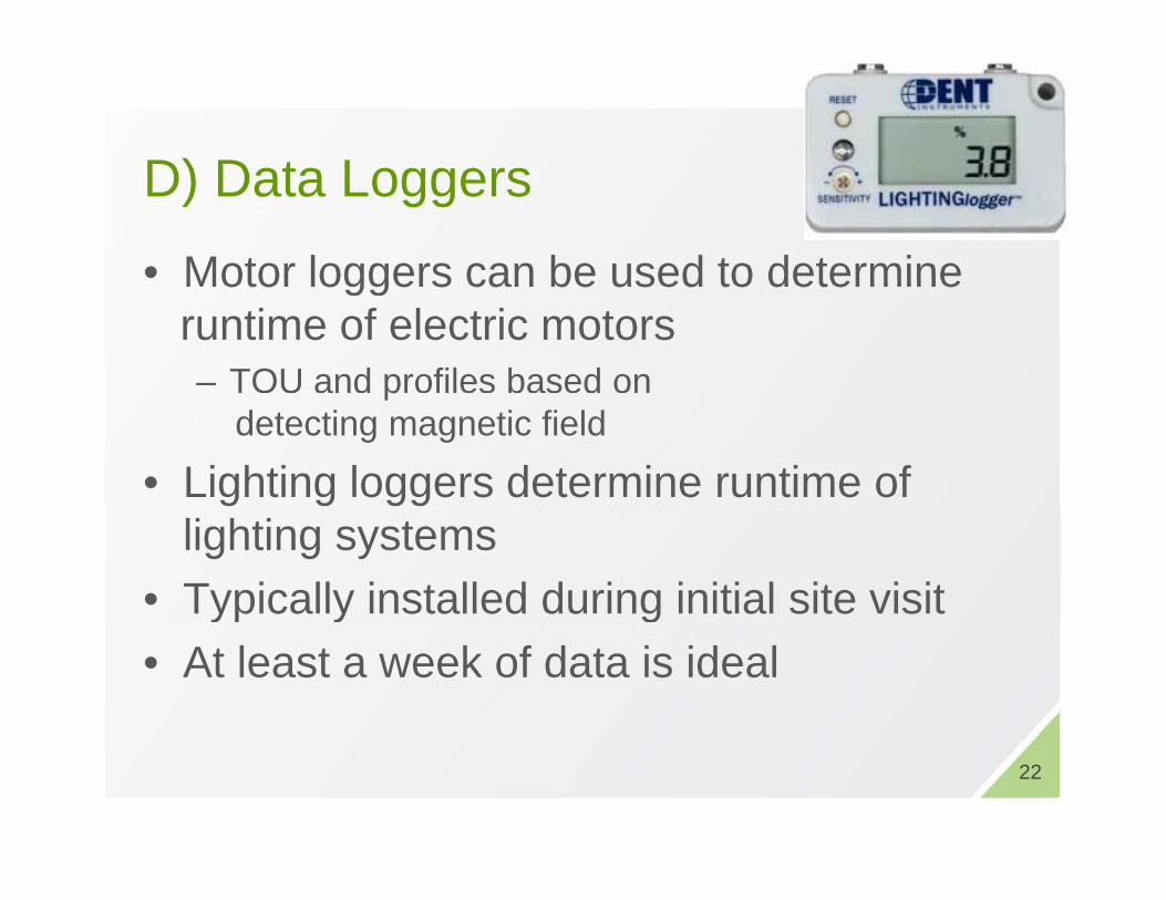
D) D t LD) Data Loggers
• Motor loggers can be used to determineMotor loggers can be used to determine runtime of electric motors– TOU and profiles based on p
detecting magnetic field
• Lighting loggers determine runtime of lighting systems
• Typically installed during initial site visityp y g• At least a week of data is ideal
22

Logger Data Outputgg p
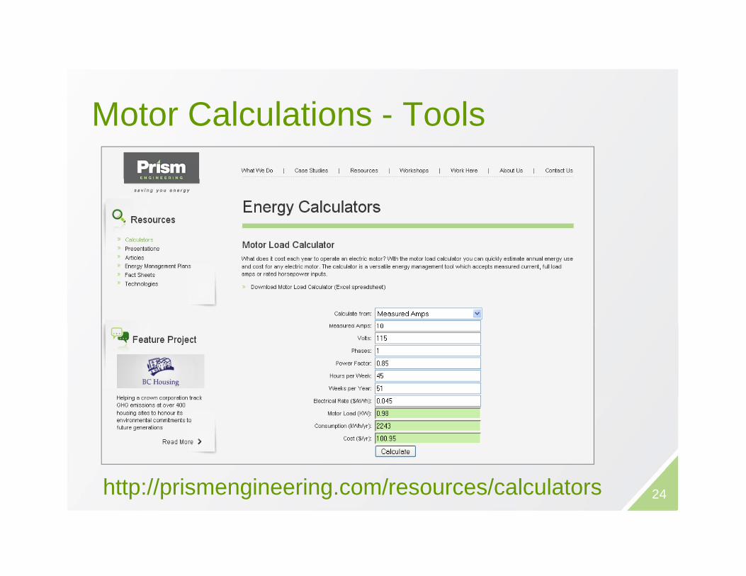
M t C l l ti T lMotor Calculations - Tools
http://prismengineering.com/resources/calculators 24

E C l l ti Th lEnergy Calculations - Thermal
BTU = Rate (BTU/h) * hours
BTU = 500 * GPM * delta T (°F) * hours for waterBTU = 500 GPM delta T ( F) hours for water
BTU = 1.08 * CFM * delta T (°F) * hours for air
Looks easy, but how do we figure out flows, temperatures, & time?Apologies for the Imperial Units!
25
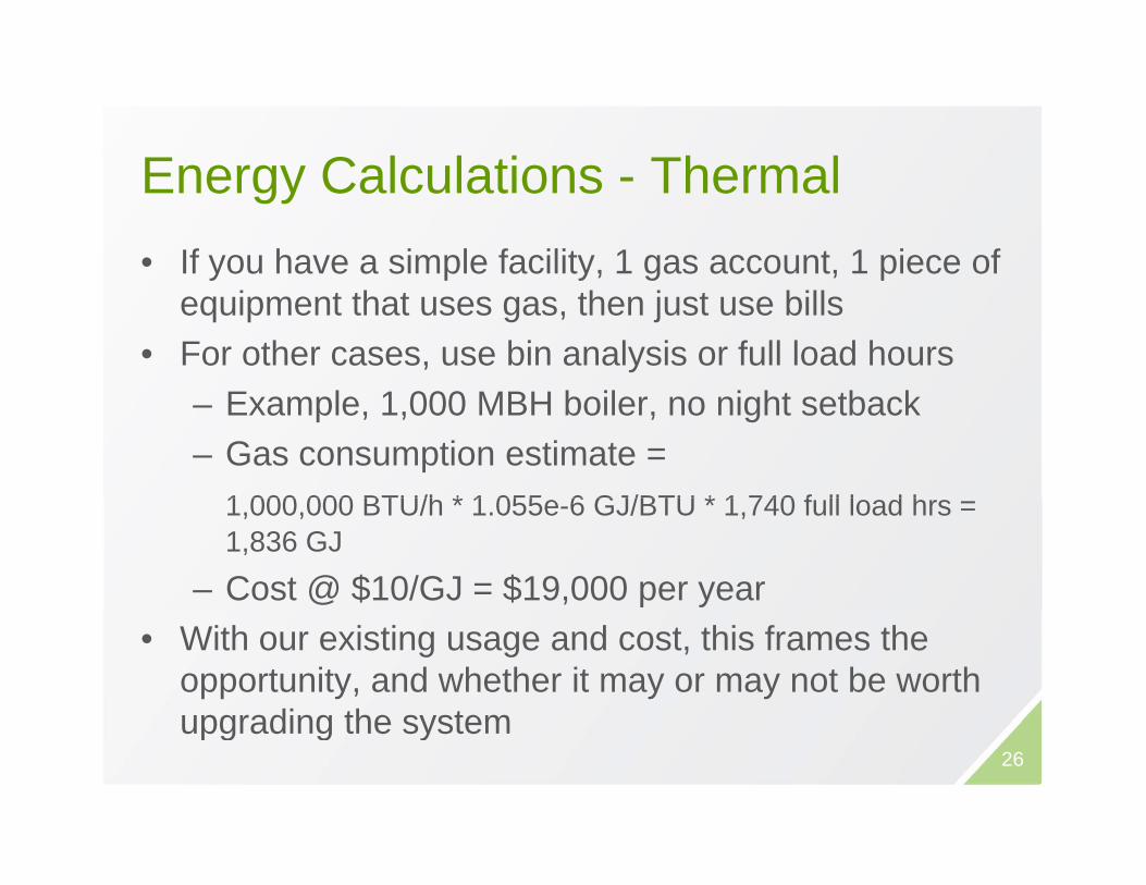
E C l l ti Th lEnergy Calculations - Thermal• If you have a simple facility, 1 gas account, 1 piece of y p y, g , p
equipment that uses gas, then just use bills• For other cases, use bin analysis or full load hours
– Example, 1,000 MBH boiler, no night setback– Gas consumption estimate =
1 000 000 BTU/h * 1 055 6 GJ/BTU * 1 740 f ll l d h1,000,000 BTU/h * 1.055e-6 GJ/BTU * 1,740 full load hrs = 1,836 GJ
– Cost @ $10/GJ = $19,000 per year • With our existing usage and cost, this frames the
opportunity, and whether it may or may not be worth upgrading the systemupgrading the system
26

Ventilation Energy Rate gyCalculations• In fan systems, there is an energy penalty in bringing y , gy p y g g
in outside air, which may need to be heated or cooled– Energy Use dependent on air flow (CFM), %outside air,
OAT and supply air temperatureOAT, and supply air temperature
27
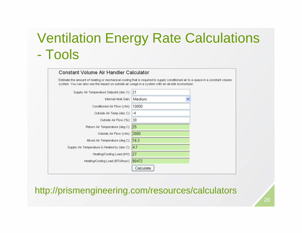
Ventilation Energy Rate Calculations gy- Tools
http://prismengineering com/resources/calculators28
http://prismengineering.com/resources/calculators

Example:Heating Outside Air
• 100,000 ft2 Office Building in Vancouver• Total air supply 1 cfm/ft2 pr 100,000 cfm• Outside air at 20% or 20,000 cfm (1000
people at 20 cfm/person) • 2.12 cfm per L/s so there are 9434 L/s• Based on HDD of 2800 C for Vancouver
(10 year average)• Thermal balance point in the building is
18C18C• 7 day operation, 6 am to 6 pm
29
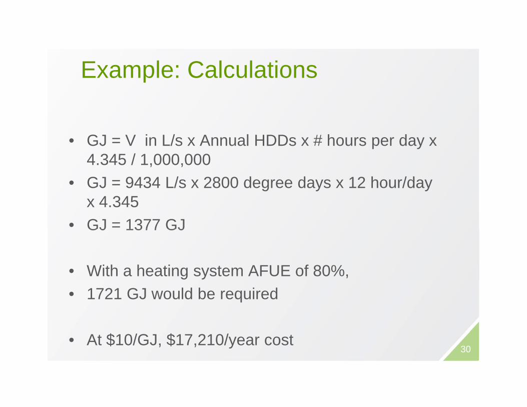
Example: CalculationsExample: Calculations
• GJ = V in L/s x Annual HDDs x # hours per day x 4.345 / 1,000,000GJ 9434 L/ 2800 d d 12 h /d• GJ = 9434 L/s x 2800 degree days x 12 hour/day x 4.345
• GJ = 1377 GJGJ 1377 GJ
• With a heating system AFUE of 80%, • 1721 GJ would be required
• At $10/GJ, $17,210/year cost 30

Ventilation Energy Calculations - Tools
http://prismengineering com/resources/calculatorshttp://prismengineering.com/resources/calculators31
HVAC SYSTEMS- HVAC Controls/ Economizers- Demand Control Ventilation- Variable Speed Drives

Ti Cl kTime Clocks• Simple time controls, p ,
common in small buildings to turn equipment on/offM h i l ti l k• Mechanical time clocks– Have “dogs” which establish the on
and off times – do they exist?7 d h i l ti l k– 7 day mechanical time clocks available
• Digital time clocks– Some additional functionality (365
day programming)– Astronomical time programs for
exterior lighting controlexterior lighting control33
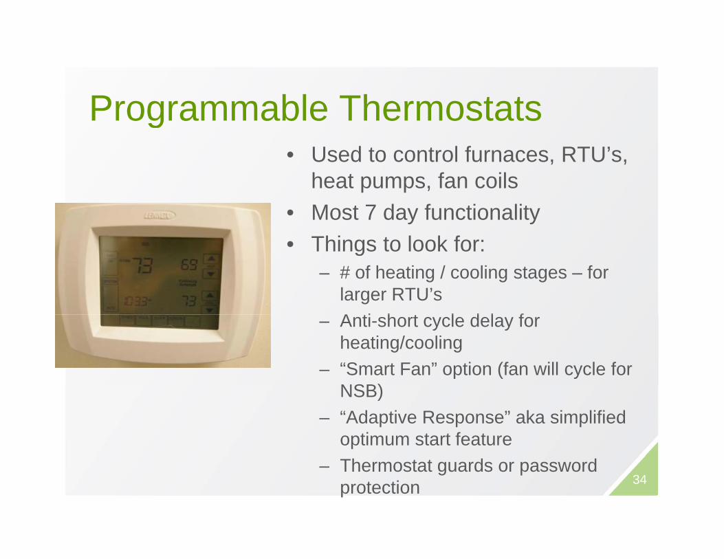
Programmable ThermostatsProgrammable Thermostats• Used to control furnaces, RTU’s,
h t f ilheat pumps, fan coils• Most 7 day functionality• Things to look for:• Things to look for:
– # of heating / cooling stages – for larger RTU’sA ti h t l d l f– Anti-short cycle delay for heating/cooling
– “Smart Fan” option (fan will cycle for NSB)NSB)
– “Adaptive Response” aka simplified optimum start feature
– Thermostat guards or password protection 34

35

Occupancy Sensors for HVACOccupancy Sensors for HVAC• Install occupancy sensors for HVAC equipment
in areas with variable but not constant occupancy• Requirements:
If DDC t l d i t t ll d t– If DDC system already exists, controllers need to have spare inputs
– If no DDC system, need to replace thermostat with o C sys e , eed o ep ace e os aone having aux. input, or integrated occ. sensor
• Considerations:– Does the sensor cover the space adequately?– Is the unoccupied temperature too high or low,
resulting in long recovery time when occupancy isresulting in long recovery time when occupancy is sensed? 36

H t l G t R C t lHotel Guest Room Controls• INNCOM system
– Thermostat with occupancy sensor and door switch detect occupancy
– Room is put into setback / setup mode during unoccupied periods
– Master controller puts rooms that are not booked into a broader setback / setup
d ( ith ti )mode (with reservations)– Fan, heating, and cooling
energy savings

BC Hydro PIP Incentives OccupancyBC Hydro PIP Incentives - Occupancy
38

S tb k S tti d FiltSetback Setting and Filters
• Night temperature setback/up – Heating: -1°C = 3% of heating bill
C li +1°C 1% f li bill– Cooling: +1°C = 1% of cooling bill
• Maintain air filters• Maintain air filters– Dirty filter + 25 000 cfm = 5 kW fan
energy!gy– Plus energy to cool!
39
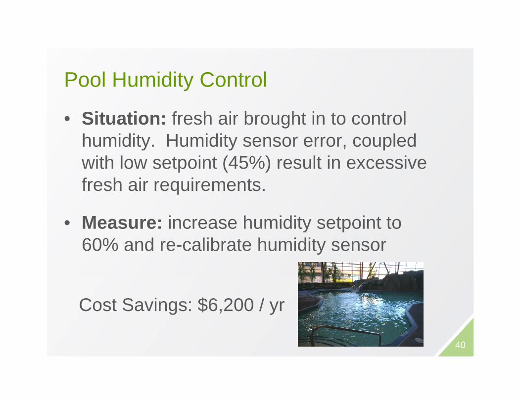
P l H idit C t lPool Humidity Control
• Situation: fresh air brought in to control ghumidity. Humidity sensor error, coupled with low setpoint (45%) result in excessive fresh air requirements.
• Measure: increase humidity setpoint toMeasure: increase humidity setpoint to 60% and re-calibrate humidity sensor
Cost Savings: $6,200 / yr
40
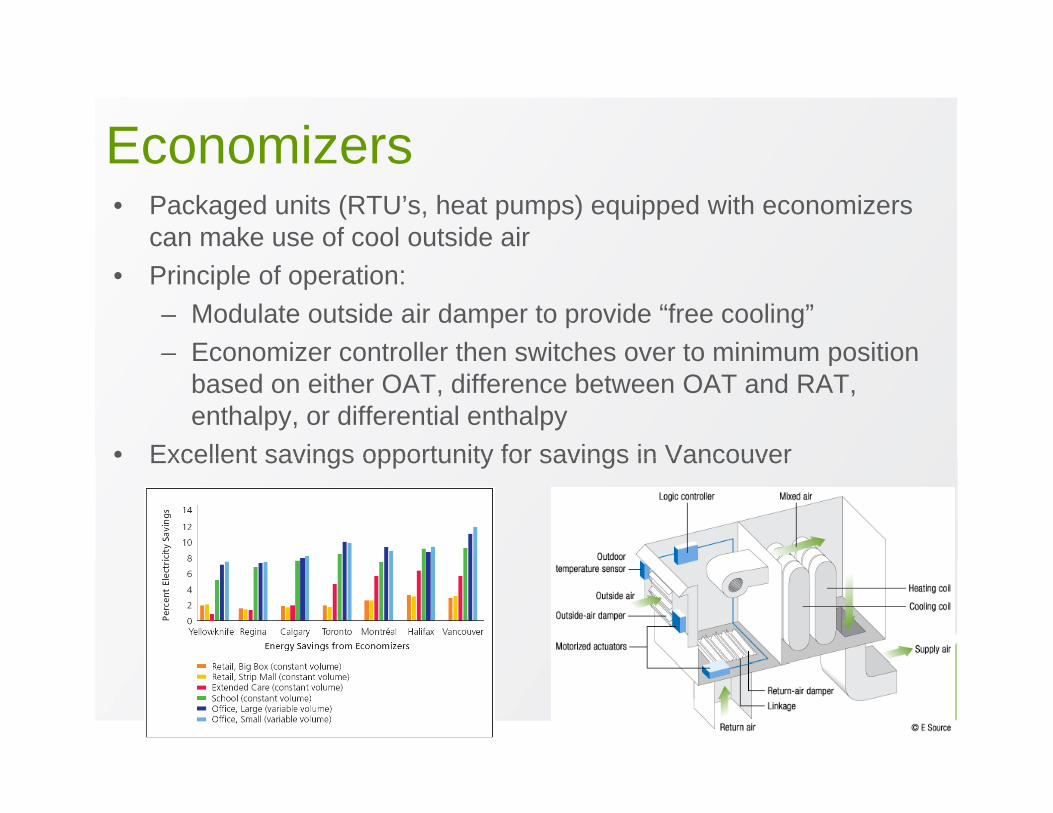
EconomizersEconomizers• Packaged units (RTU’s, heat pumps) equipped with economizers
can make use of cool outside air• Principle of operation:
– Modulate outside air damper to provide “free cooling”– Economizer controller then switches over to minimum positionEconomizer controller then switches over to minimum position
based on either OAT, difference between OAT and RAT, enthalpy, or differential enthalpy
• Excellent savings opportunity for savings in VancouverExcellent savings opportunity for savings in Vancouver
41

EconomizersEconomizersOutside Air Intake
R li f AiRelief Air Damper
E i C t ll t d A t t
Enthalpy Sensor
Economizer Controller mounted on Actuator
42
E i F ilEconomizer Failure• Packaged RTU economizers fail often because of
– Broken linkages– Actuator failure– Faulty outside air temperature or enthalpy sensor
• Energy impact of a failed economizer:– Outside air damper stuck open: increased heating energy– Outside air damper stuck closed: increased mechanical cooling energy, plus
poor IAQpoor IAQ
• Ways to troubleshoot economizer operation:– On a cold day (<10°C OAT) when damper is mostly closed, force unit into
cooling mode (reduce Temperature setpoint). Observe if damper opens up g ( p p ) p p pfor free cooling, or if mechanical cooling comes on.
– On a cool day when damper is open, either heat the OAT sensor (with your hand or a hair dryer), or spray water on the enthalpy sensor. Damper should close to minimum if functioning properlyshould close to minimum, if functioning properly.
43
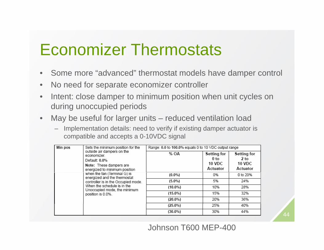
E i Th t tEconomizer Thermostats• Some more “advanced” thermostat models have damper control• No need for separate economizer controller• Intent: close damper to minimum position when unit cycles on
during unoccupied periodsg p p• May be useful for larger units – reduced ventilation load
– Implementation details: need to verify if existing damper actuator is compatible and accepts a 0-10VDC signal
44
Johnson T600 MEP-400

Fact SheetFact Sheet
45
http://prismengineering.com/resources/fact_sheets
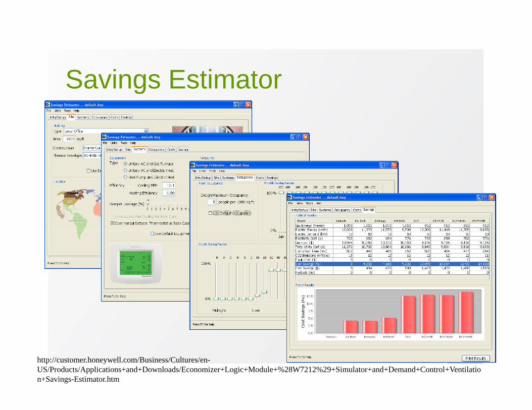
Savings EstimatorSavings Estimator
46http://customer.honeywell.com/Business/Cultures/en-US/Products/Applications+and+Downloads/Economizer+Logic+Module+%28W7212%29+Simulator+and+Demand+Control+Ventilation+Savings-Estimator.htm

BC Hydro PIP Incentives EconBC Hydro PIP Incentives -Econ
47

HVAC SYSTEMS- HVAC Controls/ Economizers- Demand Control Ventilation- Variable Speed Drives

M Q ti f BEA’More Questions from BEA’sQ3: Explain how CO2 sensors can be installed to Q p
reduce energy? Cost associated etc.
49

V til ti /E h tVentilation/Exhaust• Double Cost
– Cost of air movement (fans)– Cost of make-up heating
• Shut down ventilation/exhaust systems.• Use correct ventilation/exhaust rates.
B l i fl f i t• Balance air flows for appropriate pressure.• Zone ventilated areas and sequence air flow
based on contaminant levelsbased on contaminant levels.
50

D d C t l V til tiDemand Control Ventilation • Air handling systems are designed to provide g y g p
adequate fresh air to meet code and guidelines (ASHRAE 62.1)Mi i d i h ld b ffi i• Minimum damper setting should be sufficient to provide these ventilation requirements
• Install CO2 transmitters and provide feedback• Install CO2 transmitters and provide feedback to modulate outside air damper
• Under periods of low occupancy, reduce U de pe ods o o occupa cy, educeoutside air rate
• Works best for spaces with variable ( )
51occupancy (gymnasiums, auditoriums, etc.)
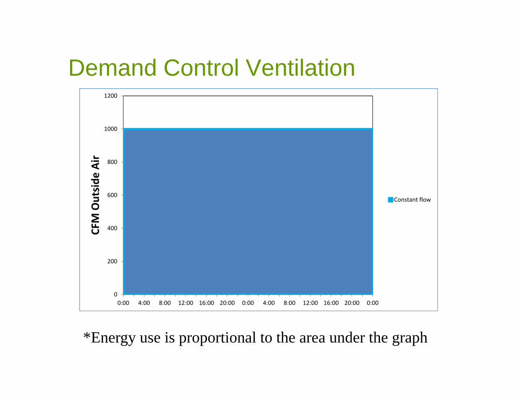
Demand Control VentilationDemand Control Ventilation1200
800
1000
e Air
600
FM Outside
Constant flow
200
400CF
00:00 4:00 8:00 12:00 16:00 20:00 0:00 4:00 8:00 12:00 16:00 20:00 0:00
*Energy use is proportional to the area under the graph
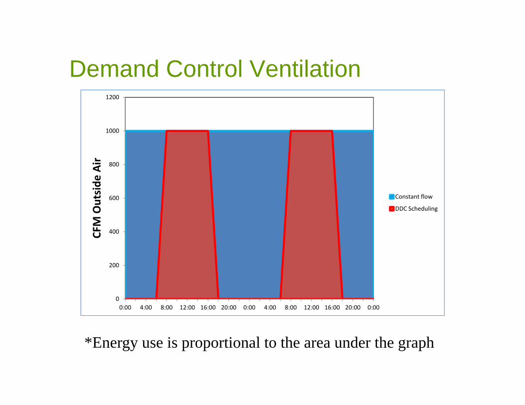
Demand Control Ventilation1200
Demand Control Ventilation
800
1000
e Air
600
FM Outside
Constant flow
DDC Scheduling
200
400CF
00:00 4:00 8:00 12:00 16:00 20:00 0:00 4:00 8:00 12:00 16:00 20:00 0:00
*Energy use is proportional to the area under the graph
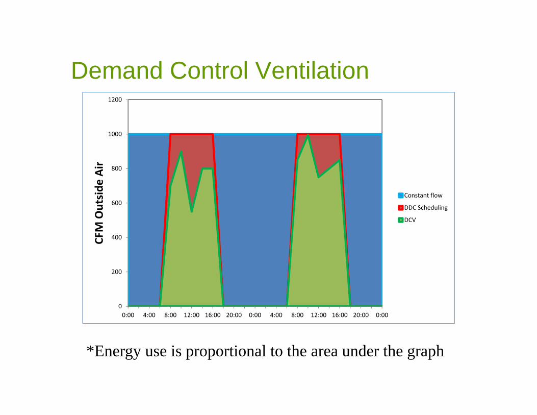
Demand Control Ventilation1200
Demand Control Ventilation
800
1000
e Air
600
FM Outside
Constant flow
DDC Scheduling
DCV
200
400CF
00:00 4:00 8:00 12:00 16:00 20:00 0:00 4:00 8:00 12:00 16:00 20:00 0:00
*Energy use is proportional to the area under the graph

CO2 T itt L tiCO2 Transmitter Location• Return Air Duct / Plenum
– Takes a ‘blended average’ space CO2 concentration
– Appropriate for small spaces or low diversity
S• Space– May put one transmitter in zone of greatest
occupancyoccupancy
55

DCV on Factory Economizer yController
56

Case Study: Banquet/Conference y qHall AHU Control Optimization
• Situation: Air handling systems have demand control ventilation, but CO2 sensor
d 2 000 ti l lti ireads 2,000 ppm continuously, resulting in 100% fresh air brought in and heated/cooled. Schedules also found to be excessively longSchedules also found to be excessively long.
• Measure: Re-calibrate CO2 sensor and trim operating hoursoperating hours.
Cost Savings: $3,600 / yr57

S R h C tSome Rough Costs
Base Case: 7.5 ton RTU, gas heating, DX Cooling
Installed Cost
Programmable thermostat $500$500Web‐based programmable thermostat $1,000
Add Economizer, simple controller $3,000
DCV on simple controller, additional $1,000p , $ ,
DDC ‐ Economizer, web interface $8,000‐$12,000
DCV on DDC controller, additional $1,000
Apply cost data with caution!58
Apply cost data with caution!
HVAC SYSTEMS- HVAC Controls/ Economizers- Demand Control Ventilation- Variable Speed Drives
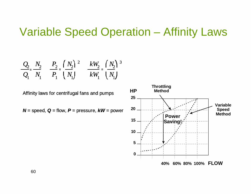
Variable Speed Operation – Affinity Lawsp p y
Q2
Q1
N2
N1
P2
P1
N2
N1
2 kW2
kW1
N2
N1
3
= = =Q2
Q1
N2
N1
P2
P1
N2
N1
2 kW2
kW1
N2
N1
3
= = =
Affinity laws for centrifugal fans and pumps
N d Q fl P kW
Affinity laws for centrifugal fans and pumps
N d Q fl P kW 20
25
VariableSpeed
ThrottlingMethod HP
N = speed, Q = flow, P = pressure, kW = powerN = speed, Q = flow, P = pressure, kW = power 20
15
10
SpeedMethodPower
Saving!
0
5
60
40% 60% 80% 100% FLOW
Variable Speed Good ApplicationsVariable Speed - Good Applications
• Replace outlet dampers or inlet guide vanes on variable air volume systems
• Reduce fan speed of constant air volume systems during periods of low occupancyduring periods of low occupancy
• Eliminate throttling • i.e. pump with discharge valve throttled
• Eliminate single speed fan / pump cycling, and run continuously at a lower speed• Cooling tower fans• Cooling tower fans• Ice Rink brine pumps
61

Variable Speed Bad ApplicationsVariable Speed - Bad Applications
• Fan systems with DX cooling• Reduced fan speed may end up in excessively low
discharge air temperature & coil freezing
• Systems with limitations on pressureSyste s t tat o s o p essu e• Open circuit pumping systems – need to achieve a certain
system head, and lower speed may not achieve it
• Limited turn down on fan / pump capacity• Limited turn-down on fan / pump capacity• If system is under-sized or working hard, then the speed
may never be reduced, and no savings may ever be hi d!achieved!
62
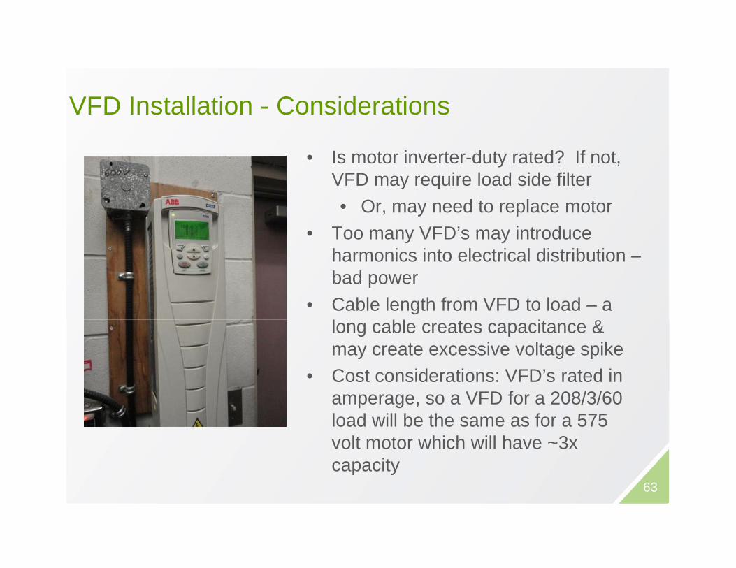
VFD Installation ConsiderationsVFD Installation - Considerations
• Is motor inverter-duty rated? If not, VFD may require load side filterVFD may require load side filter• Or, may need to replace motor
• Too many VFD’s may introduce h i i l i l di ib iharmonics into electrical distribution –bad power
• Cable length from VFD to load – a l bl t it &long cable creates capacitance & may create excessive voltage spike
• Cost considerations: VFD’s rated in VFD f 208/3/60amperage, so a VFD for a 208/3/60
load will be the same as for a 575 volt motor which will have ~3x capacitycapacity
63
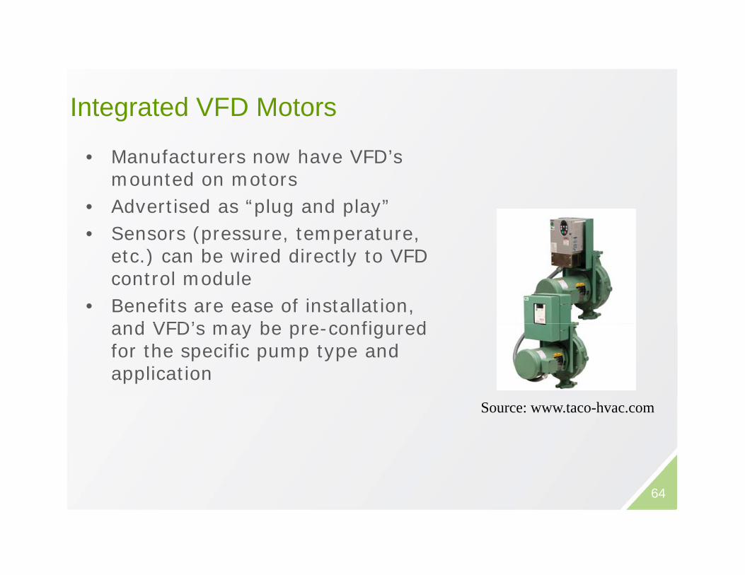
Integrated VFD MotorsIntegrated VFD Motors
• Manufacturers now have VFD’s mounted on motorsmounted on motors
• Advertised as “plug and play”• Sensors (pressure, temperature,
t ) b i d di tl t VFD etc.) can be wired directly to VFD control module
• Benefits are ease of installation, d VFD’ b fi d and VFD’s may be pre-configured
for the specific pump type and application
Source: www.taco-hvac.com
64
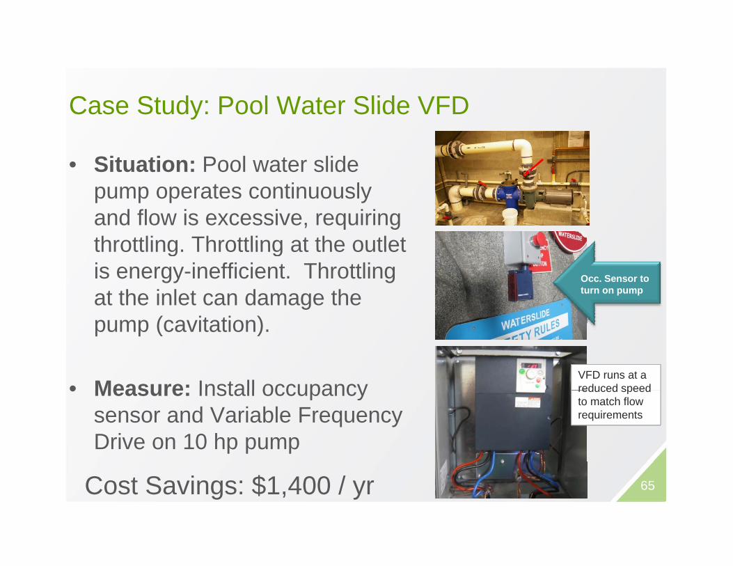
Case Study: Pool Water Slide VFDCase Study: Pool Water Slide VFD
• Situation: Pool water slide pump operates continuously and flow is excessive, requiring throttling Throttling at the outletthrottling. Throttling at the outlet is energy-inefficient. Throttling at the inlet can damage the
( it ti )
Occ. Sensor to turn on pump
pump (cavitation).
• Measure: Install occupancyVFD runs at a reduced speed• Measure: Install occupancy
sensor and Variable Frequency Drive on 10 hp pump
reduced speed to match flow requirements
Cost Savings: $1,400 / yr 65
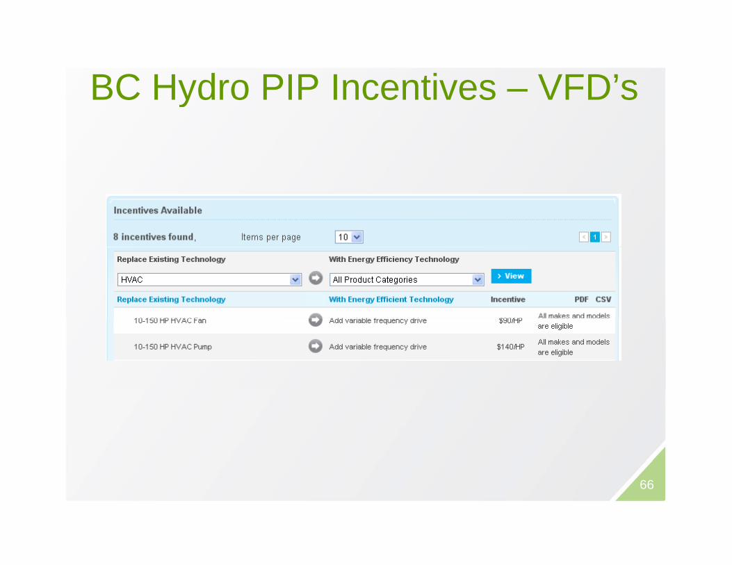
BC Hydro PIP Incentives – VFD’sy
66
Kitchen Hood Demand Control VentilationKitchen Hood Demand Control Ventilation
• Packaged systems including the following:• VFD installation on make-up air fan & exhaust fan
motor• Hood temperature sensors and/or optical smoke
detectors
• Exhaust fan speed is determined by cooking activity taking placeactivity taking place
• MAU speed tracks Exhaust fan speed• For systems with transfer air fans, outside air y
damper of main ventilation fan tracks Exhaust• Cost: $20-30k for a system with 10 hp
supply/exhaust fanssupply/exhaust fans67

68

ApplicationsApplications
• Variable cooking schedule • Constant cooking scheduleGood Bad
g• i.e. Prep periods with low
activity
• Simple system with 1
g• i.e. Busy kitchen – limited
savings
• Complex system with• Simple system with 1 MAU supplying the kitchen directly
• Complex system with transfer air fan(s) – need to maintain –ve pressure in
• Indirect gas-fired MAU• Direct gas-fired MAU w/
modulating gas burner
kitchen• Direct gas-fired MAU w/ 1 or
2 stage gas burnermodulating gas burner 2 stage gas burner• Cannot reduce speed or it
may result in excessively high CO concentrations enteringCO concentrations entering kitchen 69
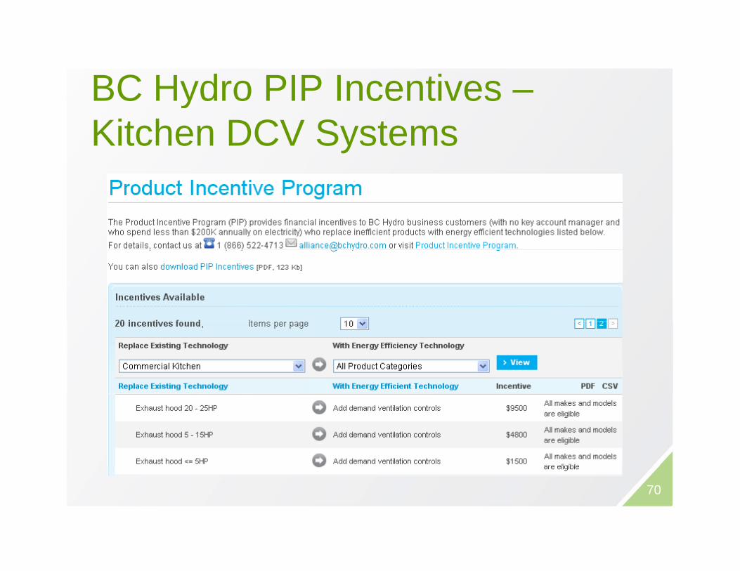
BC Hydro PIP Incentives –yKitchen DCV Systems
70

THERMALTHERMAL

Atmospheric Boilersp
• Aka “Natural Draft” boilersAka Natural Draft boilers• Air is drawn through the boiler,
assisted by the draft hoodTh l ffi i t i ll 80%• Thermal efficiency typically 80% (maximum theoretical eff)
• Seasonal efficiency lower due to:• Radiative (jacket) losses• Draft hood continues to draw air
through boiler cooling it downthrough boiler, cooling it down• Typical seasonal efficiency 65-75%
72
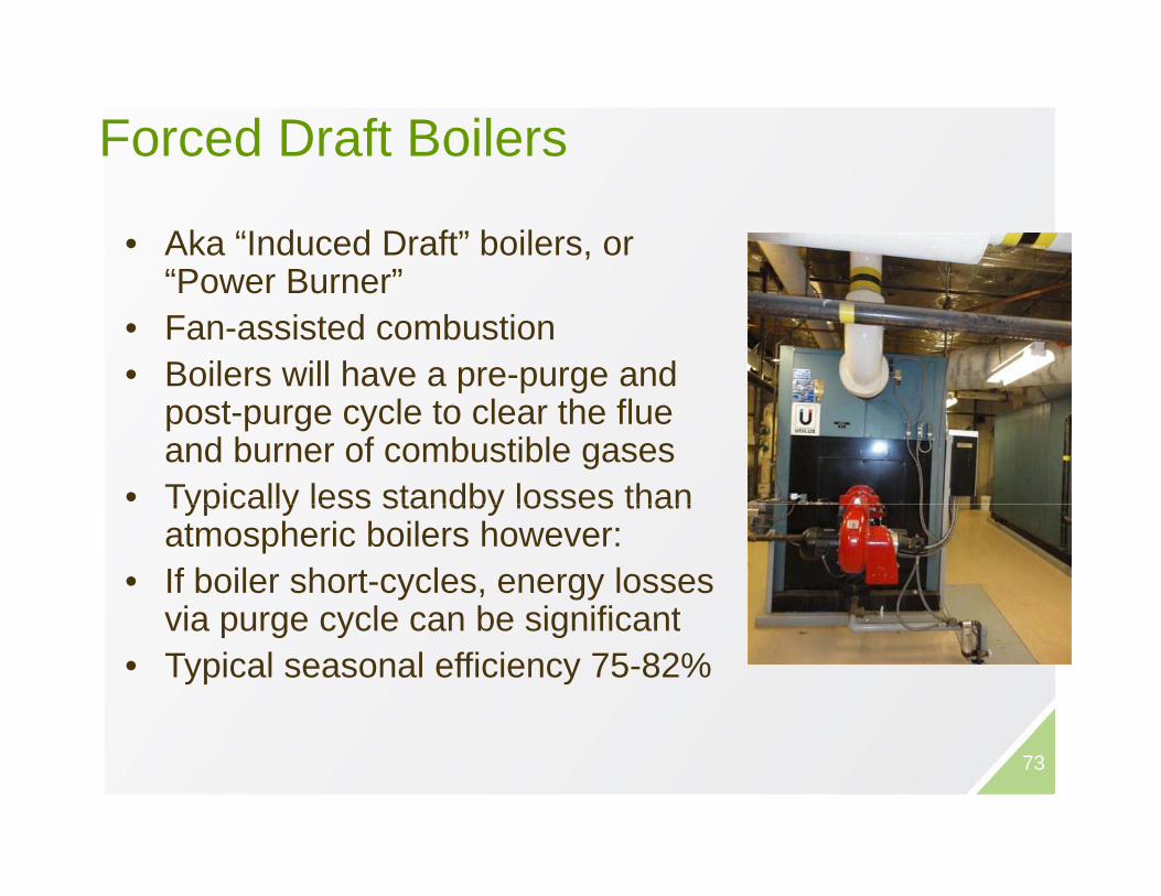
Forced Draft Boilers
• Aka “Induced Draft” boilers, or “Power Burner”Power Burner
• Fan-assisted combustion• Boilers will have a pre-purge and p p g
post-purge cycle to clear the flue and burner of combustible gases
• Typically less standby losses thanTypically less standby losses than atmospheric boilers however:
• If boiler short-cycles, energy losses via purge cycle can be significantvia purge cycle can be significant
• Typical seasonal efficiency 75-82%
73

Condensing Boilersg
• Similar burner to Forced DraftR i l t t• Requires low return water temperature to achieve high efficiencies
• Low return water temperature (<50oC) allows for flue gases to condense
• Heat exchanger constructed of high-grade materials to allow for condensation of flue gasescondensation of flue gases
• Seasonal efficiency > 86%
74

B il Pl t O t itiBoiler Plant Opportunities
Boiler Controllers• Boiler Controllers– Sequence boilers & circulators– Boiler supply temperature resetpp y p– Warm weather shutdown
• Install combustion controllersA t ti ll dj t f l i f– Automatically adjust fuel-air for forced draft burners
• Reduce standby losses: flue d i l i ldampers or isolation valves
• Boiler replacement – mid-efficiency (near condensing) or high-efficiency ( g) g y(condensing) 75
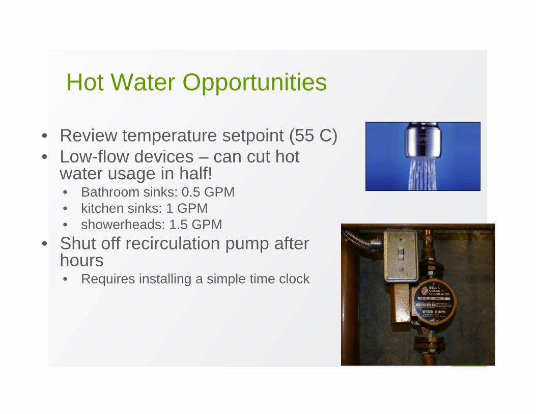
H t W t O t itiHot Water Opportunities
R i i ( C)• Review temperature setpoint (55 C)• Low-flow devices – can cut hot
water usage in half!g• Bathroom sinks: 0.5 GPM • kitchen sinks: 1 GPM• showerheads: 1.5 GPM
• Shut off recirculation pump after hours• Requires installing a simple time clockq g p

S R h S i FiSome Rough Savings Figures• Caution: a detailed analysis of the application y pp
seasonal efficiency is required for accurate estimation of savings
At B il F d D ft 10 20% i– Atm. Boiler Forced Draft 10-20% savings– Atm. Boiler Condensing 20-30% savings– Add Vent Damper to Atm Boiler 5-10% savings– Add Vent Damper to Atm. Boiler 5-10% savings– Add Isol. Valve: offline Atm. Boiler 10%+ savings– Boiler Controllers (OAT Reset, 5-10% savings( , g
WWSD)
77
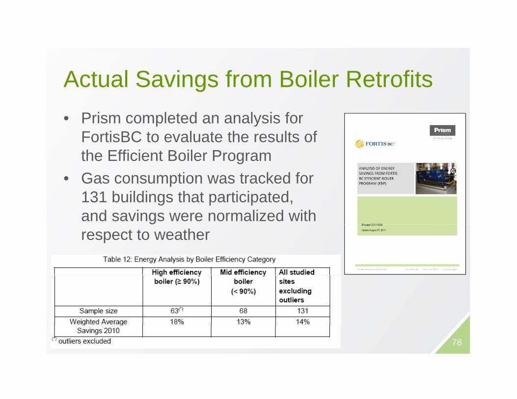
A t l S i f B il R t fitActual Savings from Boiler Retrofits• Prism completed an analysis for p y
FortisBC to evaluate the results of the Efficient Boiler ProgramG ti t k d f• Gas consumption was tracked for 131 buildings that participated, and savings were normalized with respect to weather
78
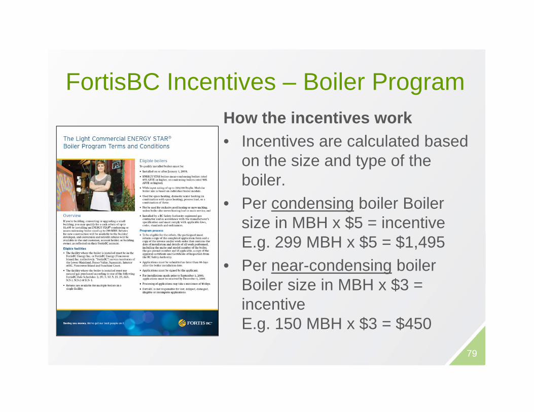
F ti BC I ti B il PFortisBC Incentives – Boiler ProgramHow the incentives work• Incentives are calculated based
on the size and type of the boilerboiler.
• Per condensing boiler Boiler size in MBH x $5 = incentiveE.g. 299 MBH x $5 = $1,495
• Per near-condensing boiler Boiler size in MBH x $3 =Boiler size in MBH x $3 = incentiveE.g. 150 MBH x $3 = $450
79
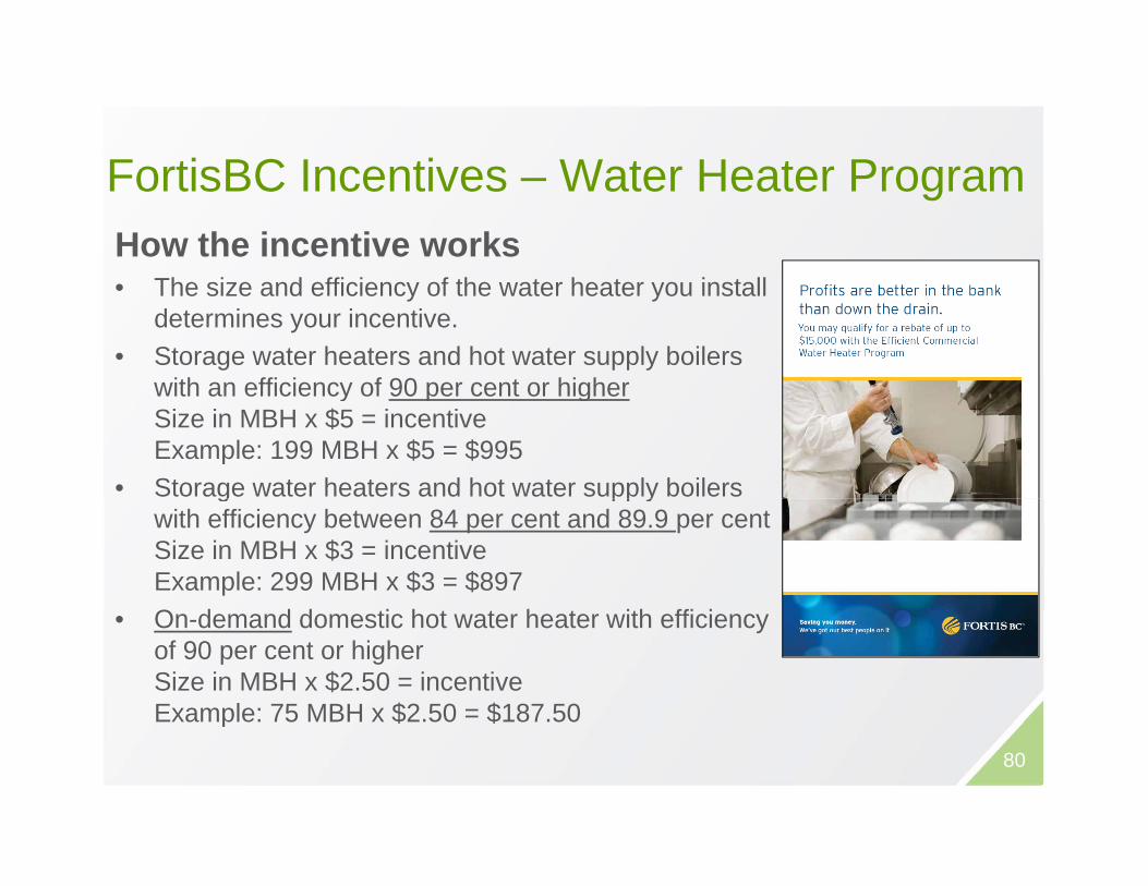
F ti BC I ti W t H t PFortisBC Incentives – Water Heater ProgramHow the incentive works• The size and efficiency of the water heater you install
determines your incentive. • Storage water heaters and hot water supply boilers
with an efficiency of 90 per cent or higherwith an efficiency of 90 per cent or higher Size in MBH x $5 = incentiveExample: 199 MBH x $5 = $995
• Storage water heaters and hot water supply boilers g pp ywith efficiency between 84 per cent and 89.9 per centSize in MBH x $3 = incentiveExample: 299 MBH x $3 = $897 O d d d ti h t t h t ith ffi i• On-demand domestic hot water heater with efficiency of 90 per cent or higherSize in MBH x $2.50 = incentiveExample: 75 MBH x $2.50 = $187.50p $ $
80
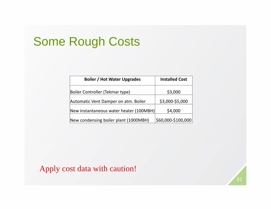
S R h C tSome Rough Costs
Boiler / Hot Water Upgrades Installed Cost
Boiler Controller (Tekmar type) $3 000Boiler Controller (Tekmar type) $3,000
Automatic Vent Damper on atm. Boiler $3,000‐$5,000
New instantaneous water heater (100MBH) $4,000
New condensing boiler plant (1000MBH) $60,000‐$100,000
Apply cost data with caution!81
Apply cost data with caution!

MOTORSMOTORS
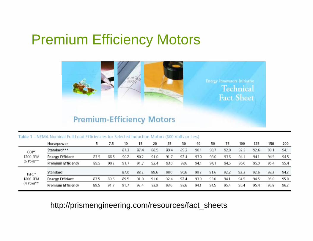
Premium Efficiency Motorsy
87.073.0
200200
EEStd
94.893.0
90.588.5
95.093.0
88.586.5
94.691.7
83.080.0
http://prismengineering.com/resources/fact_sheets
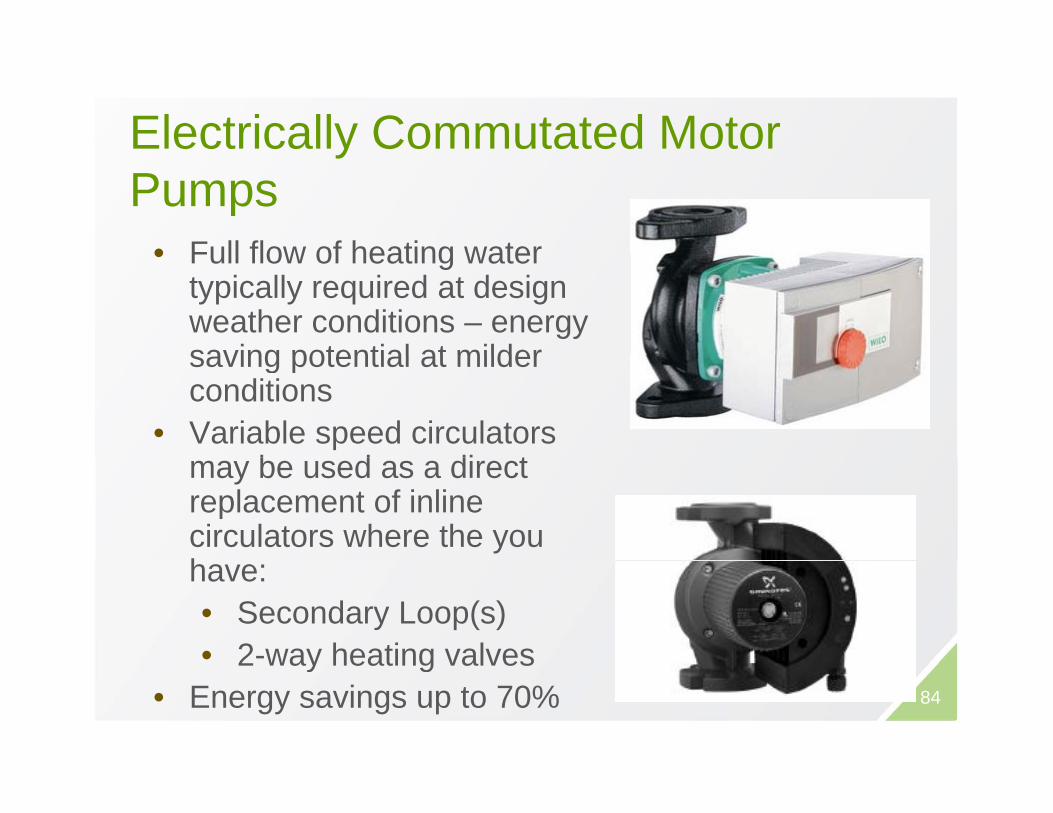
Electrically Commutated Motor yPumps
• Full flow of heating water• Full flow of heating water typically required at design weather conditions – energy saving potential at mildersaving potential at milder conditions
• Variable speed circulators b d di tmay be used as a direct
replacement of inline circulators where the you hhave:• Secondary Loop(s)• 2-way heating valves
84
2 way heating valves• Energy savings up to 70%
85

BC Hydro PIP Incentives – ECM yPumps
86
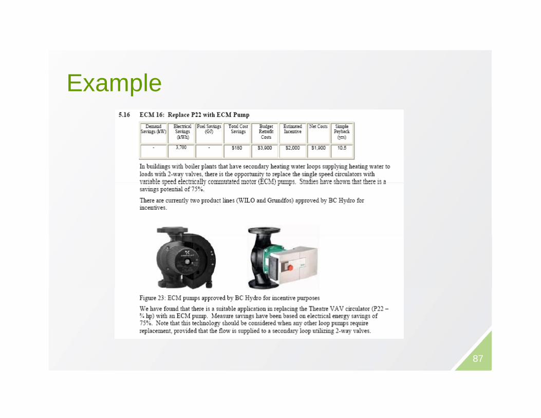
E lExample
87

REFRIGERATIONREFRIGERATION
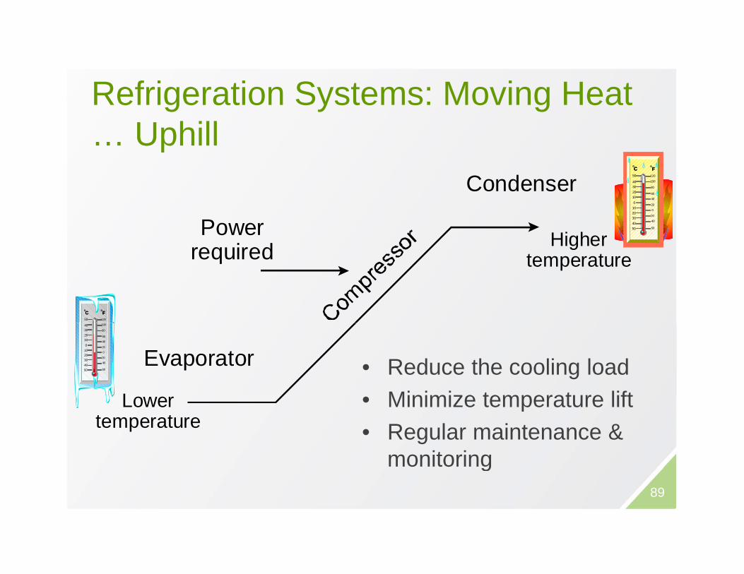
Refrigeration Systems: Moving Heat g y g… Uphill
C dFF
OO
CO
CO
50 120
Powerrequired Higher
Condenser 40302010 01020304050
100
80
0
20
20
40
60
6040
required temperature
50 120
FFOO
COCO
L
Evaporator
40302010 01020304050
100
80
0
20
20
40
60
60
40
• Reduce the cooling loadMinimize temperature liftLower
temperature• Minimize temperature lift• Regular maintenance &
monitoring89
g
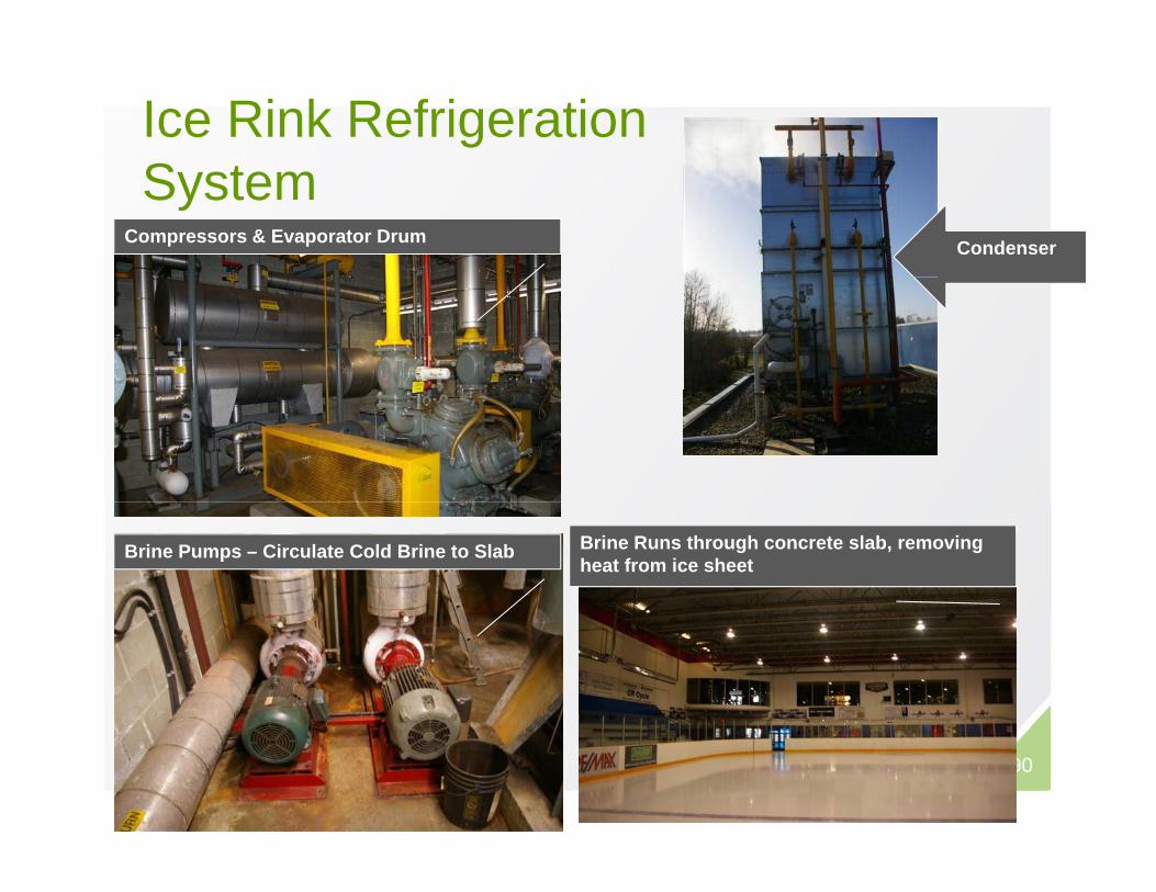
Ice Rink Refrigeration S tSystem
CondenserCompressors & Evaporator Drum
Brine Pumps – Circulate Cold Brine to Slab Brine Runs through concrete slab, removing heat from ice sheet
90
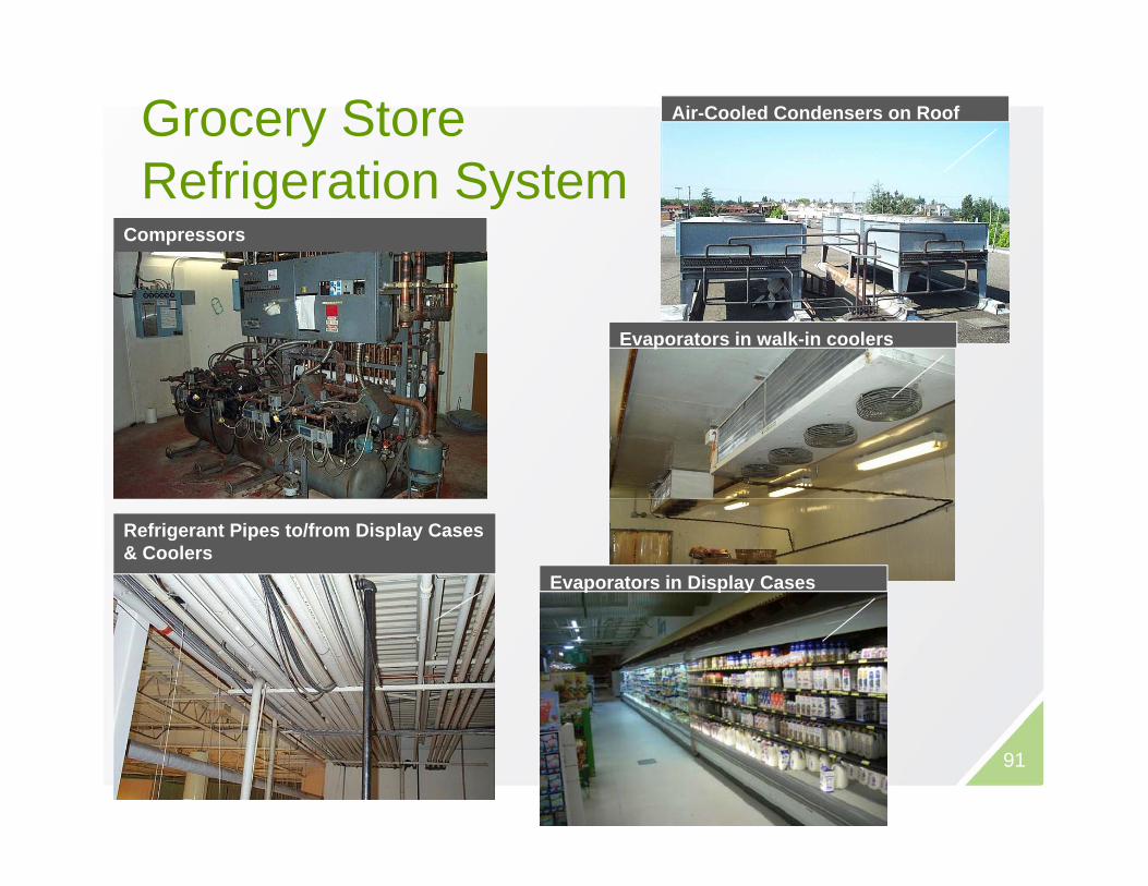
Grocery Store R f i ti S t
Air-Cooled Condensers on Roof
Refrigeration SystemCompressors
Evaporators in walk-in coolers
Refrigerant Pipes to/from Display Cases & Coolers
Evaporators in Display Cases
91
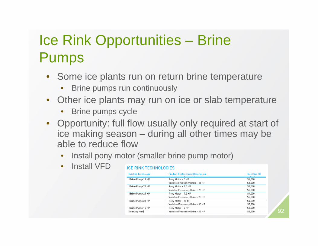
Ice Rink Opportunities – Brine ppPumps
• Some ice plants run on return brine temperature• Some ice plants run on return brine temperature • Brine pumps run continuously
• Other ice plants may run on ice or slab temperature• Brine pumps cycle
• Opportunity: full flow usually only required at start of ice making season – during all other times may be g g yable to reduce flow• Install pony motor (smaller brine pump motor)• Install VFD
92

Ice Rink Opportunities – Low e CeilingIce Rink Opportunities – Low e Ceiling• Even at low ceiling
temperatures (5°C), heat from ili i di t d t iceiling is radiated onto ice
surface• Highly reflective material (low
emissivity) prevents heat fromemissivity) prevents heat from being radiated onto rink– Reduce heat radiated onto ice
surface reduce refrigeration l dload
– $40-50k per installation
• For best performance, low-e t i l i t ll d b l limaterial installed below purlins
– May need new sprinkler heads– Requires dehumidified air to be
li d b t l d93
supplied between low-e and ceiling to prevent condensation

Grocery Store OpportunitiesGrocery Store Opportunities• Night Covers for vertical display
casescases• Anti-Sweat Heater Controls
– Older reach-in coolers have heaters to heat glass to prevent g pcondensation
– Opportunity: install controls w/ humidistat to only run heater when required
• ECM Fan Motors• Refrigerant Pipe Insulation
94
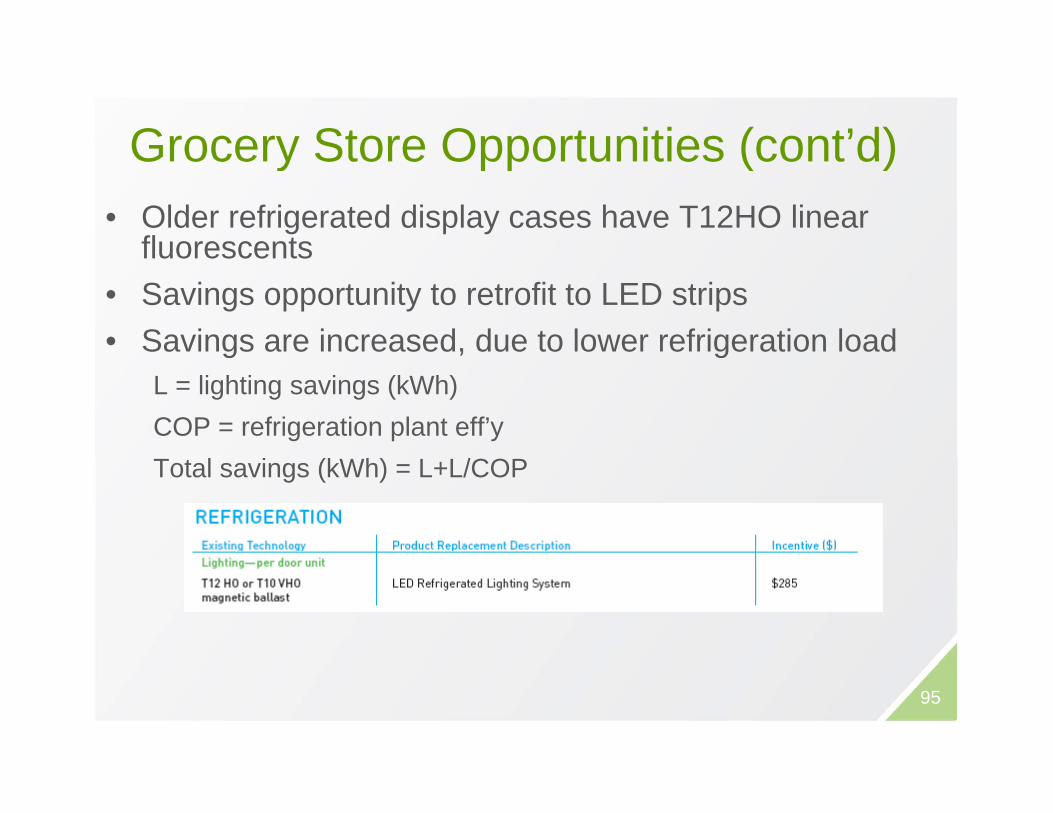
Grocery Store Opportunities (cont’d)Grocery Store Opportunities (cont d)• Older refrigerated display cases have T12HO linear
fluorescentsfluorescents• Savings opportunity to retrofit to LED strips• Savings are increased, due to lower refrigeration loadg , g
L = lighting savings (kWh)COP = refrigeration plant eff’y
( ) /COTotal savings (kWh) = L+L/COP
95

ResourcesResources
96

RETScreen® Energy Efficient Arena & Supermarket Project Model
• Calculates energy savings, life-cycle costs and greenhouse gascycle costs and greenhouse gasemissions reductions– For supermarkets & ice rinks– Process integrationProcess integration
(waste heat recovery)– Secondary loops to
reduce refrigerant lossesLighting and ceiling– Lighting and ceiling improvements
– Floating condenser pressure– Ice and concrete slab thickness– Other efficiency measures
www.retscreen.net
97

WRAP UP POINTSWRAP UP POINTS
F l S it hiFuel Switching
• Need to understand your unitsNeed to understand your units, conversions and equipment efficiency
• Equivalencies for fuel switchingEquivalencies for fuel switching– Is electric heating is cheaper than a
furnace?furnace?– How much heat do I lose in winter
switching to a CFL?switching to a CFL?
99
S i t idScenarios to consider
• Small building with gas-fired RTU andSmall building with gas fired RTU and numerous (10+) electric baseboards. How to achieve NSB?
• Condensing boiler installation. What would be a good application for this?would be a good application for this?
100

E S i T lbEnergy Savings Toolbox
A. Overview of Energy AuditingB. Energy Analysis MethodsC Technical SupplementsC. Technical Supplements
101Source: http://oee.nrcan.gc.ca/publications/infosource/pub/cipec/energy-audit-manual-and-tool.pdf Good Reference for this section – pg 140: Details of Energy-Consuming Systems

www.pumautilitymonitoring.ca

Thanks!Thanks!
Robert Greenwald, P.Eng., MBA, President320 - 3605 Gilmore Way, Burnaby, BC V5G 4X5604-205-550060 05 [email protected] www.prismengineering.com