Embed Size (px)
Citation preview

Lithophane TutorialLithophanes are images that can be created by limiting the amount of light that passesthrough a material. By changing the thickness of the material the amount of lightpassing through creates a contrast.
The material used must be translucent for the effect to work.
Lithophane History
Perhaps one of the most unusual and interesting art forms to emerge from theearly 19th century is the lithophane. Generally credited as being the inventionof Baron Paul de Bourguignon, of Rubelles, France, in 1827, the earliestforms of lithophanes were actually produced in China many years beforeother countries produced them. Chinese potters employed the process totrace floral designs in the delicate walls of eggshell thin porcelain vases.There is little historical evidence indicating the exact origins of this techniquein China, but it is certain that the knowledge predates the subsequentdiscovery by the Europeans. However, it was the Europeans that evolved theconcept from simple floral pictures into complex, intricately detailed scenes. Awide variety of images appeared on lithophanes. The subject matter includedquaint and delightful replicas of rural scenes and children at play,reproductions of famous portraits and popular paintings, dramatic religiousscenes, hunting images, and scenic panoramas.
It was the efforts of the Baron de Bourguignon that led to the great popularityof lithophanes during the mid-19th century. His concept was simply this: asheet of porcelain carved in varying degrees of thickness, when held to alight, would result in a highly detailed picture with the soft image quality of amezzotint. This simple concept however, was not easy to execute. Sheerartistry of high order was required to make a master carving from which thelithophanes could be moulded.
The very first lithophanes were individually carved entirely by hand. Butshortly after their introduction, the artists reasoned that moulds could bemade, from which numerous pieces could be cast. To produce these moulds,a sheet of wax was placed on a piece of plate glass. This provided sufficienttransparency for the artist's guidance. The full thickness of the wax on theglass stopped all light, and any scratch or gouge produced varying degrees ofgrey. Therefore, the entire range of shading from dark to bright was availablefor the skilled artisan to bring to life.
The artist first drew his general design on the surface of the white wax. Then,with modelling knives, burnishers, and other tools, he sculpted the minutedetails of the subject chosen for reproduction. From the wax carving, whenfinally approved by the master model maker, a plaster cast was made. Thiswas the original die, which was used in moulding the porcelain bisque. Amoist porcelain paste was then skilfully pressed into this cast, picking up all

the details in the carving. Close examination of this mould would revealintricate surface detail. During the porcelain casting process, the friction of theclay would swiftly wear these fine details out. To address this problem, theartists developed master moulds. Master moulds were made out of a harderplaster than the production moulds, and the image was reversed; like anegative. Production moulds were then cast from the master mould, allowingmany more lithophanes to be successfully cast.
The seemingly simple process of removing the thin moist panels from themoulds required the highest degree of skill to avoid damaging the intricatedetails in the image. Since the panels were very thin and delicate, and thekilns extremely hot, many fired pieces were warped, twisted, and cracked. Inaddition, any slight impurity in the porcelain clay body showed up when thefired pieces were lit from behind. Therefore, the number of acceptable finishedpieces to come out of the kilns has always been far less than the number thatwent in. Sometimes, only about 40 percent of the panels survived thisprocess. Since the earliest days of their production, these issues havechallenged the makers of lithophanes. Only the most determined craftsmencould overcome these difficulties, and go on to produce these brilliant artpieces.
During their heyday, lithophanes were produced by many potteries throughoutthe world. Some of the finest examples, as well as some of largest quantitiesof lithophanes were produced in Germany by the companies PrensaichPorzellan Manufactur in Plaue (P.P.M.), Berlin Porzellan Manufactur (B.P.M.),and Koniglichen Preussische Manufactur (K.P.M.). About 25 factories inBelgium, France, Denmark, Portugal, England, Italy, and Czechoslovakiaproduced lithophanes during the last century, with their popularity peaking inthe middle of the century. Some of the well-known companies involved inlithophane production were the Wedgwood and Worchester Potteries inEngland, Phoenix Pottery in Pennsylvania, Beleek in Ireland, and Limoge inFrance. Surprisingly, no individual lithophane artists have been identified,however, many pieces are marked with the manufacturer's name.
Lithophanes were hung in front of windows, where the sunlight streamingthrough the panel revealed the designs in the porcelain. Since lithophanesneed to be lit from behind be viewed properly, many beautiful types of lampswere made incorporating these porcelain artworks. Because of the era fromwhich they originated, most lithophane lamps were quite fanciful and ornate.Candle screens were quite popular. Typically, they consisted of a decorativeframe holding a lithophane, with a built-in candleholder to illuminate it from therear. Multipaneled lamps were also quite popular. These came in many forms.Some were ornate shades that would hold from four to six flat panels,mounted on a matching lamp base. These panels could be shaped asrectangles or trapezoids. Sometimes, a similarly constructed shade wasmade to hang from the ceiling instead. Other lamps, instead of utilizingmultiple panels, used one-piece hollow castings; cylindrical, conical, orsometimes round, with several images around their circumference. This typeof shade is quite rare and highly prized. Lithophanes were made to fit in"hurricane" type lamps, desk lamps, table lamps, ceiling lamps, wall sconces;

virtually any type of lighting fixture. A unique but popular vehicle for displayinglithophanes was the tea warmer. These ornate fixtures had lithophanessurrounding an enclosure, in which a candle was lit. Topping the enclosurewas a metal plate on which a teapot could be set, and kept warm from thecandle below.
Another popular application for lithophanes was to cast them into the bottomof drinking vessels. As one would finish his drink, a delicate image wouldappear in the bottom of the cup or mug. In Germany, many beer steins weremade with lithophanes in the base; sometimes with images that were quiterisqué! From Denmark, and France came beautiful tea and demitasse setswith lovely images in the bottom of the cup. In the early 20th-century,Japanese potteries began to produce lavishly decorated tea sets (calledDragonware) with images of geishas in the bottom. This practice becamequite popular in the post-WWII and Occupied Japan era for the GI trade inJapan. Production of these teacups tapered off in the 1950's, and a few arestill being made today. By the late 1800s, the bloom was off the rose, and thegreat popularity enjoyed by lithophanes began to fade. The potteries movedon to other items, and the highly evolved skills and techniques that the mastercraftsman had developed disappeared with the original artists as they passedaway. Since then, knowledgeable collectors, wise to the hidden beauty of thistruly remarkable art form, have avidly sought antique lithophanes.
Machined Lithophanes
Using the Denford Quick CAM and a CNC Machine lithophanes can bemachined from translucent materials in quite a simple process.
Unlike photographs and paintings the images will remain sharp and not fade.
Several parameters define how the machined part has to be machined.These include: material, colour, cutting tool, machine parameters and time.
Material
The material used to make lithophanes must be translucent, to test this, takean uncut piece of material, hold it to the light and pass your finger across theback of it. If you can see a dark shadow where your finger is the materialshould be suitable.
We have found that Cast Plexiglas that is 3mm (1/8”) thick is ideal for theprocess. While Plexiglas is available in both cast and extruded forms the castversion cuts better than the extruded form.
Other materials can also be machined with excellent results including Corien.Provided that the material is translucent and can be machined you canexperiment with machining Lithophanes.

Colour
Any colour of material will work provided the material is translucent though theones we have found to work best are Blue and White.
The darker the material the less light passes through so the thinner the reliefrequired to produce the image.
The light hits the materialtravelling from Left to Rightand is filtered by thematerial.
The thicker the material themore light is filtered and theimage appears to be darker.
Where the material is at itsthinnest most of the lightpasses through and theimage appears to be white.
If the material shown waswhite then more light wouldpass through the materialand the effect is the imagewould appear brighter.
To get more contrast with light coloured materials the relief’s have to bethicker.
Cutting Tool
The cutting tool is very important when manufacturing a lithophane. Thesmaller the tool tip, the finer the detail that can be produced.
If very small diameter tool tips are used. The tool will be more fragile willrequire higher spindle speeds to cut correctly
For each revolution of the tool you cancalculate the distance the tool surfacetravels.
The distance travelled per revolution is 3.14X Diameter of the tool.

For the 0.5mm diameter cutter the tool travels 1.57mm while the 2mmdiameter cutter travels 6.28mm
If you know the spindle revolves at 23000 RPM (Revolutions Per Minute) andyou know the diameter of the cutter you can calculate the distance travelled bythe tool diameter in a minute.
This is known as the tool surface speed.
For the 0.5mm Diameter tool the surface speed is:
23000 x 1.57 = 36110mm/Min or 36.11 M/min
For the 2mm diameter tool the surface speed is:
23000 x 6.28 = 144440mm/Min or 144.44 M/min.
When the tool cuts away the material the cut each revolution of the takes limitshow fast the tool can be moved without damaging the cutter.
In the example shown the tool is moving1mm in 5 revolutions. This means thatthe tool removes 0.2mm of material forevery revolution.
The programmed federate for thisexample would be 23000/5= 4.6M/min
Cutting Plexiglas the maximumfeedrate that you would want to useis about 3M/Min with the 0.5mmcutter.
A feedrate of 3M/minute gives the following values
Feedrate = 50mm/secondSpindle = 23000/60 = 383 Revs/second
At this feedrate the tool is revolving 7.6 times/mm so each cut is 0.13mm indepth.

Machine Parameters
The size and speed that lithophanes can be manufactured depends on thetype of machine you have.
Routers typically have a high spindle speed, which result in the tool having ahigh surface speed, which in turn allows higher feedrates to be used.
Milling machines have much lower spindle speed and as a result the feedratesused must be slower than that of a router. Using a larger diameter cutter on amilling machine will increase the surface speed and allow higher feeds to beused but reduces the resolution of the image produced.
The maximum size of lithophane that can be produced depends on the bedsize of the machine being used.
The best machines for producing Lithophanes are routers as they have higherfeeds and spindle speeds and a larger work area.
Time
The time taken to produce a lithophane is dependent on the size of the image,the speed and feeds used in the program and the tool step over programmed.
When manufacturing a lithophane the Z (vertical) axis makes lots of movesboth up and down. Each time the axis reverses the slides must stop thenreverse. This prevents the other axes achieving the full-programmed speed.
The larger the image the further the X or Y-axis move before an axis reversalso the faster the actual feedrate.
Images with large areas of one solid colour will be machined faster as there isno z-axis move over this area, so the tool accelerates to the programmed feedthen moves to the next direction reversal before decelerating.
The larger the lithophane the longer it will take to manufacture. Therelationship of size to time is not however linier. A 100mm x 100mm model willnot be 4 times faster than a 200mm x 200mm model. This is because therewill be a similar number of Z-axis reversals in each program so the moves in-between are longer and therefore able to achieve a higher feedrate.
Editing a Photograph Prior to Machining
A photograph can be edited prior to manufacture to reduce the manufacturetime and to increase the definition and contrast.
While editing is not essential it can improve the finished result.

In the following examples a photograph is edited to give an ideal image tomachine.
The photograph to the right wastaken at high resolution andincludes a complicated background.
While the image can be machinedthe background is not the part wewant to view.
Use any photo editing package tocut the part of the photograph thatyou want to manufacture and savewith another name.
The photograph has been cut downto show the part that will bemachined.
Using a package like Photoshopthe background can be cut away toleave just the image that you wantto machine.

The background can be filled and ifrequired a border added as shown.
The manufacturing time for thisedited image will be reducedsubstantially and the resultantlithophane will have more detailbecause the subject has beenenlarged.
Using Quick CAM 3D to produce a Lithophane
Open Quick CAM 3D from the start Menu or Desktop Icon.
Quick CAM 3D is a simple to use“Wizard Program”. The openingscreen is shown.
This tutorial will take you throughproducing a Lithophane from importinga photo to machining the part.
In addition to this tutorialthere is a comprehensivehelp library, which can beaccessed by clicking theHelp Menu command orpressing the F1 Key.
Identifying the parts of the Quick CAM 3D Wizard
The picture below identifies the key areas of the wizard screen.
Useful tips are displayed in each menu page above the stage navigation
section by the “i “symbol.
Using the Help
While it is possible to open the help from the Help Menu on the top toolbar it isbetter to use the “F1” key.
When you press the “F1” key you get context sensitive help. This means thatif you are on the opening screen of the software and you press F1 the Helpwill open on the page relating to opening 3D Models or an Image file.
If you scroll down the right hand side of the help you will find the section onimporting a 2D image.

At the bottom of the section there isinformation that explains how tomanipulate the image file.
Close the Help by clicking on theX in the top right hand corner ofthe help window.
OPEN MODEL / BMP
To import an image file click on the button.
A brows window opens and gives apreview if an image file is selected.
Browse for the desired image thenclick on the image to see thepreview.
Note: The display of the files maynot show thumbnails unless thisoption has been selected.
Click on the dropdown menu shownto select the file view you require.
Thumbnail view may not beavailable on some operatingsystems.
Once you have the file you want to manufacture selected click
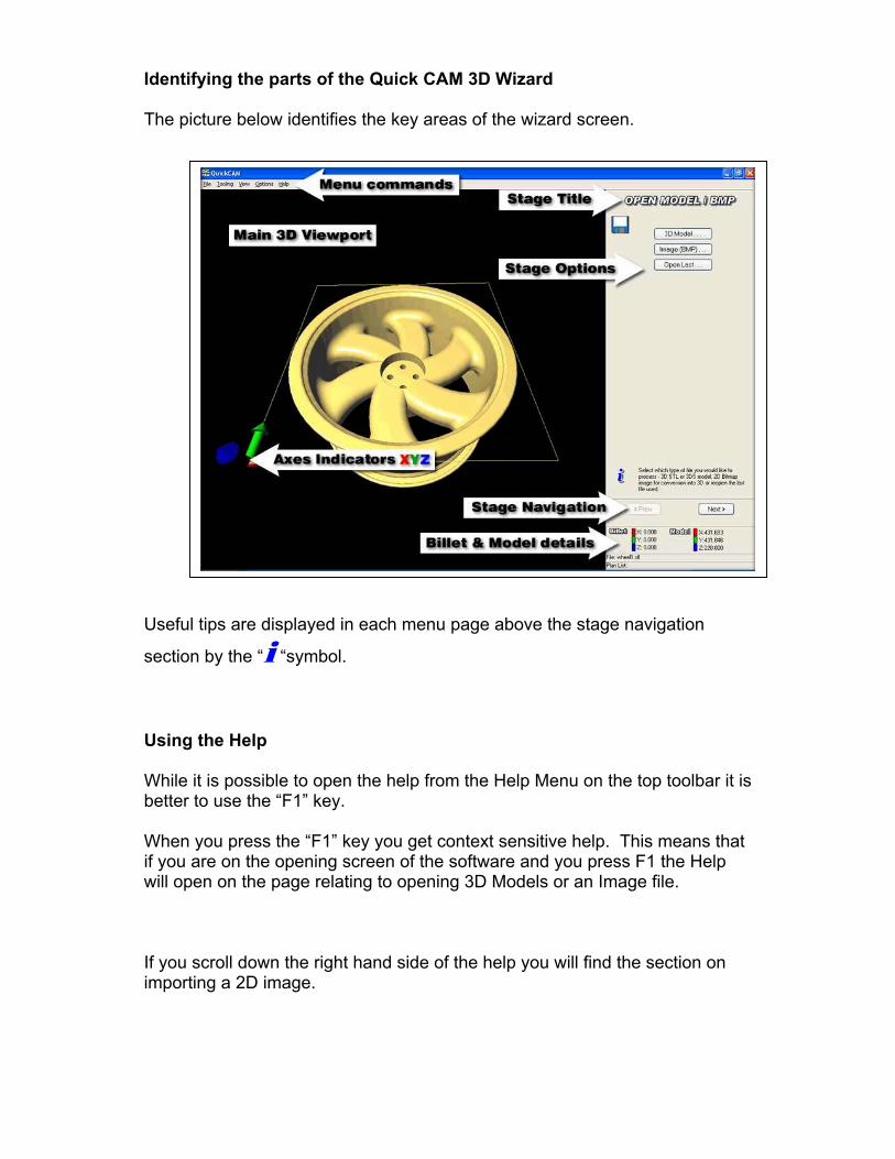
The image opens by default ingreyscale and at low resolution.
The quality of the image requireddepends on the size you wish tomanufacture at.
The larger the required part the higherthe required image quality.
Using the High setting will work for allsizes but will result in larger programsthat take longer to produce than isrequired.
Typically you should set the resolution as follows:
Low
For parts that are less than 100mm in size or are very high resolution picturesto begin with.
Medium
For parts that are less than 150mm in size or pictures with a lower resolution.
High
For any part over 200mm in size or for pictures of low quality.
Note:
Selecting low quality will give an image model accuracy of about 2.5 pixels permm on a 100mm wide image model.
Selecting medium quality will give an image model accuracy of about 3 pixelsper mm on a 100mm wide image model.
Selecting high quality will give an image model accuracy of about 5 pixels permm on a 100mm wide image model.
Select the file “High” Quality output.
You will have to wait while the image is resized.

Once the file has resized at highquality select OK.
The image will then be opened in theMain 3D Viewport.
The picture will be positioned in theMain 3D Viewport with the zoomlevel set to whatever the image sizeis.
Click the View Reset from the MenuCommand bar and the image willreturn to a default view.
Note:The View Reset command is a usefultool and can be used throughout thewizard.
The view can be changed using the commands below:
Clicking anywhere in the Main 3D Viewport with the mouse, will manipulatethe current 3D display.
Click and hold the left mouse buttonwhile moving the mouse to rotate theobject.
Click and hold the right mousebutton while moving the mouse tozoom, making the object closer orfurther away.
Click and hold both left and rightmouse buttons while moving themouse, to shift the object up-down orleft-right.
Click “Next” once you have rotated your view to look like the one above.

Set Billet Size
In this window you will define thesize of the material used to machinethe part in.
The thickness will default to 3mmthe X and Y values should be set tomatch the billet (work piece) size.
View Reset will auto size the Billetand give a plan view.
You can pan zoom and rotate usingthe mouse in the same way asbefore.
Set the billet size to:
X100Y100Z3
Once the Billet has been defined click next.
Set Model Size
In this window the size of thephotograph is scaled onto the Billetand the finished relief will be madethe size of the image shown.
The image is automatically scaled aslarge as possible without exceedingthe bounds of the billet as it isimported.
The scale that the image has beenimported at is a good indication as toif the quality setting was setcorrectly.
In this case the scale is 20% indicating that the image is of a high quality. Ifthe image imports at 100% then it is the optimum for machining. If the value isover 100% then it may be worth going back through the wizard and increasingthe quality.

If you are unable to increase the quality any further then you must accept thefinished part resolution may be reduced as a result of a poor quality inputimage.
If the Scale is less than 100% then you will have enough data to produce agood image.
The smaller the value the more data that is used and the longer theprocessing and cutting time will be but the better the finished part.
When you produce the finished partyou want there to be a borderaround the model.
All the dimensions are linked sochanging any of the X, Y or Scalevalues will change the linkedvalues.
In this case the X value is set to100mm or the width of the block, soyou will change this value.
Changing the X value to 90mm leaves a 5mmborder at the left and right of the image.
A larger gap is left top to bottom.
It is also possible to rotate the image at thispoint but you must be careful to keep the modelwithin the limits of the billet otherwise you willbe unable to proceed.
Once you have set the model size within the Billet click Next.
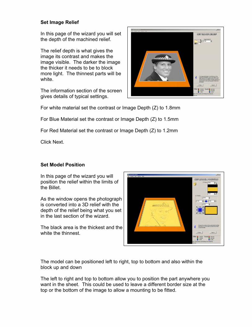
Set Image Relief
In this page of the wizard you will setthe depth of the machined relief.
The relief depth is what gives theimage its contrast and makes theimage visible. The darker the imagethe thicker it needs to be to blockmore light. The thinnest parts will bewhite.
The information section of the screengives details of typical settings.
For white material set the contrast or Image Depth (Z) to 1.8mm
For Blue Material set the contrast or Image Depth (Z) to 1.5mm
For Red Material set the contrast or Image Depth (Z) to 1.2mm
Click Next.
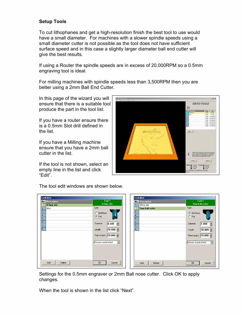
Set Model Position
In this page of the wizard you willposition the relief within the limits ofthe Billet.
As the window opens the photographis converted into a 3D relief with thedepth of the relief being what you setin the last section of the wizard.
The black area is the thickest and thewhite the thinnest.
The model can be positioned left to right, top to bottom and also within theblock up and down
The left to right and top to bottom allow you to position the part anywhere youwant in the sheet. This could be used to leave a different border size at thetop or the bottom of the image to allow a mounting to be fitted.

The Z Position is used to set the distancefrom the bottom of the material to thebottom of the relief.
As shown here the Lower z value is 0.5mm,this means that the white parts of the imageare 0.5mm from the bottom of the billet.
The X - Y position can be changed inseveral ways: grabbing the orange blockand dragging it, editing the values in the X,Y windows or by clicking in any of the 9blue windows with arrows in.
Set the Z Position as shown 0.5mm fromthe bottom of the block
Set the X and Y to the centre of the blockby clicking on the Centre blue button asshown
Click Next.
Set Boundary
This window is used to select thearea around the model that you maywant to machine. In most cases youjust want to machine the model itselfso the default values are used.
Set the values as shown.
Click Next
Setup Tools
To cut lithophanes and get a high-resolution finish the best tool to use wouldhave a small diameter. For machines with a slower spindle speeds using asmall diameter cutter is not possible as the tool does not have sufficientsurface speed and in this case a slightly larger diameter ball end cutter willgive the best results.
If using a Router the spindle speeds are in excess of 20,000RPM so a 0.5mmengraving tool is ideal.
For milling machines with spindle speeds less than 3,500RPM then you arebetter using a 2mm Ball End Cutter.
In this page of the wizard you willensure that there is a suitable tool toproduce the part in the tool list.
If you have a router ensure thereis a 0.5mm Slot drill defined inthe list.
If you have a Milling machineensure that you have a 2mm ballcutter in the list.
If the tool is not shown, select anempty line in the list and click“Edit”.
The tool edit windows are shown below.
Settings for the 0.5mm engraver or 2mm Ball nose cutter. Click OK to applychanges.
When the tool is shown in the list click “Next”.

Machining Plans
In this page of the wizard you willgenerate the machining plan orcutter path that will be used tomachine the lithophane.
Quick CAM 3D has only two types ofmachining plan available but otherscan be found in Quick CAM PRO.
Press the “F1” key to display thehelp.
The Help file will explain how todefine the cutting plans available.
For cutting Lithophanes in 3mmmaterial there is no need to make aroughing pass.
The raster-finishing plan is ideal forcutting lithophanes.
Expand the Machining plans helpmenu by clicking the + symbol to theleft of the option.
The help menu explains what all thecutting plans do and why you woulduse them.
Read the information relating toRaster Finishing.

Select the Add option from the PlanList.
You will now select the Rasterfinishing Plan from the Menu.
This will open up a window thatallows you to edit the parametersthat will be used to create the toolpath.
Depending upon which type ofmachine and tooling you have willdefine the parameters to use.
If you have the 0.5mm Slot drilldefined select it from the tool datadropdown. This is ideal for routers ormachines with a high spindle speed.
If you have a milling machine selectthe 2mm Ball end Cutter from the list.
0.5mm Engraving Cutter Settings
Step Over 40%Feedrate 3000Spindle Speed 23000Safe Height 5.00Raster Angle 0
These are typical values for cutting a lithophane with this type of tool. A StepOver of 30% will improve the finish but take longer to machine. A Step Over of60% will reduce the manufacture time but the finished part will not be as welldefined.

2mm Ball End Cutter
Step Over 15%Feedrate 300Spindle Speed 2500Safe Height 5.00Raster Angle 0
These are typical values for cutting a lithophane with this type of tool. A StepOver of 10% will improve the finish but take longer to machine. A Step Over of30% will reduce the manufacture time but the finished part will not be as welldefined.
You should program the maximum spindle speed your machine is capable ofdoing as the spindle speed value.
Once you have defined the cutter parameters for the plan click “OK”.
A calculating bar will appear as thetool path is generated
Once the tool path is complete it willbe displayed over the model
The tool path is can be seen over themodel. If you zoom in you will seethis clearly.
The completed plan is show in theplan list.
Click “Next”.

Tool path Simulation
Use the View Reset command fromthe Menu Command toolbar.
Zoom the display as shown.
Clicking play on the simulation toolbar will simulate the tool path.
Hover over each of the tool pathsimulation keys and a hint as tothe function is displayed.
The Turbo button is on by default.Click this button and switch Turbooff.
When the simulation is playingand turbo is off every line of thesimulation is displayed.If turbo is on the graphics are updated less frequently to speed up thesimulation.
Press stop and the simulation stops and the display is shown at full resolution.
If you press play now the program will re-simulate from the beginning.
Press pause and the program stops. Pressing play will resume the simulationfrom the point where it was paused.
The Camera button allows a pictureof the simulation to be saved and is asnapshot of the onscreen simulation.
The speed slider will allow thesimulation to run faster by displayingthe simulation at a lower resolution.
When the simulation finishes the finalpart is displayed, as it will bemachined.

The finished part will look like thisif cut with the 0.5mm slot drill.
In this case because the tooldiameter is smaller the definitionof the Lithophane is very good.
The finished part cut with the 2mmBall End Cutter will be as shown.
While the image is not as sharp asthe one cut with the smaller tool it willstill be clear.
Once the simulation is complete Click “Next”

CNC File Output
In this page of the wizard you will definethe Datum position the machine will useand then save the CNC file.
The origin will default to X0 Y0 Z0 andfor nearly all instances this will be therequired value.
If you wish to use another Datumposition press “F1” for help.
Click the “Create CNC File” button to save the file.
Browse to the place where you want tosave your file.
Name the file then click “Save”
Depending on the configuration of your installation the VR Milling mayautomatically load in which case the file will appear as the current program inthe editor.
If VR Milling is not installed or not configured to auto run then you will need tostart the VR milling software and open the FNC file in the normal way.
VR Milling shown with the programloaded to the editor.
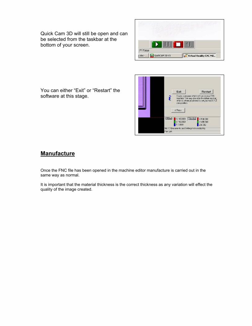
Quick Cam 3D will still be open and canbe selected from the taskbar at thebottom of your screen.
You can either “Exit” or “Restart” thesoftware at this stage.
Manufacture
Once the FNC file has been opened in the machine editor manufacture is carried out in thesame way as normal.
It is important that the material thickness is the correct thickness as any variation will effect thequality of the image created.