Embed Size (px)
Citation preview

NBSIR 73-316
(AFAPL-TR-73-72)
LIQUID HELIUM PUMPS
Philip M. McConnell
Cryogenics Division
Institute for Basic Standards
National Bureau of Standards
Boulder, Colorado 80302
Interim Report
June 1973
Prepared for
Air Force Aero Propulsion Laboratory
Air Force Systems CommandWright-Patterson Air Force Base; Ohio 45433


NBSIR 73-316
(AFAPLTR-73-72)
LIQUID HELIUM PUMPS
Philip M. McConnell
Cryogenics Division
Institute for Basic Standards
National Bureau of Standards
Boulder, Colorado 80302
Interim Report
June 1973
Prepared for
Air Force Aero Propulsion Laboratory
Air Force Systems CommandWright-Patterson Air Force Base; Ohio 45433
U.S. DEPARTMENT OF COMMERCE, Frederick B. Dent, Secretary
NATIONAL BUREAU OF STANDARDS. Richard W Roberts. Director

NOTICE
When Government drawings, specifications, or other data are used for any
purpose other than in connection with a definitely related Government
procurement operation, the United States Government thereby incurs no
responsibility nor any obligation whatsoever; and the fact that the
government may have formulated, furnished, cr in any way supplied the said
drawings, specifications, or other data, is not to be regarded by implication
or otherwise as in any manner licensing the holder or any other person
or corporation, or conveying any rights or permission to manufacture, use,
or sell any patented invention that may in any way be related thereto.
Copies of this report should not be returned unless return is required by
security considerations, contractual obligations, or notice on a specific
document.
ii
FOREWORD
This program was completed under sponsorship of the Departmentof the Air Force, Wright -Patter son Air Force Base, Ohio, and wasfunded with FY 1972 AF Aero Propulsion Laboratory Director's Funds.
This Technical Report has been reviewed and is approved for
publication.
The joint contributions of Lou Schafer of the Sundstrand Corpora-tion, Rockford, Illinois, who provided the submersible motor and JimLobach of the Barber -Nichols Engineering Company, Denver, Colorado,
who designed the pump (under contract), are gratefully acknowledged bythe author. * Thanks is given to K. Nuss, who machined the pump parts.
The author is grateful to V. Arp for his review of the manuscript and
his helpful suggestions throughout the course of this work. Special
thanks is also given to J. Hord for his consultative contributions.
Philip M. McConnell's present affiliation is the Todd Shipbuilding
Company, Research and Development Division, Galveston, Texas 77550.
FOR THE COMMANDER
DR. P/E. STOVERGS-15Chief, Power Distribution BranchAerospace Power Division
ACKNOWLEDGMENTS
iii

Nomenclature
area of orifice
impeller width at discharge
height of the centrifugal impeller vanes
meridional velocity at inlet tip
discharge coefficient
constants in temperature -
resistance calibration correlation
centrifugal impeller diameter
inducer hub diameter
^D^ (1 2 v )/2, mean effective,
inducer diameter
inducer tip diameter
elastic modulus
mechanical energy losses per unit mass
per unit time
local acceleration of gravity
total dynamic head
thermal strain
rate of mass flow at pump discharge
pump rotative speed
(9. 7961 m/s2
)
iv
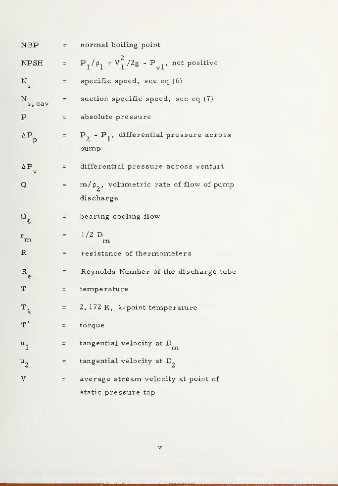
normal boiling point
2Pj/ Pj + /2g - P net positive
specific speed, see eq (6)
suction specific speed, see eq (7)
absolute pressure
P^ - Pj, differential pressure across
pump
differential pressure across venturi
m /
P
9 > volumetric rate of flow of pump
discharge
bearing cooling flow
1/2 Dmresistance of thermometers
Reynolds Number of the discharge tube
temperature
2. 172 K, \-point temperature
torque
tangential velocity at
tangential velocity at
average stream velocity at point of
static pressure tap
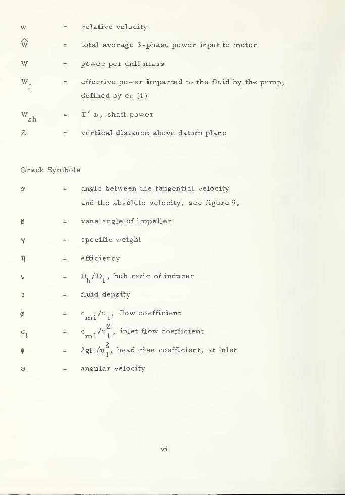
w = relative velocity
W = total average 3-phase power input to motor
W = power per unit mass
= effective power imparted to the fluid by the pump,
defined by eq (4 )
W , = T' U) , shaft powersh
Z = vertical distance above datum plane
Greek Symbols
a - angle between the tangential velocity
and the absolute velocity, see figure 9.
(3 - vane angle of impeller
Y = specific weight
T\ = efficiency
v = D^/D^, hub ratio of inducer
p = fluid density
0 = c /u , flow coefficientml 1
cp, = c /u^ , inlet flow coefficient1 ml 1
2f = 2gH/Uj, head rise coefficient, at inlet
ou = angular velocity
vi

inlet
discharge
bearing cooling passage
critical
cavitating
hydraulic
liquid
motor
normal fluid
non- cavitating
pump
superfluid
total
ullage
vapor, volumetric
saturated vapor at inlet
vii

CONTENTS
Page
1. Introduction . 1
2. Pump Characterization 4
2. 1 Mechanical Energy Balance 4
2. 2 Pump Performance and Characteristics .... 7
2. 3 Affinity Laws 10
2. 4 Stability 11
2. 5 Helium Pump Cavitation 12
2. 6 Pump Efficiency 17
2.7 Reliability 19
3. Survey Results 20
3. 1 Literature Review 20
3. 2 Commercially Available Pumps ....... 28
4. Pump Tests . 34
4. 1 Description of the Tested Pump 34
4. 2 Test Loop and Instrumentation ....... 40
4. 3 Results of Pump Test ......... 46
4. 3. 1 LHe I, 2. 3 K < T < 4. 3 K 50
4.3.2 Supercritical Helium, 4. 7 K < T < 5. 6 K . 59
4.3.3 LHe II, 1. 8 K < T < T. ....... 61A.
4. 3. 4 Comparison of the H-Q Data 66
4. 3. 5 Reliability ........... 66
5„ Conclusions ................ 68
6. Recommendations for Future Work 70
7. References 72
viii

LIST OF FIGURES
Page4
Figure 1. Phase diagram for He 3
Figure 2. Schematic diagram of a liquid helium pumping
system 5
Figure 3. Typical steady state performance characteristics
of a vaneaxial blower ........... 12
Figure 4. Predicted LHe I cavitation performance of a
67. 8 mm inlet diameter, centrifugal pump;
rotative speed 25,000 rpm; inlet flow coefficient,
0 = c /U = 0. 225 161 rrij 1
Figure 5. Axial flow inducer; brass vanes are silver
soldered into cuts in the hub 35
Figure 6. Centrifugal impeller for helium pump, 6061 -T6
aluminum, anodized finish 36
Figure 7. Photograph of helium pump parts 37
Figure 8. Assembly drawing of helium pump and
submersible motor „ 38
Figure 9. Inlet and discharge velocity triangles based on
the design criteria 39
Figure 10. Schematic diagram of He - pump test loop and
instrumentation 41
Figure 11. Venturi flow meter used in helium pump tests . . 47
Figure 12. Typical performance characteristics of
He - pump operating in LHe I; T = 4. 15 K;
n = 631 rad/s (6030 rpm); 0. 19 m £ NPSH < 0. 7 m . 53
Figure 13. Total dynamic head-capacity performance
curves in LHe I; 3. 18 K < T < 4. 15 K 55
ix
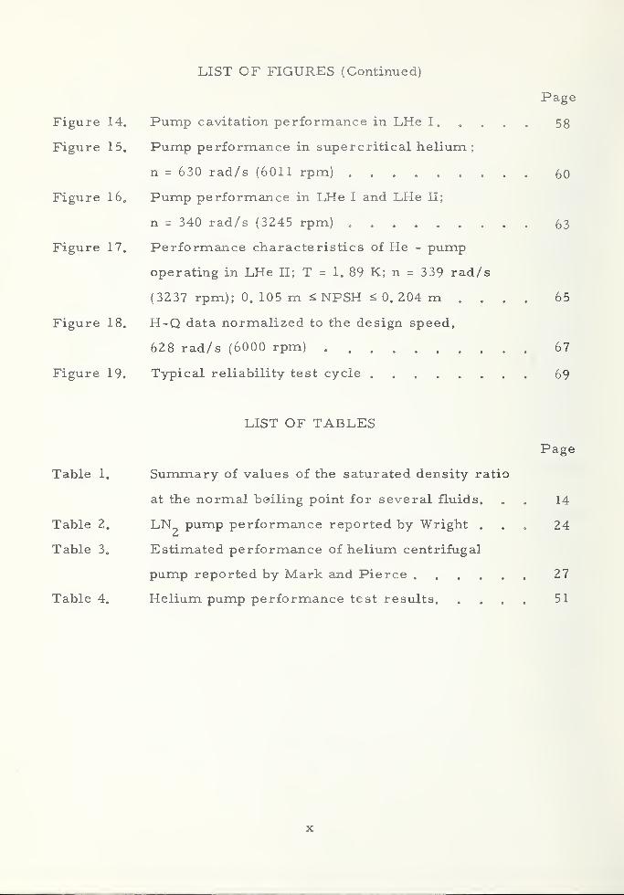
LIST OF FIGURES (Continued)
Page
Figure 14. Pump cavitation performance in LHe 1 58
Figure 15. Pump performance in supercritical helium;
n = 630 rad/s (6011 rpm) 60
Figure 16. Pump performance in LHe I and LHe II;
n = 340 rad/s (3245 rpm) 63
Figure 17. Performance characteristics of He - pump
operating in LHe II; T = 1. 89 K; n = 339 rad/s
(3237 rpm); 0. 105 m £ NPSH ^ 0. 204 m .... 65
Figure 18. H-Q data normalized to the design speed,
628 rad/s (6000 rpm) 67
Figure 19. Typical reliability test cycle 69
LIST OF TABLES
Page
Table 1. Summary of values of the saturated density ratio
at the normal boiling point for several fluids. . . 14
Table 2. PumP Perf°rmance reported by Wright ... 24
Table 3. Estimated performance of helium centrifugal
pump reported by Mark and Pierce 27
Table 4. Helium pump performance test results. .... 51
x

ABSTRACT
This report summarizes studies of pump charac-
teristics and performance in supercritical, normally
boiling, and superfluid helium, and also presents results
on a survey of commercially available pumps for helium
service. Experimental measurements were made on a
centrifugal pump which produced a maximum head of about-4 3
15 meters, and a maximum flow of about 2. 5x10 m/s„Performance agreed approximately with classical affinity
laws, but cavitation appeared to provide less of a perform-
ance limitation than expected. The survey turned up
several pumps which have been used in helium, though
relevant performance data is lacking.
Key words: Cavitation; helium; pump performance; pumps;
superfluid.
xi

Liquid Helium Pumps*
Philip M. McConnell t
1. Introduction
Pumps are presently being used [1-4], ^ or considered [5], to
provide forced helium cooling of superconductive magnets and power
transmission lines. However, there exists little experience in pumping
helium, and no pump performance characteristics with low temperature
helium (2 K < T < 8 K) have previously been reported in the literature.
Therefore, design and performance characteristics have been largely
speculative.
A basic question which we wish to examine in this study is: What
unique features are involved in the pumping of helium? The low latent
heat of vaporization (about 22 J/g at 4K), low viscosity, and super-
fluidity are some of the unusual properties of helium (2 K < T < 8 K)
which could give rise to unpredictable pump performance. On the other
hand, if the helium is single phase and Newtonian, helium pumping
should be similar to the pumping of single phase, low temperature
hydrogen (or other cryogenic fluids); in this case the considerable work
which has already been done [2, 6, 7, 8, 9, 10] could be used to advan-
tage. Actual helium data are obviously needed to verify the feasibility
and reliability of using conventional pumps to transfer the various fluid
phases (e. g, , LHe II, LHe I, two-phase helium, and supercritical helium),
This program was funded with FY-1972 AF Aero Propulsion Laboratory
Director's funds, Wright-Patterson AFB, Ohio,
tPresent affiliation: Todd Shipbuilding Company, Research and
and Development Division, Galveston, Texas 77550.
Figures in brackets indicate the literature references at the end of
this paper.

to verify the pump affinity laws [11], and to check the validity of accu-
rately predicting helium pump performance using less expensive fluids e
The phase diagram for helium is shown in figure 1 (not to scale).
Systems currently under study require intermittent cooling flow rates-3 3
which are greater than 1.9 x 10 m /s (30 gal/min) at relatively low
differential pressures. With this in mind, the study has been rather
arbitrarily limited to include pumps whose design capacities are less-3 3
than 6. 3 x 10 m /s (100 gal/min) with relatively low total head, and
to helium inlet temperatures between 2 and 8 K. The helium thermo-
dynamic and transport properties, necessary for any pump analysis,
are well known for these flow conditions [12].
The characterization of pumps for helium service is discussed
in general terms in section 2. , wherein we summarize the origin of
some of the important pump parameters and their applications. Although
many of these parameters were developed from work solely on impeller
pumps, they can be meaningful when applied to other types of pumps,
e. g. ,ejector pumps [13]. More comprehensive treatments of impeller
pump design, performance, and similarity parameters are given by
Wislicenus [14], Stepanoff [11], and Kovats [15], and Lazarkiewicz and
Troskolanski [16], Other pump types such as reciprocating pumps and
gear pumps were also of interest, but few of these types are found for
low temperature use. Also included are practical considerations involved
in pumping helium- -e. g. ,cavitation, stability of the pump, bearings,
types of motor drives, etc.
The results of a survey of helium pumps are given in section 3.
It includes results of an extensive review of the literature of helium
pumps, and results of personal communication with various pump manu-
facturers whose products may be applicable for helium service.
2

\
3

In section 4 we describe our own laboratory tests of a small cen--4 3
trifugal helium pump designed for flows up to Z. 5 x 10 m /s (4 gpm)
with a total dynamic head of 15 meters, characteristics which may be
useful for various superconductor applications where forced flow cooling
may be required.
2. Pump Characterization
2. 1 Mechanical Energy Balance
A typical liquid helium pumping system is shown in figure 2. The
pump motor may be operated at ambient temperature, location a, or
submerged in the fluid, position b. Both of the configurations have
their advantages and disadvantages , which will be discussed later. The
superconducting system may be located in the pump dewar or in a
remotely located dewar, depending on the particular application.
The steady state mechanical energy balance [17], applied to the
pump between the inlet and discharge (planes 1 and 2, respectively),
can be written per unit mass per unit time as
2 2AV f dP /\ /\
+ g A Z + ~ - "W + E = 0 , (1)J
12 J j P v
where the numbers 1 1' and '2' denote the measured inlet and outlet
/\stream conditions respectively, W is the specific power input to the
pump, and E is the rate at which mechanical energy is irreversibly
converted to thermal energy, i. e. , friction losses. For an isentropic
process, E is equal to the rate of heat removal through the pump
casing between 1 and 2. Assumptions made in the derivation of ( 1
)
are that the flow is turbulent and that the gravitational acceleration,
g, remains constant throughout the system. The first three terms
in (1) represent the fluid or useful power per unit mass, W., imparted
to the fluid by the pump. The pump efficiency defined as
4

Vent
Pu.T
LHe
a
Delivery
Valve
. fJU ^To SuperconductingSystem
q (Heat Leak)
1AZ
• 2
Figure 2. Schematic diagram of a liquid helium pumping system.
W„ W - E
1 = 7C = <2 »
w w
is determined from measurements of all the terms in (1) other than/\E . Since continuity of mass requires that rh - m = m, T| = W /W ,
v 1 2 f sh
where is the fluid power and W ^ is the shaft power to the pump.
It is sometimes convenient to divide (1) by g. In this case, the first
three terms are referred to as the total dynamic head (H), where
2 2AV 1 r dPH =^~+ A Z + — i —
. (3)2 g g J
jP
5

The first two terms in eq (3) are usually much less than the third. The
H has dimensions of length (usually expressed in units of the working
fluid as characterized by the inlet stream conditions), and for a given
pump operating at a constant speed and volume flow rate is (approxi-
mately) independent of the fluid being pumped. The fluid power can be
expressed in terms of H as
Wf
= mg (H) =Yl Q 1
(H) = Y2 Q 2
(H) (4)
where m and Q are the rates of mass and volumetric flow, respectively,
through the pump, and y is the specific weight of the fluid.
In order to evaluate the integral in eqs (1) and (3) along a repre-
sentative streamline, one must know the equation of state, p = (P, T),
how T changes with P along the streamline, and the thermodynamic
path of the process from 1 to 2. For the special cases of an isother-
mal system, p = p (P) , and isentropic flow of an ideal gas, the integral
may be easily evaluated. In the case of isothermal flow of an incom-
pressible fluid
,2
dP_P2-P
t
Jl P P
The assumption of incompressibility applies when the change in pres-
sure is only a small fraction (a few percent) of the absolute fluid
pressure and is usually a good assumption for most liquids and gases
at low Mach numbers. Variations in density due to changes in pressure
can be described by the equation
o o
6

where E is a "modulus of elasticity" of the volume change AV [18].
The compressibility of most liquids is small, e„ g. , for water
9 2E = 1, 9 x 10 N/m (19, 000 atm) which means that a pressure increase
5 2of 1 x 10 N/m (1 atm) causes a relative change in density of about
0. 005 percent. Liquid helium, however, is considerably more com-6 2
pressible, e. g. , at 4, 0 K, E = 2. 5 x 10 N/m (25 atm) giving a
5,2relative change in density of about 4 percent for AP = 10 N/m (1 atm).
In supercritical helium near the critical point, relative changes5 2
in density of several hundred percent are possible with AP = 10 N/m,
depending on the temperature. Thus, the assumption of incompressi-
bility must be carefully examined when pumping helium.
In general, the steady state performance of a pump running at a
constant speed is described by its response to both changes in capacity,
Q (non-cavitating performance), and the net positive suction head, NPSH
(cavitating performance). The latter type of performance is only mean-
ingful in the pumping of liquids. The net positive suction head, NPSH,
sometimes referred to as the anti cavitation pressure margin, is defined
as
where subscript 1 refers to the pump inlet and the quantity in paren-
thesis is the stagnation inlet head. As shown in figure 2 , the inlet
pressure is the sum of the tank pressure (ullage pressure) and the pres-
sure due to the weight of the liquid above the inlet plane, i. e.,
2. 2 Pump Performance and Characteristics
(5)
7

If the liquid is in thermal equilibrium with its vapor and has a relatively-
low inlet velocity, then
P = P , and NPSH - Z .
u vl t
If this is not the case, accurate measurements of NPSH are much more
difficult, depending on the magnitude of the slope, dP/dT, of the satura-
tion curve [19,20],
Non-cavitating performance :
During a typical non-cavitating pump test, the shaft speed, n,
is maintained constant while the independent variable, Q, is altered by
throttling the delivery valve, see figure 2 . For each valve setting, the
flow rate, total dynamic head, and the shaft power are simultaneously/
measured. The shaft power, W , = Too is obtained from either a torquesh
measurement, T, or from measurements of the power consumption of
the driving motor of known efficiency.
In this way, the conventional, experimental non-cavitating per-
formance curves H = f (Q), W = f (Q), and Tl = f (Q) are obtained.sh
The difficulty of accurately determining H = f (Q) from theory lies in
accurately calculating the losses occurring in the pump. The shape
of the above curves depends strongly on the pump geometry (impeller
and casing) and a similarity parameter known as the specific speed [11,
15, 16 ].
The specific speed,
N =nQ 1/2/H
3/4, (6,
s
8

2is usually computed at the best efficiency point (b. e. p. ) and is useful
in characterizing types of impeller pumps; e„ g. ,centrifugal pumps
have values of N between about 500 and 3500.s
Pumps of the same value of will, regardless of differences
in size and shape, tend to have similar performance characteristics.
A designer uses this fact to good advantage in that testing of one pump
will allow the performance of other pumps of the same to be accurately
predicted.
Cavitating Performance:
The cavitation performance of a pump is obtained experimentally
by running a pump with a constant liquid inlet temperature at a constant
capacity and speed, and observing the H, W ^, and T| as the NPSH is
reduced. The H = f (NPSH) curve is most commonly reported in the
literature [11,21]. The above three parameters should be independent
of the NPSH reductions down to a point, below which the curves typically
drop rather sharply. Since the parameters are not equally sensitive to
the effects of cavitation, their break-away points are usually slightly
different. Motion pictures taken of pump cavitation show that some
cavitation can occur in the pump without influencing the performance
characteristics. At the head break-away point, however, the cavitation
is sufficiently far advanced to cause partial blockage of the flow pas-
sages; this phenomenon is similar to the choking of gas flow in a
convergent-divergent nozzle [15]. The shape of the H -NPSH drop-off
curves for an impeller pump depends strongly on the fluid properties
Values of N are dependent on the units used. In the U. S. , it iss
customary to use N (rpm), Q (gal/min), H (ft). This dependence is also
true for the suction specific speed, N . In this survey, the U. S.s , cav
units are used. To convert N and N to SI units (rpm, m Is, m)
,
s s, cavmultiply the U. S. values by 0. 0194.
9

and the impeller inlet geometry. A parameter which presumably
describes flow similarity of geometrically similar pumps, operating
in the cavitation regime, is the cavitational specific speed or suction
specific speed, defined as
The suction specific speed can also be formulated as a function of
several of the basic pump design parameters [22], which can include
the thermodynamic effects of the fluid. High values of N are anS j C cLV
indication of high speed pumps which perform well at low values of
NPSH, even though some cavitation is present, e. g. , aircraft and
rocket fuel pumps. Below N of 5,000, single -suction centrifugalS j C 3-
V
pumps have poor cavitation characteristics; above values of 11,000 the
reverse is true. Meaningful values of N result when NPSH > 0.s, cav
Values of NPSH ^ 0 are an indication of boiling or two phase flow before
the liquid enters the pump.
2. 3 Affinity Laws
For a family of geometrically similar impeller pumps, neglecting
viscous effects,
10

The subscript, m, in the above equations denotes the model or test
pump and T] , T], , and 7] are the volumetric, hydraulic, and totalv h
pump efficiencies, respectively. Thus, from model pump test results,
we may compute the diameter, d, and speed, n, of a prototype pump
required to produce a certain Q and H. These laws can also be applied
to the model (or test) pump to predict values of Q, H, and W ., at speedsh
different than the test speeds (in this case d/d =1).m2. 4 Stability
The two major requirements of a pump are the volumetric flow
discharged, Q, and the total head, between the inlet and outlet. If H
is not a single valued function of Q there is a danger of surging, i. e.,
the throughput hunting back and forth between two values of Q and
generating dangerous or undesirable vibrations. Sudden changes in
pump speed can also cause unstable pump performance. One of the
advantages of polyphase A. C. motors is that the instantaneous power
is constant, resulting in a nearly constant shaft power output free
from torque pulsations.
The shape of the steady state H-Q curve is an indication of pump
stability and depends on certain design parameters. For example,
pumps which have a steep H-Q characteristic give smaller fluctuations
of the discharge, Q, for considerable variations in the total head.
Means of improving stability in a centrifugal pump are:
1) Reduction of the outlet angle, (3^> °^ ^ne impeller vanes.
2) Reduction of the impeller outlet width, b , which increases
the width ratio, d/b .
3) Reduction of the number of impeller vanes giving more
slip.
11
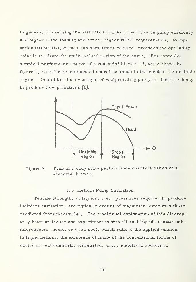
In general, increasing the stability involves a reduction in pump efficiency
and higher blade loading and hence, higher NPSH requirements. Pumps
with unstable H-Q curves can sometimes be used, provided the operating
point is far from the multi- valued region of the curve. For example,
a typical performance curve of a vaneaxial blower [11, 23] is shown in
figure 3 , with the recommended operating range to the right of the unstable
region. One of the disadvantages of reciprocating pumps is their tendency
to produce flow pulsations [6],
A
mInput Power
\Head
\« Unstable
tRegion
Stable
Region
Figure 3, Typical steady state performance characteristics of a
vaneaxial blower.
2. 5 Helium Pump Cavitation
Tensile strengths of liquids, i. e. ,pressures required to produce
incipient cavitation, are typically orders of magnitude lower than those
predicted from theory [24], The traditional explanation of this discrep-
ancy between theory and experiment is that all real liquids contain sub-
microscopic nuclei or weak spots which relieve the applied tension.
In liquid helium, the existence of many of the conventional forms of
nuclei are automatically eliminated, e. g. , stabilized pockets of
12

dissolved gas. Therefore, it was originally thought that it might be
relatively difficult to induce cavitation in liquid helium. This, however,
was not the case, as various researchers using different techniques
3 2found that extremely small pressure drops (of the order of 10 dynes /cm
)
were sufficient to cavitate helium [2 5]. At these incipient pressures, the
observation of visible cavitation [49] coincides with audible cavitation noise
in LHel (T > T )generated from collapsing cavities, whereas in LHe II
A.
(T <T ) only audible noise is detectable. The generation of visible cavi-A.
tation in LHe II is made difficult by the efficient heat transfer mechanism,
internal convection. As mentioned earlier, the small vapor formations
which occur at incipience have an insignificant effect on pump perform-
ance. Incipient cavitation is generated at local low pressure regions
along the surface of the impeller vanes, usually at the suction side of
the vanes close to the leading edge. To minimize cavitation effects, the
fluid should pass through the vanes with minimum disturbance, i. e.,
with zero angle of incidence.
As the pump speed is increased or the NPSH is reduced, cavita-
tion continues to progress. Eventually, a point is reached where the
pump passage ways become partially blocked with vapor resulting in a
drop- off in the head. Pumps especially designed with an inducer stage
(high suction specific speed pumps) can handle fluids which contain
relatively large volume fractions of vapor without surging, damage, or
head drop-off. An inducer is an axial flow impeller having a few long
vanes rather than many short ones. In effect, the fluid residence time
is relatively high, giving vapor formations time to recondense, leaving
sufficient vane surface to impart the required head rise to the liquid
before it enters the main stage impeller.
13

Cavitation data, obtained with a single pump operating in several
different liquids with widely differing fluid properties, have been used
to determine the relative importance of the fluid properties. One
parameter which only qualitatively describes the ability of the fluid
to block the flow passages in a given pump is the density ratio p /p [22],t v
Values of this ratio, computed for several liquids, are summarized in
table 1. Low values of p„/p indicate that blockage effects will be lessI v
severe.
Table 1. Summary of values of the saturated density ratio
p /p at the NBP for several fluids.
V
Fluid
Water 1603
L°2 256
LN2
175
LH2
53
LHe 8
Extrapolation of non-cavitating pump performance from fluid to
fluid and from pump to pump is reasonably well advanced. However,
predicting pump cavitation performance is still not well understood
and is a matter of concern for the designer of high suction specific
speed pumps. The ultimate goal is to be able to predict the cavitation
performance, H = f (NPSH), solely from knowledge of the pump geometry
and the fluid properties at the inlet. The predictive method developed by
Ruggeri, Moore, and Gelder [21] allows the cavitation performance of
a particular helium pump to be accurately determined, provided suf-
ficient cavitation data has been taken on the same pump operating in
another fluid, e. g. ,liquid nitrogen. Unfortunately, there are no LHe
14

cavitation data to verify the extrapolation of this predictive method
to LHe. Figure 4 shows the predicted helium cavitation performance
of a high suction specific speed, centrifugal pump using data obtained
in liquid hydrogen [21], The predicted helium curve shows that block-
age effects occur at much lower values of NPSH than those for liquid
hydrogen, i. e. , at a value of the ratio of head rise coefficients of 0, 9
(equivalent to a head drop-off of 10 percent) the pump in helium requires
only about 6 meters of NPSH compared to 29 for hydrogen. This result
is of practical importance in that for certain applications, pumps of
high N (which tend to be expensive) may not be necessary fors , cav
satisfactory operation in liquid helium.
The orientation of a submerged He-pump can influence its suction
performance. For maximum NPSH the pump should be mounted verti-
cally with the inlet near the lowest point in the dewar. When a pump
is mounted horizontally a short distance below the liquid level, vapor
filled vortices might be drawn into the pump when the liquid is sucked
downward. This could destroy the pump performance. If the pump
must be mounted horizontally, a 90 degree elbow section, with the inlet
facing the dewar bottom, provides a much better inlet condition [19].
In LHe II, pump cavitation is not anticipated to be a problem
because the high effective thermal conductivity of the liquid makes it
difficult for cavities to grow to visible size [25],
15


2. 6 Pump Efficiency
In a helium pump, inefficiencies are not only expensive in the
additional power required but also produce costly losses of fluid. This
is especially true with liquid helium because of its extremely low latent
heat of vaporization. The economic situation will dictate the need for
gas recovery systems. An analysis by Jacobs [26] of pump losses
involved in the transfer of liquid helium shows that for high discharge
to inlet pressure ratios, P^/P^,large quantities of helium can be
wasted, even though the pump may be highly efficient. The limitation
of the present survey to relatively low head pumps is consistent with
this analysis. Large diameter transmission lines tend to minimize
P /P . If the fluid pumped is supercritical helium, the thermal effects
caused by pump inefficiency can produce relatively large increases in
fluid temperature and hence decreases in the density. The importance
of pump efficiency in a particular system also depends on whether the
pump is to operate continuously or intermittently and whether the motor
is submerged or not.
When the motor is submerged (location b, figure 1) the losses
are (1-71 ), where T| = Tl Tl , and T] and T| are the pump and motort t m m
efficiencies, respectively. Little information is available on the per-
formance characteristics of cryogenic motors. Efficiencies of small
induction motors are typically higher (by about 10 percent) at cryogenic
temperatures than at room temperature but they decrease with motor
size [8]. By using long conduction paths, the heat leak through the
motor electrical leads can be made small. The main attractions of a
submersible motor close-coupled to the pump are compactness, elimina-
tion of a rotating seal, elimination of heat leak down the shaft, and mini-
mal mechanical problems due to the short shaft. These features are
17
favorable for flight type systems. A superconducting motor, submerged
in liquid helium, might be used to drive a liquid helium circulating pump.
Small, superconducting motors have successfully been operated at speeds
up to 1200 rpm with all parts flooded with liquid helium [27]. However,
the performance characteristics of these motors are not reported. Since
superconducting motors are still in the development stage, their relia-
bility may be poor.
For a pump operated with a room-temperature motor (location a),
the only work which does not reach the pump is that dissipated by the
shaft motion in the fluid and bearing friction. The amount of heat gen-
erated will depend on the surface speed and the contact area. Compared
to the shaft work and the heat leak into the cryostat these friction losses
are small and can usually be neglected. This configuration requires a
relatively long pump shaft passing through a rotating seal to the motor.
A tubular shaft made of stainless steel rather than a solid shaft greatly
reduces the heat leak from the room-temperature motor to the pump.
Several commercially available room-temperature, rotary seals are
currently available. These seals, guaranteed to be leak tight for vac-
uum systems, are designed for speeds up to 10, 000 rpm.
Since the density and viscosity of liquid helium is low, it can
readily pass through small apertures. Because of this, a piston type
pump would need close-fitting parts which in turn might produce high
friction losses.
Some efficiency design criteria have evolved from the large
accumulation of pump data. A few of these criteria are:
1) Pump efficiency depends on the specific speed;
e. g. , the highest centrifugal pump efficiencies
occur in the specific speed range of 1500 to 2000.
18
2) A wide centrifugal type impeller of small diameter
gives higher efficiencies than a larger thinner impeller;
the latter shape, however, gives a steeper, more stable
H - Q curve.
3) Pump efficiency increases with Reynolds Number, Re.
4At Re > 2 x 10 , pump efficiencies are independent of Re.
4) The efficiency of axial flow pumps is more nearly constant
with variations in head rise, compared to other pump types.
5) A vane discharge angle, (3 , of about 22-1/2 degrees should
be used, if possible.
6) All parts which take part in the generation of head should
be streamlined. All fluid passages should be smoothed
by polishing or with special coatings.
2„ 7 Reliability
The reliability of a helium pump depends primarily on the bearing
life and the operation of the motor. Hydrodynamic bearings should be
avoided because of complexity. Since the small surface contact area
of a radial-contact ball bearing will result in a minimum of heat gen-
eration, they are recommended for impeller pumps. At helium tempera
tures, bearing heating is not expected to be a problem. Modern cryo-
genic ball bearings use a glass-reinforced PTFE retainer. The life
of these bearings with small loads over wide ranges of speed are of the
order of thousands of hours. Submerged centrifugal pumps usually
require that one or more bearings are lubricated by the helium, which
has poor lubricating qualities. Redmond and Bott [28] have used a
retainer impregnated with MoS^ to provide lubrication of the balls
(440 C stainless steel) at helium temperatures. If the ball bearings
are prevented from skidding during rapid acceleration from rest,
19

intermittent operation should not effect the bearing life. Contaminates,
such as ice crystals, can be abrasive and thus a threat to long bearing
life and pump reliability.
Since positive displacement type pumps (gear pumps) have
relatively high weight and wear rates [8], their reliability may be
poor.
Polyphase cryogenic induction motors are reliable because there
are no brushes to wear out. However, D. C. brush type motors have
been successfully operated in cryogenic liquids and gases [8], At
1 to 10 watts design input, the motor reliability is lower because of
low torque and interference problems due to possible contamination in the
bearings. To minimize the starting torque requirements, stable
pumps of low specific speed should be started with the discharge valve
closed. The design and construction details of small induction motors
which operate at helium temperatures are given by Redmond and Bott [28].
These motors have operated for hundreds of hours at temperatures down
to 20 K and therefore are quite reliable.
3. Survey Results
3. 1 Literature Review
An extensive review of the available literature has been made to
assist in assessing the state of the art of helium pumping. Although no
complete cryogenic helium performance characteristics are reported,
supercritical helium has been pumped in several closed loop heat trans-
fer systems and liquid helium has been pumped by a centrifugal pump
and by a small reciprocating pump. Attempts to pump liquid helium
below the X-point with a mechanical pump have not been reported.
20

Johnston (1946 - 1947)
In his pioneering work on pumping liquid cryogens, Johnston
[29, 30 ] tested a variety of commercially available pumps— gear pumps,
diaphragm pumps, and centrifugal pumps. Although he did not do any
pumping of helium, many of the problems he experienced with these
commercial pumps operating in LN^ should be applicable to the heuristic
problem of using an off-the-shelf water pump in liquid helium. Of the
above pump types tested, it was concluded by Johnston that a centrifugal
pump, with a straight-vane impeller and carefully designed diffusion
passages for outflow, worked the best.
Gottzmann (1959)
In his study of high-pressure liquid hydrogen and liquid helium
pumps, Gottzmann [31] used a single stage, centrifugal forepump to
provide adequate head to the liquid entering a reciprocating, high-
pressure pump. This work is the first reported attempt to pump
liquid helium and was apparently quite successful. The centrifugal
pump was driven by a close-coupled, canned electric motor which was
immersed in the liquid helium. The head rise and the NPSH required
at the design conditions (presumably for water) was 24 m (80 ft) and
0. 61 m (2 ft), respectively. The forepump apparently worked trouble-
free during the course of the tests. Unfortunately, neither the details
of the centrifugal pump nor its helium performance data were reported.
Yonemitsu and Okada (1964)
The authors £32] describe the use of a plunger type pump to trans-
fer liquid nitrogen to cool an infrared detector. The reciprocating
plunger is driven by a room-temperature crank mechanism via a
stainless steel connecting rod which passes through a warm O-ring
21

seal. The pump output is controlled by varying the speed of a room
temperature motor 0 The piston and cylinder are made from a hard-
surface material with a very fine finish in order to use the liquid as
a lubricant. Details of the pump dimensions and performance char-
acteristics are not reported,
Parrel and Schoch (1965)
A small liquid helium superconducting pump capable of trans
-
-6 3ferring 6. 94 x 10 m /s (0. 11 gpm) with a discharge head of 0. 92 m
-6 3(3 ft) and 3. 3 x 10 m /s (0. 053 gpm) at a 1.83 m (6 ft) head is
reported by Barrel and Schoch [33]. The pump is 7/8 inches in
diameter and 2 inches long. A superconducting niobium piston,
suspended by a thin-wall nickel bellows, is forced to oscillate at a
resonant frequency of 120 Hz by 60 cycle current flowing through a
superconducting coil, located below the piston. The flow rate could
be adjusted by varying the amplitude of the coil current. The mass
of the piston (armature) and the bellows spring constant were selected
to produce resonance at this frequency. When the piston moves upward,
hydrodynamic forces cause the suction valve to close and the discharge
valve to open, forcing liquid through the outlet tube. These valves are
disk-type made of 0. 015 inch thick nylon. In reciprocating pumps, the
geometry and spring design of disk-type inlet valves can affect the cavi-
tation performance.
The reliability of this pump depends primarily on the life of the
bellows, which is not well known. The leakage rate past the valves and
hence the volumetric efficiency is not reported. These could be severe
problems in pumps of larger size. Considerably more testing of this
type of pump is needed before a true evaluation of its merits can be
given.
22

Kolm, Leupold, and Hay (1965)
A small reciprocating pump using a metal bellows has been
designed for circulation of supercritical helium by Kolm, et al. [34].
The pump armature is driven by a superconducting coil surrounding the
outside of the pump housing. Two gravity-loaded ball valves provided
unidirectional flow. Both the bellows displacement and cycling rate
could be continuously controlled. A second reciprocating pump which
used a double-acting stainless steel piston was also made by the authors
for the circulation of supercritical helium. When operating at two6 3
strokes /sec, this second pump produced a flow rate of 6. 4x10 m/s(0. 1 gpm). The complete performance characteristics of these two
pumps were not reported. The use of ball check valves in liquid have
been known to cause cavitation difficulties [29].
Caine and Pradhan (1967)
The design criteria of small, submersible de stratification fans
(axial flow pumps) are described by Caine and Pradhan [8], These fans
are designed for liquid and gaseous hydrogen but should work approxi-
mately the same in helium. A typical fan of 48 mm (1. 9 inch) tip
diameter rotating at 3500 rpm produces a flow of 35 gpm and a head
of about 0. 67 m (2. 2 ft). Typical characteristic curves and model
data at the b. e. p. are given for a 0. 3m (1 ft) diameter axial flow pump,
with N = 16, 000. These axial flow fans are commercially available,s
Wright (1967)
The construction and performance of a double -entry centrifugal
pump for transferring LN^ are discussed [22], Quiet and very reliable
performance are reported. At the time this paper was published, the
pump was commercially available. The author mentions that the pump
should work in helium above the X-point; however, no helium tests were
23

performed. The outside diameter of the pump is 48 mm. It is verti-
cally mounted and driven by a warm, 10-watt, electrical motor with
a long, stainless steel shaft. The impeller (plastic or metal) has six
unshrouded backward-curved blades. Two bearings are used: 1) to
support the impeller, and 2) to prevent whipping of the shaft. The3
estimated bearing life is 10 hours. The fluid enters the pump from
both the top and bottom of the pump casing through 10 mm diameter
holes. The driving shaft also enters through the top hole. The use of
an unshrouded, double entry design gives low impeller bearing loads
and overcomes problems of vapor accumulation (i. e. , gravity forces
allow vapor formations in the eye of the pump to escape vertically
through the top hole in the casing). Table 2 is a summary of the
reported performance obtained in LN^ .
Table 2. LN pump performance reported by Wright
N Q Head
(rpm) (m3/s) (gpm) (m) (ft)
2, 850 0. 0 0. 0 1. 73 5.7
3. 3 x 10" 50. 53 0. 0 0. 0
10, 000 0. 0 0. 0 15. 7 51. 5
83. 5 x 10' 513. 2 0. 0 0. 0
Mulder (1968)
A small electrically driven centrifugal pump (N = 700) was useds
by Mulder [3 5] to circulate high pressure supercritical helium (25 atm).
A stainless steel shaft was used to minimize the heat leak from the
room-temperature motor to the pump. The centrifugal impeller, con-
sisting of 12 radial blades, was run at speeds ranging from 12,000 to
18, 000 rpm. The performance characteristics of the pump are given;
24
however, these were presumably not measured in cryogenic helium.
The pump appears to be stable and has a maximum efficiency of 50
percent. At the b. e. p. the head and flow are about 77 m and-4 34x10 m /s (6. 4 gpm). Operating problems (if any) are not discussed
by Mulder. A model of this pump is not commercially available [2],
Morpurgo (1968)
A double action piston pump was designed and used by Morpurgo
[ 1 ] to force cool a superconducting system with supercritical helium.
The pump is driven by a warm electrical motor and a long, thin rod and
crank mechanism. The pump speed is variable from 5 to 200 turns per
minute. The maximum speed corresponds to a helium flow of about-4 3
1. 17 x 10 m /s (1. 9 gpm) at a low differential pressure.
Sixsmith and Giarratano (1970)
The authors [2] describe a miniature centrifugal pump, designed2
to circulate supercritical helium at high pressures (10 MN/m or 100 atm).
Head- capacity data, obtained with cold nitrogen gas at several speeds,
are included. The pump is stable at all speeds tested and at 30, 000 rpm
produces a maximum head rise at shut-off of about 67 m and a maximum-4 3
flow of 2. 5 x 10 m /s (4 gpm). This pump is driven by a room tem-
perature motor connected by a stainless steel shaft, about 140 mm in
length. The centrifugal impeller (25. 4 mm diameter) is doubly- shrouded
and is composed of 18 backward curving vanes. In order to eliminate
surging at low flow rates, the pump was made without a diffuse r. It has
several hundred operating hours with helium at temperatures from 4. 2
to 30 K. However, it is not presently instrumented for the acquisition
of helium performance data. Fabrication of this pump is relatively diffi-
cult and therefore expensive.
25

There are two features of this pump which might give rise to
poor cavitation performance in liquid helium:
1) The inlet section (as designed) has several sharp corners
which could induce premature cavitation.
2) The high number of vanes gives relatively small flow areas.
Therefore, blockage of the flow passage ways due to cavitation might
be considerable.
Wagner (1970)
A small electrically driven pump and stirring unit for use at
2temperatures from 4 K to 350 K and pressures up to 10 MN/m is
described [36]. The unit was designed for circulation of gas-liquid
systems for phase equilibrium experiments. A small cryogenic D„ C.
motor was developed especially for this work. The liquid phase is
sucked by an axial flow impeller and pumped into a mixing chamber.
The gas phase is driven by a six-vane, centrifugal impeller. Both
impellers, connected to the same shaft, are driven by the motor. At
3000 rpm (0. 04 watt motor input) the pump produces a flow rate of
- 6 35x10 m / s (0. 08 gpm). It has been operated in nitrogen and helium
for continuous periods of 80 and 4 hours, respectively. The estimated
life of the ball bearings is 2500 hrs.
Heron and Cairns (1970)
A small centrifugal pump, used to circulate supercritical helium
(T ^ 4. 5 K) in a closed loop heat transfer experimental system, is
described [ 3 ]. The pump performed trouble-free throughout the experi-
ments. However, the authors did experience some problems with ther-
mal oscillation in the flow loop. The complete head-capacity character-
istics could not be obtained because of poor throttling characteristics
26

of a bypass valve. The impeller, 30 mm in diameter, has 12 straight
radial vanes, 4 mm wide. The pump is driven at 18, 000 rpm by a
3-phase room-temperature motor connected to a 60 mm long stainless
steel shaft. The power into the pump was 24 watts. The maximum5 2
flow of supercritical helium at 4 x 10 N/m (4 atm) at 6. 5 K was-5 3
estimated to be 7x10 m /s(l.l gpm).
Mark and Pierce (1971)
The authors [37] have used axial flow fans (air blowers) to cir-
culate liquid hydrogen through hydrogen targets. Prior to their opera-
tion in LH^, these fans are run for a short time in LHe. The blowers
are similar to those described by Caine and Pradhan [8] but are
operated at speeds far below the design speed and are therefore very
inefficient. These fans also have been arranged in series for higher
output head. Although the fans are adequate, a small centrifugal pump
better suited to the work has been developed and tested in liquid nitrogen.
At the time of the report, work was in progress to build hardware to
test the pump in hydrogen and helium. The pump should have the per-
formance given in table 3.
Table 3. Estimated performance of heliumcentrifugal pump reported by Mark and Pierce.
N Q Head
(rpm) (m3/s) (gpm) (m) (ft)
3,400 3. 3 x 10" 50. 5 3 1. 5 4. 9
10, 000 9. 7 x 10" 51. 56 13 42
Specific details of this centrifugal pump are not reported but it is
believed to be similar to Sixsmith and Giarratano's [2].
27

Summary:
Although much of the performance data is sketchy, the literature
review shows that supercritical helium and liquid helium above the
X-point can effectively be transferred by mechanical pumps. The impel-
ler pumps are by far the most popular and appear to offer distinct advan-
tages of stability, wide ranges of operation, and ease of control. Such
pumps are ideally suited for low head high flow situations. Reciprocating
pumps on the other hand offer no obvious advantages (other than their size
and shape) for producing low heads and high flows. Unfortunately, most
of the pumps described are made for specific applications, are not com-
mercially available, and are expensive to make. Since the same types
of pumps are effective in LHe as well as supercritical helium, a single
machine should be able to pump both phases of helium, provided cavita-
tion effects are negligible. The cavitation effects on a pump operating
in liquid helium are not presently known and pumping LHe II using a
mechanical pump has apparently, here-to-fore, never been attempted.
The author has recently pumped LHe II (T = 1.9 K) with a small centrifu-
gal pump with no apparent difficulties. The results of these tests are
presented in part 4 of this report.
In future helium experiments which require the use of a pump,
the installation of additional instrumentation to determine the perform-
ance characteristics would be of considerable help in the development
of optimum helium pumps.3
3. 2 Commercially Available Pumps
As noted from the review of the literature, pumps for helium
service are not readily available. In this section the results of
The pumps referred to in this section are coded. A copy of the code
list may be obtained by writing to Dr. Edward L. Brady, Associate
Director for Information Programs, Institute for Basic Standards,
National Bureau of Standards, Washington, D. C. 20234
28

personal communications with various pump manufacturers are reported.
It was hoped that suitable helium pumps might only require slight modi-
fications from the manufacturers standard line of pumps for which a
complete set of water performance characteristics are usually available,,
The effort was concentrated on the established cryogenic pump manu-
facturers. However, many manufacturers of other types of pumps were
also contacted. Most of the commercially available cryogenic pumps are
relatively large, powerful impeller pumps and not designed for sub-
mersion or for operation at low flow rates. The helium losses for these
pumps would be considerable. Many of the pump manufacturers con-
tacted by letter did not respond while others thought that pumping helium
would be impossible.
Pump A
Pumps of this basic type are made for LN^ service. It is a
single stage centrifugal pump. For helium service, the pump
would be vacuum jacketed and made of stainless steel.
A complete predicted performance map is available. According to the
- 3 3manufacturer, it produces 6. 3 x 10 m /s (100 gpm) with a total dynam-
ic head of 159 m (520 ft) and has an efficiency of 60 percent. The NPSH
at these conditions is 3 m (10 ft). It is driven at 7200 rpm by a room-
temperature, 2. 2 kW (3 hp) motor, controlled by a variable frequency
power supply. The price of the pump (including motor and power supply)
is approximately $11, 000.
Pump B
This submersible pump is part of an automatic LN level control-5 3
system. It will discharge approximately 4„ 9 x 10 m /s (0 o 78 gpm)
against a head of 1. 5 m (5 ft). The maximum diameter of the pump is
about 50 mm. It is driven by an electric motor (10 watts) and costs
approximately $400.
29
Pump C
This is a small, centrifugal pump designed for operation in room-
temperature fluids. This model is made of 316 stainless
steel and would require modifications of the bearings to operate
in helium. It is driven by an electric motor at 10,000 rpm via
a ceramic magnetic -coupling. Use of a magnetic coupling eliminates
the need for a rotating seal. Wagner [36] found that at temperatures
less than 80 K, some ceramic magnets lose much of their residual
magnetism and thus their ability to transmit torque. An investigation
would be needed to see if this is the case with pump C. Stray magnetic
fields from the superconducting system might also affect this coupling
if not shielded. A solution to these problems is to directly couple a
room-temperature motor to the pump and use a rotating seal or use
a close -coupled submersible motor. The total length of the motor and
pump is 178 mm and the maximum width is 88 mm. The reported
performance (head-capacity curve) is stable and produces about 12 m-4 3
(40 ft) head at zero flow and 4. 4x10 m/s(7 gpm) at zero head. The
pump and motor sells for about $100.
Pump D
This is an all-PTFE pump which uses a nutating (360°
oscillating) disk to produce pumping . The pump is sealed with a
bellows and can be driven with a 37 watt (1/20 hp) motor. Although this
pump is interesting and novel, materials tend to become brittle at helium
temperatures which might give rise to unsatisfactory performance at
-5 3these temperatures. It produces 6. 7 x 10 m /s (1 gpm) with a head
of about 10 meters (30 ft). Self-lubrication of the PTFE reduces friction
and wear of parts. The pump has been used successfully with a wide
variety of fluids; however, operation in cryogenic liquids is not reported.
Because of the low viscosity of helium, leakage in this pump might be
considerable. Certainly, more testing is needed before it can be
accepted as a useful cryogenic pump.
30

Pump E
This is a small centrifugal pump designed for room-5 3
temperature liquids. It produces about 8. 4 x 10 m /s (1. 25 gpm)
at a head of 1 3 m (44 ft). Its appearance is quite similar to pump C and
is magnetically coupled to the motor in order to eliminate a dynamic
seal. Operation of this pump in helium would require modifications
similar to those recommended for pump C.
Pump F
These submersible pumps are of low weight and small
size and are designed for blowing air. Consequently they produce high
flow at relatively low head. Driven by close coupled, submersible
motors modified for cryogenic use, these pumps have been used at
reduced speeds in liquid hydrogen experiments to provide forced circu-
lation. However, at these low speeds, the efficiencies are low. They
have also been run for short times in liquid helium. The head- capacity
curve shows an unstable characteristic at the lower flow rates, see
figure 3 Q These motor-pumps (modified for cryogenic use) cost a few
hundred dollars, depending on the size.
Pump G
This is a submersible 100 mm (4 inch) centrifugal pump
made for pumping liquid propane. Rotating at 3560 rpm,-3 3
it develops a head of 43 m (140 ft) at a flow of 1. 3 x 10 m /s (20 gpm).
The motor should draw about 225 watts (1/3 hp) at the above output con-
dition when operating submerged in liquid helium. However, this motor
has never been operated at helium temperature. This submersible pump
(including motor) costs about $2600.
31

Pump H
This is a centrifugal, cryogenic pump driven by a room-
temperature electric motor. At maximum efficiency, 44 percent,-3 3
and a speed of 1450 rpm, it will produce 5 x 10 m / s (75 gpm) with
30 m (100 ft) of head. The pump, made of 304 stainless steel, comes
with flanges at the inlet and outlet for mounting in a horizontal position,
for example, in a pipe line. The manufacturer claims that vapor binding
is prevented by having a vertical top suction. Vapor binding is inter-
preted as vapor accumulation around the impeller. The cavitation tests
of DiStefano and Caine [19] showed this configuration to be least desira-
ble in a submerged pump. The pump (without motor) is priced at about
$3000.
Pump I
This pump is a submersible, LO pump used for NASA space
applications. The internal parts of the motor do not come in contact
with the oxygen. The motor, when corrected for the specific gravity
of liquid helium, should draw about 66 watts (0. 09 hp). At the design-3 3
speed, 11,000 rpm, it produces a flow of 2 x 10 m /s (30 gpm) with
a head of 10 m (30. 4 ft). Because of the many special features incor-
porated for space flight, this pump would be relatively expensive.
Pump J
This is a small stainless steel centrifugal pump designed
for operation in liquids at room-temperature (and higher). It is
driven at 3100 rpm by a canned, 50 watt (1/15 hp) motor and is
similar to pump C. Its head- capacity curve (which is stable) shows
that the pump will produce about 3. 5 m of head at shut -off and at full
-3 3capacity, 1. 1 x 10 m /s (16 gpm), about 1. 2 meters. The water
32

NPSH required at full capacity is about 5 m (15 ft). The base price
of the pump and motor is less than $100. Modifications similar to
those mentioned earlier for pump C would be needed before this pump
could be used in helium.
Pump K
Submersible axial flow pumps described by Caine and Pradhan
[8] are commercially available. These are high flow - low head
machines of proven reliability in various cryogenic environments.
33

4. Pump Tests
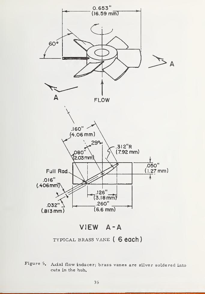
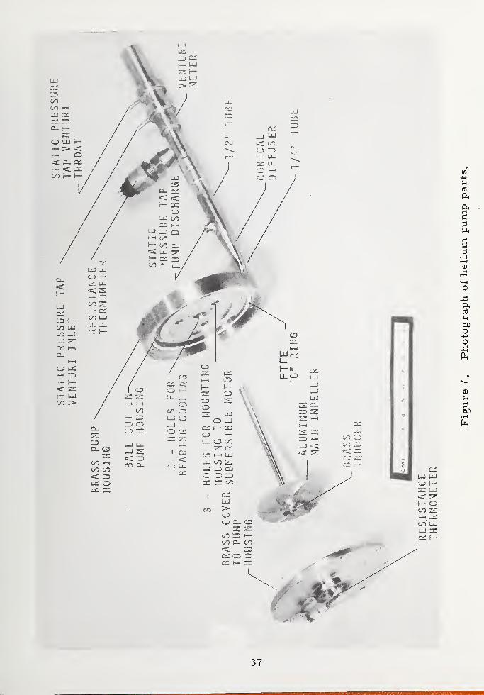
4. 1 Description of the Tested Pump
The test pump, which was designed and fabricated in a few week's
time, consists of an axial flow inducer, a centrifugal impeller, and a
two-part pump housing which includes a vaneless diffuser. These parts
are shown in detail in figures 5, 6, and 7, respectively. Figure 8 is
an assembly drawing of these parts. The pump was designed to meet
the following specifications in liquid helium at 4. 2 K with a rotative
speed of 628. 3 rad/s (6000 rpm):-4 3
a) capacity = 2, 52 x 10 m /s (4 gal/min)
b) total dynamic head = 15.2 m (50 ft)
c) efficiency > 50 percent
d) stable operation from shut-off to full flow capacity
e) cavitation free operation with NPSH ^ 0. 305 m (1 ft).
The inlet and discharge velocity triangles, based on the above design
criteria, are shown in figure 9. The selection of |3 =60° was based
on consideration of the desired steepness of the head-capacity curve and
the required output for a given speed and impeller diameter. The choice
of 3^ is important, since all the non-cavitating design constants depend
on this value. To meet the stability requirement, the centrifugal impeller
was made with a low number of backward curving vanes (six) and a
relatively high breadth ratio, D^/B^ . The centrifugal impeller and
inducer vanes were machined with a numerically controlled mill. This
allowed duplicate (or scaled) pieces to be made quickly at low cost.
These rotating parts were statically balanced before final assembly. The
clearances in the pump had to account for differential expansion, AL/L,
between brass and aluminum over the temperature range of 1. 8 to 300 K.
_4The magnitude of this difference is about 3x10 m/m.
The above pump parts were designed to mate to an existing 3-phase
submersible, cryogenic induction motor rated at 35 watts, as shown
34
0.653"(16.59 mmT
VIEW A-A
TYPICAL BRASS VANE ( 6 eOCh )
Figure 5. Axial flow inducer; brass vanes are silver soldered intocuts in the hub.
35

1.9652"(49.9! mm!
u!" (19.05mm)
.260(
(6.6 mm).12" R(3.05 mm)
B2
.035"
(.89 mm)
.031" .134'
(.79 mm) (3.40 mm)B,
Figure 6. Centrifugal impeller for helium pump, 6061 -T6 aluminum,anodized finish.
36
u
a
O
uGfl
O
o
Oh
OX)
37

Stainless Steel Tubing
Helical CompressionSpring
^6-32 NC Self -locking Nut
Low - temperatureBearings with Glass
impregnated, PTFE Retainer
Submersible 3-PhaseInduction Motor,
400 Hz, 208 VAC L-L120 VAC L-NPower max 3 5 W
3 Holes, .088"dia. (2.24 mm)for Bearing Cooling
Groove for
PTFE O-Ring
035'
(89 mm )
(95.25 mm)
Figure 8. Assembly drawing of helium pump and submersible motor.
38

,= 20.1°
u, = r u) = 397 cm/s
a. Inlet velocity triangle at mean effective inducer diameter,D = 12. 6 mm (0. 497 in ); n = 628 rad/s (6000 rpm);m _4 3Q = 0. + Q = 3. 1.6 x 10 m /s; zero prerotation.
u, =1 568 cm/s T
ft
b. Velocity triangle at centrifugal impeller discharge,;
n = 628 rad/s (6000 rpm); Q = Q + Q = 3, I6x 10"'4 m3 /s.
Figure 9. Inlet and discharge velocity triangles based on the designcriteria.
39

in figure 8. The motor speed is controlled with a three phase, variable
frequency (300 - 500 H ), variable voltage (0 - 120 V L-N) power supply.
This motor, originally made for NASA to drive miniature de stratification
fans [28, 8], is designed to operate over a wide range of temperatures
(4 K < T < 300 K), and since it has been operated for hundreds of hours
in air, gaseous oxygen, liquid nitrogen (LN^) „ and liquid hydrogen
(LH^), is quite reliable. In the present studies, the motor efficiency,
when running submerged in helium is not accurately known but is esti-
mated at 35 to 50 percent [8], Efficiencies of small cryogenic induction
motors typically decrease with the size of the motor.
4. 2 Test Loop and Instrumentation
The pump test loop and instrumentation are schematically shown
in figure 10. The vertically mounted pump is suspended a few centi-
meters from the bottom of a 1. 22 m deep, stainless steel, cylindrical
dewar by two stainless steel support tubes. The electrical leads for
the submersible motor, liquid level meter, speed sensor, and resistance
thermometers are fed through these support tubes. The fluid is pumped
vertically upward through a venturi flow meter, then passes through a
3/8-inch cryogenic throttling valve (flow coefficient = 1. 1) and is finally
discharged at low velocities through a conical diffuser. The leak rate
of the throttling valve when closed and pressurized with helium gas was
checked in liquid nitrogen by observing extraneous bubbles. Since at
pressures twice those expected in the pump tests, only a few bubbles
were occasionally emitted through the stem, the valve was considered
to be sufficiently tight to determine the head rise of the pump at zero
flow.
The pump speed, n, is determined from the frequency of an
alternating voltage, generated from an electro-magnetic pickup, whose
magnetic field is periodically perturbed by a 20-tooth ferrous gear.
This gear is rigidly attached to the top of the pump shaft. The frequency
is measured by a counter.J /in

Pressure Lines
He Environment
OSCILLATOR
100 Hz
CAPACITANCE
BRIDGE
LIQUID
LEVEL
20 fjk
CONSTANTCURRENT
SUPPLY
SWITCH
Ri R2 R3
RESISTANCE
THERMOMETER CIRCUIT
FREQUENCY
COUNTERSHAFT
3 PHASE, VAIIAILE
VOLTAGE, VARIABLE
FREQUENCY POWER
SUPPLY
POLYPHASE
WATT
METER
SPEED
MOTOR
POWER
5.7 cm
Centrifugal impeller
Axial flow inducer
,aP.
Extended valve stem
Support tubes
Discharge control valve
Venturi meter
Concentric cylinder
capacitance level gage
R2
resistance thermometer
at venturi inlet
Conical diffuser
Magnetic speed sensor
20-Tooth, steel spur gear
R3 resistance thermometer
in bearing coolant passage
3-Phase induction motor
Pi
Stagnation pressure tap
at pump inlet
R1 resistance thermometer
at pump inlet
Figure 10. Schematic diagram of He-pump test loop and instrumentation.
41 IB- 103798~|

The fluid discharged from the diffuser mixes the fluid surrounding
the pump and helps maintain a constant bath temperature, determined
by the vapor pressure above the liquid surface. Consequently, when
pumping liquid helium, the height of liquid above the pump inlet is equal
to the NPSH. A calibrated capacitance level gage, shown in figure 10,
is used to measure the liquid level in the dewar and hence the NPSH at
the pump inlet. The sensing capacitor, one leg of the capacitance
bridge, consists of two concentric stainless steel tubes running the full
length of the dewar. Only the very top and bottom of the outer tube are
open to the bath. The bridge output voltage, measured with a DVM, was
somewhat noisy, varying as much as 2. 4 percent during a measurement
interval of 1 minute. The precision of the liquid level measurements,
as typified by the overall standard deviation of the calibration data, is
40 mm.
The fluid temperatures at the pump and venturi inlet,T^ and
T,respectively, are measured with calibrated, 1/8 watt carbon
resistors, R, and R . The resistor R„ is positioned halfway inside12 2 r 7
the discharge tube and tightly sealed from the helium bath. A third
resistor, R , located inside the motor and near the top, is used to
detect any significant temperature increase due to possible bearing
heating; none was observed. These thermometers, powered by a constant
D. C. current of 20 \s A ± 0. 01 |j,A, were calibrated in place against the
saturation temperature of LHe (in equilibrium with its vapor) over the
range 1, 75 K<T< 5, 2K. To extend the calibration range to 20 K, the
three thermometers were immersed in liquid hydrogen. The voltage
drops across R^, R , and R^ were measured on the same DVM mentioned
earlier. Steady background thermal emf 1 s were subtracted out by taking
two readings, one with reversed current. During the calibration, the
42

system pressure, maintained constant with, a manostat to within
2930 N/m (7 mmHg), was measured by directly observing one of three
manometers, depending on the pressure range. Systematic errors in
the T-R calibration data can occur due to thermal stratification in the
fluid and slight changes in resistance with time. Errors in temperature
can be as high as 2 K in some liquid helium systems with severe strati-
fication. Past experience using carbon resistor thermometers in helium
indicate that they are reproducible to within 0. 010 K over a period of a
few months.
Over the temperature range 1. 7 K < T < 20 K the calibration data
fit a logarithmic expansion of the form
6
£n T = C + Y C. ((nR)1
,
o . , ii = i
where C , C , . . . C. are constants. With measurements of R ,
o 1 6 1
R , and R , this function is used to compute T , T , and T in the
analysis of pump performance. With these curves, the total rms error
of the calibration data is 0. 86 percent, 0. 55 percent, and 0. 44 percent,
respectively for T^, T^, and .
The differential pressure across the pump,AP , and across theP
venturi , AP , are directly measured with differential, bellows -type,
pressure gages. These measurements are used in the calculations of
the total dynamic head and the rate of volumetric flow discharged,
respectively. The pump discharge static pressure, P^ , and the ullage
pressure, P , are measured with manometers. These manometeru
measurements are used to check the direct measurements of AP andP
to compute the fluid densities at the pump inlet and discharge. At
system pressures equal to or greater than ambient, the manometer
43

measurements of and P are gauge pressures. With system pres-
sures less than ambient, P is measured with an absolute manometeru
and P is determined from P = P + AP , where P is the sum of2 Z 1 p 1
pressure due to the hydrostatic fluid head above the pump inlet and P
When pumping liquid helium, the unknown location of the liquid
-
vapor interface in the pressure lines is a source of both random and
systematic error in these pressure measurements. This problem can
be eliminated by using vacuum insulated pressure lines with a heater
attached at a known location on the inner lines. This step, which greatly
complicates the system and gives additional heat leak, was not required
in the present work. In the differential pressure measurements, it is
assumed that this interface occurs at the same elevation in each of the
two lines since temperature differences between the different pressure
lines were minimized by wrapping them with copper wire and soldering
them altogether at several points.
Both differential pressure gages, sized for the pump design criteria,
were calibrated over their full range against a differential manometer
filled with distilled, room-temperature water. The precision of the
AP gage (range 0-20 inches of H O) , estimated from the standard
deviation of the calibration data, is about 0. 8 percent of full scale. The
absolute error in AP is estimated to be less than 1. 8 percent at thev
high flow rates and increases to about 8 percent at the lowest recorded
flow rates. Similarily, the precision of the AP gage (range 0-100 incheP
of H O) is 0. 4 percent of full scale. The absolute error in AP is2 p
estimated to be less than 4. 0 percent over the range of AP's typically
produced by the pump. The response time of both AP and AP systemsv p
(i. e. the pressure lines and gages) to sudden changes of differential
pressure in the dewar is less than 5 seconds.
44

In order to accurately measure the ullage pressure, P , in
5 2U
the dewar over the entire range from 0 to 3 x 10 N/m , three mano-
meters were used which covered the following ranges of absolute
pressure:
5 20 < P < 0, 6 x 10 N/m ,
Maximum, estimated error ofu
pressures measured in this
range is 8. 3 percent.
5 20„ 8 < P ^1.4x10 N/m
,Maximum, estimated error of
u
pressures measured in this
range is 0„ 5 percent.
5 5 21.4x10 <P < 3. 0x10 N/m , Maximum, estimated error of
upressures measured in this
range is 0. 1 percent.
Significant thermal-acoustic pressure oscillations were not
observed in any of the pressure gages during the course of these experi-
ments. This is a fortuitous result, since in general, thermal oscillations
and instabilities have been known to be problems of major importance in
helium systems [40], The elimination of such oscillations may partially
be due to the construction of the stainless steel pressure lines, which
typically consist of a length of a small diameter tube (1 0 4 mm i. d. ),
originating from the pressure source, followed by a larger tube
(2. 9 mm i. d. ) which leaves the low temperature environment. The
different sizes of line represent resonant cavities of different volumes.
Therefore, the possibility of system resonance to oscillations of any one
frequency are presumably reduced.
The average 3-phase power into the motor was measured with a
two element, polyphase wattmeter. The power and frequency ranges
of this meter are 0-60 watts and 2 5 to 800 Hz, respectively. The
estimated accuracy of the power measurements is 0. 75 percent.
45

The venturi meter used to measure the helium flow rate is shown
in detail in figure 11. Since the venturi is not calibrated, its dimensions,
which are based on standard forms, had to be machined accurately in
order to use the recommended [41] discharge coefficient, which is a
5function of the tube Reynold's number, Re. When Re > 2 x 10 , the
discharge coefficient is constant and equal to 0. 984. It has been found
experimentally that the discharge coefficient is almost the same for
compressible fluids and incompressible fluids for well designed venturi
meters [17], The internal dimensions of the venturi were obtained by
pouring molds of the inside contours with dental plaster, whose setting
contraction is 0. 05 percent. The external mold dimensions were then
measured with an optical comparator. The errors in fluid density and
in AP both contribute to the total error in the volumetric flow rate,v
estimated to be 4„ 1 percent at the lowest values of flow and 1. 1 percent
at the highest. Flow measurements in LN^ and LH^ have also been
made in previous work, using similar venturi meters [42,43],
4. 3 Results of Pump Test
During a typical (non- cavitating) performance test, the pump,
started with the discharge throttling valve closed, is slowly brought
up to the desired speed, n, which is maintained constant to within
± . 3 percent. The measured head rise across the pump typically4
reaches a steady value within 20 to 30 seconds. This comparatively
long time appears to be associated with the creation and decay of
perturbed temperature distributions in the pressure lines due to
movements of cold fluid into the initially warmer lines. At this
shut-off condition, AP = 0, indicating zero flow through the venturi
meter. There is, however, some flow through the bearing cooling
passages, shown in figure 8. The magnitude of this coolant flow, Q ,
~*! !
—
Similar waiting times were also characteristic of the measured head
rise when the pump was started with the discharge valve fully open.
46

(tutu 8*;
(UJW98 -QlT
47

is not accurately known, but can be estimated from the relationship which
describes orifice flow,
where C is the discharge coefficient, A is the orifice area (11. 8 mm ),
and AP/p is the static head loss across the orifice. At the pump design
speed, Q is estimated to be about 25 percent of the design flow capacity.
When the pump tests were finished, it was concluded that bearing heating
was insignificant and that this forced cooling of the bearings was
unnecessary.
The pump flow capacity, Q, is altered by throttling the discharge
valve. For each valve setting, the static pressure rise, AP , theP
power consumption to the motor, W, and the helium flow rate through
the venturi, are simultaneously measured. In this way, the pump
characteristics, H = f (Q), W = f (Q), and total efficiency = f (Q) are
determined. Data are taken for both increasing and decreasing values
of Q. The total dynamic head, generally defined for steady state
conditions, is
(11)
Z
(12)
1
and is directly related to the power, W^, expended by the pump on
the fluid, where
Wf
= mg (H) . (13)
In the application of (13) to the present study, rh is the rate of mass
flow through the discharge tube, measured by the venturi meter. However,
48

the pump is also expending a certain amount of useful work in pumping
fluid through the bearing cooling passages; e„ g. , at 628 rad/s (6000 rpm)
the magnitude of this rate of work is estimated to be about 0. 8 watts.
This contribution is neglected in calculations of efficiency.
If the fluid is isothermal and incompressible, the integral in
(2) is simply (P - P )/gp. The first two terms in (2) are small com-
pared to the third. Therefore, the percent error involved in calculating
the total dynamic head is approximately the same as the error in
APmeasuring ^-
, which is believed to be less than 5. 3 percent. SinceP
typical measured temperature differences (T - T ) are only a few
hundreths of a degree, the isothermal approximation is valid. However,
the incompressible assumption for pumping helium must be examined
closely. In the present tests, the values of (P - P ) are at the most4 2 . .
1. 5 x 10 N/m (0. 15 atm), and hence, the error in the incompressible
approximation is small when pumping liquid helium. For the tests with
supercritical helium, this assumption is not valid and the integral must
be evaluated numerically.
The pump efficiency, T) , is the fluid power divided by the shaftP
power, i. e.,
fl = WJW . ,
p f sh
where W , = T 'ud. In the present tests, the motor is close -coupled tosh
the pump and submerged in helium. Therefore, conventional torque
measurements could not be made to determine W , . The motor efficiencsh
was not accurately known either. Because of these difficulties, the
total efficiency is measured and is the product of the motor efficiency
and the pump efficiency,
71 = I] Tl = W./W .
t m p f
49

The error in W is estimated to be less than 9. 4 percent at low valuesf
of the mass flow rate and 5. 2 percent at the high values.
Effects of cavitation on pump performance are determined by
maintaining a constant liquid inlet temperature, a constant pump speed,
and a given valve setting while the NPSH decreased due to helium boiloff.
The total dynamic head is independent of reductions in NPSH until a criti-
cal NPSH is reached. At this point the pump passages become partially
filled with vapor, resulting in a substantial drop-off in the head. Cavita-
tion effects could also be observed by inducing two-phase flow in the
pump inlet as follows: The pump is run at a constant speed, head, and
flow rate at values of NPSH greater than critical with the dewar vent
valve closed. The saturated liquid then self-pressurizes to a certain
value. With the pump operating, the vent valve is suddenly opened. This
sudden depre ssurization results in superheated liquid which then boils
violently with appreciable entrained vapor at the pump inlet. Equilibrium
and steady-state performance are restored after about 30 seconds. In
this test, the pump cavitation performance was similar to the low NPSH
experiments.
The pump data are summarized in table 1. The accumulated test
time in liquid helium is about 8-1/3 hours and in supercritical helium
about 2/3 hours.
4. 3. 1 LHe I, 2. 3 K < T < 4. 3 K
Typical performance characteristics of the pump operating in LHe I
at a nominal speed of 631 rad/sec (6030 rpm) are shown in figure 12. At-4 3
flow rates near the design capacity (2. 52 x 10 m /s) the total dynamic
head is only about 1/3 of the design head (15. 2 m). The reasons for
this discrepancy are not known at this time. In general, head losses
can be caused by cavitation, entrance losses at the leading edges of
the impeller blades, friction and hydraulic losses in the impeller
50

o © o o o <
'4.
I O o o o o o ©
3
^1
-l->
0)-4-1
0)
o
o-H^1
0)
ex
a
-*-»**-» Xt <
O O O O O O l
o o o o o o <
I I I I I I
« ^ (T ijl 4 <
m (\i —< j"i m 4 <
f\j (\l l\j H J (
"\J X C —» t
* f> If :/> -
O O O O I
O O O O !
O iP iT if LP i/1 i_T O u~>oooooooooooooooooooo. I I I I I I I I
O -h f\i r*i — m —« x o —
>
o r. in in -c s no * o i
0 O -i X f) (\jOOJ~j01 ^ I N ^ vD N (J 4
coooeooo— o
n ^ > £j^o«ts mnoj— <o—<oj
(\jojr\jr\jrvjf\jr\jr\joj(\j
X Xi -J * -* O <7> O *»
m .i ci .i n Ji * in -c
XXXXXXXXXXf\jf\J."\Jf\Jf\Jf\Jf\iC\J(\.f\J
XXXXXXXX
III I I I I I
onjorxjrono — r--*<
o — r\jr\j(\jf\jp^—
J1 \£ l/l If lP vC I
-f -*
OiPiT4>J4444-»>»4ooooooooooooooooooooooooI I I I I I I I I I I
O X XI —• 4\ r- X LO -* m O XI
o m x —«—i^h—< ~-. — ^ — «
ceoo o o
x x x x x x xxxxxx
lOOOOOOOOooooooooI I I I I I I I
i X O X f*l —• —• X Xi ;» X O •-• o f) T X)
oocooooooooooooooo
oooooooeooooooooco
X X X) X XXXXXXXX
CD
; n r r, n '
^r-xr-r^XP-Xf-fvi
—i X X f*. X. CT- O ;
Aj f\ (\ C J" CT
~ op*- — r- — ToC C i ^ J ^ ^ CC O J1 J» J J" O1 O
if If. IT iT J"i if X
X r- X — •£
x 4 ^ / / Nf -a u~ x if
* ^
r» — ^xxmmr^r-cT'—• r-
oooooooj*ooo(\,
X (\i -X X X X -» — <T <\j r-
rv C: fi -3 j -4 <t r"1"i
-1-i/
:u r» %. m f (vo- -h «
XCTO — — —
rvjmr^mr^ooc X'iXif. ififif'fif-*inxixxtifxiifxixiif if j". if in if x in
— (\j r"< .* Lf X f— x O" — — '
If X If If If. If if If If Ifi if XXXXXXXXX XXX
51

•H•4-*
oU
5
o oo o
O O O O O O O i
o -* <r 4 lt>oooooooooooooooofill I t I I
cvrvirvirvirvi-H^orvj^
oooooooooO
OOOOOOOOOOOOOOOOOOOO
rvi r»j rvi — —• t> r-- m r\j r\j
o o c o
o o o o
U"| iT» lP •*
o o o oo o o o
%cnm'-^(\jrTi^o—
i
Ol*)-l\ll\jf\j(\J(Tl(Tl
ooooooooo
OOOC ^ IP (*) (\J otv OJ « -I — -.—
.
OOOOOOOOO
OOOOOOOOOOOOOOOOOO* * 4 IP oOOOOOOOOOOOOOOOO
rv rv rvi ^ — ^ n o
in r- rv rv rvj ~ d"> ITi f- CT l\i tT. JD
CD
<D
U
o oo o
•a--*-*-*-*.*-*-*c coooooooooooooo oocoocoocc
O OOOOOOOOOf) n rn nOOOCO O O O
OOOOOOOOOOOOOOOOOO CCOOO ooooooooooo
o
q;
ft
ft
pi
m mo co o
m .-n * r*i
oooooooooooooooo
(\J (\J n r CT)i
en m n n m <
OOOOOOOOOOOOOOOOOOOO
j> I I i Jid! cr <r i a
r*- r- ift *
n fn n no o o oo o o o
r>-/ oj rv
OOOOOOOOOOOOOOOOOO
rvrvrvrvrvrvrvrvrv
rv i\j f\j r\j rv f\jf\jr\j
iTlXl-OLflLOJ^LflLr)oooooooooooooooo
rv rv rv rv rv i
•J X> if. iT ^ iPi/IlTi
-f
H
n w ci fi rp r*i
r*- rv r. c- rv '
ccooct^ — —oooooooo
r- -x.
r— t— f— r— f-- r— i
0 tP (V
J1 I 'J-> •*
rv rv rv mr\j r\j (\j r\j
i"n n n cirvi(Virvr\jr\jr\j(Virvr\j
4 LT LPLTilTiLTilPiP
i — 01 a: r- it. *
ooooooa^rj-
If! ^I CO
^-rvr^^in-x-r-x
O-rja-rjo-rjccr rvrv^jrvrvrvrvrvrvrv
rv m 4-
x cc a> CO
^(vr' -siTNCr-a a <— rvr^^-LTvCr^a
oooooooo
52

ftTotal Efficiency {%)
a H-Q'
DESIGNPOINT
Total Average Power
(Watts)
at
MTotal Dynamic Head(m)
Fluid Power (Watts)
^7
I I I I I I I I I I I I1
I I I I1
I I I I1
I I I I
0.5 1.0 1.5 2.0
Q .CAPACITY, m3/s
2.5 3.0x10
Figure 12. Typical performance characteristics of He-pump operating
in LHel; T = 4. 15 K; n = 631 rad/s (630 rpm);
0 o19m < NPSH £ 0. 7 m.
53

passages, and losses in the diffuser. The latter three factors are
associated with the hydraulic efficiency, T) . In these tests, cavitation
is ruled out as a possible explanation because the developed head was
independent of the NPSH when NPSH > NPSHC . At the design point,
the specific speed, Ng
= n (rpm) Q(m 3 /s)/TDH(m) 3 / 4, is 12. 3,
(638 [ft, gpm]). For small, single stage centrifugal impellers, the
hydraulic losses, 1 -- T| , increase rapidly at low specific speeds and
might be as high as 0. 35 for the test pump [12],
The maximum total efficiency, about 16 percent, occurs at a
-4 3flow of about 1. 5 x 10 m /s. The specific speed at this point is
14. 8 (765 [ft, gpm]). Using the typical values of the motor efficiency [8]
(about 35 percent at 10 watts) the maximum pump efficiency, T| isP
estimated to be about 46 percent. The H= f (Q) characteristic is seen
to be a monotonically decreasing function which is an indication of good
stability. The shape of this curve is similar to that typically found
with low specific speed pumps [39],
The pump was tested in LHe I at several different speeds and
with different bath temperatures. The data points produce smooth
TDH = f (Q) as shown in figure 13. Constant speed data taken at dif-
ferent temperatures is shown in curve 5.
The affinity laws for a given pump are:
54

3.0x10⁻⁴
Q CAPACITY, m3/s
Figure 13. Total dynamic head- capacity performance curves in
LHel; 3. 1 8 K £ T < 4. 15 K.
55

The subscript "1" in the above equations denotes known test conditions
and Tj ,T| , and T] are the volumetric, hydraulic, and total pump
v h pefficiencies, respectively. These laws can be applied to a test pump
to predict values of Q, H, and W , at speeds different than the testsh
speeds. It is generally assumed that the efficiency ratios are equal to
unity, in which case the head-capacity curves are parallel [44], e. g. ,
in figure 13, curve 3 is predicted from curve 2. However, curves 4, 5,
and 6 are slightly steeper than the low speed curves, 2 and 3; i. e.,
values of H, and Q predicted for the high speeds from the low speed
data, are typically higher than the actual data points. Such effects have
been reported by others [2] and indicate that the volumetric and hydraulic
efficiencies are slightly less at the higher speeds. From (4), the higher
rotative speeds give higher heads at the impeller tip and hence, higher
leakage losses and rates of bearing coolant flow. Such "losses 11 tend to
shift head-capacity curves to the left [ 1 ]. Hence, plugging of the bear-
ing cooling holes would probably give data which are in closer agreement
with the affinity laws.
Liquid nitrogen data are given in curves (1) and (2) of figure 13.
The nitrogen runs were restricted to lower speeds because of the motor
power limit. At the same speed, curve 2, the nitrogen data are not
significantly different from the LHe I data. This result is important
from a practical standpoint, since the cost of liquid helium is much
higher than LN^ . In these tests, the pump Reynolds number at the
inlet, about one order of magnitixde higher with LHe than with LN^,
has no apparent effect on the performance. Typical values for LHe I
5 4and LN^ are 4 x 10 and 5x10 , respectively. Reynolds number
effects in centrifugal pumps are usually secondary and are negligible
4above 2 x 10 [45] .
56

The effects of cavitation on the H-Q performance were investi-
gated at two different speeds, the design speed, 628 rad/s, and the
maximum speed produced by the power supply, 749 rad/s. The helium
bath temperature was nominally 4. 1 K. The data shown in figure 14,
were taken with the throttling valve fully open. The limiting or critical
NPSH (NPSH ) is only about 0. 09 m ± 0 o 04 m ( 3. 5 in ± 1. 6 in) . Atc
values of NPSH >NPSH , the head is essentially independent of thec
NPSH. However, when NPSH < NPSH , cavitation causes the head toc
drop off rapidly. In this regime, the rotative speed of the induction
motor tends to increase by several percent and the pressure drop
across the venturi meter decreases, presumably because of reductions
in fluid density. Since the percent error in the NPSH measurements
is relatively high at these low values, the shapes of the cavitation curves
are not precisely known. The limiting NPSH is significantly lower than
expected. This is an important result. It suggests that a pump of
simple design can be used to pump liquid helium with relatively little
liquid cover. The tendency of cavitation to block the impeller flow
passages is probably less severe with LHe I compared to other liquids
because of the exceptionally low density ratio, p / p % 8 at the normalt v
boiling point [22] . Because this ratio is temperature sensitive, the
limiting helium NPSH is also expected to be temperature dependent.
Variations in the pump NPSH with inlet temperature have previously
been reported by Ruggeri and Moore [21] for liquid hydrogen. The
above explanation is only qualitative and is certainly not the whole story.
Additional helium cavitation data are needed to give insight into the
general problem of accurately predicting cavitating pump performance.
By replacing the existing inlet nut, shown in figure 8, with one which
is hydrodynamically smooth, even better cavitation performance might
be possible.
57

o 1.0
OSo
cr0.6
zoLl. 0.4u_UJouUJ 02
cr
Q<0UJX
TO
T = 4.15 K
n= 628 rad/s (6000 rpm)
0,= 0.35
\// = 6.556M,NC
T = 4.09 K
n = 749 rad/s (7154 rpm)0.34
W/= 6.596rl,NC
0.4
NPSH ,m
0.6 0.8
Figure 14. Pump cavitation performance in LHel.
58
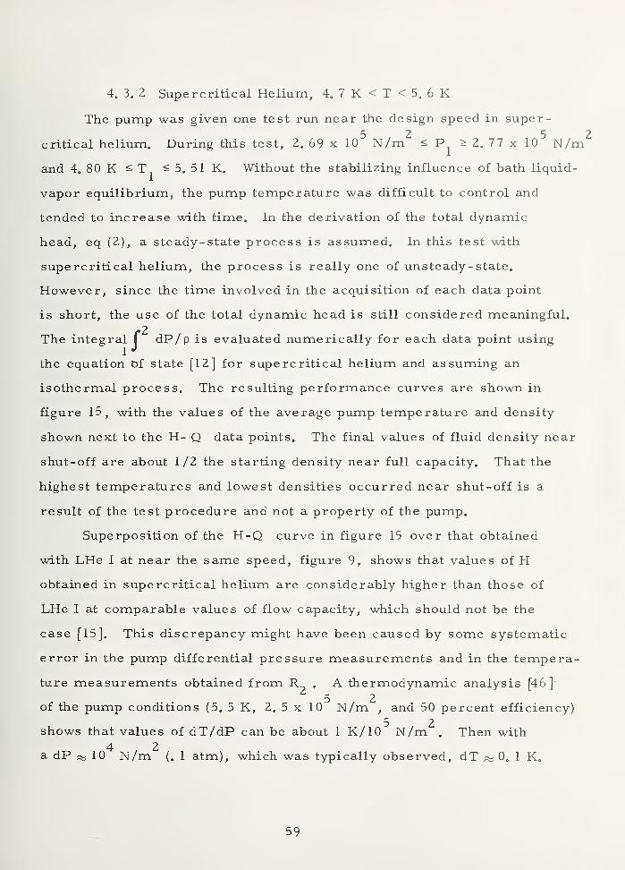
4. 3 P 2 Supercritical Helium, 4.7K<T<5. 6K
The pump was given one test run near the design speed in super-5 2 5
critical helium. During this test, 2. 69 x 10 N/m <s P > 2.77 x 10 N/m
and 4. 80 K ^ T^ ^ 5. 51 K. Without the stabilizing influence of bath liquid-
vapor equilibrium, the pump temperature was difficult to control and
tended to increase with time. In the derivation of the total dynamic
head, eq (2), a steady-state process is assumed. In this test with
supercritical helium, the process is really one of unsteady- state.
However, since the time involved in the acquisition of each data point
is short, the use of the total dynamic head is still considered meaningful.
The integral f dP/p is evaluated numerically for each data point using1J
the equation of state [12] for supercritical helium and assuming an
isothermal process. The resulting performance curves are shown in
figure 15, with the values of the average pump temperature and density
shown next to the H- Q data points. The final values of fluid density near
shut-off are about 1/2 the starting density near full capacity. That the
highest temperatures and lowest densities occurred near shut-off is a
result of the test procedure and not a property of the pump.
Superposition of the H-Q curve in figure 15 over that obtained
with LHe I at near the same speed, figure 9, shows that values of H
obtained in supercritical helium are considerably higher than those of
LHe I at comparable values of flow capacity, which should not be the
case [15], This discrepancy might have been caused by some systematic
error in the pump differential pressure measurements and in the tempera-
ture measurements obtained from R . A thermodynamic analysis [46]"
5 2of the pump conditions (5. 5 K, 2. 5 x 10 N/m , and 50 percent efficiency)
5 2shows that values of dT/dP can be about 1 K/10 N/m . Then with
4 2a dP ~ 10 N/m (. 1 atm), which was typically observed, dT ^ 0. 1 K.
59

4
0 .CAPACITY, m 3/s
Figure 15. Pump performance in supercritical helium, n = 630 rad/s
(6011 rpm).

This is about one order of magnitude higher than that obtained with a
similar analysis for the liquid state. Such variations in temperature
could give errors in fluid density of approximately 20 percent in this
near- critical range, which could possibly account for some of the
discrepancy. The measured temperature difference (T - T ) however
is only a few hundreths of a degree, but since is located some 100 mmfrom the impeller outlet and the thin wall discharge tube is not insulated,
some heat transfer between the bath and the discharge tube occurred.
Any heat transfer between the two should tend to reduce the temperature
of the discharge stream at station 2.
4. 3.3 LHe II, 1, 8 K < T < T.A
At saturated vapor pressures, a transition from LHe I to LHe II
occurs when the temperature T = 2. 172 K. At this temperature, calledA.
the X-point, visible bubble formations which normally occur during
vacuum pumping of the bath suddenly cease, a result of the liquid's
anomalously high thermal conductivity; the transition from LHe I to
LHe II can therefore be easily recognized. At T > T , LHe I behavesA
as an ordinary Newtonian fluid, and is referred to as "normal helium. "
In contrast to this, however, the macroscopic properties of LHe II at
T < T cannot be described by the classical laws of fluid mechanics.A
Its behavior is most simply described phenomenally by a two-fluid
model. The two fluids, termed the "normal fluid" and the "superfluid, "
have temperature dependent densities such that
P + P =.P
,
n s
where p is the ordinary (observed) density of liquid helium. Since the
4liquid at T < T is an assembly of He atoms which are all identical,
A
the two-fluid model does not imply that LHe II is a mixture of two real
61

fluids. This model, which correlates a wide variety of experimental
results, postulates that the superfluid component carries zero entropy
and experiences no flow resistance,, Comprehensive treatments of
the two -fluid model, experiments done in LHe II and their interpretation
are given, for example, by Donnelly [47] and by Wilks [48].
Attempts to use a mechanical pump to transfer LHe II have not
been reported in the literature. The present experiments in LHe II
are therefore believed to be the first attempts to pump superfluid helium.
Although they were not designed or intended to investigate the basic
physics of pumping superfluid, the two experiments in LHe II showed
that LHe II (with approximately 50 percent mass fraction superfluid) can
easily be pumped without significantly increasing the temperature of the
fluid.
In one experiment, the pump was run at a constant speed and
throttling valve setting while the bath temperature was reduced from
above to below the \-point. The results of this experiment are shown
in figure 16. The total dynamic heads and the volumetric rates of flow
measured in LHe II are not significantly different than those in LHe I.
With these data, the main impeller tip speed and relative velocity at
are of the order of 10 m/s. Therefore, the superfluid component is
envisaged to be highly turbulent. At the lowest temperature, T % 1, 9 K,
approximately 50 percent of the liquid mass is superfluid. In these
data, the measured temperature rise across the pump, (T - T ), is
of the order of a few hundreths of a degree.
In another experiment the apparent constant speed performance
characteristics were measured. The term "apparent" is used because
in LHe II measurements of the rate of volumetric flow using a venturi
meter are ambiguous [38]; i. e. , the flow of the superfluid component
through the venturi may not contribute to the measured pressure drop.
The same argument can be applied to the differential pressure measured
across the pump. The resulting pump performance data taken at a
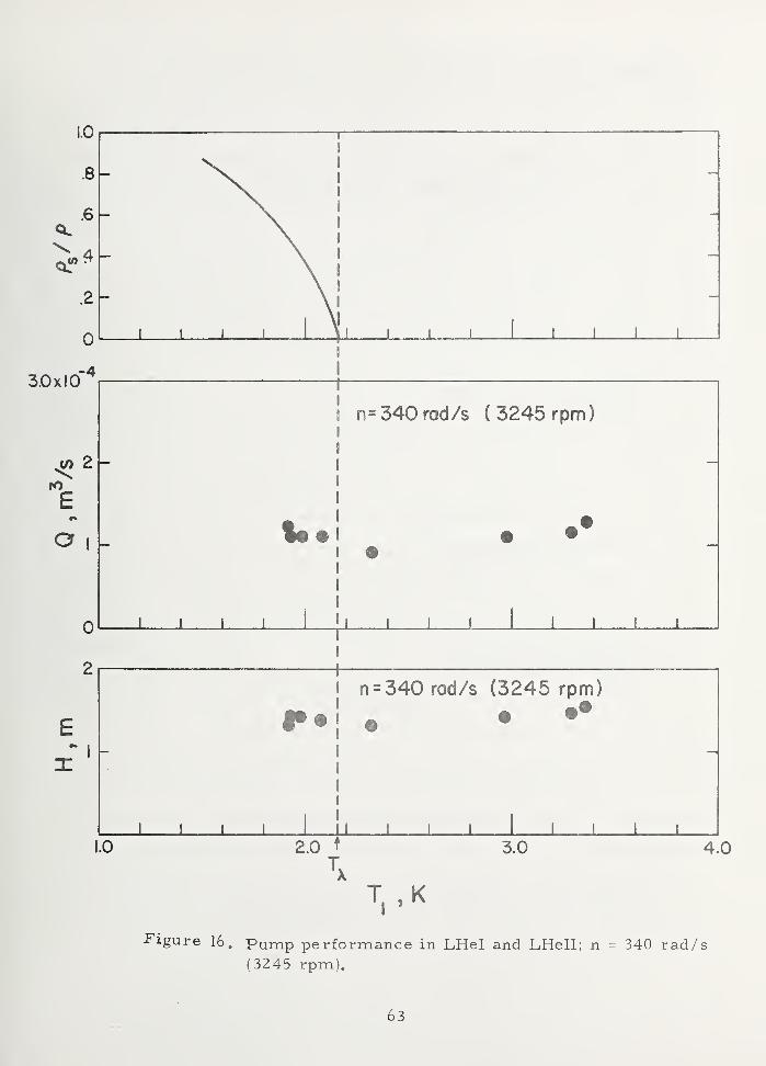
3.0x10
4.0
Figure 16. Pump performance in LHel and LHell; n = 340 rad/s
(3245 rpm).
63

nominal temperature of 1. 89 K, are given in figure 17. The curve
drawn through these H-Q data is obtained from the low speed pump data
obtained with LHe I (curve 2, fig 13) and use of the affinity laws. The
solid circles represent data taken several days previous to those rep-
resented by the open ones. The curves of total efficiency and total
average power as a function of Q (fig. 17) are dissimilar compared to
those typically obtained in LHe I (fig. 12) and supercritical helium
(fig. 15). As mentioned earlier, it would be more meaningful to plot
the shaft power and the pump efficiency rather than the total quantities.
Measurements of the shaft power to the pump should be incorporated in
future work.
It should be noted that the overall performance in superfluid helium
was not greatly different from that which would be scaled by classical
hydrodynamics from measurements in normal helium- -the difference
being certainly less than a factor of two. Probably this comes about
because the impeller tip velocity far exceeds the "critical" velocity of
helium (a few centimeters per second) at which vorticity is generated
in the superfluid. The tangled mass of vortices, so generated, have
been shown to move approximately in accordance with classical hydro-
dynamical equations in many experiments. Our results are in qualitative
accord with this fact.
During the experiments with LHe II, the time for both differential
pressure gages to reach steady values was measurably increased. The
significance of this observation is not well understood at the present
time and may partially be caused by film flow inside the pressure lines.
However, the slower response times did bring to mind critical velocity
experiments which show that the superfluid component will (sometimes)
not interact with a solid surface moving relative to the fluid because of
its frictionless like behavior. In future pump experiments in LHe II, it
would be interesting to see if critical velocity effects exist.
64

15
10
° D D D
TOTAL EFFICIENCY {%)
wTOTAL AVERAGE POWER( watts
)
HTOTAL DYNAMIC HEAD (m)
.40 3x10
APPARENT CAPACITY, mVs
Figure 17. Performance characteristics of He -Pump operating in
LHell; T = 1. 89 K; n = 339 rad/s (3237 rpm);
0, 105 m < NPSH 0. 204 m.
65

4. 3. 4 Comparison of the H-Q Data
Using the pump affinity laws, all of the H-Q data were normalized
to the design speed, 628 rad/s. The results, summarized in figure 18,
show that the LHe I data fall in two zones depending on the speed. The
two zones appear to be off- set by a pure translation in Q about the same
order of magnitude as the estimated "leakage" through the bearing cooling-4 3
holes, Q ?s 0. 6 x 10 m / s. At the lower flow rates, the supercritical
data are considerably higher than all the other data. The LHe II data
are dispersed, with several points falling below the two zones. Possible
reasons for these latter deviations have been discussed earlier.
4. 3. 5 Reliability
The reliability of the helium pump depends on the life of the low
temperature ball bearings and the operation of the submersible motor.
The induction motor used in these tests has good low temperature starting
characteristics and is highly reliable because there are no brushes to
wear out. The helium environment provides adequate bearing cooling
but gives little lubrication to the balls. The ball bearings used in these
experiments, made of 440 C stainless steel, are retained with glass-
reinforced PTFE, impregnated with M S_, . The M provides theo 2 o 2
lubrication. Under normal operating conditions the maximum bearing
5life is estimated to be of the order of 10 hours. Since skidding of the
balls is prevented during rapid motor acceleration by a spring preload
(see fig. 8), the bearing life should not depend on the duty cycle. Impuri-
ties such as ice crystals can be highly abrasive and therefore are a
threat to long bearing life and pump reliability. For this reason, special
care was taken to eliminate traces of water from getting into the helium
bath.
The start-up reliability of the pump was studied in LHe I at
T = 4. 1 K by periodically starting and stopping the pump, while subjected
to a certain load. The nominal load condition, n = 628 rad/s (6000 rpm),
66

SC He 4.80 K < T S 5.51 K
n = 629 rod / s (6011 r/min)
LHeH 1.85 K < T < 1.95 K
n = 339 rod /s (3237 r/min)
LHe I T = 4.02 K
204 rad/s (1952 r/min) < n < 393rad/s(3754r/min)
LHe I 2.23 K < T < 4.20 K
582 rad/s (5553 r/min) < n < 749 rad /s (7154 r/min)
.8 1.2 1.6 2.0
Q ,CAPACITY, mVs
2.4 2.8 3.2x10r4
Figure 18. H-Q data normalized to the design speed, 628 rad/s (6000 rpm)
67

head rise ^5 m, and Q % 2. 5 x 10 m/s, was chosen arbitrarily. Typi-
cal time response curves of the head and capacity are shown in figure 19.
The pump is allowed to run at steady conditions for about 60 seconds.
Fifty (50) such test cycles were performed with no anomalous behavior
observed. For all 50 values of the steady state data, the maximum vari-
ation in head was 4. 0 percent and the maximum variation in capacity was
5. 5 percent. Approximately 30 additional switchings were also performed
during the course of running the standard performance tests.
5. Conclusions
The following is a summary of conclusions formulated from the
results of this work.
1. A pre-induced, single-stage impeller pump is a simple, con-
trollable, and reliable method of generating forced helium flow.
2. A single-stage inducer-impeller pump of simple design can
be used to pump all phases of helium from 1. 85 K to 5. 5 K.
3. A simple inducer-impeller pump can operate satisfactorily in
LHe I and LHe II with little liquid cover. This result may not be
universal and needs further testing and evaluation.
4. Results of non-cavitating pump performance in liquid nitrogen
can be used to estimate non-cavitating pump performance in LHe I.
5. The pump affinity laws are applicable to the non-cavitating
helium pump performance curves provided leakage effects are
accounted for. Additional work is required to improve the design
of helium pumps so that the design point is closer to the measured
performance.
6. The non-cavitating performance of geometrically similar pumps
of different size might be estimated using the results of the present
tests and the pump scaling laws [16, 15, 11], Since the validity of
the scaling laws applied to helium pumps has yet to be tested, the
accuracy of such predictions would be unknown.
68
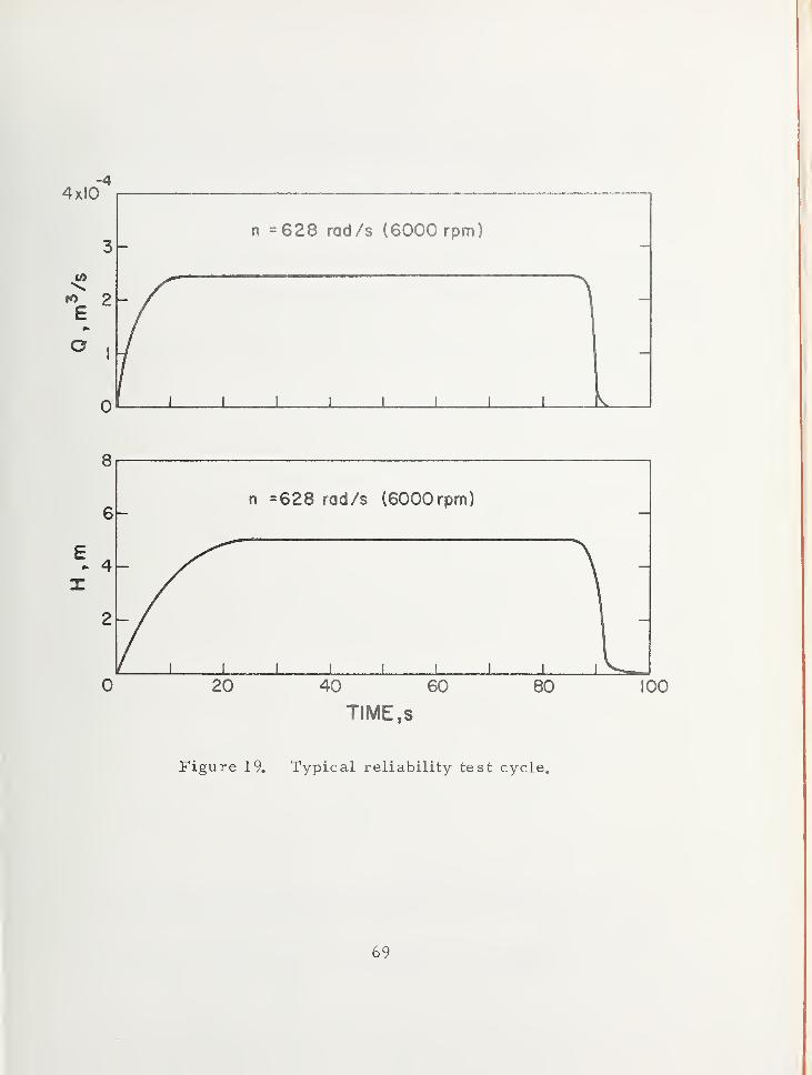
n =628 rad/s (6000 rpm)
J I I L
20 40 60
TIME,s
80 100
Figure 19. Typical reliability test cycle.
69

7. The helium performance of different pumps whose specific
speed at the best efficiency point is approximately 15 (780 [ft, gpm]),
might also be estimated using the results of the present tests, see
for instance Stepanoff [H], p 0 176,, Such predictions are subject to
the same uncertainties as noted in 6.
6. Recommendations for Future Work
Further insight into the detailed behavior of the pump and the
relative importance of some of the parts would have been determined
from the following:
1) Determine the pump efficiency from torque measurements
or from motor efficiency,,
2) Obtain additional pump cavitation data in liquid helium and
in liquid nitrogen or hydrogen to evaluate the performance pre-
diction method developed by Ruggeri, Moore, and Gelder [21,39]=
3) Eliminate the bearing cooling flow of the present design.
We know now that this is not necessary and it adds uncertainty
to the flow measurements.
4) Compare performance with and without the inducer.
5) Streamline the entrance hub nut for better cavitation
performance.
6) Increase the discharge vane angle of the centrifugal impeller
to give a higher head at the design flow.
7) Add pressure taps in the pump housing to determine
1) leakage flow past the inducer,
2) the head rise across the inducer and the centrifugal
impeller,
3) the diffuse r efficiency.
Such instrumentation would give insight for improving the
present design.
Of the above recommendations, items 1 and 2 are considered to be the
most crucial.70

Systematic errors which may have occurred due to thermal
gradients in the pressure lines could possibly be eliminated in future
work by using pressure transducers designed to work at helium tempera-
tures. This would also be a necessary step for automating the data
acquisition and would help remove the ambiguity from pressure measure-
ments made in LHe II.
71
7. References
Morpurgo, M. , A superconducting solenoid cooled by forced
circulation of supercritical helium, CERN Report 69-25,
Geneva (1969).
Sixsmith, H„ , and Giarratano, P, , A miniature centrifugal pump,
Rev. Sci. Inst. 41 , No. 11, 1570-1573 (1970).
Heron, K. , and Cairns, D. N„ H.,Experiments on a pumped
supercritical helium test loop, Central Electricity-
Research Laboratories Report RD/LIN 190/70 (1970).
Keilin, V. E„ , and Klimenko, E„ Yu, Cryogenic problems of
forced cooled superconducting systems, Cryogenics 1
2
,
No. 4, 292-296 (1972).
Snowden, D. P. , Superconductors for power transmission,
Sci. Am. _226, No. 4, 84-91 (1972).
Scott, R. B. ,Cryogenic Engineering, pp. 263-267 (Van Nostrand,
New York, N. Y. , 1959).
Daney, D. E.,Ludtke, P. R.
,Chelton, D. B. , and Sindt, C. F.
,
Slush hydrogen pumping characteristics, Nat. Bur. Stand.
(U.S.), Tech. Note 364 (1968).
Caine, G. H. , and Pradhan, A. V. , Pumps or fans for
destratification of hydrogen liquid and gas, Book, Adv. in
Cryogenic Eng. 13_ , Ed. K. D. Timmerhaus, pp. 728-738
(Plenum Press, New York, N. Y. , 1968).
Urasek, D. C. ,Meng, P. R. , and Connelly, R. E.
,Investigation
of two -phase hydrogen flow in pump inlet line, NASA
TN-D-5258 (1969).
Wright, B. M.,Centrifugal pumping of liquefied gases,
J. Sci. Instruments 44 , 469-470 (1967).
72

11„ Stepanoff, A. J. ,Centrifugal and Axial Flow Pumps, 2 Ed 0
(Wiley and Sons, New York, N. Y. , 1957).
12. McCarty, R. D„ ,Thermodynamic functions for helium 4 for
temperatures from 2 to 1500 K with pressures to
2100 MN/m (1000 atmospheres), Nat. Bur. Stand.
(U.S.), Tech. Note 631 (1972).
13. Cunningham, R. G. ,Hansen, A. G. , and Na, T. Y. , Jet
pump cavitation, ASME Paper No. 69-WA/FE-29 (1969).
14. Wislicenus, G. F 0 , Fluid Mechanics of Turbomachinery
(McGraw-Hill, New York, N. Y. , 1947).
15. Kovats, A. ,Design and Performance of Centrifugal and Axial
Flow Pumps and Compressors (Pergamon Press, New York,
N. Y. , 1964).
16. Lazarkiewicz, S. , and Troskolanski, A. T. ,Impeller Pumps
(Pergamon Press, New York, N. Y. , 1965).
17. Bird, R. ,Stewart, W. E. , and Lightfoot, E. N.
,Transport
Phenomena (Wiley & Sons, New York, N. Y. , I960).
18. Schlichting, H.,Boundary Layer Theory, 4th Ed. (McGraw Hill,
New York, N. Y. , I960).
19. DiStefano, J„ F. , and Caine, G. H.,Cavitating characteristics
of tank mounted cryogenic pumps and their predicted
performance under reduced gravity, PESCO report (1961).
20. Jacobs, R. B. ,Martin, L. B. ,
Hardy, R. J. , Direct
measurement of net positive suction head, J. of Basic
Engineering 81 , 47-152 (1958).
21. Ruggeri, R. S. , and Moore, R. D. , Method for prediction of
pump cavitation performance for various liquids, liquid
temperatures and rotative speeds, NASA Tech. Note
D-5292 (1969).
73

22. Wright, M. K. ,Design comments and experimental results for
cavitation-resistant inducers up to 40, 000 suction specific
speed, J. of Engineering for Power 8_6, 176-180 (1964).
23. Bulletins C-5246, C-5166, and C-5126, Globe Industries , Inc ,
2275 Stanley Avenue, Dayton, Ohio 45404 (1967).
24. Apfel, R c E. , The tensile strengths of liquids, Scientific
American 227, No. 6, 58-71 (1972).
25. Finch, R. D. ,Kagiwada, R. , Barmatz, M. , and Rudnick, I.
,
Cavitation in liquid helium, Phys. Rev. 1 34 , No. 6 A,
1425-1428 (1964).
26. Jacobs, R. B. , Single phase transfer of liquefied gases,
NBS Circular 596 (1958).
27. Schoch, K. F. ,Superconducting cryogenic motors, Book,
Advances in Cryogenic Engineering <6, Ed. K. D„
Timmerhaus, pp. 65-72 (Plenum Press, New York,
N. Y. , 1961).
28. Redmond, J. H. , and Bott, F. W, , Design study of a. c.
motors to operate in helium from liquid to gaseous
state, J. Spacecraft^, No. 9, 1065-1069 (1968).
29. Johnston, H. L. , Liquid Hydrogen: Propellant for aircraft
and rockets, Final Report, Ohio State Research
Foundation, Columbus 10, Ohio (1946).
30. Johnston, H. L. , Liquid Hydrogen: Propellant for aircraft
and rockets, Second Summary Report, Ohio State
Research Foundation, Columbus 10, Ohio (1947).
31. Gottzmann, C. F. ,High pressure liquid-hydrogen and
helium pumps, Book, Advances in Cryogenic
Engineering _5 , Ed. K. D. Timmerhaus, pp. 289-298
(Plenum Press, New York, N. Y. , I960).
74

32. Yonemitsu, H„ , and Okada, J„,Spot-cooling with a cryogenic
pump, Book: Adv. in Cryogenic Engineering 9 ,
Ed. K. D. Timmerhaus, pp. 507-512 (Plenum Press,
New York, N. Y. , 1964).
33. Darrel, B. , and Schoch, K. , An electrically pumped liquid
helium transfer system, Book, Adv. in Cryogenic
Engineering 11 , Ed. K„ D. Timmerhaus, pp. 607-611
(Plenum Press, New York, N. Y, , 1966).
34. Kolm, H. H. ,Leupold, M. J. , and Hay, R. D. , Heat transfer
by the circulation of supercritical helium, Book,
Advances in Cryogenic Engineering 11, Ed. K. D.
Timmerhaus, 530-535 (Plenum Pre s s , New York,
N. Y. , 1966).
35. Mulder, I. J. , A cold transfer system (Proc. 2nd Int.
Cryogenic Conf. Brighton, U. K. , 50, 1968).
36. Wagner , W. , An electrically driven pump and stirring unit
for use at low temperatures and high pressures,
Kaltetechnik-Klimatisierung 22, No. 10, 342-344,
In German, English translation by A. W. Beffie (1970).
37. Mark, J. W. , and Pierce, W. B. , Hydrogen targets at SLAC,
SLAC-PUB-883, Stanford Linear Accelerator Center,
Stanford University 94305 (1971).
38. Meservey, R. ,Superfluid flow in a venturi tube, Phys. of
Fluids 8, No. 7, 1209-1212(1965).
39. Gelder, T. F.,Ruggeri, R. S. ,
Moore, R. D. , Cavitation
similarity considerations based on measured pressure
and temperature depressions in cavitated regions of
freon-114, NASA TN D-3509 (1966).
75

40. Arp, V. ,Ballinger, E. R„ ,
Giarratano, P. J. , and others,
Helium heat transfer, Unpublished NBS Report
(1972).
41. ASME Power Test Code, Chapter 4, Flow Measurement
(Am. Soc. of Mech. Eng., New York, N. Y. , 1959).
42. Hord, J. ,Anderson, L. M, , and Hall, W. J. , Cavitation
in liquid cryogens I_, NASA CR - 2054 (1972).
43. Moore, R. D. , and Meng, P. R. , Comparison of noncavitating
and cavitation performance for 78°, 80. 6°, and 84° helical
inducers operated in hydrogen, NASA TN D-6361 (1971).
44. Pump Manual, prepared by the sub- committee on pumps of
the equipment testing procedures committee. (Am. Inst,
of Chem. Engineers, 345 E. 47th St. , New York, N. Y.
10017, I960).
45. Peck, J. F. ,Design of centrifugal pumps with computer aid,
Proc. of Inst, of Mech. Eng. 183 , Part 1, No. 17,
321-351 (1968-1969).
46. Arp, V. , Forced flow, single -phase helium cooling systems,
Book, Advances in Cryogenic Engineering J_7, Ed. K.
Timmerhaus, pp. 342-351 (Plenum Press, New York,
N. Y. , 1972).
47. Donnelly, R. J. ,Experimental Superfluidity (University of
Chicago Press, Chicago, 111. , 1967).
48. Wilks, J. , The Properties of Liquid and Solid Helium
(Clarendon Press, Oxford, 1967).
49. Wood, G. M. , Visual cavitation studies of mixed flow pump
impellers, J. of Basic Eng., 85, 17-28 (1963).
76

UnclassifiedSecurity Classification
DOCUMENT CONTROL DATA -R&D(Security classification of title, body ot abstract and indexing annotation must be entered when the overall report is classified)
1. ORIGINATING ACTIVITY (Corporate author)
Cryogenics Division
National Bureau of Standards
2a. REPORT SECURITY CLASSIFICATION
unclas sified2b. GROUP
3 REPORT TITLE
LIQUID HELIUM PUMPS
4. DESCRIPTIVE NOTES (Type of report and inclusive dates)
Summary report covering 5/72 through 12/72.5- Au THORiS) (First name, middle initial, last name)
Philip M. McConnell
6- REPOR T DATE
June 1973
7a. TOTAL NO. OF PAGES
81
7b. NO. OF RE FS
498a. CONTRACT OR GRANT NO. 9a. ORIGINATOR'S REPORT NUMBER(S)
MIPR FY 14557200411 NBSIR 73-316b. P ROJ EC T NO.
9b. OTHER REPORT NOISI (Any other numbers that may be assignedthis report)
AFAPL-TR-73-720. DISTRIBUTION STATEMENT
Approved for public release; distribution unlimited.
II. SUPPLEMENTARY NOTES 12. SPONSORING MILITARY ACTIVITY
Air Force Aero-Propulsion lab.
Air Force Systems CommandWright-Patterson Air Force Base, Ohio
13. ABSTRACT
This report summarizes studies of pump characteristics and
performance in supercritical, normally boiling, and superfluid helium,
and also presents results on a survey of commercially available pumpsfor helium service. Experimental measurements were made on a
centrifugal pump which produced a maximum head of about 15 meters,
and a maximum flow of about 2. 5 x 10 m 3/s. Performance agreed
approximately with classical affinity laws, but cavitation appeared to
provide less of a performance limitation than expected. The survey
turned up several pumps which have been used in helium, though
relevant performance data is lacking.
DD FORM1 NOV 651473 Unclassified
SecuntyClassification

UnclassifiedSecurity Classification
1 4.KEY WORDS
LINK A LINK B LINK C
ROLE W T ROLE W T ROLE W T
Cavitation; helium; pumps; pump performancesuperfluid.
Unclas sifiedSecurity Classification

FORM NBS-114A (1-71)
U.S. DEPT. of comm. 1. PUBLICATION OR REPORT NO. 2. Gov't Accession
BIBLIOGRAPHIC DATA NBSIR 73-316N °*
3. Recipient's Accession No.
4. TITLE AND SUBTITLE
LIQUID HELIUM PUMPS5. Publication Date
June 19736. Performing Organization Code
7. author(s) Philip M. McConnelltt Present affiliation: Todd Research and Technical Div.
,
8. Performing Organization
9. PERFORMING ORGANIZATION NAME AND ADDRESS Caiveston, 1 exas
NATIONAL BUREAU OF STANDARDS , Boulder LabsDEPARTMENT OF COMMERCEBoulder, Colorado 80302
10. Project/Task/Work Unit No.
2750459I I. Contract/ Grant No.
MIPR FY14557200411
12. Sponsoring Organization Name and Address
Aero-Propulsion LaboratoryWriaht-Patte rson AFB Ohio 45433
13. Type of Report & PeriodCovered Interim
May - December 1972
14. Sponsoring Agency Code
15. SUPPLEMENTARY NOTES
16. ABSTRACT (A 200-word or less factual summary of most significant information. If document includes a significantbibliography or literature survey, mention it here.)
This report summarizes studies of pump characteristics and performancein supercritical, normally boiling, and superfluid helium, and also presents
results on a survey of commercially available pumps for helium service.
Experimental measurements were made on a centrifugal pump which produceda maximum head of about 15 meters and a maximum flow of about Z, 5 x 10"^ m^/sPerformance agreed approximately with classical affinity laws, but cavitation
appeared to provide less of a performance limitation than expected. The surveyturned up several pumps which have been used in helium, though relevant
performance data is lacking.
17. KEY WORDS (Alphabetical order, separated by semicolons)Cavitation; helium; pump performance; pumps; superfluid.
18. AVAILABILITY STATEMENT 19. SECURITY CLASS 21. NO. OF PAGES(THIS REPORT)
fxl UNLIMITED.UNCLASSIFIED
[ ,FOR OFFICIAL DISTRIBUTION. DO NOT RELEASE 20. SECURITY CLASS 22. PriceTO NTIS. (THIS PAGE)
UNCLASSIFIED
USCOMM-DC 66244-P71
ISCOMM - ua.