Embed Size (px)
Citation preview

IEEE TRANSACTIONS ON INDUSTRIAL ELECTRONICS
Abstract— A subsurface chamber transceiver system and associated propagation channel link budget considerations for an underground wireless sensor system (UWSS) are presented: the application was a sewerage system for a water utility company. The UWSS operates over the GSM850/900, GSM1800/1900 and UMTS bands in order to operate with the standard public mobile phone system. A novel antenna was developed to minimize path loss from the underground location: a folded loop type, which is small enough to fit conveniently inside a utility manhole access chamber while giving adequate signal strength to link to mobile base stations from such a challenging environment. The electromagnetic performance was simulated and measured in both free space and in a real manhole chamber. An experimental test bed was created to determine the return loss and received signal strength with different transceiver positions below the manhole chamber access cover. Both numerical and experimental results suggested an optimum position of the unit inside the manhole, combining easy access for maintenance with viable received signal strength. This confirmed that the characteristics were adequate for incorporation in a transceiver designed to communicate with mobile base stations from underground. A field trial confirmed the successful operation of the system under severe conditions.
Index Terms— link budget, mobile band antenna, GSM, received signal strength, subsurface propagation, UMTS, underground utilities, wireless sensor network.
Manuscript received November 25, 2016; revised March 26, 2017
and May 1, 2017; accepted May 31, 2017. This work was supported partially by Yorkshire Innovation Fund, IETG Ltd. Contract, Research Development Project (RDP) and the European Union’s Horizon 2020 research and innovation programme under grant agreement H2020-MSCA-ITN-2016 SECRET-722424.
C.H. See, R. A. Abd-Alhameed, A.A. Atojoko, and N. J. Mcewan are with the School of Engineering and Informatics, University of Bradford, BD7 1DP, U.K. (e-mails: [email protected], [email protected], [email protected] and [email protected]).
C.H. See is also with School of Engineering, University of Bolton, Deane Road, Bolton, BL3 5AB, UK. (e-mail: [email protected])
P. S. Excell is with Glyndwr University, Wrexham, LL11 2AW, U.K. (e-mail: [email protected])
I. INTRODUCTION
HE sewerage network in the UK, at 302,000 km in length, is one of the largest infrastructures within the water
industry. These assets are aging and are also subject to increasing capacity demands because of increased urbanization, more stringent environmental regulation and the projected consequences of climate change. Currently, the water industry is investing in excess of £200 million per annum in sewer replacement and rehabilitation [1-3]. To proactively reduce their risk of failure and become more operationally efficient, water companies are exploring with organizations, including academia and instrumentation manufacturers, to find solutions for improving the efficiency of responses to failures of key elements of critical infrastructure.
In recent years, wireless sensor network (WSN) research [4-9] has received substantial attention due to its low cost, ease of deployment and successful implementation in a great many applications in business, transportation, government, defense and healthcare. To further explore other potential applications, significant efforts have gone into the development of underground wireless sensor systems (UWSS) [10-12]. These can be a practical solution to allow utility companies to change radically the existing methods of data collection and monitoring of remote assets. Underground environments are obviously lossy for electromagnetic waves since they contain soil, rocks and water, and are relatively complex compared with above-ground environments. To achieve a better transmission range, theory suggests that lower operating frequencies are desirable. These, however, result in larger antennas being deployed underground, which is theoretically desirable but less practical because of limited space in existing manhole chambers etc. For these reasons, it is preferable, if challenging, to use established mobile-band frequencies for wireless sensor to sensor (STS) communications underground, and sensor to base station (STB) communication from underground to above ground [13-14].
To gain better understanding of the RF propagation below ground, extensive measurements and associated simulation modeling have been undertaken and reported in the literature. These cover horizontally, vertically, and cross-polarized signals in underground assets, i.e. mines and tunnels [15],
Link Budget Maximization for a Mobile- Band Subsurface Wireless Sensor in
Challenging Water Utility Environments
Chan Hwang See, Senior Member, IEEE, Raed A. Abd-Alhameed, Senior Member, IEEE, Achimugu A. Atojoko, Neil J. McEwan and Peter S. Excell, Life Senior Member, IEEE
T

IEEE TRANSACTIONS ON INDUSTRIAL ELECTRONICS
manholes [16-17], and a gully pot [18]: all of these research findings show the importance of operating frequency, antenna polarization, and electrical properties of the underground asset walls for the signal propagation characteristics and hence the overall link budget. This shows that the antennas in a wireless system play a pivotal role in enhancing the transmission and reception in such a harsh environment. For this reason, many antenna design concepts [14-25] have been proposed and implemented for underground applications. For STS underground communication, a zig-zag shaped monopole designed for 915 MHz operation [11], and an inverse triangular monopole antenna intended to operate from 900 to 1500 MHz [19], have been explored. For STB underground to above-ground communication, it is noticeable that many antenna design innovations have been developed to establish reliable and longer distance wireless links to above-ground mobile network base stations [20-30]. In some published works [20-23], the authors attempted to convert the conventional manhole cover to operate as an antenna: in [20], a thick slot was cut in a metal manhole cover to form a slot antenna, while in [21] a slot antenna was embedded in a shallow cavity inside a cast-iron manhole cover. As such antennas would be located on the surface of the ground, this reduces the attenuation in the path to the base station. However, such techniques suffer from difficulties of machining the cover and are rather impractical for widespread implementation since covers of different sizes, shapes and materials are available. To solve this problem, a composite manhole cover slot antenna with a sandwich structure was suggested in [22], while in [23] an electronically steerable, linearly spaced parasitic slot array was integrated with a composite manhole cover. Again, using a composite cover is still an expensive solution as all existing metal covers would have to be replaced if large-scale implementation were required.
Apart from modifying manhole covers, other underground antenna designs requiring less disturbance of the infrastructure have also been investigated [24-29]. These include a two-arm conical spiral [24] and normal mode helix antenna [25]. Both of these show that stronger signal reception above the ground can be achieved via radiation of a directed beam, but this is problematic if the above-ground station is not permanently fixed. A three-element wire-based inverted-F antenna array, offering high gain, a unidirectional pattern and polarization diversity was recommended in [26]. In order to reduce scattering, a novel antenna system combined with a carpet cloak and a cavity, possessing steerable radiation patterns was proposed for operation over 8-12 GHz [27]. In addition, a composite right-left handed (CRLH) microstrip patch antenna [28], and a single layer and stacked microstrip antenna [29], have been reported for underground WSNs. Among all the above designs [19-29], it was found that they are mostly only capable of offering narrow single band operation [19-23,25-26,28-29]; only very few such as in [24, 27] can handle wideband operation, with the compromises that that entails, and no design is optimized for dual-band operation. There is also the pragmatic constraint that utility companies do not wish to replace their existing manhole covers, which are predominantly made of cast iron. This
means that a system must be devised which enables sufficient signal to get past the seals of the cast iron cover and through the surrounding concrete and earth in order to access the above-ground part of the propagation path in free space. This short step from the subsurface antenna to open air represents a very severe attenuation in the overall link budget of the communication system and the object of the present work was to find ways to prevent this attenuation from rendering the link budget unviable. To fill this gap, the authors’ earlier work [30] suggested that a dual-band planar folded loop antenna would be a propitious candidate for a wireless sewer condition monitoring system. The lower operating mode can be excited by the full length of the folded loop, while the upper resonant mode is generated by the inverted L-shaped part of the loop. In section II, the detailed design evolution procedure and operating principles are addressed. The antenna as functioning in free space is discussed in section III. EM interaction between antenna and manhole chamber are computationally and experimentally studied in section IV. Finally, conclusions are drawn in section V.
(a) (b)
(c)
Fig. 1. Geometry of the proposed antenna (Units: mm). (a) Top view, (b) Side view, (c) Auxiliary view.
II. TRANSCEIVER AND ANTENNA DESIGN CONCEPTS AND STRUCTURE
The transceiver unit is designed to operate underneath a pre-existing standard metal cover of a manhole chamber and it serves as a data concentrator in an underground WSN system to communicate with an existing long range above-ground mobile communication base station. The antenna design is critical to achieving reliable communication: Fig. 1 depicts the geometry of the proposed antenna, which is constructed as a folded planar loop. Allowing for realistic constraints on acceptable size for incorporation in a manhole chamber, the antenna dimensions and structure were chosen based on [31]. All the geometric parameters were then optimized through parametric studies. To enable its dual-band operating characteristic, a suspended rectangular feeding plate [32] with

IEEE TRANSACTIONS ON INDUSTRIAL ELECTRONICS
an optimized feed gap of 3 mm was used to excite the assembly. As shown in Fig.1, the optimized dimensions of the antenna are 60.5×43.5×47 mm3, equivalent to electrical dimensions of 0.18o×0.13o×0.14o, where o is defined at the center frequency of the lower operating band, taken as 900MHz. This is larger than a conventional mobile antenna, which is typically constrained by product aesthetics, but it is acceptable in this application and offers scope for further refinement. For better performance and ease of integration within a manhole chamber, the antenna is designed to operate externally to the wireless transceiver and is mounted on the center of a 130 x 130 mm2 finite ground plane. It should also be noted that the risk of flammable atmospheres in the sewerage system means that the transceiver module must be in a sealed containment, further indicating the need for a separate antenna.
Fig. 2. Simulated and measured return losses of the proposed antenna.
The basic operational principle of this antenna can be
explained by separating the four differently sized rectangular metal plates which form the complete assembly. Fig. 2 shows the detailed design evolution of the structure from a planar monopole to a folded loop planar antenna, i.e. Stages 1 to 4, while both Figs. 2 and 3 show the performance of the respective antenna geometries, in terms of return loss and input impedance.
As can be seen in Fig. 2, this analysis is divided into four stages: note that the whole structure is centered on the ground plane (not shown in Fig. 2). The approach begins by considering a 44×32.5 mm2 rectangular metal plate fed by an off-center probe with a feed gap of 3 mm. This section constitutes a traditional planar monopole, depicted as Stage 1 of Fig. 2. In this stage, the length of 44 mm, which corresponds to about 0.25λ, was selected to ensure that the antenna operates at the required center operating frequency of the higher GSM band, 1.9 GHz. By optimizing the width and the feed gap of the structure, acceptable impedance matching (better than 8 dB) in the higher operating band was achieved, as shown in Fig. 2. Examining the relevant impedance plot in Fig. 3, it is seen that it exhibits a typical monopole impedance response with a parallel resonance occurring at around 1.9 GHz.
Without extending the height of the monopole component, but to improve the impedance matching in the upper operating band, the next step is to top-load the monopole with a
43.5×60.5 mm2 rectangular capacitive plate to construct an inverted L-shaped antenna structure, as shown in Stage 2, Fig. 2. The return loss plot shows a small improvement over the higher operating band, due to the top-loading effect, which shifts the parallel resonance down from 1.9 GHz to 1.35 GHz. This results in a small variation of the resistance in the higher operating band, from 30 to 58 ohms, and changes the inductive reactance to capacitive, as illustrated in Fig. 3.
Fig. 3. Simulated input impedance of proposed antenna in the design evolution process as depicted in Fig. 2.
(a) 900 MHz (b) 1900 MHz
Fig. 4. Current distributions of the proposed antenna.
To further enhance the impedance matching in the higher
operating band, a metal plate with dimensions of 38×46 mm2 was added at the edge of the top plate and parallel to the feeding plate: this is shown as Stage 3 in Fig. 2. With this modification, the antenna partially resembles a loop antenna with an impedance bandwidth further improved to cover 1710 to 2170 MHz, for a return loss better than 10 dB, as plotted in Fig. 2. Examining the input in Fig. 3, it is evident that this parallel plate further lowers the parallel resonance to 1.17 GHz and results in good matching characteristics, i.e. resistance and reactance vary between 35 to 50 and -20 to 0 ohms, respectively.

IEEE TRANSACTIONS ON INDUSTRIAL ELECTRONICS
Finally, to achieve good matching at the lower operating
frequency band, i.e. 824 to 960 MHz, the antenna was further modified by partially shorting the parallel plate to the ground plane using a 9×3 mm2 metal plate, as shown in Stage 4, Fig. 2. After this step, the impedance response shows that the parallel resonance frequency of the antenna remains, but the resonant impedance reduces from 430 ohms to 140 ohms, as plotted in Fig. 3. It was found, interestingly, that this change increases the resistance of the antenna without altering reactance variation in the lower operating band, in comparison with the earlier form. Because of this, the whole antenna exhibits good impedance matching over the desired lower operating band, as shown in Fig. 2.
Fig. 5. Prototype of the proposed antenna.
Fig. 6. Simulated and measured radiation efficiency and gain of the
proposed antenna.
III. RESULTS FOR ANTENNA IN FREE SPACE
Fig. 5 shows the physical prototype of the antenna which was fabricated from 0.5 mm thick copper sheet. To verify the computed impedance bandwidth performance, the return loss of the prototype was measured using a HP 8510C vector network analyzer. The simulated and measured results show excellent agreement: see Fig. 2. As can be observed, two adjacent resonant frequencies in the range of return loss better than 10 dB occur at 900 MHz and 1900 MHz. These lower and upper modes offer 15.2% and 23.7% relative bandwidth from 824 to 960 MHz and 1710 to 2170 MHz, at a return loss of 10 dB or more. This is completely satisfactory for the desired GSM850, GSM900, GSM1800, GSM1900 and UMTS bands for mobile communication.
Fig. 6 illustrates the simulated and measured peak gain and radiation efficiency of the designed antenna over the frequency ranges 824 to 960 MHz and 1710 to 2170 MHz respectively. In the lower band, a stable measured gain can be observed from 1.0 to 1.9 dBi, with 0.9 dBi gain variations. For the upper band, the measured gain ranges from about 4.2 to 5.8 dBi, with corresponding 1.6 dBi gain variations. The
computed and experimental gain results are essentially indistinguishable. In the lower frequency band, the simulated and measured radiation efficiencies vary from 80% to 88% and 76% to 85% respectively, corresponding to averages of 84% and 80.5% over the operating frequency range. At the upper frequency band, radiation efficiencies of 82% to 95% and 81% to 90% were found for the computed and measured results respectively.
(a) Lower band
(b) Upper band Fig. 7. Simulated and measured normalized radiation patterns of the proposed antenna.
(a) Auxiliary view (b) side view
Fig. 8. Antenna in manhole chamber model (Unit: meters).
The far field radiation patterns of the prototype antenna were measured in an anechoic chamber and the results are presented in Fig. 7. In the far field measurement setup, a calibrated broadband horn (EMCO type 3115) was used as the reference antenna and held at a spacing of 4 m from the antenna under test (AUT).
An elevation-over-azimuth positioner was used, with the elevation axis coincident with the polar axis (θ = 0°) in the AUT coordinate system. The azimuth drive generates cuts at constant ϕ. The elevation positioner was rotated over θ ∈ [-180°, 180°] in 5° increments. The radiation patterns were measured at the six frequencies representing the lower and upper operating bands, i.e. 825, 900, 960, 1750, 1950 and 2150 MHz, and the corresponding results, cross-validated with the simulation data, are plotted in Fig. 7. In the measurement, two pattern cuts (H-plane and E-plane) were recorded at these

IEEE TRANSACTIONS ON INDUSTRIAL ELECTRONICS
selected operating frequencies covering the whole of the designated bandwidths in this study. The total power for both polarizations of the antenna patterns, i.e. vertical and horizontal components, was used. As illustrated in Fig. 7, the radiation patterns are stable, consistent and nearly omnidirectional over all of the targeted operating bands.
(a) AUT at centre of manhole cover.
(b) AUT at a position between the centre and the edge of the
manhole cover.
(c) AUT at the edge of the manhole cover.
Fig. 9. Total Electric Field over the surface of the manhole chamber for various positions of the antenna under test (AUT) at 900 MHz. Left column: 50 cm depth, Middle column: 120 cm depth, Right column: 240 cm depth. The small square represents the location of the antenna.
IV. SYSTEM IN MANHOLE CHAMBER - DESIGN AND
ANALYSIS
In this section, the electromagnetic coupling effects with the simulated and experimental manhole chamber model will be investigated. CST Microwave Studio software [33] was used here to perform the modeling process. A. Simulated Design Model
A realistic manhole simulation model similar to that in [16-18] has been implemented and configured as shown in Fig. 8. As can be seen, it consists of asphalt, a metal cover, concrete, PVC sewer pipes, a neck and chamber. The manhole cover and its pedestal are constructed of cast iron with dimensions of approximately 0.75 × 0.6 × 0.1 m3 and they are buried in the asphalt layer of the ground, with dimensions of approximately 1.7 × 1.7 × 0.1 m3 and with relative permittivity εr = 3.15 and conductivity σ = 0.026 S/m. The neck and the chamber of the manhole are hollow cuboids surrounded by walls constructed of approximately 0.55 m and 0.3 m thicknesses of concrete (εr = 7, σ = 0.12 S/m), respectively. The corresponding dimensions of the neck and chamber are 0.6 × 0.6 × 0.5 m3 and 1.1 × 1.1 × 1.1 m3. At 1.2 m below the asphalt layer, two
orthogonal 0.425 m diameter PVC rectangular blocks (εr = 2.1, σ = 0.0 S/m) were modeled to mimic the drain pipes. The overall envelope size of the model was around 1.7 × 1.7 × 6.8 m3, including the height (5.0 m) of a volume of air region above ground, sufficient to model the local electromagnetic field structure. To simulate the extended air environment and to ensure affordable computational time, this model was truncated by perfectly matched layer (PML) absorbing boundary conditions. To better understand the importance of the transceiver antenna’s position when fitted in the manhole, electric field intensity plots of the model at 900 MHz and 1900 MHz are shown in Figs. 9 and 10 respectively. These figures show the interface plane (xy-plane) between the open air and the manhole model. This provides a good indication of how much electric field can penetrate through the manhole. A preliminary analysis was carried out by investigating four orientations (0°, 90°, 180°, 270°) of the antenna, considering it to be placed at various heights (in the -z direction) and various positions in the x and y directions below ground, as shown in Fig. 8. It should be noted that the 0° and 180° orientations are where the feeding plate of the antenna is nearest to and farthest from the edge, respectively. Interestingly it was found that the antenna provides better electric field penetration to the surface of the ground at 0° orientation than for the other orientations. For the sake of brevity, other cases will not be shown here, and 0° orientation will be kept as a fixed parameter in the study. As can be observed in Figs. 9 and 10, three antenna heights (50, 120 and 240 cm displayed from left to right in the figures) and three positions along the y-axis, (a) center, (b) between center and edge, and (c) edge, were selected to cover possible scenarios for this investigation.
(a) AUT at centre of the manhole cover.
(b) AUT at position between the center and the edge of the
manhole cover.
(c) AUT at the edge of the manhole cover.
Fig. 10. Total Electric Field over the surface of the manhole chamber for various positions of the antenna under test (AUT) at 1900 MHz. Left column: 50 cm depth, Middle column: 120 cm depth, Right column: 240 cm depth. The small square represents the location of the antenna.
x
y
x
y
IEEE TRANSACTIONS ON INDUSTRIAL ELECTRONICS
Examining the total electric field plots at 900 MHz, as in
Fig. 9, the fields are gradually attenuated when the depth of the antenna is increased from 50 cm to 240 cm, for all of the positions. When the antenna is placed underneath the center of the manhole cover, the fields exhibit nearly even distribution over the surface of the model, as shown in Fig. 9(a). This demonstrates that the power distribution in the center of the chamber is more favorable than close to any of the four walls. However, mounting the antenna centrally would obstruct operator access to the manhole for any planned maintenance. Due to this, the antenna is desirably mounted near the wall, even though this incurs some additional attenuation in the link budget from a radio propagation perspective. By moving the antenna from the center to the edge positions, reduced field strengths can be seen at three depth positions when they are compared to the center position. Further moving the antenna to the wall of the chamber and at 50 cm depth, the maximum field strength occurs near to the edge of the metal cover.
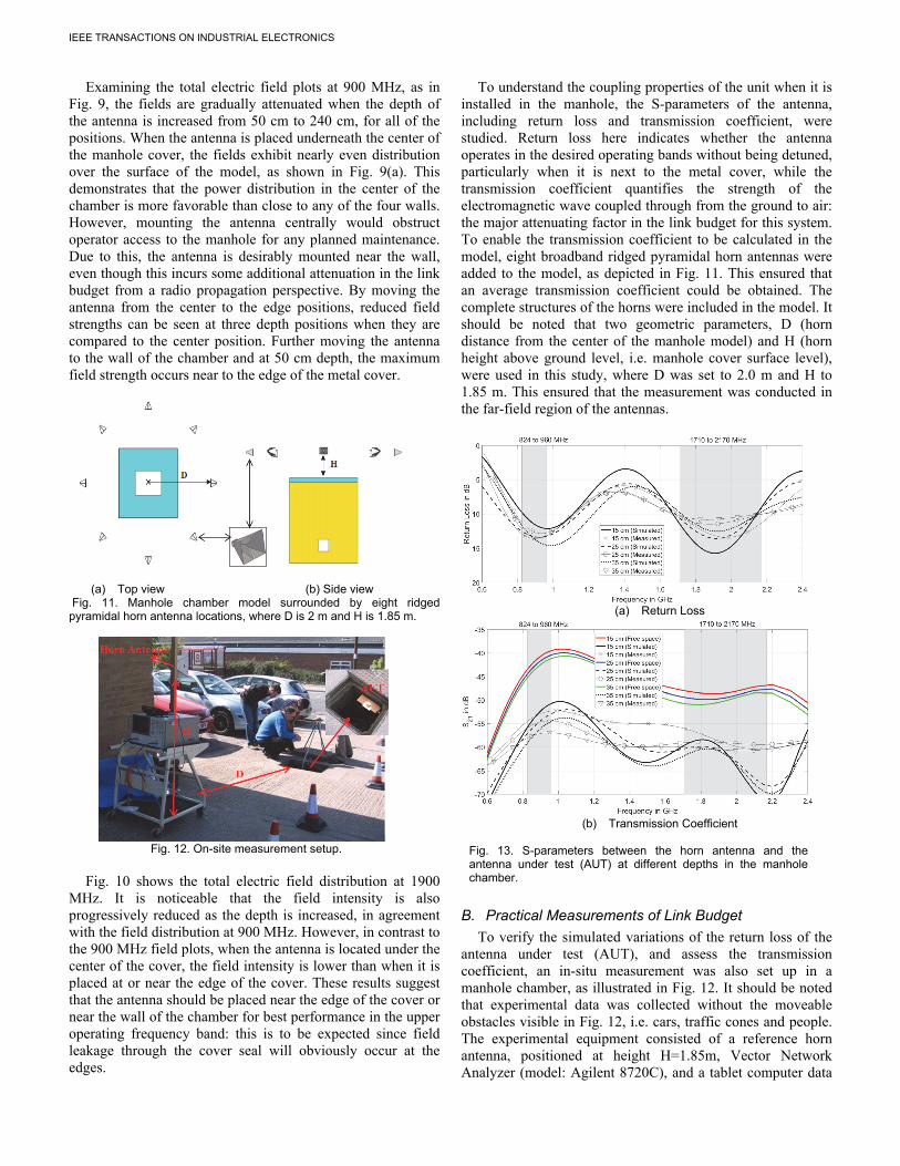
(a) Top view (b) Side view Fig. 11. Manhole chamber model surrounded by eight ridged pyramidal horn antenna locations, where D is 2 m and H is 1.85 m.
Fig. 12. On-site measurement setup.
Fig. 10 shows the total electric field distribution at 1900
MHz. It is noticeable that the field intensity is also progressively reduced as the depth is increased, in agreement with the field distribution at 900 MHz. However, in contrast to the 900 MHz field plots, when the antenna is located under the center of the cover, the field intensity is lower than when it is placed at or near the edge of the cover. These results suggest that the antenna should be placed near the edge of the cover or near the wall of the chamber for best performance in the upper operating frequency band: this is to be expected since field leakage through the cover seal will obviously occur at the edges.
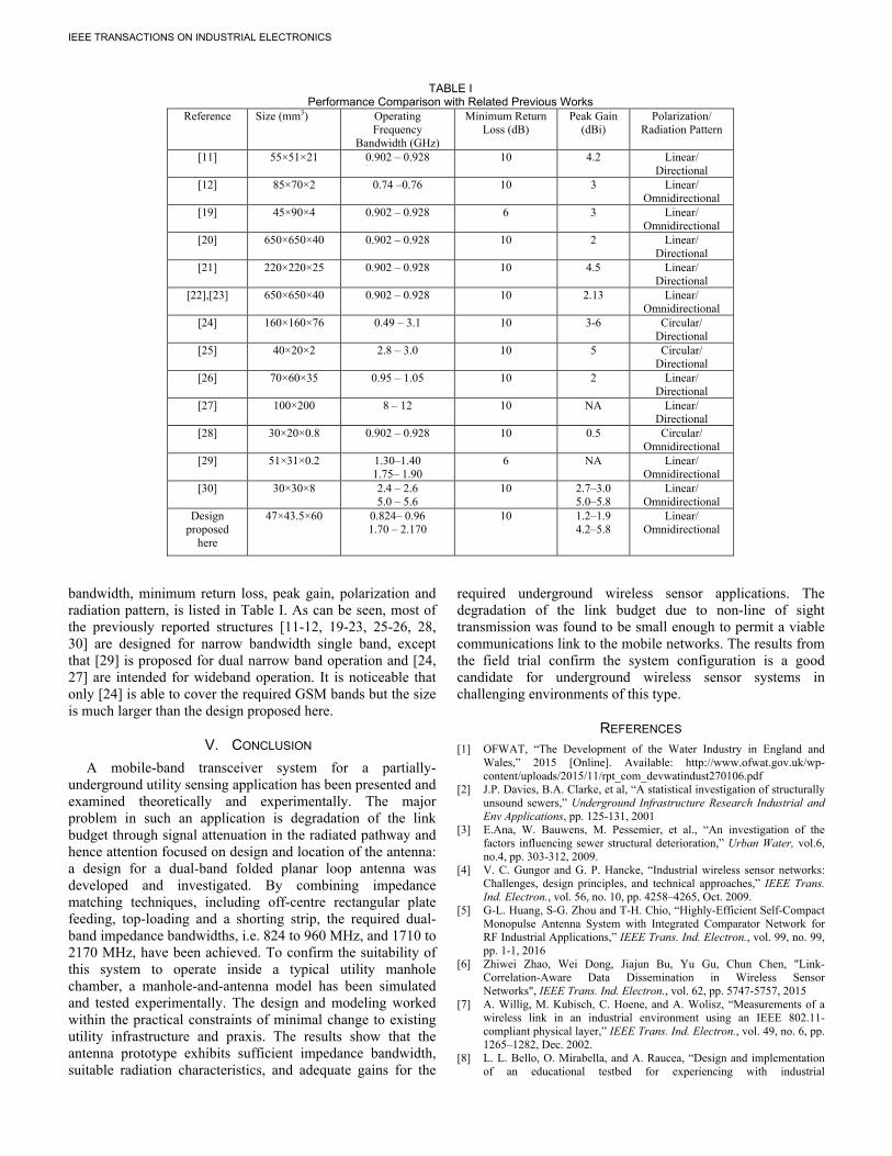
To understand the coupling properties of the unit when it is installed in the manhole, the S-parameters of the antenna, including return loss and transmission coefficient, were studied. Return loss here indicates whether the antenna operates in the desired operating bands without being detuned, particularly when it is next to the metal cover, while the transmission coefficient quantifies the strength of the electromagnetic wave coupled through from the ground to air: the major attenuating factor in the link budget for this system. To enable the transmission coefficient to be calculated in the model, eight broadband ridged pyramidal horn antennas were added to the model, as depicted in Fig. 11. This ensured that an average transmission coefficient could be obtained. The complete structures of the horns were included in the model. It should be noted that two geometric parameters, D (horn distance from the center of the manhole model) and H (horn height above ground level, i.e. manhole cover surface level), were used in this study, where D was set to 2.0 m and H to 1.85 m. This ensured that the measurement was conducted in the far-field region of the antennas.
(a) Return Loss
(b) Transmission Coefficient
Fig. 13. S-parameters between the horn antenna and the antenna under test (AUT) at different depths in the manhole chamber.
B. Practical Measurements of Link Budget
To verify the simulated variations of the return loss of the antenna under test (AUT), and assess the transmission coefficient, an in-situ measurement was also set up in a manhole chamber, as illustrated in Fig. 12. It should be noted that experimental data was collected without the moveable obstacles visible in Fig. 12, i.e. cars, traffic cones and people. The experimental equipment consisted of a reference horn antenna, positioned at height H=1.85m, Vector Network Analyzer (model: Agilent 8720C), and a tablet computer data

IEEE TRANSACTIONS ON INDUSTRIAL ELECTRONICS
acquisition unit. Transmission measurements were taken with the horn antenna at a constant distance of 2 m from the center of the manhole cover. To record the transmission coefficient, the horn and all measuring equipment were moved on a trolley between the eight positions surrounding the metal manhole cover. For all the measurements, the AUT was mounted on a height-adjustable L-shaped support structure in the manhole. For the transmission coefficient measurement, the AUT acted as a transmitter, while the horn antenna played the role of receiver. All of the measured data were recorded five times and then further processed in MATLAB for a better interpretation of the measured datasets. Since mobile base stations are operated with vertical polarization, the antenna in vertical polarization orientation was the primary target for this measurement, however, the two polarizations were considered in the measurements.
(a) Bottom view (b) Top view Fig. 14. Antenna prototype for field trial.
Fig. 13 shows the simulated and measured return losses and
transmission coefficients of the antenna in the manhole chamber. It is noticeable that the antenna preserves good impedance matching (better than 10 dB) over the desired frequency bands, as plotted in Fig. 13(a). The computed and experimental results are in very good agreement. For practical reasons, AUT in-chamber depths of 15, 25 and 35 cm, measured from the ground level had to be used in these tests. For the transmission coefficient at a depth of 15 cm, the measured results show around -52.5 dB to -55 dB at the lower operating band, while at the higher band -56 to -61 dB is observed. Increasing the depth to 25 cm, the results are further reduced by about 2 dB to reach -54.5 dB to -56.5 dB at the lower band and around -58 to -59 dB at the higher band. When the depth reaches 35 cm, the results drop by another 1.5 to 3 dB in the lower band and 2 to 3 dB in the higher band, resulting in ranges of -57.5 to -58 and -60 to -62 dB over the lower and upper bands respectively. Slight discrepancies between simulated and measured results can be attributed to uncertainties in the electrical properties of the materials used in the simulation model, and the simplifications in the simulated structure. Some variation with the weather conditions would also be expected due to their effect on the water content of materials and on the water level in the gully. Also shown in Fig. 13(b) is the simulated coupling level when all material obstructions, including the chamber walls, the asphalt and the manhole cover, are removed. This is the meaning of the free space curves in the plot. As noted, in practical conditions there is no clear line of sight between the antennas, and the direct ray path traverses the asphalt and the chamber walls. The average loss of signal (and hence
degradation of link budget) due to non-LOS conditions is around 10 to 15 dB in the lower band and 8 to 13 dB in the higher band.
Fig. 15. Received signal strength level of transceiver versus the water depth in the manhole chamber in a practical site over a worst-case time period. To further confirm that this system works in the practical environment, an antenna prototype with a radome and wall mounting structure was manufactured for a field trial, as depicted in Fig.14. This prototype was integrated with a Telit HE910 cellular module [34], a data acquisition unit, ATEX (explosive atmosphere) approved enclosure and a commercial ultrasonic sensor [35] to form a water level monitoring system. This system was installed in a manhole chamber and monitored over a period of 3 months. This system was programmed to monitor the water level every 15 minutes: if the water level was above the predefined threshold or battery level was low, an SMS message was sent to report the received signal strength, battery level and water level immediately. If nothing untoward was happening, an SMS message was sent as a system health indicator every 12 hours. The radio module had a receiver sensitivity of -109 dBm and -111 dBm for GSM900 and GSM1800 bands respectively. It was found that the antenna showed a good received signal strength (RSS) level over this field trial: typical worst-case field trial results over a four day period are shown in Fig. 15. As can be seen, the RSS level is between -80 and -96 dBm even for the worst-case condition when it was raining (the ground would then be much more attenuating and water level in the chamber very high). The reference curve shown gives a comparison with the RSS level over a drier period when the water level remained low in the chamber: the RSS level is between -68 and -75 dBm under these conditions. Since the transceiver sensitivity in receive mode was -109 dBm or better, this shows that there was a margin of 34 dB in the link budget in these particular tests. It could not be determined which mobile base station was in communication and it would in any case be difficult to determine its instantaneous transmitted power, but there were no base stations visible in the vicinity. However, the fact that the system functioned satisfactorily and still had such a generous link budget margin gives confidence that it would be viable in a wide range of utility applications.
C. Performance Comparison
A comparison between the proposed antenna and previously published works, in terms of size, operating frequency,
Feed point
Wall mounting structure
Radome
IEEE TRANSACTIONS ON INDUSTRIAL ELECTRONICS
bandwidth, minimum return loss, peak gain, polarization and radiation pattern, is listed in Table I. As can be seen, most of the previously reported structures [11-12, 19-23, 25-26, 28, 30] are designed for narrow bandwidth single band, except that [29] is proposed for dual narrow band operation and [24, 27] are intended for wideband operation. It is noticeable that only [24] is able to cover the required GSM bands but the size is much larger than the design proposed here.
V. CONCLUSION
A mobile-band transceiver system for a partially-underground utility sensing application has been presented and examined theoretically and experimentally. The major problem in such an application is degradation of the link budget through signal attenuation in the radiated pathway and hence attention focused on design and location of the antenna: a design for a dual-band folded planar loop antenna was developed and investigated. By combining impedance matching techniques, including off-centre rectangular plate feeding, top-loading and a shorting strip, the required dual-band impedance bandwidths, i.e. 824 to 960 MHz, and 1710 to 2170 MHz, have been achieved. To confirm the suitability of this system to operate inside a typical utility manhole chamber, a manhole-and-antenna model has been simulated and tested experimentally. The design and modeling worked within the practical constraints of minimal change to existing utility infrastructure and praxis. The results show that the antenna prototype exhibits sufficient impedance bandwidth, suitable radiation characteristics, and adequate gains for the
required underground wireless sensor applications. The degradation of the link budget due to non-line of sight transmission was found to be small enough to permit a viable communications link to the mobile networks. The results from the field trial confirm the system configuration is a good candidate for underground wireless sensor systems in challenging environments of this type.
REFERENCES [1] OFWAT, “The Development of the Water Industry in England and
Wales,” 2015 [Online]. Available: http://www.ofwat.gov.uk/wp-content/uploads/2015/11/rpt_com_devwatindust270106.pdf
[2] J.P. Davies, B.A. Clarke, et al, “A statistical investigation of structurally unsound sewers,” Underground Infrastructure Research Industrial and Env Applications, pp. 125-131, 2001
[3] E.Ana, W. Bauwens, M. Pessemier, et al., “An investigation of the factors influencing sewer structural deterioration,” Urban Water, vol.6, no.4, pp. 303-312, 2009.
[4] V. C. Gungor and G. P. Hancke, “Industrial wireless sensor networks: Challenges, design principles, and technical approaches,” IEEE Trans. Ind. Electron., vol. 56, no. 10, pp. 4258–4265, Oct. 2009.
[5] G-L. Huang, S-G. Zhou and T-H. Chio, “Highly-Efficient Self-Compact Monopulse Antenna System with Integrated Comparator Network for RF Industrial Applications,” IEEE Trans. Ind. Electron., vol. 99, no. 99, pp. 1-1, 2016
[6] Zhiwei Zhao, Wei Dong, Jiajun Bu, Yu Gu, Chun Chen, "Link-Correlation-Aware Data Dissemination in Wireless Sensor Networks", IEEE Trans. Ind. Electron., vol. 62, pp. 5747-5757, 2015
[7] A. Willig, M. Kubisch, C. Hoene, and A. Wolisz, “Measurements of a wireless link in an industrial environment using an IEEE 802.11-compliant physical layer,” IEEE Trans. Ind. Electron., vol. 49, no. 6, pp. 1265–1282, Dec. 2002.
[8] L. L. Bello, O. Mirabella, and A. Raucea, “Design and implementation of an educational testbed for experiencing with industrial
TABLE I Performance Comparison with Related Previous Works
Reference Size (mm3) Operating Frequency
Bandwidth (GHz)
Minimum Return Loss (dB)
Peak Gain (dBi)
Polarization/ Radiation Pattern
[11] 55×51×21 0.902 – 0.928 10 4.2 Linear/ Directional
[12] 85×70×2 0.74 –0.76 10 3 Linear/ Omnidirectional
[19] 45×90×4 0.902 – 0.928 6 3 Linear/ Omnidirectional
[20] 650×650×40 0.902 – 0.928 10 2 Linear/ Directional
[21] 220×220×25 0.902 – 0.928 10 4.5 Linear/ Directional
[22],[23] 650×650×40 0.902 – 0.928 10 2.13 Linear/ Omnidirectional
[24] 160×160×76 0.49 – 3.1 10 3-6 Circular/ Directional
[25] 40×20×2 2.8 – 3.0 10 5 Circular/ Directional
[26] 70×60×35 0.95 – 1.05 10 2 Linear/ Directional
[27] 100×200 8 – 12 10 NA Linear/ Directional
[28] 30×20×0.8 0.902 – 0.928 10 0.5 Circular/ Omnidirectional
[29] 51×31×0.2 1.30–1.40 1.75– 1.90
6 NA Linear/ Omnidirectional
[30] 30×30×8 2.4 – 2.6 5.0 – 5.6
10 2.7–3.0 5.0–5.8
Linear/ Omnidirectional
Design proposed
here
47×43.5×60 0.824– 0.96 1.70 – 2.170
10 1.2–1.9 4.2–5.8
Linear/ Omnidirectional

IEEE TRANSACTIONS ON INDUSTRIAL ELECTRONICS
communication networks,” IEEE Trans. Ind. Electron., vol. 54, no. 6, pp. 3122–3133, Dec. 2007.
[9] S.Zhang and H. Zhang, “A Review of Wireless Sensor Networks and its Applications,” IEEE international conference on Automation and Logistics (ICAL), pp.386-389, 2012.
[10] X.Tan, Z. Sun and I.F. Akyildiz, “Wireless Underground Sensor Network: MI-based communication systems for underground applications,” IEEE Antennas & Propagation Magazine, vol.57, no.4, pp.74-87, 2015
[11] C.H. See, K.V. Horoshenkov, R.A. Abd-Alhameed, Y.F. Hu and S.J. Tait, “A Low Power Wireless Sensor Network for Gully Pot Monitoring in Urban Catchments”, IEEE Sensors Journal, vol.12, no. 5, pp.1545-1553, May 2012.
[12] D. Trinchero and R. Stefanelli, “Microwave Architectures for Wireless Mobile Monitoring Networks inside Water Distribution Conduits,” IEEE Trans. Microwave Theory and Techniques, vol.57, no.12, pp.3298-3306, 2009.
[13] M.D. Bedford and G.A. Kennedy, “Evaluation of ZigBee (IEEE 802.15.4) Time-of-Flight-Based Distance Measurement for Application in Emergency Underground Navigation”, IEEE Trans. Antennas and Propagation, vol.50, no.5, pp.2502-2510, April 2012.
[14] C.H. See, R.A. Abd-Alhameed, D. Zhou, Y.F Hu and K.V Horoshenkov “Measure the Range of Sensor Network”, Microwaves & RF, vol. 54, no.10, pp.69-76, Oct. 2008.
[15] C. Zhou, T. Plass, R. Jacksha and J. A. Waynert, “RF Propagation in Mines and Tunnels,” IEEE Antennas & Propagation Magazine, vol.57, no.4, pp.88-102, 2015.
[16] A. Ando, T. Ito, H. Tsuboi and H. Yoshioka, “Propagation Loss, XPR and Height Pattern Characteristics on Road from Antenna Set in Manhole,” IEEE Antennas and Propagation Society International Symposium (APSURSI), pp.1-4, 2010.
[17] A. Ando, T. Ito, H. Yoshioka, H. Tsuboi and H. Nakamura, “Effects of Receiver Antenna Height and Polarization on Received Signal Levels at Road Level from Transmitter Antennas Set in Manhole,” IEEE International Symposium on Antennas and Propagation (APSURSI), pp.2399-2402, 2011.
[18] S. Mizushina, A. Adachi and T. Watanabe, “Radiation from an antenna in manhole,” Asia-Pacific Microwave Conference (APMC), pp.2052-2055, 2006
[19] A.S. Kesar and E. Weiss, “Wave Propagation between Buried Antennas”, IEEE Trans. Antennas and Propagation, vol.61, no.12, pp.6153-6156, April 2013.
[20] J.F. Mastarone and W.J. Chappell, “Urban Sensor Networking Using Thick slots in Manhole covers,” IEEE Antennas and Propagation Society International Symposium, pp.779-782, 2006
[21] S. Jeong, D. Ha, M.M. Tentzeris, “A Cavity-backed Slot Antenna with High Upper Hemisphere Efficiency for Sewer Sensor Network,” IEEE Antennas and Propagation Society International Symposium (APSURSI), pp.49-50, 2013
[22] S. Jeong, C-L. Yang, J.R. Courter, S. Kim, R.B. Pipes and W.J. Chappell, “Multilayer Composite for Below Ground Embedded Sensor Networking,” IEEE Antennas and Propagation Society International Symposium, pp.1-4,2008
[23] S. Jeong and W.J. Chappell, “Adaptive composite antennas for a city-wide sensor network,” IET Microwaves. Antennas and Propagation, vol.4, no.11, pp.1916-1926, 2010
[24] T.W. Hertel and G.S. Smith, “The Conical Spiral Antenna over the Ground”, IEEE Trans. Antennas and Propagation, vol.50, no.12, pp.1668-1675, December 2002.
[25] D. Ghosh, H. Moon and T.K. Sarkar, “Design of through-the-earth mine communication system using helical antennas,” IEEE Antennas and Propagation Society International Symposium, pp.1-4,2008
[26] R-Y. Chao and K-S. Chung, “A Low Profile Antenna Array for Underground Mine Communication,” Singapore ICCS '94. Conference Proceedings., vol.2, pp.702-709, 1994
[27] W. Tang, Y. Hao, “Cloak on Underground Antenna Using Transformation Electromagnetics,” IEEE International Symposium on Antennas and Propagation (APS/URSI), pp.2865-2868, 2011.
[28] G. Pandey, R. Kumar and R.J. Weber, “A low profile, low-RF band, small antenna for underground, in-situ sensing and wireless energy-efficient transmission, IEEE 11th International Conference on Networking, Sensing and Control (ICNSC), pp.179-184, 2014.
[29] P. Soontornpipit, C.M. Furse, Y.C. Chung and B.M. Lin, “Optimization of a Buried Microstrip Antenna for Simultaneous Communication and
Sensing of Soil Moisture”, IEEE Trans. Antennas and Propagation, vol.54, no.3, pp.797-800, 2006.
[30] C.H. See, R.A. Abd-Alhameed, D.Zhou and P.S. Excell,“Dual-Frequency Planar Inverted F-L-Antenna (PIFLA) for WLAN and Short Range Communication Systems”, IEEE Transactions on Antennas and Propagation, vol.56, No.10, pp.3318-3320, Oct. 2008
[31] J.-S. Row, S.-H. Yeh, and K.-L. Wong, “A wide-band monopolar plate patch antenna,” IEEE Trans. Antennas Propag., vol. 50, no. 9, pp. 1328–1330, 2002
[32] R. Feick, H. Carrasco, M. Olmos, and H. D. Hristov, “PIFA input bandwidthenhancement by changing feed plate silhouette,” Electron. Lett., vol. 40, pp. 921–922, Jul. 2004.
[33] CST STUDIO SUITE, available: https:// www.cst.com [34] Telit HE910 Cellular radio module, available:
http://www.telit.com/fileadmin/user_upload/products/Downloads/3G/xe910/Telit_HE910_Hardware_User_Guide_r27.pdf
[35] Hawkeye Ultrasonic level sensor, available: http://www.isodaq.co.uk/clear_downloads/146_1393261032hawkeye2-2007_001.pdf
Chan Hwang See (M’14, SM’15) received a first class B.Eng. Honours degree in Electronic, Telecommunication and Computer Engineering and a Ph.D. degree from the University of Bradford, UK in 2002 and 2007, respectively. He is a Senior Lecturer (Programme Leader) in Electrical & Electronic Engineering, School of Engineering, University of Bolton, UK. He also is a Visiting Research Fellow in School of Engineering and Informatics, University of Bradford, UK. Previously, he was a Senior
Research Fellow in the Antennas and Applied Electromagnetics Research Group within the University of Bradford. His research interests cover wireless sensor network system design, computational electromagnetism, antennas and acoustic sensor design. He has published over 160 peer-reviewed journal articles and conference papers. He is a co-author for one book and three book chapters. He was a recipient of two Young Scientist Awards from the International Union of Radio Science (URSI) and Asia-Pacific Radio Science Conference (AP-RASC) in 2008 and 2010, respectively. He was awarded a certificate of excellence for his successful Knowledge Transfer Partnership (KTP) with Yorkshire Water on the design and implementation of a wireless sensor system for sewerage infrastructure monitoring in 2009. Dr. See is a Chartered Engineer, Member of the Institution of Engineering and Technology. He is also a Fellow of The Higher Education Academy and Associate Editor for IEEE Access.
Raed Abd-Alhameed (M’02, SM’13) received the B.Sc. and M.Sc. degrees from Basrah University, Basrah, Iraq, in 1982 and 1985, respectively, and the Ph.D. degree from the University of Bradford, West Yorkshire, U.K., in 1997, all in electrical engineering. He is Professor of Electromagnetic and Radio Frequency Engineering at the University of Bradford, UK. He has long years’ research experience in the areas of Radio Frequency, Signal Processing, propagations,
antennas and electromagnetic computational techniques, and has published over 500 academic journal and conference papers; in addition he is co-authors of three books and several book chapters. At the present he is the leader of Radio Frequency, Propagation, sensor design and Signal Processing; in addition to leading the Communications research group for years within the School of Engineering and Informatics, Bradford University, UK. He is Principal Investigator for several funded applications to EPSRCs and leader of several successful knowledge Transfer Programmes such as with Arris

IEEE TRANSACTIONS ON INDUSTRIAL ELECTRONICS
(previously known as Pace plc), Yorkshire Water plc, Harvard Engineering plc, IETG ltd, Seven Technologies Group, Emkay ltd, and Two World ltd. He has also been a co-investigator in several funded research projects including: 1) H2020 MARIE Skłodowska-CURIE ACTIONS: Innovative Training Networks (ITN) “Secure Network Coding for Next Generation Mobile Small Cells 5G-US”, 2) Nonlinear and demodulation mechanisms in biological tissue (Dept. of Health, Mobile Telecommunications & Health Research Programme and 3) Assessment of the Potential Direct Effects of Cellular Phones on the Nervous System (EU: collaboration with 6 other major research organizations across Europe). He was awarded the business Innovation Award for his successful KTP with Pace and Datong companies on the design and implementation of MIMO sensor systems and antenna array design for service localizations. He is the chair of several successful workshops on Energy Efficient and Reconfigurable Transceivers (EERT): Approach towards Energy Conservation and CO2 Reduction that addresses the biggest challenges for the future wireless systems. He has also appointed as guest editor for the IET Science, Measurements and Technology Journal since 2009, and 2012. He is also a research visitor for Wrexham University, Wales since Sept 2009 covering the wireless and communications research areas. His interest in computational methods and optimizations, wireless and Mobile communications, sensor design, EMC, beam steering antennas, Energy efficient PAs, RF predistorter design applications. He is the Fellow of the Institution of Engineering and Technology, Fellow of Higher Education Academy and a Chartered Engineer.
Achimugu Alpha Atojoko was born in Nigeria, he received his B.Eng degree in Electrical & Computer Engineering from the Federal University Of Technology Minna in 2004 and he was awarded an MSc degree in Personal, Mobile & Satellite Communications from the University of Bradford in 2010. He has international working experience across the Banking, Manufacturing, Oil & gas and the Telecommunications industry. He is currently a
PHD student at the University of Bradford, UK. His research interests are in the area of Electromagnetics and Radio Frequency Engineering with particular focus on: RFID sensor networks; Antenna design, modelling and deployment for surface and underground wireless sensor applications.
Neil J. McEwan received the M.A. degree in mathematics from Cambridge University, Cambridge, U.K., and the Ph.D. degree in radio astronomy from Manchester University, Manchester, U.K., in 1975.He has held the title of Reader in Electromagnetics at the University of Bradford, West Yorkshire, U.K., since 1986. He was a visiting Research Scientist with Millitech Corporation, South Deerfield, MA, from 1987 to 1989, working on 94 GHz quasi-optical
antennas. He was a Principal Research Engineer with Filtronic, Shipley, U.K., from 1998 to 2007 where he was concerned with handset and base-station antennas for mobile telephony. Since 2008 he has worked as RF Design Engineer with Saras Technology Ltd., Leeds, U.K. He has published over 100 refereed journal and conference papers on aspects of microwave antennas and tropospheric microwave propagation. He is a Chartered Engineer and Fellow of The IET.
Peter S. Excell (M’80, SM’84) received the B.Sc. degree in engineering science from Reading University, Reading, U.K., in 1970, and the Ph.D. degree for research in electromagnetic hazards from Bradford University, West Yorkshire, U.K., in 1980. He is Professor Emeritus of Communications at Wrexham Glyndŵr University, Wrexham, Wales, where he was Deputy Vice Chancellor until 2015. Until 2007 he was Associate Dean for
Research in the School of Informatics at the University of Bradford. His academic interests are concentrated in the area of telecommunications, specifically wireless technologies, electromagnetics and antennas, plus broader interests in mobile communications, future communications applications, and technological evolution. He has published over 450 papers and holds three patents. He is a member of the executive committees of the UK and Ireland section of the IEEE Society for the Social Implications of Technology and of the Engineering Professors’ Council (UK), He is a Chartered Engineer and Chartered IT Professional, a Fellow of the Institution of Engineering and Technology, the British Computer Society and the Higher Education Academy, a Senior Member of the IEEE and a member of the Association for Computing Machinery, the Bioelectromagnetics Society and the Applied Computational Electromagnetics Society.