Embed Size (px)
Citation preview

HAL Id: hal-01100934https://hal.archives-ouvertes.fr/hal-01100934
Submitted on 7 Jan 2015
HAL is a multi-disciplinary open accessarchive for the deposit and dissemination of sci-entific research documents, whether they are pub-lished or not. The documents may come fromteaching and research institutions in France orabroad, or from public or private research centers.
L’archive ouverte pluridisciplinaire HAL, estdestinée au dépôt et à la diffusion de documentsscientifiques de niveau recherche, publiés ou non,émanant des établissements d’enseignement et derecherche français ou étrangers, des laboratoirespublics ou privés.
Linear dynamics of the Lamb-Chaplygin dipole in thetwo-dimensional limitV. Brion, D. Sipp, L. Jacquin
To cite this version:V. Brion, D. Sipp, L. Jacquin. Linear dynamics of the Lamb-Chaplygin dipole in the two-dimensionallimit. Physics of Fluids, American Institute of Physics, 2014, 26, pp.064103. �10.1063/1.4881375�.�hal-01100934�

Linear dynamics of the Lamb-Chaplygin dipole in the two-dimensional limitV. Brion, D. Sipp, and L. Jacquin Citation: Physics of Fluids (1994-present) 26, 064103 (2014); doi: 10.1063/1.4881375 View online: http://dx.doi.org/10.1063/1.4881375 View Table of Contents: http://scitation.aip.org/content/aip/journal/pof2/26/6?ver=pdfcov Published by the AIP Publishing Articles you may be interested in The laminar wake behind a 6:1 prolate spheroid at 45° incidence angle Phys. Fluids 26, 113602 (2014); 10.1063/1.4902015 On the lock-on of vortex shedding to oscillatory actuation around a circular cylinder Phys. Fluids 25, 013601 (2013); 10.1063/1.4772977 Optimal transient disturbances behind a circular cylinder in a quasi-two-dimensional magnetohydrodynamic ductflow Phys. Fluids 24, 024105 (2012); 10.1063/1.3686809 Dipole evolution in rotating two-dimensional flow with bottom friction Phys. Fluids 24, 026602 (2012); 10.1063/1.3680870 Two-dimensional vortex shedding of a circular cylinder Phys. Fluids 13, 557 (2001); 10.1063/1.1338544
This article is copyrighted as indicated in the article. Reuse of AIP content is subject to the terms at: http://scitation.aip.org/termsconditions. Downloaded to IP:
144.204.16.1 On: Fri, 19 Dec 2014 10:27:34

PHYSICS OF FLUIDS 26, 064103 (2014)
Linear dynamics of the Lamb-Chaplygin dipolein the two-dimensional limit
V. Brion, D. Sipp, and L. JacquinONERA, 8 rue des Vertugadins, 92190 Meudon, France
(Received 26 June 2013; accepted 19 May 2014; published online 12 June 2014)
The dynamics of the Lamb-Chaplygin dipole in the large-wavelength limit is in-vestigated by means of linear analysis. Taking the three-dimensional spectrum ofthe Lamb-Chaplygin dipole calculated by Billant [“Three-dimensional stability of avortex pair,” Phys. Fluids 11, 2069 (1999)] as a reference, we first show that addi-tional families of unstable modes are present in the spectrum. Among them, a familyof symmetric modes and one of antisymmetric modes, both present in the large-wavelength limit, are the main topic of this investigation. The most unstable modesin these two families being purely two-dimensional, the two-dimensional dynamicsis more particularly investigated. Our calculations show that the amplification rateof the antisymmetric instability is significantly larger than that of the symmetricinstability. Also, while the two-dimensional symmetric mode is stationary and in-duces a shift of the dipole toward the upstream or downstream direction relativelyto the dipole self-propagation velocity vector, the antisymmetric mode is unsteadyand displaces the dipole into wavy oscillations about its initial straight trajectory.The leading physical mechanism of these two-dimensional instabilities is the vor-tex shedding that occurs downstream of the dipole. This shedding is the reactionof the external flow to the dipole motion and basically enables the conservation ofthe flow impulse. The destabilizing action of the wake is amplified as the displaceddipole generates more shedding. The dipole motion and the wake thus reinforce eachother, leading to the instability. The strain mutually exerted by the vortices of thedipole, known as an essential mechanism of three-dimensional vortex pair instabili-ties, is also shown to participate to this destabilization. C© 2014 AIP Publishing LLC.[http://dx.doi.org/10.1063/1.4881375]
I. INTRODUCTION
This paper deals with the three-dimensional (3D) stability of the Lamb-Chaplygin dipole (here-after referred to as the LCD) in the long-wavelength limit. The LCD flow has been described indetail by Meleshko and Van Heijst.1 While the 3D spectrum of the LCD has already been calculatedby Billant et al.,2 our calculations demonstrate the existence of additional modes. Some of themare in the long-wavelength limit where they dominate the three-dimensional dynamics in terms ofamplification rate. In particular, two-dimensional (2D) modes are found that do not seem to havebeen described in the literature before, even when taking into account vortex pairs other than theLCD. The goal of the present paper is to present these 2D modes and to describe their dynamics inthe linear regime.
It is important to note at first that there seems to be no clear understanding of the 2D stabilityof vortex pairs. In fact, the few available results appear conflicting. According to Saffman,3 counter-rotating vortex patches should be stable to infinitesimal 2D disturbances but Saffman and Szeto4
found that pairs of counter-rotating vortices were unstable to antisymmetric disturbances and stableto symmetric ones. Yet the analysis of Saffman and Szeto4 is limited to the case of vortex patchesand their results are mainly qualitative. Also the results of Crow5 obtained in the case of a pair ofvortex filaments show that such a flow is only unstable in 3D, and thus stable in 2D. Finally, the
1070-6631/2014/26(6)/064103/22/$30.00 C©2014 AIP Publishing LLC26, 064103-1
This article is copyrighted as indicated in the article. Reuse of AIP content is subject to the terms at: http://scitation.aip.org/termsconditions. Downloaded to IP:
144.204.16.1 On: Fri, 19 Dec 2014 10:27:34

064103-2 Brion, Sipp, and Jacquin Phys. Fluids 26, 064103 (2014)
results obtained by direct numerical simulations of 2D dipoles, such as those of Van Geffen and VanHeijst6 for the Lamb-Chaplygin dipole or those of Delbende and Rossi7 for a generic dipole, showno sign of instability.
Conversely, the question of 2D stability is rather well described in the case of a single vortex.The flow made up of such a vortex embedded in a uniform and irrotational strain represents asimplified flow of a vortex pair, which is thus of direct interest to the present study. The 2D dynamicsof a single vortex appears to be very rich. If we first consider the case where the strain is absent,theory predicts that the flow should be stable, however unsteady vortex solutions exist, such asthe Kirchoff vortex which correspond to a steadily rotating ellipse that turns with angular velocity� = ω0a1a2/ (a1 + a2)2 where a1,2 are the ellipse semi-axes and ω0 is the constant vorticity insidethe patch. Within the limit of infinitesimal ellipticity a1 � a2, the Kirchoff vortices rotate at a rateof � = ω0/4.
The presence of strain makes the dynamics potentially unstable. Moore and Saffman8 showedthe existence of steady solutions to a vortex patch in the presence of strain, described by the relation
γ
ω0= a1a2 (a1 − a2)
(a1 + a2)(a2
1 + a22
) ,
where γ is the applied strain rate. The flow stability is then determined by the strain. For moderatestrain |γ /ω0| < 0.15 two solutions of the Moore and Saffman equation exist that differ in the value ofa1/a2 relatively to a threshold value equal to 2.9. The two solutions exhibit different linear stabilitybehavior. The temporal exponent of both solutions is equal to
σ 2ms = ω2
0
4
((2mab
a21 + a2
2
− 1
)2
−(
a1 − a2
a1 + a2
)2m)
(1)
which depends on the azimuthal periodicity m of the disturbances (note that the subscript “ms”refers to the names of the authors). This relation shows that the case m = 1 is always unstable. Theinstability in this case corresponds to a translation of the ellipse in the outward direction of strainwithout any modification of the shape of the ellipse. This effect is well described by consideringthe stability of a point vortex in the presence of another point vortex of opposite circulation ±�
(with � > 0), the two vortices being separated by a distance b. It is straightforward to show that theposition of one vortex moves in the direction of strain following
dx
dt= γ y,
dy
dt= γ x (2)
in which the strain rate is
γ = �
2πb2. (3)
Robinson and Saffman9 also predicted this m = 1 instability. Relation (1) also shows that unstablemodifications of the ellipse shape occur for m = 2 but only if a1/a2 > 2.9, the flow being otherwisestable.
The vortices of the LCD are characterized by a1/a2 = 1.6. The results of Moore and Saffman8
suggest that they should be unstable to the m = 1 displacement instability. This will be shown to beone of the ingredients of the instabilities to which this work is dedicated, but not the entire story.As a remark, it is also worthwhile to note that while the 2D dynamics is free of the fundamentalmechanisms of 3D instabilities (like the Crow and Widnall instabilities), such as bending, tilting,and stretching, the study of Moore and Saffman8 shows that the strain is still an active destabilizingmechanism.
In terms of applications, the question of the 2D stability of vortex pairs is of fundamentalimportance for all the situations in which the flow is constrained to be 2D. Geophysical flows,either in the atmosphere or in the ocean, belong to this category. The dynamics of cyclones andanticyclones, for instance, determines everyday weather. In aeronautics, contrails can be reasonablysimplified as 2D flows and are important for determining the impact of aviation on climate change.In the ocean, dipoles can form by the roll-up of a jet flow out of a basin connected to a sea by a
This article is copyrighted as indicated in the article. Reuse of AIP content is subject to the terms at: http://scitation.aip.org/termsconditions. Downloaded to IP:
144.204.16.1 On: Fri, 19 Dec 2014 10:27:34

064103-3 Brion, Sipp, and Jacquin Phys. Fluids 26, 064103 (2014)
channel with tidal flushing (see Wells and Van Heijst10) and, for example, influence the depositionof sediments and the behavior of fish. Dipoles can also form when streams interact with coasts, forinstance, around the southern coast of Madagascar (see De Ruijter et al.11) or in the wake of islands.Khvoles et al.12 investigated the stability of modons with respect to various forms of perturbationin the context of geophysical flows. Even if the results do not apply to the present case becausethe Coriolis force is not taken into account here, the oscillations of the modon about its centerlineand the emission of vorticity observed by Khvoles12 bear a close resemblance to the dynamics ofthe antisymmetric mode detailed in the present paper. In the context of 2D turbulence, Dritschel13
investigated the interactions of vortex pairs. He showed how an initial well-balanced dipole exhibitsan antisymmetric destabilization that provokes the removal of vorticity from one of the vorticesand a subsequent return of the pair to an equilibrium state. This short review shows that a betterunderstanding of the dynamics of vortex pairs is of high interest to progress with the interpretationof several practical problem in fluid mechanics.
Our approach in this paper is first to recalculate the three-dimensional spectrum of the LCD thatwas found by Billant et al.2 and then to point out the modes in the large-wavelength limit that had notbeen described in this previous work. Two families of modes are found, one belonging to the subsetof symmetric modes uS and the other belonging to the antisymmetric subset uA. Hereafter, we willuse the capital letters A and S to denote the antisymmetric and symmetric subsets, respectively, andwe will largely make reference to mode A and mode S in the core of the article. It will be shown thatthe mode S corresponds to a growing shift of the dipole position either upstream or downstream andthat the mode A induces growing oscillations of the dipole about its natural, undisturbed trajectory.
The paper is organized as follows. In Sec. II, we present the method for the linear stabilityanalysis and the numerical framework. In Sec. III, we first present the complete spectrum of theunstable modes associated with the S and A subsets. Most of the modes are those that have alreadybeen found by Billant et al.2 However, we highlight one family of modes in the A subset and anotherone in the S subset. We analyse the associated linear dynamics in Secs. IV A–IV C and propose aphysical scenario to explain how these instabilities develop in Sec. V.
II. STABILITY ANALYSIS
A. Governing equation
We consider the flow made up of two vortices whose evolution is described by the Navier-Stokesequations in their incompressible form
∇ · u = 0,
dudt
= −∇ p + νu.(4)
Cartesian coordinates x = (x, y, z) are used throughout this study. The vortex axis is z, and x andy are the space coordinates in the transverse directions. In this paper, x is along the horizontal andy is along the vertical. The vorticity vector is noted ω = (ξ, η, ζ ) (note that we use the scalar ω
later on to denote the frequency). We suppose that the vortices are slightly perturbed and thereforedecompose the flow as a sum comprising a base flow, namely, the stationary and 2D vortex pair,and three-dimensional unsteady perturbations. The velocity field associated with the perturbationsis u′ = (u, v, w) and that of the base flow is u = (u, v, 0). Note that the base flow depends onlyon x and y and is assumed parallel in the z direction. The pressures are noted p′ and p. The totalvelocity field writes u = u + εu′ with ε taken infinitesimal (same for pressure). The equation for theperturbation dynamics is obtained by introducing the velocity field decomposition into the NavierStokes equations (4) and neglecting all O
(ε2
)terms
∇.u′ = 0,
∂u′
∂t+ u.∇u′ = −u′ · ∇ u − ∇ p′ + νu′.
(5)
This article is copyrighted as indicated in the article. Reuse of AIP content is subject to the terms at: http://scitation.aip.org/termsconditions. Downloaded to IP:
144.204.16.1 On: Fri, 19 Dec 2014 10:27:34

064103-4 Brion, Sipp, and Jacquin Phys. Fluids 26, 064103 (2014)
Let us introduce O the point located midway between the two vortices. Due to the symmetry ofthe base flow about the (Oxz) plane, perturbations can be divided into two subsets. The first subsetcomprises A perturbations u′
A which are characterized by even axial vorticity about the (Oxz) plane.The second subset comprises S perturbations u′
S which correspond to perturbations with odd axialvorticity about the (Oxz) plane. This writes
u′A : ζ ′(x,−y, z) = ζ ′(x, y, z), u′
S : ζ ′(x,−y, z) = −ζ ′(x, y, z). (6)
A convenient manner to interpret these symmetries is the following: S perturbations lead to symmetricdeformations of the vortices about the symmetry plane while A perturbations lead to deformationswith a twofold symmetry with respect to the mid point O between the two vortices of the pair.
Note that the axial component of the S and A perturbation vorticity can be obtained through thefollowing relations:
ζ ′A (x, y, z) = ζ ′(x,y,z)+ζ ′(x,−y,z)
2 , ζ ′S (x, y, z) = ζ ′(x,y,z)−ζ ′(x,−y,z)
2 . (7)
The base flow being 2D, the perturbations can be additionally decomposed into axial waves ofcomplex amplitude u (x, y, t) = (u, v, iw) (note the absence of dependence on z here), i.e.,
u′ (x, y, z, t) = u (x, y, t) eikz + c.c., (8)
where c.c. stands for the complex conjugate and k is the axial wavenumber, which is real in thepresent case as we perform a temporal stability analysis.
B. Base flow
The LCD is chosen as the base flow. The LCD is the juxtaposition of a rotational flow containedinside a disc of radius D/2 and an irrotational flow that goes past the disc at an incoming speed U .The LCD is a steady solution of the steady Euler equations. It can be characterized by the relationshipbetween its vorticity field ζ and its stream function ψ . Inside the disc, the relationship is linear.Meleshko and Van Heijst,1 who provide the theoretical background for the LCD flow, use a constantβ such that ζ = −β2ψ . Outside the disc, β is nil. Note that it is fair to mention that several authorsmentioned the LCD flow prior to Meleshko and Van Heijst1 but this is clearly stated in their articleso the interested reader can learn the complete history there.
This linear relationship is a particular solution of the equation ψ = f (ψ) characterizingsteady solutions of the Euler equations (note that other solutions of this kind are given by Hesthavenet al.14). Introducing r and θ the polar coordinates in the (Oxy) plane, the stream function of theLCD is given by
ψ(r, θ ) =
⎧⎪⎪⎨⎪⎪⎩
C J1 (βr ) sin θ if r ≤ D/2
Ur
(1 − D2
4r2
)sin θ if r ≥ D/2
, (9)
where J1 is the Bessel function of the first kind and
C = − 2U
β J0 (βD/2). (10)
The velocity U can also be interpreted as the propagating velocity of the dipole. Indeed, the dipoleis self-propelled due to the induction of each vortex upon the other. The value of β is imposedby the continuity of the tangential velocity at the boundary of the dipole and is thus chosen suchthat J1 (βD/2) = 0. This condition yields βD = 2.4394π and finally gives U = 0.91982�/ (π D)where again, � is the circulation of one vortex.
Figure 1 shows the streamlines and the base flow axial vorticity ζ in the reference frame attachedto the vortex pair. The separating streamline between the rotational and the external flow is usuallydenoted as the Kelvin oval, and is a circle of radius R = D/2 in the present case. The flow outsidethe oval goes from left to right as indicated by the black arrows. All quantities are referenced on thepropagating velocity U and dipole diameter D. Thereafter we will use the superscript “∗” to denote
This article is copyrighted as indicated in the article. Reuse of AIP content is subject to the terms at: http://scitation.aip.org/termsconditions. Downloaded to IP:
144.204.16.1 On: Fri, 19 Dec 2014 10:27:34

064103-5 Brion, Sipp, and Jacquin Phys. Fluids 26, 064103 (2014)
FIG. 1. Contours of the axial vorticity ζ and streamlines of the LCD.
normalized quantities, such as the non-dimensional wavenumber k∗ = k D. The Reynolds numberwrites Re = U D/ν.
An important parameter for the vortex dynamics is the aspect ratio a/b of the dipole, where ais the dispersion radius defined by
a2 =∫
y>0
[(x − xc)2 + (y − yc)2
] |ζ |dxdy
�(11)
with (xc, yc) taken as the vorticity centroid of the top vortex. The values of a, b, and a/b can be usefulto draw comparisons so we give them here, based on the diameter D: b � 0.46D, a � 0.206D, anda/b � 0.45.
In the linear stability analysis, we suppose that the base flow is frozen. While this is notrigorously the case since the baseflow diffuses due to viscosity, this approach is classic in vortexstability analysis. The reasoning behind it is that the perturbation time scale tperturbation is muchsmaller than the baseflow time scale tbase associated with viscous diffusion. However, in the lightof the results obtained in the present work, the question of the frozen baseflow hypothesis appearsmore difficult than for the classic approach, because viscous diffusion at the perturbation order playsan important role in the instability dynamics. A thorough analysis of the problem is only achievedin Sec. VI at the end of the article, once all the information derived from this work is available, andconcludes the validity of this approach.
As for now, we only recall the case of 3D perturbations which is the usual basis for thishypothesis. The perturbation time scale is that associated with the mutual strain rate γ between thevortices, already given in (3). As a consequence, tperturbation � γ −1 = 2πb2/�. The time scale ofthe base flow is associated with the viscous diffusion of the vortices and writes tbase � a2/ν. The ratiort = tbase/tperturbation is what matters to justify the frozen base flow approach. This ratio is equal tort = �/ (2πν) (a/b)2 and simple algebra leads to rt = 0.5Re (a/b)2 if one uses the approximation� � π DU . This last expression is based on the point vortex approximation of the drift velocity ofthe vortex pair U � �/ (2πb). Moreover, we use b � D/2 according to the values provided in theprevious paragraph. Note that the true drift velocity is in fact lower than this point vortex model(see Delbende and Rossi7 for more details) but we neglect this effect here. The frozen base flow isjustified if the Reynolds number is large enough to compensate for the small value of (a/b)2.
Another point of concern is the vorticity profile of the LCD, which is not differentiable at theoval boundary as a result of the absence of viscosity in the Lamb-Chaplygin model. This peculiarityhas never been mentioned by any previous authors but could play a role on the perturbation dynamicsaccording to the linearized equation for the axial vorticity in which the derivatives of the base flowvorticity appear. It turns out that the sharpness of the vorticity profile at the oval boundary has noeffect on the stability results. Indeed, we considered the stability of a smooth dipole that has nosuch sharpness in its vorticity profile. By performing the same stability analysis (which is detailedin Appendix A) we found the same 2D unstable modes. This smooth dipole was obtained by a
This article is copyrighted as indicated in the article. Reuse of AIP content is subject to the terms at: http://scitation.aip.org/termsconditions. Downloaded to IP:
144.204.16.1 On: Fri, 19 Dec 2014 10:27:34

064103-6 Brion, Sipp, and Jacquin Phys. Fluids 26, 064103 (2014)
numerical simulation of an initial flow composed of two Lamb-Oseen vortices as in Sipp et al.15 andis characterized by an aspect ratio a/b = 0.3 close to that of the LCD.
C. Global modes and numerics
The temporal stability of the base flow is investigated by looking for positive values of theamplification rate of the global modes (u, p) defined by
(u, p) = (u, p) (x, y) eikz+(σ+iω)t , (12)
where σ is the growth rate and ω is the frequency of the global mode. The velocity and pressure fieldsare defined spatially by q (x, y) = (u, v, w, p). The introduction of the global mode decompositioninto the linearized equations (5) leads to the following eigenvalue problem which is parameterizedby k and Re:
Ak,Re q = (σ + iω) B q, (13)
where matrices Ak,Re and B are given by
Ak,Re =([−u.∇ + 1
Re ]I − ∇u −∇
∇T 0
)B =
(I 0
0 0
), (14)
where T stands for the conjugate transpose operator, I is the identity matrix, = ∂xx + ∂yy − k2,and ∇T = (
∂x , ∂y,−k). The solutions of (13) are calculated by the Arnoldi method implemented in
the Arpack library coupled with a LU inversion algorithm. This method provides a selected numberof eigenvalues and the corresponding eigenvectors in the vicinity of a prescribed guess value. Weperformed several calculations with this method to span a significant part of the parameter space(k, Re) in the low Reynolds Re < 3180 and wavenumber region k > 0. Owing to the fact that thematrices Ak,Re and B in Eq. (13) are real, λ and its conjugate are companion solutions of (13).
All the modes are normalized to unit kinetic energy. Unsteady modes are rearranged suchthat their phase is zero at x = 0. This last operation does not change the results since Eq. (13)is unchanged when a phase shift is applied but enables an easier comparison between modes. Toimpose unit kinetic energy ‖q‖ = 1, we adopt the following scalar product:
〈q1, q2〉 =∫
qT1 B q1dx. (15)
The matrices Ak,Re and B are built using the finite element code FreeFem++ (see Hecht et al.16).Spatial discretization elements P2 and P1 are used for the velocity and the pressure, respectively.The numerical domain consists of a square centered on the vortex pair which has a side-length equalto 10D. A Dirichlet boundary condition u′ = 0 is specified at inflow and side frontiers and a usualoutflow condition is set at the outlet. A convergence study was performed in terms of the size of thecomputational domain and of the spatial resolution to make sure that the results did not suffer fromthe influence of the boundaries (which induce image vorticity) and from numerical diffusion. Inparticular, no influence of the domain length behind the dipole was found. Finally, we verified thatthe 3D spectrum provided by Billant et al.2 was successfully retrieved by our method. The resultsof this comparison are given in Appendix B.
III. 3D STABILITY
The complete spectrum of the LCD has been calculated for Re = 1280. Figure 2 shows thespectra associated with modes S and A (see Subsection II A for the definition of these symmetries).We consider the normalized values of the growth rate and frequency, σ ∗ and f ∗ given by
σ ∗ = σD
U, f ∗ = ω
D
2πU. (16)
The square symbols are white or black to indicate either nil or finite frequency. The modes found byBillant et al.2 are fully recovered. Modes that are not dominant are also found. This is an advantage
This article is copyrighted as indicated in the article. Reuse of AIP content is subject to the terms at: http://scitation.aip.org/termsconditions. Downloaded to IP:
144.204.16.1 On: Fri, 19 Dec 2014 10:27:34
064103-7 Brion, Sipp, and Jacquin Phys. Fluids 26, 064103 (2014)
k*
σ*
0 5 10 15 20 25 300
1
2
3
14
910
11
12
13
(b)
k*
σ*
0 5 10 15 20 25 300
1
2
3
8
2
1
3
6
7
f *=0 >0
54
(a)
FIG. 2. Three-dimensional spectrum of the LCD at Re = 1280. (a) A spectrum. (b) S spectrum. The black and white fillinginside the square symbols indicate the finite or nil value of the normalized frequency.
of the method used for the calculation of the modes, that enables to look for eigenvalues that are notmaximum. In comparison, Billant et al.2 used linearized simulations to calculate the unstable modes.This method limits the search to the most unstable modes (albeit further developments also enablethe calculation of non-maximal modes). The spectra appear to be very rich when compared to thespectra obtained for lower aspect ratio dipoles (see Tsai and Widnall17 and Sipp and Jacquin,18 forinstance). It is supposedly the large aspect ratio of the LCD that gives rise to this unstable dynamicswhich is continuously spred over the three-dimensional range of axial wavenumbers k.
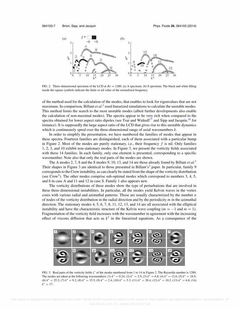
In order to simplify the presentation, we have numbered the families of modes that appear inthese spectra. Fourteen families are distinguished, each of them associated with a particular bumpin Figure 2. Most of the modes are purely stationary, i.e., their frequency f is nil. Only families1, 2, 3, and 10 exhibit non-stationary modes. In Figure 3, we present the vorticity fields associatedwith these 14 families. In each family, only one element is presented, corresponding to a specificwavenumber. Note also that only the real parts of the modes are shown.
The A modes 2, 7, 8 and the S modes 9, 10, 13, and 14 are those already found by Billant et al.2
Their shapes in Figure 3 are identical to those presented in Billant’s2 paper. In particular, family 9corresponds to the Crow instability, as can clearly be stated from the shape of the vorticity distribution(see Crow5). The other modes comprise sub-optimal modes which correspond to numbers 3, 4, 5,and 6 in case A and 11 and 12 in case S. Family 1 also appears new.
The vorticity distributions of these modes show the type of perturbations that are involved inthese three-dimensional instabilities. In particular, all the modes yield Kelvin waves in the vortexcores with various radial and azimuthal patterns. Those are usually characterized by the number nof nodes of the vorticity distribution in the radial direction and by the periodicity m in the azimuthaldirection. The stationary modes 4, 5, 6, 7, 8, 11, 12, 13, and 14 are all associated with the ellipticalinstability and have the characteristic structure of the Kelvin wave coupling (m = −1 and m = 1).Fragmentation of the vorticity field increases with the wavenumber in agreement with the increasingeffect of viscous diffusion that acts as k2 in the linearized equations. As a consequence of the
FIG. 3. Real parts of the vorticity fields ζ ′ of the modes numbered from 1 to 14 in Figure 2. The Reynolds number is 1280.The modes are taken at the following wavenumbers: (1) k∗ = 0.24, (2) k∗ = 2.9, (3) k∗ = 6.8, (4) k∗ = 12.6, (5) k∗ = 18.9,(6) k∗ = 25.2, (7) k∗ = 9.2, (8) k∗ = 15.5, (9) k∗ = 2.4, (10) k∗ = 5.3, (11) k∗ = 20.4, (12) k∗ = 10.2, (13) k∗ = 6.8, (14)k∗ = 17.
This article is copyrighted as indicated in the article. Reuse of AIP content is subject to the terms at: http://scitation.aip.org/termsconditions. Downloaded to IP:
144.204.16.1 On: Fri, 19 Dec 2014 10:27:34

064103-8 Brion, Sipp, and Jacquin Phys. Fluids 26, 064103 (2014)
complete filling of the oval by the base flow vorticity, the modal vorticity is also distributed over theentire oval and even leaks outside of it.
In Secs. IV A and IV B, we will look successively into two specificities of the spectrum pertainingto the large-wavelength domain that have not been investigated before. The first point concerns theexistence of a family of S modes that is not visible in Figure 2(b) because its extent in wavenumberspace and amplification rate are too small (the presentation is done in Sec. IV A). The second pointconcerns the family numbered 1 in Figure 2(a) which comprises three-dimensional large wavelengthmodes.
IV. 2D STABILITY
A. Mode S
A new family of stationary and symmetric unstable modes was found in the large-wavelengthlimit, that we thereafter call mode S for convenience. The dependence of the growth rate upon theReynolds number and wavenumber is explicated in Figure 4. The instability arises above the criticalReynolds number Rec,S = 363 and the most unstable mode is 2D. The growth rate of the modeincreases between Rec,S and Re = 1460 and steadily decreases above. The instability is reducedfor non-zero wavenumbers, i.e., when 3D effects take place. There is an associated cutoff which isequal to k∗ � 2.8 for Re = 1280 used to calculate Figure 4(b).
The vorticity field associated with the 2D mode is shown in Figures 5(a) and 5(b). It featuresa real and an imaginary part that show exactly opposed shapes although one has to note that theimaginary part shown in Figure 5(b) has much lower vorticity levels than the real part. The sameiso-contours have been used but the associated vorticity values have been increased by a factor 50in the plot of the imaginary part. The mode is complex but the frequency is nil. The mode is thusstationary. The real and the imaginary parts correspond to two possible and opposite perturbationstates.
The most prominent feature of the mode S is its m = 1 azimuthal structure in the vortex cores,with n = 0. Modes with m = 1 and n = 0 are known as displacement modes because they inducethe displacement of the vortex as a whole. We also note that there is a quasi-symmetry of the modeabout the (Oy) axis and that its structure remains unchanged when k varies.
The mode features four tails of vorticity downstream of the dipole that leak from the positiveand negative vorticity distributions attached to the dipole. The comparison between the circulations
FIG. 4. Growth rate of mode S. (a) As a function of the Reynolds number. (b) As a function of the wavenumber at Re = 1280as in Figure 2.
FIG. 5. Vorticity of mode S at k = 0 and Re = 1280. (a) Real part of the mode. (b) Imaginary part of the mode. In frame(b), the iso-contours are increased 50 times compared to frame (a). The levels of iso-contours have been adjusted in order tomake apparent the tail of vorticity behind the dipole.
This article is copyrighted as indicated in the article. Reuse of AIP content is subject to the terms at: http://scitation.aip.org/termsconditions. Downloaded to IP:
144.204.16.1 On: Fri, 19 Dec 2014 10:27:34

064103-9 Brion, Sipp, and Jacquin Phys. Fluids 26, 064103 (2014)
FIG. 6. Vorticity field obtained by artificially displacing the LCD dipole. (a) The dipole is displaced to the left. (b) Thedipole is displaced to the right.
inside and outside the dipole, measured by �′inside and �′
outside which are defined by
�′inside =
∫r<D/2 , y>0
ζ ′(x, y, t)dxdy, �′outside =
∫r>D/2 , y>0
ζ ′(x, y, t)dxdy (17)
shows that the perturbation total circulation �′ is equal to �′outside + �′
inside = 0. The integrals arecalculated only in upper domain y > 0 so that the symmetry effect is removed. As will be discussedlater (see Sec. V), total circulation is a conserved quantity, and this is also true at perturbationlevel. This necessarily imposes �′ = 0. An interpretation of the effect of mode S on the flow isobtained by considering the sum of the vorticity of the mode and that of the base flow displayed inFigure 1. Doing so indicates that mode S leads to a shift of the dipole to the left (real part) or to theright (imaginary part). This view is confirmed by considering a small displacement of the base flowto the left and to the right. The modifications to the flow implied by this displacement are shown inFigure 6 and agree well with the vorticity distribution of the unstable mode.
B. Mode A
The spectrum associated with family 1 is shown in Figure 7. What we now call mode A makesthe dipole unstable to large wavelength perturbations when the Reynolds number is larger thanRec,A = 22. This critical Reynolds number is lower than for mode S. Mode A is strongest for k = 0and exhibits a maximum at Re = 223. This maximum growth rate equals σ ∗ = 0.69. The growthrate can also be evaluated in units of the induced strain rate γ = �/2πb2. The calculation yields2πb2/� � 0.46 (D/U ) so that max (σ ) = 0.69 [U/D] = 0.32
[�/
(2πb2
)].
Figure 8 shows the vorticity field of the most unstable mode (k = 0 and Re = 223). The realand imaginary parts of the mode represent the flow at a π/2 phase interval. They both featuredisplacement modes inside the dipole that merge at the mid-plane.
Like mode S, mode A features a wake downstream of the dipole. This wake is composed ofalternating positive and negative vorticity regions along the (Ox) direction. The conservation of totalcirculation of the flow, which is nil initially (i.e., for the baseflow) imposes that total perturbation
FIG. 7. Domain of instability of the LCD featuring the normalized growth rate σ ∗ = σ D/U in frame (a) and the normalizedfrequency f ∗ = ωD/ (2πU ) in frame (b) as a function of k∗ and Re.
This article is copyrighted as indicated in the article. Reuse of AIP content is subject to the terms at: http://scitation.aip.org/termsconditions. Downloaded to IP:
144.204.16.1 On: Fri, 19 Dec 2014 10:27:34

064103-10 Brion, Sipp, and Jacquin Phys. Fluids 26, 064103 (2014)
FIG. 8. Perturbation vorticity of mode A at k = 0 and Re = 223. (a) Real part of the mode. (b) Imaginary part.
FIG. 9. Vorticity field of the unstable mode A for three values of the Reynolds number: (a) Re = 32, (b) Re = 96, (c)Re = 478. The same iso-values have been used in the three frames. A low iso-value has been added to highlight the wakedownstream of the dipole. The dipole and the symmetry line are indicated by the white lines.
FIG. 10. Vorticity field obtained by artificially moving the LCD. (a) Effect of an upward translation. (b) Effect of a clockwiserotation.
circulation �′ = �′inside + �′
outside = 0, with these circulations defined in (17). The calculation ofthese circulations with the modal vorticity field shows that this is indeed the case.
The effect of viscosity on the wake is illustrated in Figure 9 which shows the real part of thevorticity field associated to mode A for three different Reynolds numbers. Since the wake containsvorticity levels much lower than those present in the oval, an iso-contour with a low value ofvorticity is added in the uniformly distributed set of iso-values. While the part of the mode in theoval shows almost no variation as a function of the Reynolds number, except a lowering of thevorticity magnitude, the part of the mode outside the oval seems to extend further as the Reynolds isdecreased. For instance, the vertical extent of the wake is seen to increase greatly with the Reynoldsnumber, being large at Re = 32 which is just above the threshold of instability (frame (a)) andnarrow when the Reynolds number is an order of magnitude larger (frame (c)). In the same way, theupstream part of the perturbation vorticity protrudes further upstream as the viscosity is increased.Using the entire data set we find that the spatial extension of the perturbation vorticity field, taking,for instance, the width of the vorticity wake as a measure of this extension (taken as the verticalextent of the perturbation vorticity field at a given location sufficiently downstream of the dipole),scales as Re−1/2.
The vorticity distribution of mode A can be interpreted by superposing the perturbation andthe base flow vorticity fields (using Figures 1 and 8). The displacement modes in the state shownin Figure 8(a) induce the displacement of both vortices in the upward direction. In Figure 8(b), theupper and lower vortices are moved to the upper right and lower left, respectively. Therefore, thereal part of the mode corresponds to an upward displacement of the dipole and the imaginary partcorresponds to a clockwise rotation. In these movements, the dipole is moved almost as a whole.To confirm this, we calculated the modification of the base flow when it is subjected to (i) a solidupward translation and (ii) a solid clockwise rotation. The results, shown in Figure 10 agree wellwith Figure 8, and confirm the scenario.
This article is copyrighted as indicated in the article. Reuse of AIP content is subject to the terms at: http://scitation.aip.org/termsconditions. Downloaded to IP:
144.204.16.1 On: Fri, 19 Dec 2014 10:27:34

064103-11 Brion, Sipp, and Jacquin Phys. Fluids 26, 064103 (2014)
FIG. 11. Time sequence of mode A during one period of oscillation at Re = 223 and k = 0. The frames show the totalvorticity field ζ at different times corresponding to 10 × t/TA . In the first frame, α and d denote the angle of the displacementand the vertical displacement of the dipole.
C. Linear evolution of mode A in 2D
This section is devoted to the description of the unsteadiness associated with mode A at k = 0.Figure 11 shows the time sequence of the total vorticity ζ (x, y, t) composed of the base flow vorticityζ (x, y) and of the most unstable mode shown in Figure 8, i.e.,
ζ (x, y, t) = ζ (x, y) + εζ ′(x, y, t) (18)
with the value of ε chosen arbitrarily large to highlight the dipole oscillations. Figure 12 showsthe simultaneous evolution of the sole perturbation vorticity ζ ′ (x, y, t). In these time sequences,the time frame covers the full oscillation period of mode A, i.e., TA = 2π/ωA at Re = 223 andk = 0, with a time step equal to 0.1TA. Initially, the flow is in the state corresponding to the real partof the mode shown in Figure 8(a). The imaginary part of the mode shown in Figure 8(b) appearsbetween steps 2 and 3. In Figure 11, only two levels of iso-contours were used in order to simplifythe structure of the flow. The amplification factor has also been turned off to make apparent thekinematics of the instability alone.
The time evolution helps to understand how the translation and rotation movements previouslyidentified act together. We monitor the rotation of the dipole by the tilt angle α schematized in thefirst frame of Figure 11. This angle measures the orientation of the line linking the vortex centersabout the horizontal axis. The translation of the dipole is monitored by its vertical position d. Inframe 0, the dipole is shifted upward (d > 0) and is almost horizontal (i.e., α � π/2). The dipolethen starts to rotate counter-clockwise. At the same time, a downward motion begins which lastsup to step 5. Rotation stops between steps 3 and 4, and reverses to start a clockwise movementin the following time steps. We then observe the same kinematics but with opposite directions:the upward motion follows the clockwise rotation, and the kinematics goes back to step 0. Interms of perturbation vorticity, the time sequence in Figure 12 shows that the dipole oscillations areassociated with the countergrade rotation of the displacement modes in each vortex core. In addition,looking simultaneously at Figures 11 and 12 shows that the clockwise rotation of the dipole leadsto the shedding of positive vorticity (and therefore counter-clockwise rotation is associated withnegative vorticity). This phenomenon is coherent with the conservation of total circulation in theflow �′
outside = −�′inside that was mentioned previously.
This description leads us to interpret the up and down movements of the dipole as a consequenceof the orientation α. Remember that the dipole is self-propelled to the left as a consequence of itsown induction. Therefore, when the dipole tilts, it changes the orientation of the propagation velocityvector: upward for α < π/2 and downward otherwise. In the reference frame attached to the baseflow, this modification takes the form of almost purely vertical movements. Figure 13(a) shows the
FIG. 12. Same as Figure 11, but showing the evolution of the perturbation axial vorticity ζ ′. The grey scale is chosen identicalto that in Figure 8.
This article is copyrighted as indicated in the article. Reuse of AIP content is subject to the terms at: http://scitation.aip.org/termsconditions. Downloaded to IP:
144.204.16.1 On: Fri, 19 Dec 2014 10:27:34

064103-12 Brion, Sipp, and Jacquin Phys. Fluids 26, 064103 (2014)
FIG. 13. Motion of the dipole destabilized by mode A. (a) Motion in the reference frame attached to the base flow. (b)Motion in the laboratory reference frame illustrated by streaklines. Frame (a) shows the evolution of the point M (xd , yd )defined in (19) during one period of motion.
trajectory of the dipole center xd = (xd , yd ) defined by
xd =∫
r<D/2 |ζ (x, y, t)| xd S∫r<D/2 |ζ (x, y, t)|d S
. (19)
This relation defines the barycentre of the absolute value of the axial vorticity contained insidethe Kelvin oval. The pattern represents a figure eight. However, it should be noted that the motionis essentially vertical since the horizontal axis is magnified 10 times. The forward and backwardmovements also result from the modification of the orientation of the trajectory. Seen in the laboratoryreference frame, the instability amounts to zigzag oscillations of the dipole. Figure 13(b) shows thestreaklines of the flow which highlight the form of the wake shed downstream of the dipole as itoscillates. The streaklines were obtained numerically by calculating the paths of several particlesinitially located along a vertical line 5D ahead of the dipole and inside the dipole (ε = 1 is chosenfor the amplitude of perturbation).
V. ANALYSIS OF THE INSTABILITIES
A. Impulse and circulation
The fact that the dipole is displaced by the instabilities points out the need to analyse theconsequences of the conservation laws for impulse and circulation. Recall that the impulse isdefined as the first moment of the vorticity field
I =∫
Vx × ωdV (20)
and according to Saffman3
d Idt
=∫
VFdV, (21)
where F are the non-conservative external body forces. Since in the present case these forces areabsent the impulse is an invariant of the flow. Considering the circulation � of the dipole vorticesand their separation b, the impulse of the undisturbed dipole is equal to I = −�b ex . This impulsecorresponds to the displacement of the dipole to the left at a steady velocity U in the laboratoryreference frame, as has already been mentioned. It is good to keep in mind that conservationof impulse is the vortex equivalent to conservation of momentum (see Saffman3). Linearizing
relation (20) yields the perturbation impulse I ′ =∫
Vx × ω′dV which must be nil at all times. It is
straightforward to show that conservation of the x-impulse concerns only S perturbations, while Aperturbations are concerned with the conservation of the y-impulse. The 2D perturbation impulse isthus expressed as I ′ = (
I ′S, I ′
A
)with I ′
S , I ′A = 0.
The second law of conservation – that of circulation – states that the total circulation of the flowis a conserved quantity, including viscous diffusion if the closed contour is taken large enough. Since
This article is copyrighted as indicated in the article. Reuse of AIP content is subject to the terms at: http://scitation.aip.org/termsconditions. Downloaded to IP:
144.204.16.1 On: Fri, 19 Dec 2014 10:27:34

064103-13 Brion, Sipp, and Jacquin Phys. Fluids 26, 064103 (2014)
the baseflow is made of balanced vortices of circulation ±� the total baseflow circulation is nil. Atthe perturbation level, considering A and S perturbations separately, the perturbation circulation �′
is an invariant of the half-domains (y positive or negative) and must remain nil.Generally speaking, dipole motion necessarily implies variation of impulse. However, this is
impossible in the absence of an external forcing if in return no other impulse is brought into the flowto balance this variation. The analysis of Crow5 on the stability of a pair of vortex filaments revealedno unstable mode in 2D, which is fully consistent with this analysis. In the present case however,there appears to be additional vorticity in the flow – at the perturbation level – that permits such abalance and thus the dipole movements.
The perturbation process is achieved at constant perturbation circulation �′ = 0 and this hasbeen verified in Secs. IV A and IV B. This means that the perturbation vorticity attached to thewake (outside the dipole) is exactly balanced by the perturbation vorticity present inside the dipole.We mentioned earlier when analysing the time sequence in Figure 11 that the (counter-) clockwiserotation of the dipole leads to the shedding of (negative) positive vorticity. This agrees with theconservation of circulation.
B. Vortex dynamics
The perturbation vorticity fields of mode S and A in Figures 5 and 8 yield three differentvorticity zones: the one (i) associated to the displacement modes, that (ii) associated to the wakeand that (iii) present inside the dipole but different from the displacement modes, such as, in thecase of mode S, the perturbation vorticity present above and below the symmetry line in the regionnear the downstream stagnation point. A better understanding of how these different vorticity zonesare generated their interactions is essential to analyse the instabilities. All the processes at play arecontained in the equation for the perturbation vorticity ζ ′ in 2D which writes
∂ζ ′
∂t+ (u · ∇) ζ ′ = − (
u′ · ∇)ζ + Re−1ζ ′. (22)
The LHS of this equation contains the time derivative of the perturbation vorticity and its transportby the baseflow. In the RHS, the first term
(u′ · ∇)
ζ corresponds to the transport of the basic vorticesby the perturbation. A useful point of view is to see the perturbation velocity as being induced bythe perturbation vorticity and thus to write the Biot and Savart law at the perturbation order whichrelates ζ ′ to u′
u′ (x, y) = 1
2π
∫V
(x − x′) × (
ζ ′ (x ′, y′) ez)
((x − x ′)2 − (y − y′)2
) dx ′dy′. (23)
The linearity of the Biot and Savart law legitimates its use for the analysis of the perturbative flow.It allows simple reasoning based on the induction effect of the vorticity field as will be done below.Finally, the last term of (22) is the viscous diffusion of the perturbation vorticity.
The importance of the displacement modes (i) in the present instabilities justifies that we firstrecall their dynamics in the simpler case of an isolated vortex. A short review on the displacementmodes indicates, see Saffman3 and Fabre et al.,19 that a displacement mode has a general shape of awell balanced dipole superimposed onto the vortex. At k = 0, the displacement mode is stationary. Atfinite k it is retrograde. In 2D, the stationarity of the displacement mode results from the equilibriumbetween the convection due to the baseflow and that due to the perturbation, i.e., the term (u · ∇) ζ ′
in Eq. (22) balances the term(u′ · ∇)
ζ . The vorticity field of the displacement mode of a singlevortex is illustrated in Figure 14. In the depicted situation, the vortex is displaced upward, since thelobes of the displacement mode are stacked vertically and the upper lobe holds negative vorticitylike the vortex.
Compared to the single vortex case, the stationarity of the displacement modes is not observedin the case of mode A. Figure 12 shows that they rotate in the direction opposite to the flow. Theydo not have either the well-balanced shape which is depicted in Figure 14, the lobe on the symmetryline of the dipole being always larger than the other lobe. These differences compared to the singlevortex case need to be explained.
This article is copyrighted as indicated in the article. Reuse of AIP content is subject to the terms at: http://scitation.aip.org/termsconditions. Downloaded to IP:
144.204.16.1 On: Fri, 19 Dec 2014 10:27:34

064103-14 Brion, Sipp, and Jacquin Phys. Fluids 26, 064103 (2014)
FIG. 14. Form of the displacement mode at k = 0 on a single vortex. The vortex taken of negative vorticity is shown by agrey disc. The displacement mode is shown by a perturbation dipole in plain and dotted lines depending on the sign of theassociated vorticity (indicated by the curved arrows).
Concerning the unbalance between the two lobes of the displacement mode in each vortex, thetime sequence of mode A in Figure 12 suggests that such a disequilibrium results from a loss ofvorticity through the oval boundary. The mechanism of this loss can be elucidated as follows. Outside
the oval and due to the absence of baseflow vorticity equation (22) reduces todζ ′
dt= Re−1ζ ′
meaning that perturbation vorticity can be present only if it is diffused by viscosity or if it is alreadypresent. The convective flow regime outside the oval and the upstream flow which is free of anyvorticity excludes the presence of perturbation vorticity outside the oval and thus only viscousdiffusion of the vorticity present inside the oval can participate to the wake. The scaling of thewake size on the Reynolds number (∝Re−1/2) in fact already suggested this scenario. In addition,the perturbation vorticity fields exhibited by the smooth dipole shown in Figures 23 and 24 ofAppendix A, which exhibit finite levels up to the oval boundary, also agree with this conclusionsince in this case too, the perturbation vorticity of the displacement modes can leak outside the ovaldespite the more compact baseflow vorticity. It thus appears that the transfer of vorticity outside theoval is enabled by the large extension of the displacement modes inside the oval, quite regardless ofthe potentially limited spatial extent of the baseflow vorticity.
The rotation of the displacement mode in mode A is to be understood thanks to the breakingof symmetry of the displacement mode. This is illustrated in the schematic (Figure 15) where onlythe case of the upper vortex has been considered, the results being equally applicable to the lowervortex. Initially (frame (a)), the displacement mode superimposed onto the vortex is well-balanced,as in Figure 14. However, unlike the single vortex case depicted in Figure 14, loss of vorticity occursat the oval boundary as illustrated by the array of arrows. As a result (frame (b)), the upper lobebecomes weaker than the lower lobe. In return, according to the Biot and Savart law (23) and the term(u′ · ∇)
ζ which refers to the convection of the basic vorticity by the perturbation flow field (appliedat the vortex center), the induction effect of the lower lobe vorticity on the vortex makes it movetoward the left, as illustrated by the thick arrow starting from the vortex center in frame (c). Since thevortex is initially in an upward position, the leftward motion amounts to a counter-clockwise rotationof the displacement mode. The opposite configuration with the displacement mode oriented upsidedown leads to the same conclusion. In this case, the perturbation velocity u′ induced by the lower
FIG. 15. Explanation of the rotation of the displacement mode in a vortex subjected to a localized action of viscosity shownby the arrays of arrows. The vortex is shown in grey and the loss of vorticity through the oval boundary by the array of arrows.The curved arrow indicates the rotation of the vorticity zones. The initially well-balanced vortex dipole of perturbation in (a)loses vorticity at the oval boundary. This results in frame (b) in a relative strengthening of the lower lobe compared to theupper one. This leads, through the term
(u′ · ∇)
ζ of Eq. (22), to the modification of the vortex position, initially in an upwardposition, such that the displacement mode rotates as shown in frame (c). The induced velocity u′ is shown by the arrow onthe vortex. The case with the displacement mode the other way around in frames (d), (e), and (f) evolves in the same way.
This article is copyrighted as indicated in the article. Reuse of AIP content is subject to the terms at: http://scitation.aip.org/termsconditions. Downloaded to IP:
144.204.16.1 On: Fri, 19 Dec 2014 10:27:34

064103-15 Brion, Sipp, and Jacquin Phys. Fluids 26, 064103 (2014)
FIG. 16. Effect of vorticity loss on the displacement modes in mode S. This is a schematic of the upper vortex in the case ofthe real part of mode S. The arrows indicate the loss of vorticity to the outside of the oval.
lobe (which dominates over the upper lobe) makes the vortex move to the right which, the vortexbeing initially in a downward position, amounts to a counter-clockwise rotation like previously.This mechanism of displacement mode unbalance induced by the vorticity loss at the oval boundarypermanently maintains the displacement mode into a countergrade rotation in the upper and lowervortices, exactly as what is observed in the time sequence in Figure 12.
The scenario is different in the case of mode S because the leak of vorticity occurs almostequally for the right and the left lobes of the displacement mode. This is illustrated in Figure 16.A close look at the orientation of the displacement modes in mode S shows that they are slightlyinclined, which results in vorticity being lost at the upper and lower boundaries in the left lobe butonly at the upper boundary in the right lobe. Since the two lobes of the displacement are equallydepleted, the displacement mode remains stationary.
While the kinematics of the dipole is better understood with the previous analysis, the ingredientsfor the unstable dynamics of the S and A modes are still lacking. To become unstable and maintainthe kinematics implied by mode A and S, the dipole needs to gain momentum. Two mechanismsfor this are highlighted below, (i) the effect of the mutual strain field and (ii) the contribution of thewake.
C. Effect of the mutual strain field
The effect of the mutual strain field in 2D as discussed in the Introduction implies that theorientation of the displacement of the vortices of the dipole is an important parameter for theinstabilities. Recall that, as described by Moore and Saffman8 and Robinson and Saffman,9 a singlevortex embedded in an external strain field is unstable. In such a strain field, the perturbation tothe single vortex takes the form of a displacement mode which moves unboundedly in the positiveaxis of strain. This result can be used to analyse the present configuration since the imposed strainfield models the role of the mutual strain field between the vortices of the pair. Figure 17 shows aschematic of the proper directions associated with this mutual strain field. The rotation of the flowinside the dipole, that determines the orientations of the arrows, is chosen identical to that of thebaseflow in Figure 1. The axis are oriented at +45◦ and −45◦ in the top vortex and symmetrically
FIG. 17. Enlarged view of the strain field induced between the vortices of the pair in the vicinity of the vortex centers. Notethat the strain field further from the vortex centers is not indicated.
This article is copyrighted as indicated in the article. Reuse of AIP content is subject to the terms at: http://scitation.aip.org/termsconditions. Downloaded to IP:
144.204.16.1 On: Fri, 19 Dec 2014 10:27:34

064103-16 Brion, Sipp, and Jacquin Phys. Fluids 26, 064103 (2014)
E/E0
t/T10
1
.2 .3 .4 .5 .6 .7 .8 .9.1
FIG. 18. Evolution of the kinetic energy of mode A as a function of time for k = 0 and Re = 223. The two circles correspondto the selected snapshots 2 and 8 in Figure 12.
in the bottom vortex. Note that for 3D perturbations, this strain is the driving mechanism of theinstabilities such as the so-called long and short-wave instabilities.5, 20
A first observation of the effect of this strain is the temporal evolution of the perturbation kineticenergy E(t) associated with mode A at k = 0, the kinetic energy being defined as follows:
E(t) =∫
1
2‖u′‖2dx, (24)
where the integral is over the entire computational domain. This evolution, normalized by the initialenergy E0 = E(0), is shown in Figure 18 with the same time reference as the time sequence inFigure 11. The most noticeable feature is the periodic increase of energy. In Figure 12, the snapshots2 and 8 show the perturbation axial vorticity at t = 0.2TA and t = 0.8TA when the energy decreasesand increases, respectively. Using the schematic in Figure 17, one can see that at t = 0.2TA thedisplacement modes are oriented in the direction of compression while at t = 0.8TA the displacementmodes are oriented in the direction of stretching. This close match between the transient growthof the perturbation mode and the orientation of the displacement modes shows that the strain fieldplays the role of a transient amplifier in the evolution of mode A.
This transient growth also impacts the viscous leaking of vorticity that was analysed before.With the increase of the displacement mode when it is in the direction of positive strain, viscousdiffusion at the dipole boundary is also increased. Oppositely when the displacement modes are inthe direction of compression, viscous leaking is almost stopped, as is observed in Figure 12 (see, forinstance, steps 1, 2, and 3). The periods of growth of the displacement modes are thus characterizedby an important shedding of vorticity in the wake while those of decrease result in a sudden stop ofthe shedding.
Concerning mode S, the effect of the mutual strain field is not as obvious as for mode A. Theorientation of the displacement modes in mode S is only slightly oriented along the direction ofpositive strain (an angle of approximately 1.3◦ is measured from Figure 5), suggesting that only apart of the growth of mode S could be explained by this mechanism.
D. Contribution of the wake
The last ingredient in the dynamics of the instabilities results from the motion of the dipoleinduced by the wake. This induction effect corresponds to the first term − (
u′ · ∇)ζ on the RHS
of Eq. (22). In order to evaluate the influence of the wake, we consider the velocity ui inducedby the wake upon the flow particles present inside the dipole. This induced velocity is obtainedby restricting the Biot and Savart law (23) integration domain to the outside region of the dipole,yielding
ui (x, y) = 1
2π
∫r ′>D/2
(x − x′) × ζ ′ (x ′, y′) ez((x − x ′)2 − (y − y′)2
) dx ′dy′. (25)
This relation expresses the non-local effect of the perturbation vorticity present in the wake. Owingto the modal decomposition of the perturbation, this induced velocity can be expressed in terms of amodal quantity ui . Figure 19 shows the real and imaginary parts of ui associated with mode A andS at a selected number N of points inside the dipole.
This article is copyrighted as indicated in the article. Reuse of AIP content is subject to the terms at: http://scitation.aip.org/termsconditions. Downloaded to IP:
144.204.16.1 On: Fri, 19 Dec 2014 10:27:34

064103-17 Brion, Sipp, and Jacquin Phys. Fluids 26, 064103 (2014)
FIG. 19. Velocity field ui induced by the wake vorticity inside the dipole for mode A (k = 0 and Re = 223) and mode S(k = 0, Re = 1280). (a) Real part of mode A. (b) Imaginary part of mode A. (c) Real part of mode S. (c) Imaginary part ofmode S. Note that the same scaling has been used for setting the vector length in frames (a) and (b) while in frames (d) thevector length has been increased ten times compared to frame (c) to make the vectors visible.
The induced velocity at these locations is a part of the total perturbation velocity u. One mayaccordingly write u = ui + usel f with the second velocity field being that due to the perturbationvorticity already present inside the dipole upon itself. The importance of the wake effect uponthe dipole dynamics can be evaluated thanks to the linear momentum associated with the velocityfield shown in Figure 19. Then the induced linear momentum must be compared with the linearmomentum associated with the flow present inside the dipole.
In the following, we thus consider the linear momentum L of the flow present inside thedipole and the induced linear momentum L
idue to the wake. The linear momentum is obtained
by the following integration performed over the volume of the dipole, the outside field beingexcluded:
L =∫
r<D/2u (x, y) dx � π D2
4N
N∑j=1
u(x j , y j
). (26)
For Li, u is replaced by ui . The use of the Biot and Savart law to calculate the induced velocity
field precludes the calculation of ui at all the degrees of freedom of the computational field.Therefore, the integral in (26) for L
iis reduced to a sum over the N points and N is chosen large
enough for convergence (N = 70 in practice). The total linear momentum L is calculated fromthe direct integration of the velocity fields of mode S and A shown in Figures 5 and 8. It hasthen been used as a reference to validate the integration over the N points done in the right sideof Eq. (26).
In the case of mode A, the symmetry of the mode implies that the horizontal momentum ofdisturbance is nil. The calculation of the vertical momentum yields |L i
y| = 0.32|L y |. The amplitudeof the induction effect is thus of the same order as the total momentum contained inside the disturbeddipole. Moreover, there is a quarter period phase difference between the two quantities: the wakeinduction is delayed by t = 0.25TA compared to the dipole dynamics. This phase differenceshows that there are periods of time when the wake induction plays in the same direction asthe dipole motion and therefore increases it. Furthermore, due to this phase difference, the wakeinduced vertical motion is maximum when mode A is in the situation of its imaginary part which,on the basis of the time sequence in Figure 12, also suggests that the wake induction maintainsthe vertical position of the dipole at the times when the perturbation starts to rotate and to loseenergy.
In the case of mode S, the symmetry of the mode implies that the vertical momentum ofdisturbance is nil. The calculation of the horizontal momentum yields L i
x � −10L x with L x > 0 forthe real part of the mode shown in Figure 5(a) and L x < 0 for the imaginary part. The total linearmomentum is small compared to that induced by the wake. This suggests that the effect of the wakeupon the dipole is almost entirely balanced by the self-induction of the perturbation vorticity presentinside the dipole. Importantly, the wake induces the displacement of the dipole in the same directionas the displacement of the vortices which was analysed earlier (to the left in the case of the real partin Figure 5). Also the induced velocity field shows, at the vortex centers, vectors associated with ui
which are aligned with the direction of positive strain. Therefore in these regions, the wake pushesthe vortices in the destabilizing direction.
This article is copyrighted as indicated in the article. Reuse of AIP content is subject to the terms at: http://scitation.aip.org/termsconditions. Downloaded to IP:
144.204.16.1 On: Fri, 19 Dec 2014 10:27:34

064103-18 Brion, Sipp, and Jacquin Phys. Fluids 26, 064103 (2014)
VI. DISCUSSION AND CONCLUDING REMARKS
In this article, we have analysed the stability of the LCD in the long wavelength limit and,upon finding new instability modes whose maxima are purely 2D, we focused on the propertiesof the associated 2D instabilities, namely, the modes we referred to as S and A in relation to theirsymmetry. Mode S is a stationary mode with a weak growth rate. The associated instability takesthe form of displacement modes in the vortices of the dipole, that move the dipole either upstreamor downstream. Mode A is an unsteady mode with a quite significant growth rate, although it is notas strong as the 3D instabilities which are known to occur in the LCD. It also takes the form ofdisplacement modes in the vortices of the dipole, the kinematics of which creates the oscillations ofthe dipole about its initially straight trajectory. The larger growth rate of mode A makes it the mostinteresting feature of the LCD two-dimensional dynamics.
The mechanisms of these instabilities have been revealed by an analysis of the perturbationvorticity field with the help of the perturbation vorticity equation and by invoking the necessaryconservation of circulation and impulse. The fundamental ingredient of these 2D instabilities is thepresence of perturbation vorticity outside the baseflow vortices, in the form of a wake. This wakeenables the movement of the dipole vortices. It also contributes to the dipole motion and increasesit. The increased dipole motion in return amplifies the wake and therefore we suggest that this formsthe loop of amplification associated to the present instabilities. Another contributor to the instabilitywas found to be the mutual strain field between the vortices. This amplifies the displacement of thevortices when they are in the axis of positive strain.
The time scale analysis that we performed in Subsection II B must be reexamined with the cal-culated complex frequency λ of modes S and A. In particular, the perturbation time scale consideredin the beginning of this article was that of 3D perturbations whose instabilities are driven by themutual strain γ defined in (3). While the mutual strain impacts the instabilities, it is not the leadingeffect, and the perturbation time scale analysis must be repeated based on the calculated frequencyof the unstable modes
tperturbation =
⎧⎪⎪⎪⎨⎪⎪⎪⎩
D
Uσ ∗ if f ∗ = 0,
D
U |min (σ ∗, f ∗) | if | f ∗| > 0.
(27)
Here, tperturbation is given in physical units. The ratio rt = tbase/tperturbation then yields
rt = 4Re|min(σ ∗, f ∗ = 0
) |(a
b
)2. (28)
The minimum between the growth rate σ ∗ and the frequency f ∗ determines the slowest pertur-bation time scale to be considered when making comparisons against the baseflow evolution rate.Figure 20 shows the calculated value of rt for the S and A instabilities as a function of the Reynoldsnumber. In the low range of Reynolds number in each instability case, the value of rt < 10 renders
Re
r t
101 102 103 10410-2
10-1
100
101
102
103
mode S
mode A
FIG. 20. Influence of the Reynolds number on the frozen baseflow hypothesis. The figure shows the ratio rt as a functionof the Reynolds number for the S and A instabilities (note the log-log scale). The ratio increases steadily with the Reynoldsnumber in both cases, making the frozen baseflow approach all the more legitimate as the Reynolds number is high.
This article is copyrighted as indicated in the article. Reuse of AIP content is subject to the terms at: http://scitation.aip.org/termsconditions. Downloaded to IP:
144.204.16.1 On: Fri, 19 Dec 2014 10:27:34

064103-19 Brion, Sipp, and Jacquin Phys. Fluids 26, 064103 (2014)
the frozen baseflow approach questionable. However as soon as the Reynolds number is increased,the variation of rt makes the hypothesis clearly reliable. For instance, the limit rt > 100 is obtainedfor Re > 1000 in the A case and Re > 3000 in the S case. The existence of this higher range ofReynolds number for which the frozen baseflow approach is fully legitimate fundamentally supportsthe importance of the results obtained in the lower range of Reynolds number.
The importance of viscous diffusion in the development of modes S and A has been high-lighted. The dependency of the mode on viscosity is supported by the scaling of the wake size onRe−1/2. Viscous diffusion has been proposed as the mechanism by which vorticity is taken fromthe displacement modes into the wake. In spite of these results, the viscous nature of the presentinstabilities remains to be fully resolved. In particular, no scaling on the Reynolds number could befound concerning the growth rate of the instabilities. An investigation applied to a more extendedrange of Reynolds number would be needed to conclude on this point. The present computationalmethod was limited to rather low Reynolds numbers. The question of viscosity also relates to that ofthe aspect ratio a/b since in the evolution of a real dipole, the aspect ratio and the Reynolds numberevolve together. This point has been rapidly looked upon in Appendix A by considering the case of asmooth dipole. The smooth dipoles also exhibits the modes S and A showing that these instabilitiesare not limited to the LCD.
The existence of an optimal Reynolds number in terms of amplification rate can be analysedbased on the proposed scenario of viscous leaking at the oval. When the Reynolds number isincreased, this leaking is reduced and, owing to the constraint of impulse, the dipole motion becomesmore constrained. Moreover, the wake contribution is reduced. These trends favor a reduction ofthe growth rate and of the frequency as is observed in the results (see Figures 4 and 7) whenthe Reynolds number is large enough. Inversely, when the Reynolds number is decreased, viscousdiffusion dominates all the dynamics and renders any motion impossible. The optimal growth ratelikely results from these conflicting effects of viscosity in the small and large Reynolds numberregimes.
Another question is that of the 3D effect on the instabilities. Both modes were shown tobelong to a family of 3D unstable modes. In fact, as noted by Moore and Saffman,8 bending of thevortex has a stabilizing influence, which agrees with the reduction of the growth rate displayed inFigure 7 and Figure 4 with k. In 3D, part of the strain is used to bend the vortices, and self-inductionis triggered which induces the rotation of the displacement modes and a less favorable orientationabout the axis of strain. The self-rotation also explains why the frequency of mode A increases withk, since displacement modes become retrograde at finite k.
Owing to the importance of the wake in the present instabilities, we have made an attempt tocompare mode A with the stability of the flow past a cylinder. Indeed, the LCD flow has somesimilarity with the cylinder, even if the cylinder yields a recirculation flow which is the trigger ofthe instabilities above a critical Reynolds number approximately equal to 50 (see Williamson21). Inspite of this difference, it has been found that the form of the A mode, displayed in Figure 21 witha blanking of the dipole, bears a visual similarity with the unstable mode at Re = 100 found byBarkley22 (see Figure 3(a) in his article). Moreover, one can also note that the normalized frequencyof the antisymmetric mode has a value close to 0.2 (exactly f ∗ = 0.22, see Figure 7(b)), which isthe typical value of the vortex shedding behind a cylinder. The comparison can be brought further byconsidering the case of the cylinder free to move horizontally and vertically, which is closer to thepresent flow case, since the dipole features these degrees of freedom. Dahl et al.23 has investigatedthis free cylinder case experimentally and theoretically, and he showed in particular that the trajectory
FIG. 21. Wake associated with the 2D antisymmetric instability. The dipole has been blanked to simulate the presence of acylinder.
This article is copyrighted as indicated in the article. Reuse of AIP content is subject to the terms at: http://scitation.aip.org/termsconditions. Downloaded to IP:
144.204.16.1 On: Fri, 19 Dec 2014 10:27:34

064103-20 Brion, Sipp, and Jacquin Phys. Fluids 26, 064103 (2014)
of the cylinder forms a figure eight pattern, very similar to the result already shown in Figure 8(a).This analogy with the cylinder flow supports the physical scenario about the strong effect of thewake on the dipole dynamics.
ACKNOWLEDGMENTS
I would like to thank P. Meliga and O. Marquet for their helpful comments on this work, andH. Johnson for her careful re-reading of the paper. Reviewers’ comments and discussions have beenhighly appreciated. Their careful analysis greatly contributed to improve the paper.
APPENDIX A: CASE OF THE SMOOTH DIPOLE
The case of a smooth dipole has been considered in order to evaluate the possible influenceof the sharp vorticity profile of the LCD at the oval boundary upon the stability results in 2D. Thebaseflow is obtained by a numerical simulation started from an initial state made of two oppositeLamb-Oseen vortices as done by Sipp et al.15 The vorticity profile of the smooth dipole along thevertical direction is displayed in Figure 22 and compared to that of the LCD. The smooth dipole,characterized by a/b = 0.3 is very similar to the LCD profile except at the oval boundary where thevorticity is continuously differentiable.
We performed the same stability analysis as in the LCD case, however only considering k = 0.Similar 2D unstable modes were found for Re = 223 in case A and Re = 1280 in case S. In caseA, the Reynolds number is that of the largest growing mode as in Figure 8. In case S, the Reynoldsnumber chosen for Figure 2 is close to the Reynolds number where the maximum growth rate isreached. The axial vorticity field of mode A is shown in Figure 23, and mode S is shown in Figure 24.There is a good agreement compared to Figures 5 and 8. Note however that the relative amplitudesof the imaginary part are changed compared to the LCD.
The growth rate σ and frequency f are given in Table I in normalized units (see (16) for thedefinition of the normalized quantities). In the two symmetry cases, the growth rate is lower than forthe LCD. Following the physical analysis that it is the wake that is responsible for the instabilities,this reduction is coherent. Indeed, the wake shedding is expected to be much lower in the smooth
y *
ζ/ζ
max
-.5 0 .5-1
0
1
FIG. 22. Comparison of the vorticity profile in the y-direction between the LCD (bold line) and the smooth dipole(dashed line).
FIG. 23. Mode A calculated for the smooth base flow (a/b = 0.3). (a) Real part of mode A. (b) Imaginary part of mode A.The iso-contours in frame (b) have been increased 14 times to use the same iso-levels as in frame (a).
This article is copyrighted as indicated in the article. Reuse of AIP content is subject to the terms at: http://scitation.aip.org/termsconditions. Downloaded to IP:
144.204.16.1 On: Fri, 19 Dec 2014 10:27:34

064103-21 Brion, Sipp, and Jacquin Phys. Fluids 26, 064103 (2014)
FIG. 24. Mode S calculated for the smooth base flow (a/b = 0.3). (a) Real part of mode S. (d) Imaginary part of mode S.The iso-contours in frame (b) have been increased 2.5 times to use the same iso-levels as in frame (a).
TABLE I. Normalized growth rate and frequency of the S and A modes ofthe smooth dipole at k = 0 compared to the values obtained for the LCD.The values are normalized on the values of U and D associated with thesmooth dipole as in (16).
Mode S Mode ARe = 1280 Re = 223
Smooth dipole LCD Smooth dipole LCD
σ ∗ 0.025 0.042 0.400 0.690f ∗ 0.020 0.000 0.080 0.200
dipole case since the displacement mode exhibits lower vorticity levels close to the oval boundary(it is more concentrated due to the less extended baseflow vorticity).
Concerning the frequency, we note that for mode A it is significantly reduced. This again can beattributed to the weaker vortex shedding and the consequently reduced wake contribution. In caseS, the instability becomes unsteady, meaning that there is a slow modulation between the real andthe imaginary parts. The triggering of an unsteady S mode likely results from a dissymmetry in theviscous dissipation of the displacement modes, which was not present in the case of the LCD.
APPENDIX B: NUMERICAL VALIDATION
The numerical method has been validated against the results obtained by Billant et al.2
Figure 25 shows the spectra obtained by our method superposed to those obtained by Billant2
at Reynolds number Re = 800. In Billant’s2 article, the Reynolds number is defined byReBillant = U R/ν where R = D/2. As a consequence, the present Reynolds number Re = 800corresponds to Billant’s2 Reynolds number equal to 400. The agreement is very satisfactory. All themodes found by Billant2 are recovered by our method.
xxxx
xxx
xxx
x
xx x x
xx
x xxx xxx
xx x xx
x
xx xx x x
k*
σ*
642 108 12 14 16 18 200
.5
1
1.5
2
2.5(a)
xBillant [2]present study
x
x
xxxx
x
xxxxx
x
xx
xx xx xxx x
x
xx x x x x x x
k*
σ*
642 108 12 14 16 18 200
.5
1
1.5
2
2.5(b)
FIG. 25. Validation of the three-dimensional spectra against the results of Billant et al.2 (a) Symmetric and (b) antisymmetricspectra at Reynolds 800 which corresponds to the Reynolds number used by Billant2 equal to 400.
This article is copyrighted as indicated in the article. Reuse of AIP content is subject to the terms at: http://scitation.aip.org/termsconditions. Downloaded to IP:
144.204.16.1 On: Fri, 19 Dec 2014 10:27:34

064103-22 Brion, Sipp, and Jacquin Phys. Fluids 26, 064103 (2014)
1 V. Meleshko and G. van Heijst, “On Chaplygin’s investigations of two-dimensional vortex structures in an inviscid fluid,”J. Fluid Mech. 272, 157–182 (1994).
2 P. Billant, P. Brancher, and J. Chomaz, “Three-dimensional stability of a vortex pair,” Phys. Fluids 11, 2069 (1999).3 P. Saffman, Vortex Dynamics (Cambridge University Press, Cambridge, UK, 1992).4 P. Saffman and R. Szeto, “Equilibrium shapes of a pair of equal uniform vortices,” Phys. Fluids 23, 2339–2342 (1980).5 S. Crow, “Stability theory for a pair of trailing vortices,” AIAA J. 8, 2172–2179 (1970).6 J. van Geffen and G. van Heijst, “Viscous evolution of 2D dipolar vortices,” Fluid Dyn. Res. 22, 191–213 (1998).7 I. Delbende and M. Rossi, “The dynamics of a viscous vortex dipole,” Phys. Fluids 21, 073605 (2009).8 D. Moore and P. Saffman, “Structure of a line vortex in an imposed strain,” Aircraft Wake Turbulence and its Detection
(Springer, New York, 1971), pp. 339–354.9 A. Robinson and P. Saffman, “Three-dimensional stability of an elliptical vortex in a straining field,” J. Fluid Mech. 142,
451–466 (1984).10 M. Wells and G. van Heijst, “A model of tidal flushing of an estuary by dipole formation,” Dyn. Atmos. Oceans 37,
223–244 (2003).11 W. de Ruijter, H. Aken, E. Beier, J. Lutjeharms, R. Matano, and M. Schouten, “Eddies and dipoles around South Madagascar:
Formation, pathways and large-scale impact,” Deep-Sea Res. Part I 51, 383–400 (2004).12 R. Khvoles, D. Berson, and Z. Kizner, “The structure and evolution of elliptical barotropic modons,” J. Fluid Mech. 530,
1–30 (2005).13 D. Dritschel, “A general theory for two-dimensional vortex interactions,” J. Fluid Mech. 293, 269–303 (1995).14 J. Hesthaven, J. Lynov, A. Nielsen, J. Rasmussen, M. Schmidt, E. Shapiro, and S. Turitsyn, “Dynamics of a nonlinear
dipole vortex,” Phys. Fluids 7, 2220 (1995).15 D. Sipp, L. Jacquin, and C. Cosssu, “Self-adaptation and viscous selection in concentrated two-dimensional vortex dipoles,”
Phys. Fluids 12, 245 (2000).16 F. Hecht, “New development in freefem++,” J. Numer. Math. 20, 251–265 (2012).17 C. Tsai and S. Widnall, “The stability of short waves on a straight vortex filament in a weak externally imposed strain
field,” J. Fluid Mech. 73, 721–733 (1976).18 D. Sipp and L. Jacquin, “Widnall instabilities in vortex pairs,” Phys. Fluids 15, 1861–1874 (2003).19 D. Fabre, D. Sipp, and L. Jacquin, “Kelvin waves and the singular modes of the Lamb–Oseen vortex,” J. Fluid Mech. 551,
235–274 (2006).20 S. Widnall, D. Bliss, and A. Zalay, “Theoretical and experimental study of the stability of a vortex pair,” Aircraft Wake
Turbulence and its Detection (Springer, New York, 1971), pp. 305–338.21 C. Williamson, “Vortex dynamics in the cylinder wake,” Annu. Rev. Fluid Mech. 28, 477–539 (1996).22 D. Barkley, “Linear analysis of the cylinder wake mean flow,” EPL 75, 750 (2006).23 J. Dahl, F. Hover, M. Triantafyllou, S. Dong, and G. Karniadakis, “Resonant vibrations of bluff bodies cause multivortex
shedding and high frequency forces,” Phys. Rev. Lett. 99, 144503 (2007).
This article is copyrighted as indicated in the article. Reuse of AIP content is subject to the terms at: http://scitation.aip.org/termsconditions. Downloaded to IP:
144.204.16.1 On: Fri, 19 Dec 2014 10:27:34