Embed Size (px)
Citation preview
Assembly Products
CARR LANE ROEMHELD MFG. CO.(636) 386-8022 • www.clrh.com
View Assembly Products at: www.clrh.com
LINEAR ACTUATORS AND MODULAR UNITS FOR YOUR APPLICATION
Subject to change. For further details, including detailed dimensions and mounting instructions, visit www.clrh.com.
762 8/14
CARR LANE ROEMHELD MFG. CO.Sales — Phone (314) 647-6200 Fax (314) 647-5736
Engineering — Phone 1-800-827-2526 Web www.clrh.com
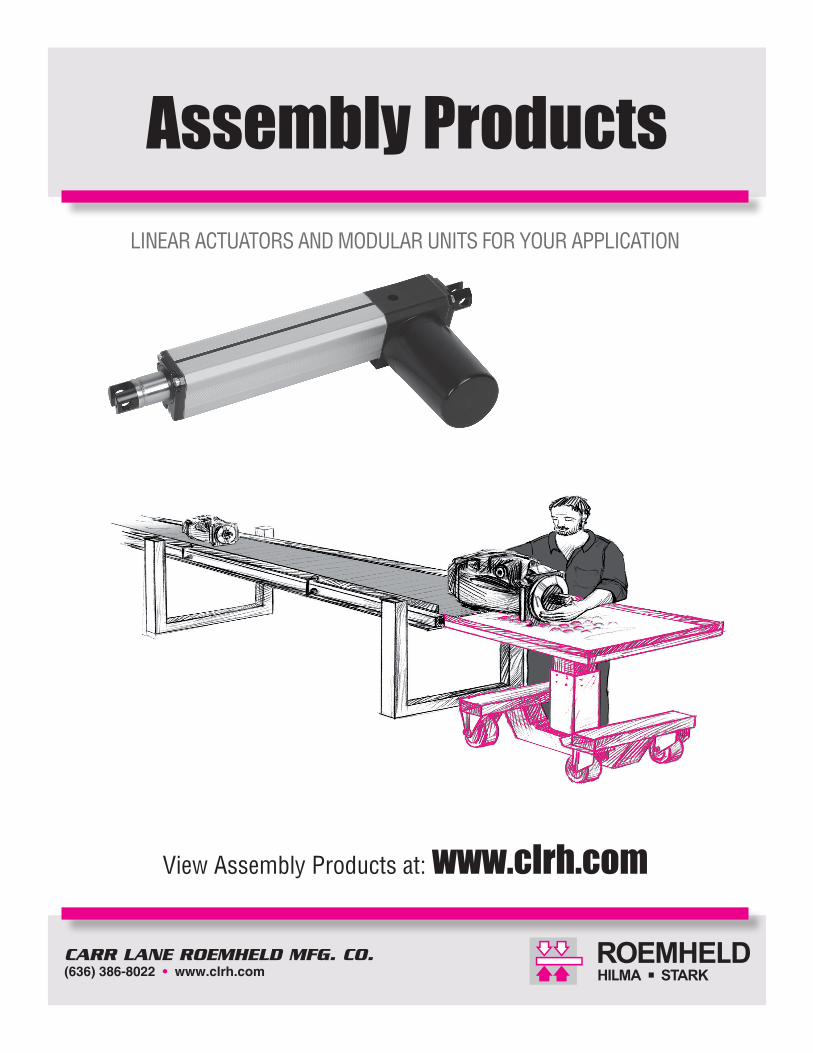
Drive, Assembly and Handling TechnologyLinear Actuators n Control, adjust and move with your choice of electric(12 VDC or 24 VDC) or hydraulic linear actuators.
Modular Units n Combine these modules in numerous ways to meet your assembly and handling needs.
RA 600Data Sheet L1.101
RA 60Data Sheet L4.201
RH 1250Data Sheet L7.101
Rotating Module Horizontal AxisRotate your workpiece about the horizontal axis via manual, hand lever, hydromechanical or electric operation. A 4 x 90˚ indexable version is availble. Maximum weight is 441 lbs. Data sheets: M1.101, M1.201.
Tilting ModuleTilt or swivel your workpiece from 0˚ to 90˚ via manual or electric operation. The design keeps the workpiece balanced while tilting. Special index angles are available upon request. Maximum weight is 220 lbs. Data sheet: M2.101.
Rotating Module Vertical AxisRotate your workpiece about the vertical axis via manual, hydromechanical or electric operation. Standard version is indexable 4 x 90˚. Special index angles availbale upon request. Maximum weight is 2,205 lbs. Data sheet: M3.101.
Lifting ModulesPrecison lifting and lowering of your workpiece. Electric and self-contained hydraulic versions. Electric versions can be synchronized. Telescoping versions available too. Maximum weight is 220 – 2,205 lbs. Maximum stroke is 7.87" – 39.4". Data sheets: M4.401, M4.202, M4.203, M4.301, M4.401, M4.501.
Cart ModulesHeavy duty carts are designed to interface and move individual modules or modular combinations, with or without their workpiece. All carts are equipped with a parking brake. Data sheet: M5.101.
Floor ModulesHeavy duty floor modules come equipped with leveling feet and you can mount one or more individual modules on the same base. Data sheets: M6.101, M6.201.

Subject to change. For further details, including detailed dimensions and mounting instructions, visit www.clrh.com.
6/13 763
CARR LANE ROEMHELD MFG. CO.Sales — Phone (314) 647-6200 Fax (314) 647-5736
Engineering — Phone 1-800-827-2526 Web www.clrh.com
Assembly and Handling Technology
Modular Units n Application and combination examplesLifting module operated by foot pedal with rotating module vertical axis
Here a complex hydraulic subassembly requires access to 5 sides during the installation of its components.The employee can rotate the workpiece 360˚ in both directions about the vertical axis of this rotating module. Now the employee can select the most ergonomic position via manual or electric operation. Model versions with indexing are available too; standard index angles are 45˚, 60˚, 90˚, 120˚.
The appropriate working height is adjusted by the foot pedal of the self-contained hydraulic lifting module.
Lifting module operated by hand pendant with rotating module horizontal axis
Multi-shift organizations know that every shift change also ushers in the change of each and every employee’s size and ability. Modular combinations adapt to such changes and this one is composed of two modules: electric lift and horizontal-axis rotating. The electric lifting module effortlessly adjusts to an employee‘s height via a hand
or foot push-button pendant. The horizontal-axis rotating module does just what its name implies; it spins a workpiece about its horizontal axis. It has 360˚ of rotation in both directions. Push or pull your workpiece to rotate the version without indexing or automatically index to your next position using the hand-lever or foot-pedal versions.
Electrically operated lifting module in sync
Assembly of truck axles is carried out by two employees at the same time. Components are installed and fastened from above as well as from both ends. The working height is adjusted via a foot pendant that controls two synchronized electric lifting modules. The synchronized lifts guarantee a level work surface throughout the entire stroke. The lifting modules are mounted to a floor module to improve stability.
Lifting module operated by hand pendant with rotating module horizontal axis
The assembly and testing of heavy workpieces such as axial piston machines is carried out at many stations. Transfer from station to station is made easy by fastening a tabletop plate to a hydraulic lift module that is mounted on top of a cart module.Applying the brake on the cart module locks the unit in place. The operator can easily raise or lower the tabletop by pumping the foot pedal of the hydraulic lifting module.
Lifting module operated by foot pedal with tilting module and rotating module vertical axis
Optimum assembly of car seats requires the ability to quickly and easily move the seat into different positions. This modular combination allows the employee to raise, lower, rotate and tilt the seat. The tilting module is equipped with a pneumatic balancer that counteracts almost all of the tilting torques. This means very little force is required of the employee to tilt heavy objects.
Lifting module operated by foot pedal with tilting module
Here the employee is carrying out the final assembly of an electric motor followed by a series of tests.The working height is adjusted by the foot pedal of the hydraulic lifting module. The tilting module mounted on top of the lifting module allows the employee to tilt the motor back and forth by 90˚. The integrated pneumatic-counterbalance feature makes tilting the motor a nearly effortless task.

• Self-contained units for lifting and height adjustment
• Single-pedal operation for sensitive, controlled lifting
• Square column resists torsional loads
• Choice of five stroke lengths, up to 23.62 inches
• To decend the lifting unit a maximum of 10% of Fz max. load is required
• The center of gravity should be within the traverse of the mounting bolts
OPERATION: Raise and lower unit using the same lever. Pump foot lever down 45 degrees to raise platform. To lower unit, lift lever 10 degrees to release pressure.
PRESSURE RELIEF: If pumping continues after reaching full height extension, pressure relieves automatically and returns fluid to the reservoir.
MOUNTING: Tapped holes in top and bottom plates allow attaching custom bases and tables.
CONSTRUCTION: Square column is made from anodized aluminum. Top and bottom mounting plates are black anodized aluminum. The operating lever is steel with bright zinc plating, with a molded plastic foot pedal.
Lifting Units Manual-Hydraulic
MAXIMUM TORQUE LOAD: In the case of eccentric loads, it is recommended to compensate these by counterweights. In off-position the indicated maximum torques may occur.
The forces and torques have to be considered by the operator. During the lifting motion only 50% of the maximum values are admitted.
764 8/14
CARR LANE ROEMHELD MFG. CO.Sales — Phone (314) 647-6200 Fax (314) 647-5736
Engineering — Phone 1-800-827-2526 Web www.clrh.com
Fz lifting capacity with centered load
Pump motions per 3.94 in. of stroke
Fully ExtendedHeight Stroke + A
B SqC Sq
DMx/y (Max. Torque Load)Mz (Max. Torque Load)
Part No.
Stroke A 7.87 16.54 11.81 20.47 15.75 24.41 19.69 28.35 23.62 32.28
3.823.357.7
74 ft. lbs.37 ft. lbs.
CLR-8910-01-X0-HStroke2=7.873=11.814=15.755=19.696=23.62
Stroke A 7.87 16.54 11.81 20.47 15.75 24.41 19.69 28.35 23.62 32.28
5.915.2411.7
369 ft. lbs.221 ft. lbs.
CLR-8915-0X-X0-HMax. Lift Force2=450 lbs.4=900 lbs.6=1350 lbs.
Stroke2=7.873=11.814=15.755=19.696=23.62
Stroke A 7.87 20.47 11.81 24.41 15.75 28.35 NA NA NA NA
5.91NA
11.35.90 ft. lbs.2.95 ft. lbs.
CLR-8919-06-X0-HStroke2=7.873=11.814=15.75
225 450 900 1350 1350 lbs lbs lbs lbs lbs
8 8 8 10 10
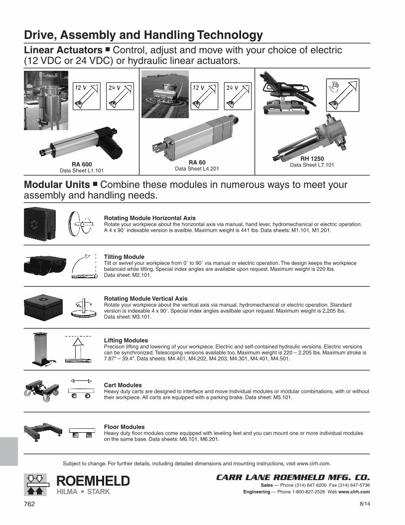
Lifting Units
Model Specifications
4 Load models available(225 lbs., 450 lbs., 900 lbs. and 1350 lbs.)Each model available in 5 different strokes.
Stroke Dim A7.87 16.5411.81 20.4715.75 24,4119.69 28.3523.62 32.28
Lifting motion is generated by an electrical motor with a spindle lifting gear. Lifting control is by push buttons with touch control contact.
Lifting motion is generated by an electrical motor with a self-locking spindle drive. Lifting control is by a hand panel or foot switch or alternatively by a primary electric control.
Contact engineering 800-827-2526 for full technical data and electrical control options.
Electrical MechanicalSingle Lifting
Electrical-Mechanical
Electro-MechanicalDouble Telescopic Lifting
Double Telescopic Lifting
Technical Specifications
Lifting Speed 2.75 in/secElectric Connection 230 V AC/50HzRating 0.75 KWControl Voltage 24 VDCDuty Cycle 20% EDMaximum Lifting (Fz) 450 lbs.Maximum Torque (Mx/y) 370 ft. lbs.Maximum Torque (Mz) 220 ft. lbs.
Single Lifting
Maximum Torque LoadTotal Mx/y 369 ft. lbs.Mz 222 ft. lbs.
Contact engineering 800-827-2526 for full technical data and electrical control options. Reference: Model No. 8915-0X-X0-X
8/14 765
CARR LANE ROEMHELD MFG. CO.Sales — Phone (314) 647-6200 Fax (314) 647-5736
Engineering — Phone 1-800-827-2526 Web www.clrh.com
Part No. Stroke ACLR-8924-02-44-E 17.32 18.50CLR-8924-02-54-E 21.26 20.47CLR-8924-02-74-E 29.13 24.41CLR-8924-02-94-E 37.01 28.35
Subject to change. For further details, including detailed dimensions and mounting instructions, visit www.clrh.com.
766 8/14
CARR LANE ROEMHELD MFG. CO.Sales — Phone (314) 647-6200 Fax (314) 647-5736
Engineering — Phone 1-800-827-2526 Web www.clrh.com
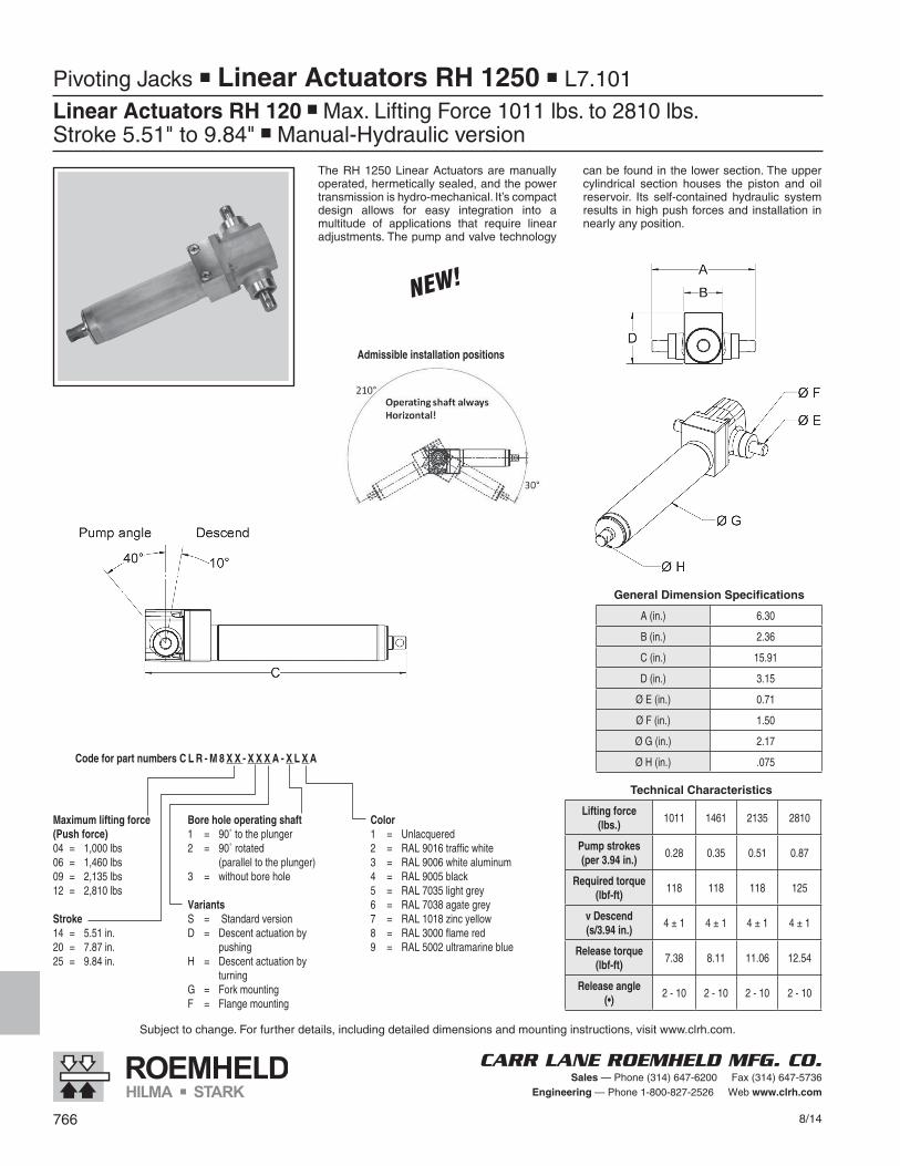
Pivoting Jacks n Linear Actuators RH 1250 n L7.101
Linear Actuators RH 120 n Max. Lifting Force 1011 lbs. to 2810 lbs.Stroke 5.51" to 9.84" n Manual-Hydraulic version
The RH 1250 Linear Actuators are manually operated, hermetically sealed, and the power transmission is hydro-mechanical. It’s compact design allows for easy integration into a multitude of applications that require linear adjustments. The pump and valve technology
can be found in the lower section. The upper cylindrical section houses the piston and oil reservoir. Its self-contained hydraulic system results in high push forces and installation in nearly any position.
General Dimension Specifications
A (in.) 6.30
B (in.) 2.36
C (in.) 15.91
D (in.) 3.15
Ø E (in.) 0.71
Ø F (in.) 1.50
Ø G (in.) 2.17
Ø H (in.) .075
Technical Characteristics
Lifting force(lbs.)
1011 1461 2135 2810
Pump strokes(per 3.94 in.)
0.28 0.35 0.51 0.87
Required torque(lbf-ft)
118 118 118 125
v Descend(s/3.94 in.)
4 ± 1 4 ± 1 4 ± 1 4 ± 1
Release torque(lbf-ft)
7.38 8.11 11.06 12.54
Release angle(•)
2 - 10 2 - 10 2 - 10 2 - 10
Code for part numbers C L R - M 8 X X - X X X A - X L X A
Maximum lifting force (Push force)04 = 1,000 lbs06 = 1,460 lbs09 = 2,135 lbs12 = 2,810 lbs
Stroke14 = 5.51 in.20 = 7.87 in.25 = 9.84 in.
Bore hole operating shaft1 = 90˚ to the plunger2 = 90˚ rotated
(parallel to the plunger)3 = without bore hole
VariantsS = Standard versionD = Descent actuation by
pushingH = Descent actuation by
turningG = Fork mountingF = Flange mounting
Color1 = Unlacquered2 = RAL 9016 traffic white3 = RAL 9006 white aluminum4 = RAL 9005 black5 = RAL 7035 light grey6 = RAL 7038 agate grey7 = RAL 1018 zinc yellow8 = RAL 3000 flame red9 = RAL 5002 ultramarine blue
Admissible installation positions

Pivoting Jacks
Installation Example:Scissors-Jack height adjustment
Installation Example:Linkage height adjustment
Application Example:Portable lifting table for fixtures. Single-lever operation allows convenient raising and lowering.
8/14 767
CARR LANE ROEMHELD MFG. CO.Sales — Phone (314) 647-6200 Fax (314) 647-5736
Engineering — Phone 1-800-827-2526 Web www.clrh.com
Installation Example:Angular adjustment of back rests or covers